
The excitation and emission of terahertz surface plasmon ... · Highly transparent materials for...
17
C. R. Physique 9 (2008) 215–231 http://france.elsevier.com/direct/COMREN/ Recent developments in terahertz optoelectronics/Développements récents en optoélectronique térahertz The excitation and emission of terahertz surface plasmon polaritons on metal wire waveguides Jason A. Deibel, Kanglin Wang, Matthew Escarra, Nicholas Berndsen, Daniel M. Mittleman ∗ Department of Electrical and Computer Engineering, Rice University, MS 366, ECE Department, PO Box 1892, Houston, TX 77251-1892, USA Available online 4 January 2008 Abstract The development of effective techniques for guiding pulsed terahertz radiation is essential for the continued development of terahertz spectroscopy and imaging applications based on the technique of time-domain spectroscopy. Terahertz surface plasmon polaritons (SPPs) can be excited and guided on cylindrical metal wires with low loss and dispersion. This propagating surface wave, known as a Sommerfeld wave, possesses radial polarization, which is not well matched with conventional sources of pulsed terahertz radiation. A photoconductive terahertz antenna with radial symmetry produces radiation that more efficiently couples to the wire waveguide. At the end of the wire, terahertz SPPs emit radiation into free-space that exhibits frequency-dependent diffraction. To cite this article: J.A. Deibel et al., C. R. Physique 9 (2008). © 2007 Académie des sciences. Published by Elsevier Masson SAS. All rights reserved. Résumé Plasmons-polaritons de surface le long d’un fil métallique dans le domaine THz : excitation et diffraction. Le dévelop- pement de la spectroscopie THz et des applications en imagerie THz basées sur des techniques temporelles requiert de pouvoir utiliser des guides d’ondes capables de véhiculer les impulsions électromagnétiques THz. Les plasmons-polaritons de surface peu- vent être excités le long de fils métalliques cylindriques et guidés avec peu de pertes et une faible dispersion. Cependant, ce type d’onde propagative de surface, appelée onde de Sommerfeld, possède une polarisation radiale contrairement à celle des sources conventionnelles de rayonnement THz qui est généralement linéaire. Pour résoudre ce problème, nous avons conçu une antenne de rayonnement THz qui génère une polarisation de symétrie radiale, permettant d’exciter efficacement les ondes de Sommerfeld. Nous étudions aussi la diffraction en fonction de la fréquence de l’onde de Sommerfeld dans l’espace libre en extrémité du fil métallique. Pour citer cet article : J.A. Deibel et al., C. R. Physique 9 (2008). © 2007 Académie des sciences. Published by Elsevier Masson SAS. All rights reserved. Keywords: Terahertz; Waveguides; Surface plasmon polaritons; Photoconductive antennas; Finite element method simulations Mots-clés : Térahertz ; Guide d’ondes ; Plasmons-polaritons de surface ; Antenne de rayonnement THz ; Simulation par méthode des éléments finis * Corresponding author. E-mail address: [email protected] (D.M. Mittleman). 1631-0705/$ – see front matter © 2007 Académie des sciences. Published by Elsevier Masson SAS. All rights reserved. doi:10.1016/j.crhy.2007.07.011
Transcript of The excitation and emission of terahertz surface plasmon ... · Highly transparent materials for...

C. R. Physique 9 (2008) 215–231
http://france.elsevier.com/direct/COMREN/
Recent developments in terahertz optoelectronics/Développements récents en optoélectroniquetérahertz
The excitation and emission of terahertz surface plasmon polaritonson metal wire waveguides
Jason A. Deibel, Kanglin Wang, Matthew Escarra,Nicholas Berndsen, Daniel M. Mittleman ∗
Department of Electrical and Computer Engineering, Rice University, MS 366, ECE Department,PO Box 1892, Houston, TX 77251-1892, USA
Available online 4 January 2008
Abstract
The development of effective techniques for guiding pulsed terahertz radiation is essential for the continued development ofterahertz spectroscopy and imaging applications based on the technique of time-domain spectroscopy. Terahertz surface plasmonpolaritons (SPPs) can be excited and guided on cylindrical metal wires with low loss and dispersion. This propagating surfacewave, known as a Sommerfeld wave, possesses radial polarization, which is not well matched with conventional sources of pulsedterahertz radiation. A photoconductive terahertz antenna with radial symmetry produces radiation that more efficiently couplesto the wire waveguide. At the end of the wire, terahertz SPPs emit radiation into free-space that exhibits frequency-dependentdiffraction. To cite this article: J.A. Deibel et al., C. R. Physique 9 (2008).© 2007 Académie des sciences. Published by Elsevier Masson SAS. All rights reserved.
Résumé
Plasmons-polaritons de surface le long d’un fil métallique dans le domaine THz : excitation et diffraction. Le dévelop-pement de la spectroscopie THz et des applications en imagerie THz basées sur des techniques temporelles requiert de pouvoirutiliser des guides d’ondes capables de véhiculer les impulsions électromagnétiques THz. Les plasmons-polaritons de surface peu-vent être excités le long de fils métalliques cylindriques et guidés avec peu de pertes et une faible dispersion. Cependant, ce typed’onde propagative de surface, appelée onde de Sommerfeld, possède une polarisation radiale contrairement à celle des sourcesconventionnelles de rayonnement THz qui est généralement linéaire. Pour résoudre ce problème, nous avons conçu une antennede rayonnement THz qui génère une polarisation de symétrie radiale, permettant d’exciter efficacement les ondes de Sommerfeld.Nous étudions aussi la diffraction en fonction de la fréquence de l’onde de Sommerfeld dans l’espace libre en extrémité du filmétallique. Pour citer cet article : J.A. Deibel et al., C. R. Physique 9 (2008).© 2007 Académie des sciences. Published by Elsevier Masson SAS. All rights reserved.
Keywords: Terahertz; Waveguides; Surface plasmon polaritons; Photoconductive antennas; Finite element method simulations
Mots-clés : Térahertz ; Guide d’ondes ; Plasmons-polaritons de surface ; Antenne de rayonnement THz ; Simulation par méthode des éléments finis
* Corresponding author.E-mail address: [email protected] (D.M. Mittleman).
1631-0705/$ – see front matter © 2007 Académie des sciences. Published by Elsevier Masson SAS. All rights reserved.doi:10.1016/j.crhy.2007.07.011

216 J.A. Deibel et al. / C. R. Physique 9 (2008) 215–231
1. Introduction
The last two decades of the twentieth century saw multiple exciting developments in the science and technologyassociated with the segment of the electromagnetic spectrum known as the terahertz gap (100 GHz – 30 THz). In thistime span, many developments in the fields of pulsed terahertz generation, detection, spectroscopy, and imaging werereported in scientific literature [1]. The increased availability of ultrafast lasers having pulse widths on the order of100 femtoseconds helped broaden the use of techniques for generation of pulsed terahertz radiation via semiconductorphotoconductive antennas [2,3] and optical rectification in nonlinear optical materials [4,5]. Detection of terahertzpulses was also accomplished using ultrafast lasers in conjunction with photoconductive antenna receivers [3] orelectro-optic crystals via electro-optic sampling [6]. As methods for the generation and detection of THz pulsesbecame more efficient, terahertz time-domain spectroscopy and imaging systems were shown to be effective for thecharacterization of semiconductors [7,8], imaging of biomedical systems [9,10], and trace gas detection [11]. THzspectroscopy and imaging systems have also found potential use outside of the conventional laboratory environmentfor security applications [12–15] and quality control in manufacturing [16,17]. There has also been considerableeffort directed towards terahertz spectroscopic and imaging measurements in the near-field [18–24]. Techniques suchas apertureless terahertz near-field microscopy provide a means of obtaining THz measurements with very high spatialresolution, much better than can be obtained using conventional diffraction-limited optics.
Standard terahertz time-domain spectroscopy and imaging systems used in laboratory and commercial settingstypically employ free-space optical components. These can include lenses and mirrors for the guiding, focusing,and collimating of not only the terahertz radiation, but also the near-infrared (NIR) laser radiation used to gen-erate and detect the THz pulses. These bulky free-space optics complicate the broader use of terahertz systemson several fronts. Bulk optics require space, thus increasing the overall footprint of the THz system. As a result,a typical THz spectroscopy and imaging system occupies a large amount of space. Recent advancements in lasertechnology, specifically the development of fiber-based ultrafast lasers, has lessened the ‘footprint’ of terahertz sys-tems, but a truly portable system is still challenging to construct. Second, the alignment requirements for free-spaceoptics complicates the day-to-day operation of a terahertz system, requiring highly specialized user training. Fi-nally, any optical system that relies on the use of free-space optics requires that any sample or ‘area of interest’must have direct-line-sight access available. This limits the range of possible applications. The development of ef-fective guided wave techniques and components will address many of these issues. The impact would be akin tothe impact fiber-optics had in the field of optics. In 2000, Picometrix reported the development of the first fiber-coupled terahertz transducers, which eliminated the need for free-space optical components for the NIR femtosecondlaser beam [25]. This has already revolutionized the operation of time-domain spectrometers, enabling many newexperiments that would otherwise have been nearly impossible. These fiber-coupled systems are still in very lim-ited use, and the majority of THz-TDS systems still rely on free-space optics. Even so, the dramatic impact ofthis advance is already a compelling demonstration of the need for a waveguide approach to terahertz technolo-gies.
The chief requirements for a THz waveguide device are that it must exhibit both low loss and low dispersion. Thesetwo requirements eliminate many possible approaches that function well in other portions of the frequency spectrum.Materials that are often used for fiber optics, such as glasses and polymers, exhibit unacceptable absorption lossesat terahertz frequencies [26]. Highly transparent materials for terahertz radiation, such as high-resistivity silicon,are brittle and expensive, and therefore impractical. Another alternative, often employed for waveguiding at RF andmicrowave frequencies, is to guide the radiation through air in a confined geometry such as a metal tube. This can workwell for the case of continuous-wave (CW) terahertz beams, for which only loss, and not dispersion, is a concern [27].However, due to the presence of a cutoff frequency, a hollow waveguide will significantly disperse any broadbandterahertz pulse propagating through it [28,29]. Other groups have reported the use of polymeric photonic crystal fibersas waveguides for THz pulses [30–32]. While the loss and dispersion for this guiding technique can be improved incomparison to that for hollow metal waveguides, the group velocity dispersion is still significant.
One exception which has been studied thoroughly is the metal parallel plate geometry, which can provide both lowloss and low dispersion for terahertz pulses [33,34]. In this case, the loss results from the finite conductivity of themetal plates, as well as from surface roughness. This approach is compatible with THz waveguide spectroscopy, ashas been demonstrated in a variety of spectroscopic measurements of samples including nanometer-thick layers of

J.A. Deibel et al. / C. R. Physique 9 (2008) 215–231 217
water [35], polycrystalline thin films [36], silicon [37], and photonic crystals [38]. The use of low index discontinuityand metallic slit terahertz waveguides has also been reported recently and show promise in terms of loss and dispersionparameters [39,40].
In recent years, we have studied a guiding technique unlike the ones mentioned above. This technique is based onthe propagation of a surface wave on the exterior surface of a metal cylinder. In fact, several groups have now shownthat a simple metal wire can be employed as a terahertz waveguide, exhibiting very low loss and negligible dispersion[41–44]. This weakly guided surface wave phenomenon can be described in a variety of ways. It is similar to thetransverse electromagnetic (TEM) mode of a coaxial waveguide [45]. The primary mode of the wire waveguide is acylindrically symmetric surface guided wave that was first described by Sommerfeld in 1899, and is now known as aSommerfeld wave [46,47]. This surface excitation is also equivalent to a surface plasmon polaritons (SPP) propagatingalong the wire surface [48,49]. The SPP arises from the collective oscillations of the conduction electrons at thedielectric interface on the metal surface, in response to the driving electromagnetic surface wave.
As the metal wire possesses a circular cross-section and the electric field of the guided mode points away from thesurface of the wire, we describe the primary mode of the waveguide as having a radial polarization. The cylindricalsurface of the wire provides a very a small exposed area for the electromagnetic field to interact with, minimizingattenuation due to the finite conductivity of the metal. We have reported that the spectrum-weighted amplitude attenu-ation coefficient for THz wire waveguide (0.9 mm diameter) is α = 0.03 cm−1, the lowest loss for any broadband THzwaveguide ever reported [41]. While the first experiments with terahertz metal wire waveguides reported relatively lit-tle evidence of dispersion, subsequent efforts have shown that dispersion is measurable under certain conditions [48].It has also been reported that the presence of thin, non-dispersive, dielectric coating along the surface of a metal wiresignificantly distorts terahertz pulse propagation [50]. The low loss and dispersion of the terahertz wire waveguidecoupled with its structural simplicity permitted the first-ever demonstration of a pulsed terahertz endoscope [41].Metal wire waveguides can also be used for waveguide-based spectroscopic measurements [51].
Two aspects of the terahertz metal wire waveguide require additional attention, in order for it to be useful as atool for spectroscopy and imaging applications. The first involves the method of exciting the THz surface plasmonpolaritons on the waveguide. Second, it is necessary to understand what happens at the end of the wire waveguide,since spectroscopic studies will typically require measurements of the pulse after it propagates off the end of the wire.The emission of the THz SPPs at the end of the wire must therefore be fully understood. In this paper, we discuss ourearly experiments with THz wire waveguides, including the scattering mechanism that was used for excitation of thepropagating SPP. Using Finite Element Method (FEM) simulations, we study this coupling process and quantify thecoupling efficiency. Next, we develop a photoconductive antenna with radial symmetry and show with both modelingand experimental results that use of this novel antenna structure can significantly increase the amount of THz radiationthat can be coupled to a wire waveguide. Finally, we study the frequency-dependent emission of surface plasmonpolaritons propagating off the end of the wire waveguide.
2. Coupling linearly polarized THz radiation to a metal wire waveguide
In our first set of experiments, the radial mode of the metal wire waveguide is excited via a scattering mechanism.Horizontally polarized terahertz pulses are focused onto the 0.9 mm diameter stainless steel wire waveguide (Fig. 1).An identical stainless steel wire is placed perpendicular to the waveguide near the focal spot of the beam. A smallportion of the radiation scattered from this crossed wire structure excites the radially polarized surface wave that prop-agates along the metal wire [41,44]. This radially polarized guided wave is known as a Sommerfeld wave [42,47] andcan also be described as an azimuthally polarized surface plasmon [49]. The experimental results from the couplingconfiguration described above indicate that less than 1% of the power of the incident terahertz beam is coupled tothe wire waveguide by this scattering process. Due to the difficulty of measuring the entire scattered field, it has notbeen possible to obtain a more accurate estimate of the coupling efficiency. Here, we develop a numerical model ofthe dual-wire THz coupler, using the finite element method (FEM), in order to demonstrate the nature of the couplingand to provide a method to more accurately quantify the coupling efficiency.
The wire waveguide is modeled in three dimensions using a commercially available FEM package. Its outer bound-ary is defined as a perfect electrical conductor (PEC). It should be noted that a more exact model could consider thesurface impedance of the wire’s outer boundary and the Drude conductivity of the metal. This would be necessary inorder to correctly model the ohmic loss of the wire waveguide [44]. However, it is our intention to model only the

218 J.A. Deibel et al. / C. R. Physique 9 (2008) 215–231
Fig. 1. Excitation of THz surface wave on a metal wire using a scattering configuration.
coupling efficiency of the experiment and not to consider the waveguide’s inherent loss. A second wire, the couplerwire, is placed in the vicinity of the wire waveguide, but in a direction perpendicular to it. The coupler wire has thesame diameter as the waveguide and is also modeled as a PEC. The distance between the closest outer surfaces of thetwo wires is 0.5 mm. The linearly polarized terahertz pulse is modeled as a plane wave whose k-vector is incident ata 45 degree angle from the axis of the wire waveguide. The plane wave, 2 cm in diameter, is directed such that itscenter is incident at the center of the gap between the waveguide and coupler wires. The size of the plane wave ischosen to mirror the size of the loosely focused terahertz beam used in the actual scattering experiment. The linearinput polarization is chosen such that its direction lies in the same plane (x–z plane) occupied by the long axis ofthe wire waveguide, again mirroring the experiment. The simulation domain is bounded by a box of air confining thewaveguide and coupler wires and the input plane wave. A low-reflecting boundary condition is selected for the outerwalls of the domain. This condition is chosen such that any back-reflections of the EM waves in the simulation areminimized.
Prior to solving, the 3-D simulation domain is discretized into approximately 1.8 million tetrahedral mesh elementsyielding a computational model consisting of 2.1 million degrees of freedom. The large number of mesh elements isdue to the need for at least 3, but generally more, mesh elements per wavelength of the propagating radiation [52].The experiment is simulated using a time-harmonic solver, so only one input frequency is considered at a time. Themodel problem is solved using an iterative Generalized Minimal Residual (GMRES) iterative solver with SymmetricSuccessive Overrelaxation (SSOR) matrix preconditioning [53,54]. For a waveguide 15 cm long, a workstation withdual 64-bit processors and 14 GB of RAM arrives at a solution in less than 20 hours.
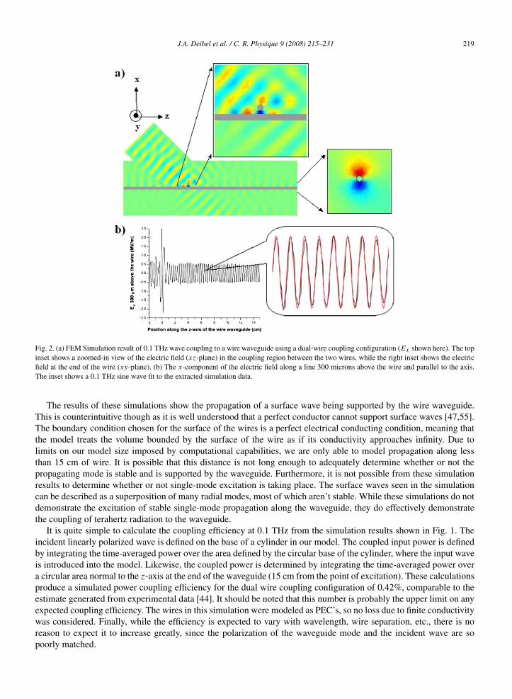
Simulation results for a frequency of 0.1 THz are shown in Fig. 2. The incident plane wave can be seen scatteringat the gap between the wire coupler and waveguide. Evidently the majority of the plane wave propagates unimpededand only a small amount of the incident radiation is coupled to the radial mode of the waveguide. A plot of thex-component of the guided wave’s electric field at the end of the wire is also shown highlighting the radial nature ofthe propagating mode. At the same location, the y-component of the field is similar to the aforementioned plot, butrotated by 90 degrees. Fig. 2(b) is a plot of the x-component of the electric field 300 microns above the wire and alongits z-axis. The large peak at z = 0 is part of the incident input wave. It can be seen that both forward and backwardpropagating modes are excited. Recalling that the wires are modeled as PEC’s, we expect little attenuation once themode is excited, which is consistent with the results of the calculation. A sine wave with a frequency of 0.1 THzcan be easily fit to the oscillating electric field along the waveguide, demonstrating that the model is simulating wavepropagation. Any noise or amplitude fluctuation present in the plot in Fig. 2(b) is due to an insufficient mesh densitywhich is limited by the computational capabilities of the simulation computer.
J.A. Deibel et al. / C. R. Physique 9 (2008) 215–231 219
Fig. 2. (a) FEM Simulation result of 0.1 THz wave coupling to a wire waveguide using a dual-wire coupling configuration (Ex shown here). The topinset shows a zoomed-in view of the electric field (xz-plane) in the coupling region between the two wires, while the right inset shows the electricfield at the end of the wire (xy-plane). (b) The x-component of the electric field along a line 300 microns above the wire and parallel to the axis.The inset shows a 0.1 THz sine wave fit to the extracted simulation data.
The results of these simulations show the propagation of a surface wave being supported by the wire waveguide.This is counterintuitive though as it is well understood that a perfect conductor cannot support surface waves [47,55].The boundary condition chosen for the surface of the wires is a perfect electrical conducting condition, meaning thatthe model treats the volume bounded by the surface of the wire as if its conductivity approaches infinity. Due tolimits on our model size imposed by computational capabilities, we are only able to model propagation along lessthan 15 cm of wire. It is possible that this distance is not long enough to adequately determine whether or not thepropagating mode is stable and is supported by the waveguide. Furthermore, it is not possible from these simulationresults to determine whether or not single-mode excitation is taking place. The surface waves seen in the simulationcan be described as a superposition of many radial modes, most of which aren’t stable. While these simulations do notdemonstrate the excitation of stable single-mode propagation along the waveguide, they do effectively demonstratethe coupling of terahertz radiation to the waveguide.
It is quite simple to calculate the coupling efficiency at 0.1 THz from the simulation results shown in Fig. 1. Theincident linearly polarized wave is defined on the base of a cylinder in our model. The coupled input power is definedby integrating the time-averaged power over the area defined by the circular base of the cylinder, where the input waveis introduced into the model. Likewise, the coupled power is determined by integrating the time-averaged power overa circular area normal to the z-axis at the end of the waveguide (15 cm from the point of excitation). These calculationsproduce a simulated power coupling efficiency for the dual wire coupling configuration of 0.42%, comparable to theestimate generated from experimental data [44]. It should be noted that this number is probably the upper limit on anyexpected coupling efficiency. The wires in this simulation were modeled as PEC’s, so no loss due to finite conductivitywas considered. Finally, while the efficiency is expected to vary with wavelength, wire separation, etc., there is noreason to expect it to increase greatly, since the polarization of the waveguide mode and the incident wave are sopoorly matched.
220 J.A. Deibel et al. / C. R. Physique 9 (2008) 215–231
3. A photoconductive antenna with radial symmetry
The very low coupling efficiency associated with the aforementioned dual-wire coupling scheme results mainlyfrom the polarization mismatch between the terahertz source and the primary mode of the wire waveguide. Whetherthe method of terahertz pulse generation is via a photoconductive antenna or optical rectification in a NLO crystal,the generated pulse is linearly polarized [56]. A notable exception to this is recent work performed by Chang et al.demonstrating the production of a radially polarized terahertz beam via an optical rectification process [57]. Whileothers have sought to address the coupling problem via modification of the waveguide itself, our efforts have focusedon the source of the terahertz radiation [58]. We have shown that a novel photoconductive terahertz antenna with radialsymmetry can adequately addresses the coupling efficiency issue [42,59,60].
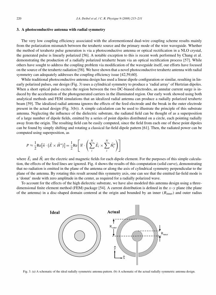
While traditional photoconductive antenna design has used a linear dipole configuration or similar, resulting in lin-early polarized pulses, our design (Fig. 3) uses a cylindrical symmetry to produce a ‘radial array’ of Hertzian dipoles.When a short optical pulse excites the region between the two DC-biased electrodes, an annular current surge is in-duced by the acceleration of the photogenerated carriers in the illuminated region. Our early work showed using bothanalytical methods and FEM simulations that an idealized radial antenna can produce a radially polarized terahertzbeam [59]. The idealized radial antenna ignores the effects of the feed electrode and the break in the outer electrodepresent in the actual design (Fig. 3(b)). A simple calculation can be used to illustrate the principle of this substrateantenna. Neglecting the influence of the dielectric substrate, the radiated field can be thought of as a superpositionof a large number of dipole fields, emitted by a series of point dipoles distributed on a circle, each pointing radiallyaway from the origin. The resulting field can be easily computed, since the field from each one of these point dipolescan be found by simply shifting and rotating a classical far-field dipole pattern [61]. Then, the radiated power can becomputed using superposition, as
P ≈ 1
2Re
[�n · ( �E × �H ∗)] = 1
2Re
[−→n ·
(N∑i
�Ei ×N∑i
�H ∗i
)]
where �Ei and �Hi are the electric and magnetic fields for each dipole element. For the purposes of this simple calcula-tion, the effects of the feed lines are ignored. Fig. 4 shows the results of this computation (solid curve), demonstratingthat no radiation is emitted in the plane of the antenna or along the axis of cylindrical symmetry perpendicular to theplane of the antenna. By rotating this result around this symmetry axis, one can see that the emitted far-field mode isa ‘donut’ mode with zero amplitude in the center, as required for a radially polarized wave.
To account for the effects of the high dielectric substrate, we have also modeled this antenna design using a three-dimensional finite element method (FEM) package [54]. A current distribution is defined in the x–y plane (the planeof the antenna) in a disc-shaped domain centered at the origin and bounded by an inner (Rinner) and outer radius
Fig. 3. (a) A schematic of the ideal radially symmetric antenna pattern. (b) A schematic of the actual radially symmetric antenna design.

J.A. Deibel et al. / C. R. Physique 9 (2008) 215–231 221
Fig. 4. The calculated far-field radiation pattern in the y–z plane, neglecting substrate effects. The solid horizontal line indicates the z-axis, whichis the rotational symmetry axis of the antenna. The open circles show the results of the FEM simulations.
(Router). To approximate the annular current pattern of the antenna, the area encompassed by this disc is assigned thefollowing time-varying current,
�J =[(
x
rαe−βr
)x +
(y
rαe−βr
)y
]ε0jωejωt
where α and β are constants chosen such that the magnitude of J decays to zero at the outer edge of the disc. Thiscurrent distribution is surrounded by a spherical surface in the far field of the antenna, on which the emitted field iscomputed. Low reflecting boundary conditions are used to eliminate finite size effects in the computation. Typicallya mesh of approximately 60 000 elements is used to compute the radiated field pattern. We have modeled both theantenna in empty space, and also the more realistic situation of an antenna situated on a dielectric half space. Forthis latter case, we have used a dielectric of ε = 12.25, the approximate value for GaAs. A stationary linear iterativesolver was used to determine the electromagnetic fields emitted by the antenna at a variety of frequencies for both thefree-space and half-space scenarios. The results from the FEM simulations are in good agreement with the intuitivepicture described above (see open circles in Fig. 4). Good agreement is observed in both the angle and width of theemitted lobe. Fig. 5(a) is a three-dimensional plot of the FEM simulation further demonstrating the radial polarizationof the beam emitted by the simulated ideal antenna. In the case of an antenna on a dielectric half-space, the lobedpattern is largely preserved, except that most of the energy is radiated into the substrate (greater than 98%) (Fig. 5(b)).This is similar to the effect observed for dipole substrate antennas [62].
The radially symmetric photoconductive antenna was simulated with the same three-dimensional electromagneticwave FEM package used to model the dual-wire THz waveguide coupler. The center of the antenna consists of acircular electrode 5 µm in diameter, fed by an electrode 1 µm wide that approaches the center from the negative y-axisdirection. The separation between the center electrode and the 10 µm wide outer electrode is 100 µm. At the bottomof the antenna where the outer ring electrode approaches the feed electrode, there is a 7.5 µm gap on each side of thefeed electrode. To simplify the model, the boundaries of the electrodes are defined as PEC’s. In order to model anactual experimental configuration, the antenna is placed at the interface between a section of air and a 0.5 mm thickdielectric substrate, with a dielectric constant of 13. As is the case for standard THz-TDS [63], a substrate-matchedhyperhemispherical silicon dome (2 mm radius) is placed on the other side of the substrate in order to couple thebeam into free space and collimate it. For comparison, an idealized radial antenna (with no feed electrode and no gapin the outer circular electrode) with a 100 µm radius is also placed on the same substrate with the same silicon domeconfiguration.
For the modeling of the antenna configuration, we use a two step approach, in which we model first the DC fieldspresent in the antenna and use those results to simulate the generation of terahertz radiation [54]. In the first step,

222 J.A. Deibel et al. / C. R. Physique 9 (2008) 215–231
Fig. 5. (a) FEM simulation of the power emitted by an “ideal” radial antenna in free space at 0.5 THz. The antenna is located at the center of thesphere within the xy-plane. The z-axis passes through the dark blue point at the center of the radial mode as projected onto the sphere. (b) A polarplot of the radiation pattern for the radial antenna on a dielectric half-space, computed using a FEM simulation. The vast majority of the power isradiated into the high dielectric substrate.
Fig. 6. FEM simulation results of the radial antenna in a typical THz configuration. (a) & (b) Plots of the x- and y-component of the electric fieldfor the idealized radial antenna. (c) & (d) Plots of the x- and y-component of the electric field for the actual radial antenna.
the outer electrode is grounded and a potential is applied to the center electrode. A charge density with a Gaussiandistribution and a 1/e width of 40 µm is placed at the center of the antenna. This mimics the charge carriers generatedin the substrate by the optical pump pulse in a typical photoconductive generation scheme. The electrostatic fields arecomputed using the FEM solvers and then those fields are used as the time-varying input fields for the electromagneticwave propagation model. In all, these models typically consisted of approximately 90 000 mesh elements and wererun in less than 4 hours on Pentium PC with 2 GB of RAM.
The results of the radial antenna simulations are presented in Fig. 6. All four plots show the generated radiationfields at 0.1 THz in the x–y plane immediately after the silicon dome, which is visible in addition to the substrate.Figs. 6(a) and (b) show the horizontal and vertical components of the generated electric field from the idealized radialantenna. The generated field from the idealized antenna is perfectly radial. The polarization of the generated field fromthe actual radial antenna structure (Figs. 6(c) and (d)) is not perfectly radially oriented. The lack of radial symmetryin the field generated by the actual antenna is caused by the lack of symmetry in the actual antenna design. Both thebreak in the outer electrode and the presence of the feed electrode create asymmetry in the lower half of the antennastructure. This results in the y-component of the electric field being stronger in amplitude than the x-component andthe strongest parts of the x-component of the generated field not being centered on the antenna. While it is clear from

J.A. Deibel et al. / C. R. Physique 9 (2008) 215–231 223
Fig. 6 that the actual radial antenna design does not generate a perfectly radial terahertz beam, the results indicate thatthe beam is in fact largely radially polarized. By calculating the spatial overlap of the fields between these two cases(idealized antenna vs. actual antenna), we find that approximately 60% of the power generated by the actual antennaemerges in the form of a radial mode.
In order to test the effectiveness of the new antenna design, we further employ FEM simulation tools to modelthe coupling of the radial antenna output to a wire waveguide. The same models used in the previous section aremodified to include the addition of a wire waveguide directly end-coupled to the center and exterior of the silicondomes. The wire waveguide’s dimensions, 0.9 mm diameter, are identical to the waveguides used in the simulationsreported earlier in this work and in previously published experimental results [41,44]. For simulations involvingthe idealized antenna, the wire waveguide is 2.75 cm long; whereas those with the actual radial antenna design thewaveguide is 1.75 cm long. This discrepancy is a result of our computer capability, which constrains the simulationsto a maximum number of mesh elements. As the geometry with the actual radial antenna is much more complex, theantenna structure requires more mesh elements than the idealized antenna. Consequently, with a reduced number ofmesh elements available, the wire waveguide is shortened in order for the simulation to be successful. As with thesimulation results presented previously, the wire waveguide is modeled as a PEC.
FEM simulations at 0.1 THz of the idealized and actual radial antennas coupled to wire waveguides can be seenin Fig. 7. Plots of the field at the end of the wire from the idealized antenna results show that the idealized antennais capable of exciting the low-order radial mode of the wire waveguide. Likewise, while less power is coupled to the
Fig. 7. FEM simulation model of radial antenna coupling to a wire waveguide. (a) Plot of Ex at the end of a waveguide coupled to an ideal radialantenna. (b) Plot of Ey at the end of a waveguide coupled to an ideal radial antenna. (c) Plot of Ex at the end of a waveguide coupled to an actualradial antenna. (d) Plot of Ey at the end of a waveguide coupled to an actual radial antenna.

224 J.A. Deibel et al. / C. R. Physique 9 (2008) 215–231
waveguide, the actual antenna design is also shown to be capable of exciting the radial mode. A more quantitativeobservation can be obtained by performing a coupling efficiency calculation similar to the one performed previously.The power available to be coupled into the waveguide is calculated by integrating the time-averaged power over aboundary in the x–y plane immediately after the silicon dome. The time-averaged power is integrated over a boundaryat the end of the waveguide and normal to it. The areas integrated over in both cases are identical. For the actual radialantenna design, this calculation yields a coupling efficiency of approximately 56%, an improvement of more than2 orders of magnitude over the 0.4% coupling efficiency obtained via the scattering mechanism discussed earlier.Simulations with the waveguide removed were also performed. For both the case of the idealized and actual antennastructures, only a very tiny amount of power propagated to the end of the simulation domain.
It should be noted here that our definition of efficiency is not the same as the overall efficiency of the system. Ifone were to consider the efficiency of the ultrafast laser system and the overall photoconductive generation of theterahertz in addition to the coupling efficiency, the reported numbers would be reduced, due to the low efficiency ofthe photoconductive generation process. An important note though is that our scheme fully exploits the majority of thepower generated by the radial photoconductive antenna. It is well known that for a linear dipole antenna located at anair-dielectric interface, most of the power generated by the dipole is transmitted into the dielectric [62]. Our previousresults predict that for a radial antenna at an air-dielectric interface, over 98% percent of the power is radiated into thedielectric [59]. The conventional substrate + matched silicon dome configuration permits most of the power availableto be coupled to the waveguide. Others have reported experimental results using a radial antenna similar in design toours, but in a configuration involving optically pumping the antenna through the dielectric substrate [42]. In this case,there is a significant drawback in that the amount of power available to be coupled to the waveguide is significantlylower because most of the terahertz radiation is lost into the high dielectric substrate. Another method for excitingthe radial mode of a wire at terahertz frequencies involves coupling via a series of periodically spaced grooves milledinto the waveguide [58]. This method is quite versatile, in that it permits the facile manipulation of the terahertz pulseshape, although no estimates of coupling efficiency have been advanced.
Following the FEM simulation efforts, photoconductive antennas with radial symmetry were fabricated and tested.The antennas were photolithographically defined on a 500 µm thick semi-insulating GaAs substrate. Subsequentto device fabrication, a matched hyperhemispherical silicon dome was mounted on the opposite side of the GaAssubstrate. The results reported here used antennas consisting of an 8 µm diameter inner electrode separated from theouter electrode by 75 µm. A 20 V DC bias was applied to the antenna with the center circular electrode serving asthe anode. The antenna was pumped with a free space 800 nm, 100 fs laser pulse with an average power of 25 mW.The pump beam was focused on the center of the anode such that only a portion of the region between the electrodeswas illuminated. A 0.9 mm diameter, 27 cm long, stainless steel wire waveguide was end-coupled to the emitter byplacing it in contact with the silicon dome at its apex. The terahertz pulse was detected at the end of the wire witha fiber-coupled photoconductive receiver. The receiver used here was a standard bowtie antenna, sensitive to onlyone linear polarization component. The described setup is depicted in Fig. 8. The experimental configuration of theend-coupling of the waveguide to the antenna assembly mirrored the configuration simulated in the previous section.
The primary advantage of the fiber-coupled terahertz receiver is that it permits detection at various positions closeto the end of the wire waveguide. As reported in our previous work, there is only a very small amount of THz radiationpresent on the center axis at the end of the wire waveguide [44]. The strongest part of the guided THz field is typicallylocated at a vertical or horizontal offset of a few mm from the center axis. Fig. 9 shows plots of the experimentalresults from the testing of the coupling capability of the radial antenna. The data shown here are measurements of thehorizontal component of the radially polarized propagating mode. It can be seen in Fig. 9(a), that only a very smallsignal is detected when the detector is placed at the center axis at the end of the wire. At a horizontal offset of +3 mmfrom the axis, a strong terahertz signal is present. A strong signal is present as well when the receiver antenna isplaced at a horizontal offset of −3 mm. While these signals are virtually equal in magnitude, there is a clear polarityreversal between the two measurement positions. The equivalent magnitude of both signals and the reversal of polaritybetween them demonstrate the radial polarization of the guided mode, consistent with simulation results.
The increased coupling capability offered by the use of the radial antenna and the utility of the waveguide is furtherdemonstrated in Fig. 9(b). When the wire waveguide is removed and measurements are made with the receiver at thesame offset positions described above, the generated terahertz pulse is considerably smaller at a distance of 27 cm.In addition, the polarity reversal is absent, as would be expected for a diverging spherical wave. A similar effect wasalso seen in the simulations reported in the previous section when the waveguide was removed. In fact, any standard

J.A. Deibel et al. / C. R. Physique 9 (2008) 215–231 225
Fig. 8. Setup for experimental testing of the radially symmetric terahertz emitter antenna. The emitter was pumped with a free-space beam.A 0.9 mm diameter, 27 cm long wire waveguide was end-coupled to the silicon dome of the emitter. THz radiation was detected at the end of thewaveguide by a fiber-coupled LT-GaAs detector sensitive to only the horizontal polarization component.
Fig. 9. Time-domain measurements of the terahertz pulse detected 27 cm away from the radial emitter. Measurements include the wire waveguidebeing present (a) and absent (b). The terahertz pulse exhibits a polarity reversal when measured at opposite locations at the end of the waveguide,a hallmark of the guided mode’s radial polarization.
terahertz spectroscopy or imaging setup in which the beam propagates through a distance this large would normallyemploy several lens or mirrors to confine and guide the beam. The alignment of such beam-guiding optics can bedifficult and often results in signal attenuation and bandwidth reduction. These results illustrate the value of the radialantenna-waveguide configuration.
A qualitative determination of the coupling efficiency of the radial antenna-wire waveguide configuration can beobtained by comparing the two sets of results shown in Fig. 9. At the +3 mm horizontal offset, the peak-to-peakamplitude of the terahertz signal measured at the end of the waveguide is approximately 20 times larger than that forthe pulse measured at the same position when the waveguide is not present. While that number does not representthe actual power coupling efficiency since these waveforms were measured at only a single point in space, it providessome insight into the considerable advantages of using the radial antenna-wire waveguide configuration.
4. Terahertz SPP emission from wire waveguides
In most reports of terahertz wire waveguides, the THz surface waves are measured by allowing them to propa-gate towards the end of the wire followed by detection using either photoconductive dipole antennas, or electro-opticsampling [41–44,51,58,60,64]. Walther et al. studied the far-field angular emission patterns from long metal tips andshowed that they function like THz traveling wave antennas [64]. Little attention has been paid to the near-field and

226 J.A. Deibel et al. / C. R. Physique 9 (2008) 215–231
intermediate-field spectral and spatial properties of the wave emitted at the end of the wire. To our knowledge, an-alytical expressions describing the near-field of the end of a cylindrical wire do not exist, since the finite thicknessof the wire, which is on the order of the wavelength, must be taken into account. This lack of both experimental andtheoretical information is unfortunate, as the transition from the near-field to the far-field is quite relevant to manyrecent measurements. We also note that the propagation of cylindrically symmetric surface plasmons on metallicnanowires, and in particular their behavior near the ends of these nanostructures, has been a subject of much recentinterest in the nanophotonics literature [65,66]. The details of the coupling of these surface modes to propagatingmodes, as characterized by the near-field to far-field transition, must be understood before a meaningful interpreta-tion of the experimental results can be made. We present measurements and numerical calculations on the spatialdependence of the near- and intermediate field spectra emitted by THz surface waves near the end of cylindricalwires [67].
To perform these measurements, the THz pulses are generated and detected using a fiber-coupled photo-conductiveemitter and detector (Fig. 10). Only the component of the electric field in a plane perpendicular to the length of thewire is measured. The spatial resolution of the setup is limited to a value of approximately 6 mm, corresponding tothe aperture of the substrate lens. The advantage of the lens is that it collects and concentrates the field over a largerarea, giving rise to stronger signals. A scattering mechanism, similar to that employed in Fig. 1, is used to couple theTHz pulses onto a 0.9 mm diameter stainless steel wire. A second stainless steel coupling wire, of identical diameter,is placed approximately 500 microns from the waveguide wire, but in a direction normal to it. The THz pulses arefocused onto the gap between the two wires and a small amount of the scattered terahertz radiation is coupled ontothe waveguide. The THz electric field near the end of the waveguide is measured with a detector mounted on anXYZ-translation stage.
In Fig. 11 we plot the amplitude spectra of the THz transients measured at the end of the 0.9 mm diameter stainlesssteel wire using the setup depicted in Fig. 10, for five values of the distance d , obtained at a transverse distancew = 2 mm. We note that the measurements have to be taken at finite values of the transverse distance w between thecenter of the wire and the detector. This is because for radially polarized surface waves, the field beyond the end ofthe wire is zero on a line which coincides with the center of the wire [41]. Here, at the shortest distance d = 1 mm,the spectral maximum occurs at a somewhat higher frequency of around 0.2 THz. When the distance is increasedto values larger than d = 12 mm, the spectral maximum shifts to a higher value of around 0.25. Similar results areobtained by selecting other transverse distances and analyzing the THz radiation as a function of the distance away
Fig. 10. Schematic diagram used to measure the THz electricfield present near the end of a 0.9 mm diameter stainless steelwaveguide using fiber-coupled THz emitters and detectors. Inthese measurements, w is the transverse separation betweenthe center of the waveguide and the position where the field ismeasured. d is the longitudinal distance.
Fig. 11. THz spectra measured near the end of the 0.9 mm diameterstainless steel wire at a transverse separation of w = 2 mm, for fivevalues of the distance d (see also Fig. 10).

J.A. Deibel et al. / C. R. Physique 9 (2008) 215–231 227
from the end of the wire. It is interesting to note that the bandwidth of the pulses measured after propagation off theend of the waveguide, is considerably smaller than the bandwidth of the incident pulses. The precise explanation forthis is not known, but we would like to point out that metal wires are known to act as low-pass filters for incident THzpulses [23]. Since our experiments involve two wires, one to couple THz pulses to the waveguide, and the cylindricalwire itself, a smaller bandwidth is to be expected. We note that a similar set of experiments, performed in a differentlaboratory, obtained very similar experimental results [67].
To understand the results shown in Fig. 11, we have performed 3D (x, y, z) numerical simulations on a cylindri-cal wire. These calculations, based on the finite element method (FEM), simulate the propagation of a Sommerfeldwave [47] along a wire waveguide. A 0.9 mm diameter waveguide, 2.5 cm long, is placed inside of a cylindricaldomain (3.75 cm in length, 6.5 mm in diameter) that bounds the volume of the simulation. The Sommerfeld waveis excited by assigning a time-varying electric field to one of the circular bases of the cylinder. This electric fieldexcitation is based on an analytical solution describing the propagation of a Sommerfeld wave. At the opposite sideof the cylinder, an additional domain, in the shape of a truncated cone, is added to allow for the spreading of theterahertz wave as it propagates off of the end of the waveguide. For a study of the propagation effects at just theend of the waveguide, the large simulation domain may at first seem unnecessarily large. However, a long extent ofwaveguide is required in order that the excited THz surface wave exhibits stable propagation. All external boundaries,with the exception of where the Sommerfeld wave is excited, are defined as ‘matched’ boundaries which minimizethe possibility of any EM waves back reflecting at the boundaries. The wire waveguide’s outer boundary is definedas a transition boundary condition using the surface impedance and the finite conductivity of the metal. There is adecent amount of variation for these dielectric parameters for differing types of metals and specifically for stainlesssteels. However, our simulations show that while these parameters will affect the loss and dispersion exhibited by thewire waveguide, varying their actual value does not significantly affect the diffraction effect observed at the end ofthe wire. Prior to computation, the model is discretized into over 1.5 million mesh elements. The solution is obtainedusing an iterative solver that employs the Generalized Minimal Residual (GMRES) method with Symmetric Succes-sive Overrelaxation (SSOR) matrix preconditioning. The solver is time-harmonic, so only one frequency is computedat a time. Using a workstation with dual 64-bit processors and 16 GB of RAM, a solution is typically obtained after3 hours of computational time.
While it is true that taking advantage of radial symmetry would decrease the computation time and memory re-quirements of our simulations by reducing the model to a 2D problem, we chose to model in three dimensions toallow for easier post-processing and visualization of the results. Computer limitations also constrain the frequenciesthat can be simulated. At least three, but often more, mesh elements per wavelength are required in order for anelectromagnetic wave to propagate in a FEM simulation [52]. For a simulation such as the one described here wherethe wavelength can be less than a mm but the simulation domain is several cm long, this mesh density requirementresults in an increasingly large number of mesh elements as the frequency increases. For this particular model, theseconsideration constrain our simulation results to frequencies under 150 GHz.
In Fig. 12, we show 2D images of the calculated spatial distribution of the THz intensity at and around a 0.9 mmstainless steel wire, for frequencies of 50, 75, 100, 125, and 150 GHz. The intensities are shown in a plane (x–z)which contains the long axis of the wire. The color scale in the graphs is saturated, in order to highlight the emissionfrom the end of the wires. The higher intensity near the near the wire is indicated in white. The figures allow us to
Fig. 12. Calculated THz intensity distribution in a plane containing the axis of a 0.9 mm thick wire, for five different frequencies. Red indicates ahigh intensity, blue indicates a low intensity. The color scale in these images has been saturated to enhance the visibility of the fields propagatingaway from the end of the wire. The higher intensities near the wire are therefore beyond the limits of this saturated color scale, and are depicted inwhite. (For interpretation of the references to color in this figure legend, the reader is referred to the web version of this article.)

228 J.A. Deibel et al. / C. R. Physique 9 (2008) 215–231
draw a number of conclusions. First, as expected, no light is visible on the wire axis beyond the end of the wire.This can be understood from the fact that the mode is radially polarized on the symmetric waveguide. Components ofthe electric field parallel to the flat end, resulting from diffraction from opposite sides of the waveguide, are always180 degrees out of phase and thus cancel exactly in the middle. The figures also clearly show that at the end of thewire, the radiated field forms a conical emission pattern propagating into free space. Both the cone opening angle andthe width of the conical beam change as the frequency increases, with the width becoming narrower and the anglebecoming smaller. These changes are caused by frequency-dependent diffraction, giving rise to a broader beam forlower frequencies. At the end of the wire, THz surface waves are scattered into propagating waves, which diffractoff the edges of the cylinder surface with the diffraction being stronger for the low frequencies than for the highfrequencies. It is also possible that there is an end-face reflection of the THz surface wave at the end of the wire due tothe impedance mismatch there. As these simulations were performed in the frequency domain, it is difficult to observesuch phenomenon. Future time-domain based simulations may reveal further insight into the end-face reflectivity andits relationship to the frequency-dependent diffraction at the end of the wire observed here.
We are now in a position to understand the measurements shown in Fig. 11. The measurements were performedalong a line parallel to the wire but slightly displaced to one side. From the plots shown in Fig. 12, it can be deducedthat along this line, while moving away from wire end, the intensity of the lower frequencies decreases faster thanthe intensity of the higher frequencies. Fig. 11 demonstrates that this is precisely what is observed in the experiment.Our results prove that in the near- and intermediate field region around the wire end, the measured spectrum emittedby the surface waves is a function of position, and moreover that this functional dependence is rather complicated.This information is essential in studies of surface waves on cylindrical waveguides and must be considered wheninterpreting measured spectra.
A logical extension of this work is to examine the effect of modifying the end geometry of the wire waveguide. Wepresent preliminary results of finite element method simulations of tapered terahertz wire waveguides. The simulationsconsist of THz surface plasmon polaritons being excited at the beginning of a 1.5 cm long section of parallel wire witha 0.9 mm diameter. The wire then begins to slowly taper down until it ends with a much smaller tip diameter. Fig. 13shows results for tip diameters of 500 µm and 20 µm. It can be seen from these preliminary results that diffraction ofthe emitted terahertz wave still occurs at the end of the wire waveguide, but, more importantly, it is evident that thespatial extent of the field at the end of the waveguide can be manipulated by varying the diameter of a tapered wirewaveguide. The spatial extent of the field seems to decrease with decreasing tip diameters. The ability to manipulatethe spatial extent of the field emanating from a wire waveguide provides a promising direction for the future useof wire waveguides in terahertz microscopy and spectroscopy experiments. In fact, recent simulations discussed byMaier et al. have shown that periodic corrugations on tapered metal wire waveguides can further confine the terahertzfield [68].
Fig. 13. FEM simulation results showing the power (log scale) of a 150 GHz wave propagating to the end of a tapered wire waveguide for twodifferent tip diameters.

J.A. Deibel et al. / C. R. Physique 9 (2008) 215–231 229
5. Conclusion
In conclusion, we have performed finite element method simulations of terahertz experiments in which terahertzbeams were scattered at an intersection of two wires. We simulate the same phenomenon observed experimentally,namely that the scattering process excites terahertz surface plasmon polaritons that propagate along the metal wirewaveguide. Calculations indicate that the coupling efficiency in this simulation, 0.4%, is comparable to earlier exper-imental estimates. We have shown the importance of spatial overlap between the polarization of the input terahertzbeam and the radial mode of the wire waveguide. Simulation results showed that a novel photoconductive antennawith radial symmetry can be used in place of the standard linear dipole antennas to achieve coupling efficienciesgreater than 50%. Integrating our antenna design into the standard substrate + silicon dome configuration also usesthe vast majority of the generated terahertz radiation. Such antennas have been fabricated and tested. The largely radi-ally polarized beam coupled to a wire waveguide effectively. A radially polarized mode was excited and guided overthe length of the 27 cm wire waveguide. The magnitude of the peak terahertz electric field detected at the end of thewaveguide was twenty times larger than the radiation detected at the same position with the waveguide removed. Thisis an important demonstration of the effectiveness of using a radially symmetric photoconductive terahertz antennaend-coupled to a metallic wire waveguide for convenient and efficient guiding of terahertz radiation. Further, we haveperformed measurements and calculations of the THz electric field propagating off the end of cylindrical metal wireswhich show that the near- and intermediate field, the spectra are a function of position with respect to the wire end. Ingeneral we find that the spectral maximum shifts to higher frequencies when moving away from the wire end alonga line parallel to the wire. We attribute these changes to the frequency-dependent diffraction of THz pulses off themetal wire, which is stronger for low frequencies. Our results provide important information for researchers studyingsurface plasmon polaritons on cylindrical metal waveguides or on metal nanowires.
Acknowledgements
This work has been funded in part by the National Science Foundation, the R.A. Welch Foundation, and by theIntelligence Community Postdoctoral Fellowship Program.
References
[1] D.M. Mittleman (Ed.), Sensing with Terahertz Radiation, Springer-Verlag, Heidelberg, 2002.[2] P.R. Smith, D.H. Auston, M.C. Nuss, Subpicosecond photoconducting dipole antennas, IEEE Journal of Quantum Electronics 24 (1988)
255–260.[3] M.v. Exter, D. Grischkowsky, Characterization of an optoelectronic terahertz beam systems, IEEE Transactions on Microwave Theory and
Techniques 38 (1990) 1684–1690.[4] X.-C. Zhang, X.F. Ma, Y. Jin, T.-M. Lu, E.P. Boden, P.D. Phelps, K.R. Stewart, C.P. Yakymyshyn, Terahertz optical rectification from a
nonlinear organic crystal, Applied Physics Letters 61 (26) (1992) 3080–3082.[5] D.H. Auston, K.P. Cheung, Coherent time-domain far-infrared spectroscopy, Journal of the Optical Society of America B: Optical Physics 2 (4)
(1985) 606–612.[6] Q. Wu, X.-C. Zhang, Free-space electro-optic sampling of terahertz beams, Applied Physics Letters 67 (24) (1995) 3523–3525.[7] D.M. Mittleman, J. Cunningham, R. Neelamani, M. Geva, Non-contact semiconductor wafer characterization with the terahertz hall effect,
Applied Physics Letters 71 (1997) 16.[8] D. Grischkowsky, S.R. Keiding, M.v. Exter, C. Fattinger, Far-infrared time-domain spectroscopy with terahertz beams of dielectrics and
semiconductors, Journal of the Optical Society of America B 7 (10) (1990) 2006.[9] D. Crawley, C. Longbottom, V.P. Wallace, B. Cole, D.D. Arnone, M. Pepper, Three-dimensional terahertz pulse imaging of dental tissue,
Journal of Biomedical Optics 8 (2003) 303–307.[10] R.M. Woodward, V.P. Wallace, D.D. Arnone, E.H. Linfield, M. Pepper, Terahertz pulsed imaging of skin cancer in the time and frequency
domain, Journal of Biological Physics 29 (2003) 257–261.[11] R.H. Jacobson, D.M. Mittleman, M.C. Nuss, Chemical recognition of gases and gas mixtures using terahertz radiation, Optics Letters 21
(1996) 2011.[12] M.R. Leahy-Hoppa, M.J. Fitch, X. Zheng, L.M. Hayden, R. Osiander, Wideband terahertz spectroscopy of explosives, Chemical Physics
Letters 434 (4–6) (2007) 227–230.[13] Y.C. Shen, T. Lo, P.F. Taday, B. Cole, W.R. Tribe, M.C. Kemp, Detection and identification of explosives using terahertz pulsed spectroscopic
imaging, Applied Physics Letters 86 (24) (1986) 241116.[14] K. Kawase, Y. Ogawa, Y. Watanabe, Non-destructive terahertz imaging of illicit drugs using spectral fingerprints, Optics Express 11 (20)
(2003) 2549.

230 J.A. Deibel et al. / C. R. Physique 9 (2008) 215–231
[15] F. Huang, B. Schulkin, H. Altan, J.F. Federici, D. Gary, R. Barat, D. Zimdars, M. Chen, D.B. Tanner, Terahertz study of 1,3,5-trinitro-s-triazineby time-domain and Fourier transform infrared spectroscopy, Applied Physics Letters 85 (23) (2004) 5535–5537.
[16] D. Zimdars, J. White, G. Stuk, A. Chernovsky, G. Fichter, S.L. Williamson, Large area terahertz imaging and non-destructive evaluationapplications, Insight-Non-Destructive Testing and Condition Monitoring 48 (9) (2006) 537–539.
[17] S. Wang, X.-C. Zhang, Pulsed terahertz tomography, Journal of Physics D 37 (2004) R1–R36.[18] H.-T. Chen, R. Kersting, G.C. Cho, Terahertz imaging with nanometer resolution, Applied Physics Letters 83 (15) (2003) 3009–3011.[19] G.C. Cho, H.-T. Chen, S. Kraatz, N. Karpowicz, R. Kersting, Apertureless terahertz near-field microscopy, Semiconductor Science and Tech-
nology 20 (7) (2005) S286–S292.[20] P.C.M. Planken, N.C.J.v.d. Valk, Spot-size reduction in terahertz apertureless near-field imaging, Optics Letters 29 (19) (2004) 2306–2308.[21] N.C.J. van der Valk, P.C.M. Planken, Electro-optic detection of subwavelength terahertz spot sizes in the near field of a metal tip, Applied
Physics Letters 81 (9) (2002) 1558.[22] N.C.J. van der Valk, P.C.M. Planken, Towards terahertz near-field microscopy, Philosophical Transactions of the Royal Society of London
A 362 (2004) 315–321.[23] K. Wang, D.M. Mittleman, N.C.J.v.d. Valk, P.C.M. Planken, Antenna effects in THz apertureless near-field optical microscopy, Applied
Physics Letters 85 (2004) 2715.[24] P.C.M. Planken, C.E.W.M.v. Rijmenam, R.N. Schouten, Opto-electronic pulsed THz systems, Semiconductor Science and Technology 20
(2005) S121–S127.[25] J.V. Rudd, D. Zimdars, M. Warmuth, Compact fiber-pigtailed terahertz imaging system, presented at the Commercial and Biomedical Appli-
cations of Ultrafast Lasers II, San Jose, CA, USA, 2000.[26] S.P. Jamison, R.W. McGowan, D. Grischkowsky, Single-mode waveguide propagation and reshaping of sub-ps terahertz pulses in sapphire
fibers, Applied Physics Letters 76 (15) (2000) 1987–1989.[27] J.A. Harrington, R. George, P. Pedersen, E. Mueller, Hollow polycarbonate waveguides with inner Cu coatings for delivery of terahertz
radiation, Optics Express 12 (21) (2004) 5263.[28] R.W. McGowan, G. Gallot, D. Grischkowsky, Propagation of ultrawideband short pulses of terahertz radiation through submillimeter-diameter
circular waveguides, Optics Letters 24 (20) (1999) 1431–1433.[29] J. Zhang, D. Grischkowsky, Whispering-gallery-mode cavity for terahertz pulses, Journal of the Optical Society of America B: Optical
Physics 20 (9) (2003) 1894–1904.[30] M. Goto, A. Quema, H. Takahashi, S. Ono, N. Sarukura, Teflon photonic crystal fiber as terahertz waveguide, Japanese Journal of Applied
Physics 43 (2004) L317–L319.[31] H. Han, H. Park, M. Cho, J. Kim, Terahertz pulse propagation in a plastic photonic crystal fiber, Applied Physics Letters 80 (2002) 2634–2636.[32] G.d.l. Reyes, A. Quema, J. Carlito Ponseca, R. Pobre, R. Quiroga, S. Ono, H. Murakami, E. Estacio, N. Sarakura, K. Aosaki, Y. Sakane,
H. Sato, Low-loss single-mode terahertz waveguiding using Cytop, Applied Physics Letters 89 (2006) 211119.[33] R. Mendis, D. Grischkowsky, Undistorted guided-wave propagation of subpicosecond terahertz pulses, Optics Letters 26 (11) (2001) 846.[34] R. Mendis, D. Grischkowsky, THz interconnect with low-loss and low-group velocity dispersion, IEEE Microwave and Wireless Components
Letters 11 (11) (2001) 444.[35] J. Zhang, D. Grischkowsky, Waveguide terahertz time-domain spectroscopy of nanometer water layers, Optics Letters 29 (14) (2004) 1617–
1619.[36] J.S. Melinger, N. Laman, S.S. Harsha, D. Grischkowsky, Line narrowing of terahertz vibrational modes for organic thin polycrystalline films
within a parallel plate waveguide, Applied Physics Letters 89 (2006) 251110.[37] R. Mendis, Nature of subpicosecond terahertz pulse propagation in practical dielectric-filled parallel-plate waveguides, Optics Letters 31 (17)
(2006) 2643–2645.[38] Z. Jian, J. Pearce, D.M. Mittleman, Two-dimensional photonic crystal slabs in parallel-plate metal waveguides studied with terahertz time-
domain spectroscopy, Semiconductor Science and Technology 20 (2005) 300.[39] M. Nagel, A. Marchewka, H. Kurz, Low-index discontinuity terahertz waveguides, Optics Express 14 (21) (2006) 9944–9954.[40] M. Wachter, M. Nagel, H. Kurz, Metallic slit waveguide for dispersion-free low-loss terahertz signal transmission, Applied Physics Letters 90
(2007) 061111.[41] K. Wang, D.M. Mittleman, Metal wires for terahertz waveguiding, Nature 432 (2004) 376.[42] T.-I. Jeon, J. Zhang, D. Grischkowsky, THz Sommerfeld wave propagation on a single metal wire, Applied Physics Letters 86 (2005) 161904.[43] M. Wachter, M. Nagel, H. Kurz, Frequency-dependent characterization of THz Sommerfeld wave propagation on single-wires, Optics Ex-
press 13 (26) (2005) 10815.[44] K. Wang, D.M. Mittleman, Guided propagation of terahertz pulses on metal wires, Journal of the Optical Society of America B 22 (2005)
2001.[45] N. Marcuvitz, Waveguide handbook, Massachusetts Institute of Technology Radiation Laboratory Series, McGraw–Hill, New York, 1951.[46] J.A. Stratton, Electromagnetic Theory, International Series in Physics, McGraw–Hill, New York, 1941.[47] G. Goubau, Surface waves and their application to transmission lines, Journal of Applied Physics 21 (1950) 1119.[48] K. Wang, D.M. Mittleman, Dispersion of surface plasmon polaritons on metal wires in the terahertz frequency range, Physical Review Let-
ters 96 (2006) 157401.[49] Q. Cao, J. Jahns, Azimuthally polarized surface plasmons as effective terahertz waveguides, Optics Express 13 (2) (2005) 511.[50] N.C.J. van der Valk, P.C.M. Planken, Effect of a dielectric coating on terahertz surface plasmon polaritons on metal wires, Applied Physics
Letters 87 (2005) 071106.[51] M. Walther, M.R. Freeman, F.A. Hegmann, Metal-wire terahertz time-domain spectroscopy, Applied Physics Letters 87 (2005) 261107.[52] J. Jin, The Finite Element Method in Electromagnetics, John Wiley & Sons, Inc., New York, 2002.

J.A. Deibel et al. / C. R. Physique 9 (2008) 215–231 231
[53] R. Barrett, M.W. Berry, T.F. Chan, J. Demmel, J. Domato, J. Dongarra, V. Eijkhout, R. Pozo, C. Romine, H.v.d. Vost, Templates for theSolution of Linear Systems: Building Blocks for Iterative Methods, Miscellaneous Titles in Applied Mathematics Series, vol. 43, SIAM,Philadelphia, 1994.
[54] COMSOL Multiphysics, COMSOL AB, Stockholm, Sweden, 2007.[55] F. Yang, J.R. Sambles, G.W. Bradberry, Long-range surface modes supported by thin films, Physical Review B 44 (1991) 5855–5872.[56] J.V. Rudd, J.L. Johnson, D.M. Mittleman, Cross-polarized angular emission patterns from lens-coupled terahertz antennas, Journal of the
Optical Society of America B 18 (2001) 1524.[57] G. Chang, C.J. Divin, C.-H. Liu, S.L. Williamson, A. Galvanauskas, T.B. Norris, Generation of radially polarized terahertz pulses via velocity-
mismatched optical rectification, Optics Letters 32 (4) (2007) 433–435.[58] H. Cao, A. Nahata, Coupling of terahertz pulses onto a single metal wire waveguide using milled grooves, Optics Express 13 (18) (2005)
7028.[59] J. Deibel, M. Escarra, D.M. Mittleman, Photoconductive terahertz antenna with radial symmetry, Electronics Letters 41 (2005) 9.[60] J.A. Deibel, K. Wang, M. Escarra, D.M. Mittleman, Enhanced coupling of terahertz radiation to cylindrical wire waveguides, Optics Express 14
(2006) 279–290.[61] J.D. Jackson, Classical Electrodynamics, third ed., John Wiley & Sons, Inc., New York, 1999.[62] P.U. Jepsen, S.R. Keiding, Radiation patterns from lens coupled terahertz antennas, Optics Letters 20 (8) (1995) 807.[63] C. Fattinger, D. Grischkowsky, Terahertz beams, Applied Physics Letters 54 (1989) 490–492.[64] M. Walther, G.S. Chambers, Z. Liu, M.R. Freeman, F.A. Hegmann, Emission and detection of terahertz pulses from a metal-tip antenna,
Journal of the Optical Society of America B 22 (2005) 2357–2365.[65] M.I. Stockman, Nanofocusing of optical energy in tapered plasmonic waveguides, Physical Review Letters 93 (13) (2004) 137404.[66] F. Hao, P. Norlander, Plasmonic coupling between a metallic nanosphere and a thin metallic wire, Applied Physics Letters 89 (2006) 103101.[67] J.A. Deibel, N. Berndsen, K. Wang, D.M. Mittleman, N.C.J.v.d. Valk, P.C.M. Planken, Frequency-dependent radiation patterns emitted by
THz plasmons on finite length cylindrical wires, Optics Express 14 (2006) 8772–8778.[68] S.A. Maier, S.R. Andrews, L. Martin-Moreno, F.J. Garcia-Vidal, Terahertz surface plasmon–polariton propagation and focusing on periodi-
cally corrugated metal wires, Physical Review Letters 97 (2006) 176805.


![Review Article A Review of Computational Electromagnetic ...et al. [ ] used metamaterial made up of periodic graphene microribbon arrays for terahertz plasmon excitations and demonstrated](https://static.fdocuments.in/doc/165x107/60bf77d5262f570c1e13764b/review-article-a-review-of-computational-electromagnetic-et-al-used-metamaterial.jpg)