
MAINTENANCE INSTRUCTIONS FOR PUMP RANGE GS Frame 2 · GS HMD Specification The GSA and GSI pumps...
40
MAINTENANCE INSTRUCTIONS FOR PUMP RANGE GS Frame 2 Separate Mounted Centreline Mounted Standard Models Quality Assured to ISO 9001 and BS5750 since 1985 for the Design, Manufacture and Repair of SEALLESS Pumps and Drives © HMD/KONTRO SEALLESS PUMPS 2004 Issue 1.3 Ref. GS2MI1004
Transcript of MAINTENANCE INSTRUCTIONS FOR PUMP RANGE GS Frame 2 · GS HMD Specification The GSA and GSI pumps...
MAINTENANCE INSTRUCTIONS FOR PUMP RANGE GS Frame 2
Separate Mounted
Centreline Mounted
Standard Models
Quality Assured to ISO 9001 and BS5750 since 1985 for the Design, Manufacture and Repair of SEALLESS Pumps and Drives
© HMD/KONTRO SEALLESS PUMPS 2004 Issue 1.3
Ref. GS2MI1004


European Union Machinery Directive (CE Mark System)
(where applicable) This document incorporates information relevant to the Machinery Directive 98/37/EC. It should be read prior to the use of any of our equipment. Individual maintenance manuals which also conform to the EU Directive should be read when dealing with specific models.
Disclaimer HMD / Kontro SEALLESS Pumps manufactures sealless pumps to exacting International Quality Management System Standards (ISO 9001) as certified and audited by Lloyd's Register Quality Assurance Limited. Genuine parts and accessories have been specifically designed and tested for use with these products to ensure continued product quality and performance. As HMD / Kontro SEALLESS Pumps can not test all parts and accessories sourced from other vendors, incorrect design and/or fabrication of such parts and accessories may adversely affect the performance and safety features of these products. Failure to properly select, install or use authorised HMD / Kontro parts and accessories is considered misuse and damage or failure caused by misuse is not covered by HMD / Kontro's warranty. Additionally, modification of HMD / Kontro products or removal of original components may impair the safety of these products and their effective operation.
Copyright All rights reserved. No part of this publication may be reproduced, stored in a retrieval system or transmitted in any form or by any means, electronic, mechanical, photocopying, recording or otherwise without the prior permission of HMD / Kontro SEALLESS Pumps.
Safety The following safety precautions are to be taken in addition to safety procedures laid down by your company and do not supersede, change or absolve you from your statutory duties under government legislation. Our recommendations are based on our proven experience.
A pump that is not installed, operated or maintained in accordance with HMD/Kontro’s recommendations may present a hazard.
Attention must be given to the safe handling of all items. This applies to both installation and maintenance. Safe lifting practices must be observed to ensure that personal injury or damage to pump components does not occur. Note that lifting eyes fitted to individual pieces such as pump and motor are designed to lift only this part and not the complete assembly.
HMD / Kontro pumps contain high power magnets which may, in some circumstances, affect the operation of certain types of medical implants such as pacemakers. Wearers of these implants should take extreme caution when in proximity to an HMD / Kontro Sealless Pump. The assembled pump presents no known problems, however certain internal components need to be treated with caution.
Before disassembling a pump all relevant and appropriate safety precautions must be taken. SEEK ADVICE FROM YOUR SAFETY REPRESENTATIVE OR THE MANUFACTURER IF YOU HAVE ANY DOUBTS.
Should the pumps have been used to pump toxic or hazardous products ensure compliance with COSHH and/or applicable Health and Safety legislation.
Always isolate the pump electrically before dismantling. Ensure that the electrical switch gear cannot be operated during any work being carried out on the pump.

After the pump has come to a complete stop, isolate the pump by shutting off all valves controlling flow to and from the pump, and any other measures required.
All pumps returned to HMD / Kontro for factory servicing must have a decontamination certificate and the appropriate Health and Safety data sheets.
Care should be taken in assembling magnetic components due to their attraction with ferrous materials. Particular care should be exercised in assembling the inner and outer magnet ring shaft due to the axial pull of the components. Where supplied jacking bolts should be used to prevent fingers from becoming trapped in the assembly.
Always wear adequate protective clothing and eye protection when dismantling pumps, during all process involving the use of power tools such as cleaning, grinding etc. and at all times during the assembly and disassembly of bearing components.

Introduction This document details the maintenance procedures to be followed in servicing GS Frame 2 Pumps, as detailed below:- The GS range is a magnetically driven centrifugal pump family with end suction and top discharge nozzles. The GS range is available in, but not limited to the following standards (where applicable) :- GSA ANSI pumps to ANSI B73.1
GSI ISO pumps to ISO BS/EN22858 GSP API pumps to API 610 GS HMD Specification
The GSA and GSI pumps are foot mounted designs while the GSP and GS pumps are centreline mounted designs. For HMD / Kontro guidance and recommendations covering pump foundation and commissioning, refer to the separate Installation & Operating Instructions. For further assistance call your nearest HMD/Kontro representative stating the pump serial number, or contact HMD/Kontro direct on: Telephone: 01323 452000 (UK) +44 (1323) 452000 (Int) Facsimile: 01323 503369 (UK) +44 (1323) 503369 (Int) email: [email protected] web: www.hmdkontro.com

Issue. 1.3 Ref. GS2MI1004
1
Contents Page(s) Section 1 Tools required for disassembly 1 Section 2 Equivalent Terms 2 Section 3 Units 2 Section 4 Engineering Data 2-3 Section 5 Disassembly Instructions 4-13 Section 6 Bush and Thrust Pad replacement 14-16 Section 7 Neck Ring and Impeller Wear Ring Replacement 17-20 Section 8 Assembly Instructions 21-30 Section 9 Oil Lubricated Bearing Assemblies 31-33
This document must be read in conjunction with the Sectional Arrangement drawing, Parts List, Installation Drawing and the Installation and Operating manual all contained in the Data Package supplied.
This symbol within the following sections signifies a helpful hint that will assist the user in maintaining the HMD/Kontro pump.
Instructions relevant to GSP/GS pumps only are shown in italics.
Section 1: Tools Required For Disassembly GSA / GSP / GSX / GSH GSI Spanners / Wrenches - 10mm A/F 10mm A/F 13mm A/F 13mm A/F 3/4" A/F 19mm A/F Socket Spanner / Wrench - 9/16” A/F 2” A/F 2” A/F Hexagonal Key - 3/16” 5mm 1/4" 6mm 7/32” 8mm 5/16” 3/8” Torque Wrench 0 – 100 ft lbs 0 – 150 Nm Soft Mallet Yes Yes Bearing Press Yes Yes Oven Suitable for 350°C (662°F) Yes Yes Metal Blocks (100mm [4”] diameter x 25mm [1”] thick [Fig 33] Puller or Pry Bar Levers Extension Arm Dial Test Indicator Note: A/F means across flats
Issue. 1.3 Ref. GS2MI1004
2
Section 2: Equivalent Terms To assist in global understanding the following equivalent terminology is used:
Common Terminology Also known as Common Terminology Also known as Bearing Assembly Power Frame Separate Mounted Long Coupled Gasket Joint Support Gasket Alignment Pad Shroud Containment Shell Shroud Temperature Probe Thermometer / RTD Bush Radial Bearing or
Journal Bearing Spanner Wrench
Neck Ring Wear Ring
Section 3: Units
Both Metric and equivalent US units are shown in this manual where appropriate. Conversion factors between units are: °C to °F = multiply by 1.8 and add 32 mm to inches = divide by 25.4 Nm to ftlbs = divide by 1.356 mls to US. floz = divide by 29.6
Section 4 : Engineering Data
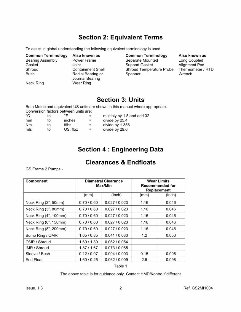
Clearances & Endfloats GS Frame 2 Pumps:- Component Diametral Clearance
Max/Min Wear Limits
Recommended for Replacement
(mm) (Inch) (mm) (Inch)
Neck Ring (2”, 50mm) 0.70 / 0.60 0.027 / 0.023 1.16 0.046
Neck Ring (3”, 80mm) 0.70 / 0.60 0.027 / 0.023 1.16 0.046
Neck Ring (4”, 100mm) 0.70 / 0.60 0.027 / 0.023 1.16 0.046
Neck Ring (6”, 150mm) 0.70 / 0.60 0.027 / 0.023 1.16 0.046
Neck Ring (8”, 200mm) 0.70 / 0.60 0.027 / 0.023 1.16 0.046
Bump Ring / OMR 1.05 / 0.85 0.041 / 0.033 1.2 0.050
OMR / Shroud 1.60 / 1.39 0.062 / 0.054 IMR / Shroud 1.87 / 1.67 0.073 / 0.065 Sleeve / Bush 0.12 / 0.07 0.004 / 0.003 0.15 0.006 End Float 1.60 / 0.25 0.062 / 0.009 2.5 0.098
Table 1
The above table is for guidance only. Contact HMD/Kontro if different
Issue. 1.3 Ref. GS2MI1004
3
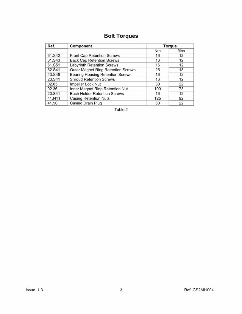
Bolt Torques
Ref. Component Torque Nm ftlbs 61.S42 Front Cap Retention Screws 16 12 61.S43 Back Cap Retention Screws 16 12 61.S51 Labyrinth Retention Screws 16 12 62.S41 Outer Magnet Ring Retention Screws 25 18 43.S49 Bearing Housing Retention Screws 16 12 20.S41 Shroud Retention Screws 16 12 02.03 Impeller Lock Nut 30 22 02.36 Inner Magnet Ring Retention Nut 100 73 20.S41 Bush Holder Retention Screws 16 12 41.N11 Casing Retention Nuts 125 92 41.50 Casing Drain Plug 30 22
Table 2

Issue. 1.3 Ref. GS2MI1004
4
Section 5 Disassembly of the GS Frame 2 Pump
Refer to the Sectional/Parts List Drawing supplied with the separate data package. Component references indicated on sectional drawings and parts list are contained in parentheses ( ) in this document.
5.01 Removal of Instrumentation If a shroud temperature probe is installed,
ensure that it is removed prior to disassembly to avoid damage when the casing is withdrawn. – Fig. 1
Fig. 1
5.02 Remove the Casing Retention Nuts (41.N11) and the Casing Retention Washers (41.W11). – Fig. 2
Fig. 2
5.03 Remove the Casing Assembly (41.41) (complete with external filter if fitted). If required use the jacking screws (43.S51) provided.
If Casing is to remain installed in pipework, unbolt mounting bolts and withdraw to clear the casing, after removing drive flexible coupling or motor.
Fig. 3

Issue. 1.3 Ref. GS2MI1004
5
5.04 Remove the three Bush Holder Retention Screws (20S41) located behind the Impeller (06.06). – Fig.3
NOTE: For pumps fitted with large Impellers, the Impeller has to be removed (see 5.06 below) to give access to the Bush Holder Retaining Screws. 5.05 Slide out the internal rotating assembly from
the Shroud (20.20). Some physical effort is required to overcome the attraction of the Inner and Outer Magnet Rings.
(37.37 and 51.51). - Figs. 4 & 5
Fig. 4
It may be easier to refit the Impeller to assist in this operation. Support this assembly as it exits the Shroud to prevent it dropping.
Fig. 5
5.06 Remove the Impeller Nut (02.03). For earlier models fitted with a Bolt and Tab Washer, straighten the Impeller Tab Washer (02.05) and remove Impeller Bolt (02.36) – Fig.6.
Do not hold or clamp IMR as this will cause permanent damage.
Fig. 6
5.07 Remove the Impeller (06.06) – Fig. 7
Take care not to drop the Thrust Washer as it is a loose fit in the back of the Impeller.
Fig. 7

Issue. 1.3 Ref. GS2MI1004
6
5.08 Slide Bush Holder (09.09) from Shaft (02.02). – Fig. 8
Due to the good surface finishes the rear Thrust Washer may adhere to the Thrust Pad. Take care not to let it fall.
Fig. 8
5.09 Remove Bush Holder Sleeve (09.22) from the Casing Plate (09.14) – Fig. 9
Fig. 9
5.10
Remove the Back Thrust Washer (08.08) and the Support Gasket (08.39) from the Pump Shaft/IMR Assembly. – Fig. 10
Removal of back thrust washer can be assisted by using a compressed air line and blowing around the edge of the washer to lift off from seat (Wear safety glasses for this method). Removal by force will cause damage to IMR (37.37) location. Fig. 10
5.11 Hold the shaft in a vice using “soft jaws” only on the area between the Silicon Carbide sleeves or by using a clamp specifically designed for the purpose. – Fig. 11
Fig. 11

Issue. 1.3 Ref. GS2MI1004
7
5.12 Turn back the tab on the Coupling Washer (02.39) and undo the Coupling Nut (02.36)
– Fig. 12 & 12A NOTE: It is a left hand thread, and should be undone in the clockwise direction.
Fig. 12
Fig. 12A
If INsight or thermal ribbon RTD sensors are installed, refer to the Insight or RTD instruction manuals before removing the Shroud. Failure to do so will damage the sensor.
5.13 Remove the two Shroud Retention Screws (20.S42). – Fig. 13
Fig 13
5.14 Remove Shroud (20.20) from the Coupling Housing (43.43). – Fig. 14 NOTE: Jacking Screws (61.S52) are provided if required.
Fig 14
Issue. 1.3 Ref. GS2MI1004
8
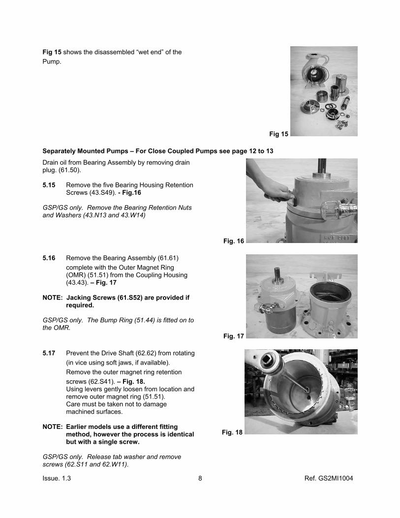
Fig 15 shows the disassembled “wet end” of the Pump.
Fig 15
Separately Mounted Pumps – For Close Coupled Pumps see page 12 to 13
Drain oil from Bearing Assembly by removing drain plug. (61.50). 5.15 Remove the five Bearing Housing Retention Screws (43.S49). - Fig.16 GSP/GS only. Remove the Bearing Retention Nuts and Washers (43.N13 and 43.W14)
Fig. 16
5.16 Remove the Bearing Assembly (61.61) complete with the Outer Magnet Ring (OMR) (51.51) from the Coupling Housing (43.43). – Fig. 17 NOTE: Jacking Screws (61.S52) are provided if required. GSP/GS only. The Bump Ring (51.44) is fitted on to the OMR.
Fig. 17
5.17 Prevent the Drive Shaft (62.62) from rotating (in vice using soft jaws, if available). Remove the outer magnet ring retention screws (62.S41). – Fig. 18. Using levers gently loosen from location and remove outer magnet ring (51.51). Care must be taken not to damage machined surfaces.
NOTE: Earlier models use a different fitting method, however the process is identical but with a single screw. GSP/GS only. Release tab washer and remove screws (62.S11 and 62.W11).
Fig. 18
Issue. 1.3 Ref. GS2MI1004
9
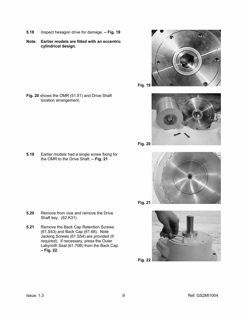
5.18 Inspect hexagon drive for damage. – Fig. 19 Note: Earlier models are fitted with an eccentric cylindrical design.
Fig. 19
Fig. 20 shows the OMR (51.51) and Drive Shaft location arrangement.
Fig. 20
5.19 Earlier models had a single screw fixing for the OMR to the Drive Shaft. – Fig. 21
Fig. 21
5.20 Remove from vice and remove the Drive Shaft key. (62.K31) 5.21 Remove the Back Cap Retention Screws (61.S43) and Back Cap (61.68). Note Jacking Screws (61.S54) are provided (if required). If necessary, press the Outer Labyrinth Seal (61.70B) from the Back Cap. – Fig. 22
Fig. 22

Issue. 1.3 Ref. GS2MI1004
10
5.22 Remove the Labyrinth Seal Retention Screw (61.S51) and remove the Inner Labyrinth Seal (61.70A). – Fig. 23 5.23 GSP/GS only. Straighten Drive Shaft Washer (62.63) and remove nut and washer.
Fig. 23
5.24 Remove the “O” Ring (61.OR1) and discard. - Fig. 24
Fig. 24
5.25 Remove the four Front Cap Retention Screws (61.S42) and remove the Front Cap (61.67) and the “O” Ring (61.OR1) as Fig. 24 above. – Fig. 25 Note: Jacking Holes are provided
Fig. 25
5.26 Using suitable levers, gently remove Front Oil Thrower (61.75). – Fig. 26
Fig. 26

Issue. 1.3 Ref. GS2MI1004
11
Fig. 27 shows the front race exposed, with the Front Oil Thrower and Front Cap.
Fig. 27
5.27 Press the Drive Shaft (62.62) from the Bearing House Assembly (61.61) - Fig. 28
Fig. 28
5.28 Press the Drive Shaft (62.62) from the Front Ball Race (62.BB1) using a suitably sized Bearing press sleeve (not supplied). – Fig. 29
Fig. 29
5.29 Clean all the dismantled components and examine for wear or damage. Any component found to be worn or damaged should be replaced with genuine spares
purchased from HMD/Kontro Sealless Pumps or their authorised representatives. Replace all joints.

Issue. 1.3 Ref. GS2MI1004
12
Close Coupled Pumps 5.30 Remove the Motor Adaptor Retention Screws
(43.S42) from the Coupling Housing and remove the Electric Motor complete with the Outer Magnet Ring (51.51) and Motor Adaptor Assembly (45.45). - Fig. 30
Fig. 30
5.31 Remove the Outer Magnet Ring retention screw (62.S41) - Fig. 31
Using levers gently loosen from location and remove Outer Magnet Ring (51.51). Care must be taken not to damage machined surfaces.
Fig. 30
5.32 Remove the Motor retention fasteners (45.S42) and separate the Motor Adaptor (45.45) from the motor. - Fig. 31
Fig. 31
5.33 Progressively loosen all the bolts on the Shrink Disc Coupling. (52.82) to avoid distortion. - Fig. 32
Fig. 33

Issue. 1.3 Ref. GS2MI1004
13
5.34 Slide the Shrink Disc Coupling (52.82) off the Drive Adaptor (52.52) towards the motor. - Fig. 34
Fig. 34
5.35 Slide the Drive Adaptor (52.52) from the motor shaft and remove the Shrink Disc Coupling (52.82). - Fig. 35
If the Drive Adaptor is tight on the shaft, gently lever off.
Fig. 35
5.36 Clean all the dismantled components and examine for wear or damage, any component found to be worn or damaged should be replaced with genuine spares purchased from HMD / Kontro Sealless Pumps or their authorised representatives.
Issue. 1.3 Ref. GS2MI1004
14
Section 6 Recommended Procedure for Replacement of Bushes and
Thrust Pads Please ensure that you conform to safe working practices.
Guard against the combustion of product residue on the component. Wear eye protection to guard against the fracturing of Carbon and Silicon Carbide Bushes and Thrust Pads. Wear suitable protective clothing and gloves while handling hot components.
6.01 It is strongly recommended that all Bushes and Thrust Pads are replaced before the pump is reassembled, if damaged or beyond wear limits given on page 3. Alternatively a new assembly can be purchased from HMD/Kontro.
Removal 6.02 If Bushes are pinned, remove the pins prior to heating the Bush Holder. Remove existing Thrust Pad
(09.13) in an oven at 350°C (662°F). At this temperature the Bushes and Thrust Pad can be easily removed.
Fitting Clean mating bores and faces thoroughly prior to fitting of replacement parts. Use a non mechanical cleaning method. Note: Metal blocks will be required, refer to Section 1 (Page 2) Tool Requirements. 6.03 For new Bushes (09.10 & 09.10A) and the Back Thrust Pad (09.13) place them in to an oven and
hold within 50°C (122°F) of the Bush Holder temperature and maintain for approximately 30 minutes, prior to fitting the Bush Holder. This is not required for Carbon Bushes. Metal blocks should also be preheated to prevent cracking of the Bush and Thrust Pad.
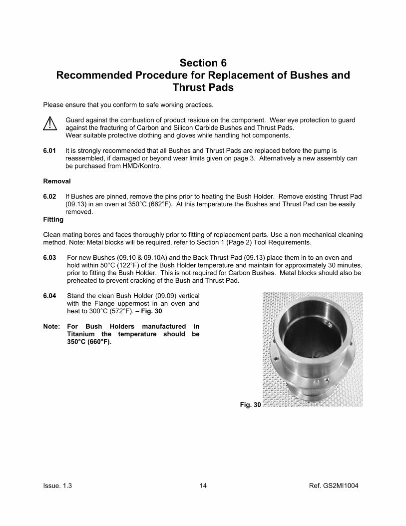
6.04 Stand the clean Bush Holder (09.09) vertical
with the Flange uppermost in an oven and heat to 300°C (572°F). – Fig. 30
Note: For Bush Holders manufactured in Titanium the temperature should be 350°C (660°F).
Fig. 30
Issue. 1.3 Ref. GS2MI1004
15
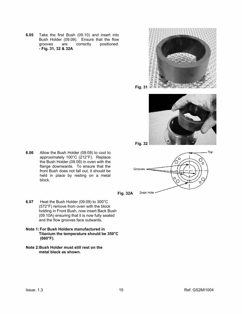
6.05 Take the first Bush (09.10) and insert into
Bush Holder (09.09). Ensure that the flow grooves are correctly positioned. - Fig. 31, 32 & 32A
Fig. 31
Fig. 32
6.06 Allow the Bush Holder (09.09) to cool to approximately 100°C (212°F). Replace the Bush Holder (09.09) in oven with the flange downwards. To ensure that the front Bush does not fall out, it should be held in place by resting on a metal block.
Fig. 32A
6.07 Heat the Bush Holder (09.09) to 300°C (572°F) remove from oven with the block holding in Front Bush, now insert Back Bush (09.10A) ensuring that it is now fully seated and the flow grooves face outwards. Note 1: For Bush Holders manufactured in Titanium the temperature should be 350°C (660°F). Note 2:Bush Holder must still rest on the metal black as shown.
Issue. 1.3 Ref. GS2MI1004
16
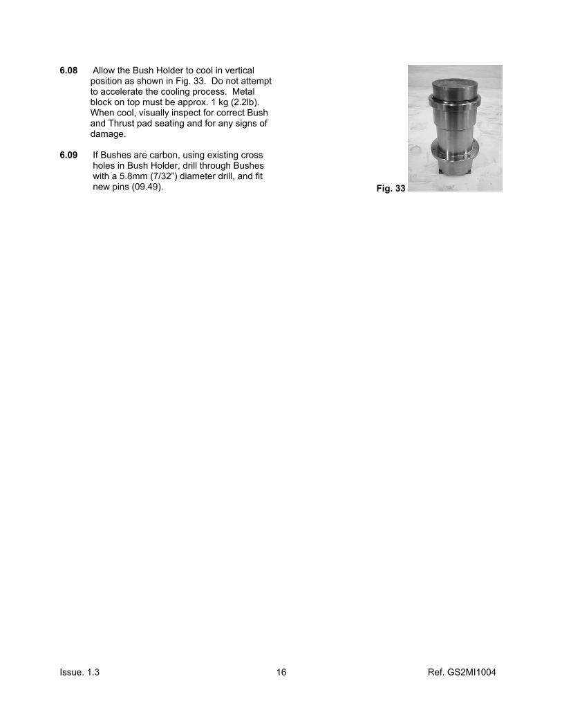
6.08 Allow the Bush Holder to cool in vertical position as shown in Fig. 33. Do not attempt to accelerate the cooling process. Metal block on top must be approx. 1 kg (2.2lb). When cool, visually inspect for correct Bush and Thrust pad seating and for any signs of damage. 6.09 If Bushes are carbon, using existing cross holes in Bush Holder, drill through Bushes with a 5.8mm (7/32”) diameter drill, and fit new pins (09.49). Fig. 33
Issue. 1.3 Ref. GS2MI1004
17
Section 7 Neck Ring and Impeller Wear Ring Replacement
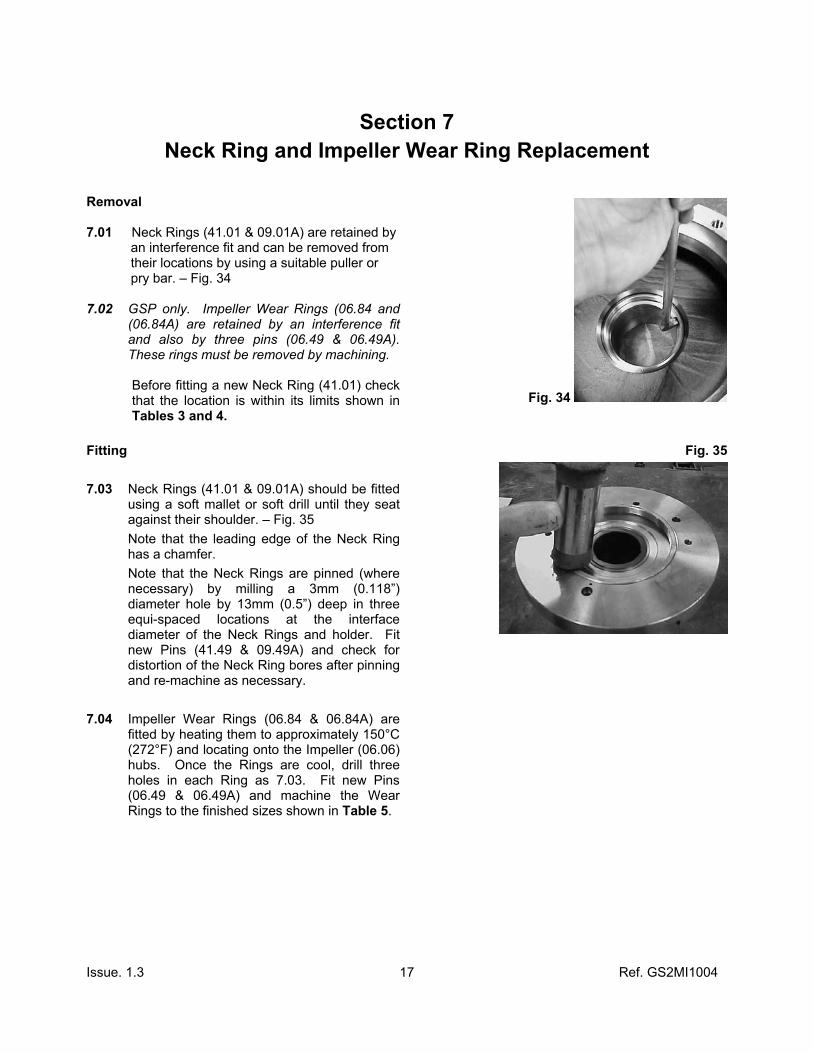
Removal 7.01 Neck Rings (41.01 & 09.01A) are retained by an interference fit and can be removed from their locations by using a suitable puller or pry bar. – Fig. 34 7.02 GSP only. Impeller Wear Rings (06.84 and
(06.84A) are retained by an interference fit and also by three pins (06.49 & 06.49A). These rings must be removed by machining.
Before fitting a new Neck Ring (41.01) check that the location is within its limits shown in Tables 3 and 4.
Fig. 34
Fitting 7.03 Neck Rings (41.01 & 09.01A) should be fitted
using a soft mallet or soft drill until they seat against their shoulder. – Fig. 35 Note that the leading edge of the Neck Ring has a chamfer. Note that the Neck Rings are pinned (where necessary) by milling a 3mm (0.118”) diameter hole by 13mm (0.5”) deep in three equi-spaced locations at the interface diameter of the Neck Rings and holder. Fit new Pins (41.49 & 09.49A) and check for distortion of the Neck Ring bores after pinning and re-machine as necessary.
7.04 Impeller Wear Rings (06.84 & 06.84A) are fitted by heating them to approximately 150°C (272°F) and locating onto the Impeller (06.06) hubs. Once the Rings are cool, drill three holes in each Ring as 7.03. Fit new Pins (06.49 & 06.49A) and machine the Wear Rings to the finished sizes shown in Table 5.
Fig. 35

Issue. 1.3 Ref. GS2MI1004
18
Neck Ring Location Bore
GSA/I
Pump Size Casing Inchmm
Bush Holder Inchmm
3x2x8 4.017 / 4.016 102.035 / 102.000
4.804 / 4.803 122.040 / 122.000
2x1x10 50-32-250
3.190 / 3.189 81.035 / 81.000
5.907 / 5.906 150.040 / 150.000
3x1.5x10 65-40-250
4.017 / 4.016 102.035 / 102.000
5.907 / 5.906 150.040 / 150.000
3x2x10 80-50-250
4.017 / 4.016 102.035 / 102.000
5.907 / 5.906 150.040 / 150.000
4x3x6 100-80-160
4.804 / 4.803 122.040 / 122.000
4.804 / 4.803 122.040 / 122.000
4x3x8 100-65-200
4.804 / 4.803 122.040 / 122.000
5.907 / 5.906 150.040 / 150.000
4x3x10 100-65-250
4.804 / 4.803 122.040 / 122.000
5.907 / 5.906 150.040 / 150.000
6x4x8 125-80-200
5.907 / 5.906 150.040 / 150.000
4.804 / 4.803 122.040 / 122.000
3x1.5x13 65-40-315
4.332 / 4.331 110.035 / 110.000
5.907 / 5.906 150.040 / 150.000
3x2x13 80-50-315
4.332 / 4.331 110.035 / 110.000
5.907 / 5.906 150.040 / 150.000
4x3x13 100-65-315
5.198 / 5.197 132.040 / 132.000
5.907 / 5.906 150.040 / 150.000
6x4x10 125-100-250
6.458 / 6.457 164.040 / 164.000
5.907 / 5.906 150.040 / 150.000
2x1x13 50-32-315
3.190 / 3.189 81.035 / 81.000
5.907 / 5.906 150.040 / 150.000
6x4x13 125-100-315
6.458 / 6.457 164.040 / 164.000
5.907 / 5.906 150.040 / 150.000
8x6x11.5 200-150-300
8.859 / 8.858 225.030 / 225.00
5.907 / 5.906 150.040 / 150.000
Table 3

Issue. 1.3 Ref. GS2MI1004
19
Neck Ring Location Bore
GSP/GS
Pump Size Casing Inchmm
Bush Holder Inchmm
3x2x8 4.411 / 4.409 112.035 / 112.000
4.804 / 4.803 122.040 / 122.000
2x1x10 3.584 / 3.583 91.035 / 91.000
5.907 / 5.906 150.040 / 150.000
3x1.5x10 4.411 / 4.409 112.035 / 112.000
5.907 / 5.906 150.040 / 150.000
3x2x10 4.411 / 4.409 112.035 / 112.000
5.907 / 5.906 150.040 / 150.000
4x3x6 5.198 / 5.197 132.040 / 132.000
4.804 / 4.803 122.040 / 122.000
4x3x8 5.198 / 5.197 132.040 / 132.000
4.804 / 4.803 122.040 / 122.000
4x3x10 5.198 / 5.197 132.040 / 132.000
5.907 / 5.906 150.040 / 150.000
6x4x8 6.301 / 6.299 160.040 / 160.000
4.804 / 4.803 122.040 / 122.000
3x1.5x13 4.805 / 4.803 122.035 / 122.000
5.907 / 5.906 150.040 / 150.000
3x2x13 4.726 / 4.724 120.035 / 120.000
5.907 / 5.906 150.040 / 150.000
4x3x13 5.592 / 5.591 142.040 / 142.000
5.907 / 5.906 150.040 / 150.000
6x4x10 6.852 / 6.850 174.040 / 174.000
5.907 / 5.906 150.040 / 150.000
2x1x13 3.584 / 3.583 91.035 / 91.000
5.907 / 5.906 150.040 / 150.000
6x4x13 6.852 / 6.850 174.040 / 174.000
5.907 / 5.906 150.040 / 150.000
8x6x11.5 8.859 / 8.858 225.030 / 225.00
5.907 / 5.906 150.040 / 150.000
8x6x13 9.450 / 9.448 240.046 / 240.000
5.907 / 5.906 150.040 / 150.000
Table 4

Issue. 1.3 Ref. GS2MI1004
20
Finished Machined Impeller Wear Ring Outer Diameter
GSP
Pump Size Front Wear Ring Inchmm
Rear Wear Ring Inchmm
3x2x8 3.976 / 3.974 101.00 / 100.95
4.370 / 4.368 111.00 / 110.95
2x1x10
3.150 / 3.148 80.00 / 79.95
5.394 / 5.392 137.00 / 136.95
3x1.5x10
3.976 / 3.974 101.00 / 100.95
5.394 / 5.392 137.00 / 136.95
3x2x10
3.976 / 3.974 101.00 / 100.95
5.394 / 5.392 137.00 / 136.95
4x3x6
4.764 / 4.762 121.00 / 120.95
4.370 / 4.368 111.00 / 110.95
4x3x8
4.764 / 4.762 121.00 / 120.95
4.370 / 4.368 111.00 / 110.95
4x3x10 4.764 / 4.762 121.00 / 120.95
5.394 / 5.392 137.00 / 136.95
6x4x8
5.866 / 5.864 149.00 / 148.95
4.370 / 4.368 111.00 / 110.95
3x1.5x13
4.370 / 4.368 111.00 / 110.95
5.394 / 5.392 137.00 / 136.95
3x2x13
4.370 / 4.368 111.00 / 110.95
5.394 / 5.392 137.00 / 136.95
4x3x13
5.118 / 5.116 130.00 / 129.95
5.394 / 5.392 137.00 / 136.95
6x4x10
6.417 / 6.415 163.00 / 162.95
5.394 / 5.392 137.00 / 136.95
2x1x13
3.150 / 3.148 80.00 / 79.95
5.394 / 5.392 137.00 / 136.95
6x4x13
6.024 / 6.022 153.00 / 152.95
5.394 / 5.392 137.00 / 136.95
8x6x11.5
8.791 / 8.79 223.30 / 223.25
5.394 / 5.392 137.00 / 136.95
8x6x13
8.791 / 8.79 223.30 / 223.25
5.394 / 5.392 137.00 / 136.95
Table 5

Issue. 1.3 Ref. GS2MI1004
21
SECTION 8 Assembly Instructions for the
GS Frame 2 Pump Ensure that the Pump Components have been cleaned and are in an “as new” condition before assembly. The assembly should be carried out in a clean, dry area. Separate Mounted Pumps 8.01 Install the Front Ball Race (62.BB1) to the
Drive Shaft by either pressing or pre-heating the race. Ensure it is seated against the location shoulder on the shaft (62.62). – Fig. 36
Fig. 36
8.02 Insert the Drive Shaft (62.62) into the Bearing Housing (61.61) and gently tap or press the Outer Ball Race of Bearing until it is seated against the location shoulder in the Bearing Housing (61.61).
Replace the Front Oil Thrower (61.75). - Fig. 37
Fig. 37
8.03 Replace the Front Cap (61.67) c/w new “O” Ring (61.OR1) and retain with Retention Screws (61.S43). Torque to 16 Nm, (12 ft.lbs). – Fig. 38
Fig. 38

Issue. 1.3 Ref. GS2MI1004
22
8.04 Place the Rear Ball Race (62.BB1) on to the Drive Shaft (62.62) and into the Bearing Housing (61.61). – Fig. 39
Fig. 39
8.05 Drive Shaft and Rear Race Assembly can be located on Bearing Housing shoulder by use of a press. – Fig. 40
GSP/GS only. To lock nut, fit Drive Shaft Washer (62.64) and Drive Shaft Nut (62.63) to the Drive Shaft (62.62) and tighten to 50Nm, 37 ft.lbs turning Tab Washer over on to one flat of the nut.
Fig. 40
8.06 Install the new ‘O’ Ring (61.OR1) into the rear of the Bearing Housing (61.61). – Fig. 41
Fig. 41
8.07 Install the new rear ‘O’ Ring (62.OR2) to the bore of the inner Labyrinth Seal (61.70A) and slide onto the Drive Shaft (62.62) up to the shoulder. Align retention hole with flat on Drive Shaft, tighten the Labyrinth Retention Screw on the Drive Shaft. Torque to 16 Nm, (12 ft.lbs) (61.S51). – Fig. 42
Fig. 42

Issue. 1.3 Ref. GS2MI1004
23
8.08 Press Outer Labyrinth Seal (61.70B) into the Back Cap (61.68) ensuring the hole in to seal is in-line with the slot on the inside of the Back Cap. 8.09 Secure the Back Cap (61.68) into the
Bearing Housing (61.61). Torque to 16 Nm, (12 ft.lbs) (61.S51).
Fig. 43
Close Coupled Pumps
8.10 Install Shrink Disc Coupling (52.82) and
Drive Flange Adaptor (52.52) over Motor Shaft with bolts towards motor, ensure that Adaptor is fully seated against Motor Shaft end. Torque bolts progressively in a sequential order around the circumference. - Table 5
The required torque value for the Shrink Disc coupling, are shown in chart below or as indicated on the coupling. - Fig. 44
Do not tighten bolts diagonally
Fig. 44
Motor Frame Size Torque Nm Ft lbs 143T, 145T, 90S, 90L. 4 3
182T, 184T, 213T, 215T, 254T, 256T, 284T, 286T, 324T, 326T, 100L,112M, 132S, 132M, 160L, 160M, 180L, 180M, 200L
12 9
Table 5
8.11 Fit Motor Adaptor (45.45) to Motor Face/Flange and bolt to correct torque. - Fig. 45
Fig. 45

Issue. 1.3 Ref. GS2MI1004
24
8.12 Fit Coupling Housing to the Motor Adaptor and retain with the retention fasteners (45.S42). Torque to 12 Nm (9 ft lbs). If new Bump Ring (43.44) is required refer to 8.11.
All Pumps 8.13 Install the Outer Magnet Ring (OMR) (51.51)
on to its location and tighten the Outer Magnet Ring Retention Screws (62.S41) to a torque of 25Nm, (18 ft.lbs) after applying thread lock to screw. (Earlier models only use one screw). – Fig. 44
GSP/GS only. If new Bump Ring (51.44) is Required, slide Bump Ring over front of Outer Magnet Ring (51.51), and gently tap into position using a soft drive before fitting to Drive Shaft. GSP/GS only. Turn Tab Washer into hole in Outer Magnet Ring (OMR) and tighten the OMR Retention Screw to a torque of 25 Nm, (18 ft.lbs) (62.W11 and 62.S11) turn Tab Washer onto one flat of Bolt.
Fig. 44
8.11 If required insert a new Bump Ring (43.44) to the Coupling Housing (43.43) by gently tapping into place using a soft drift. – Fig. 45
Fig. 45
Issue. 1.3 Ref. GS2MI1004
25
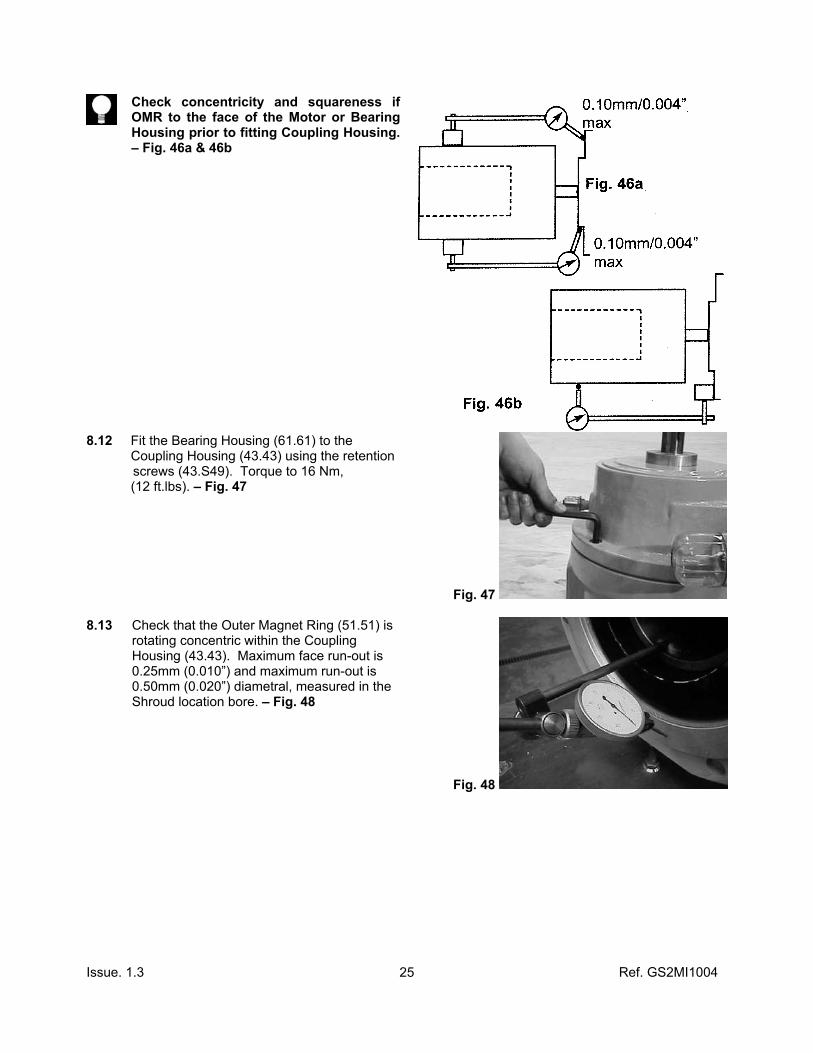
Check concentricity and squareness if OMR to the face of the Motor or Bearing Housing prior to fitting Coupling Housing. – Fig. 46a & 46b
8.12 Fit the Bearing Housing (61.61) to the Coupling Housing (43.43) using the retention screws (43.S49). Torque to 16 Nm, (12 ft.lbs). – Fig. 47
Fig. 47
8.13 Check that the Outer Magnet Ring (51.51) is rotating concentric within the Coupling Housing (43.43). Maximum face run-out is 0.25mm (0.010”) and maximum run-out is 0.50mm (0.020”) diametral, measured in the Shroud location bore. – Fig. 48
Fig. 48

Issue. 1.3 Ref. GS2MI1004
26
8.14 If instrumentation is to be fitted refer to the appropriate manual.
8.15 Install the Shroud (20.20) into the Coupling
Housing (43.43) using the two Shroud Retention Screws (20.S42). Torque screws to 16 Nm (12 ft.lbs). – Fig. 49
Fig. 49
8.16 Install two new ‘O’ Rings (02.0R1) into the grooves in the Impeller end of the Pump Shaft (02.02). – Fig. 50
Fig. 50
8.17 Install in a twisting motion to Front Pump Shaft Sleeve (02.86) onto the Pump Shaft until it seats. – Fig. 51
8.18 Install two new ‘O’ Rings (02.0R1) into the two remaining grooves on the Pump Shaft. (02.02).
Fig. 51
8.19 Install remaining shaft sleeve as 8.17. 8.20 Secure the Shaft in a vice, using a form of “soft jaws” to prevent damage. – Fig. 52
Fig. 52
Issue. 1.3 Ref. GS2MI1004
27
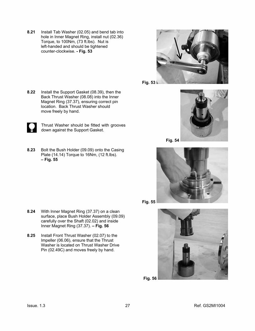
8.21 Install Tab Washer (02.05) and bend tab into hole in Inner Magnet Ring, install nut (02.36) Torque, to 100Nm, (73 ft.lbs). Nut is left-handed and should be tightened counter-clockwise. - Fig. 53
Fig. 53
8.22 Install the Support Gasket (08.39), then the Back Thrust Washer (08.08) into the Inner Magnet Ring (37.37), ensuring correct pin location. Back Thrust Washer should move freely by hand.
Thrust Washer should be fitted with grooves down against the Support Gasket.
Fig. 54
8.23 Bolt the Bush Holder (09.09) onto the Casing Plate (14.14) Torque to 16Nm, (12 ft.lbs). – Fig. 55
Fig. 55
8.24 With Inner Magnet Ring (37.37) on a clean surface, place Bush Holder Assembly (09.09) carefully over the Shaft (02.02) and inside Inner Magnet Ring (37.37). – Fig. 56 8.25 Install Front Thrust Washer (02.07) to the Impeller (06.06), ensure that the Thrust Washer is located on Thrust Washer Drive Pin (02.49C) and moves freely by hand.
Fig. 56

Issue. 1.3 Ref. GS2MI1004
28
8.26 Fit Impeller to the Shaft (02.02) and replace the Impeller Fastener (02.03) and a new Impeller Tab Washer (02.05A) [only for early models – on later models this is an Impeller Nut (02.03)]. – Fig. 57
Note: If building vertically care must be taken to ensure that the Front Thrust Washer (02.07) does not fall out of the Impeller.
Fig. 57
8.27 Holding the Impeller (06.06) securely tighten the Impeller Fastener to 30 Nm, (22 ftlbs).
– Fig. 58
Fig. 58
8.28 Check that the Shaft Assembly rotates freely within the Bush Holder then bend the new Coupling Tab Washer (02.05) into contact with one of the flats on the Coupling Nut (02.36).
8.29 Hold on outside of Impeller and Impeller eye
and slide the Assembly into the Shroud (20.20). Care must be taken as there will be strong magnetic attraction between the Inner and Outer Magnet Rings. – Fig. 59
Fig. 59
8.30 Secure the Bush Holder (09.09) to the Shroud (20.20) using the three Retention Screws (20.S41). Torque to 16 Nm,
(12 ft.lbs). Note: Align holes prior to fitting screws. – Fig. 60
Fig. 60
Issue. 1.3 Ref. GS2MI1004
29
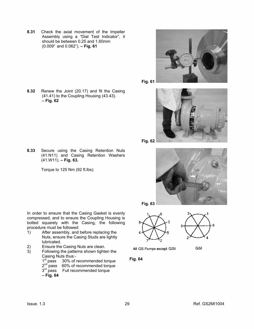
8.31 Check the axial movement of the Impeller Assembly using a “Dial Test Indicator”, it should be between 0.25 and 1.60mm
(0.009” and 0.062”). – Fig. 61
Fig. 61
8.32 Renew the Joint (20.17) and fit the Casing (41.41) to the Coupling Housing (43.43).
– Fig. 62
Fig. 62
8.33 Secure using the Casing Retention Nuts (41.N11) and Casing Retention Washers (41.W11). – Fig. 63.
Torque to 125 Nm (92 ft.lbs).
Fig. 63
In order to ensure that the Casing Gasket is evenly compressed, and to ensure the Coupling Housing is bolted squarely with the Casing, the following procedure must be followed: 1) After assembly, and before replacing the
Nuts, ensure the Casing Studs are lightly lubricated.
2) Ensure the Casing Nuts are clean. 3) Following the patterns shown tighten the
Casing Nuts thus:- 1st pass 30% of recommended torque 2nd pass 60% of recommended torque 3rd pass Full recommended torque – Fig. 64
Fig. 64

Issue. 1.3 Ref. GS2MI1004
30
8.34 Fit Casing Drain Plug (41.50). Always use a new gasket (41.17). Torque to 30 Nm
(22 ft.lbs). 8.35 Ensure either the temperature monitoring
(41.TC) device or plug (41.50B) is fitted. 8.36 Ensure all unused connections are plugged. 8.37 The pump is now ready for hydrostatic and
performance testing. – Fig. 65 Fig. 65
8.38 Fit the Adaptor (61.CL2) to the Constant Level Oiler (61.CL1) via the tapered thread. Fit the Union (61.CL3) and Washer to the Adaptor and then the whole assembly to the Bearing Housing (61.61). Ensure the bottle is vertical. Do not fill oil bottle at this stage. Where sealed for life grease bearings are fitted, do not fit the constant level oiler and associated fittings, fit a plug instead.

Issue. 1.3 Ref. GS2MI1004
31
SECTION 9 Oil Lubricated Bearing Assemblies
Separate Mounted Only
9.01 Filling Procedure This details the filling procedure for oil lubricated bearing assemblies.
Do not fill using the coupling housing vent plug shown in Fig. 66, as this will place oil in the coupling housing and may lead to pump failure.
Fig. 66
Fill the oil lubricated bearing assembly using a recommended grade of oil, stated in section 9.02, by removing the filter/breather (61.VP1), and pouring approximately three quarters of the volume of oil, stated in section 9.03, into the housing. The remaining volume, to ensure the correct oil level, should be filled using the oil bottle as follows:- Fill the oil bottle and place in the constant level oiler (61.CL1) allow the bottle to empty which may take 15 minutes or so, and then refill and repeat the procedure. If the oil bottle does not empty or stops at the same level for 30 minutes or so, the correct oil level in the bearing housing has been reached. Do not try to take short cuts by topping up via the breather or constant level oiler without the bottle fitted, as this may result in overfilling, resulting in oil entering the coupling housing, or hot running bearings. GSP/GS only. Bearing housings are fitted with a window nut. The correct oil level is half way up the window.

Issue. 1.3 Ref. GS2MI1004
32
9.02 Recommended Oil Grades Typical Physical Characteristics Acceptance Method ISO Oil Type HM - ISO Viscosity grade 68 - Viscosity, kinematic at 0°C at 40° at 100°
1040 (max) 64-68 8.6 (max)
ASTM D445 Or IP71
Viscosity Index 98-102 ASTM D2270 or IP226 Density at 15°, Kg/ m3 878-888 ASTM D4052 or IP365 Flash Point °C (Pensky-Martens Closed Cup/coc) 220-255 ASTM D92 or IP365 Pour Point °C -5 to -30 ASTM D97 or IP15 Foaming Characteristics ml, after 10 minutes
Sequence 1 @ 24°C Tendency/Stability Trace/Nil ASTM D892 or IP146 Sequence 2 @ 93.5°C Tendency/Stability 20/Nil Sequence 3 @ 24°C (after sequence 2) Tendency/Stability Trace/Nil For equipment operating in ambient temperatures below - 40°C (- 40°F) consult HMD/Kontro for advice. For pumps operating in process temperatures above 260°C (500°F) a synthetic oil is recommended. Consult HMD/Kontro for advice.

Issue. 1.3 Ref. GS2MI1004
33
9.03 Oil Capacities (Power Frame Housing)
Quantities are in ml and US fl. Ozs and are approximate. To determine how much oil is required for your particular pump, refer to the model number on either the order acknowledgement or the nameplate fitted to the pump. With that information refer to the tables below for the correct amount of oil needed. If you have any doubts or questions, please do not hesitate to contact HMD/Kontro or your local representative.
GSA GSP/GS GSI Size mls US
fl.oz mls US
fl.oz
Size
mls US fl.oz
4x3x6 3x2x8 4x3x8H 6x4x8H 2x1x10 3x1.5x10 3x2x10 4x3x10 6x4x10 2x1x13 3x1.5x13 3x2x13 4x3x13
200 200 200 200 200 200 200 200 200 200 200 200 200
6.6 6.6 6.6 6.6 6.6 6.6 6.6 6.6 6.6 6.6 6.6 6.6 6.6
740 740 740 740 740 740 740 740 740 740 740 740 740
24.5 24.5 24.5 24.5 24.5 24.5 24.5 24.5 24.5 24.5 24.5 24.5 24.5
100-80-160 100-65-200 125-80-200 50-32-250 65-40-250 80-50-250 100-65-200 125-100-250 50-32-315 65-40-315 80-50-315 100-65-315 125-100-315
125 125 125 125 125 125 125 125 125 125 125 125 125
4.1 4.1 4.1 4.1 4.1 4.1 4.1 4.1 4.1 4.1 4.1 4.1 4.1

Issue. 1.3 Ref. GS2MI1004
34

Issue. 1.3 Ref. GS2MI1004
35
Your Local Agent
Quality Assured since 1985 for the Design, Manufacture and Repair of
Sealless Pumps and Drives HMD Seal/less Pumps Ltd Hampden Park Industrial Estate, Eastbourne, East Sussex, BN22 9AN, ENGLAND. Tel: +44 (0) 1323 452000 Fax: +44 (0) 1323 503369 e mail: [email protected] web: www.hmdkontro.com