Model 3408A - Goulds Pumps · The 3408A centrifugal pumps are frame mounted pumps which feature...
44
Installation, Operation and Maintenance Instructions Model 3408A AC8744
Transcript of Model 3408A - Goulds Pumps · The 3408A centrifugal pumps are frame mounted pumps which feature...

Installation, Operation and Maintenance Instructions
Model 3408A
AC8744


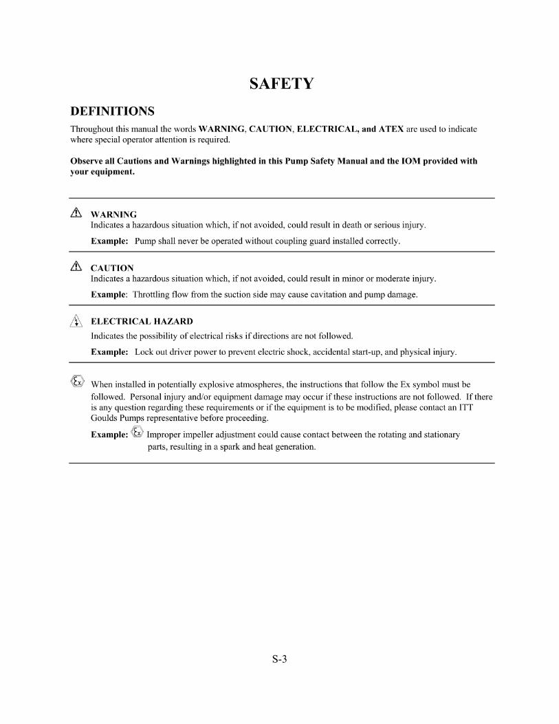


TABLE OF CONTENTSPAGE
5 INTRODUCTION
7 SAFETY
11 GENERAL INSTRUCTIONS
19 OPERATION
3408A IOM 6/08 3
1
3
4
2
SECTION

4 3408A IOM 6/08

INTRODUCTIONDESCRIPTIONThe 3408A centrifugal pumps are frame mounted pumpswhich feature high efficiency, rugged construction,compact design, foot mounted volute, center drop outcoupler, and regreasable bearings. These features, alongwith the horizontal split case make installation, operation,and service easy to perform.
PUMP APPLICATIONThe standard 3408A centrifugal pump’s bronze fittedconstruction make it ideal for service with the followingliquids: unheated domestic and fresh water, boiler feedwater, condensate, hydronic cooling or heating, pressureboosting, general pumping and benign liquids.
For other applications contact your local Goulds PumpsPump representative.
OPERATIONAL LIMITSUnless special provisions have been made for your pumpby Goulds Pumps, the operational limits for 3408A Pumpsare as follows:
175# Maximum Working Pressure
75# Maximum Suction Pressure
Listed on pump nameplate.
SEAL OPERATING LIMITSStandard Self Flushing Mechanical Seals
BUNA-PH Limitations 7-9; Temperature Range -20 to+225°F
EPT-PH Limitations 7-11; Temperature Range -20 to+250°F
For use on closed or open systems which are relatively freeof dirt and/or other abrasive particles.
PUMP IDENTIFICATIONPumps are designated by a series of numbers such as3408A. The pump nameplate gives identification and ratinginformation as identified in Figure 1.
Permanent records for this pump are kept by serial numberand it must be used with all correspondence and spare partsorders.
The frame plate shown in Figure 1A, gives informationconcerning the bearings and their lubrication. The inboardand outboard bearing numbers refer to the bearingmanufacturer’s numbers.
Figure 1: Rating Plate
Figure 2: Frame Plate
3408A IOM 6/08 5
1

6 3408A IOM 6/08

SAFETY�! SAFETY INSTRUCTION
This safety alert symbol will be used in this manual andon the pump safety instruction decals to draw attentionto safety related instructions. When used, the safetyalert symbol means Attention! Become Alert! YourSafety Is Involved!
Failure to follow the instructions may result in asafety hazard.
Your 3408A pump should have the safety instructiondecals in Figure 2 displayed. If the decals are missing orillegible, contact your local Goulds Pumps representativefor a replacement.
Figure 2: Safety Instruction Decals
3408A IOM 6/08 7
2

ADDITIONAL SAFETY INSTRUCTIONS
1. Electrical connections to be made by qualifiedelectrician in accordance with all national, state, andlocal codes.
2. Motor must have properly sized starter with properlysized heaters to provide overload and undervoltageprotection.
3. If pump, motor, or piping is operating at extremelyhigh or low temperatures, guarding or insulation isrequired.
4. The maximum working pressure of the pump is listedon the pump nameplate; do not exceed this pressure.
Electrical Safety
�! WARNINGElectrical Shock Hazard
Electrical connections to be made by a qualified electri-cian in accordance with all applicable codes, ordi-nances, and good practices.
Failure to follow these instructions could result in seri-ous personal injury or death, or property damage.
�! WARNINGElectrical Overload Hazard
Three-phase motors must have properly sized heaters toprovide overload and under voltage protection. Sinle-phase motors have built-in overload protectors.
Failure to follow these instructions could result inserious personal injury or death, or property damage.
Thermal Safety
�! WARNINGExtreme Temperature Hazard
If pump, motor, or piping is operating at extremelyhigh or low temperatures, guarding or insulation isrequired.
Failure to follow these instructions could result inserious personal injury or death, or property damage.
Mechanical Safety
�! WARNINGUnexpected Startup Hazard
Disconnect and lockout power before servicing.
Failure to follow these instructions could result inserious personal injury or death, or property damage.
�! WARNINGExcessive System Pressure Hazard
The maximum working pressure of the pump is listedon the nameplate. Do not exceed this pressure.
Failure to follow these instructions could result inserious personal injury or death, or property damage.
�! WARNINGExcessive Pressure Hazard
Volumetric Expansion
The heating of water and other fluids causesvolumetric expansion. The associated forces may causefailure of system components and release of hightemperature fluids. This will be prevented by installingproperly sized and located compression tanks andpressure relief valves.
Failure to follow these instructions could result inserious personal injury or death, or property damage.
8 3408A IOM 6/08

LOCATION
Locate the pump so there is sufficient room for inspection,maintenance, and service. If the use of a hoist or tackle isneeded, allow ample head room.
�! WARNINGFalling Objects Hazard
Eyebolts or lifting lugs, if provided are for lifting onlythe components to which they are attached.
Failure to follow these instructions could result inserious personal injury or death, or property damage.
If lifting of the entire pump is required, do so with slingsplaced under the base rails as shown in Figure 3.
The best pump location for sound and vibration absorptionis on a concrete floor with subsoil underneath. If the pumplocation is overhead, special precautions should beundertaken to reduce possible sound transmission. Consulta sound specialist.
If the pump is not on a closed system, it should be placed asnear as possible to the source of the liquid supply andlocated to permit installation with the fewest number ofbends or elbows in the suction pipe.
Figure 3: Lifting the Pump
The installation must be evaluated to determine that the NetPositive Suction Head Available (NPSHA) meets orexceeds the Net Positive Suction Head Required (NPSHR),as stated by the pump performance curve. See the sectionentitled Suction and Discharge Piping for more detailsregarding proper suction piping installation.
�! WARNINGDo not install and operate pumps, 3D valves, suctiondiffusers, etc., in closed systems unless the system isconstructed with properly sized safety devices andcontrol devices. Such devices include the use ofproperly sized and located pressure relief valves,compression tanks, pressure controls, temperaturecontrols, and flow controls as appropriate. If thesystem does not include these devices, consult theresponsible engineer or architect before making pumpsoperational.
3408A IOM 6/08 9
2

10 3408A IOM 6/08

GENERAL INSTRUCTIONSPURPOSE OF THE MANUALThis manual is furnished to acquaint you with some of thepractical ways to install, operate, and maintain this pump.Read it completely before any installation, operation, ormaintenance on your unit and keep it handy for futurereference.
Equipment cannot operate well without proper care. Tokeep this unit at top efficiency, follow the recommendedinstallation and servicing procedures outlined in thismanual.
WARRANTYRefer to your local representative for warranty coverage.
RECEIVING THE PUMPCheck the pump for shortages and damage immediatelyupon arrival. (An absolute must!) Prompt reporting of anydamage to the carrier’s agent, with notations made on thefreight bill, will expedite satisfactory adjustment by thecarrier.
Pumps and drivers are normally shipped from the factorymounted on a base plate and painted with primer and onefinish coat. Couplings may either be completely assembledor have the coupling hubs mounted on the shafts and theconnecting members removed. When the connectingmembers are removed, they will be packaged in a separatecontainer and shipped with the pump or attached to the baseplate.
Shafts are in alignment when the unit is shipped; however,due to shipping, the pumps may arrive misaligned.Alignment must be established during installation. GouldsPumps has determined that proper and correct alignmentcan only be made by accepted erection practices. (See theFoundation, Baseplate Setting, and Coupling Alignmentsections.)
TEMPORARY STORAGEIf the pump is not to be installed and operated soon afterarrival, store it in a clean, dry place having slow, moderatechanges in ambient temperature. Rotate the shaftperiodically to coat the bearings with lubricant, to retardoxidation and corrosion, and to reduce the possibility offalse brinelling of the bearings.
LOCATIONThe pump should be installed as near the suction supply aspossible, but no less than five suction diameters with theshortest and most direct suction pipe practical. See thesection entitled Suction and Discharge Piping. The totaldynamic suction lift (static lift plus friction losses in suction
line) should not exceed the limits for which the pump wassold.
The pump must be primed before starting. Wheneverpossible, the pump should be located below the fluid levelto facilitate priming and assure a steady flow of liquid. Thiscondition provides a positive suction head on the pump. Itmay also be possible to prime the pump by pressurizing thesuction vessel.
When installing the pump, consider its location in relationto the system to assure that sufficient Net Positive SuctionHead (NPSH) at pump suction is provided. AvailableNPSH must always equal or exceed the required NPSH ofthe pump.
The pump should be installed with sufficient accessibilityfor inspection and maintenance. A clear space with amplehead room should be allowed for the use of an overheadcrane or hoist sufficiently strong to lift the unit.
NOTE: Allow sufficient space to be able to dismantlethe pump without disturbing the pump inlet anddischarge piping.
Select a dry place above the floor level wherever possible.Take care to prevent the pump from freezing during coldweather when not in operation. Should the possibility offreezing exist during a shut-down period, the pump should becompletely drained, and all passages and pockets where liquidmight collect should be blown out with compressed air.
Make sure there is a suitable power source available for thepump driver. If motor driven, electrical characteristicsshould be identical to those shown on the motor data plate.
FOUNDATIONA substantial foundation and footing should be built to suitlocal conditions. It should form a rigid support to maintainalignment. The pump assembly must be mounted to a
suitable foundation having a mass � 1.5 times the weight ofthe unit.
The foundation should be poured without interruption towithin 1/2 to 1-1/2 inches of the finished height. The topsurface of the foundation should be well scored andgrooved before the concrete sets; this provides a bondingsurface for the grout.
Foundation bolts should be set in concrete as shown inFigure 4. An optional 4-inch long tube around the bolts atthe top of the concrete will allow some flexibility in boltalignment to match the holes in the base plate. Allowenough bolt length for grout, shims, lower base plateflange, nuts and washers. The foundation should beallowed to cure for several days before the baseplate is
3408A IOM 6/08 11
3

shimmed and grouted.
Figure 4: Foundation
BASEPLATE SETTING (BEFOREPIPING)
NOTE: This procedure assumes that a concretefoundation has been prepared with anchor or holddown bolts extending up ready to receive unit. It mustbe understood that pump and motor have beenmounted and rough aligned at the factory. If motor isto be field mounted, consult factory for recommenda-tions. Goulds Pumps cannot assume responsibility forfinal alignment.
Figure 5: Setting Baseplate and Grouting
1. Use blocks and shims under base for support at anchorbolts and midway between bolts, to position baseapproximately 1 inch above the concrete foundation,with studs extending through holes in the baseplate.
2. By adding or removing shims under the base, level andplumb the pump shaft and flanges.
3. Draw anchor nuts tight against base, and observe pumpand motor shafts or coupling hubs for alignment.(Temporarily remove coupling guard for checkingalignment.)
4. If alignment needs improvement, add shims or wedgesat appropriate positions under base, so that retighteningof anchor nuts will shift shafts into closer alignment.Repeat this procedure until a reasonable alignment isreached.
NOTE: Reasonable alignment is defined as that whichis mutually agreed upon by pump contractor and theaccepting facility (final operator). Final alignmentprocedures are covered in the section entitledAlignment Procedure.
5. Check to make sure the piping can be aligned to thepump flanges without placing pipe strain on eitherflange.
6. Grout in baseplate completely and allow grout to drythoroughly before attaching piping to pump. See thesection entitled Grouting Procedure. 24 hours issufficient time with approved grouting procedure.
GROUTING PROCEDUREGrout compensates for uneven foundation, distributesweight of unit, and prevents shifting. Use an approved,non-shrinking grout, after setting and leveling unit. SeeFigure 5.
1. Build strong form around the foundation to containgrout.
2. Soak top of concrete foundation thoroughly, thenremove surface water.
3. Baseplate should be completely filled with grout.
4. After the grout has thoroughly hardened, check thefoundation bolts and tighten if necessary.
5. Check the alignment after the foundation bolts aretightened.
6. Approximately 14 days after the grout has been pouredor when the grout has thoroughly dried, apply an oilbase paint to the exposed edges of the grout to preventair and moisture from coming in contact with thegrout.
ALIGNMENT PROCEDURE
NOTE: A flexible coupling will only compensate forsmall amounts of misalignment. Permissiblemisalignment will vary with the make of coupling.Consult coupling manufacturer’s data when in doubt.
Allowances are to be made for thermal expansion duringcold alignment, so that the coupling will be aligned atoperating temperature. In all cases, a coupling must be inalignment for continuous operation. Even though thecoupling may be lubricated, misalignment causes excessivewear, vibration, and bearing loads that result in prematurebearing failure and ultimate seizing of the pump.Misalignment can be angular, parallel, or a combination ofthese, and in the horizontal and vertical planes. Finalalignment should be made by moving and shimming themotor on the baseplate, until the coupling hubs are withinthe recommended tolerances measured in total run-out. Allmeasurements should be taken with the pump and motorfoot bolts tightened. The shaft of sleeve bearing motorsshould be in the center of its mechanical float.
12 3408A IOM 6/08

NOTE: Proper alignment is essential for correct pumpoperation. This should be performed after baseplatehas been properly set and grout has dried thoroughlyaccording to instructions. Final alignment should bemade by shimming driver only. Alignment should bemade at operating temperatures.
�! WARNINGUnexpected Startup Hazard
Disconnect and lockout power before servicing.
Failure to follow these instructions could result in seri-ous personal injury or death, or property damage.
ANSI/OSHA COUPLER GUARDREMOVAL/INSTALLATION
�! WARNINGUnexpected Startup Hazard
Disconnect and lockout power before servicing.
Failure to follow these instructions could result in seri-ous personal injury or death, or property damage.
NOTE: Do not spread the inner and outer guards morethan necessary for guard removal or installation.Overspreading the guards may alter their fit andappearance.
Removal
1. Remove the two capscrews that hold the outer
(motor side) coupler guard to the support
bracket(s).
2. Spread the outer guard and pull it off the inner
guard.
3. Remove the capscrew that holds the inner guard
to the support bracket.
4. Spread the inner guard and pull it over the
coupler.
Installation
1. Check coupler alignment before proceeding.
Correct if necessary.
2. Spread the inner guard and place it over the
coupler.
3. With the inner guard straddling the support
bracket, install a capscrew through the hole (or
slot) in the support bracket and guard located
closest to the pump. Do not tighten the
capscrew.
4. Spread the outer guard and place it over the
inner guard.
5. Install the outer guard capscrews as required for
your pump.
a. For pumps with a motor saddle support
bracket: Ensure the outer guard is straddling
the support arm, and install but do not tighten
the two remaining capscrews.
b. For pumps without a motor saddle support
bracket: Insert the spacer washer between the
holes located closest to the motor in the outer
guard, and install, but do not tighten, the two
remaining capscrews.
6. Position the outer guard so it is centered around
the shaft, and so there is less than a 1/4 inch of
the motor shaft exposed. On guards that utilize a
slotted support bracket, the inner guard will
have to be positioned so there is only a 1/4 inch
of the pump shaft exposed.
7. Holding the guard in this position, tighten the
three capscrews.
3408A IOM 6/08 13
3

Figure 6: ANSI/OSHA Coupling Guard
Alignment Method 1
Straight Edge Alignment for Standard Sleeve Type Couplerwith Black Rubber Insert
See Figure 7.
Before aligning the coupler, make sure there is at least 1/8inch end clearance between the sleeve and the two couplerhalves.
1. Check angular misalignment using a micrometer orcaliper. Measure from the outside of one flange to theoutside of the opposite flange at four points 90° apart.DO NOT ROTATE COUPLER. Misalignment up to1/64 inch per inch of coupler radius is permissible.
Figure 7: Checking Alignment (Method 1)
2. At four points 90° apart (DO NOT ROTATECOUPLER), measure the parallel couplermisalignment by laying a straight edge across onecoupler half and measuring the gap between thestraight edge and opposite coupler half. Up to a 1/64inch gap is permissible.
Figure 8: Checking Alignment (Method 2)
Alignment Method 2
For Orange Hytrel Inserts, 3500 RPM Operation, or AllOther Coupler Types
See Figure 8.
1. Make sure each hub is secured to its respective shaftand that all connecting and/or spacing elements areremoved at this time.
2. The gap between the coupling hubs is set by themanufacturer before the units are shipped. However,this dimension should be checked. Refer to thecoupling manufacturer’s specifications supplied withthe unit.
14 3408A IOM 6/08

3. Scribe index lines on coupling halves as shown inFigure 8.
4. Mount dial indicator on one hub as shown for parallelalignment. Set dial to zero.
5. Turn both coupling halves so that index lines remainmatched. Observe dial reading to see whether driverneeds adjustment. See paragraph i below.
6. Mount dial indicator on one hub as shown for angularalignment. Set dial to zero.
7. Turn both coupling halves so that index lines remainmatched. Observe dial reading to see whether driverneeds adjustment. See paragraph i below.
8. Assemble coupling. Tighten all bolts and set screw(s).It may be necessary to repeat steps c through f for afinal check.
9. For single element couplings, a satisfactory parallelmisalignment is .004" T.I.R., while a satisfactoryangular misalignment is .004" T.I.R. per inch of radiusR. See Figure 8.
Final AlignmentFinal alignment cannot be accomplished until the pump hasbeen operated initially for a sufficient length of time toattain operating temperature. When normal operatingtemperature has been attained, secure the pump to re-checkalignment and compensate for temperature accordingly. Seethe section entitled Alignment Procedure.
�! WARNINGRotating Components Hazard
Do not operate pump without all guards in place.
Failure to follow these instructions could result in seri-ous personal injury or death, or property damage.
OPTIONAL Alignment ProcedureIf desired, the pump and motor feet can be doweled to thebase after final alignment is complete. This should not bedone until the unit has been run for a sufficient length oftime and alignment is within the tolerance. See the sectionentitled Doweling.
�! CAUTION
Extreme Temperature and/or
Flying Debris Hazard
Eye protection and gloves required.
Failure to follow these instructions could result inproperty damage and/or moderate personal injury.
NOTE: Pump may have been doweled to base at factory.
DOWELINGDowel the pump and driving unit as follows:
1. Drill holes through diagonally opposite feet and intothe base. Holes must be of a diameter 1/64 inch lessthan the diameter of the dowel pins. Clean out thechips.
2. Ream the holes in feet and base to the proper diameterfor the pins (light push fit). Clean out the chips.
3. Insert pins to be approximately flush with feet.
SUCTION AND DISCHARGE PIPINGWhen installing the pump piping, be sure to observe thefollowing precautions:
Piping should always be run to the pump.
Do not move pump to pipe. This could make finalalignment impossible.
Both the suction and discharge piping should be supportedindependently near the pump and properly aligned, so thatno strain is transmitted to the pump when the flange boltsare tightened. Use pipe hangers or other supports atnecessary intervals to provide support. When expansionjoints are used in the piping system, they must be installedbeyond the piping supports closest to the pump. Tie boltsshould be used with expansion joints to prevent pipe strain.Do not install expansion joints next to the pump or in anyway that would cause a strain on the pump resulting fromsystem pressure changes. It is usually advisable to increasethe size of both suction and discharge pipes at the pumpconnections to decrease the loss of head from friction.
Install piping as straight as possible, avoiding unnecessarybends. Where necessary, use 45-degree or long sweep90-degree fitting to decrease friction losses.
Make sure that all piping joints are air-tight.
Where flanged joints are used, assure that inside diametersmatch properly.
Remove burrs and sharp edges when making up joints.
Do not “spring” piping when making any connections.
Provide for pipe expansion when hot fluids are to be pumped.
3408A IOM 6/08 15
3

Suction Piping
When installing the suction piping, observe the
following precautions. See Figure 9.
The sizing and installation of the suction piping is
extremely important. It must be selected and
installed so that pressure losses are minimized and
sufficient liquid will flow into the pump when
started and operated. Many NPSH (Net Positive
Suction Head) problems can be attributed directly
to improper suction piping systems.
Friction losses caused by undersized suction piping canincrease the fluid’s velocity into the pump. Asrecommended by the Hydraulic Institute, StandardANSI/HI 1.1-1.5-1994, suction pipe velocity should notexceed the velocity in the pump suction nozzle. In somesituations pipe velocity may need to be further reduced tosatisfy pump NPSH requirements and to control suctionline losses. Pipe friction can be reduced by using pipes thatare one to two sizes larger than the pump suction nozzle inorder to maintain pipe velocities less than 5 feet/second.
Suction piping should be short in length, as direct aspossible, and never smaller in diameter than the pumpsuction opening. If the suction pipe is short, the pipediameter can be the same size as the suction opening. Iflonger suction pipe is required, pipes should be one or twosizes larger than the opening, depending on piping length.
Suction piping for horizontal double suction pumps shouldnot be installed with an elbow close to the suction flange ofthe pump, except when the suction elbow is in the verticalplane. A suction pipe of the same size as the suction nozzle,approaching at any angle other than straight up or straightdown, must have the elbow located 10 pipe diameters fromthe suction flange of the pump. Vertical mounted pumpsand other space limitations require special piping.
There is always an uneven turbulent flow around an elbow.When it is in a position other than the vertical it causesmore liquid to enter one side of the impeller than the other.See Figure 10. This results in high unequalized thrust loadsthat will overheat the bearings and cause rapid wear, inaddition to affecting hydraulic performance.
Figure 9: Suction Pipe Installations
(Piping supports not shown)
16 3408A IOM 6/08

Figure 10:
Unbalanced loading of a double suction impeller due to
uneven flow around an elbow adjacent to the pump.
When operating on a suction lift, the suction pipe shouldslope upward to the pump nozzle. A horizontal suction linemust have a gradual rise to the pump. Any high point in thepipe will become filled with air and thus prevent properoperation on the pump. When reducing the piping to thesuction opening diameter, use an eccentric reducer with theeccentric side down to avoid air pockets.
NOTE: When operating on suction lift, never use astraight taper reducer in a horizontal suction line, as ittends to form an air pocket in the top of the reducerand the pipe.
To facilitate cleaning pump liquid passage withoutdismantling pump, a short section of pipe (Dutchman orspool piece), so designed that it can be readily dropped outof the line, can be installed adjacent to the suction flange.With this arrangement, any matter clogging the impeller isaccessible by removing the nozzle or pipe section.
Valves in Suction Piping
When installing valves in the suction piping, observethe following precautions:a. If the pump is operating under static suction lift
conditions, a foot valve may be installed in the
suction line to avoid the necessity of priming
each time the pump is started. This valve should
be of the flapper type, rather than the multiple
spring type, sized to avoid excessive friction in
the suction line. (Under all other conditions, a
check valve, if used, should be installed in the
discharge line. See the section entitled Valves in
Discharge Piping.
b. When foot valves are used, or where there are
other possibilities of “water hammer,” close the
discharge valve slowly before shutting down the
pump.
c. Where two or more pumps are connected to the
same suction line, install gate valves so that any
pump can be isolated from the line. Gate valves
should be installed on the suction side of all
pumps with a positive suction pressure for
maintenance purposes. Install gate valves with
stems horizontal to avoid air pockets. Globe
valves should not be used, particularly where
NPSH is critical.
d. The pump must never be throttled by the use of
a valve on the suction side of the pump. Suction
valves should be used only to isolate the pump
for maintenance purposes, and should always be
installed in positions to avoid air pockets.
e. A pump drain valve should be installed in the
suction piping between the isolation valve and
the pump.
Discharge Piping
If the discharge piping is short, the pipe diametercan be the same as the discharge opening. If thepiping is long, pipe diameter should be one or twosizes larger than the discharge opening. On longhorizontal runs, it is desirable to maintain as even agrade as possible. Avoid high spots, such as loops,which will collect air and throttle the system or leadto erratic pumping.
Valves in Discharge Piping
A triple duty valve should be installed in thedischarge. The triple duty valve placed on the pumpprotects the pump from excessive back pressure, andprevents liquid from running back through the pumpin case of power failure.
Pressure Gauges
Properly sized pressure gauges should be installed inboth the suction and discharge nozzles in the gaugetaps, provided on request. The gauges will enablethe operator to easily observe the operation of thepump, and also determine if the pump is operating inconformance with the performance curve. Ifcavitation, vapor binding, or other unstableoperation should occur, widely fluctuating dischargepressure will be noted.
Pump Insulation
On chilled water applications most pumps areinsulated. As part of this practice, the pump bearinghousings should not be insulated since this wouldtend to trap heat inside the housing. This could leadto increased bearing temperatures and prematurebearing failures.
3408A IOM 6/08 17
3

18 3408A IOM 6/08

OPERATIONPRE-START CHECKSBefore initial start of the pump, make the followinginspections:
1. Check alignment between pump and motor.
2. Check all connections to motor and starting devicewith wiring diagram. Check voltage, phase, andfrequency on motor nameplate with line circuit.
3. Check suction and discharge piping and pressuregauges for proper operation.
4. Turn rotating element by hand to assure that it rotatesfreely.
5. Check driver lubrication.
6. Assure that pump bearings are properly lubricated.
7. Assure that coupling is properly lubricated, if required.
8. Assure that pump is full of liquid and that all valvesare properly set and operational; the discharge valvemust close, and the suction valve must be open. See thesection entitled. Priming.
9. Check rotation. Be sure that the drive operates in thedirection indicated by the arrow on the pump casing, asserious damage can result if the pump is operated withincorrect rotation. Check rotation each time the motorleads have been disconnected.
�! WARNINGRotating Components Hazard
Do not operate pump without all guards in place.
Failure to follow these instructions could result in seri-ous personal injury or death, or property damage.
�! CAUTION
Seal Damage Hazard
Do not run pump dry. Seal damage may occur.
Failure to follow these instructions could result inproperty damage and/or moderate personal injury.
NOTE: Pump may have been doweled to base at factory.
PRIMINGIf the pump is installed with a positive head on the suction,it can be primed by opening the suction and vent valve andallowing the liquid to enter the casing.
If the pump is installed with a suction lift, priming must bedone by other methods such as foot valves, ejectors, or bymanually filling the casing and suction line.
�! WARNINGRotating Components Hazard
Do not operate pump without all guards in place.
Failure to follow these instructions could result in seri-ous personal injury or death, or property damage.
STARTING1. Close drain valves and valve in discharge line.
2. Open fully all valves in the suction line.
3. Prime the pump.
NOTE: If the pump does not prime properly, or losesprime during start-up, it should be shutdown and thecondition corrected before the procedure is repeated.
4. When the pump is operating at full speed, open thedischarge valve slowly. This should be done promptlyafter start-up to prevent damage to pump by operatingat zero flow.
OPERATING CHECKS1. Check the pump and piping to assure that there are no
leaks.
2. Check and record pressure gauge readings for futurereference.
3. Check and record voltage, amperage per phase, andkW if an indicating wattmeter is available.
4. Check bearings for lubrication and temperature.Normal temperature is 180° maximum.
5. Make all pump output adjustments with the dischargeline.
�! CAUTION
Cavitation Damage Hazard
Do not throttle the suction line to adjust the pumpoutput.
Failure to follow these instructions could result inproperty damage and/or moderate personal injury.
3408A IOM 6/08 19
4

FREEZE PROTECTIONPumps that are shut down during freezing conditionsshould be protected by one of the following methods.
1. Drain the pump; remove all liquids from the casing.
2. Keep fluid moving in the pump and insulate or heat thepump to prevent freezing.
�! CAUTION
Bearing/Seal Damage Hazard
Do not let heated pump temperature rise above 150°F.
Failure to follow these instructions could result inproperty damage and/or moderate personal injury.
CHANGING ROTATION3408A centrifugal pumps can be operated clockwise orcounterclockwise when viewed from the coupling end ofthe pump. If you wish to reverse the suction and dischargenozzles, this can be accomplished with the same pump asfollows:
IMPORTANT: Refer to the disassembly and assemblyprocedures section of this manual for properdisassembly and assembly techniques:
1. Remove the impeller from the shaft, turn it 180° andreplace it on the shaft.
NOTE: The impeller can only come off from theoutboard end.
2. With the rotating element out of the casing, remove thecasing from the bedplate and turn 180°.
3. Set the rotating element back in the casing andreassemble the pump.
NOTE: The impeller and casing are in the samerelationship to each other as they were originally. Theshaft and motor are also in the same relationship toeach other as they were originally.
4. Reassemble pump and realign the coupling as calledfor in the alignment instructions.
�! WARNING
Rotating Components Hazard
Do not operate pump without all guards in place.
Failure to follow these instructions could result in seri-ous personal injury or death, or property damage.
NOTE: Unless the motor rotation is reversed, theimpeller will run backward.
Figure 11: Correct Relationship of Impeller and Casing
20 3408A IOM 6/08
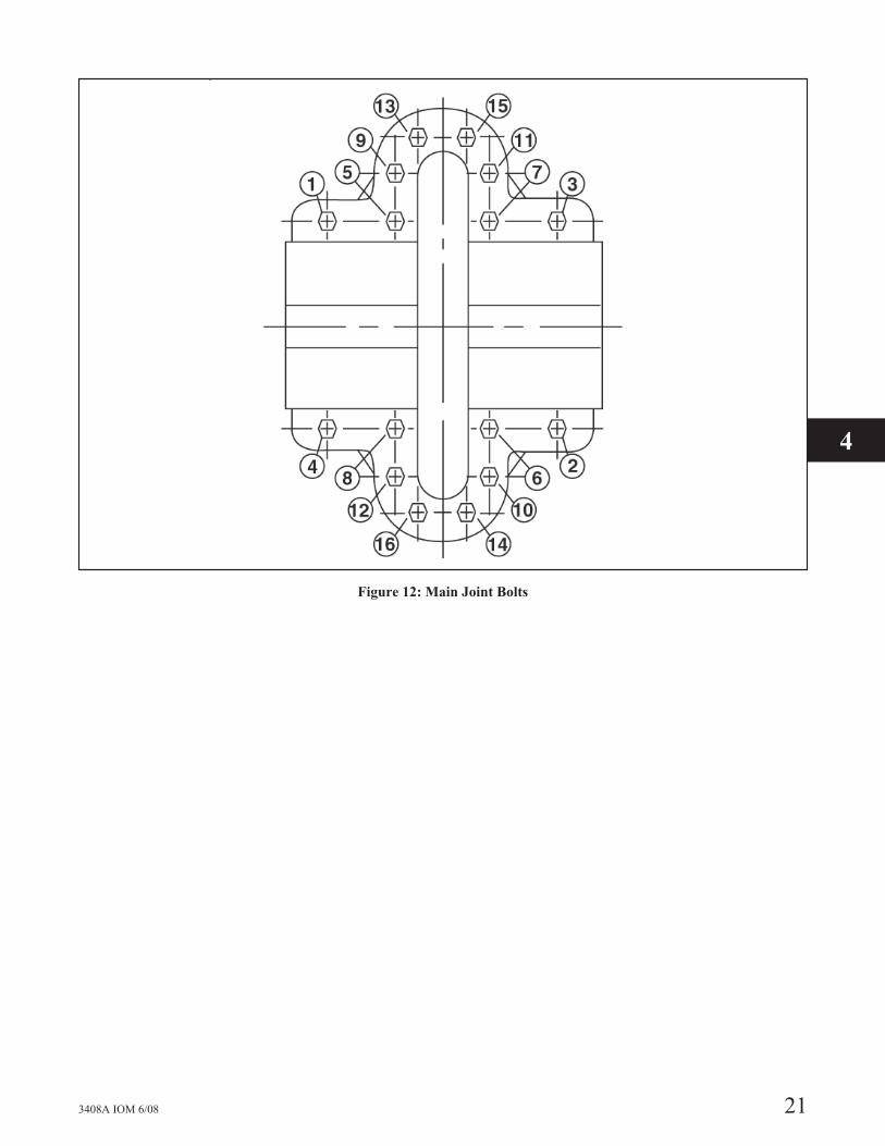
Figure 12: Main Joint Bolts
3408A IOM 6/08 21
4

22 3408A IOM 6/08

PREVENTIVE MAINTENANCE
TROUBLESHOOTING
Between regular maintenance inspections, be alert for signs of motor or pump trouble. Common symptoms are listed below.Correct any trouble immediately and avoid costly repair and shutdown.
CAUSES CURES
No Liquid Delivered
1. Lack of prime Fill pump and suction pipe completely with liquid.
2. Loss of primeCheck for leaks in suction pipe joints and fittings; vent casing to removeaccumulated air.
3. Suction lift too high
If no obstruction at inlet, check for pipe friction losses. However, staticlift may be too great. Measure with mercury column or vacuum gaugewhile pump operates. If static lift is too high, liquid to be pumped must beraised or pump lowered.
4. Discharge head too highCheck pipe friction losses. Large piping may correct condition. Checkthat valves are wide open.
5. Speed too lowCheck whether motor is directly across-the-line and receiving full voltage.Or frequency may be too low; motor may have an open phase.
6. Wrong direction of rotation Check motor rotation with directional arrow on pump casing.
7. Impeller completely plugged Dismantle pump and clean impeller. Not Enough Liquid Delivered
Not Enough Liquid Delivered
8. Air leaks in suction piping
If liquid pumped is water or other non-explosive, and explosive gas ordust is not present, test flanges for leakage with flame or match, or byplugging inlet and putting line under pressure. A gauge will indicate aleak with a drop of pressure.
9. Speed too low See item 5.
10. Discharge head too high See item 4.
11. Suction lift too high See item 3.
12. Impeller partially plugged See item 7.
13. Cavitation; insufficient NPSH (dependingon installation)
a. Increase positive suction head on pump by lowering pump.b. Sub-coolsuction piping at inlet to lower entering liquid temperature.c.Pressurization suction vessel.
14. Defective impellerInspect impeller, bearings and shaft. Replace if damaged or vane sectionsbadly eroded.
15. Foot valve too small or partially obstructedArea through ports of valve should be at least as large as area of suctionpipe – preferably 1-1/2 times. If strainer is used, net clear area should be 3to 4 times area of suction pipe.
16. Suction inlet not immersed deeply enoughIf inlet cannot be lowered, or if eddies through which air is sucked persistwhen it is lowered, chain a board to suction pipe. It will be drawn intoeddies, smothering the vortex
17. Wrong direction of rotationSymptoms are an overloaded drive and about 1/3 rated capacity frompump. Compare the rotation of the motor with the directional arrow on thepump casing.
3408A IOM 6/08 23
4

CAUSES CURES
18. Too small impeller diameter (probablecause if none of the above)
Check with the factory to see if a larger impeller can be used; otherwise,cut the pipe losses or increase the speed, or both as needed. Be careful notto overload the driver.
19. Air leaks in suction piping See item 8.
Not Enough Pressure
20. Mechanical defects See items 14 and 15.
21. Obstruction in liquid passagesDismantle pump and inspect passages of impeller and casing. Removeobstruction.
22. Air or gases in liquid (Test in laboratory,reducing pressure on liquid to pressure insuction line. Watch for bubble formation.)
May be possible to overrate pump to the point where it will provideadequate pressure despite condition. Better to provide gas separationchamber on suction line near pump, and periodically exhaust accumulatedgas. See item 13.
23. Too small impeller diameter (Probablecause if none above)
See item 18.
24. Speed too low See item 5.
Pump Operates For Short Time, Then Stops
25. Incomplete primingFree pump, piping and valves of all air. If high points in suction lineprevent this, they need correcting. See the section entitled Suction Piping.
26. Suction lift too high See item 3.
27. Air leaks in suction piping See item 8.
28. Air or gases in liquid See item 22.
Pump Takes Too Much Power
29. Head lower than rating; thereby pumpingtoo much liquid
Machine impeller’s OD to size advised by factory.
30. Cavitation See item 13.
31. Mechanical defects. See items 14 and 15.
32. Suction inlet not immersed enough See item 16.
33. Liquid heavier (in either viscosity orspecific gravity) than allowed for
Use larger driver. Consult factory for recommended size. Test liquid forviscosity and specific gravity.
34. Wrong direction of rotation See item 6.
35. Casing distorted by excessive strains fromsuction or discharge piping
Check alignment. Examine pump for friction between impeller andcasing. Replace damaged parts.
36. Shaft bent due to damage – throughshipment, operation, or overhaul
Check deflection of rotor by turning on bearing journals. Total indicatorrun-out should not exceed 0.002” on shaft and 0.004” on impeller wearingsurface.
37. Mechanical failure of critical pump partsCheck bearings and impeller for damage. Any irregularity in these partswill cause a drag on shaft.
38. Misalignment Realign pump and driver.
39. Speed may be too high (brake hp of pumpvaries as the cube of the speed; therefore, anyincrease in speed means considerable increasein power demand.)
Check voltage on motor.
40. Electrical defectsThe voltage and frequency of the electrical current may be lower than thatfor which the motor was built; or there may be defects in motor. Themotor may not be ventilated properly due to a poor location.
41. Mechanical defects in turbine, engine orother type of drive exclusive of motor
If trouble cannot be located, consult factory.
24 3408A IOM 6/08

MAINTENANCE
GENERAL MAINTENANCEOperating conditions vary so widely that to recommend oneschedule of preventative maintenance for all centrifugalpumps is not possible. Yet some sort of regular inspectionmust be planned and followed. We suggest a permanentrecord be kept of the periodic inspections and maintenanceperformed on your pump. This recognition of maintenanceprocedure will keep your pump in good working condition,and prevent costly breakdown.
One of the best rules to follow in the proper maintenance ofyour centrifugal pump is to keep a record of actualoperating hours. Then, after a predetermined period ofoperation has elapsed, the pump should be given athorough inspection. The length of this operating periodwill vary with different applications, and can only bedetermined from experience. New equipment, however,should be examined after a relatively short period ofoperation. The next inspection period can be lengthenedsomewhat. This system can be followed until a maximumperiod of operation is reached which should be consideredthe operating schedule between inspections.
MAINTENANCE OF PUMP DUE TOFLOOD DAMAGEThe servicing of centrifugal pumps after a floodedcondition is a comparatively simple matter under normalconditions.
Bearings are a primary concern on pumping units. First,dismantle the bearings; clean and inspect them for anyrusted or badly worn surfaces. If bearings are free from rustand wear, reassemble and relubricate them with one of therecommended pump lubricants. Depending on the length oftime the pump has remained in the flooded area, it isunlikely that bearing replacement is necessary; however, inthe event that rust or worn surfaces appear, it may benecessary to replace the bearings.
Next, inspect the stuffing box, and clean out any foreignmatter that might clog the box. Mechanical seals should becleaned and thoroughly flushed.
Couplings should be dismantled and thoroughly cleaned.
Any pump that is properly sealed at all joints and connectedto both the suction and discharge should exclude outsideliquid. Therefore, it should not be necessary to go beyondthe bearings, stuffing box, and coupling when servicing thepump.
BEARING LUBRICATION – GREASEGrease lubricated ball bearings are packed with grease atthe factory and ordinarily will require no attention beforestarting, provided the pump has been stored in a clean, dry
place prior to its first operation. The bearings should bewatched the first hour or so after the pump has been startedto see that they are operating properly.
The importance of proper lubrication cannot be overemphasized. It is difficult to say how often a bearingshould be greased, since that depends on the conditions ofoperation. It is well advised to add one ounce of grease atregular intervals, but it is equally important to avoid addingtoo much grease. For average operating conditions, it isrecommended that 1 oz. of grease be added at intervals ofthree to six months, and only clean grease be used. It isalways best if unit can be stopped while grease is added toavoid overloading.
The grease relief plug should be removed from theoutboard bearing housing before adding new grease to thebearing. The plug should then be left out until the pump isrun for a minimum of 2 hours and the system has reachedits normal operating temperature.
NOTE: Excess grease is the most common cause ofoverheating.
A lithium-based NLGI-2 grade grease should be used forlubricating bearings where the ambient temperature isabove -20°F. Grease lubricated bearings are packed at thefactory with Shell Alvania No. 2. Other recommendedgreases are Texaco Multifak No. 2 and Mobilux No. 2grease.
Greases made from animal or vegetable oils are notrecommended due to the danger of deterioration andforming of acid. Do not use graphite.
The maximum desirable operating temperature for ballbearings is 180°F. Should the temperature of the bearingframe rise above 180°F, the pump should be shut down todetermine the cause.
MECHANICAL SEALS1. Mechanical seals are precision products and should be
treated with care. Use special care when handlingseals. Clean parts are essential to prevent scratchingthe finely lapped sealing faces. Even light scratches onthese faces could result in leaky seals.
2. Normally, mechanical seals require no adjustment ormaintenance, except routine replacement of worn orbroken parts.
3. A mechanical seal which has been used should not beput back into service until the sealing faces have beenreplaced or relapped. (Relapping is generallyeconomical only in seals two inches in size andabove.)
3408A IOM 6/08 25
4

CLEANING WITHOUTDISMANTLING PUMPA short section of pipe, so designed that it can be readilydropped out of the line, can be installed adjacent to thesuction flange. With this arrangement, any matter cloggingthe impeller is accessible by removing the pipe section.
If the pump cannot be freed of clogging after the abovemethods have been tried, dismantle the unit as previouslydescribed to locate the trouble.
SERVICE
Figure 13: Mechanical View
26 3408A IOM 6/08

REPLACING MECHANICAL SEALSAND BEARINGS
(without removing the upper half of the casing)
NOTE: In order to replace the mechanical seal andbearing housing on the coupler end, you must use aspacer type coupler.
�! WARNINGUnexpected Startup Hazard
Disconnect and lockout power before servicing.
Failure to follow these instructions could result in seri-ous personal injury or death, or property damage.
�! CAUTION
Extreme Temperature Hazard
Allow pump temperatures to reach acceptable levelsbefore proceeding. Open the drain valve. Do notproceed until liquid stops coming out of the drainvalve. If liquid does not stop flowing from the drainvalve, isolation valves are not sealing and should berepaired before proceeding. After liquid stops flowingfrom drain valve, leave the valve open and continue.Remove the drain plug located on the bottom of thepump housing. Do not reinstall the plug or closethedrain valve until reassembly is completed.
Failure to follow these instructions could result inmoderate personal injury or property damage.
1. Close valves on suction and discharge sides of pump.If no valves have been installed, it will be necessary todrain the system.
2. Remove the coupler guard. For spacer coupler, loosenthe capscrews which secure the coupler flanges to thecoupler hubs. Remove the coupler flanges and sleeveby compressing the flanges and pulling out frombeneath the hubs or by loosening the Allen set screwsand sliding the hubs back on the shafts. Remove thecoupler hubs from the pump shaft. For non-spacercouplers, loosen set screws and slide flanges back onshafts and remove rubber element.
3. Remove the capscrews from each of the bearinghousings and remove the bearing housings by placingtwo 2.0" long full-threaded capscrews or Allen setscrews in the jackscrew holes provided.
4. Bend back the lockwasher tab and remove both thelockwasher and locknut from the outboard end of theshaft (the opposite side of the coupling).
5. Remove the socket-head capscrews holding the glandplates to the stuffing boxes.
6. Insert threaded rods into the tapped holes in the glandplate and install a fixture on the threaded rods to use apuller. See Figure 14 for Dimensions of UniversalFixture (PN: AC2394). Using the puller, tighten the
bolt in the center of the fixture to remove the bearingand gland plate from the shaft. See Figures 15 and 16.
�! CAUTION
Pump Damage Hazard
Failure to remove the socket-head capscrews beforetrying to pull the bearings off could cause damage tothe pump.
Failure to follow these instructions could result inmoderate personal injury or property damage.
Figure 14: Dimensions for Universal Fixture
(PN: AC2394)
7. Remove the inboard bearing and gland plate in thesame manner.
NOTE: The locknut and lockwasher are not used onthe inboard bearing.
�! CAUTION
Do not reuse the ball bearings
Figure 15: Removing bearing and gland plate
using universal fixture
3408A IOM 6/08 27
4
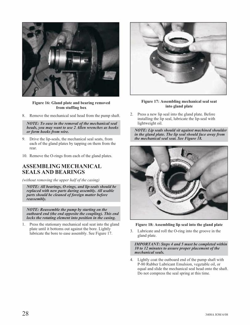
Figure 16: Gland plate and bearing removed
from stuffing box
8. Remove the mechanical seal head from the pump shaft.
NOTE: To ease in the removal of the mechanical sealheads, you may want to use 2 Allen wrenches as hooksor form hooks from wire.
9. Drive the lip-seals, the mechanical seal seats, fromeach of the gland plates by tapping on them from therear.
10. Remove the O-rings from each of the gland plates.
ASSEMBLING MECHANICALSEALS AND BEARINGS
(without removing the upper half of the casing)
NOTE: All bearings, O-rings, and lip-seals should bereplaced with new parts during assembly. All usableparts should be cleaned of foreign matter beforereassembly.
NOTE: Reassemble the pump by starting on theoutboard end (the end opposite the coupling). This endlocks the rotating element into position in the casing.
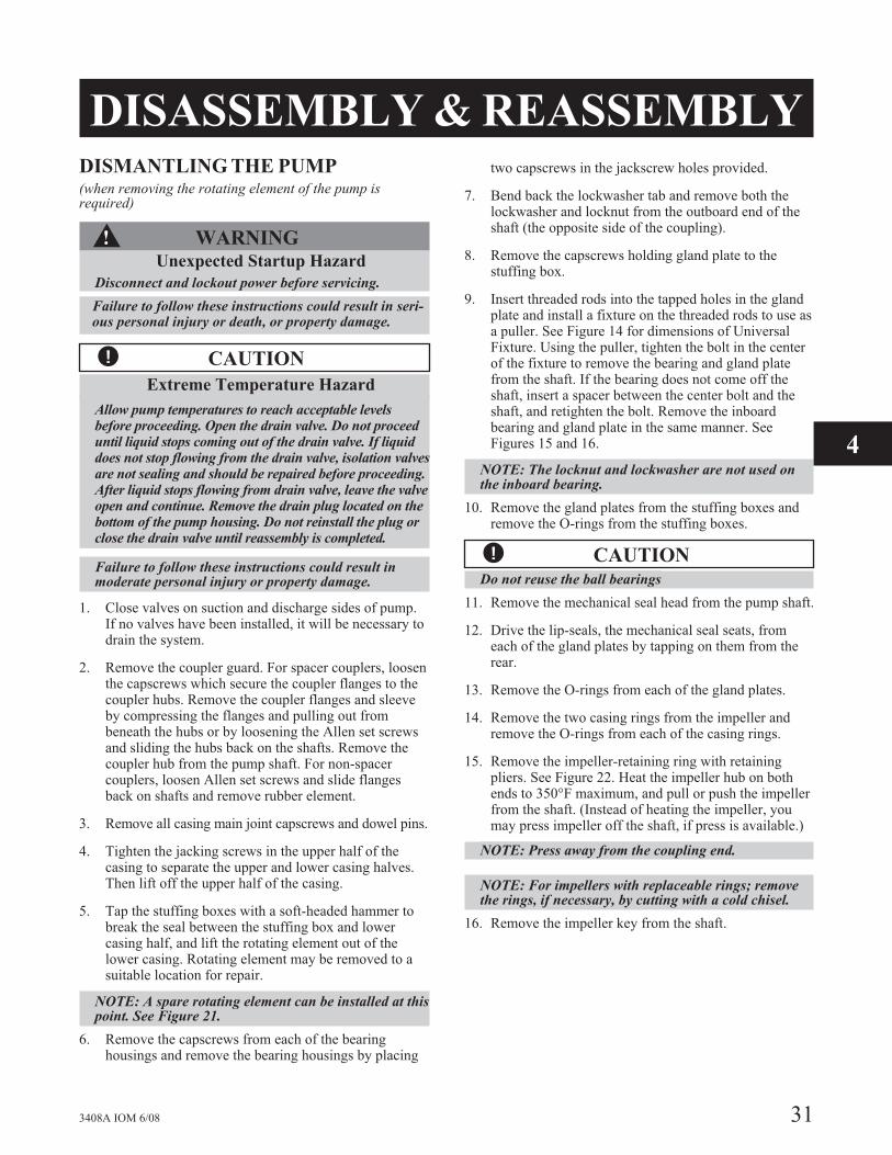
1. Press the stationary mechanical seal seat into the glandplate until it bottoms out against the bore. Lightlylubricate the bore to ease assembly. See Figure 17.
Figure 17: Assembling mechanical seal seat
into gland plate
2. Press a new lip seal into the gland plate. Beforeinstalling the lip seal, lubricate the lip-seal withlightweight oil.
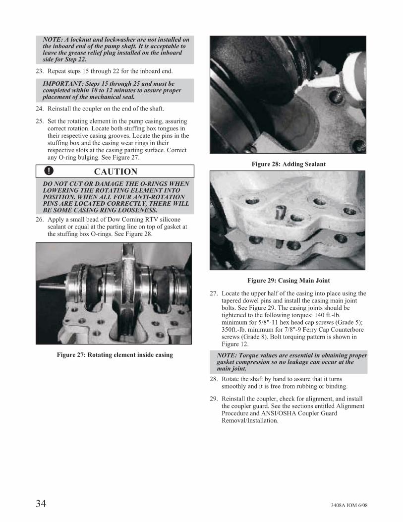
NOTE: Lip seals should sit against machined shoulderin the gland plate. The lip seal should face away fromthe mechanical seal seat. See Figure 18.
Figure 18: Assembling lip seal into the gland plate
3. Lubricate and roll the O-ring into the groove in thegland plate.
IMPORTANT: Steps 4 and 5 must be completed within10 to 12 minutes to assure proper placement of themechanical seals.
4. Lightly coat the outboard end of the pump shaft withP-80 Rubber Lubricant Emulsion, vegetable oil, orequal and slide the mechanical seal head onto the shaft.Do not compress the seal spring at this time.
28 3408A IOM 6/08

�! CAUTION
Use a flashlight and make sure the mechanical sealspring is seated properly into the spring holder andaround the bellows of the mechanical seal beforecontinuing. Without properly seating the spring, theseal will fail.
5. Slide the gland plate, over the shaft, being very carefulthat the head and the seat of the mechanical seal do notget damaged. Then press the gland plate with theO-ring into the stuffing box and tighten thesocket-head capscrews.
NOTE: Because of the compression of the O-ring, itmay be difficult to press the O-ring into the stuffingbox. Use longer socket-head capscrews to start thegland plate into the stuffing box. Draw-up the boltsevenly until the gland plate is secure in the stuffingbox. To prevent the mechanical seal spring frompushing the gland plate back out of the stuffing box,remove one long socket-head capscrew at a time andreplace with a regular sockethead capscrew.
6. Heat the ball bearings using dry heat or 10% – 15%soluble oil and water, or an induction heater.
�! CAUTIONDo not exceed a temperature of 275°F
7. Fill up the lip seal cavity with approximately .50ounces of grease.
8. Using gloves, slide the heated bearing onto the shaftagainst the shaft shoulder. See Figure 19.
Figure 19: Installing Bearing
9. Install the locknut and lockwasher on the outboard endof the shaft. Make certain that the locknut is secure andbend over the tabs on the lockwasher. See Figure 20.
10. Allow the bearing to cool to room temperature. Coatthe exposed sides of the bearing with two or threeounces of recommended grease. Drive as much greaseas possible into the bearing using a putty knife orsimilar tool.
11. Remove the grease relief plug; coat the inside of thebearing housing with grease, and then slide thehousing into place over the bearing. Alternately tightenthe bearing housing capscrews so as not to “cock” thebearing housing causing bearing to bind. Leave thegrease relief plug out of the outboard housing until thepump is run for a minimum of two hours and thesystem has reached its normal operating temperature.
NOTE: A locknut and lockwasher are not installed onthe inboard end of the pump shaft. It is acceptable toleave the grease relief plug installed on the inboardside for Step 11.
12. Repeat steps 1 through 11 for the inboard.
13. Reinstall the coupler, check for alignment, and installthe coupler guard. See the sections entitled AlignmentProcedure and ANSI/OSHA Coupler GuardRemoval/Installation.
Figure 20: Installing Lockwasher and Locknut
3408A IOM 6/08 29
4

30 3408A IOM 6/08
DISASSEMBLY & REASSEMBLYDISMANTLING THE PUMP(when removing the rotating element of the pump isrequired)
�! WARNINGUnexpected Startup Hazard
Disconnect and lockout power before servicing.
Failure to follow these instructions could result in seri-ous personal injury or death, or property damage.
�! CAUTION
Extreme Temperature Hazard
Allow pump temperatures to reach acceptable levelsbefore proceeding. Open the drain valve. Do not proceeduntil liquid stops coming out of the drain valve. If liquiddoes not stop flowing from the drain valve, isolation valvesare not sealing and should be repaired before proceeding.After liquid stops flowing from drain valve, leave the valveopen and continue. Remove the drain plug located on thebottom of the pump housing. Do not reinstall the plug orclose the drain valve until reassembly is completed.
Failure to follow these instructions could result inmoderate personal injury or property damage.
1. Close valves on suction and discharge sides of pump.If no valves have been installed, it will be necessary todrain the system.
2. Remove the coupler guard. For spacer couplers, loosenthe capscrews which secure the coupler flanges to thecoupler hubs. Remove the coupler flanges and sleeveby compressing the flanges and pulling out frombeneath the hubs or by loosening the Allen set screwsand sliding the hubs back on the shafts. Remove thecoupler hub from the pump shaft. For non-spacercouplers, loosen Allen set screws and slide flangesback on shafts and remove rubber element.
3. Remove all casing main joint capscrews and dowel pins.
4. Tighten the jacking screws in the upper half of thecasing to separate the upper and lower casing halves.Then lift off the upper half of the casing.
5. Tap the stuffing boxes with a soft-headed hammer tobreak the seal between the stuffing box and lowercasing half, and lift the rotating element out of thelower casing. Rotating element may be removed to asuitable location for repair.
NOTE: A spare rotating element can be installed at thispoint. See Figure 21.
6. Remove the capscrews from each of the bearinghousings and remove the bearing housings by placing
two capscrews in the jackscrew holes provided.
7. Bend back the lockwasher tab and remove both thelockwasher and locknut from the outboard end of theshaft (the opposite side of the coupling).
8. Remove the capscrews holding gland plate to thestuffing box.
9. Insert threaded rods into the tapped holes in the glandplate and install a fixture on the threaded rods to use asa puller. See Figure 14 for dimensions of UniversalFixture. Using the puller, tighten the bolt in the centerof the fixture to remove the bearing and gland platefrom the shaft. If the bearing does not come off theshaft, insert a spacer between the center bolt and theshaft, and retighten the bolt. Remove the inboardbearing and gland plate in the same manner. SeeFigures 15 and 16.
NOTE: The locknut and lockwasher are not used onthe inboard bearing.
10. Remove the gland plates from the stuffing boxes andremove the O-rings from the stuffing boxes.
�! CAUTIONDo not reuse the ball bearings
11. Remove the mechanical seal head from the pump shaft.
12. Drive the lip-seals, the mechanical seal seats, fromeach of the gland plates by tapping on them from therear.
13. Remove the O-rings from each of the gland plates.
14. Remove the two casing rings from the impeller andremove the O-rings from each of the casing rings.
15. Remove the impeller-retaining ring with retainingpliers. See Figure 22. Heat the impeller hub on bothends to 350°F maximum, and pull or push the impellerfrom the shaft. (Instead of heating the impeller, youmay press impeller off the shaft, if press is available.)
NOTE: Press away from the coupling end.
NOTE: For impellers with replaceable rings; removethe rings, if necessary, by cutting with a cold chisel.
16. Remove the impeller key from the shaft.
3408A IOM 6/08 31
4

Figure 21: Rotating Element
Figure 22: Removing Impeller Retaining Ring
Figure 23: Trimming Casing Gasket
REASSEMBLING THE PUMP(when removing the rotating element of the pump isrequired)
NOTE: All bearings, O-rings, lip-seals, mechanicalseals, gaskets, impeller rings, and casing rings shouldbe replaced with the new parts during assembly. Allreusable parts should be cleaned of all foreign matterbefore reassembling. The main casing joint gasket canbe made using the upper and lower half as a template.Lay the gasket material on the casing joint. Trim thegasket by lightly tapping with a ball peen hammer sothat it is flush with the inside edges of the casing. SeeFigure 23. Do not hit casing edge with hammer hardenough to round edge.
NOTE: Precut-casing gaskets can be ordered tominimize the amount of trimming.
1. Before assembling the rotating element prepare thecasing and install the casing gaskets to the parting line.
2. Clean the gasket surfaces of the casing. Apply Scotch3M-77 spray adhesive or equivalent to the lower halfof the casing.
3. Within one minute of spraying, set the untrimmedgaskets in place on the lower half of the casing, alignthe holes in the gaskets with the holes in the casing,and press the gaskets firmly against the lower half ofthe casing face in the area coated by the adhesive.
4. Trim the gaskets flush with the lower casing bores. SeeFigure 23.
�! CAUTION
Machined-casing bores must remain sharp at thecasing parting line. Gaskets must be flush with thebore in order to contact O-rings. Leakage can resultaround the stuffing box O-ring if this step is notproperly followed.
5. Assemble the impeller key in the shaft key slot.
NOTE: For impeller with replaceable rings, heat eachnew ring (approximately 300°F-400°F for bronze) andslide onto the impeller. Using gloves, hold rings againstthe impeller shoulder until cool.
6. Check the impeller and casing to determine the correctrelationship. Heat the impeller evenly to 300°Fmaximum to expand the bore. Impeller may be pressedonto the shaft instead of heating if a suitable press isavailable. See Figure 24.
7. Using gloves, from the outboard end, slide the impelleron the shaft against the shaft shoulder, and install theretaining ring.
8. Lubricate and roll an O-ring into the groove in each ofthe casing rings. Then slide the casing rings over theimpeller.
9. Thoroughly clean the gland plates and stuffing boxesto prevent dirt from entering the seal during startup.
32 3408A IOM 6/08

Press the stationary mechanical seal seats into both of thegland plates. Lightly lubricate the gland plates to easeassembly. See Figure 17.
IMPORTANT: Steps 11 through 21 must be completed,on the outboard end, within 10 to 12 minutes to assureproper placement of the mechanical seals
11. Press new lip seals into the gland plates. Beforeinstalling the lip seals, lubricate the lip seals withlightweight oil.
NOTE: Lip seals should sit against the machinedshoulder in the gland plates. The lip seals should faceaway from the mechanical seal seats. See Figure 18.
12. Lubricate and roll the O-rings into the grooves in eachgland plate.
13. Press the gland plates into the stuffing boxes andsecure using the socket-head capscrews.
NOTE: Because of the compression of the O-ring, itmay be difficult to press the O-ring into the stuffingbox. Use longer socket-head capscrews to start thegland plate into the stuffing box. To prevent themechanical seal spring from pushing the gland plateback out of the stuffing box, remove one longsocket-head capscrew at a time and replace with aregular socket-head capscrew.
Figure 24: Pressing Impeller on Shaft
Figure 25: Installing Mechanical Seal Head
Figure 26: Installing Stuffing Box
14 Lubricate and roll the O-rings into the groove in eachstuffing box.
NOTE: At this point reassemble the rotating elementby starting on the outboard end first (the end oppositethe coupling) as this end locates the settings of themechanical seal.
15. Lightly coat the outboard end of the pump shaft withP-80 Rubber Lubricant Emulsion, vegetable oil, orequal and slide the mechanical seal head onto the shaft.See Figure 25.
16. Slide the stuffing box, with the gland plate, fully onthe shaft, being very careful that the head and seat ofthe mechanical seal do not get damaged.
NOTE: Compress the seal spring only as far asrequired to install the bearings. See Figure 26.
17. Fill lip seal cavity with approximately .50 ounces ofgrease.
18. Heat the ball bearings using dry heat to 10% – 15%soluble oil and water, or an induction heater.
�! CAUTIONDo not exceed a temperature of 275°F..
19. Using gloves, slide the heated bearing onto the shaftagainst the shaft shoulder. See Figure 19.
20. Install the locknut and lockwasher on the outboard endof the shaft. Make certain that the locknut is secure andbend over the tabs on the lockwasher. See Figure 20.
21. Allow the bearing to cool to room temperature. Coat theexposed sides of the bearing with two or three ounces ofrecommended grease. Drive as much grease as possibleinto the bearing using a putty knife or similar tool.
22. Remove the grease relief plug; coat the inside of thebearing housing with grease and then slide the housinginto place over the bearing. Attach the bearing housingto the stuffing box with the capscrews. Leave thegrease relief plug out of the outboard housing until thepump is run for a minimum of two hours and thesystem has reached its normal operating temperature.
3408A IOM 6/08 33
4
NOTE: A locknut and lockwasher are not installed onthe inboard end of the pump shaft. It is acceptable toleave the grease relief plug installed on the inboardside for Step 22.
23. Repeat steps 15 through 22 for the inboard end.
IMPORTANT: Steps 15 through 25 and must becompleted within 10 to 12 minutes to assure properplacement of the mechanical seal.
24. Reinstall the coupler on the end of the shaft.
25. Set the rotating element in the pump casing, assuringcorrect rotation. Locate both stuffing box tongues intheir respective casing grooves. Locate the pins in thestuffing box and the casing wear rings in theirrespective slots at the casing parting surface. Correctany O-ring bulging. See Figure 27.
�! CAUTION
DO NOT CUT OR DAMAGE THE O-RINGS WHENLOWERING THE ROTATING ELEMENT INTOPOSITION. WHEN ALL FOUR ANTI-ROTATIONPINS ARE LOCATED CORRECTLY, THERE WILLBE SOME CASING RING LOOSENESS.
26. Apply a small bead of Dow Corning RTV siliconesealant or equal at the parting line on top of gasket atthe stuffing box O-rings. See Figure 28.
Figure 27: Rotating element inside casing
Figure 28: Adding Sealant
Figure 29: Casing Main Joint
27. Locate the upper half of the casing into place using thetapered dowel pins and install the casing main jointbolts. See Figure 29. The casing joints should betightened to the following torques: 140 ft.-lb.minimum for 5/8"-11 hex head cap screws (Grade 5);350ft.-lb. minimum for 7/8"-9 Ferry Cap Counterborescrews (Grade 8). Bolt torquing pattern is shown inFigure 12.
NOTE: Torque values are essential in obtaining propergasket compression so no leakage can occur at themain joint.
28. Rotate the shaft by hand to assure that it turnssmoothly and it is free from rubbing or binding.
29. Reinstall the coupler, check for alignment, and installthe coupler guard. See the sections entitled AlignmentProcedure and ANSI/OSHA Coupler GuardRemoval/Installation.
34 3408A IOM 6/08
SPARE AND REPAIR PARTSORDERING PARTSThe pumps covered by this manual have been designed andbuilt with certain replaceable wearing parts. Therecommended inventory of spare parts depends upon theinstallation and the importance of continued operation.
For critical service requiring a minimum of down-time, acomplete or quick-change rotating element isrecommended.
For normal service, with repairs to be made in the field, thefollowing parts are recommended for stock.
• 1 set of bearings
• 1 set of wearing rings
• 1 set of casing gaskets, O-rings and lip seals
• 2 mechanical seals (complete)
Parts should be ordered as far in advance of their use aspossible since circumstances beyond the control of thecompany may reduce existing stock. Not all parts arestocked and must be manufactured for each order.
To facilitate rapid handling of your order for spare parts, besure to include the following information:
1. Serial number of the pump. (See the pump nameplate.)
2. Name of the part.
3. Quantity of each part.
4. Material desired. (Parts will be furnished in originalmaterials unless specified as a material change. Allmaterial substitutions should be discussed with thefactory.)
DEALER SERVICINGIf trouble occurs that cannot be rectified, contact your localGoulds Pumps representative. The representative will needthe following information in order to provide assistance:
1. Complete nameplate data of the pump and motor.
2. Suction and discharge pipe pressure gauge readings.
3. Ampere draw of the motor.
4. A sketch of the pumping hook-up and piping.
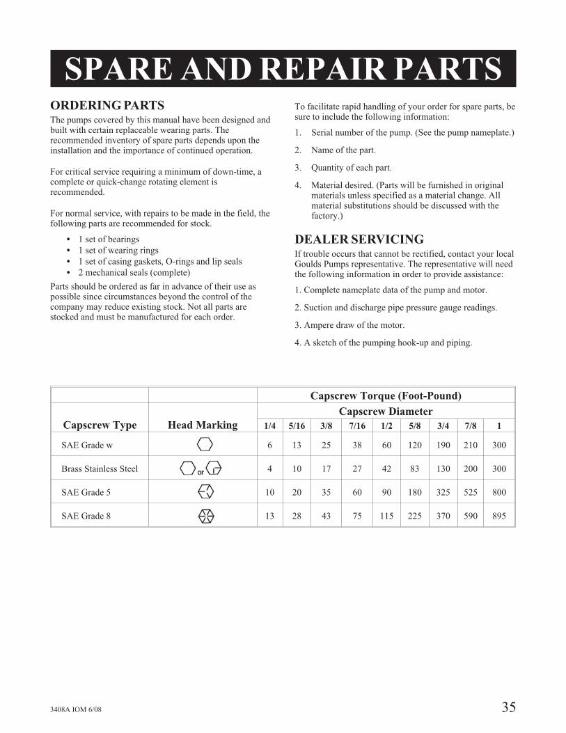
3408A IOM 6/08 35
Capscrew Torque (Foot-Pound)
Capscrew Type Head Marking
Capscrew Diameter
1/4 5/16 3/8 7/16 1/2 5/8 3/4 7/8 1
SAE Grade w 6 13 25 38 60 120 190 210 300
Brass Stainless Steel 4 10 17 27 42 83 130 200 300
SAE Grade 5 10 20 35 60 90 180 325 525 800
SAE Grade 8 13 28 43 75 115 225 370 590 895

HOW TO ORDER
When ordering parts call
1-800-446-8537
or your local Goulds Representative
EMERGENCY SERVICE
Emergency parts service is available
24 hours/day, 365 days/year . . .
Call 1-800-446-8537
Form I3408A 6/08 © copyright 2008 Goulds Pumps, Incorporated
subsidiary of ITT Corporation
Visit our website at www.gouldspumps.com