Macro Assembler and Utilities for 8051 and Variantsjel/course/587/datasheets/A51.pdf · Macro...
415
Macro Assembler and Utilities for 8051 and Variants Macro Assembler, Linker/Locator, Library Manager, Object Hex-Converter for 8051, extended 8051 and 251 Microcontrollers User’s Guide 07.2000
Transcript of Macro Assembler and Utilities for 8051 and Variantsjel/course/587/datasheets/A51.pdf · Macro...

Macro Assemblerand Utilities for
8051 and Variants
Macro Assembler, Linker/Locator, Library Manager, Object Hex-Converter
for 8051, extended 8051 and 251 Microcontrollers
User’s Guide 07.2000

2 Keil Software
Information in this document is subject to change without notice and does not represent a commitment on the part of the manufacturer. The software described in this document is furnished under license agreement or nondisclosure agreement and may be used or copied only in accordance with the terms of the agreement. It is against the law to copy the software on any medium except as specifically allowed in the license or nondisclosure agreement. The purchaser may make one copy of the software for backup purposes. No part of this manual may be reproduced or transmitted in any form or by any means, electronic or mechanical, including photocopying, recording, or information storage and retrieval systems, for any purpose other than for the purchaser’s personal use, without written permission. © Copyright 1988 -2000 Keil Elektronik GmbH., and Keil Software, Inc. All rights reserved.
Keil C51™, Keil C251™ and µVision2™ are trademarks of Keil Elektronik GmbH. Microsoft® and Windows™ are trademarks or registered trademarks of Microsoft Corporation. Intel®, MCS® 51, MCS® 251, ASM–51®, and PL/M–51® are registered trademarks of Intel Corporation.
Every effort was made to ensure accuracy in this manual and to give appropriate credit to persons, companies, and trademarks referenced herein.
Macro Assembler and Utilities for 8051 and Variants 3
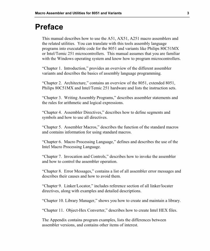
Preface This manual describes how to use the A51, AX51, A251 macro assemblers and the related utilities. You can translate with this tools assembly language programs into executable code for the 8051 and variants like Philips 80C51MX or Intel/Temic 251 microcontrollers. This manual assumes that you are familiar with the Windows operating system and know how to program microcontrollers.
“Chapter 1. Introduction,” provides an overview of the different assembler variants and describes the basics of assembly language programming.
“Chapter 2. Architecture,” contains an overview of the 8051, extended 8051, Philips 80C51MX and Intel/Temic 251 hardware and lists the instruction sets.
“Chapter 3. Writing Assembly Programs,” describes assembler statements and the rules for arithmetic and logical expressions.
“Chapter 4. Assembler Directives,” describes how to define segments and symbols and how to use all directives.
“Chapter 5. Assembler Macros,” describes the function of the standard macros and contains information for using standard macros.
“Chapter 6. Macro Processing Language,” defines and describes the use of the Intel Macro Processing Language.
“Chapter 7. Invocation and Controls,” describes how to invoke the assembler and how to control the assembler operation.
“Chapter 8. Error Messages,” contains a list of all assembler error messages and describes their causes and how to avoid them.
“Chapter 9. Linker/Locator,” includes reference section of all linker/locater directives, along with examples and detailed descriptions.
“Chapter 10. Library Manager,” shows you how to create and maintain a library.
“Chapter 11. Object-Hex Converter,” describes how to create Intel HEX files.
The Appendix contains program examples, lists the differences between assembler versions, and contains other items of interest.
4 Preface
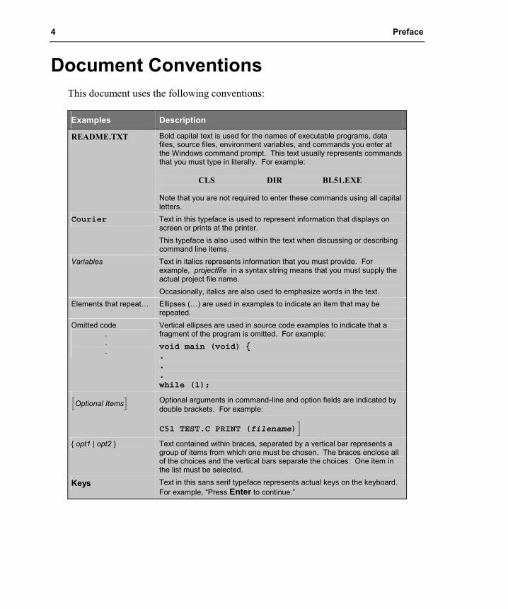
Document Conventions This document uses the following conventions:
Examples Description
README.TXT Bold capital text is used for the names of executable programs, data files, source files, environment variables, and commands you enter at the Windows command prompt. This text usually represents commands that you must type in literally. For example: CLS DIR BL51.EXE Note that you are not required to enter these commands using all capital letters.
Courier Text in this typeface is used to represent information that displays on screen or prints at the printer. This typeface is also used within the text when discussing or describing command line items.
Variables Text in italics represents information that you must provide. For example, projectfile in a syntax string means that you must supply the actual project file name. Occasionally, italics are also used to emphasize words in the text.
Elements that repeat… Ellipses (…) are used in examples to indicate an item that may be repeated.
Omitted code . . .
Vertical ellipses are used in source code examples to indicate that a fragment of the program is omitted. For example: void main (void) {...while (1);
�Optional Items� Optional arguments in command-line and option fields are indicated by double brackets. For example:
C51 TEST.C PRINT (filename)�
{ opt1 | opt2 } Text contained within braces, separated by a vertical bar represents a group of items from which one must be chosen. The braces enclose all of the choices and the vertical bars separate the choices. One item in the list must be selected.
Keys Text in this sans serif typeface represents actual keys on the keyboard. For example, “Press Enter to continue.”

Macro Assembler and Utilities for 8051 and Variants 5
Directives or options marked with shading are available in AX51 and A251 only
Contents Chapter 1. Introduction....................................................................................15
How to Develop A Program ....................................................................................... 16 What is an Assembler?.......................................................................................... 16 Modular Programming .......................................................................................... 17
Modular Program Development Process .................................................................... 19 Segments, Modules, and Programs ....................................................................... 19 Translate and Link Process ................................................................................... 20 Filename Extensions ............................................................................................. 22
Program Template File ............................................................................................... 23 Chapter 2. Architecture Overview ..................................................................27
Memory Classes and Memory Layout ........................................................................ 27 Classic 8051 .......................................................................................................... 28
Classic 8051 Memory Layout.......................................................................... 29 Extended 8051 Variants ........................................................................................ 30
Extended 8051 Memory Layout ...................................................................... 31 Philips 80C51MX ................................................................................................. 32
80C51MX Memory Layout ............................................................................. 33 Intel/Temic 251..................................................................................................... 34
251 Memory Layout ........................................................................................ 35 CPU Registers............................................................................................................. 36
CPU Registers of the 8051 Variants ..................................................................... 36 CPU Registers of the Intel/Temic 251 .................................................................. 37 Program Status Word (PSW) ................................................................................ 39
Instruction Sets ........................................................................................................... 40 Opcode Map ............................................................................................................... 63
8051 Instructions................................................................................................... 64 Additional 251 Instructions................................................................................... 65 Additional 80C51MX Instructions via Prefix A5.................................................. 66
Chapter 3. Writing Assembly Programs ........................................................67 Assembly Statements .................................................................................................. 67
Directives .............................................................................................................. 68 Controls................................................................................................................. 68 Instructions............................................................................................................ 68
Comments ................................................................................................................... 69 Symbols ...................................................................................................................... 70
Symbol Names ...................................................................................................... 70 Labels.......................................................................................................................... 71 Operands..................................................................................................................... 72
Special Assembler Symbols .................................................................................. 73 Immediate Data ..................................................................................................... 74 Memory Access..................................................................................................... 74

6 Chapter 1. Introduction
Directives or options marked with shading are available in AX51 and A251 only
1
DATA..............................................................................................................75 BIT ..................................................................................................................75 EBIT (only on Intel/Temic 251) ......................................................................76 IDATA.............................................................................................................76 EDATA (Intel/Temic 251 and Philips 80C51MX only)..................................77 XDATA ...........................................................................................................77 CODE and CONST .........................................................................................78 HDATA and HCONST....................................................................................79
Program Addresses................................................................................................80 Expressions and Operators..........................................................................................82
Numbers ................................................................................................................82 Colon Notation for Numbers (A251 only) ......................................................83
Characters..............................................................................................................84 Character Strings ...................................................................................................84 Location Counter...................................................................................................85 Operators ...............................................................................................................85
Arithmetic Operators .......................................................................................85 Binary Operators..............................................................................................86 Relational Operators ........................................................................................87 Class Operators................................................................................................88 Type Operators ................................................................................................88 Miscellaneous Operators .................................................................................89 Operator Precedence........................................................................................90
Expressions............................................................................................................90 Expression Classes...........................................................................................91 Relocatable Expressions ..................................................................................92 Simple Relocatable Expressions ......................................................................92 Extended Relocatable Expressions ..................................................................93 Examples with Expressions .............................................................................94
Chapter 4. Assembler Directives .....................................................................95 Introduction.................................................................................................................95 Segment Directives .....................................................................................................98
Location Counter...................................................................................................98 Generic Segments..................................................................................................98 Stack Segment .....................................................................................................100 Absolute Segments ..............................................................................................101 Default Segment ..................................................................................................101 SEGMENT..........................................................................................................102 RSEG...................................................................................................................105 BSEG, CSEG, DSEG, ISEG, XSEG...................................................................106
Symbol Definition.....................................................................................................108 EQU, SET ...........................................................................................................108 CODE, DATA, IDATA, XDATA.......................................................................109 esfr, sfr, sfr16, sbit...............................................................................................110 LIT (AX51 & A251 only) ..................................................................................111

Macro Assembler and Utilities for 8051 and Variants 7
Directives or options marked with shading are available in AX51 and A251 only
Memory Initialization ............................................................................................... 113 DB....................................................................................................................... 113 DW...................................................................................................................... 113 DD (AX51 & A251 only) ................................................................................ 114
Reserving Memory.................................................................................................... 115 DBIT ................................................................................................................... 115 DS ....................................................................................................................... 116 DSB (AX51 & A251 only) .............................................................................. 117 DSW (AX51 & A251 only) ............................................................................. 118 DSD (AX51 & A251 only) .............................................................................. 119
Procedure Declaration (AX51 & A251 only) .......................................................... 120 PROC / ENDP (AX51 & A251 only) .............................................................. 120 LABEL (AX51 and A251 only)....................................................................... 121
Program Linkage....................................................................................................... 122 PUBLIC .............................................................................................................. 122 EXTRN / EXTERN ............................................................................................ 123 NAME................................................................................................................. 124
Address Control ........................................................................................................ 125 ORG.................................................................................................................... 125 EVEN (AX51 and A251 only) ......................................................................... 126 USING ................................................................................................................ 126
Other Directives........................................................................................................ 128 END .................................................................................................................... 128 _ _ERROR_ _ ..................................................................................................... 128
Chapter 5. Assembler Macros........................................................................129 Standard Macro Directives ....................................................................................... 130 Defining a Macro ...................................................................................................... 131
Parameters........................................................................................................... 132 Labels.................................................................................................................. 132 Repeating Blocks ................................................................................................ 134 REPT................................................................................................................... 134 IRP ...................................................................................................................... 134 IRPC.................................................................................................................... 135 Nested Definitions............................................................................................... 136 Nested Repeating Blocks .................................................................................... 136 Recursive Macros................................................................................................ 137
Operators .................................................................................................................. 138 NUL Operator ..................................................................................................... 139 & Operator .......................................................................................................... 140 < and > Operators ............................................................................................... 141 % Operator .......................................................................................................... 142 ;; Operator ........................................................................................................... 143 ! Operator ............................................................................................................ 143
Invoking a Macro...................................................................................................... 144 C Macros................................................................................................................... 145

8 Chapter 1. Introduction
Directives or options marked with shading are available in AX51 and A251 only
1
C Macro Preprocessor Directives........................................................................145 Stringize Operator ...............................................................................................146 Token-pasting Operator.......................................................................................147 Predefined C Macro Constants............................................................................148 Examples with C Macros.....................................................................................148 C Preprocessor Side Effects ................................................................................149
Chapter 6. Macro Processing Language .......................................................151 Overview...................................................................................................................151 Creating and Calling MPL Macros ...........................................................................151 Creating Parameterless Macros.................................................................................152 MPL Macros with Parameters...................................................................................153 Local Symbols List....................................................................................................156 Macro Processor Language Functions ......................................................................157
Comment Function ..............................................................................................157 Escape Function ..................................................................................................158 Bracket Function .................................................................................................158 METACHAR Function .......................................................................................159 Numbers and Expressions ...................................................................................160 Numbers ..............................................................................................................161 Character Strings .................................................................................................162 SET Function.......................................................................................................163 EVAL Function ...................................................................................................164 Logical Expressions and String Comparison.......................................................165
Conditional MPL Processing ....................................................................................166 IF Function ..........................................................................................................166 WHILE Function.................................................................................................167 REPEAT Function...............................................................................................167 EXIT Function.....................................................................................................168
String Manipulation Functions..................................................................................169 LEN Function......................................................................................................169 SUBSTR Function...............................................................................................170 MATCH Function ...............................................................................................171
Console I/O Functions...............................................................................................172 Advanced Macro Processing.....................................................................................173
Literal Delimiters ................................................................................................174 Blank Delimiters..................................................................................................175 Identifier Delimiters ............................................................................................175 Literal and Normal Mode ....................................................................................176
MACRO Errors .........................................................................................................177 Chapter 7. Invocation and Controls ..............................................................179
Environment Settings ................................................................................................179 Running Ax51 ...........................................................................................................180
ERRORLEVEL...................................................................................................181 Output Files .........................................................................................................181
Assembler Controls...................................................................................................181

Macro Assembler and Utilities for 8051 and Variants 9
Directives or options marked with shading are available in AX51 and A251 only
CASE (AX51 and A251 only)...................................................................... 184 COND / NOCOND ....................................................................................... 185 DATE ............................................................................................................ 186 DEBUG......................................................................................................... 187 EJECT ........................................................................................................... 188 ERRORPRINT.............................................................................................. 189 FIXDRK (A251 only) ................................................................................ 190 GEN / NOGEN.............................................................................................. 191 INCDIR......................................................................................................... 192 INCLUDE ..................................................................................................... 193 INTR2 (A251 only) ..................................................................................... 194 LIST / NOLIST ............................................................................................. 195 MOD51, MOD_CONT, MOD_MX51 (AX51 only) .................................. 196 MODSRC (A251 only)................................................................................ 197 MPL .............................................................................................................. 198 NOLINES...................................................................................................... 199 NOMACRO .................................................................................................. 200 NOMOD51.................................................................................................... 201 NOSYMBOLS .............................................................................................. 202 OBJECT / NOOBJECT................................................................................. 203 PAGELENGTH, PAGEWIDTH................................................................... 204 PRINT / NOPRINT....................................................................................... 205 REGISTERBANK / NOREGISTERBANK.................................................. 206 REGUSE ....................................................................................................... 207 SAVE / RESTORE........................................................................................ 208 SYMLIST / NOSYMLIST............................................................................ 209 TITLE............................................................................................................ 210 XREF............................................................................................................. 211
Controls for Conditional Assembly........................................................................... 212 Conditional Assembly Controls .......................................................................... 212
Predefined Constants (A251 only) ............................................................... 213 SET................................................................................................................ 214 RESET .......................................................................................................... 215 IF ................................................................................................................... 216 ELSEIF.......................................................................................................... 217 ELSE ............................................................................................................. 218 ENDIF........................................................................................................... 219
Chapter 8. Error Messages ............................................................................221 Fatal Errors ............................................................................................................... 221 Non–Fatal Errors ...................................................................................................... 224
Chapter 9. Linker/Locator .............................................................................237 Introduction .............................................................................................................. 237 Overview................................................................................................................... 239
Combining Program Modules ............................................................................. 239 Segment Naming Conventions ............................................................................ 240

10 Chapter 1. Introduction
Directives or options marked with shading are available in AX51 and A251 only
1
Combining Segments...........................................................................................240 Locating Segments ..............................................................................................242 Overlaying Data Memory....................................................................................242 Resolving External References............................................................................243 Absolute Address Calculation .............................................................................243 Generating an Absolute Object File ....................................................................244 Generating a Listing File .....................................................................................244 Bank Switching ...................................................................................................245 Using RTX51, RTX251, and RTX51 Tiny .........................................................246
Linking Programs......................................................................................................247 Command Line Examples....................................................................................248 Control Linker Input with µVision2 ....................................................................249 ERRORLEVEL...................................................................................................249 Output File...........................................................................................................249 Linker/Locater Controls ......................................................................................250
BL51 Controls ...............................................................................................251 LX51 and L251 Controls ...............................................................................252
Locating Programs to Physical Memory ...................................................................253 Classic 8051 ........................................................................................................253
Classic 8051 without Code Banking..............................................................253 Classic 8051 with Code Banking...................................................................254
Extended 8051 Variants ......................................................................................254 Philips 80C51MX................................................................................................255 Intel/Temic 251 ...................................................................................................256
Data Overlaying ........................................................................................................257 Program and Data Segments of Functions...........................................................258 Using the Overlay Control...................................................................................259
Disable Data Overlaying................................................................................260 Pointer to a Function as Function Argument .................................................261 Pointer to a Function in Arrays or Tables......................................................263
Tips and Tricks for Program Locating ......................................................................265 Locate Segments with Wildcards ........................................................................265 Special ROM Handling (LX51 & L251 only) .....................................................265
Segment and Class Information (LX51 & L251 only)...................................266 Use RAM for the 251 Memory Class NCONST ...........................................267
Bank Switching .........................................................................................................268 Common Code Area ............................................................................................268 Code Bank Areas.................................................................................................269
Optimum Program Structure with Bank Switching........................................269 Program Code in Bank and Common Areas ..................................................270 Segments in Bank Areas ................................................................................271
Bank Switching Configuration ............................................................................271 Configuration Examples ......................................................................................274
Control Summary ......................................................................................................280 Listing File Controls............................................................................................281
DISABLEWARNING ...................................................................................282

Macro Assembler and Utilities for 8051 and Variants 11
Directives or options marked with shading are available in AX51 and A251 only
IXREF ........................................................................................................... 283 NOCOMMENTS .......................................................................................... 284 NOLINES...................................................................................................... 285 NOMAP ........................................................................................................ 286 NOPUBLICS................................................................................................. 287 NOSYMBOLS .............................................................................................. 288 PAGELENGTH / PAGEWIDTH................................................................ 289 PRINT / NOPRINT..................................................................................... 290 PRINTCONTROLS ...................................................................................... 291 PURGE.......................................................................................................... 292 WARNINGLEVEL....................................................................................... 293 Example Listing File ..................................................................................... 294
Output File Controls............................................................................................ 296 ASSIGN ........................................................................................................ 297 IBANKING ................................................................................................... 298 NAME........................................................................................................... 299 NOAJMP....................................................................................................... 300 NODEBUGLINES, NODEBUGPUBLICS, NODEBUGSYMBOLS .......... 301 NOINDIRECTCALL .................................................................................... 302 NOJMPTAB.................................................................................................. 303 NOTYPE....................................................................................................... 304 OBJECTCONTROLS ................................................................................... 305
Segment and Memory Location Controls............................................................ 306 BANKAREA................................................................................................. 307 BANKx.......................................................................................................... 308 BIT ................................................................................................................ 309 CLASSES...................................................................................................... 311 CODE............................................................................................................ 313 DATA............................................................................................................ 314 IDATA .......................................................................................................... 315 NOSORTSIZE .............................................................................................. 316 PDATA ......................................................................................................... 317 PRECEDE..................................................................................................... 318 RAMSIZE ..................................................................................................... 319 RESERVE ..................................................................................................... 320 SEGMENTS.................................................................................................. 321 SEGSIZE....................................................................................................... 323 STACK.......................................................................................................... 324 XDATA......................................................................................................... 325
High-Level Language Controls ........................................................................... 326 NODEFAULTLIBRARY.............................................................................. 327 NOOVERLAY .............................................................................................. 328 OVERLAY.................................................................................................... 329 RECURSIONS .............................................................................................. 331 REGFILE ...................................................................................................... 332 RTX251, RTX51, RTX51TINY ................................................................... 333

12 Chapter 1. Introduction
Directives or options marked with shading are available in AX51 and A251 only
1
SPEEDOVL...................................................................................................334 Error Messages..........................................................................................................335
Warnings .............................................................................................................335 Non-Fatal Errors..................................................................................................340 Fatal Errors..........................................................................................................344 Exceptions ...........................................................................................................349
Chapter 10. Library Manager ........................................................................351 Using LIBx51............................................................................................................352
Interactive Mode .................................................................................................352 Create Library within µVision2...........................................................................352
Command Summary..................................................................................................353 Creating a Library ...............................................................................................354 Adding or Replacing Object Modules .................................................................355 Removing Object Modules..................................................................................356 Extracting Object Modules..................................................................................356 Listing Library Contents......................................................................................357
Error Messages..........................................................................................................358 Fatal Errors..........................................................................................................358 Errors...................................................................................................................359
Chapter 11. Object-Hex Converter ...............................................................361 Using OHx51 ............................................................................................................362
OHx51 Command Line Examples .......................................................................363 Creating HEX Files for Banked Applications .....................................................363 OHx51 Error Messages .......................................................................................364
Using OC51 ..............................................................................................................366 OC51 Error Messages .........................................................................................367
Intel HEX File Format ..............................................................................................368 Record Format.....................................................................................................368 Data Record.........................................................................................................369 End-of-File (EOF) Record...................................................................................369 Extended 8086 Segment Record .........................................................................369 Extended Linear Address Record ........................................................................370 Example Intel HEX File ......................................................................................370
Appendix A. Application Examples...............................................................371 ASM – Assembler Example ......................................................................................371
Using A51 and BL51...........................................................................................371 Using AX51 and LX51........................................................................................372 Using A251 and L251 .........................................................................................373
CSAMPLE – C Compiler Example...........................................................................373 Using C51 and BL51...........................................................................................373 Using C51 and LX51...........................................................................................374 Using C251 and L251..........................................................................................374
BANK_EX1 – Code Banking with C51....................................................................375 Using C51 and BL51...........................................................................................375

Macro Assembler and Utilities for 8051 and Variants 13
Directives or options marked with shading are available in AX51 and A251 only
Using C51 and LX51 .......................................................................................... 376 BANK_EX2 – Banking with Constants.................................................................... 377
Using C51 and BL51........................................................................................... 377 Using C51 and LX51 .......................................................................................... 378
BANK_EX3 – Code Banking with PL/M-51 ........................................................... 378 Using BL51......................................................................................................... 379 Using C51 and LX51 .......................................................................................... 380
Philips 80C51MX – Assembler Example ................................................................. 380 Philips 80C51MX – C Compiler Example................................................................ 380
Appendix B. Reserved Symbols .....................................................................383 Appendix C. Listing File Format...................................................................385
Assembler Listing File Format.................................................................................. 385 Listing File Heading ................................................................................................. 387 Source Listing........................................................................................................... 387 Macro / Include File / Save Stack Format................................................................. 388 Symbol Table............................................................................................................ 389 Listing File Trailer .................................................................................................... 390
Appendix D. Assembler Differences..............................................................391 Differences Between A51 and A251/AX51.............................................................. 391 Differences between A51 and ASM51...................................................................... 392 Differences between A251/AX51 & ASM51 ........................................................... 393
Glossary.............................................................................................................395 Index..................................................................................................................403


Macro Assembler and Utilities for 8051 and Variants 15
1
Chapter 1. Introduction This manual describes the macro assemblers and utilities for the classic 8051, extended 8051, and 251 microcontroller families and explains the process of developing software in assembly language for these microcontroller families.
A brief overview of the classic 8051, the extended 8051, and the 251 architectures can be found in “Chapter 2. Architecture Overview” on page 27. In this overview, the differences between the classic 8051, the extended 8051 variants and the 251 processors are described. For the most complete information about the microcontroller architecture refer to the hardware reference manual of the microcontroller derivative that your are using.
For optimum support of the different 8051 and 251 variants, Keil provides the following development tools:
Development Tools Support Microcontrollers, Description
A51 Macro Assembler BL51 Linker/Locater LIB51 Library Manager
Development Tools for classic 8051. Includes support for 32 x 64KB code banks.
AX51 Macro Assembler LX51 Extended Linker/Locater LIBX51 Library Manager
Development Tools for classic and extended 8051 versions (Philips 80C51MX, Dallas 390, ect.) Supports up to 16MB code and xdata memory.
A251 Macro Assembler L251 Linker/Locater LIB251 Library Manager
Development Tools for Intel/Temic 251.
The AX51 and A251 assemblers are supersets of the A51 assembler. This user’s guide therefore covers all development tools variants. Whenever a feature or an option is available in one specific toolchain only, it is clearly marked.
For general reference to all tool variants and microcontroller architectures the terms listed in the following table are used:
Term Refers to …
Ax51 Macro Assembler A51, AX51 and A251 Macro Assembler
Cx51 Compiler C51, CX51 and C251 ANSI C Compiler
Lx51 Linker/Locator BL51, LX51 and L251 Linker/Locator
LIBx51 Library Manager LIB51, LIBX51 and LIB251 Library Manager
OHx51 Object-Hex Converter OH51, OHX51 and OH251 Object-Hex Converter
x51 Architecture or x51 Device all classic 8051, extended 8051 and 251 device variants.

16 Chapter 1. Introduction
1
How to Develop A Program This section presents an overview of the Ax51 macro assembler, Lx51 linker/locater and how it is used.
What is an Assembler? An assembler is a software tool designed to simplify the task of writing computer programs. It translates symbolic code into executable object code. This object code may then be programmed into a microcontroller and executed. Assembly language programs translate directly into CPU instructions which instruct the processor what operations to perform. Therefore, to effectively write assembly programs, you should be familiar with both the microcomputer architecture and the assembly language.
Assembly language operation codes (mnemonics) are easily remembered (MOV for move instructions, ADD for addition, and so on). You can also symbolically express addresses and values referenced in the operand field of instructions. Since you assign these names, you can make them as meaningful as the mnemonics for the instructions. For example, if your program must manipulate a date as data, you can assign it the symbolic name DATE. If your program contains a set of instructions used as a timing loop (a set of instructions executed repeatedly until a specific amount of time has passed), you can name the instruction group TIMER_LOOP.
An assembly program has three constituent parts:
�� Machine instructions
�� Assembler directives
�� Assembler controls
A machine instruction is a machine code that can be executed by the machine. Detailed discussion of the machine instructions can be found in the hardware manuals of the 8051 or derivative microcontroller. Appendix A provides an overview about machine instructions.
Assembler directives are used to define the program structure and symbols, and generate non-executable code (data, messages, etc.). Refer to “Chapter 4. Assembler Directives” on page 95 for details on all of the assembler directives.

Macro Assembler and Utilities for 8051 and Variants 17
1
Assembler controls set the assembly modes and direct the assembly flow. “Chapter 7. Invocation and Controls” on page 179 contains a comprehensive guide to all the assembler controls.
Modular Programming Many programs are too long or complex to write as a single unit. Programming becomes much simpler when the code is divided into small functional units. Modular programs are usually easier to code, debug, and change than monolithic programs.
The modular approach to programming is similar to the design of hardware that contains numerous circuits. The device or program is logically divided into “black boxes” with specific inputs and outputs. Once the interfaces between the units have been defined, the detailed design of each unit can proceed separately.
The benefits of modular programming are:
Efficient Program Development: programs can be developed more quickly with the modular approach since small subprograms are easier to understand, design, and test than large programs. With the module inputs and outputs defined, the programmer can supply the needed input and verify the correctness of the module by examining the output. The separate modules are then linked and located by the linker into an absolute executable single program module. Finally, the complete module is tested.
Multiple Use of Subprograms: code written for one program is often useful in others. Modular programming allows these sections to be saved for future use. Because the code is relocatable, saved modules can be linked to any program which fulfills their input and output requirements. With monolithic programming, such sections of code are buried inside the program and are not so available for use by other programs.
Ease of Debugging and Modifying: modular programs are generally easier to debug than monolithic programs. Because of the well defined module interfaces of the program, problems can be isolated to specific modules. Once the faulty module has been identified, fixing the problem is considerably simpler. When a program must be modified, modular programming simplifies the job. You can link new or debugged modules to an existing program with the confidence that the rest of the program will not change.

18 Chapter 1. Introduction
1
The following figure shows an overview of the steps involved in creating a program for the x51.
PROM Programmer
MAPFile
LibraryFile
AssemblerSource File
A 51Macro Assembler
x
L 51Linker / Locator
x
HEXFile
ObjectFile from
C 51x
Object Filefrom IntelASM51 orPL/M-51
ListingFile
AbsoluteObject
File
ObjectFile
LIB 51Library Manager
x
LibraryFile
OH 51Object HEX Converter
x µVision2Debugger
In-CircuitEmulator

Macro Assembler and Utilities for 8051 and Variants 19
1
Modular Program Development Process This section is a brief discussion of the program development process with the relocatable Ax51 assembler, Lx51 Linker/Locator, and the OHx51 code conversion program.
Segments, Modules, and Programs In the initial design stages, the tasks to be performed by the program are defined, and then partitioned into subprograms. Here are brief introductions to the kinds of subprograms used with the Ax51 assembler and Lx51 linker/locator.
A segment is a block of code or data memory. A segment may be relocatable or absolute. A relocatable segment has a name, type, and other attributes. Segments with the same name, from different modules, are considered part of the same segment and are called partial segments. Several partial segments with the same name are combined into one segment by the Lx51 linker/locater. An absolute segment cannot be combined with other segments.
A module contains one or more segments or partial segments. A module is a source code unit that can be translated independently. It contains all symbol definitions that are used within the module. A module might be a single ASCII text file that is created by any standard text editor. However, with you may use the include assembler directive to merge several text files. The Ax51 assembler translates a source file into an object file. Each object file is one module.
After assembly of all modules of the program, Lx51 processes the object module files. The Lx51 linker/locator assigns absolute memory locations to all the relocatable segments, combining segments with the same name and type. Lx51 also resolves all references between modules. Lx51 outputs an absolute object module file with the completed program, and a map file that lists the results of the link/locate process.

20 Chapter 1. Introduction
1
Translate and Link Process Typically you will use the Ax51 assembler and the tools within the µVision2 IDE. For more information on using the µVision2 IDE refer to the User’s Guide µVision2: Getting Started for 8051.
However, you may invoke the Ax51 assembler also from the command line. Simply type the name of the assembler version that you want to use, for example A51 at the Windows command prompt. On this command line, you must include the name of the assembler source file to be translated, as well as any other necessary control directives required to translate your source file. Example:
A51 DEMO.A51
The assembler output for this command line is:
A51 MACRO ASSEMBLER V6.00ASSEMBLY COMPLETE. 0 WARNING(S), 0 ERROR(S)
After assembly of all your program modules, the object modules are linked and all variables and addresses are resolved and located into an executable program by the Lx51 linker. The following example shows a simple command line for the linker:
BL51 DEMO.OBJ, PRINT.OBJ
The linker generates an absolute object file as well as a map file that contains detailed statistic information and screen messages. The output of the linker is:
BL51 LINKER/LOCATER V4.00LINK/LOCATE RUN COMPLETE. 0 WARNING(S), 0 ERROR(S)
Then you might convert the executable program into an Intel HEX file for PROM programming. This is done with the OHx51 hex conversion utility with the following invocation:
OH51 DEMO
The output of the hex conversion utility is:
OBJECT TO HEX FILE CONVERTER OH51 V2.40GENERATING INTEL HEX FILE: DEMO.HEXOBJECT TO HEX CONVERSION COMPLETED.

Macro Assembler and Utilities for 8051 and Variants 21
1
An example listing file generated by the assembler is shown on the following page.
A51 MACRO ASSEMBLER ASSEMBLER DEMO PROGRAM 07/07/2000 18:32:30 PAGE 1
MACRO ASSEMBLER A51 V6.01OBJECT MODULE PLACED IN demo.OBJASSEMBLER INVOKED BY: C:\KEIL\C51\BIN\A51.EXE DEMO.A51 DEBUG
LOC OBJ LINE SOURCE
1 $title (ASSEMBLER DEMO PROGRAM)2 ; A simple Assembler Module for Demonstration34 ; Symbol Definition
000D 5 CR EQU 13 ; Carriage?Return000A 6 LF EQU 10 ; Line?Feed
78 ; Segment Definition9 ?PR?DEMO SEGMENT CODE ; Program Part
10 ?CO?DEMO SEGMENT CODE ; Constant Part1112 ; Extern Definition13 EXTRN CODE (PRINTS, DEMO)1415 ; The Program Start
---- 16 CSEG AT 0 ; Reset Vector0000 020000 F 17 JMP Start
18---- 19 RSEG ?PR?DEMO ; Program Part0000 900000 F 20 START: MOV DPTR,#Txt ; Demo Text0003 120000 F 21 CALL PRINTS ; Print String
22 ;0006 020000 F 23 JMP DEMO ; Demo Program
2425 ; The Text Constants
---- 26 RSEG ?CO?DEMO ; Constant Part0000 48656C6C 27 Txt: DB 'Hello World',CR,LF,00004 6F20576F0008 726C640D000C 0A00
2829 END ; End of Module
SYMBOL TABLE LISTING------ ----- -------
N A M E T Y P E V A L U E ATTRIBUTES
?CO?DEMO . . . . . C SEG 000EH REL=UNIT?PR?DEMO . . . . . C SEG 0009H REL=UNITCR . . . . . . . . N NUMB 000DH ADEMO . . . . . . . C ADDR ----- EXTLF . . . . . . . . N NUMB 000AH APRINTS . . . . . . C ADDR ----- EXTSTART. . . . . . . C ADDR 0000H R SEG=?PR?DEMOTXT. . . . . . . . C ADDR 0000H R SEG=?CO?DEMO
REGISTER BANK(S) USED: 0ASSEMBLY COMPLETE. 0 WARNING(S), 0 ERROR(S)

22 Chapter 1. Introduction
1
Filename Extensions Typically, the filename extension is used to indicate the contents of each file. The following table lists the file name extensions that are used in the 8051 toolchain.
Extension Content and Description
.A51
.ASM
.SRC
Source code file: contains ASCII text that is the input for the Ax51 assembler.
.C
.C51 C source code file: contains ASCII text that is the input for the Cx51 ANSI C compiler.
.INC
.H Include file: contains ASCII text that is merged into an source code file with the include directive. Also these files are input files for Ax51 or Cx51.
.OBJ Relocateable object file: is the output of the Ax51 or Cx51 that contains the program code and control information. Several relocateable object files are typically input files for the Lx51 Linker/Locater.
.LST Listing object file: is generated by Ax51 or Cx51 to document the translation process. A listing file typically contains the ASCII program text and diagnostic information about the source module. Appendix F describes the format of the Ax51 listing file.
. (none)
.ABS Absolute object file: is the output of the Lx51. Typically it is a complete program that can be executed on the x51 CPU.
.M51
.MAP Linker map file: is the listing file generated from Lx51. A map file contains information about the memory usage and other statistic information.
.HEX
.H86 Hex file: is the output file of the OHx51 object hex converter in Intel HEX file format. HEX files are used as input file for PROM programmers or other utility programs.

Macro Assembler and Utilities for 8051 and Variants 23
1
Program Template File The following code template contains guidelines and hints on how to write your own assembly modules. This template file TEMPLATE.A51 is provided in the folder \C51\ASM or \C251\ASM.
$NOMOD51 ; disable predefined 8051 registers#include <reg52.h> // include CPU definition file (for example, 8052)
;------------------------------------------------------------------------------; Change names in lowercase to suit your needs.;; This assembly template gives you an idea of how to use the A251/A51; Assembler. You are not required to build each module this way-this is only; an example.;; All entries except the END statement at the End Of File are optional.;; If you use this template, make sure you remove any unused segment declarations,; as well as unused variable space and assembly instructions.;; This file cannot provide for every possible use of the A251/A51 Assembler.;------------------------------------------------------------------------------
;------------------------------------------------------------------------------; Module name (optional);------------------------------------------------------------------------------NAME module_name
;------------------------------------------------------------------------------; Here, you may import symbols form other modules.;------------------------------------------------------------------------------EXTRN CODE (code_symbol) ; May be a subroutine entry declared in
; CODE segments or with CODE directive.
EXTRN DATA (data_symbol) ; May be any symbol declared in DATA segments; segments or with DATA directive.
EXTRN BIT (bit_symbol) ; May be any symbol declared in BIT segments; or with BIT directive.
EXTRN XDATA (xdata_symbol) ; May be any symbol declared in XDATA segments; or with XDATA directive.
EXTRN NUMBER (typeless_symbol); May be any symbol declared with EQU or SET; directive
;------------------------------------------------------------------------------; You may include more than one symbol in an EXTRN statement.;------------------------------------------------------------------------------EXTRN CODE (sub_routine1, sub_routine2), DATA (variable_1)
;------------------------------------------------------------------------------; Force a page break in the listing file.;------------------------------------------------------------------------------$EJECT
;------------------------------------------------------------------------------; Here, you may export symbols to other modules.;------------------------------------------------------------------------------PUBLIC data_variablePUBLIC code_entryPUBLIC typeless_numberPUBLIC xdata_variablePUBLIC bit_variable

24 Chapter 1. Introduction
1
;------------------------------------------------------------------------------; You may include more than one symbol in a PUBLIC statement.;------------------------------------------------------------------------------PUBLIC data_variable1, code_table, typeless_num1, xdata_variable1
;------------------------------------------------------------------------------; Put the STACK segment in the main module.;------------------------------------------------------------------------------?STACK SEGMENT IDATA ; ?STACK goes into IDATA RAM.
RSEG ?STACK ; switch to ?STACK segment.DS 5 ; reserve your stack space
; 5 bytes in this example.
$EJECT
;------------------------------------------------------------------------------; Put segment and variable declarations here.;------------------------------------------------------------------------------
;------------------------------------------------------------------------------; DATA SEGMENT--Reserves space in DATA RAM--Delete this segment if not used.;------------------------------------------------------------------------------data_seg_name SEGMENT DATA ; segment for DATA RAM.
RSEG data_seg_name ; switch to this data segmentdata_variable: DS 1 ; reserve 1 Bytes for data_variabledata_variable1: DS 2 ; reserve 2 Bytes for data_variable1
;------------------------------------------------------------------------------; XDATA SEGMENT--Reserves space in XDATA RAM--Delete this segment if not used.;------------------------------------------------------------------------------xdata_seg_name SEGMENT XDATA ; segment for XDATA RAM
RSEG xdata_seg_name ; switch to this xdata segmentxdata_variable: DS 1 ; reserve 1 Bytes for xdata_variablexdata_array: DS 500 ; reserve 500 Bytes for xdata_array
;------------------------------------------------------------------------------; INPAGE XDATA SEGMENT--Reserves space in XDATA RAM page (page size: 256 Bytes); INPAGE segments are useful for @R0 addressing methodes.; Delete this segment if not used.;------------------------------------------------------------------------------page_xdata_seg SEGMENT XDATA INPAGE ; INPAGE segment for XDATA RAM
RSEG xdata_seg_name ; switch to this xdata segmentxdata_variable1:DS 1 ; reserve 1 Bytes for xdata_variable1
;------------------------------------------------------------------------------; ABSOLUTE XDATA SEGMENT--Reserves space in XDATA RAM at absolute addresses.; ABSOLUTE segments are useful for memory mapped I/O.; Delete this segment if not used.;------------------------------------------------------------------------------
XSEG AT 8000H ; switch absolute XDATA segment @ 8000HXIO: DS 1 ; reserve 1 Bytes for XIO portXCONFIG: DS 1 ; reserve 1 Bytes for XCONFIG port
;------------------------------------------------------------------------------; BIT SEGMENT--Reserves space in BIT RAM--Delete segment if not used.;------------------------------------------------------------------------------bit_seg_name SEGMENT BIT ; segment for BIT RAM.
RSEG bit_seg_name ; switch to this bit segmentbit_variable: DBIT 1 ; reserve 1 Bit for bit_variablebit_variable1: DBIT 4 ; reserve 4 Bits for bit_variable1
;------------------------------------------------------------------------------; Add constant (typeless) numbers here.;------------------------------------------------------------------------------typeless_number EQU 0DH ; assign 0D hextypeless_num1 EQU typeless_number-8 ; evaluate typeless_num1
$EJECT
;------------------------------------------------------------------------------
Macro Assembler and Utilities for 8051 and Variants 25
1
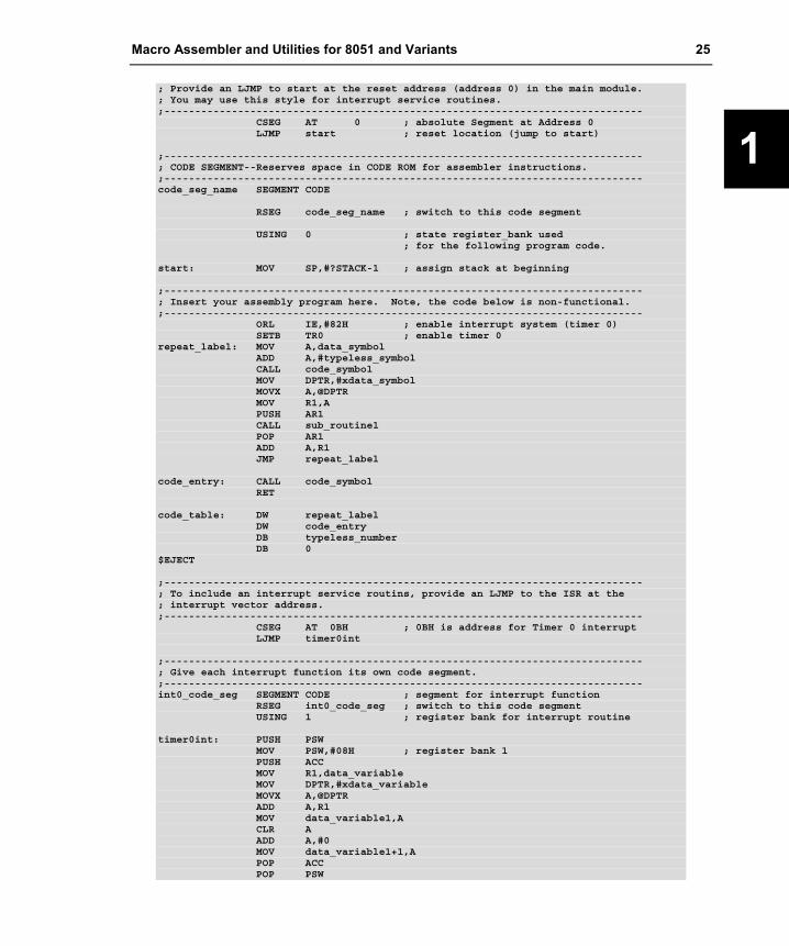
; Provide an LJMP to start at the reset address (address 0) in the main module.; You may use this style for interrupt service routines.;------------------------------------------------------------------------------
CSEG AT 0 ; absolute Segment at Address 0LJMP start ; reset location (jump to start)
;------------------------------------------------------------------------------; CODE SEGMENT--Reserves space in CODE ROM for assembler instructions.;------------------------------------------------------------------------------code_seg_name SEGMENT CODE
RSEG code_seg_name ; switch to this code segment
USING 0 ; state register_bank used; for the following program code.
start: MOV SP,#?STACK-1 ; assign stack at beginning
;------------------------------------------------------------------------------; Insert your assembly program here. Note, the code below is non-functional.;------------------------------------------------------------------------------
ORL IE,#82H ; enable interrupt system (timer 0)SETB TR0 ; enable timer 0
repeat_label: MOV A,data_symbolADD A,#typeless_symbolCALL code_symbolMOV DPTR,#xdata_symbolMOVX A,@DPTRMOV R1,APUSH AR1CALL sub_routine1POP AR1ADD A,R1JMP repeat_label
code_entry: CALL code_symbolRET
code_table: DW repeat_labelDW code_entryDB typeless_numberDB 0
$EJECT
;------------------------------------------------------------------------------; To include an interrupt service routins, provide an LJMP to the ISR at the; interrupt vector address.;------------------------------------------------------------------------------
CSEG AT 0BH ; 0BH is address for Timer 0 interruptLJMP timer0int
;------------------------------------------------------------------------------; Give each interrupt function its own code segment.;------------------------------------------------------------------------------int0_code_seg SEGMENT CODE ; segment for interrupt function
RSEG int0_code_seg ; switch to this code segmentUSING 1 ; register bank for interrupt routine
timer0int: PUSH PSWMOV PSW,#08H ; register bank 1PUSH ACCMOV R1,data_variableMOV DPTR,#xdata_variableMOVX A,@DPTRADD A,R1MOV data_variable1,ACLR AADD A,#0MOV data_variable1+1,APOP ACCPOP PSW

26 Chapter 1. Introduction
1
RETI
;------------------------------------------------------------------------------; The END directive is ALWAYS required.;------------------------------------------------------------------------------
END ; End Of File

Macro Assembler and Utilities for 8051 and Variants 27
2
Chapter 2. Architecture Overview This chapter gives you an overview of the 8051 architecture and the variants of the 8051. It reviews the memory layout of the classic 8051, extended 8051 variants, the Philips 80C51MX, and the 251 architecture. Also described are the register sets and the CPU instructions of the various CPU variants.
Memory Classes and Memory Layout This section introduces the different memory classes (also known as memory types) that are used during programming of the 8051 and variants. Memory classes are used to identify the different physical memory regions of the microcontroller architecture that can be represented in a memory layout.
An overview of the different physical memory regions in an x51 system is provided below:
Program Memory: in the classic 8051 this is a 64KB space that is called CODE. This region is typically a ROM space that is used for program code and constants. With the BL51 you may expand the physical program code memory to 32 code banks with 64KB each. Constants are fetched with the MOVC instruction. In extended 8051 variants and the 251 you may have program memory of up to 16MB that is called ECODE and HCONST.
Internal Data Memory: in the classic 8051 this is the on-chip RAM space with a maximum of 256 Bytes that contains register banks, BIT space, direct addressable DATA space, and indirect addressable IDATA space. This region should be used for frequently used variables. In the 80C51MX and the 251 this space is expanded to up to 64KB with an EDATA space.
External Data Memory: in classic 8051 devices this area, called XDATA, is off-chip RAM with a space of up to 64KB. However several new 8051 devices have additional on-chip RAM that is mapped into the XDATA space. Usually you need to enable this additional on-chip RAM via dedicated SFR registers. In extended variants and the 251 you may have external data memory of up to 16MB that is called HDATA.

28 Chapter 2. Architecture Overview
2
Classic 8051 The following table shows the memory classes used for programming the classic 8051 architecture. These memory classes are available when you are using the A51 macro assembler and the BL51 linker/locater.
Memory Class Address Range Description
DATA D:00 – D:7F Direct addressable on-chip RAM.
BIT D:20 – D:2F bit-addressable RAM; accessed bit instructions.
IDATA I:00 – I:FF Indirect addressable on-chip RAM; can be accessed with @R0 or @R1.
XDATA X:0000 – X:FFFF 64 KB RAM (read/write access). Accessed with MOVX instruction.
CODE C:0000 – C:FFFF 64 KB ROM (only read access possible). Used for executable code or constants.
BANK 0 … BANK 31
B0:0000 – B0:FFFF B31:0000 – B31:FFFF
Code Banks for expanding the program code space to 32 x 64KB ROM.
NOTE The memory prefix D: I: X: C: B0: .. B31: cannot be used at Ax51 assembler or BL51 linker/locater level. The memory prefixes are only listed for better understanding. Several Debugging tools, for example the µVision2 Debugger, are using memory prefixes to identify the memory class of the address.

Macro Assembler and Utilities for 8051 and Variants 29
2
Classic 8051 Memory Layout
The classic 8051 memory layout, shown in the following figure, is familiar to 8051 users the world over.
IDATA256 BYTE
DATA128 BYTE
I:0x100
I:0x80
D:0
DATA128 BYTE
D:0x7F
DATA
DATA FF
SFRSPACE
80
88
90
98
F8
2F
201F
0
4 Register
Banks
8051Bitspace
80
CODE
C:0000
C:FFFF
8051Bit
addressable
XDATA
X:FFFF
X:0000
BANK 0... BANK 31
Bx:0000
Bx:FFFF
The memory code banks overlap the CODE space. The size of the code banks is selected with the Lx51 directive BANKAREA.
30 Chapter 2. Architecture Overview
2
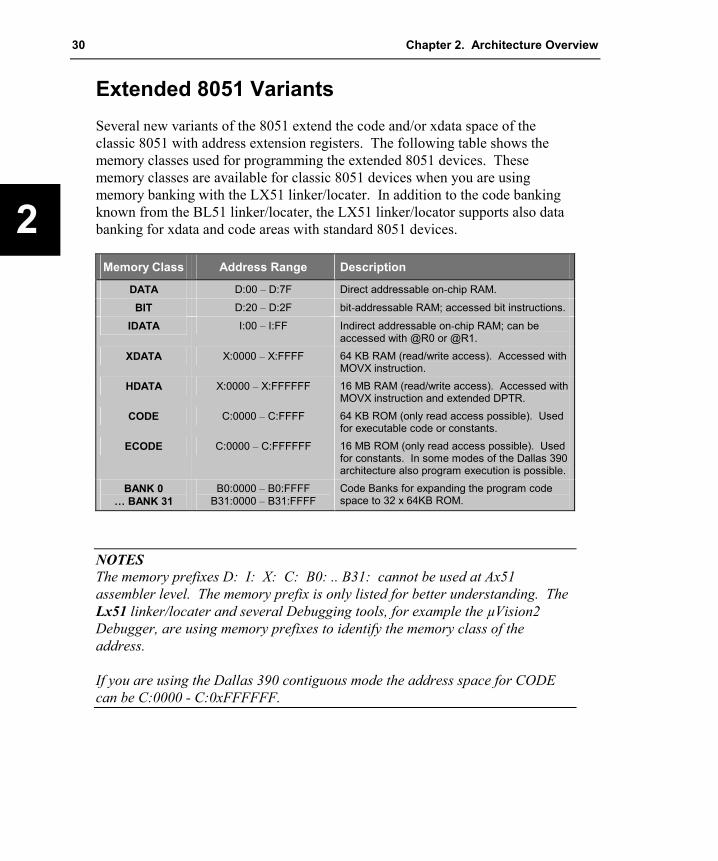
Extended 8051 Variants Several new variants of the 8051 extend the code and/or xdata space of the classic 8051 with address extension registers. The following table shows the memory classes used for programming the extended 8051 devices. These memory classes are available for classic 8051 devices when you are using memory banking with the LX51 linker/locater. In addition to the code banking known from the BL51 linker/locater, the LX51 linker/locator supports also data banking for xdata and code areas with standard 8051 devices.
Memory Class Address Range Description
DATA D:00 – D:7F Direct addressable on-chip RAM.
BIT D:20 – D:2F bit-addressable RAM; accessed bit instructions.
IDATA I:00 – I:FF Indirect addressable on-chip RAM; can be accessed with @R0 or @R1.
XDATA X:0000 – X:FFFF 64 KB RAM (read/write access). Accessed with MOVX instruction.
HDATA X:0000 – X:FFFFFF 16 MB RAM (read/write access). Accessed with MOVX instruction and extended DPTR.
CODE C:0000 – C:FFFF 64 KB ROM (only read access possible). Used for executable code or constants.
ECODE C:0000 – C:FFFFFF 16 MB ROM (only read access possible). Used for constants. In some modes of the Dallas 390 architecture also program execution is possible.
BANK 0 … BANK 31
B0:0000 – B0:FFFF B31:0000 – B31:FFFF
Code Banks for expanding the program code space to 32 x 64KB ROM.
NOTES The memory prefixes D: I: X: C: B0: .. B31: cannot be used at Ax51 assembler level. The memory prefix is only listed for better understanding. The Lx51 linker/locater and several Debugging tools, for example the µVision2 Debugger, are using memory prefixes to identify the memory class of the address. If you are using the Dallas 390 contiguous mode the address space for CODE can be C:0000 - C:0xFFFFFF.

Macro Assembler and Utilities for 8051 and Variants 31
2
Extended 8051 Memory Layout
The extended 8051 memory layout, shown in the following figure, expands the address space for variables to a maximum of 16MB.
HCONST16MBmax. addressable
HDATA16MBmax.
D:0 0
IDATA256 BYTE
DATA128 BYTE
I:0x100
I:0x80
128 BYTE
D:0x7F
DATA
DATA FF
SFRSPACE
80
88
90
98
F8
2F
201F
4 Register
Banks
8051Bitspace
80
8051Bit
XDATA
X:FFFF
X:0000
C:0000
CODEBANK 0
C:10000
BANK 1
C:20000
C:3F0000
BANK 63
C:3FFFFF
DATA
In several variants the DPTR register is expanded to a 24-bit register with an DPX SFR. Fox example, the Dallas 390 and provides new operating modes where this addressing is enabled. You may even use the HCONST and HDATA memory classes with classic 8051 devices by using the memory banking available in LX51.

32 Chapter 2. Architecture Overview
2
Philips 80C51MX The Philips 80C51MX provides a unified 16 MB address space. New instructions can access up to 16MB memory whereby CODE and XDATA space are mapped into one single address space. The stack pointer can be configured as 16-Bit stack pointer that addresses the on-chip RAM area in the EDATA memory class. The following table shows the memory classes used for programming the 80C51MX architecture. These memory classes are available when you are using the AX51 macro assembler and the LX51 linker/locater.
Memory Class Address Range Description
DATA 7F:0000 – 7F:007F Direct addressable on-chip RAM.
BIT 7F:0020 – 7F:002F Bit-addressable RAM; accessed bit instructions.
IDATA 7F:0000 – 7F:00FF Indirect addressable on-chip RAM; can be accessed with @R0 or @R1.
EDATA 7F:0000 – 7F:FFFF Complete on-chip RAM; can be used as stack space or can be accessed with @PR0 or @PR1.
XDATA 00:0000 – 00:FFFF 64 KB RAM (read/write access). Accessed with MOVX instruction.
HDATA 00:0000 – 7F:FFFF 8 MB RAM (read/write access). Accessed with MOVX instruction and extended DPTR.
CODE 80:0000 – 80:FFFF Classic 8051 compatible 64 KB ROM (only read access possible). Used for executable code or constants.
ECODE 80:0000 – 80:FFFF 8 MB ROM (only read access possible).
HCONST 80:0000 – 80:FFFF 8 MB ROM. Same as ECODE, this class is used by the CX51 Compiler for constants.
BANK 0 … BANK 63
80:0000 – 0xBF:FFFF B0:0000 – B63:FFFF
Used by the CX51 Compiler to expand the program memory to more than 64KB. Refer to “Philips 80C51MX” on page 255 for more information.
NOTES Colons are used to improve the readability only. The addresses are entered in the tools as numbers without colon. The memory prefixes D: I: X: C: B0: .. B31: cannot be used at Ax51 assembler level. The memory prefix is only listed for better understanding. The Lx51 linker/locater and several Debugging tools, for example the µVision2 Debugger, are using memory prefixes to identify the memory class of the address.

Macro Assembler and Utilities for 8051 and Variants 33
2
80C51MX Memory Layout
The Philips 80C51MX memory layout, shown in the following figure, provides a universal memory map that includes all memory types in a single 16MB address region. The memory layout of the Philips 80C51MX is shown below:
HDATA8MB
XDATA64KB
00:0000
00:FFFF
7F:FFFF
EDATA64KB
IDATA256 Bytes
DATA128 Bytes
7F:0080
7F:0000
7F:FFFF
DATA128 Bytes
DATA
DATA80
SFRSPACEDATA
DATA
80
88
90
98
2F
201F
0
4RegisterBanks
8051Bitspace
FF
7F:007F
EDATA64KB
7F:0000
7F:00FF
80:0000
CODE(= Bank 0)
64KB
ECODE8MB
FF:FFFF
The 80C51MX offers new CPU instructions that provide a new addressing mode, called Universal Pointer addressing. Two Universal Pointer registers PR0 and PR1 are available. PR0 is composed of registers R1, R2, and R3. PR1 is composed of registers R5, R6, and R7. These new Universal Pointer registers hold a 24-bit address that is used together with the EMOV instruction to address the complete 16MB memory.
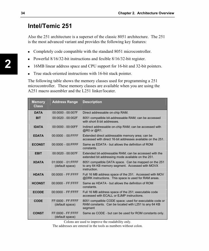
34 Chapter 2. Architecture Overview
2
Intel/Temic 251 Also the 251 architecture is a superset of the classic 8051 architecture. The 251 is the most advanced variant and provides the following key features:
�� Completely code compatible with the standard 8051 microcontroller.
�� Powerful 8/16/32-bit instructions and fexible 8/16/32-bit register.
�� 16MB linear address space and CPU support for 16-bit and 32-bit pointers.
�� True stack-oriented instructions with 16-bit stack pointer.
The following table shows the memory classes used for programming a 251 microcontroller. These memory classes are available when you are using the A251 macro assembler and the L251 linker/locater.
Memory Class
Address Range Description
DATA 00:0000 - 00:007F Direct addressable on-chip RAM.
BIT 00:0020 - 00:002F 8051 compatible bit-addressable RAM; can be accessed with short 8-bit addresses.
IDATA 00:0000 - 00:00FF Indirect addressable on-chip RAM; can be accessed with @R0 or @R1.
EDATA 00:0000 – 00:FFFF Extended direct addressable memory area; can be accessed with direct 16-bit addresses available on the 251.
ECONST 00:0000 – 00:FFFF Same as EDATA - but allows the definition of ROM constants.
EBIT 00:0020 - 00:007F Extended bit-addressable RAM; can be accessed with the extended bit addressing mode available on the 251.
XDATA 01:0000 – 01:FFFF (default space)
8051 compatible DATA space. Can be mapped on the 251 to any 64 KB memory segment. Accessed with MOVX instruction.
HDATA 00:0000 – FF:FFFF Full 16 MB address space of the 251. Accessed with MOV @DRK instructions. This space is used for RAM areas.
HCONST 00:0000 – FF:FFFF Same as HDATA - but allows the definition of ROM constants.
ECODE 00:0000 – FF:FFFF Full 16 MB address space of the 251; executable code accessed with ECALL or EJMP instructions.
CODE FF:0000 - FF:FFFF (default space)
8051 compatible CODE space; used for executable code or RAM constants. Can be located with L251 to any 64 KB segment
CONST FF:0000 - FF:FFFF (default space)
Same as CODE - but can be used for ROM constants only.
Colons are used to improve the readability only. The addresses are entered in the tools as numbers without colon.

Macro Assembler and Utilities for 8051 and Variants 35
2
251 Memory Layout
The following figure shows the memory layout of the 251 architecture.
HDATAECODEHCONST16 MB
XDATA(default,SEGMENTmapable)
EDATA64 KB
01:0000
00:0000
02:0000
CODEdefault page
FF:0000
Reset Vector
FF:FFFF
EDATA64 KB
IDATA256 Bytes
DATA128 Bytes
00:0100
00:0080
00:0000
00:FFFF
DATA128 BYTE
007F
DATA
DATA
SFRSPACE
80
88
90
98
F8
EBIT
bitaddr.251
2F
201F
0
4 RegisterBanks
8051Bitspace
FF
80
00:
The 251 completely supports all aspects of the classic 8051 memory layout and instruction set. Existing 8051 programs can be directly execute on the 251. The four 8051 memory spaces (DATA, IDATA, CODE and XDATA) are mapped into specific regions of the 16 MB address space.

36 Chapter 2. Architecture Overview
2
CPU Registers The following section provides an overview of the CPU registers that are available on the x51 variants.
In addition to the CPU registers R0 - R7, all x51 variants have an SFR space that is used to address on-chip peripherals and I/O ports. In the SFR area also reside the CPU registers SP (stack pointer), PSW (program status word), A (accumulator, accessed via the SFR space as ACC), B, DPL and DPH (16-bit register DPTR).
CPU Registers of the 8051 Variants The classic 8051 provides 4 register banks of 8 registers each. These registerbanks are mapped into the DATA memory area at address 0 – 0x1F. In addition the CPU provides a 8-bit A (accumulator) and B register and a 16-bit DPTR (data pointer) for addressing XDATA and CODE memory. These registers are also mapped into the SFR space as special function registers.
R0 R1 R2 R3 R4 R5 R6 R7
8 Bytes
CPU REGISTERDATA MEMORY
Registerbank 0D:0x00
Registerbank 1D:0x08
Registerbank 2D:0x10
Registerbank 3D:0x18
The active Registerbank is selected via the bitsRB0 and RB1 in the program status word (PSW).
PR0 PR1
Universal Pointers on Philips 80C51MX
DPH DPL A B PSW
DPTR
SP
DPX
SPX
Some CPU variants provide extendedDPTR and/or SP registers. Also severaldevices have multiple DPTR registers.

Macro Assembler and Utilities for 8051 and Variants 37
2
CPU Registers of the Intel/Temic 251 The 251 architecture supports an extra 32 bytes of registers in addition to the 4 banks of 8 registers found in the classic 8051. The lower 8 byte registers are mapped between locations 00:00 - 00:0x1F. The lower 8 byte registers are mapped in this way to support 8051 microcontroller register banking. The register file can be addressed in the following ways:
�� Register 0 - 15 can be used as either byte, word, or double word (Dword) registers.
�� Register 16 - 31 can be addressed as either word or Dword registers.
�� Register DR56 and DR60 can be addressed only as Dword registers.
�� There are 16 possible byte registers (R0 - R15), 16 possible word registers (WR0 - WR30) and 10 possible Dword registers (DR0 - DR28, DR56 - DR60) that can be addressed in any combination.
�� All Dword registers are Dword aligned; each is addressed as DRk with “k” being the lowest of the 4 consecutive registers. For example, DR4 consists of registers 4 - 7.
�� All word registers are word aligned; each is addressed as WRj with “j” being the lower of the 2 consecutive registers. For example WR4 consists of registers 4 - 5.
�� All byte registers are inherently byte aligned; each is addressed as Rm with “m” being the register number. For example R4 consists of register 4.

38 Chapter 2. Architecture Overview
2
The following figure shows the register file format for the 251 microcontroller.
WR24 WR26 WR28 WR30
WR16 WR18 WR20 WR22
WR8 WR10 WR12 WR14
WR0 WR2 WR4 WR6
R14 R15R13R12R11R10R9R8
R0 R1 R2 R3 R4 R5 R6 R7
8 Bytes
WORD REGISTER
BYTE REGISTER
DWORD REGISTER
Stack Pointer (SPX)
DR56 DR60
DR24
DR16
DR8
DR0
DR28
DR20
DR12
DR4
Stack Pointer (SPX)
DR56 DR60
DR24
WR16
WR8
WR0
WR28
DR20
R12
DR4
R13 R14 R15
WR30
WR18
WR10
R2 R3
EXAMPLE OF MIXED USAGE
Register 56 - 63
Register 8 - 31
Register 0 - 7
MEMORY
The 8051 CPU Registers A, B,DPL, DPH and SP are mapped into the 251 register file. Thefollowing 251 CPU registers areidentical with the 8051 CPUregisters: 8051 Register 251 Register A (ACC) R11 B R10 DPL low byte of DR56 DPH 2nd byte of DR56 SP low byte of DR60
The stack pointer register (DR60)of the 251 CPU is a 16-bit register. DR60 is used for all stackoperations (PUSH, POP, CALL,RET, ect.) and can be also used forindirect addressing. Therefore the251 provides efficient stackaddressing modes for reentrantfunctions.
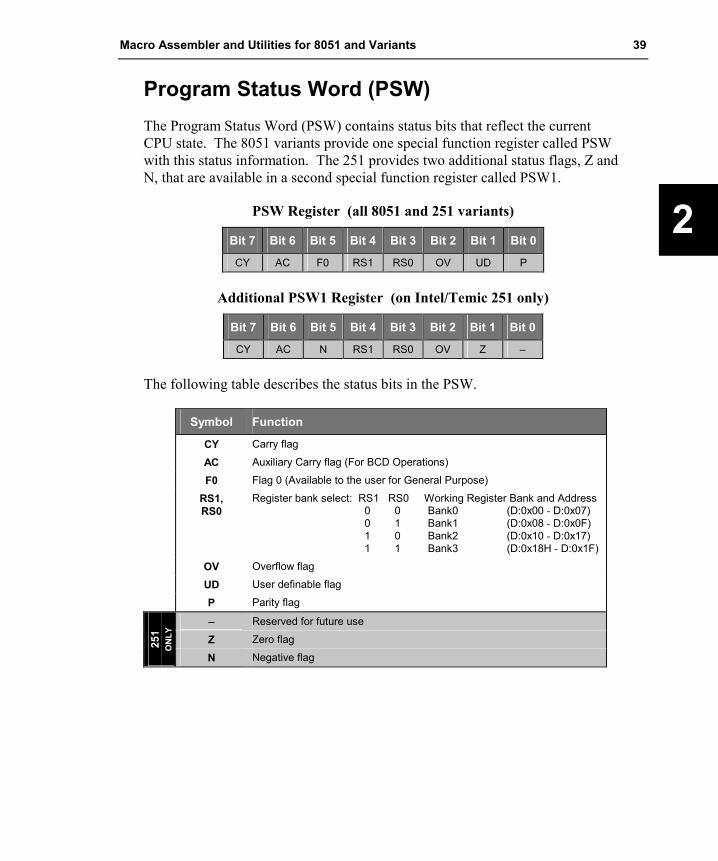
Macro Assembler and Utilities for 8051 and Variants 39
2
Program Status Word (PSW) The Program Status Word (PSW) contains status bits that reflect the current CPU state. The 8051 variants provide one special function register called PSW with this status information. The 251 provides two additional status flags, Z and N, that are available in a second special function register called PSW1.
PSW Register (all 8051 and 251 variants)
Bit 7 Bit 6 Bit 5 Bit 4 Bit 3 Bit 2 Bit 1 Bit 0
CY AC F0 RS1 RS0 OV UD P
Additional PSW1 Register (on Intel/Temic 251 only)
Bit 7 Bit 6 Bit 5 Bit 4 Bit 3 Bit 2 Bit 1 Bit 0
CY AC N RS1 RS0 OV Z –
The following table describes the status bits in the PSW.
Symbol Function
CY Carry flag
AC Auxiliary Carry flag (For BCD Operations)
F0 Flag 0 (Available to the user for General Purpose)
RS1, RS0
Register bank select: RS1 RS0 Working Register Bank and Address 0 0 Bank0 (D:0x00 - D:0x07) 0 1 Bank1 (D:0x08 - D:0x0F) 1 0 Bank2 (D:0x10 - D:0x17) 1 1 Bank3 (D:0x18H - D:0x1F)
OV Overflow flag
UD User definable flag
P Parity flag
– Reserved for future use
Z Zero flag 251
ON
LY
N Negative flag

40 Chapter 2. Architecture Overview
2
Instruction Sets This section lists the instructions of all x51 CPU variants in alphabetical order. The following terms are used in the descriptions.
Identifier Explanation
A Accumulator AB Register Pair A & B B Multiplication Register C Carry Flag DPTR Data pointer PC Program Counter Rn Register R0 - R7 of the currently selected Register Bank. dir8 8-bit data address; Data RAM (D:0x00 - D:0x7F) or SFR (D:0x80 - D:0xFF) #data8 8-bit constant included in instruction. #data16 16-bit constant included in instruction. addr16 16-bit destination address. addr11 11-bit destination address. Used by ACALL & AJMP. The branch will be within the
same 2KByte block of program memory of the first byte of the following instruction. rel Signed (two’s complement) 8-bit offset. Used by SJMP and conditional jumps.
Range is -128 .. +127 bytes relative to the first byte of the following instruction. bit8 Direct addressed bit in Data RAM Location.
Rm Register R0 - R15 of the currently selected Register File. WRj Register WR0 - WR30 of the currently selected Register File. DRk Register DR0 - DR28, DR56, DR60 of the currently selected Register File. dir16 16-bit data address; Data RAM location (00:00 - 00:FFFF). @WRj Data RAM location (0 - 64K) addressed indirectly via WR0 - WR30. @DRk Data RAM location (0 - 16M) addressed indirectly via DR0 - DR28, DR56, DR60. #short constant 1, 2 or 4 included in instruction. bit11 Direct addressed bit in Data RAM or Special Function Register. @Wrj+dis Data RAM location (0 - 64K) addressed indirectly via WR0 - WR30 + displacement.
251
ON
LY
@DRk+dis Data RAM location (0 - 16M) addressed indirectly via DR0 - DR28, DR56, DR60+ 16-bit signed displacement.
EPTR 23-bit extended data pointer register. PR0, PR1 Universal Pointer Register (PR0 represents R1,R2,R3; PR1 represents R5,R6,R7) @PR0+d2 @PR1+d2
Universal memory location (0 - 16M) addressed indirectly via PR0 or PR1+ 2-bit displacement (+0, +1, +2, +3).
#data2 2-bit constant included in instruction (value range: #1, #2, #3, #4). 51M
X O
NLY
addr23 23-bit destination address for HDATA or ECODE

Macro Assembler and Utilities for 8051 and Variants 41
2
ACALL Absolute Subroutine CALL CY—
AC —
N —
OV —
Z—
Mnemonic Description Bytes Binary
BytesSource
ACALL addr11 Absolute Subroutine Call 2 2
DALLAS 24-Bit Contiguous Address Mode ONLY ACALL addr19 Absolute Subroutine Call 3
ADD ADD destination, source Addition
CYX
AC X
N X
OV X
ZX
Mnemonic Description Bytes Binary
BytesSource
ADD A,Rn Add register to accumulator 1 2 ADD A,dir8 Add direct byte to accumulator 2 2 ADD A,@Ri Add indirect RAM to accumulator 1 2 ADD A,#data8 Add immediate data to accumulator 2 2
ADD Rm,Rm Add byte register to byte register 3 2
ADD WRj,WRj Add word register to word register 3 2
ADD DRk,DRk Add double word register to dword register 3 2
ADD Rm,#data8 Add 8 bit data to byte register 4 3
ADD Wrj,#data16 Add 16 bit data to word register 5 4
ADD Drk,#data16 Add 16 bit unsigned data to dword register 5 4
ADD Rm,dir8 Add direct address to byte register 4 3
ADD WRj,dir8 Add direct address to word register 4 3
ADD Rm,dir16 Add direct address (64K) to byte register 5 4
ADD WRj,dir16 Add direct address (64K) to word register 5 4
ADD Rm,@WRj Add indirect address (64K) to byte register 4 3
251
ON
LY
ADD Rm,@DRk Add indirect address (16M) to byte register 4 3
ADD PR0,#data2 Add immediate data to PR0 2
MX5
1
ADD PR1,#data2 Add immediate data to PR1 2
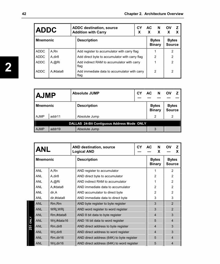
42 Chapter 2. Architecture Overview
2
ADDC ADDC destination, source Addition with Carry
CYX
ACX
N X
OV X
Z X
Mnemonic Description Bytes Binary
Bytes Source
ADDC A,Rn Add register to accumulator with carry flag 1 2 ADDC A,dir8 Add direct byte to accumulator with carry flag 2 2 ADDC A,@Ri Add indirect RAM to accumulator with carry
flag 1 2
ADDC A,#data8 Add immediate data to accumulator with carry flag
2 2
AJMP Absolute JUMP CY—
AC—
N —
OV —
Z —
Mnemonic Description Bytes Binary
Bytes Source
AJMP addr11 Absolute Jump 2 2
DALLAS 24-Bit Contiguous Address Mode ONLY AJMP addr19 Absolute Jump 3
ANL AND destination, source Logical AND
CY—
AC—
N X
OV —
Z X
Mnemonic Description Bytes Binary
Bytes Source
ANL A,Rn AND register to accumulator 1 2 ANL A,dir8 AND direct byte to accumulator 2 2 ANL A,@Ri AND indirect RAM to accumulator 1 2 ANL A,#data8 AND immediate data to accumulator 2 2 ANL dir,A AND accumulator to direct byte 2 2 ANL dir,#data8 AND immediate data to direct byte 3 3
ANL Rm,Rm AND byte register to byte register 3 2
ANL WRj,WRj AND word register to word register 3 2
ANL Rm,#data8 AND 8 bit data to byte register 4 3
ANL Wrj,#data16 AND 16 bit data to word register 5 4
ANL Rm,dir8 AND direct address to byte register 4 3
ANL Wrj,dir8 AND direct address to word register 4 3
ANL Rm,dir16 AND direct address (64K) to byte register 5 4
251
ON
LY
ANL Wrj,dir16 AND direct address (64K) to word register 5 4

Macro Assembler and Utilities for 8051 and Variants 43
2
ANL AND destination, source Logical AND
CY—
AC —
N X
OV —
ZX
Mnemonic Description Bytes Binary
BytesSource
ANL Rm,@WRj AND indirect address (64K) to byte register 4 3
ANL Rm,@DRk AND indirect address (16M) to byte register 4 3
ANL ANL destination, source Logical AND for bit variables
CYX
AC —
N —
OV —
Z—
Mnemonic Description Bytes Binary
BytesSource
ANL C,bit8 AND direct bit to carry; from BIT space 2 2
Intel/Temic 251 ONLY ANL C,bit11 AND direct bit to carry; from EBIT space 4 3
ANL/ ANL/ destination, source Logical AND for bit variables
CYX
AC —
N X
OV —
ZX
Mnemonic Description Bytes Binary
BytesSource
ANL C,/bit8 AND complement of dir bit to carry; BIT space 2 2
Intel/Temic 251 ONLY ANL C,/bit11 AND complement of dir bit to carry; EBIT
space 4 3
CJNE COMPARE destination, source and jump if not equal
CYX
AC —
N X
OV —
ZX
Mnemonic Description Bytes Binary
BytesSource
CJNE A,dir8,rel Compare dir byte to acc. and jump if not equal 3 3 CJNE /A,#data8,rel Compare imm. data to acc. and jump if not
equal 3 3
CJNE Rn,#data8,rel Compare imm. data to reg and jump if not equal
3 4
CJNE @Ri,#data8,rel Compare imm. data to indir and jump if not equal
3 4

44 Chapter 2. Architecture Overview
2
CLR CLEAR Operand CY—
AC—
N X
OV —
Z X
Mnemonic Description Bytes Binary
Bytes Source
CLR A Clear accumulator 1 1
CLR CLEAR Bit Operand CY—
AC—
N —
OV —
Z —
Mnemonic Description Bytes Binary
Bytes Source
CLR C Clear carry 1 1 CLR bit8 Clear direct bit from BIT space 2 2
Intel/Temic 251 ONLY CLR bit11 Clear direct bit from EBIT space 4 3
CMP COMPARE Operands CYX
ACX
N X
OV X
Z X
Mnemonic Description Bytes Binary
Bytes Source
CMP Rm,Rm Compare registers 3 2
CMP WRj,WRj Compare word registers 3 2
CMP DRk,DRk Compare double word registers 3 2
CMP Rm,#data8 Compare register with immediate data 4 3
CMP Wrj,#data16 Compare word register with immediate data 5 4
CMP Drk,#00 Compare dword reg with zero extended data 5 4
CMP Drk,#ff Compare dword reg with one extended data 5 4
CMP Rm,dir8 Compare register with direct byte 4 3
CMP WRj,dir8 Compare word register with direct word 4 3
CMP Rm,dir16 Compar register with direct byte (64K) 5 4
CMP WRj,dir16 Compare word register with direct word (64K) 5 4
CMP Rm,@WRj Compare register with indirect address (64K) 4 3
251
ON
LY
CMP Rm,@DRk Compare register with indirect address (16M) 4 3

Macro Assembler and Utilities for 8051 and Variants 45
2
CPL COMPLEMENT Operand CY—
AC —
N X
OV —
ZX
Mnemonic Description Bytes Binary
BytesSource
CPL A Complement accumulator 1 1
CPL COMPLEMENT Bit Operand CY—
AC —
N —
OV —
Z—
Mnemonic Description Bytes Binary
BytesSource
CPL C Complement carry 1 1 CPL bit8 Complement direct bit from BIT space 2 2
Intel/Temic 251 ONLY CPL bit11 Complement direct bit from EBIT space 4 3
DA DECIMAL ADJUST Accumulator for Addition
CYX
AC —
N X
OV —
ZX
Mnemonic Description Bytes Binary
BytesSource
DA A Decimal adjust accumulator 1 1
DEC DECREMENT Operand with a constant
CY—
AC —
N X
OV —
ZX
Mnemonic Description Bytes Binary
BytesSource
DEC A Decrement accumulator 1 1 DEC Rn Decrement register 1 2 DEC dir Decrement dir byte 2 2 DEC @Ri Decrement indir RAM 1 2
Intel/Temic 251 ONLY DEC Rm,#short Decrement byte register with 1, 2 or 4 3 2 DEC WRj,#short Decrement word register with 1, 2 or 4 3 2 DEC DRk,#short Decrement double word register with 1, 2 or 4 3 2

46 Chapter 2. Architecture Overview
2
DIV DIVIDE Operands CY0
AC—
N X
OV X
Z X
Mnemonic Description Bytes Binary
Bytes Source
DIV AB Divide A by B 1 1
Intel/Temic 251 ONLY DIV Rm,Rm Divide byte register by byte register 3 2 DIV WRj,WRj Divide word register by word register 3 2
DJNZ DECREMENT Operand and Jump if Not Zero
CY—
AC—
N X
OV —
Z X
Mnemonic Description Bytes Binary
Bytes Source
DJNZ Rn,rel Decrement register and jump if not zero 2 3 DJNZ dir8,rel Decrement direct byte and jump if not zero 3 3
ECALL Extended Subroutine CALL CY—
AC—
N —
OV —
Z —
Mnemonic Description Bytes Binary
Bytes Source
Intel/Temic 251 ONLY ECALL addr24 Extended subroutine call 5 4 ECALL DRk Extended subroutine call 3 2
Philips 80C51MX ONLY ECALL addr23 Extended subroutine Call 5
EJMP Extended JUMP CY—
AC—
N —
OV —
Z —
Mnemonic Description Bytes Binary
Bytes Source
Intel/Temic 251 ONLY EJMP addr24 Extended jump 5 4 EJMP DRk Extended jump 3 2
Philips 80C51MX ONLY

Macro Assembler and Utilities for 8051 and Variants 47
2
EJMP Extended JUMP CY—
AC —
N —
OV —
Z—
Mnemonic Description Bytes Binary
BytesSource
EJMP addr23 Extended jump 5
EMOV MOV destination, source Move data via Unversal Pointer
CY—
AC —
N —
OV —
Z—
Mnemonic Description Bytes Binary
BytesSource
EMOV A,@PR0+d2 Move indirect (16M) via Universal Pointer to A 2
EMOV A,@PR1+d2 Move indirect (16M) via Universal Pointer to A 2
EMOV @PR0+d2,A Move A to indirect (16M) via Universal Pointer 2
51M
X O
NLY
EMOV @PR1+d2,A Move A to indirect (16M) via Universal Pointer 2
ERET RETURN from extended Subroutine
CY—
AC —
N —
OV —
Z—
Mnemonic Description Bytes Binary
BytesSource
251&
51M
X O
NLY
ERET Return from subroutine 2 1
INC INCREMENT Operand with a constant
CY—
AC —
N X
OV —
ZX
Mnemonic Description Bytes Binary
BytesSource
INC A Increment accumulator 1 1 INC Rn Increment register 1 2 INC dir Increment direct byte 2 2 INC @Ri Increment indirect RAM 1 2 INC DPTR Increment Data Pointer 1 1
INC Rm,#short Increment byte register with 1, 2 or 4 3 2 INC WRj,#short Increment word register with 1, 2 or 4 3 2
251
ON
LY
INC Drk,#short Increment double word register with 1, 2 or 4 3 2
Philips 80C51MX ONLY
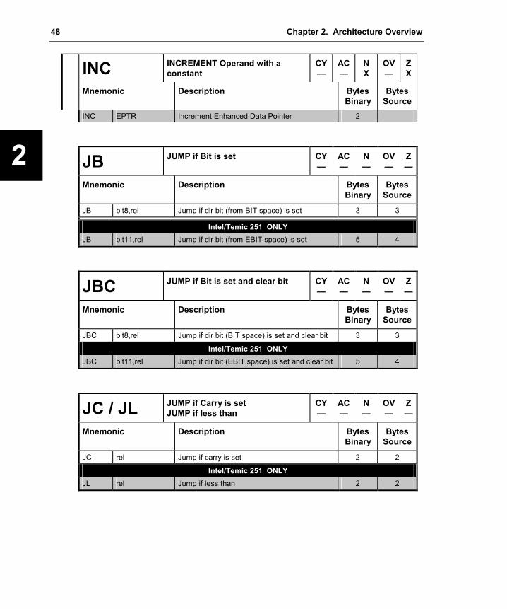
48 Chapter 2. Architecture Overview
2
INC INCREMENT Operand with a constant
CY—
AC—
N X
OV —
Z X
Mnemonic Description Bytes Binary
Bytes Source
INC EPTR Increment Enhanced Data Pointer 2
JB JUMP if Bit is set CY—
AC—
N —
OV —
Z —
Mnemonic Description Bytes Binary
Bytes Source
JB bit8,rel Jump if dir bit (from BIT space) is set 3 3
Intel/Temic 251 ONLY JB bit11,rel Jump if dir bit (from EBIT space) is set 5 4
JBC JUMP if Bit is set and clear bit CY—
AC—
N —
OV —
Z —
Mnemonic Description Bytes Binary
Bytes Source
JBC bit8,rel Jump if dir bit (BIT space) is set and clear bit 3 3
Intel/Temic 251 ONLY JBC bit11,rel Jump if dir bit (EBIT space) is set and clear bit 5 4
JC / JL JUMP if Carry is set JUMP if less than
CY—
AC—
N —
OV —
Z —
Mnemonic Description Bytes Binary
Bytes Source
JC rel Jump if carry is set 2 2
Intel/Temic 251 ONLY JL rel Jump if less than 2 2
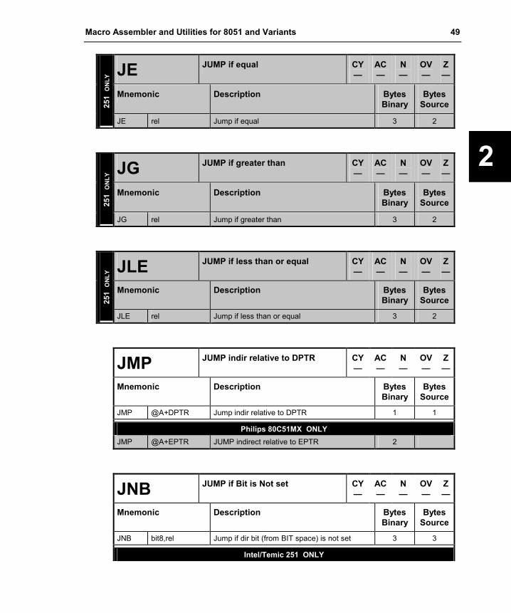
Macro Assembler and Utilities for 8051 and Variants 49
2
JE JUMP if equal CY—
AC —
N —
OV —
Z—
Mnemonic Description Bytes Binary
BytesSource 25
1 O
NLY
JE rel Jump if equal 3 2
JG JUMP if greater than CY—
AC —
N —
OV —
Z—
Mnemonic Description Bytes Binary
BytesSource 25
1 O
NLY
JG rel Jump if greater than 3 2
JLE JUMP if less than or equal CY—
AC —
N —
OV —
Z—
Mnemonic Description Bytes Binary
BytesSource 25
1 O
NLY
JLE rel Jump if less than or equal 3 2
JMP JUMP indir relative to DPTR CY—
AC —
N —
OV —
Z—
Mnemonic Description Bytes Binary
BytesSource
JMP @A+DPTR Jump indir relative to DPTR 1 1
Philips 80C51MX ONLY JMP @A+EPTR JUMP indirect relative to EPTR 2
JNB JUMP if Bit is Not set CY—
AC —
N —
OV —
Z—
Mnemonic Description Bytes Binary
BytesSource
JNB bit8,rel Jump if dir bit (from BIT space) is not set 3 3
Intel/Temic 251 ONLY

50 Chapter 2. Architecture Overview
2
JNB JUMP if Bit is Not set CY—
AC—
N —
OV —
Z —
Mnemonic Description Bytes Binary
Bytes Source
JNB bit11,rel Jump if dir bit (from EBIT space) is not set 5 4
JNC / JGE JUMP if Carry is Not set JUMP if greater than or equal
CY—
AC—
N —
OV —
Z —
Mnemonic Description Bytes Binary
Bytes Source
JNC rel Jump if carry is not set 2 2
Intel/Temic 251 ONLY JGE rel Jump if greater than or equal 2 2
JNE JUMP if Not Equal CY—
AC—
N —
OV —
Z —
Mnemonic Description Bytes Binary
Bytes Source 25
1 O
NLY
JNE rel Jump if not equal 3 2
JNZ JUMP if Accumulator is Not Zero CY—
AC—
N —
OV —
Z —
Mnemonic Description Bytes Binary
Bytes Source
JNZ rel Jump if accumulator is not zero 2 2
JSG JUMP if greater than (Signed) CY—
AC—
N —
OV —
Z —
Mnemonic Description Bytes Binary
Bytes Source 25
1 O
NLY
JSG rel Jump if greater than (signed) 3 2

Macro Assembler and Utilities for 8051 and Variants 51
2
JSGE JUMP if greater than or Equal (Signed)
CY—
AC —
N —
OV —
Z—
Mnemonic Description Bytes Binary
BytesSource 25
1 O
NLY
JSGE rel Jump if greater than or equal (signed) 3 2
JSL JUMP if Less than (Signed) CY—
AC —
N —
OV —
Z—
Mnemonic Description Bytes Binary
BytesSource 25
1 O
NLY
JSL rel Jump if less than (signed) 3 2
JSLE JUMP if Less than or Equal (Signed)
CY—
AC —
N —
OV —
Z—
Mnemonic Description Bytes Binary
BytesSource 25
1 O
NLY
JSLE rel Jump if less than or equal (signed) 3 2
JZ JUMP if Accumulator is Zero CY—
AC —
N —
OV —
Z—
Mnemonic Description Bytes Binary
BytesSource
JZ rel Jump if accumulator is zero 2 2
LCALL Long Subroutine CALL CY—
AC —
N —
OV —
Z—
Mnemonic Description Bytes Binary
BytesSource
LCALL addr16 Long Subroutine Call 3 3
Intel/Temic 251 ONLY LJMP @WRj Long Jump indirect via word register 3 2
DALLAS 24-Bit Contiguous Address Mode ONLY

52 Chapter 2. Architecture Overview
2
LCALL Long Subroutine CALL CY—
AC—
N —
OV —
Z —
Mnemonic Description Bytes Binary
Bytes Source
LCALL addr24 Absolute Subroutine Call 4
LJMP Long JUMP CY—
AC—
N —
OV —
Z —
Mnemonic Description Bytes Binary
Bytes Source
LJMP addr16 Long Jump 3 3
Intel/Temic 251 ONLY LJMP @WRj Long Jump indirect via word register 3 2
DALLAS 24-Bit Contiguous Address Mode ONLY LJMP addr24 Absolute Subroutine Call 4
MOV MOV destination, source Move data
CY—
AC—
N —
OV —
Z —
Mnemonic Description Bytes Binary
Bytes Source
MOV A,Rn Move register to accumulator 1 2 MOV A,dir8 Move direct byte to accumulator 2 2 MOV A,@Ri Move indirect RAM to accumulator 1 2 MOV A,#data8 Move immediate data to accumulator 2 2 MOV Rn,A Move accumulator to register 1 2 MOV Rn,dir8 Move direct byte to register 2 3 MOV Rn,#data8 Move immediate data to register 2 3 MOV dir8,A Move accumulator to direct byte 2 2 MOV dir8,Rn Move register to direct byte 2 3 MOV dir8,dir8 Move direct byte to direct byte 3 3 MOV dir8,@Ri Move indirect RAM to direct byte 2 3 MOV dir8,#data8 Move immediate data to direct byte 3 3 MOV @Ri,A Move accumulator to indirect RAM 1 2 MOV @Ri,dir8 Move direct byte to indirect RAM 2 3 MOV @Ri,#data8 Move immediate data to indirect RAM 2 3 MOV DPTR,#data16 Load Data Pointer with 16-bit constant 3 3

Macro Assembler and Utilities for 8051 and Variants 53
2
MOV MOV destination, source Move data
CY—
AC —
N —
OV —
Z—
Mnemonic Description Bytes Binary
BytesSource
MOV C,bit8 Move dir bit to carry 2 2 MOV bit8,C Move carry to dir bit 2 2
MOV Rm,Rm Move byte register to byte register 3 2
MOV WRj,WRj Move word register to word register 3 2
MOV DRk,DRk Move dword register to dword register 3 2
MOV Rm,#data8 Move 8 bit data to byte register 4 3
MOV WRj,#data16 Move 16 bit data to word register 5 4
MOV DRk,#0data16 Move 16 bit zero extended data to dword reg. 5 4
MOV DRk,#1data16 Move 16 bit one extended data to dword reg. 5 4
MOV Rm,dir8 Move dir address to byte register 4 3
MOV WRj,dir8 Move direct address to word register 4 3
MOV DRk,dir8 Move direct address to dword register 4 3
MOV Rm,dir16 Move direct address (64K) to byte register 5 4
MOV WRj,dir16 Move direct address (64K) to word register 5 4
MOV DRk,dir16 Move direct address (64K) to dword register 5 4
MOV Rm,@WRj Move indirect address (64K) to byte register 4 3
MOV Rm,@DRk Move indirect address (16M) to byte register 4 3
MOV WRj,@WRj Move indirect address (64K) to word register 4 3
MOV WRj,@DRk Move indirect address (16M) to word register 4 3
MOV dir8,Rm Move byte register to direct address 4 3
MOV dir8,WRj Move word register to direct address 4 3
MOV dir8,DRk Move dword register to direct address 4 3
MOV dir16,Rm Move byte register to direct address (64K) 5 4
MOV dir16,WRj Move word register to direct address (64K) 5 4
MOV dir16,DRk Move dword register to direct address (64K) 5 4
MOV @WRj,Rm Move byte register to direct address (64K) 4 3
MOV @DRk,Rm Move byte register to indirect address (16M) 4 3
MOV @WRj,WRj Move word register to indirect address (64K) 4 3
MOV @DRk,WRj Move word register to indirect address (16M) 4 3
MOV Rm,@WRj+dis Move displacement address (64K) to byte reg. 5 4
MOV WRj,@WRj+dis Move displacement address (64K) to word reg. 5 4
MOV Rm,@DRk+dis Move displacement address (16M) to byte reg. 5 4
MOV WRj,@DRk+dis Move displacement address (16M) to word reg.
5 4
251
ON
LY
MOV @WRj+dis,Rm Move byte reg. to displacement address (64K) 5 4

54 Chapter 2. Architecture Overview
2
MOV MOV destination, source Move data
CY—
AC—
N —
OV —
Z —
Mnemonic Description Bytes Binary
Bytes Source
MOV @WRj+dis,WRj Move word reg. to displacement address (64K) 5 4
MOV @DRk+dis,Rm Move byte reg. to displacement address (16M) 5 4
MOV @DRk+dis,WRj Move word reg. to displacement address (16M)
5 4
MOV C,bit11 Move dir bit from 8 bit address location to carry
2 2
MOV bit11,C Move carry to dir bit from 16 bit address location
5 4
Philips 80C51MX ONLY MOV EPTR,#adr23 Load extended data pointer with constant 5
MOVC MOV destination, source Move Code byte
CY—
AC—
N —
OV —
Z —
Mnemonic Description Bytes Binary
Bytes Source
MOVC A,@A+DPTR Move code byte relative to DPTR to accumulator
1 1
MOVC A,@A+PC Move code byte relative to PC to accumulator 1 1
Philips 80C51MX ONLY MOVC A,@A+EPTR Move code byte relative to EPTR to
accumulator 2
MOVH MOVH destination, source Move data to high word of DR
CY—
AC—
N —
OV —
Z —
Mnemonic Description Bytes Binary
Bytes Source 25
1 O
NLY
MOVH DRk,#data16 Move 16bit imm. data to high word of dword reg.
3 2
251
MOVS MOVS destination, source Move byte to word (signed ext.)
CY—
AC—
N —
OV —
Z —

Macro Assembler and Utilities for 8051 and Variants 55
2
Mnemonic Description Bytes Binary
BytesSource
MOVS WRj,Rm Move byte register to word register 3 2
MOVX MOV destination, source External RAM access
CY—
AC —
N —
OV —
Z—
Mnemonic Description Bytes Binary
BytesSource
MOVX A,@Ri Move xdata RAM (8 bit address) to accumulator
1 2
MOVX A,@DPTR Move xdata RAM (16 bit address) to accumulator
1 1
MOVX @Ri,A Move accumulator to xdata RAM (8 bit address)
1 2
MOVX @DPTR,A Move accumulator to xdata RAM (16 bit address)
1 1
Philips 80C51MX ONLY MOVX @EPTR,A Move accu to xdata RAM (23 bit address) 2 MOVX A,@EPTR Move xdata RAM (23 bit address) to accu 2
MOVZ MOV destination, source Move byte to word (zero ext.)
CY—
AC —
N —
OV —
Z—
Mnemonic Description Bytes Binary
BytesSource 25
1 O
NLY
MOVZ WRj,Rm Move byte reg. to word reg. (zero extended) 3 2
MUL MULTIPLY Operands CY0
AC —
N X
OV X
ZX
Mnemonic Description Bytes Binary
BytesSource
MUL AB Multiply A and B 1 1
Intel/Temic 251 ONLY MUL Rm,Rm Multiply byte register with byte register 3 2 MUL WRj,WRj Multiply word register with word register 3 2

56 Chapter 2. Architecture Overview
2
NOP No Operation CY—
AC—
N —
OV —
Z —
Mnemonic Description Bytes Binary
Bytes Source
NOP No operation 1 1
ORL ORL destination, source Logical OR
CY—
AC—
N X
OV —
Z X
Mnemonic Description Bytes Binary
Bytes Source
ORL A,Rn OR register to accumulator 1 2 ORL A,dir8 OR dir byte to accumulator 2 2
ORL A,@Ri OR indir RAM to accumulator 1 2 ORL A,#data8 OR immediate data to accumulator 2 2 ORL dir,A OR accumulator to dir byte 2 2 ORL dir,#data8 OR immediate data to dir byte 3 3
ORL Rm,Rm OR byte register to byte register 3 2
ORL WRj,WRj OR word register to word register 3 2
ORL Rm,#data8 OR 8 bit data to byte register 4 3
ORL WRj,#data16 OR 16 bit data to word register 5 4
ORL Rm,dir8 OR dir address to byte register 4 3
ORL WRj,dir8 OR dir address to word register 4 3
ORL Rm,dir16 OR dir address (64K) to byte register 5 4
ORL WRj,dir16 OR dir address (64K) to word register 5 4
ORL Rm,@WRj OR indir address (64K) to byte register 4 3
251
ON
LY
ORL Rm,@DRk OR indir address (16M) to byte register 4 3
ORL ORL destination, source Logical OR for bit variables
CYX
AC—
N —
OV —
Z —
Mnemonic Description Bytes Binary
Bytes Source
ORL C,bit8 OR direct bit to carry; from BIT space 2 2
Intel/Temic 251 ONLY ORL C,bit11 OR direct bit to carry; from EBIT space 4 3
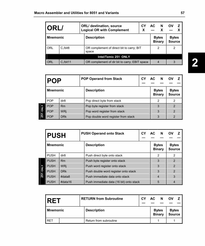
Macro Assembler and Utilities for 8051 and Variants 57
2
ORL/ ORL/ destination, source Logical OR with Complement
CYX
AC —
N X
OV —
ZX
Mnemonic Description Bytes Binary
BytesSource
ORL C,/bit8 OR complement of direct bit to carry; BIT space
2 2
Intel/Temic 251 ONLY ORL C,/bit11 OR complement of dir bit to carry; EBIT space 4 3
POP POP Operand from Stack CY—
AC —
N —
OV —
Z—
Mnemonic Description Bytes Binary
BytesSource
POP dir8 Pop direct byte from stack 2 2
POP Rm Pop byte register from stack 3 2
POP WRj Pop word register from stack 3 2
251
ON
LY
POP DRk Pop double word register from stack 3 2
PUSH PUSH Operand onto Stack CY—
AC —
N —
OV —
Z—
Mnemonic Description Bytes Binary
BytesSource
PUSH dir8 Push direct byte onto stack 2 2
PUSH Rm Push byte register onto stack 3 2
PUSH WRj Push word register onto stack 3 2
PUSH DRk Push double word register onto stack 3 2
PUSH #data8 Push immediate data onto stack 4 3 251
ON
LY
PUSH #data16 Push immediate data (16 bit) onto stack 5 4
RET RETURN from Subroutine CY—
AC —
N —
OV —
Z—
Mnemonic Description Bytes Binary
BytesSource
RET Return from subroutine 1 1

58 Chapter 2. Architecture Overview
2
RETI RETURN from Interrupt CY—
AC—
N —
OV —
Z —
Mnemonic Description Bytes Binary
Bytes Source
RETI Return from interrupt 1 1
RL ROTATE Accumulator Left CY—
AC—
N X
OV —
Z X
Mnemonic Description Bytes Binary
Bytes Source
RL A Rotate accumulator left 1 1
RLC ROTATE Accumulator Left through the Carry
CYX
AC—
N X
OV —
Z X
Mnemonic Description Bytes Binary
Bytes Source
RLC A Rotate accumulator left through the carry 1 1
RR ROTATE Accumulator Right CY—
AC—
N X
OV —
Z X
Mnemonic Description Bytes Binary
Bytes Source
RR A Rotate accumulator right 1 1
RRC ROTATE Accumulator Right through the Carry
CYX
AC—
N X
OV —
Z X
Mnemonic Description Bytes Binary
Bytes Source
RRC A Rotate accumulator right through the carry 1 1

Macro Assembler and Utilities for 8051 and Variants 59
2
SETB SET Bit Operand CY—
AC —
N —
OV —
Z—
Mnemonic Description Bytes Binary
BytesSource
SETB C Set carry 1 1 SETB bit8 Set direct bit from BIT space 2 2
Intel/Temic 251 ONLY SETB bit11 Set direct bit from EBIT space 5 4
SJMP Short JUMP CY—
AC —
N —
OV —
Z—
Mnemonic Description Bytes Binary
BytesSource
SJMP rel Short jump (relative address) 2 2
SLL SHIFT Register Left CYX
AC —
N X
OV —
ZX
Mnemonic Description Bytes Binary
BytesSource
SLL Rm Shift byte register left 3 2
251
ON
LY
SLL WRj Shift word register left 3 2
SRA SHIFT Register Right (arithmet.) sign extended
CYX
AC —
N X
OV —
ZX
Mnemonic Description Bytes Binary
BytesSource
SRA Rm Shift byte register right; sign extended 3 2
251
ON
LY
SRA WRj Shift word register right; sign extended 3 2
SRL SHIFT Register Right (logic) zero extended
CYX
AC —
N X
OV —
ZX
251
ON
LY
Mnemonic Description Bytes Binary
BytesSource

60 Chapter 2. Architecture Overview
2
SRL SHIFT Register Right (logic) zero extended
CYX
AC—
N X
OV —
Z X
Mnemonic Description Bytes Binary
Bytes Source
SRL Rm Shift byte register right; zero extended 3 2
SRL WRj Shift word register right; zero extended 3 2
SUB SUB destination, source Subtraction
CYX
ACX
N X
OV X
Z X
Mnemonic Description Bytes Binary
Bytes Source
SUB Rm,Rm Subtract byte register from byte register 3 2
SUB WRj,WRj Subtract word register from word register 3 2
SUB DRk,DRk Subtract dword register from dregister 3 2
SUB Rm,#data Subtract 8 bit data from byte register 4 3
SUB Wrj,#data16 Subtract 16 bit data from word register 5 4
SUB Drk,#data16 Subtract 16 bit unsigned data from dword reg. 5 4
SUB Rm,dir Subtract direct address from byte register 4 3
SUB Wrj,dir Subtract direct address from word register 4 3
SUB Rm,dir16 Subtract direct address (64K) from byte register
5 4
SUB Wrj,dir16 Subtract direct address (64K) from word register
5 4
SUB Rm,@WRj Subtract indirect address (64K) from byte reg. 4 3
251
ON
LY
SUB Rm,@DRk Subtract indirect address (16M) from byte reg. 4 3
SUBB SUBB destination, source Subtraction with Borrow
CYX
ACX
N X
OV X
Z X
Mnemonic Description Bytes Binary
Bytes Source
SUBB A,Rn Subtract register from accumulator with borrow 1 2 SUBB A,dir8 Subtract direct byte from accumulator with
borrow 2 2
SUBB A,@Ri Subtract indirect byte from accumulator with borrow
1 2
SUBB A,#data8 Subtract immediate data from accumulator with borrow
2 2

Macro Assembler and Utilities for 8051 and Variants 61
2
SWAP SWAP Nibbles within the Accumulator
CY—
AC —
N X
OV —
ZX
Mnemonic Description Bytes Binary
BytesSource
SWAP A Swap nibbles within the accumulator 1 1
TRAP JUMP to the Trap Interrupt CY—
AC —
N —
OV —
Z—
Mnemonic Description Bytes Binary
BytesSource 25
1 O
NLY
TRAP Jumps to the trap interrupt vector 2 1
XCH EXCHANGE Operands CY—
AC —
N —
OV —
Z—
Mnemonic Description Bytes Binary
BytesSource
XCH A,Rn Exchange register with accumulator 2 2 XCH A,dir8 Exchange direct byte with accumulator 2 2 XCH A,@Ri Exchange indirect byte with accumulator 1 2
XCHD EXCHANGE Digit CY—
AC —
N —
OV —
Z—
Mnemonic Description Bytes Binary
BytesSource
XCHD A,@Ri Exchange low-order digit in indir. RAM with accumulator
1 2
XRL EXCL.-OR destination, source Logical Exclusive-OR
CY—
AC —
N X
OV —
ZX
Mnemonic Description Bytes Binary
BytesSource
XRL A,Rn Exclusive-OR register to accumulator 1 2 XRL A,dir8 Exclusive-OR direct byte to accumulator 2 2

62 Chapter 2. Architecture Overview
2
XRL EXCL.-OR destination, source Logical Exclusive-OR
CY—
AC—
N X
OV —
Z X
Mnemonic Description Bytes Binary
Bytes Source
XRL A,@Ri Exclusive-OR indirect byte to accumulator 1 2 XRL A,#data8 Exclusive-OR immediate data to accumulator 2 2 XRL dir8,A Exclusive-OR accumulator to direct byte 2 2 XRL dir8,#data8 Exclusive-OR immediate data to direct byte 3 3
XRL Rm,Rm Exclusive-OR byte register to byte register 3 2
XRL WRj,WRj Exclusive-OR word register to word register 3 2
XRL Rm,#data8 Exclusive-OR 8 bit data to byte register 4 3
XRL WRj,#data16 Exclusive-OR 16 bit data to word register 5 4
XRL Rm,dir8 Exclusive-OR direct address to byte register 4 3
XRL WRj,dir8 Exclusive-OR direct address to word register 4 3
XRL Rm,dir16 Exclusive-OR direct address (64K) to byte reg. 5 4
XRL WRj,dir16 Exclusive-OR direct address (64K) to word reg.
5 4
XRL Rm,@WRj Exclusive-OR indirect address (64K) to byte reg.
4 3
251
ON
LY
XRL Rm,@DRk Exclusive-OR indirect address (16M) to byte reg.
4 3

Macro Assembler and Utilities for 8051 and Variants 63
2
Opcode Map The following opcode maps provide an overview of the instruction encoding for the 8051, the 80C51MX, and the 251 architecture. It is arranged as separate maps as described below: 8051 Instructions: this opcodes are available on all x51 variants. Both the Philips 80C51MX and the Intel/Temic 251 use an OPCODE PREFIX byte with the encoding A5 to extend the classic 8051 instruction set. The additional 251 an 80C51MX instructions are described in the following tables.
Additional 251 Instructions: if the 251 is configured in binary mode the 8051 instructions are the default opcode map and the OPCODE PREFIX is the first opcode byte for the additional 251 instructions. If the 251 is configured in source mode the additional 251 instructions are the default opcode map and the OPCODE PREFIX is the first op-code byte when the 251 should execute standard 8051 instructions that are encode with the byte values x6 - xF.
Additional 80C51MX Instructions via Prefix A5: contains the 80C51MX instructions that require the OPCODE PREFIX byte. The Philips 80C51MX provides instructions for addressing the 16MB address space and the extended SFR area that are listed in this table.

64 Chapter 2. Architecture Overview
2
8051 Instructions Binary Mode
x0 x1 x2 x3 x4 x5 x6 - x7 x8 - xF
Source Mode
x0 x1 x2 x3 x4 x5 A5x6- A5x7
A5x8-A5xF
0x NOP AJMP adr11
LJMP adr16
RR A
INC A
INC dir
INC @Ri
INC Rn
1x JBC bit,rel
ACALL adr11
LCALL adr16
RRC A
DEC A
DEC dir
DEC @Ri
DEC Rn
2x JB bit,rel
AJMP adr11
RET RL A
ADD A,#data
ADD A,dir
ADD A,@Ri
ADD A,Rn
3x JNB bit,rel
ACALL adr11
RETI RLC A
ADDC A,#data
ADDC A,dir
ADDC A,@Ri
ADDC A,Rn
4x JC rel
AJMP adr11
ORL dir,A
ORL dir,#data
ORL A,#data
ORL A,dir
ORL A,@Ri
ORL A,Rn
5x JNC rel
ACALL adr11
ANL dir,A
ANL dir,#data
ANL A,#data
ANL A,dir
ANL A,@Ri
ANL A,Rn
6x JZ rel
AJMP adr11
XRL dir,A
XRL dir,#data
XRL A,#data
XRL A,dir
XRL A,@Ri
XRL A,Rn
7x JNZ rel
ACALL adr11
ORL c,bit
JMP @A+DPTR
MOV A,#data
MOV dir,#data
MOV @Ri,#data
MOV Rn,#data
8x SJMP rel
AJMP adr11
ANL C,bit
MOVC A,@A+PC
DIV AB
MOV dir,dir
MOV dir,@Ri
MOV dir,Rn
9x MOV DPTR,#d16
ACALL adr11
MOV bit,c
MOVC A,@A+DPTR
SUBB A,#data
SUBB A,dir
SUBB A,@Ri
SUBB A,Rn
Ax ORL C,/bit
AJMP adr11
MOV C,bit
INC DPTR
MUL AB
OPCODEPREFIX
MOV @Ri,dir
MOV Rn,dir
Bx ANL C,/bit
ACALL adr11
CPL bit
CPL C
CJNE A,#d8,rel
CJNE A,dir,rel
CJNE @Ri,#d8,rel
CJNE Rn,#d8,rel
Cx PUSH dir
AJMP adr11
CLR bit
CLR C
SWAP A
XCH A,dir
XCH A,@Ri
XCH A,Rn
Dx POP dir
ACALL adr11
SETB bit
SETB C
DA A
DJNZ dir,rel
XCHD A,@Ri
DJNZ Rn,rel
Ex MOVX A,@DPTR
AJMP adr11
MOVX A,@Ri
CLR A
MOV A,dir
MOV A,@Ri
MOV A,Rn
Fx MOV @DPTR,A
ACALL adr11
MOVX @Ri,A
CPL A
MOV dir,A
MOV @Ri,A
MOV Rn,A

Macro Assembler and Utilities for 8051 and Variants 65
2
Additional 251 Instructions Binary Mode
A5x8 A5x9 A5xA A5xB A5xC A5xD A5xE A5xF
Source Mode
x8 x9 xA xB xC xD xE xF
0 JSLE rel
MOV Rm @WRj+dis
MOVZ WRj,Rm
INC Rm/WRj/ Drk,#short
MOV reg,ind
SRA reg
1 JSG rel
MOV@WRj +dis,Rm
MOVS WRj,Rm
DEC Rm/WRj/ Drk,#short
MOV ind,reg
SRL reg
2 JLE rel
MOV Rm, @DRk+dis
ADD Rm,Rm
ADD WRj,WRj
ADD reg,op2
ADD DRk,DRk
3 JG rel
MOV@DRk +dis,Rm
SLL reg
4 JSL rel
MOV Wrj, @WRjj+dis
ORL Rm,Rm
ORL WRj,WRj
ORL reg,op2
5 JSGE rel
MOV@WRj + dis,WRj
ANL Rm,Rm
ANL WRj,WRj
ANL reg,op2
6 JE rel
MOV Wrj, @DRk+dis
XRL Rm,Rm
XRL WRj,WRj
XRL reg,op2
7 JNE rel
MOV @Drk +dis,WRj
MOV op1,reg
MOV Rm,Rm
MOV WRj,WRj
MOV reg,op2
MOV DRk,DRk
8 LJMP@WRjEJMP@DRk
EJMP addr24
DIV Rm,Rm
DIV WRj,WRj
9 LCALL@WRECALL@DRk
ECALL addr24
SUB Rm,Rm
SUB WRj,WRj
SUB reg,op2
SUB DRk,DRk
A BIT instructions
ERET MUL Rm,Rm
MUL WRj,WRj
B TRAP CMP Rm,Rm
CMP WRj,WRj
CMP reg,op2
CMP DRk,DRk
C PUSH op1
D POP op1
E
F

66 Chapter 2. Architecture Overview
2
Additional 80C51MX Instructions via Prefix A5 A5 x0 A5
x1 A5 x2 A5 x3 A5
x4 A5 x5 A5 x6 -
A5 x7 A5 x8 - A5 xF
A5 x8 - A5 xF
A5 0x EJMP adr23
INC esfr
A5 1x JBC esbit,rel
ECALL adr23
DEC esfr
A5 2x JB esbit,rel
ADD A,esfr
A5 3x JNB esbit,rel
ADDC A,esfr
A5 4x ORL esfr,A
ORL esfr,#data
ORL A,esfr
EMOV A,@PR0+d2
EMOV A,@PR1+d2
A5 5x ANL esfr,A
ANL esfr,#data
ANL A,esfr
EMOV @PR0+d2,A
EMOV @PR1+d2,A
A5 6x XRL esfr,A
XRL esfr,#data
XRL A,esfr
ADD PR0,#data2
ADD PR1,#data2
A5 7x ORL c,esbit
EJMP @A+EPTR
MOV dir,#data
A5 8x ANL C,esbit
MOV esfr,esfr
MOV esfr,@Ri
MOV esfr,Rn
A5 9x MOV EPTR,#d23
MOV esbit,c
MOVC A,@A+EPTR
SUBB A,esfr
A5 Ax ORL C,/esbit
MOV C,esbit
INC EPTR
MOV @Ri,esfr
MOV Rn,esfr
A5 Bx ANL C,/esbit
CPL esbit
CJNE A,esfr,rel
A5 Cx PUSH esfr
CLR esbit
XCH A,esfr
A5 Dx POP esfr
SETB esbit
DJNZ esfr,rel
A5 Ex MOVX A,@EPTR
MOV A,esfr
A5 Fx MOV @EPTR,A
MOV esfr,A

Macro Assembler and Utilities for 8051 and Variants 67
Directives or options with shading are available in AX51 and A251 only
3
Chapter 3. Writing Assembly Programs The Ax51 macro assembler is a multi pass assembler that translates x51 assembly language programs into object files. These object files are then combined or linked using the Lx51 Linker/Locator to form an executable, ready to run, absolute object module. As a subsequent step, absolute object modules can be converted to Intel HEX files suitable for loading onto to your target hardware, device programmer, or ICE (In-Circuit Emulator) unit.
The following sections describe the components of an assembly program, and some aspects of writing assembly programs. An assembly program consists of one or more statements. These statements contain directives, controls, and instructions.
Assembly Statements Assembly program source files are made up of statements that may include assembler controls, assembler directives, or x51 assembly language instructions (mnemonics). For example:
$TITLE(Demo Program #1)CSEG AT 0000hJMP $END
This example program consists of four statements. $TITLE is an assembler control, CSEG and END are assembler directives, and JMP is an assembly language instruction.
Each line of an assembly program can contain only one control, directive, or instruction statement. Statements must be contained in exactly one line. Multi–line statements are not allowed.
Statements in x51 assembly programs are not column sensitive. Controls, directives, and instructions may start in any column. Indentation used in the examples in this manual, is done for program clarity and is neither required nor expected by the assembler. The only exception is that arguments and instruction operands must be separated from controls, directives, and instructions by at least one space.

68 Chapter 3. Writing Assembly Programs
Directives or options with shading are available in AX51 and A251 only
3
All x51 assembly programs must include the END directive. This directive signals to the assembler that this is the end of the assembly program. Any instructions, directives, or controls found after the END directive are ignored. The shortest valid assembly program contains only an END directive.
Directives Assembler directives instruct the assembler how to process subsequent assembly language instructions. Directives also provide a way for you to define program constants and reserve space for variables.
“Chapter 4. Assembler Directives” on page 95 provides complete descriptions and examples of all of the assembler directives that you may include in your program. Refer to this chapter for more information about how to use directives.
Controls Assembler controls direct the operation of the assembler when generating a listing file or object file. Typically, controls do not impact the code that is generated by the assembler. Controls can be specified on the command line or within an assembler source file.
The conditional assembly controls are the only assembler controls that will impact the code that is assembled by the Ax51 assembler. The IF, ELSE, ENDIF, and ELSEIF controls provide a powerful set of conditional operators that can be used to include or exclude certain parts of your program from the assembly.
“Chapter 7. Invocation and Controls” on page 179 describes the available assembler controls in detail and provides an example of each. Refer to this chapter for more information about control statements.
Instructions Assembly language instructions specify the program code that is to be assembled by the Ax51 assembler. The Ax51 assembler translates the assembly instructions in your program into machine code and stores the resulting code in an object file.

Macro Assembler and Utilities for 8051 and Variants 69
Directives or options with shading are available in AX51 and A251 only
3
Assembly instructions have the following general format:
�label:� mnemonic �operand� �, operand� �, operand� �; comment�
where
label is a symbol name that is assigned the address at which the instruction is located.
mnemonic is the ASCII text string that symbolically represents a machine language instruction.
operand is an argument that is required by the specified mnemonic.
comment is an optional description or explanation of the instruction. A comment may contain any text you wish. Comments are ignored by the assembler.
The “Instruction Sets” of the x51 microcontrollers are listed on page 40 by mnemonic and by machine language opcode. Refer to this section for more information about assembler instructions.
Comments Comments are lines of text that you may include in your program to identify and explain the program. Comments are ignored by the Ax51 assembler and are not required in order to generate working programs.
You can include comments anywhere in your assembler program. Comments must be preceded with a semicolon character (;). A comment can appear on a line by itself or can appear at the end of an instruction. For example:
;This is a commentNOP ;This is also a comment
When the assembler recognizes the semicolon character on a line, it ignores subsequent text on that line. Anything that appears on a line to the right of a semicolon will be ignored by the Ax51 assembler. Comments have no impact on object file generation or the code contained therein.

70 Chapter 3. Writing Assembly Programs
Directives or options with shading are available in AX51 and A251 only
3
Symbols A symbol is a name that you define to represent a value, text block, address, or register name. You can also use symbols to represent numeric constants and expressions.
Symbol Names Symbols are composed of up to 31 characters from the following list:
A - Z, a - z, 0 - 9, _, and ?
A symbol name can start with any of these characters except the digits 0 - 9.
Symbols can be defined in a number of ways. You can define a symbol to represent an expression using the EQU or SET directives:
NUMBER_FIVE EQU 5TRUE_FLAG SET 1FALSE_FLAG SET 0
You can define a symbol to be a label in your assembly program:
LABEL1: DJNZ R0, LABEL1
You can define a symbol to refer to a variable location:
SERIAL_BUFFER DATA 99h
Symbols are used throughout assembly programs. A symbolic name is much easier to understand and remember than an address or numeric constant. The following sections provide more information about how to use and define symbols.
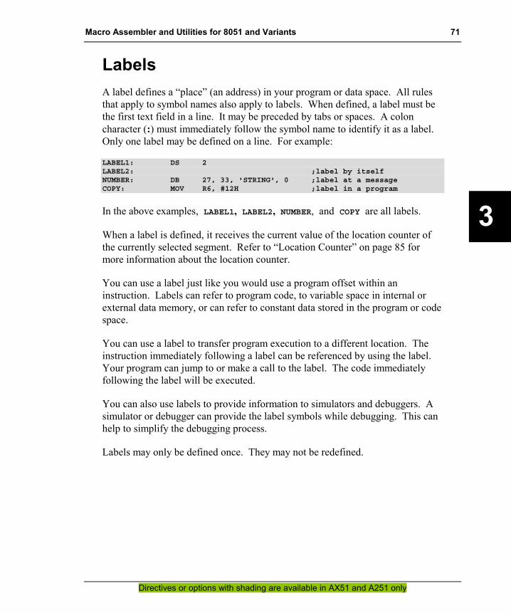
Macro Assembler and Utilities for 8051 and Variants 71
Directives or options with shading are available in AX51 and A251 only
3
Labels A label defines a “place” (an address) in your program or data space. All rules that apply to symbol names also apply to labels. When defined, a label must be the first text field in a line. It may be preceded by tabs or spaces. A colon character (:) must immediately follow the symbol name to identify it as a label. Only one label may be defined on a line. For example:
LABEL1: DS 2LABEL2: ;label by itselfNUMBER: DB 27, 33, 'STRING', 0 ;label at a messageCOPY: MOV R6, #12H ;label in a program
In the above examples, LABEL1, LABEL2, NUMBER, and COPY are all labels.
When a label is defined, it receives the current value of the location counter of the currently selected segment. Refer to “Location Counter” on page 85 for more information about the location counter.
You can use a label just like you would use a program offset within an instruction. Labels can refer to program code, to variable space in internal or external data memory, or can refer to constant data stored in the program or code space.
You can use a label to transfer program execution to a different location. The instruction immediately following a label can be referenced by using the label. Your program can jump to or make a call to the label. The code immediately following the label will be executed.
You can also use labels to provide information to simulators and debuggers. A simulator or debugger can provide the label symbols while debugging. This can help to simplify the debugging process.
Labels may only be defined once. They may not be redefined.

72 Chapter 3. Writing Assembly Programs
Directives or options with shading are available in AX51 and A251 only
3
Operands Operands are arguments, or expressions, that are specified along with assembler directives or instructions. Assembler directives require operands that are constants or symbols. For example:
VVV EQU 3DS 10h
Assembler instructions support a wider variety of operands than do directives. Some instructions require no operands and some may require up to 3 operands. Multiple operands are separated by commas. For example:
MOV R2, #0
The number of operands that are required and their types depend on the instruction or directive that is specified. In the following table the first four operands can also be expressions. Instruction operands can be classified as one the following types:
Operand Type Description
Immediate Data Symbols or constants the are used as an numeric value. Direct Bit Address Symbols or constants that reference a bit address. Program Addresses Symbols or constants that reference a code address. Direct Data Addresses Symbols or constants that reference a data address. Indirect Addresses Indirect reference to a memory location, optionally with offset. Special Assembler Symbol Register names.

Macro Assembler and Utilities for 8051 and Variants 73
Directives or options with shading are available in AX51 and A251 only
3
Special Assembler Symbols The Ax51 assembler defines and reserves names of the x51 register set. These predefined names are used in x51 programs to access the processor registers. Following, is a list of the each of the 8051, 80C51MX, and 251 registers along with a brief description:
Register Description
A Represents the 8051 Accumulator. It is used with many operations including multiplication and division, moving data to and from external memory, boolean operations, etc.
DPTR The DPTR register is a 16-bit data pointer used to address data in XDATA or CODE memory.
PC The PC register is the 16-bit program counter. It contains the address of the next instruction to be executed.
C The Carry flag; indicates the status of operations that generate a carry bit. It is also used by operations that require a borrow bit.
AB The A and B register pair used in MUL and DIV instructions.
R0 – R7 The eight 8-bit general purpose 8051 registers in the currently active register bank. A Maximum of four register banks are available.
AR0 – AR7 Represent the absolute data addresses of R0 through R7 in the current register bank. The absolute address for these registers will change depending on the register bank that is currently selected. These symbols are only available when the USING directive is given. Refer to the USING directive for more information on selecting the register bank. These representations are suppressed by the NOAREGS directive. Refer to the NOAREGS directive for more information.
PR0, PR1 Universal Pointer Registers of the 80C51MX architecture. Universal Pointer can access the complete 16MB address space of the 80C51MX. PR0 is composed of registers R1, R2, and R3. PR1 is composed of registers R5, R6, and R7.
51M
X O
NLY
EPTR Additional extended data pointer register of the 80C51MX architecture. EPTR may be used to access the complete memory space.
R8 – R15 Additional eight 8–bit general purpose registers of the 251.
WR0 – WR30
Sixteen 16–bit general purpose registers of the 251. The registers WR0 - WR14 overlap the registers R0 - R15. Note that there is no WR1 available.
251
ON
LY
DR0 – DR28 DR56, DR60
Ten 32-bit general purpose registers of 251. The registers DR0 - DR28 overlap the registers WR0 - WR30. Note that there is no DR1, DR2 and DR3 available.

74 Chapter 3. Writing Assembly Programs
Directives or options with shading are available in AX51 and A251 only
3
Immediate Data An immediate data operand is a numeric expression that is encoded as a part of the machine language instruction. Immediate data values are used literally in an instruction to change the contents of a register or memory location. The pound (or number) sign (#) must precede any expression that is to be used as an immediate data operand. The following shows some examples of how the immediate data is typically used:
MY_VAL EQU 50H ; an equate symbol
MOV A,IO_PORT2 ; direct memory access to DATAMOV A,#0E0h ; load 0xE0 into the accumulatorMOV DPTR,#0x8000 ; load 0x8000 into the data pointerANL A,#128 ; AND the accumulator with 128XRL A,#0FFh ; XOR A with 0ffhMOV R5,#MY_VAL ; load R5 with the value of MY_VAL
Memory Access A memory access reads or writes a value in to the various memory spaces of the x51 system.
Direct memory access encodes the memory address in the instruction that to reads or writes the memory. With direct memory accesses you can access variables in the memory class DATA and BIT. For the 251 also the EDATA memory class is addressable with direct memory accesses.
Indirect memory accesses uses the content of a register in the instruction that reads or writes into the memory. With indirect address operands it is possible to access all memory classes of the x51.
The following examples show how to access the different memory classes of an x51 system.

Macro Assembler and Utilities for 8051 and Variants 75
Directives or options with shading are available in AX51 and A251 only
3
DATA
Memory locations in the memory class DATA can be addressed with both: direct and indirect memory accesses. Special Function Registers (SFR) of the x51 have addresses above 0x80 in the DATA memory class. SFR locations can be addressed only with direct memory accesses. An indirect memory access to SFRs is not supported in the x51 microcontrollers.
Example for all 8051 variants ?DT?myvar SEGMENT DATA ; define a SEGMENT of class DATA
RSEG ?DT?myvarVALUE: DS 1 ; reserve 1 BYTE in DATA space
IO_PORT2 DATA 0A0H ; special function registerVALUE2 DATA 20H ; absolute memory location
?PR?myprog SEGMENT CODE ; define a segment for program codeRSEG ?PR?myprogMOV A,IO_PORT2 ; direct memory access to DATAADD A,VALUEMOV VALUE2,AMOV R1,#VALUE ; load address of VALUE to R1ADD A,@R1 ; indirect memory access to VALUE
BIT
Memory locations in the memory class BIT are addressed with the bit instructions of the 8051. Also the Special Function Registers (SFR) that are located bit-addressable memory locations can be addressed with bit instructions. Bit-addressable SFR locations are: 80H, 88H, 90H, 98H, 0A0H, 0A8H, 0B0H, 0B8H, 0C0H, 0C8H, 0D0H, 0D8H, 0E0H, 0E8H, 0F0H, and 0F8H.
Example for all 8051 variants ?BI?mybits SEGMENT BIT ; define a SEGMENT of class BIT
RSEG ?BI?mybitsFLAG: DBIT 1 ; reserve 1 Bit in BIT spaceP1 DATA 90H ; 8051 SFR PORT1GREEN_LED BIT P1.2 ; GREEN LED on I/O PORT P1.2
?PR?myprog SEGMENT CODE ; define a segment for program codeRSEG ?PR?myprogSETB GREEN_LED ; P1.2 = 1JB FLAG,is_on ; direct memory access to DATASETB FLAGCLR ACC.5 ; reset bit 5 in register A:
is_on: CLR FLAGCLR GREEN_LED ; P1.2 = 0

76 Chapter 3. Writing Assembly Programs
Directives or options with shading are available in AX51 and A251 only
3
EBIT (only on Intel/Temic 251)
The 251 provides with the EBIT memory class an expanded bit-addressable memory space that is addressed with extended bit instructions. Also all Special Function Registers (SFR) in the 251 can be addressed with extended bit instructions.
Example for Intel/Temic 251 ?EB?mybits SEGMENT EBIT ; define a SEGMENT of class EBIT
RSEG ?EB?mybitsFLAG: DBIT 1 ; reserve 1 Bit in BIT spaceCMOD DATA 0D9H ; PCA Counter ModesCPS0 BIT CMOD.1 ; CPS0 bit
?PR?myprog SEGMENT CODE ; define a segment for program codeRSEG ?PR?myprogJB FLAG,is_on ; direct memory access to DATASETB FLAG:
is_on: CLR FLAGCLR CPS0 ; CMOD.1 = 0
IDATA
Variables in this memory class are accessed via registers R0 or R1.
Example for all 8051 variants ?ID?myvars SEGMENT IDATA ; define a SEGMENT of class IDATA
RSEG ?EB?mybitsBUFFER: DS 100 ; reserve 100 Bytes
?PR?myprog SEGMENT CODE ; define a segment for program codeRSEG ?PR?myprogMOV R0,#BUFFER ; load the address in R0MOV A,@R0 ; read memory location bufferINC R0 ; increment memory address in R0MOV @R0,A ; write memory location buffer+1

Macro Assembler and Utilities for 8051 and Variants 77
Directives or options with shading are available in AX51 and A251 only
3
EDATA (Intel/Temic 251 and Philips 80C51MX only)
The EDATA memory is only available in the Philips 80C51MX and the Intel/Temic 251 architecture.
In the Philips 80C51MX, the EDATA memory can be accessed via EPTR or the Universal Pointers PR0 and PR1. Universal Pointers can access any memory location in the 16MB address space.
Example for Philips 80C51MX ?ED?my_seg SEGMENT EDATA ; define a SEGMENT of class EDATA
RSEG ?ED?my_segSTRING: DS 100 ; reserve 100 Bytes
?PR?myprog SEGMENT CODE ; define a segment for program codeRSEG ?PR?myprogMOV R1,#BYTE0 STRING ; load address of STRING in PR0MOV R2,#BYTE1 STRINGMOV R3,#BYTE2 STRINGMOV A,@PR0 ; load first byte of STRING in A
In the 251, EDATA memory can be accessed with direct memory addressing or indirect via the registers WR0 .. WR30. Also the memory class IDATA and DATA can be access with this addressing mode.
Example for Intel/Temic 251 ?ED?my_seg SEGMENT EDATA ; define a SEGMENT of class EDATA
RSEG ?ED?my_segSTRING: DS 100 ; reserve 100 Bytes
?PR?myprog SEGMENT CODE ; define a segment for program codeRSEG ?PR?myprogMOV R11,STRING+2 ; load character at STRING[2]MOV WR4,#STRING ; load address of STRINGMOV R6,@WR4 ; indirect accessMOV @WR4+2,R6 ; access with constant offset
XDATA
The XDATA memory class can be accessed with the instruction MOVX via the register DPTR. A single page of the XDATA memory can be also accessed or via the registers R0, R1. At the C Compiler level this memory type is called pdata and the segment prefix ?PD? is used. The high address for this pdata page is typically set with the P2 register. But in new 8051 variants there are also dedicated special function registers that define the XDATA page address.
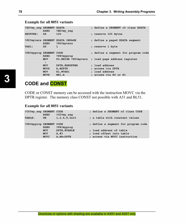
78 Chapter 3. Writing Assembly Programs
Directives or options with shading are available in AX51 and A251 only
3
Example for all 8051 variants ?XD?my_seg SEGMENT XDATA ; define a SEGMENT of class XDATA
RSEG ?ED?my_segXBUFFER: DS 100 ; reserve 100 Bytes
?PD?myvars SEGMENT XDATA INPAGE ; define a paged XDATA segmentRSEG ?PD?myvars
VAR1: DS 1 ; reserve 1 byte
?PR?myprog SEGMENT CODE ; define a segment for program codeRSEG ?PR?myprogMOV P2,#HIGH ?PD?myvars ; load page address register:MOV DPTR,#XBUFFER ; load addressMOVX A,@DPTR ; access via DPTRMOV R1,#VAR1 ; load addressMOVX @R1,A ; access via R0 or R1
CODE and CONST
CODE or CONST memory can be accessed with the instruction MOVC via the DPTR register. The memory class CONST not possible with A51 and BL51.
Example for all 8051 variants ?CO?my_seg SEGMENT CODE ; define a SEGMENT of class CODE
RSEG ?CO?my_segTABLE: DB 1,2,4,8,0x10 ; a table with constant values
?PR?myprog SEGMENT CODE ; define a segment for program codeRSEG ?PR?myprogMOV DPTR,#TABLE ; load address of tableMOV A,#3 ; load offset into tableMOVC A,@A+DPTR ; access via MOVC instruction

Macro Assembler and Utilities for 8051 and Variants 79
Directives or options with shading are available in AX51 and A251 only
3
HDATA and HCONST
The HDATA and HCONST memory can be accessed with CPU instructions only in the Philips 80C51MX and the 251 architecture. HDATA and HCONST memory is simulated with memory banking on classic 8051 devices. The HDATA and HCONST memory class is not possible with A51 and BL51.
In the Philips 80C51MX, the HDATA and HCONST memory can be accessed via EPTR or the Universal Pointers PR0 and PR1. Universal Pointers can access any memory location in the 16MB address space.
Example for Philips 80C51MX ?HD?my_seg SEGMENT HDATA ; define a SEGMENT of class HDATA
RSEG ?HD?my_segARRAY: DS 100 ; reserve 100 Bytes
?PR?myprog SEGMENT CODE ; define a segment for program codeRSEG ?PR?myprogMOV R1,#BYTE0 ARRAY ; load address of ARRAY in PR0MOV R2,#BYTE1 ARRAYMOV R3,#BYTE2 ARRAYMOV A,@PR0 ; load first byte of ARRAY in A
In the 251, HDATA and HCONST memory can be accessed via the registers DR0 .. DR28 and DR56. Any memory location can be accessed with this registers.
Example for Intel/Temic 251 ?HD?my_seg SEGMENT HDATA ; define a SEGMENT of class HDATA
RSEG ?HD?my_segARRAY: DS 100 ; reserve 100 Bytes
?PR?myprog SEGMENT CODE ; define a segment for program codeRSEG ?PR?myprogMOV WR8,#WORD2 ARRAY ; load address of ARRAYMOV WR10,#WORD0 ARRAY ; into DR8MOV R4,@DR8 ; indirect accessMOV @DR8+50H,R4 ; access with constant offset

80 Chapter 3. Writing Assembly Programs
Directives or options with shading are available in AX51 and A251 only
3
Program Addresses Program addresses are absolute or relocatable expressions with the memory class CODE or ECODE. Typically program addresses are used in jump and call instructions. For indirect jumps or calls it is required to load a program address in a register or a jump table. The following jumps and calls are possible:
SJMP JZ JNZ …
Relative jumps include conditional jumps (CJNE, DJNZ, JB, JBC, JC, …) and the unconditional SJMP instruction. The addressable offset is –128 to +127 bytes from the first byte of the instruction that follows the relative jump. When you use a relative jump in your code, you must use an expression that evaluates to the code address of the jump destination. The assembler does all the offset computations. If the address is out of range, the assembler will issue an error message.
ACALL AJMP
In-block jumps and calls permit access only within a 2KByte block of program space. The low order 11 bits of the program counter are replaced when the jump or call is executed. For Dallas 390 contiguous mode the block size is 512KB or 19 bits. If ACALL or AJMP is the last instruction in a block, the high order bits of the program counter change and the jump will be within the block following the ACALL or AJMP.
LCALL LJMP
Long jumps and calls allow access to any address within a 64KByte segment of program space. The low order 16 bits of the program counter are replaced when the jump or call is executed. For Dallas 390 contiguous mode: the block size is 16MB or 24 bits. One Philips 80C51MX and Intel/Temic 251: if LCALL or LJMP is the last instruction in a 64KByte segment, the high order bits of the program counter change and the jump will into the segment following the LCALL or LJMP.
ECALL EJMP
Extended jumps and calls allow access within the extended program space of the Intel/Temic 251 or Philips 80C51MX.
CALL JMP
Generic jumps and calls are two instruction mnemonics that do not represent a specific opcode. JMP may assemble to SJMP, AJMP, LJMP or EJMP. CALL may assemble to ACALL, LCALL or ECALL. These generic mnemonics always evaluate to an instruction, not necessarily the shortest, that will reach the specified program address operand.
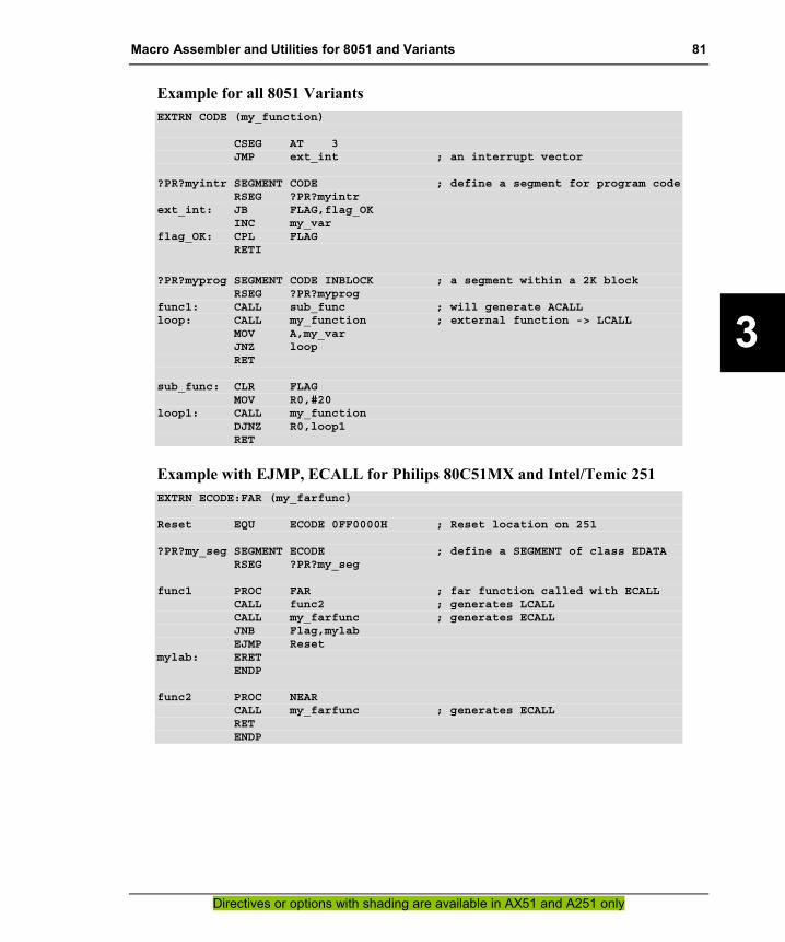
Macro Assembler and Utilities for 8051 and Variants 81
Directives or options with shading are available in AX51 and A251 only
3
Example for all 8051 Variants EXTRN CODE (my_function)
CSEG AT 3JMP ext_int ; an interrupt vector
?PR?myintr SEGMENT CODE ; define a segment for program codeRSEG ?PR?myintr
ext_int: JB FLAG,flag_OKINC my_var
flag_OK: CPL FLAGRETI
?PR?myprog SEGMENT CODE INBLOCK ; a segment within a 2K blockRSEG ?PR?myprog
func1: CALL sub_func ; will generate ACALLloop: CALL my_function ; external function -> LCALL
MOV A,my_varJNZ loopRET
sub_func: CLR FLAGMOV R0,#20
loop1: CALL my_functionDJNZ R0,loop1RET
Example with EJMP, ECALL for Philips 80C51MX and Intel/Temic 251 EXTRN ECODE:FAR (my_farfunc)
Reset EQU ECODE 0FF0000H ; Reset location on 251
?PR?my_seg SEGMENT ECODE ; define a SEGMENT of class EDATARSEG ?PR?my_seg
func1 PROC FAR ; far function called with ECALLCALL func2 ; generates LCALLCALL my_farfunc ; generates ECALLJNB Flag,mylabEJMP Reset
mylab: ERETENDP
func2 PROC NEARCALL my_farfunc ; generates ECALLRETENDP
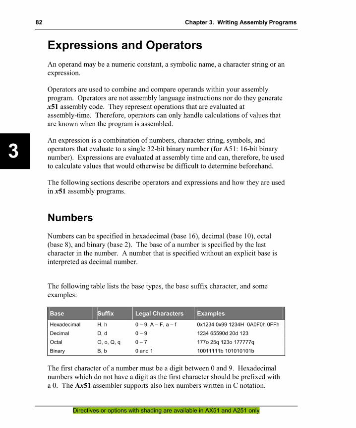
82 Chapter 3. Writing Assembly Programs
Directives or options with shading are available in AX51 and A251 only
3
Expressions and Operators An operand may be a numeric constant, a symbolic name, a character string or an expression.
Operators are used to combine and compare operands within your assembly program. Operators are not assembly language instructions nor do they generate x51 assembly code. They represent operations that are evaluated at assembly-time. Therefore, operators can only handle calculations of values that are known when the program is assembled.
An expression is a combination of numbers, character string, symbols, and operators that evaluate to a single 32-bit binary number (for A51: 16-bit binary number). Expressions are evaluated at assembly time and can, therefore, be used to calculate values that would otherwise be difficult to determine beforehand.
The following sections describe operators and expressions and how they are used in x51 assembly programs.
Numbers Numbers can be specified in hexadecimal (base 16), decimal (base 10), octal (base 8), and binary (base 2). The base of a number is specified by the last character in the number. A number that is specified without an explicit base is interpreted as decimal number.
The following table lists the base types, the base suffix character, and some examples:
Base Suffix Legal Characters Examples
Hexadecimal H, h 0 – 9, A – F, a – f 0x1234 0x99 1234H 0A0F0h 0FFh Decimal D, d 0 – 9 1234 65590d 20d 123 Octal O, o, Q, q 0 – 7 177o 25q 123o 177777q Binary B, b 0 and 1 10011111b 101010101b
The first character of a number must be a digit between 0 and 9. Hexadecimal numbers which do not have a digit as the first character should be prefixed with a 0. The Ax51 assembler supports also hex numbers written in C notation.

Macro Assembler and Utilities for 8051 and Variants 83
Directives or options with shading are available in AX51 and A251 only
3
The dollar sign character ($) can be used in a number to make it more readable, however, the dollar sign character cannot be the first or last character in the number. A dollar sign used within a number is ignored by the assembler and has no impact on the value of the number. For example:
1111$0000$1010$0011b is equivalent to 1111000010100011B1$2$3$4 is equivalent to 1234
Colon Notation for Numbers (A251 only)
A251 supports the notation page:number for specifying absolute addresses. Numbers specified with this notation receive the memory type EDATA when page is 0 or ECODE for all other pages. In this way, you can use such numbers for referencing any memory location. For example:
ABSVAL1 EQU 0:20H ; symbol to address location 20HABSVAL2 EQU 0:80H ; symbol to address location 80H in EDATA spacePORT0 EQU S:80H ; symbol to SFR space 80HENTRY EQU 10:2000H ; entry point at location 102000H
MOV WR0,ABSVAL1MOV R1,ABSVAL2MOV PORT0,R1EJMP ENTRYMOV WR0,0:20H ; access to ABSVAL1MOV R1,0:80H ; access to ABSVAL2MOV S:80H,R1EJMP 10:2000H
The colon notation is accepted in several A251 controls and is converted as described.
Number in Colon Notation Replaced with
VAL1 EQU 0:20H VAL1 EQU EDATA 20H VAL2 EQU 0FF:1000H VAL2 EQU ECODE 0FF1000H ORG 0FE:2000H ?modulename?number SEGMENT ECODE AT 0FE2000H
RSEG ?modulename?number ORG 0:400H ?modulename?number SEGMENT EDATA AT 400H
RSEG ?modulename?number CSEG AT 0FE:2000H ?modulename?number SEGMENT ECODE AT 0FE2000H
RSEG ?modulename?number BVAR1 BIT 0:20H.1 BVAR1 BIT 20H.1 BVAR1 BIT 0:30H.1 BVAR1 EQU EBIT 30H.1 PUSH.B #13 PUSH BYTE #13 PUSH.W #13 PUSH WORD #13

84 Chapter 3. Writing Assembly Programs
Directives or options with shading are available in AX51 and A251 only
3
NOTE The colon notation is provided for source compatibility with other 251 macro assemblers. If you do not need to port your code to other assemblers, it is recommended to use directly the replacement sequence in your assembler source file.
Characters The Ax51 assembler allows you to use ASCII characters in an expression to generate a numeric value. Up to two characters enclosed within single quotes (') may be included in an expression. More than two characters in single quotes in an expression will cause the Ax51 assembler to generate an error. Following are examples of character expressions:
'A' evaluates to 0041h'AB' evaluates to 4142h'a' evaluates to 0061h'ab' evaluates to 6162h'' null string evaluates to 0000h'abc' generates an ERROR
Characters may be used anywhere in your program as a immediate data operand. For example:
LETTER_A EQU 'A'
TEST: MOV @R0, #'F'SUBB A, #'0'
Character Strings Character strings can be used in combination with the DB directive to define messages that are used in your x51 assembly program. Character strings must be enclosed within single quotes ('). For example:
KEYMSG: DB 'Press any key to continue.'
generates the hexadecimal data (50h, 72h, 65h, 73h, 73h, 20h, … 6Eh, 75h, 65h, 2Eh) starting at KEYMSG. You can mix string and numeric data on the same line. For example:
EOLMSG: DB 'End of line', 00h

Macro Assembler and Utilities for 8051 and Variants 85
Directives or options with shading are available in AX51 and A251 only
3
appends the value 00h to the end of the string 'End of line'.
Two successive single quote characters can be used to insert a single quote into a string. For example:
MSGTXT: DB 'ISN''T A QUOTE REQUIRED HERE?'.
Location Counter The Ax51 assembler maintains a location counter for each segment. The location counter contains the offset of the instruction or data being assembled and is incremented after each line by the number of bytes of data or code in that line.
The location counter is initialized to 0 for each segment, but can be changed using the ORG directive.
The dollar sign character ($) returns the current value of the location counter. This operator allows you to use the location counter in an expression. For example, the following code uses $ to calculate the length of a message string.
MSG: DB 'This is a message', 0MSGLEN EQU $ – MSG
You can also use $ in an instruction. For example, the following line of code will repeat forever.
JMP $ ; repeat forever
Operators The Ax51 assembler provides several classes of operators that allow you to compare and combine operands and expressions. These operators are described in the sections that follow.
Arithmetic Operators
Arithmetic operators perform arithmetic functions like addition, subtraction, multiplication, and division. These operators require one or two operands depending on the operation. The result is always a 16-bit value. Overflow and
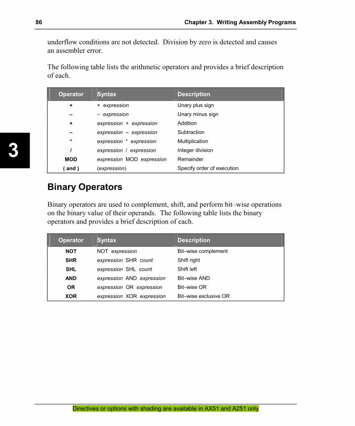
86 Chapter 3. Writing Assembly Programs
Directives or options with shading are available in AX51 and A251 only
3
underflow conditions are not detected. Division by zero is detected and causes an assembler error.
The following table lists the arithmetic operators and provides a brief description of each.
Operator Syntax Description
+ + expression Unary plus sign
– – expression Unary minus sign
+ expression + expression Addition
– expression – expression Subtraction
* expression * expression Multiplication
/ expression / expression Integer division
MOD expression MOD expression Remainder
( and ) (expression) Specify order of execution
Binary Operators
Binary operators are used to complement, shift, and perform bit–wise operations on the binary value of their operands. The following table lists the binary operators and provides a brief description of each.
Operator Syntax Description
NOT NOT expression Bit–wise complement
SHR expression SHR count Shift right
SHL expression SHL count Shift left
AND expression AND expression Bit–wise AND
OR expression OR expression Bit–wise OR
XOR expression XOR expression Bit–wise exclusive OR

Macro Assembler and Utilities for 8051 and Variants 87
Directives or options with shading are available in AX51 and A251 only
3
Relational Operators
The relational operators compare two operands. The result of the comparison is a TRUE or FALSE. A FALSE result has a value of 0000h. A TRUE result has a non–zero value.
The following table lists the relational operators and provides a brief description of each.
Operator Syntax Result
GTE expression1 GTE expression2 True if expression1 is greater than or equal to expression2
LTE expression1 LTE expression2 True if expression1 is less than or equal to expression2
NE expression1 NE expression2 True if expression1 is not equal to expression2
EQ expression1 EQ expression2 True if expression1 is equal to expression2
LT expression1 LT expression2 True if expression1 is less than expression2
GT expression1 GT expression2 True if expression1 is greater than expression2
>= expression1 >= expression2 True if expression1 is greater than or equal to expression2
<= expression1 <= expression2 True if expression1 is less than or equal to expression2
<> expression1 <> expression2 True if expression1 is not equal to expression2
= expression1 = expression2 True if expression1 is equal to expression2
< expression1 < expression2 True if expression1 is less than expression2
> expression1 > expression2 True if expression1 is greater than expression2

88 Chapter 3. Writing Assembly Programs
Directives or options with shading are available in AX51 and A251 only
3
Class Operators
The class operator assigns a memory class to an expression. This is how you associate an expression with a class. The Ax51 assembler generates an error message if you use an expression with a class on an instruction which does not support this class, for example, when you use an XDATA expression as a direct address.
The following table lists the class operators and provides a brief description of each.
Operator Syntax Description
BIT BIT expression Assigns the class BIT to the expression.
CODE CODE expression Assigns the class CODE to the expression.
CONST CONST expression Assigns the class CONST to the expression.
DATA DATA expression Assigns the class DATA to the expression.
EBIT EBIT expression Assigns the class EBIT to the expression.
ECODE ECODE expression Assigns the class ECODE to the expression.
ECONST ECONST expression Assigns the class ECONST to the expression.
EDATA EDATA expression Assigns the class EDATA to the expression.
IDATA IDATA expression Assigns the class IDATA to the expression.
HCONST HCONST expression Assigns the class HCONST to the expression.
HDATA HDATA expression Assigns the class HDATA to the expression.
XDATA XDATA expression Assigns the class XDATA to the expression.
Type Operators
The type operator assigns a data type to an expression. The A251 assembler generates an error if you attempt to use an instruction with the incorrect data type. For example, this happens when you use a WORD expression as an argument in a byte-wide instruction of the 251.
Operator Syntax Description
BYTE BYTE expression Assigns the type BYTE to the expression.
WORD WORD expression Assigns the class WORD to the expression.
DWORD DWORD expression Assigns the class DWORD to the expression.
NEAR NEAR expression Assigns the class NEAR to the expression.
FAR FAR expression Assigns the class FAR to the expression.

Macro Assembler and Utilities for 8051 and Variants 89
Directives or options with shading are available in AX51 and A251 only
3
Miscellaneous Operators
Ax51 provides operators that do not fall into the previously listed categories. These operators are listed and described in the following table.
Operator Syntax Description
LOW LOW expression Low–order byte of expression
HIGH HIGH expression High–order byte of expression
BYTE0 BYTE0 expression Byte 0 of expression. See table below. (identical with LOW).
BYTE1 BYTE1 expression Byte 1 of expression. See table below. (identical with HIGH).
BYTE2 BYTE2 expression Byte 2 of expression. See table below.
BYTE3 BYTE3 expression Byte 3 of expression. See table below.
WORD0 WORD0 expression Word 0 of expression. See table below.
WORD2 WORD2 expression Word2 of expression. See table below.
MBYTE MBYTE expression AX51 only: memory type information for C51 run-time libraries. Returns the memory type that is used in the C51 run-time library to access variables defined with the far memory type.
The following table shows how the byte and word operators impact a 32-bit value.
MSB LSB
BYTE3 BYTE2 BYTE1 BYTE0
WORD2 WORD0
HIGH LOW
The following table shows how the byte and word operators impact a 32-bit value.

90 Chapter 3. Writing Assembly Programs
Directives or options with shading are available in AX51 and A251 only
3
Operator Precedence
All operators are evaluated in a certain, well–defined order. This order of evaluation is referred to as operator precedence. Operator precedence is required in order to determine which operators are evaluated first in an expression. The following table lists the operators in the order of evaluation. Operators at level 1 are evaluated first. If there is more than one operator on a given level, the leftmost operator is evaluated first followed by each subsequent operator on that level.
Level Operators
1 ( )
2 NOT, HIGH, LOW, BYTE0, BYTE1, BYTE2, BYTE3, WORD0, WORD2 3 BIT, CODE, CONST, DATA, EBIT, EDATA, ECONST, ECODE, HCONST,
HDATA, IDATA, XDATA 4 BYTE, WORD, DWORD, NEAR, FAR 5 + (unary), – (unary)
6 *, /, MOD 7 +, –
8 SHR, SHL 9 AND, OR, XOR 10 >=, <=, =, <>, <, >, GTE, LTE, EQ, NE, LT, GT
Expressions An expression is a combination of operands and operators that must be calculated by the assembler. An operand with no operators is the simplest form of an expression. An expression can be used in most places where an operand is required.
Expressions have a number of attributes that are described in the following sections.

Macro Assembler and Utilities for 8051 and Variants 91
Directives or options with shading are available in AX51 and A251 only
3
Expression Classes
Expressions are assigned classes based on the operands that are used. The following classes apply to expressions:
Expression Class Description
N NUMB A classless number.
C ADDR A CODE address symbol. D ADDR A DATA address symbol. I ADDR An IDATA address symbol. X ADDR An XDATA address symbol. B ADDR A BIT address symbol. CO ADDR A CONST address symbol. EC ADDR An ECONST address symbol. CE ADDR An ECODE address symbol. ED ADDR An EDATA address symbol. EB ADDR An EBIT address symbol. HD ADDR An HDATA address symbol. HC ADDR An HCONST address symbol.
Typically, expressions are assigned the class NUMBER because they are composed only of numeric operands. You may assign a class to an expression using a class operand. An address symbol value is automatically assigned the class of the segment where it is defined. When a value has a class, a few rules apply to how expressions are formed:
1. The result of a unary operation has the same class as its operand.
2. The result of all binary operations except + and – will be a NUMBER type.
3. If only one of the operands of an addition or subtraction operation has a class, the result will have that class. If both operands have a class, the result will be a NUMBER.
This means that a class value (i.e. an addresses symbol) plus or minus a number (or a number plus a class value) give a value with class.

92 Chapter 3. Writing Assembly Programs
Directives or options with shading are available in AX51 and A251 only
3
Examples data_address - 10 gives a data_address value10 + edata_address gives an edata_address value(data_address - data_address) gives a classless numbercode_address + (data_address - data_address) gives a code_address value
Expressions that have a type of NUMBER can be used virtually anywhere. Expressions that have a class can only be used where a class of that type is valid.
Relocatable Expressions
Relocatable expressions are so named because they contain a reference to a relocatable or external symbol. These types of expressions can only be partially calculated by the assembler since the assembler does not know the final location of relocatable segments. The final calculations are performed by the linker.
A relocatable expression normally contains only a relocatable symbol, however, it may contain other operands and operators as well. A relocatable symbol can be modified by adding or subtracting a constant value.
Examples for valid relocatable expression
�� relocatable_symbol + absolute_expression
�� relocatable_symbol - absolute_expression
�� absolute_expression + relocatable_symbol
There are two basic types of relocatable expressions: simple relocatable expressions and extended relocatable expressions.
Simple Relocatable Expressions
Simple relocatable expressions contain symbols that are defined in a relocatable segment. Segment and external symbols are not allowed in simple relocatable expressions.
Simple relocatable expression can be used in four contexts:
1. As an operand to the ORG directive.
2. As an operand to a symbol definition directive (i.e. EQU, SET)
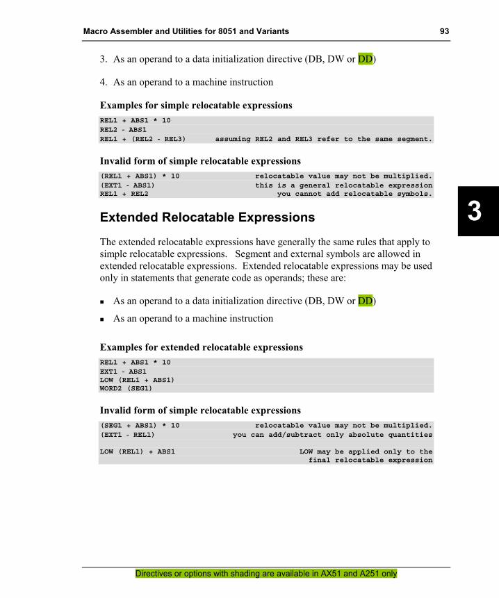
Macro Assembler and Utilities for 8051 and Variants 93
Directives or options with shading are available in AX51 and A251 only
3
3. As an operand to a data initialization directive (DB, DW or DD)
4. As an operand to a machine instruction
Examples for simple relocatable expressions REL1 + ABS1 * 10REL2 - ABS1REL1 + (REL2 - REL3) assuming REL2 and REL3 refer to the same segment.
Invalid form of simple relocatable expressions (REL1 + ABS1) * 10 relocatable value may not be multiplied.(EXT1 - ABS1) this is a general relocatable expressionREL1 + REL2 you cannot add relocatable symbols.
Extended Relocatable Expressions
The extended relocatable expressions have generally the same rules that apply to simple relocatable expressions. Segment and external symbols are allowed in extended relocatable expressions. Extended relocatable expressions may be used only in statements that generate code as operands; these are:
�� As an operand to a data initialization directive (DB, DW or DD)
�� As an operand to a machine instruction
Examples for extended relocatable expressions REL1 + ABS1 * 10EXT1 - ABS1LOW (REL1 + ABS1)WORD2 (SEG1)
Invalid form of simple relocatable expressions (SEG1 + ABS1) * 10 relocatable value may not be multiplied.(EXT1 - REL1) you can add/subtract only absolute quantities
LOW (REL1) + ABS1 LOW may be applied only to thefinal relocatable expression
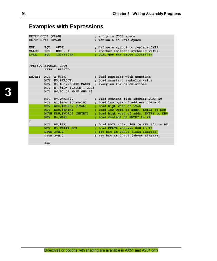
94 Chapter 3. Writing Assembly Programs
Directives or options with shading are available in AX51 and A251 only
3
Examples with Expressions EXTRN CODE (CLAB) ; entry in CODE spaceEXTRN DATA (DVAR) ; variable in DATA space
MSK EQU 0F0H ; define a symbol to replace 0xF0VALUE EQU MSK - 1 ; another constant symbolic valueLVAL EQU 12345678H ; LVAL get the value 12345678H
?PR?FOO SEGMENT CODERSEG ?PR?FOO
ENTRY: MOV A,#40H ; load register with constantMOV R5,#VALUE ; load constant symbolic valueMOV R3,#(0x20 AND MASK) ; examples for calculationsMOV R7,#LOW (VALUE + 20H)MOV R6,#1 OR (MSK SHL 4)
MOV R0,DVAR+20 ; load content from address DVAR+20MOV R1,#LOW (CLAB+10) ; load low byte of address CLAB+10MOV WR4,#WORD2 (LVAL) ; load high word of LVALMOV DR0,#ENTRY ; load low word of addr. ENTRY to DR0MOVH DR0,#WORD2 (ENTRY) ; load high word of addr. ENTRY to DR0MOV R4,@DR0 ; load content of ENTRY to R4
;MOV R5,80H ; load DATA addr. 80H (= SFR P0) to R5MOV R5,EDATA 80H ; load EDATA address 80H to R5SETB 30H.2 ; set bit at 30H.2 (long address)SETB 20H.2 ; set bit at 20H.2 (short address)
END

Macro Assembler and Utilities for 8051 and Variants 95
Directives or options with shading are available in AX51 and A251 only
4
Chapter 4. Assembler Directives This chapter describes the assembler directives. It shows how to define symbols and how to control the placement of code and data in program memory.
Introduction The Ax51 assembler has several directives that permit you to define symbol values, reserve and initialize storage, and control the placement of your code.
The directives should not be confused with instructions. They do not produce executable code, and with the exception of the DB, DW and DD directives, they have no direct effect on the contents of code memory. These directives change the state of the assembler, define user symbols, and add information to the object file.
The following table provides an overview of the assembler directives. Page refers to the page number in this user’s guide where you can find detailed information about the directive.
Directive / Page Format Description
BIT 109 symbol BIT bit_address Define a bit address in bit data space.
BSEG 106 BSEG [AT absolute address] Define an absolute segment within the bit address space.
CODE 109 symbol CODE code_address Assign a symbol name to a specific address in the code space.
CSEG 106 CSEG [AT absolute address] Define an absolute segment within the code address space.
DATA 109 symbol DATA data_address Assign a symbol name to a specific on-chip data address.
DB 113 [label:] DB expression [, expr ...] Generate a list of byte values.
DBIT 115 [label:] DBIT expression Reserve a space in bit units.
DD 114 [label:] DD expression [, expr ...] Generate a list of double word values.
DS 116 [label:] DS expression Reserve space in byte units.
DSB 117 [label:] DSB expression Reserve space in byte units.
DSD 119 [label:] DSD expression Reserve space in double word units.
DSEG 106 DSEG [AT absolute address] Define an absolute segment within the indirect internal data space.
DSW 118 [label:] DSW expression Reserve space in word units; advances the location counter of the current segment.

96 Chapter 4. Assembler Directives
Directives or options with shading are available in AX51 and A251 only
4
Directive / Page Format Description
DW 113 [label:] DW expression [, expr. ...] Generate a list of word values.
END 128 END Indicate end of program.
EQU 108 EQU expression Set symbol value permanently.
_ _ERROR_ _128 _ _ERROR_ _ text Generate a standard error message.
EVEN 126 EVEN Ensure word alignment for variables.
EXTRN 123 EXTERN
EXTRN class [:type] (symbol [, ...]) EXTERN class [:type] (symbol [, ...])
Defines symbols referenced in the current module that are defined in other modules.
IDATA 109 symbol IDATA idata_address Assign a symbol name to a specific indirect internal address.
ISEG 106 ISEG [AT absolute address] Define an absolute segment within the internal data space.
LABEL 121 name[:] LABEL [type] Assign a symbol name to a address location within a segment.
LIT 110 symbol LIT ’literal string’ Assign a symbol name to a string.
NAME 124 NAME modulname Specify the name of the current module.
ORG 125 ORG expression Set the location counter of the current segment.
PROC 120 ENDP
name PROC [type] name ENDP
Define a function start and end.
PUBLIC 122 PUBLIC symbol [, symbol ...] Identify symbols which can be used outside the current module.
RSEG 105 RSEG seg Select a relocatable segment.
SEGMENT 102 seg SEGMENT class [reloctype] [alloctype]
Define a relocatable segment.
SET 108 SET expression Set symbol value temporarily.
sfr, 110 sfr16 sbit
sfr symbol = address; sfr16 symbol = address; sbit symbol = address;
Define a special function register (SFR) symbol or a SFR bit symbol.
USING 126 USING expression Set the predefined symbolic register address and reserve space for the specified register bank.
XDATA 109 symbol XDATA xdata_address Assign a symbol name to a specific off-chip data address.
XSEG 106 XSEG [AT absolute address] Define an absolute segment within the external data address space.

Macro Assembler and Utilities for 8051 and Variants 97
Directives or options with shading are available in AX51 and A251 only
4
The directives are divided into the following categories:
�� Segment Control Generic Segments: SEGMENT, RSEG Absolute Segments: CSEG, DSEG, BSEG, ISEG, XSEG
�� Symbol Definition Generic Symbols: EQU, SET Address Symbols: BIT, CODE, DATA, IDATA, XDATA SFR Symbols: sfr, sfr16, sbit Text Replacement: LIT
�� Memory Initialization DB, DW, DD
�� Memory Reservation DBIT, DS, DSB, DSW, DSD
�� Procedure Declaration PROC / ENDP, LABEL
�� Program Linkage PUBLIC, EXTRN / EXTERN, NAME
�� Address Control ORG, EVEN, USING
�� Others END, _ _ERROR_ _
The Ax51 assembler is a multi-pass assembler. In the first pass, symbol values are determined. In the subsequent passes, forward references are resolved and object code is produced. This structure imposes a restriction on the source program: expressions which define symbol values (refer to “Symbol Definition” on page 108) and expressions which control the location counter (refer to “ORG” on page 125, “DS” on page 116, and “DBIT” on page 115) may not have forward references.

98 Chapter 4. Assembler Directives
Directives or options with shading are available in AX51 and A251 only
4
Segment Directives A segment is a block of code or data memory the assembler creates from code or data in an x51 assembly source file. How you use segments in your source modules depends on the complexity of your application. Smaller applications need less memory and are typically less complex than large multi–module applications.
The x51 CPU has several specific memory areas. You use segments to locate program code, constant data, and variables in these areas.
Location Counter Ax51 maintains a location counter for each segment. The location counter is a pointer to the address space of the active segment. It represents an offset for generic segments or the actual address for absolute segments. When a segment is first activated, the location counter is set to 0. The location counter is changed after each instruction by the length of the instruction. The memory initialization and reservation directives (i.e. DS, DB or DBIT) change the value of the location counter as memory is allocated by these directives. The ORG directive sets a new value for the location counter. If you change the active segment and later return to that segment, the location counter is restored to its previous value. Whenever the assembler encounters a label, it assigns the current value of the location counter and the type of the current segment to that label.
The dollar sign ($) indicates the value of the location counter in the active segment. When you use the $ symbol, keep in mind that its value changes with each instruction, but only after that instruction has been completely evaluated. If you use $ in an operand to an instruction or directive, it represents the address of the first byte of that instruction.
The following sections describe the different types of segments.
Generic Segments Generic segments have a name and a class as well as other attributes. Generic segments with the same name but from different object modules are considered to be parts of the same segment and are called partial segments. These segments are combined at link time by the linker/locator.

Macro Assembler and Utilities for 8051 and Variants 99
Directives or options with shading are available in AX51 and A251 only
4
Generic segments are created using the SEGMENT directive. You must specify the name of the segment, the segment class, and an optional relocation type and alignment type when you create a relocatable segment.
Example MYPROG SEGMENT CODE
defines a segment named MYPROG with a memory class of CODE. This means that data in the MYPROG segment will be located in the code or program area of the x51. Refer to “SEGMENT” on page 102 for more information on how to declare generic segments.
Once you have defined a relocatable segment name, you must select that segment using the RSEG directive. When RSEG is used to select a segment, that segment becomes the active segment that Ax51 uses for subsequent code and data until the segment is changed with RSEG or with an absolute segment directive.
Example RSEG MYPROG
will select the MYPROG segment that is defined above.
Typically, assembly routines are placed in generic segments. If you interface your assembly routines to C, all of your assembly routines must reside in separate generic segments and the segment names must follow the standards used by Cx51. Refer to the Compiler User’s Guide for more information on interfacing assembler programs to C.

100 Chapter 4. Assembler Directives
Directives or options with shading are available in AX51 and A251 only
4
Stack Segment The x51 architecture uses a hardware stack to store return addresses for CALL instructions and also for temporary storage using the PUSH and POP instructions. An 8051 application that uses these instructions must setup the stack pointer to an area of memory that will not be used by other variables.
For the classic 8051 a stack segment must be defined and space must be reserved as follows. This definition also works for the extended 8051 and the 251, however these controllers typically support stack also in other areas.
STACK SEGMENT IDATARSEG STACK ; select the stack segmentDS 10h ; reserve 16 bytes of space
Then, you must initialize the stack pointer early in your program.
CSEG AT 0 ; RESET VectorJMP STARTUP ; Jump to startup code
STARTUP: ; code executed at RESETMOV SP,#STACK - 1 ; load Stack Pointer
For the Philips 80C51MX or the Intel/Temic 251 a stack segment may be defined and space must be reserved as follows.
STACK SEGMENT EDATARSEG STACK ; select the stack segmentDS 100h ; reserve 256 bytes of space
Then, you must initialize the stack pointer early in your program.
CSEG AT 0 ; RESET VectorJMP STARTUP ; Jump to startup code
STARTUP: ; code executed at RESET; Stack setup for Philips 80C51MX
ORL MXCON,#0x02 ; enable extended stackMOV SPE,#HIGH (STACK - 1) ; load Stack highMOV SP,#LOW (STACK - 1) ; load Stack low
; for Intel/Temic 251MOV DR60,#STACK - 1 ; load Stack Pointer
If you are interfacing assembly routines to C, you probably do not need to setup the stack. This is already done for you in the C startup code.

Macro Assembler and Utilities for 8051 and Variants 101
Directives or options with shading are available in AX51 and A251 only
4
Absolute Segments Absolute segments reside in a fixed memory location. Absolute segments are created using the CSEG, DSEG, XSEG, ISEG, and BSEG directives. These directives allow you to locate code and data or reserve memory space in a fixed location. You use absolute segments when you need to access a fixed memory location or when you want to place program code or constant data at a fixed memory address. Refer to the CSEG, DSEG, ISEG, XSEG, ISEG directives for more information on how to declare absolute segments.
After reset, the 8051 variants begin program executing at CODE address 0. The Intel/Temic 251 starts execution at address FF0000. Some type of program code must reside at this address. You can use an absolute segment to force program code into this address. The following example is used in the Cx51 startup routines to branch from the reset address to the beginning of the initialization code.
.
.
.CSEG AT 0
RESET_VEC: LJMP STARTUP...
The program code that we place at address 0000h (for 251 at address FF0000h) with the CSEG AT 0 directive performs a jump to the STARTUP label.
AX51 and A251 supports absolute segment controls for compatibility to A51. AX51 and A251 translates the CSEG, DSEG, XSEG, ISEG and BSEG directives to a generic segment directive.
Default Segment By default, Ax51 assumes that the CODE segment is selected and initializes the location counter to 0000h (FF0000h) when it begins processing an assembly source module. This allows you to create programs without specifying any relocatable or absolute segment directives.
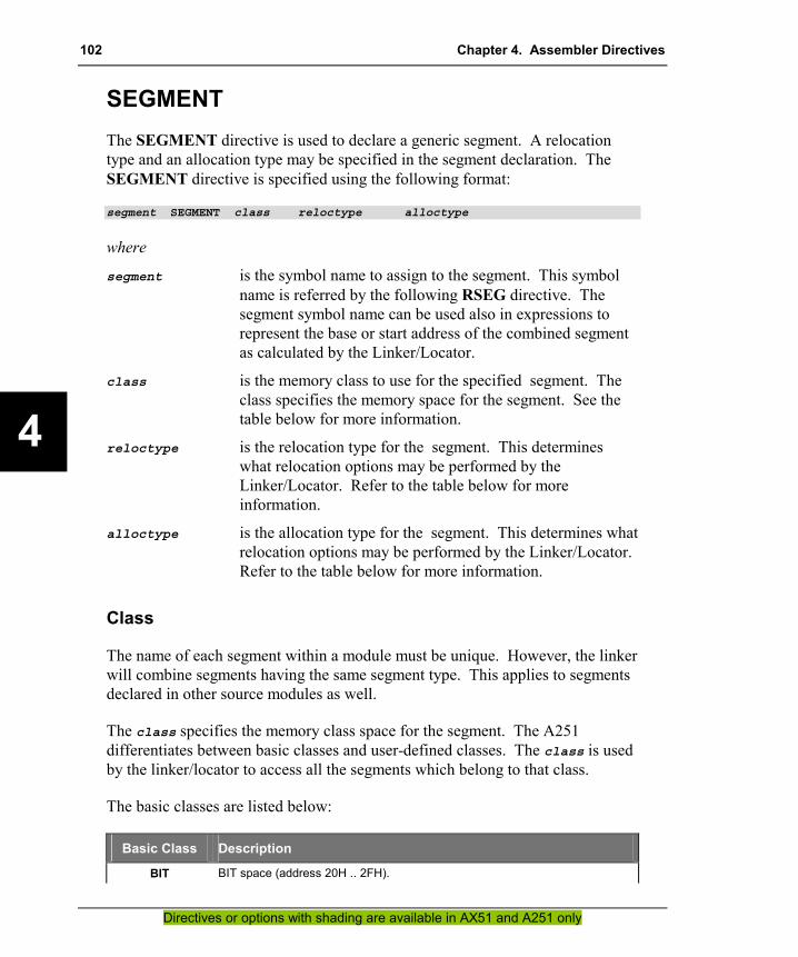
102 Chapter 4. Assembler Directives
Directives or options with shading are available in AX51 and A251 only
4
SEGMENT The SEGMENT directive is used to declare a generic segment. A relocation type and an allocation type may be specified in the segment declaration. The SEGMENT directive is specified using the following format:
segment SEGMENT class reloctype alloctype
where
segment is the symbol name to assign to the segment. This symbol name is referred by the following RSEG directive. The segment symbol name can be used also in expressions to represent the base or start address of the combined segment as calculated by the Linker/Locator.
class is the memory class to use for the specified segment. The class specifies the memory space for the segment. See the table below for more information.
reloctype is the relocation type for the segment. This determines what relocation options may be performed by the Linker/Locator. Refer to the table below for more information.
alloctype is the allocation type for the segment. This determines what relocation options may be performed by the Linker/Locator. Refer to the table below for more information.
Class
The name of each segment within a module must be unique. However, the linker will combine segments having the same segment type. This applies to segments declared in other source modules as well.
The class specifies the memory class space for the segment. The A251 differentiates between basic classes and user-defined classes. The class is used by the linker/locator to access all the segments which belong to that class.
The basic classes are listed below:
Basic Class Description
BIT BIT space (address 20H .. 2FH).
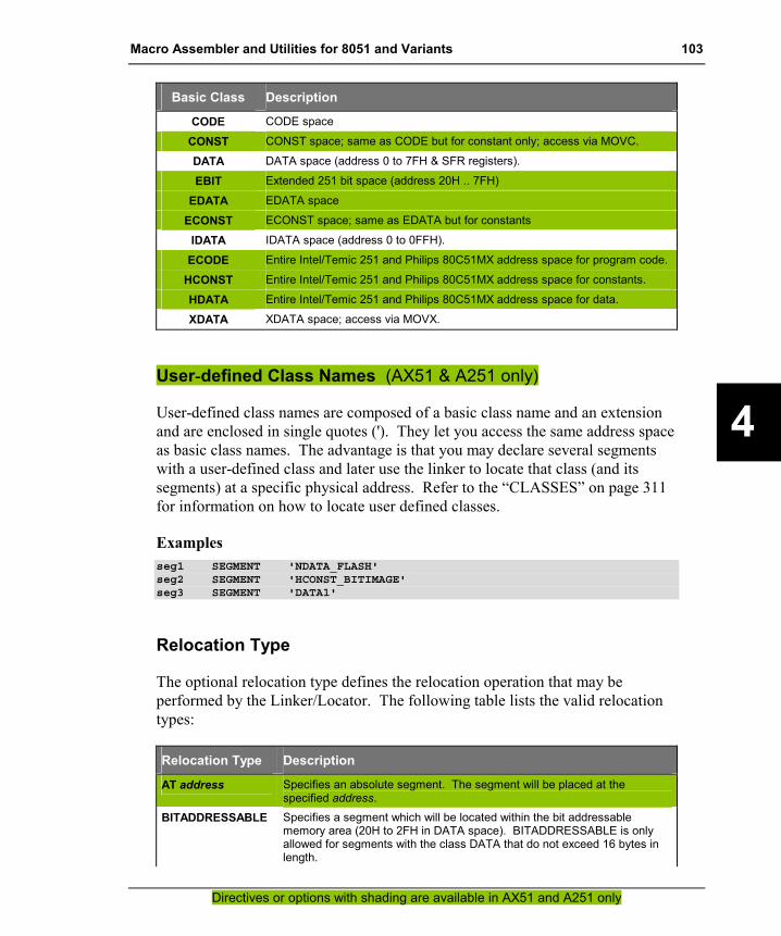
Macro Assembler and Utilities for 8051 and Variants 103
Directives or options with shading are available in AX51 and A251 only
4
Basic Class Description
CODE CODE space
CONST CONST space; same as CODE but for constant only; access via MOVC.
DATA DATA space (address 0 to 7FH & SFR registers).
EBIT Extended 251 bit space (address 20H .. 7FH)
EDATA EDATA space
ECONST ECONST space; same as EDATA but for constants
IDATA IDATA space (address 0 to 0FFH).
ECODE Entire Intel/Temic 251 and Philips 80C51MX address space for program code.
HCONST Entire Intel/Temic 251 and Philips 80C51MX address space for constants.
HDATA Entire Intel/Temic 251 and Philips 80C51MX address space for data.
XDATA XDATA space; access via MOVX.
User-defined Class Names (AX51 & A251 only)
User-defined class names are composed of a basic class name and an extension and are enclosed in single quotes ('). They let you access the same address space as basic class names. The advantage is that you may declare several segments with a user-defined class and later use the linker to locate that class (and its segments) at a specific physical address. Refer to the “CLASSES” on page 311 for information on how to locate user defined classes.
Examples seg1 SEGMENT 'NDATA_FLASH'seg2 SEGMENT 'HCONST_BITIMAGE'seg3 SEGMENT 'DATA1'
Relocation Type
The optional relocation type defines the relocation operation that may be performed by the Linker/Locator. The following table lists the valid relocation types:
Relocation Type Description
AT address Specifies an absolute segment. The segment will be placed at the specified address.
BITADDRESSABLE Specifies a segment which will be located within the bit addressable memory area (20H to 2FH in DATA space). BITADDRESSABLE is only allowed for segments with the class DATA that do not exceed 16 bytes in length.
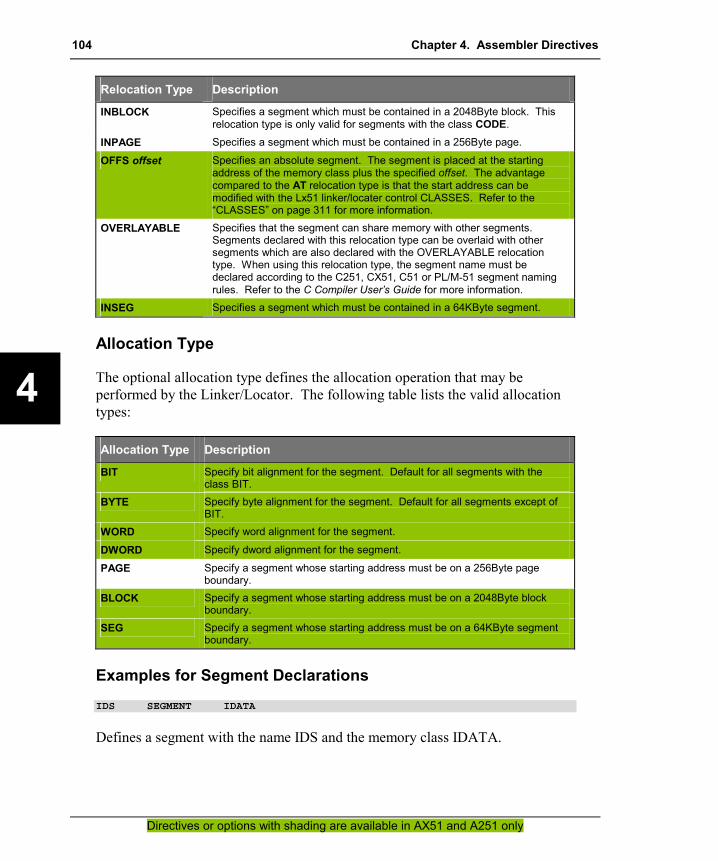
104 Chapter 4. Assembler Directives
Directives or options with shading are available in AX51 and A251 only
4
Relocation Type Description
INBLOCK Specifies a segment which must be contained in a 2048Byte block. This relocation type is only valid for segments with the class CODE.
INPAGE Specifies a segment which must be contained in a 256Byte page.
OFFS offset Specifies an absolute segment. The segment is placed at the starting address of the memory class plus the specified offset. The advantage compared to the AT relocation type is that the start address can be modified with the Lx51 linker/locater control CLASSES. Refer to the “CLASSES” on page 311 for more information.
OVERLAYABLE Specifies that the segment can share memory with other segments. Segments declared with this relocation type can be overlaid with other segments which are also declared with the OVERLAYABLE relocation type. When using this relocation type, the segment name must be declared according to the C251, CX51, C51 or PL/M-51 segment naming rules. Refer to the C Compiler User’s Guide for more information.
INSEG Specifies a segment which must be contained in a 64KByte segment.
Allocation Type
The optional allocation type defines the allocation operation that may be performed by the Linker/Locator. The following table lists the valid allocation types:
Allocation Type Description
BIT Specify bit alignment for the segment. Default for all segments with the class BIT.
BYTE Specify byte alignment for the segment. Default for all segments except of BIT.
WORD Specify word alignment for the segment.
DWORD Specify dword alignment for the segment.
PAGE Specify a segment whose starting address must be on a 256Byte page boundary.
BLOCK Specify a segment whose starting address must be on a 2048Byte block boundary.
SEG Specify a segment whose starting address must be on a 64KByte segment boundary.
Examples for Segment Declarations IDS SEGMENT IDATA
Defines a segment with the name IDS and the memory class IDATA.
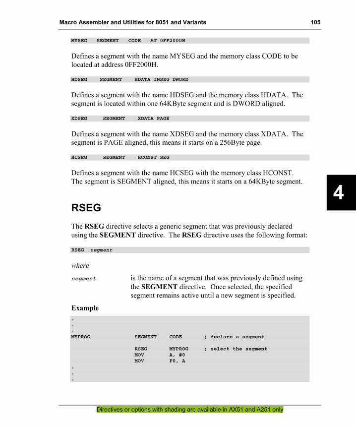
Macro Assembler and Utilities for 8051 and Variants 105
Directives or options with shading are available in AX51 and A251 only
4
MYSEG SEGMENT CODE AT 0FF2000H
Defines a segment with the name MYSEG and the memory class CODE to be located at address 0FF2000H.
HDSEG SEGMENT HDATA INSEG DWORD
Defines a segment with the name HDSEG and the memory class HDATA. The segment is located within one 64KByte segment and is DWORD aligned.
XDSEG SEGMENT XDATA PAGE
Defines a segment with the name XDSEG and the memory class XDATA. The segment is PAGE aligned, this means it starts on a 256Byte page.
HCSEG SEGMENT HCONST SEG
Defines a segment with the name HCSEG with the memory class HCONST. The segment is SEGMENT aligned, this means it starts on a 64KByte segment.
RSEG The RSEG directive selects a generic segment that was previously declared using the SEGMENT directive. The RSEG directive uses the following format:
RSEG segment
where
segment is the name of a segment that was previously defined using the SEGMENT directive. Once selected, the specified segment remains active until a new segment is specified.
Example ...MYPROG SEGMENT CODE ; declare a segment
RSEG MYPROG ; select the segmentMOV A, #0MOV P0, A
.
.
.

106 Chapter 4. Assembler Directives
Directives or options with shading are available in AX51 and A251 only
4
BSEG, CSEG, DSEG, ISEG, XSEG The BSEG, CSEG, DSEG, ISEG, XSEG directives select an absolute segment. This directives use the following formats:
BSEG AT address defines an absolute BIT segment.CSEG AT address defines an absolute CODE segment.DSEG AT address defines an absolute DATA segment.ISEG AT address defines an absolute IDATA segment.XSEG AT address defines an absolute XDATA segment.
where
address is an optional absolute base address at which the segment begins. The address may not contain any forward references and must be an expression that can be evaluated to a valid address.
CSEG, DSEG, ISEG, BSEG and XSEG select an absolute segment within the code, internal data, indirect internal data, bit, or external data address spaces. If you choose to specify an absolute address (by including AT address), the assembler terminates the last absolute segment, if any, of the specified segment type, and creates a new absolute segment starting at that address. If you do not specify an address, the last absolute segment of the specified type is continued. If no absolute segment of this type was selected and the absolute address is omitted, a new segment is created starting at location 0. You cannot use any forward references and the start address must be an absolute expression.
The AX51 and A251 Macro Assembler supports the BSEG, CSEG, DSEG, ISEG, and XSEG directives for A51 compatibility.

Macro Assembler and Utilities for 8051 and Variants 107
Directives or options with shading are available in AX51 and A251 only
4
These directives are converted to standard segments as follows:
A51 Directive Converted to AX51/A251 Segment Declaration
BSEG AT 20H.1 ?BI?modulename?n SEGMENT OFFS 20H.1 CSEG AT 1234H ?CO?modulename?n SEGMENT OFFS 1234H DSEG AT 40H ?DT?modulename?n SEGMENT OFFS 40H ISEG AT 80H ?ID?modulename?n SEGMENT OFFS 80H XSEG AT 5100H ?XD?modulename?n SEGMENT OFFS 5100H
where
modulname is the name of the current assembler module
n is a sequential number incremented for every absolute segment.
Examples BSEG AT 30h ; absolute bit segment @ 30h
DEC_FLAG: DBIT 1 ; absolute bitINC_FLAG: DBIT 1
CSEG AT 100h ; absolute code segment @ 100hPARITY_TAB: DB 00h ; parity for 00h
DB 01h ; 01hDB 01h ; 02hDB 00h ; 03h
.
.
.DB 01h ; FEhDB 00h ; FFhDSEG AT 40h ; absolute data segment @ 40h
TMP_A: DS 2 ; absolute data wordTMP_B: DS 4
ISEG AT 40h ; abs indirect data seg @ 40hTMP_IA: DS 2TMP_IB: DS 4
XSEG AT 1000h ; abs external data seg @ 1000hOEMNAME: DS 25 ; abs external dataPRDNAME: DS 25VERSION: DS 25

108 Chapter 4. Assembler Directives
Directives or options with shading are available in AX51 and A251 only
4
Symbol Definition The symbol definition directives allow you to create symbols that can be used to represent registers, numbers, and addresses.
Symbols defined by these directives may not have been previously defined and may not be redefined by any means. The SET directive is the only exception to this.
EQU, SET The EQU and SET directive assigns a numeric value or register symbol to the specified symbol name. Symbols defined with EQU may not have been previously defined and may not be redefined by any means. The SET directive allows later redefinition of symbols. Statements involving the EQU or SET directive are formatted as follows:
symbol EQU expressionsymbol EQU registersymbol SET expressionsymbol SET register
where
symbol is the name of the symbol to define. The expression or register specified in the EQU or SET directive will be substituted for each occurrence of symbol that is used in your assembly program.
expression is a numeric expression which contains no forward references, or a simple relocatable expression.
register is one of the following register names: A, R0, R1, R2, R3, R4, R5, R6, or R7.
Symbols defined with the EQU or SET directive may be used anywhere in operands, expressions, or addresses. Symbols that are defined as a register name can be used anywhere a register is allowed. A251 replaces each occurrence of the defined symbol in your assembly program with the specified numeric value or register symbol.
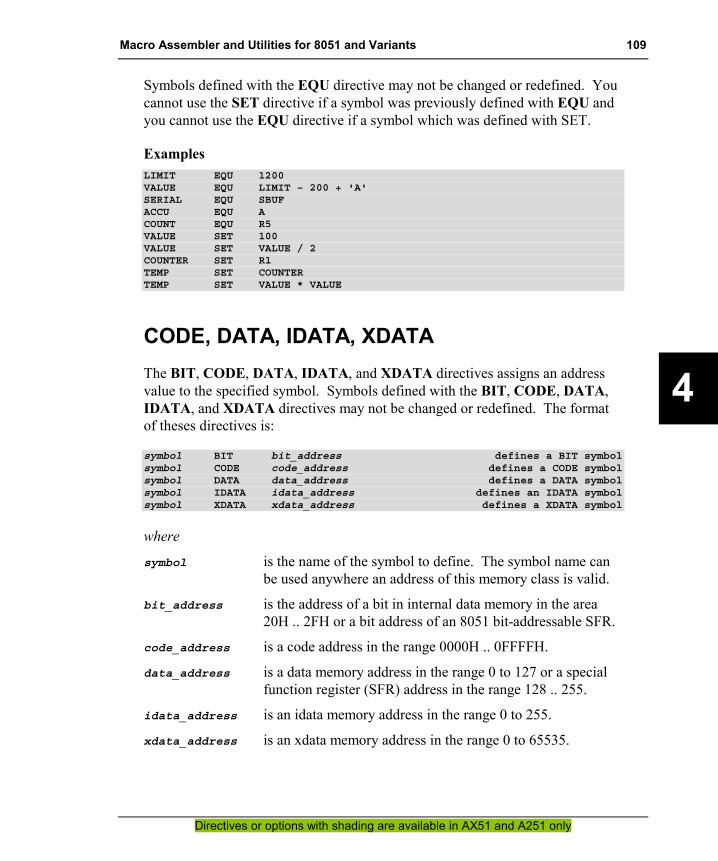
Macro Assembler and Utilities for 8051 and Variants 109
Directives or options with shading are available in AX51 and A251 only
4
Symbols defined with the EQU directive may not be changed or redefined. You cannot use the SET directive if a symbol was previously defined with EQU and you cannot use the EQU directive if a symbol which was defined with SET.
Examples LIMIT EQU 1200VALUE EQU LIMIT – 200 + 'A'SERIAL EQU SBUFACCU EQU ACOUNT EQU R5VALUE SET 100VALUE SET VALUE / 2COUNTER SET R1TEMP SET COUNTERTEMP SET VALUE * VALUE
CODE, DATA, IDATA, XDATA The BIT, CODE, DATA, IDATA, and XDATA directives assigns an address value to the specified symbol. Symbols defined with the BIT, CODE, DATA, IDATA, and XDATA directives may not be changed or redefined. The format of theses directives is:
symbol BIT bit_address defines a BIT symbolsymbol CODE code_address defines a CODE symbolsymbol DATA data_address defines a DATA symbolsymbol IDATA idata_address defines an IDATA symbolsymbol XDATA xdata_address defines a XDATA symbol
where
symbol is the name of the symbol to define. The symbol name can be used anywhere an address of this memory class is valid.
bit_address is the address of a bit in internal data memory in the area 20H .. 2FH or a bit address of an 8051 bit-addressable SFR.
code_address is a code address in the range 0000H .. 0FFFFH.
data_address is a data memory address in the range 0 to 127 or a special function register (SFR) address in the range 128 .. 255.
idata_address is an idata memory address in the range 0 to 255.
xdata_address is an xdata memory address in the range 0 to 65535.

110 Chapter 4. Assembler Directives
Directives or options with shading are available in AX51 and A251 only
4
Example DATA_SEG SEGMENT BITADDRESSABLERSEG DATA_SEG ; a bitaddressable rel_seg
CTRL: DS 1 ; a 1–byte variable (CTRL)ALARM BIT CTRL.0 ; bit in a relocatable byteSHUT BIT ALARM+1 ; the next bitENABLE_FLAG BIT 60H ; an absolute bitDONE_FLAG BIT 24H.2 ; an absolute bitP1_BIT2 EQU 90H.2 ; a SFR bitRESTART CODE 00HINTVEC_0 CODE RESTART + 3INTVEC_1 CODE RESTART + 0BHINTVEC_2 CODE RESTART + 1BHSERBUF DATA SBUF ; redfinition of the SFR SBUFRESULT DATA 40HRESULT2 DATA RESULT + 2PORT1 DATA 90H ; a SFR symbolBUFFER IDATA 60HBUF_LEN EQU 20HBUF_END IDATA BUFFER + BUF_LEN – 1XSEG1 SEGMENT XDATARSEG XSEG1
DTIM: DS 6 ;reserve 6–bytes for DTIMTIME XDATA DTIM + 0DATE XDATA DTIM + 3
esfr, sfr, sfr16, sbit The sfr, sfr16 and sbit directives are fully compatible to the Cx51 compiler and allows you to use a generic SFR register definition file for both: the Ax51 macro assembler and the Cx51 compiler. The esfr directive defines symbols in the extended SFR space of the Philips 80C51MX architecture. This directive is only available in the AX51 macro assembler. These directives have the following format:
sfr sfr_symbol = address;esfr sfr_symbol = address;sfr16 sfr_symbol = address; ; ignored by Ax51sbit sfr_symbol = bit-address;
where
sfr_symbol is the name of the special function register (SFR) symbol to define.
address is an SFR address in the range 0x80 – 0xFF.
bit-address is address of an SFR bit in the format address ^ bitpos or sfr_symbol ^ bitpos. address or sfr_symbol refers to an bit-

Macro Assembler and Utilities for 8051 and Variants 111
Directives or options with shading are available in AX51 and A251 only
4
addressable SFR and bitpos specifies the bit position of the SFR bit in the range 0 – 7.
Symbols defined with the esfr, sfr, or sbit directive may be used anywhere as address of a SFR or SFR bit.
Example sfr P0 = 0x80;sfr P1 = 0x90;sbit P0_0 = P0^0;sbit P1_1 = 0x90^1;esfr MXCON = 0xFF; /* extended Philips 80C51MX SFR */sfr16 T2 = 0xCC; /* ingnored by Ax51 */
NOTE The Ax51 assembler ignores symbol definitions that start with sfr16. This is implemented for compatibility to the Cx51 compiler.
LIT (AX51 & A251 only) The LIT directive provides a simple text substitution facility. The LIT directive has the following format:
symbol LIT 'literal string'symbol LIT "literal string"
where
symbol is the name of the symbol to define. The literal string specified in the LIT directive will be substituted for each occurrence of symbol that is used in your assembly program.
literal string is a numeric expression which contains no forward references, or a simple relocatable expression.
Every time the symbol is encountered, it is replaced by the literal string assigned to the symbol name. The symbol name follows the same rules as other identifiers, that is, a literal name is not encountered if it does not form a separate token. If a substring is to be replaced, symbol must be enclosed in braces: TEXT{symbol}. The assembler listing shows the expanded lines where literals are substituted.

112 Chapter 4. Assembler Directives
Directives or options with shading are available in AX51 and A251 only
4
Example
Source text containing literals before assembly:
$INCLUDE (REG51.INC)
REG1 LIT 'R1'NUM LIT 'A1'DBYTE LIT "DATA BYTE"FLAG LIT 'ACC.3'
?PR?MOD SEGMENT CODERSEG ?PR?MOD
MOV REG1,#5SETB FLAGJB FLAG,LAB_{NUM}PUSH DBYTE 0
LAB_{NUM}:
END
Assembler listing from previous example:
1 $INCLUDE (REG51.INC)+1 80 +1 $RESTORE
8182 REG1 LIT 'R1'83 NUM LIT 'A1'84 DBYTE LIT "DATA BYTE"85 FLAG LIT 'ACC.3'86
------ 87 ?PR?MOD SEGMENT CODE------ 88 RSEG ?PR?MOD
89000000 7E1005 90 MOV R1,#5000003 D2E3 91 SETB ACC.3000005 20E300 F 92 JB ACC.3,LAB_A1000008 C000 93 PUSH DATA BYTE 000000A 94 LAB_A1:
9596 END

Macro Assembler and Utilities for 8051 and Variants 113
Directives or options with shading are available in AX51 and A251 only
4
Memory Initialization The memory initialization directives are used to initialize code or constant space in either word, double-word, or byte units. The memory image starts at the point indicated by the current value of the location counter in the currently active segment.
DB The DB directive initializes code memory with 8-bit byte values. The DB directive has the following format:
label: DB expression , expression …
where
label is the symbol that is given the address of the initialized memory.
expression is a byte value. Each expression may be a symbol, a character string, or an expression.
The DB directive can only be specified within a code or const segment. If the DB directive is used in a different segment, Ax51 will generate an error message.
Example REQUEST: DB 'PRESS ANY KEY TO CONTINUE', 0TABLE: DB 0,1,8,'A','0', LOW(TABLE),';'ZERO: DB 0, ''''CASE_TAB: DB LOW(REQUEST), LOW(TABLE), LOW(ZERO)
DW The DW directive initializes code memory with 16-bit word values. The DW directive has the following format:
label: DW expression , expression …

114 Chapter 4. Assembler Directives
Directives or options with shading are available in AX51 and A251 only
4
where
label is the symbol that is given the address of the initialized memory.
expression is the initialization data. Each expression may contain a symbol, a character string, or an expression.
The DW directive can only be specified within a code or const segment. If the DW directive is used in a different segment, Ax51 will generate an error message.
Example TABLE: DW TABLE, TABLE + 10, ZEROZERO: DW 0CASE_TAB: DW CASE0, CASE1, CASE2, CASE3, CASE4
DW $
DD (AX51 & A251 only) The DD directive initializes code memory with 32–bit double word values. The DD directive has the following format:
label: DD expression , expression …
where
label is the symbol that is given the address of the initialized memory and
expression is the initialization data. Each expression may contain a symbol, a character string, or an expression.
The DD directive can only be specified within a code or const segment. If the DD directive is used in a different segment, Ax51 will generate an error message.
Example TABLE: DD TABLE, TABLE + 10, ZERO
DD $ZERO: DD 0LONG_VAL: DD 12345678H, 0FFFFFFFFH, 1

Macro Assembler and Utilities for 8051 and Variants 115
Directives or options with shading are available in AX51 and A251 only
4
Reserving Memory The memory reservation directives are used to reserve space in either word, dword, byte, or bit units. The space reserved starts at the point indicated by the current value of the location counter in the currently active segment.
DBIT The DBIT directive reserves space in a bit or ebit segment. The DBIT directive has the following format:
label: DBIT expression
where
label is the symbol that is given the address of the reserved memory. The label is a symbol of the type BIT and gets the current address value and the memory class of the active segment. The label can only be used where a symbol of this type is allowed.
expression is the number of bits to reserve. The expression cannot contain forward references, relocatable symbols, or external symbols.
The DBIT directive reserves space in the bit segment starting at the current address. The location counter for the bit segment is increased by the value of the expression. You should note that the location counter for the bit segment references bits and not bytes.
NOTE The Ax51 assembler is a two–pass assembler. Symbols are collected and the length of each instruction is determined in the first pass. In the second pass, forward references are resolved and object code is produced. For these reasons, an expression used with the DBIT directive may not contain forward references.
Example ON_FLAG: DBIT 1 ; reserve 1 bitOFF_FLAG: DBIT 1

116 Chapter 4. Assembler Directives
Directives or options with shading are available in AX51 and A251 only
4
DS The DS directive reserves a specified number of bytes in a memory space. The DS directive has the following format:
label: DS expression
where
label is the symbol that is given the address of the reserved memory. The label is a typeless number and gets the current address value and the memory class of the active segment. The label can only be used where a symbol of this type is allowed.
expression is the number of bytes to reserve. The expression cannot contain forward references, relocatable symbols, or external symbols.
The DS directive reserves space in the current segment at the current address. The current address is then increased by the value of the expression. The sum of the location counter and the value of the specified expression should not exceed the limitations of the current address space.
NOTE The A251 assembler is a two–pass assembler. Symbols are collected and the length of each instruction is determined in the first pass. In the second pass, forward references are resolved and object code is produced. For these reasons, an expression used with the DS directive may not contain forward references.
Example GAP: DS (($ + 16) AND 0FFF0H) – $
DS 20TIME: DS 8

Macro Assembler and Utilities for 8051 and Variants 117
Directives or options with shading are available in AX51 and A251 only
4
DSB (AX51 & A251 only) The DSB directive reserves a specified number of bytes in a memory space. The DSB directive has the following format:
label: DSB expression
where
label is the symbol that is given the address of the reserved memory. The label is a symbol of the type BYTE and gets the current address value and the memory class of the active segment. The label can only be used where a symbol of this type is allowed.
expression is the number of bytes to reserve. The expression cannot contain forward references, relocatable symbols, or external symbols.
The DSB directive reserves space in the current segment at the current address. The current address is then increased by the value of the expression. The sum of the location counter and the value of the specified expression should not exceed the limitations of the current address space.
NOTE The Ax51 assembler is a two–pass assembler. Symbols are collected and the length of each instruction is determined in the first pass. In the second pass, forward references are resolved and object code is produced. For these reasons, an expression used with the DSB directive may not contain forward references.
Example
DAY: DSB 1MONTH: DSB 1HOUR: DSB 1MIN: DSB 1

118 Chapter 4. Assembler Directives
Directives or options with shading are available in AX51 and A251 only
4
DSW (AX51 & A251 only) The DSW directive reserves a specified number of words in a memory space. The DSW directive has the following format:
label: DSW expression
where
label is the symbol that is given the address of the reserved memory. The label is a symbol of the type WORD and gets the current address value and the memory class of the active segment. The label can only be used where a symbol of this type is allowed.
expression is the number of bytes to reserve. The expression cannot contain forward references, relocatable symbols, or external symbols.
The DSW directive reserves space in the current segment at the current address. The current address is then increased by the value of the expression. The sum of the location counter and the value of the specified expression should not exceed the limitations of the current address space.
NOTE The Ax51 assembler is a two–pass assembler. Symbols are collected and the length of each instruction is determined in the first pass. In the second pass, forward references are resolved and object code is produced. For these reasons, an expression used with the DSW directive may not contain forward references.
Example YEAR: DSW 1DAYinYEAR: DSW 1

Macro Assembler and Utilities for 8051 and Variants 119
Directives or options with shading are available in AX51 and A251 only
4
DSD (AX51 & A251 only) The DSD directive reserves a specified number of double words in a memory space. The DSD directive has the following format:
label: DSD expression
where
label is the symbol that is given the address of the reserved memory. The label is a symbol of the type DWORD and gets the current address value and the memory class of the active segment. The label can only be used where a symbol of this type is allowed.
expression is the number of bytes to reserve. The expression cannot contain forward references, relocatable symbols, or external symbols.
The DSD directive reserves space in the current segment at the current address. The current address is then increased by the value of the expression. The sum of the location counter and the value of the specified expression should not exceed the limitations of the current address space.
NOTE The Ax51 assembler is a two–pass assembler. Symbols are collected and the length of each instruction is determined in the first pass. In the second pass, forward references are resolved and object code is produced. For these reasons, an expression used with the DSD directive may not contain forward references.
Example SEC_CNT: DSD 1LONG_ARR: DSD 50

120 Chapter 4. Assembler Directives
Directives or options with shading are available in AX51 and A251 only
4
Procedure Declaration (AX51 & A251 only) Ax51 provides procedures to implement the concept of subroutines. Procedures can be executed in-line (control “falls through” to them), jumped to, or invoked by a CALL. Calls are recommended as a better programming practice.
PROC / ENDP (AX51 & A251 only) The PROC and ENDP directives are used to define a label for a sequence of machine instructions called a procedure. For the Philips 80C51MX and Intel/Temic 251 architecture a procedure may have either the type NEAR or FAR. Depending on the type it is called with LCALL or ACALL (for NEAR) or ECALL (for FAR). Unlike C functions, assembler procedures do not provide local scopes for labels. Identifiers must be unique in A251 because the visibility is module wide. The format of the PROC/ENDP directives is:
name PROC [ type ]; procedure text
::
RETname ENDP
where
name is the name of the procedure.
type specifies the type of the procedure, and must be one of the following:
Type Description
none The type defaults to NEAR
NEAR Defines a near procedure; called with LCALL or ACALL. FAR Defines a far procedure; called with ECALL.
You should specify FAR if the procedure is called from a different 64KByte segment. A procedure normally ends with a RET instruction. The software instruction RET will automatically be converted to an appropriate machine return instruction. For example:
RET Return from a near procedure.
ERET Return from a far procedure.
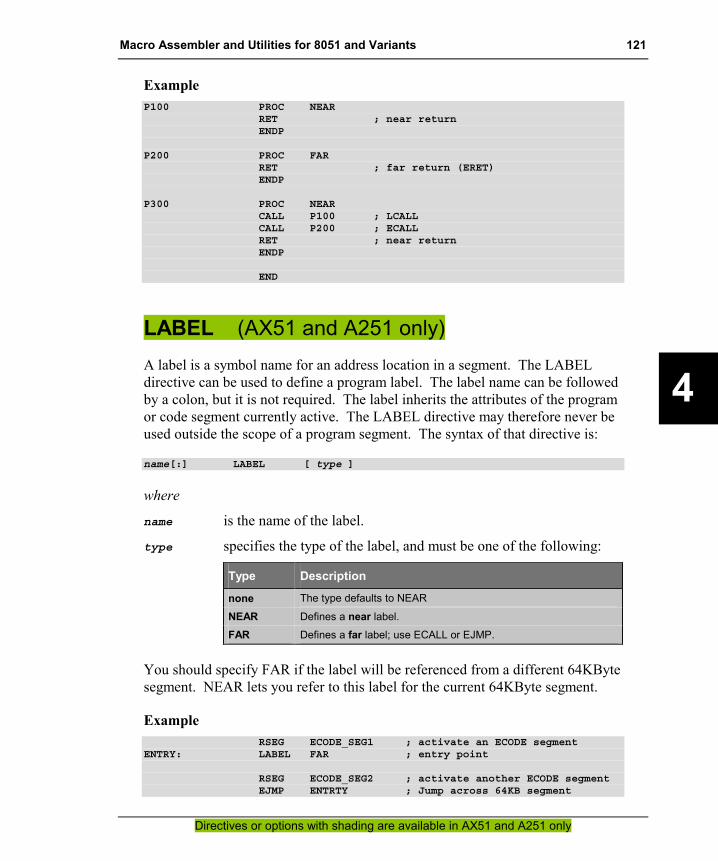
Macro Assembler and Utilities for 8051 and Variants 121
Directives or options with shading are available in AX51 and A251 only
4
Example P100 PROC NEAR
RET ; near returnENDP
P200 PROC FARRET ; far return (ERET)ENDP
P300 PROC NEARCALL P100 ; LCALLCALL P200 ; ECALLRET ; near returnENDP
END
LABEL (AX51 and A251 only) A label is a symbol name for an address location in a segment. The LABEL directive can be used to define a program label. The label name can be followed by a colon, but it is not required. The label inherits the attributes of the program or code segment currently active. The LABEL directive may therefore never be used outside the scope of a program segment. The syntax of that directive is:
name[:] LABEL [ type ]
where
name is the name of the label.
type specifies the type of the label, and must be one of the following:
Type Description
none The type defaults to NEAR
NEAR Defines a near label. FAR Defines a far label; use ECALL or EJMP.
You should specify FAR if the label will be referenced from a different 64KByte segment. NEAR lets you refer to this label for the current 64KByte segment.
Example RSEG ECODE_SEG1 ; activate an ECODE segment
ENTRY: LABEL FAR ; entry point
RSEG ECODE_SEG2 ; activate another ECODE segmentEJMP ENTRTY ; Jump across 64KB segment

122 Chapter 4. Assembler Directives
Directives or options with shading are available in AX51 and A251 only
4
Program Linkage Program linkage directives allow the separately assembled modules to communicate by permitting inter-module references and the naming of modules.
PUBLIC The PUBLIC directive lists symbols that may be used in other object modules. The PUBLIC directive makes the specified symbols available in the generated object module. This, in effect, publicizes the names of these symbols. The PUBLIC directive has the following format:
PUBLIC symbol , symbol …
where
symbol must be a symbol that was defined somewhere within the source file. Forward references to symbol names are permitted. All symbol names, with the exception of register symbols and segment symbols, may be specified with the PUBLIC directive. Multiple symbols must be separated with a comma (,).
If you want to use public symbols in other source files, the EXTRN or EXTERN directive must be used to specify that the symbols are declared in another object module.
Example PUBLIC PUT_CRLF, PUT_STRING, PUT_EOSPUBLIC ASCBIN, BINASCPUBLIC GETTOKEN, GETNUMBER
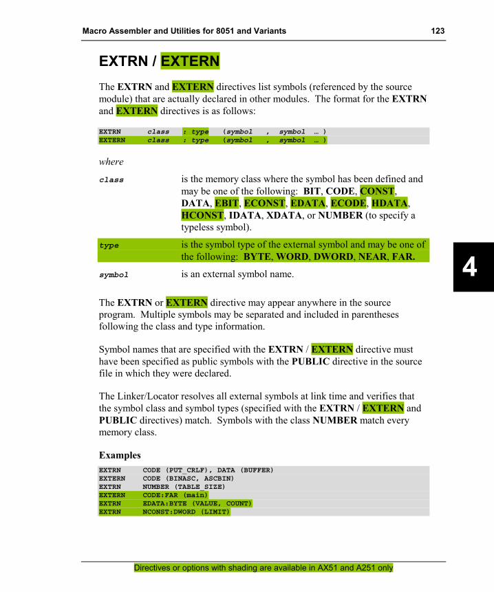
Macro Assembler and Utilities for 8051 and Variants 123
Directives or options with shading are available in AX51 and A251 only
4
EXTRN / EXTERN The EXTRN and EXTERN directives list symbols (referenced by the source module) that are actually declared in other modules. The format for the EXTRN and EXTERN directives is as follows:
EXTRN class : type (symbol , symbol … )EXTERN class : type (symbol , symbol … )
where
class is the memory class where the symbol has been defined and may be one of the following: BIT, CODE, CONST, DATA, EBIT, ECONST, EDATA, ECODE, HDATA, HCONST, IDATA, XDATA, or NUMBER (to specify a typeless symbol).
type is the symbol type of the external symbol and may be one of the following: BYTE, WORD, DWORD, NEAR, FAR.
symbol is an external symbol name.
The EXTRN or EXTERN directive may appear anywhere in the source program. Multiple symbols may be separated and included in parentheses following the class and type information.
Symbol names that are specified with the EXTRN / EXTERN directive must have been specified as public symbols with the PUBLIC directive in the source file in which they were declared.
The Linker/Locator resolves all external symbols at link time and verifies that the symbol class and symbol types (specified with the EXTRN / EXTERN and PUBLIC directives) match. Symbols with the class NUMBER match every memory class.
Examples EXTRN CODE (PUT_CRLF), DATA (BUFFER)EXTERN CODE (BINASC, ASCBIN)EXTRN NUMBER (TABLE_SIZE)EXTERN CODE:FAR (main)EXTRN EDATA:BYTE (VALUE, COUNT)EXTRN NCONST:DWORD (LIMIT)

124 Chapter 4. Assembler Directives
Directives or options with shading are available in AX51 and A251 only
4
NAME The NAME directive specifies the name to use for the object module generated for the current program. The filename for the object file is not the object module name. The object module name is embedded within the object file. The format for the NAME directive is as follows:
NAME modulename
where
modulename is the name to use for the object module and can be up to 40 characters long. The modulename must adhere to the rules for symbol names.
If a NAME directive is not present in the source program, the object module name will be the basename of the source file without the extension.
NOTE Only one NAME directive may be specified in a source file.
Example NAME PARSERMODULE

Macro Assembler and Utilities for 8051 and Variants 125
Directives or options with shading are available in AX51 and A251 only
4
Address Control The following directives allow the control of the address location counter or the control of absolute register symbols.
ORG The ORG directive is used to alter the location counter of the currently active segment and sets a new origin for subsequent statements. The format for the ORG statement is as follows:
ORG expression
where
expression must be an absolute or simple relocatable expression without any forward references. Only absolute addresses or symbol values in the current segment may be used.
When an ORG statement is encountered, the assembler calculates the value of the expression and changes the location counter for the current segment. If the ORG statement occurs in an absolute segment, the location counter is assigned the absolute address value. If the ORG statement occurs in a relocatable segment, the location counter is assigned the offset of the specified expression.
The ORG directive changes the location counter but does not produce a new segment. A possible address gap may be introduced in the segment. With absolute segments, the location counter may not reference an address prior to the base address of the segment.
NOTE The Ax51 assembler is a multi-pass assembler. Symbols are collected and the length of each instruction is determined in the first pass. In the second pass, forward references are resolved and object code is produced. For these reasons, an expression used with the ORG directive may not contain forward references.
Example ORG 100HORG RESTART
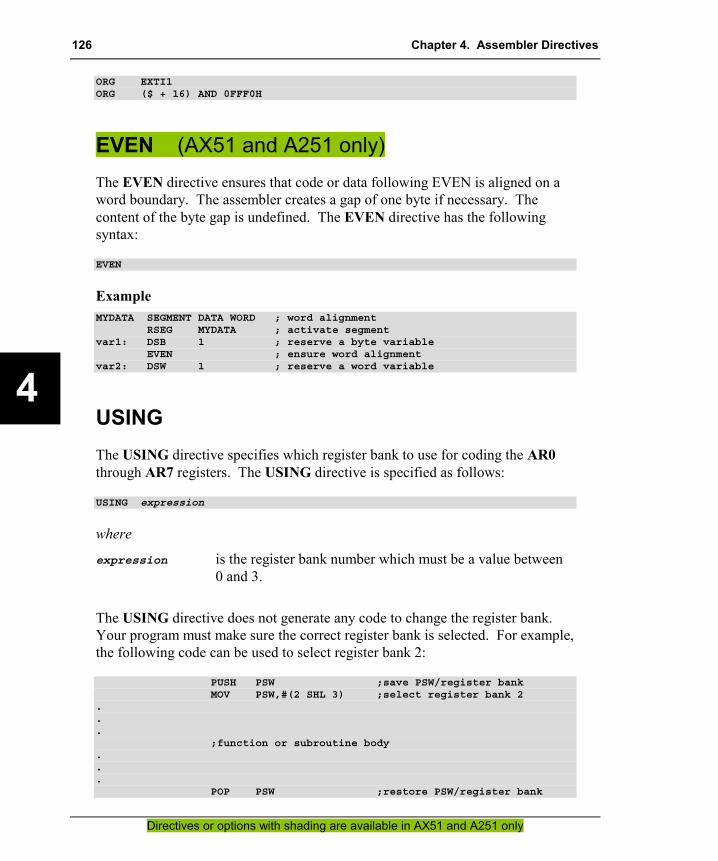
126 Chapter 4. Assembler Directives
Directives or options with shading are available in AX51 and A251 only
4
ORG EXTI1ORG ($ + 16) AND 0FFF0H
EVEN (AX51 and A251 only) The EVEN directive ensures that code or data following EVEN is aligned on a word boundary. The assembler creates a gap of one byte if necessary. The content of the byte gap is undefined. The EVEN directive has the following syntax:
EVEN
Example MYDATA SEGMENT DATA WORD ; word alignment
RSEG MYDATA ; activate segmentvar1: DSB 1 ; reserve a byte variable
EVEN ; ensure word alignmentvar2: DSW 1 ; reserve a word variable
USING The USING directive specifies which register bank to use for coding the AR0 through AR7 registers. The USING directive is specified as follows:
USING expression
where
expression is the register bank number which must be a value between 0 and 3.
The USING directive does not generate any code to change the register bank. Your program must make sure the correct register bank is selected. For example, the following code can be used to select register bank 2:
PUSH PSW ;save PSW/register bankMOV PSW,#(2 SHL 3) ;select register bank 2
.
.
.;function or subroutine body
.
.
.POP PSW ;restore PSW/register bank

Macro Assembler and Utilities for 8051 and Variants 127
Directives or options with shading are available in AX51 and A251 only
4
The register bank selected by the USING directive is marked in the object file and the memory area required by these registerbank reserved by the Linker/Locator.
The value of AR0 through AR7 is calculated as the absolute address of R0 through R7 in the register bank specified by the USING directive. Some 8051 instruction (i.e. PUSH / POP) allow you to use only absolute register addresses. By default register bank 0 is assigned to the symbols AR0 through AR7.
NOTE When the EQU directive is used to define a symbol for an ARn register, the address of the register Rn is calculated when the symbol is defined; not when it is used. If the USING directive subsequently changes the register bank, the defined symbol will not have the proper address of the ARn register and the generated code is likely to fail.
Example USING 3PUSH AR2 ; Push register 2 in bank 3
USING 1PUSH AR2 ; Push register 2 in bank 1

128 Chapter 4. Assembler Directives
Directives or options with shading are available in AX51 and A251 only
4
Other Directives
END The END directive signals the end of the assembly module. Any text in the assembly file that appears after the END directive is ignored.
The END directive is required in every assembly source file. If the END statement is excluded, Ax51 will generate a warning message.
Example END
_ _ERROR_ _ The _ _ERROR_ _ directive generates standard error messages that are report the same style as normal Ax51 assembler errors. The _ _ERROR_ _ directive is specified as follows:
__ERROR__ text
where
text is the error text that should be displayed in the listing file. The error text is also displayed on the console if the “ERRORPRINT” control described on page 189 is used.
Example IF CVAR1LEN > 10__ERROR__ "CVAR1 LEN EXCEEDS 10 BYTES"
ENDIF
$IF TESTVERS AND RELEASE__ERROR__ "TESTVERS GENERATED IN RELEASE MODE"
$ENDIF

Macro Assembler and Utilities for 8051 and Variants 129
5
Chapter 5. Assembler Macros A macro is a name that you assign to one or more assembly statements. For maximum flexibility the Ax51 macro assembler provides three different macro languages:
�� Standard Assembler Macros: are known from many other macro assemblers and allow you to define macros that look like standard assemblers instructions. Refer to “Standard Macro Directives” on page 130 for a detailed description.
�� C Macros: are known from ANSI C compilers and allow you to use common header files with constant definitions that can be used on the Ax51 macro assembler as well as on the Cx51 compiler. Refer to “C Macros” on page 145 for more information.
�� MPL Macros: are compatible with the Intel ASM-51 and allow you to retranslate existing source files that initially written for this macro assembler. The assembler control MPL enables this macro processor. If you enable MPL macros the C Macros are disabled. Refer to “Chapter 6. Macro Processing Language” on page 151 for a detailed description.
A macro processor enables you to define and to use macros in your x51 assembly programs. This section describes some of the features and advantages of using macros, lists the directives and operators that are used in macro definitions, and provides a number of example macros.
When you define a macro, you provide text (usually assembly code) that you want to associate with a macro name. Then, when you want to include the macro text in your assembly program, you provide the name of the macro. The Ax51 assembler will replace the macro name with the text specified in the macro definition.
Macros provide a number of advantages when writing assembly programs.
�� The frequent use of macros can reduce programmer induced errors. A macro allows you to define instruction sequences that are used repetitively throughout your program. Subsequent use of the macro will faithfully provide the same results each time. A macro can help reduce the likelihood of errors introduced in repetitive programming sequences. Of course, introduction of an error into a macro definition will cause that error to be duplicated where the macro is used.

130 Chapter 5. Assembler Macros
5
�� The scope of symbols used in a macro is limited to that macro. You do not need to be concerned about utilizing a previously used symbol name.
�� Macros are well suited for the creation of simple code tables. Production of these tables by hand is both tedious and error prone.
A macro can be thought of as a subroutine call with the exception that the code that would be contained in the subroutine is included in–line at the point of the macro call. However, macros should not be used to replace subroutines. Each invocation of a subroutine only adds code to call the subroutine. Each invocation of a macro causes the assembly code associated with the macro to be included in–line in the assembly program. This can cause a program to grow rapidly if a large macro is used frequently. In a static environment, a subroutine is the better choice, since program size can be considerably reduced. But in time critical, dynamic programs, macros will speed the execution of algorithms or other frequently called statements without the penalty of the procedure calling overhead.
Use the following guidelines when deciding between macros or subroutines:
�� Subroutines are best used when certain procedures are frequently executed or when memory space usage must be kept to a minimum.
�� Macros should be used when maximum processor speed is required and when memory space used is of less importance.
�� Macros can also be used to make repetitive, short assembly blocks more convenient to enter.
Standard Macro Directives Ax51 provides a number of directives that are used specifically for defining macros. These directives are listed in the following table:
Directive Description
ENDM Ends a macro definition.
EXITM Causes the macro expansion to immediately terminate.
IRP Specifies a list of arguments to be substituted, one at a time, for a specified parameter in subsequent lines.
IRPC Specifies an argument to be substituted, one character at a time, for a specified parameter in subsequent lines.

Macro Assembler and Utilities for 8051 and Variants 131
5
Directive Description
LOCAL Specifies up to 16 local symbols used within the macro.
MACRO Begins a macro definition and specifies the name of the macro and any parameters that may be passed to the macro.
REPT Specifies a repetition factor for subsequent lines in the macro.
Refer to “Assembler Controls” on page 181 as well as the following sections for more information on these and other directives.
Defining a Macro Macros must be defined in the program before they can be used. A macro definition begins with the MACRO directive which declares the name of the macro as well as the formal parameters. The macro definition must be terminated with the ENDM directive. The text between the MACRO and ENDM directives is called the macro body.
Example WAIT MACRO X ; macro definition
REPT X ; generate X NOP instructionsNOPENDM ; end REPT
ENDM ; end MACRO
In this example, WAIT is the name of the macro and X is the only formal parameter.
In addition to the ENDM directive, the EXITM directive can be used to immediately terminate a macro expansion. When an EXITM directive is detected, the macro processor stops expanding the current macro and resumes processing after the next ENDM directive. The EXITM directive is useful in conditional statements.
Example WAIT MACRO X ; macro definition
IF NUL X ; make sure X has a valueEXITM ; if not then exitENDIF
REPT X ; generate X NOP instructionsNOPENDM ; end REPT
ENDM ; end MACRO

132 Chapter 5. Assembler Macros
5
Parameters Up to 16 parameters can be passed to a macro in the invocation line. Formal parameter names must be defined using the MACRO directive.
Example MNAME MACRO P1,P2,P3,P4,P5,P6,P7,P8,P9,P10,P11,P12,P13,P14,P15,P16
defines a macro with 16 parameters. Parameters must be separated by commas in both the macro definition and invocation. The invocation line for the above macro would appear as follows:
MNAME A,B,C,D,E,F,G,H,I,J,K,L,M,N,O,P
where A, B, C, … O, P are parameters that correspond to the format parameter names P1, P2, P3, … P15, P16.
Null parameters can be passed to a macro. Null parameters have the value NULL and can be tested for using the NUL operator described later in this chapter. If a parameter is omitted from the parameter list in the macro invocation, that parameter is assigned a value of NULL.
Example MNAME A,,C,,E,,G,,I,,K,,M,,O,
P2, P4, P6, P8, P10, P12, P14, and P16 will all be assigned the value NULL when the macro is invoked. You should note that there are no spaces between the comma separators in the above invocation line. A space has an ASCII value of 20h and is not equivalent to a NULL.
Labels You can use labels within a macro definition. By default, labels used in a macro are global and if the macro is used more than once in a module, Ax51 will generate an error.
Example LOC OBJ LINE SOURCE
1 GLABEL MACRO2 LOOP: NOP3 JMP LOOP

Macro Assembler and Utilities for 8051 and Variants 133
5
4 ENDM567 GLABEL
0000 00 8+1 LOOP: NOP0001 80FD 9+1 JMP LOOP
10 GLABEL11+1 LOOP: NOP
*** _________________________^*** ERROR #9, LINE #11, ATTEMPT TO DEFINE AN ALREADY DEFINED LABEL0003 80FB 12+1 JMP LOOP
131415 END
Labels used in a macro should be local labels. Local labels are visible only within the macro and will not generate errors if the macro is used multiple times in one source file. You can define a label (or any symbol) used in a macro to be local with the LOCAL directive. Up to 16 local symbols may be defined using the LOCAL directive.
NOTE LOCAL must be in the next line after the MACRO definition.
Example CLRMEM MACRO ADDR, LEN
LOCAL LOOPMOV R7, #LENMOV R0, #ADDRMOV A, #0
LOOP: MOV @R0, AINC R0DJNZ R7, LOOPENDM
In this example, the label LOOP is local because it is defined with the LOCAL directive. Any symbol that is not defined using the LOCAL directive will be a global symbol.
Ax51 generates an internal symbol for local symbols defined in a macro. The internal symbol has the form ??0000 and is incremented each time the macro is invoked. Therefore, local labels used in a macro are unique and will not generate errors.

134 Chapter 5. Assembler Macros
5
Repeating Blocks Ax51 provides the ability to repeat a block of text within a macro. The REPT, IRP, and IRPC directives are used to specify text to repeat within a macro. Each of these directives must be terminated with an ENDM directive.
REPT The REPT directive repeats a block of text a fixed number of times. The following macro:
DELAY MACRO ;macro definitionREPT 5 ;insert 5 NOP instructionsNOPENDM ;end REPT block
ENDM ;end macro definition
inserts 5 NOP instructions when it is invoked.
Example NOPNOPNOPNOPNOP
IRP The IRP directive repeats a block once for each argument in a specified list. A specified parameter in the text block is replaced by each argument. The following macro:
CLRREGS MACRO ; macro definitionIRP RNUM, <R0,R1,R2,R3,R4,R5,R6,R7>
MOV RNUM, #0ENDM ; end IRP
ENDM ; end MACRO
replaces the argument RNUM with R0, R1, R2, … R7.

Macro Assembler and Utilities for 8051 and Variants 135
5
It generates the following code when invoked:
MOV R0, #0MOV R1, #0MOV R2, #0MOV R3, #0MOV R4, #0MOV R5, #0MOV R6, #0MOV R7, #0
IRPC The IRPC directive repeats a block once for each character in the specified argument. A specified parameter in the text block is replaced by each character. The following macro:
DEBUGOUT MACRO ; macro definitionIRPC CHR, <TEST>JNB TI, $ ; wait for xmitterCLR TIMOV A,#'CHR'MOV SBUF,A ; xmit CHRENDM ; end IRPCENDM ; end MACRO
replaces the argument CHR with the characters T, E, S, and T and generates the following code when invoked:
JNB TI, $ ; WAIT FOR XMITTERCLR TIMOV A,#'T'MOV SBUF,A ; XMIT TJNB TI, $ ; WAIT FOR XMITTERCLR TIMOV A,#'E'MOV SBUF,A ; XMIT EJNB TI, $ ; WAIT FOR XMITTERCLR TIMOV A,#'S'MOV SBUF,A ; XMIT SJNB TI, $ ; WAIT FOR XMITTERCLR TIMOV A,#'T'MOV SBUF,A ; XMIT T
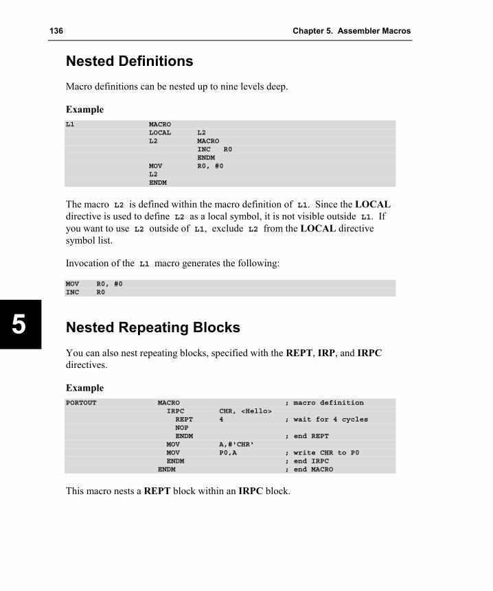
136 Chapter 5. Assembler Macros
5
Nested Definitions Macro definitions can be nested up to nine levels deep.
Example L1 MACRO
LOCAL L2L2 MACRO
INC R0ENDM
MOV R0, #0L2ENDM
The macro L2 is defined within the macro definition of L1. Since the LOCAL directive is used to define L2 as a local symbol, it is not visible outside L1. If you want to use L2 outside of L1, exclude L2 from the LOCAL directive symbol list.
Invocation of the L1 macro generates the following:
MOV R0, #0INC R0
Nested Repeating Blocks You can also nest repeating blocks, specified with the REPT, IRP, and IRPC directives.
Example PORTOUT MACRO ; macro definition
IRPC CHR, <Hello>REPT 4 ; wait for 4 cyclesNOPENDM ; end REPT
MOV A,#'CHR'MOV P0,A ; write CHR to P0ENDM ; end IRPC
ENDM ; end MACRO
This macro nests a REPT block within an IRPC block.
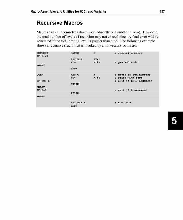
Macro Assembler and Utilities for 8051 and Variants 137
5
Recursive Macros Macros can call themselves directly or indirectly (via another macro). However, the total number of levels of recursion may not exceed nine. A fatal error will be generated if the total nesting level is greater than nine. The following example shows a recursive macro that is invoked by a non–recursive macro.
RECURSE MACRO X ; recursive macroIF X<>0
RECURSE %X–1ADD A,#X ; gen add a,#?
ENDIFENDM
SUMM MACRO X ; macro to sum numbersMOV A,#0 ; start with zero
IF NUL X ; exit if null argumentEXITM
ENDIFIF X=0 ; exit if 0 argument
EXITMENDIF
RECURSE X ; sum to 0ENDM

138 Chapter 5. Assembler Macros
5
Operators Ax51 provides a number of operators that may be used within a macro definition. The following table lists the operators and gives a description of each.
Operator Description
NUL The NUL operator can be used to determine if a macro argument is NULL. NUL generates a non–zero value if its argument is a NULL. Non–NULL arguments will generate a value of 0. The NUL operator can be used with an IF control to enable condition macro assembly.
& The ampersand character is used to concatenate text and parameters.
< > Angle brackets are used to literalize delimiters like commas and blanks. Angle brackets are required when passing these characters to a nested macro. One pair of angle brackets is required for every nesting level.
% The percent sign is used to prefix a macro argument that should be interpreted as an expression. When this operator is used, the numeric value of the following expression is calculated. That value is passed to the macro instead of the expression text.
;; A double semicolon indicates that subsequent text on the line should be ignored. The remaining text is not processed or emitted. This helps to reduce memory usage.
! If an exclamation mark is used in front of a character, that character will be literalized. This allows character operators to be passed to a macro as a parameter.

Macro Assembler and Utilities for 8051 and Variants 139
5
NUL Operator When a formal parameter in a macro call is omitted, the parameter is given a value of NULL. You can check for NULL parameters by using the NUL operator within an IF control statement in the macro. The NUL operator requires an argument. If no argument is found, NUL returns a value of 0 to the IF control.
For example, the following macro definition:
EXAMPLE MACRO XIF NUL XEXITM
ENDIFENDM
when invoked by:
EXAMPLE
will cause the IF NUL X test to pass, process the EXITM statement, and exit the macro expansion.
NOTE A blank character (‘ ’) has an ASCII value of 20h and is not equivalent to a NULL.

140 Chapter 5. Assembler Macros
5
& Operator The ampersand macro operator (&) can be used to concatenate text and macro parameters. The following macro declaration demonstrates the proper use of this operator.
MAK_NOP_LABEL MACRO XLABEL&X: NOP
ENDM
The MAK_NOP_LABEL macro will insert a new label and a NOP instruction for each invocation. The argument will be appended to the text LABEL to form the label for the line.
Example LOC OBJ LINE SOURCE
1 MAK_NOP_LABEL MACRO X2 LABEL&X: NOP3 ENDM456 MAK_NOP_LABEL 1
0000 00 7+1 LABEL1: NOP8 MAK_NOP_LABEL 2
0001 00 9+1 LABEL2: NOP10 MAK_NOP_LABEL 3
0002 00 11+1 LABEL3: NOP12 MAK_NOP_LABEL 4
0003 00 13+1 LABEL4: NOP1415 END
The MAK_NOP_LABEL macro is invoked in the above example in lines 6, 8, 10, and 12. The generated label and NOP instructions are shown in lines 7, 9, 11, and 13. Note that the labels are concatenated with the argument that is passed in the macro invocation.

Macro Assembler and Utilities for 8051 and Variants 141
5
< and > Operators The angle bracket characters ( < > ) are used to enclose text that should be passed literally to macros. Some characters; for example, the comma; cannot be passed without being enclosed within angle brackets.
The following example shows a macro declaration and invocation passing an argument list within angle brackets.
1 FLAG_CLR MACRO FLAGS2 MOV A, #03 IRP F, <FLAGS>4 MOV FLAG&F, A5 ENDM6 ENDM78 DSEG
0000 9 FLAG1: DS 10001 10 FLAG2: DS 10002 11 FLAG3: DS 10003 12 FLAG4: DS 10004 13 FLAG5: DS 10005 14 FLAG6: DS 10006 15 FLAG7: DS 10007 16 FLAG8: DS 10008 17 FLAG9: DS 1
1819 CSEG2021 FLAG_CLR <1>
0000 7400 22+1 MOV A, #023+1 IRP F, <1>24+1 MOV FLAG&F, A25+1 ENDM
0002 F500 26+2 MOV FLAG1, A27 FLAG_CLR <1,2,3>
0004 7400 28+1 MOV A, #029+1 IRP F, <1,2,3>30+1 MOV FLAG&F, A31+1 ENDM
0006 F500 32+2 MOV FLAG1, A0008 F501 33+2 MOV FLAG2, A000A F502 34+2 MOV FLAG3, A
35 FLAG_CLR <1,3,5,7>000C 7400 36+1 MOV A, #0
37+1 IRP F, <1,3,5,7>38+1 MOV FLAG&F, A39+1 ENDM
000E F500 40+2 MOV FLAG1, A0010 F502 41+2 MOV FLAG3, A0012 F504 42+2 MOV FLAG5, A0014 F506 43+2 MOV FLAG7, A..

142 Chapter 5. Assembler Macros
5
In the previous example, the FLAG_CLR macro is declared to clear any of a number of flag variables. The FLAGS argument specifies a list of arguments that are used by the IRP directive in line 3. The IRP directive repeats the instruction MOV FLAG&F, A for each parameter in the FLAGS argument.
The FLAG_CLR macro is invoked in lines 21, 27, and 35. In line 21, only one parameter is passed. In line 27, three parameters are passed, and in line 35, four parameters are passed. The parameter list is enclosed in angle brackets so that it may be referred to as a single macro parameter, FLAGS. The code generated by the macro is found in lines 26, 32–34, and 40–43.
% Operator The percent character (%) is used to pass the value of an expression to a macro rather than passing the literal expression itself. For example, the following program example shows a macro declaration that requires a numeric value along with macro invocations that use the percent operator to pass the value of an expression to the macro.
1 OUTPORT MACRO N2 MOV A, #N3 MOV P0, A4 ENDM56
00FF 7 RESET_SIG EQU 0FFh0000 8 CLEAR_SIG EQU 0
91011 OUTPORT %(RESET_SIG AND NOT 11110000b)
0000 740F 12+1 MOV A, #150002 F580 13+1 MOV P0, A
1415 OUTPORT %(CLEAR_SIG OR 11110000b)
0004 74F0 16+1 MOV A, #2400006 F580 17+1 MOV P0, A
In this example, the expressions evaluated in lines 11 and 15 could not be passed to the macro because the macro expects a numeric value. Therefore, the expressions must be evaluated before the macro. The percent sign forces Ax51 to generate a numeric value for the expressions. This value is then passed to the macro.

Macro Assembler and Utilities for 8051 and Variants 143
5
;; Operator The double semicolon operator is used to signal that the remaining text on the line should not be emitted when the macro is expanded. This operator is typically used to precede comments that do not need to be expanded when the macro is invoked.
Example REGCLR MACRO CNTREGNUM SET 0
MOV A, #0 ;; load A with 0REPT CNT ;; rpt for CNT registersMOV R®NUM, A ;; set R# to 0REGNUM SET %(REGNUM+1)ENDM
ENDM
! Operator The exclamation mark operator is used to indicate that a special character is to be passed literally to a macro. This operator enables you to pass comma and angle bracket characters, that would normally be interpreted as delimiters, to a macro.

144 Chapter 5. Assembler Macros
5
Invoking a Macro Once a macro has been defined, it can be called many times in the program. A macro call consists of the macro name plus any parameters that are to be passed to the macro.
In the invocation of a macro, the position of the actual parameters corresponds to the position of the parameter names specified in the macro definition. Ax51 performs parameter substitution in the macro starting with the first parameter. The first parameter passed in the invocation replaces each occurrence of the first formal parameter in the macro definition, the second parameter that is passed replaces the second formal parameter in the macro definition, and so on.
If more parameters are specified in the macro invocation than are actually declared in the macro definition, Ax51 ignores the additional parameters. If fewer parameters are specified than declared, Ax51 replaces the missing parameters with a NULL character.
To invoke a macro in your assembly programs, you must first define the macro. For example, the following definition:
.
.
.DELAY MACRO CNT ;macro definition
REPT CNT ;insert CNT NOP instructionsNOPENDM ;end REPT block
ENDM ;end macro definition...
defines a macro called DELAY that accepts one argument CNT. This macro will generate CNT NOP instructions. So, if CNT is equal to 3, the emitted code will be:
NOPNOPNOP

Macro Assembler and Utilities for 8051 and Variants 145
5
The following code shows how to invoke the DELAY macro from an assembly program.
.
.
.LOOP: MOV P0, #0 ;clr PORT 0
DELAY 5 ;wait 5 NOPsMOV P0, #0ffh ;set PORT 0DELAY 5 ;wait 5 NOPsJMP LOOP ;repeat
.
.
.
In this example, a value of 0 is written to port 0. The DELAY macro is then invoked with the parameter 5. This will cause 5 NOP instructions to be inserted into the program. A value of 0FFh is written to port 0 and the DELAY macro is invoked again. The program then repeats.
C Macros The Ax51 macro assembler has a standard C macro preprocessor that is almost identical with the macro preprocessors in the Cx51 compiler. This allows you to use common header files with constant definitions that can be used in assembler and C source files. The Ax51 macro assembler accepts also the special function register directives from the Cx51 compiler. Therefore you may use the same SFR register definition files for both assembler and C source files.
NOTE C Macros are not available if you have enabled the Intel ASM-51 compatible MPL macro language with the MPL assembler control.
C Macro Preprocessor Directives C macro preprocessor directives must be the first non-whitespace text specified on a line. All directives are prefixed with the pound or number-sign character (‘#’). For example:
#include <reg51f.h>#if TEST#define DEBUG 1
#endif

146 Chapter 5. Assembler Macros
5
The following table lists the preprocessor directives and gives a brief description of each.
Directive Description
define Defines a preprocessor macro or constant.
elif Initiates an alternative branch of the if condition, when the previous if, ifdef, ifndef, or elif branch was not taken.
else Initiates an alternative branch when the previous if, ifdef, or ifndef branch was not taken.
endif Ends an if, ifdef, ifndef, elif, or else block. error Outputs an error message defined by the user. This directive instructs the
compiler to emit the specified error message. ifdef Evaluates an expression for conditional compilation. The argument to be evaluated
is the name of a definition. ifndef Same as ifdef but the evaluation succeeds if the definition is not defined.
if Evaluates an expression for conditional compilation.
include Reads source text from an external file. The notation sequence determines the search sequence of the included files. Ax51 searches for include files specified with less-than/greater-than symbols (‘<’ ‘>’) in the include file folder. The include file folder is specified with the INCDIR assembler control and with the environment variable C51INC and is therefore compatible with the Cx51 compiler. Ax51 searches for include files specified with double-quotes (“ “) in the current folder, which is typically the folder of the project file.
line Specifies a line number together with an optional filename. These specifications are used in error messages to identify the error position.
pragma Allows you to specify assembler controls and are converted into Ax51 control lines. Refer to “Assembler Controls” on page 181 for more information.
undef Deletes a preprocessor macro or constant definition.
Stringize Operator The stringize or number-sign operator (‘#’), when used within a macro definition, converts a macro parameter into a string constant. This operator may be used only in a macro that has a specified argument or parameter list.
When the stringize operator immediately precedes the name of one of the macro parameters, the parameter passed to the macro is enclosed within quotation marks and is treated as a string literal. For example:
#define stringer(x) DB #x, 0x0D, 0x0A
stringer (text)

Macro Assembler and Utilities for 8051 and Variants 147
5
results in the following actual output from the preprocessor.
DB "text", 0x0D, 0x0A
NOTES The Ax51 macro assembler does not accept C escape sequences like "\n", "\r" or "\x0d". You need to replace these characters with hex values. Unlike the Cx51 compiler, multiple strings are not concatenated to a single string by the Ax51 macro assembler. Therefore you need to separate multiple items with a comma when using the Ax51 macro assembler.
Token-pasting Operator The token-pasting operator (##) within a macro definition combines two arguments. It permits two separate tokens in the macro definition to be joined into a single token.
If the name of a macro parameter used in the macro definition is immediately preceded or followed by the token-pasting operator, the macro parameter and the token-pasting operator are replaced by the value of the passed parameter. Text that is adjacent to the token-pasting operator that is not the name of a macro parameter is not affected. For example:
TEST1 EQU 0x10TEST2 EQU 0x20
#define paster(n) DB TEST##n
paster (2)
results in the following actual output from the preprocessor.
DB TEST2

148 Chapter 5. Assembler Macros
5
Predefined C Macro Constants Ax51 provides you with predefined constants to use in preprocessor directives and C code for more portable programs. The following table lists and describes each one.
Constant Description
_ _A51_ _ Allows you to identify the A51 assembler and returns the version number (for example, 600 for version 6.00). Only defined when using A51.
_ _AX51_ _ Allows you to identify the AX51 assembler and returns the version number (for example, 100 for version 1.00). Only defined when using AX51.
_ _A251_ _ Allows you to identify the A251 assembler and returns the version number (for example, 300 for version 3.00). Only defined when using A251.
_ _DATE_ _ Date when the compilation was started.
_ _FILE_ _ Name of the file being compiled.
_ _KEIL_ _ Defined to 1 to indicate that you are using a development tool from Keil Software.
_ _LINE_ _ Current line number in the file being compiled.
_ _TIME_ _ Time when the compilation was started.
_ _STDC_ _ Defined to 1 to indicate full conformance with the ANSI C Standard.
Examples with C Macros The following assembler source file shows the usage of C Macros.
#if !defined (__A51__) || __A51__ < 600#error "This source file requires A51 V6.00 or higher"
#endif
#pragma NOLIST#include <reg52.h> // register definition file for 80C52#pragma LIST
#define TEST1 10#define MYTEXT "Hello World"
#if TEST1 == 10DB MYTEXT
#endifDB "GENERATED: ", __DATE__
MOV R0,#TEST1 * 10
END
The listing file generated by A51 shows the text replacements performed by the C preprocessor:
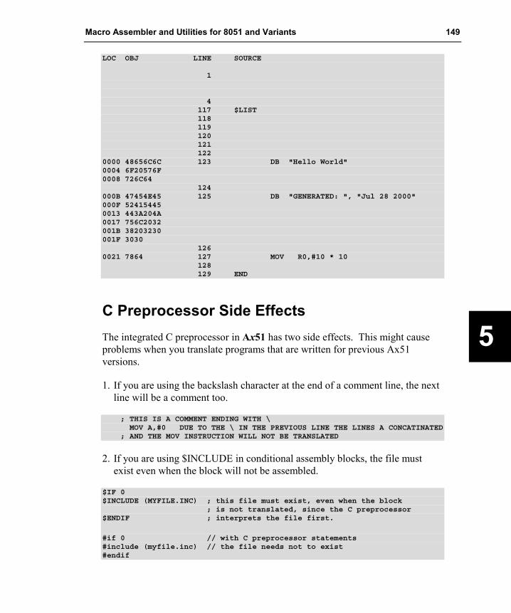
Macro Assembler and Utilities for 8051 and Variants 149
5
LOC OBJ LINE SOURCE
1
4117 $LIST118119120121122
0000 48656C6C 123 DB "Hello World"0004 6F20576F0008 726C64
124000B 47454E45 125 DB "GENERATED: ", "Jul 28 2000"000F 524154450013 443A204A0017 756C2032001B 38203230001F 3030
1260021 7864 127 MOV R0,#10 * 10
128129 END
C Preprocessor Side Effects The integrated C preprocessor in Ax51 has two side effects. This might cause problems when you translate programs that are written for previous Ax51 versions.
1. If you are using the backslash character at the end of a comment line, the next line will be a comment too.
; THIS IS A COMMENT ENDING WITH \MOV A,#0 DUE TO THE \ IN THE PREVIOUS LINE THE LINES A CONCATINATED
; AND THE MOV INSTRUCTION WILL NOT BE TRANSLATED
2. If you are using $INCLUDE in conditional assembly blocks, the file must exist even when the block will not be assembled.
$IF 0$INCLUDE (MYFILE.INC) ; this file must exist, even when the block
; is not translated, since the C preprocessor$ENDIF ; interprets the file first.
#if 0 // with C preprocessor statements#include (myfile.inc) // the file needs not to exist#endif


Macro Assembler and Utilities for 8051 and Variants 151
6
Chapter 6. Macro Processing Language The Macro Processing Language (MPL) is a string replacement facility. The macro processing language is enabled with the assembler control MPL and fully compatible to the Intel ASM-51 macro processing language. It permits you to write repeatedly used sections of code once and then insert that code at several places in your program. Perhaps MPL’s most valuable capability is conditional assembly-with all microprocessors, compact configuration dependent code is very important to good program design. Conditional assembly of sections of code can help to achieve the most compact code possible.
Overview The MPL processor views the source file in different terms than the assembler: to the assembler, the source file is a series of lines – control lines, and directive lines. To the MPL processor, the source file is a long string of characters.
All MPL processing of the source file is performed before your code is assembled. Because of this independent processing of the MPL macros and assembly of code, we must differentiate between macro-time and assembly-time. At macro-time, assembly language symbols and labels are unknown. SET and EQU symbols, and the location counter are also not known. Similarly, at assembly-time, no information about the MPL is known.
The MPL processor scans the source file looking for macro calls. A macro call is a request to the processor to replace the macro name of a built-in or user-defined macro by some replacement text.
Creating and Calling MPL Macros The MPL processor is a character string replacement facility. It searches the source file for a macro call, and then replaces the call with the macro's return value. A % character signals a macro call.

152 Chapter 6. Macro Processing Language
6
The MPL processor function DEFINE creates macros. MPL processor functions are a predefined part of the macro language, and can be called without definition. The syntax for DEFINE is:
%[*]DEFINE (macro name) [parameter-list] (macro-body)
DEFINE is the most important macro processor function. Each of the symbols in the syntax above (macro name, parameter-list, and macro-body) are described in the following.
Creating Parameterless Macros When you create a parameterless macro, there are two parts to a DEFINE call:
�� macro name The macro name defines the name used when the macro is called.
�� macro body The macro-body defines the return value of the call.
The syntax of a parameterless macro definition is shown below:
%*DEFINE (macro name) (macro-body)
The ‘ %’ is the metacharacter that signals a macro call. The ‘*’ is the literal character. The use of the literal character is described later in this part.
Macro names have the following conventions:
�� Maximum of 31 characters long
�� First character: ‘A’ - ‘Z’, ‘a’ - ‘z’, ‘_’, or ‘?’
�� Other characters: ‘A’ - ‘Z’, ‘a’ - ‘z’, ‘_’, ‘?’, ‘0’ - ‘9’
The macro-body is usually the replacement text of the macro call. However, the macro-body may contain calls to other macros. If so, the replacement text is actually the fully expanded macro-body, including the calls to other macros. When you define a macro using the syntax shown above, macro calls contained in the body of the macro are not expanded, until you call the macro.

Macro Assembler and Utilities for 8051 and Variants 153
6
The syntax of DEFINE requires that left and right parentheses surround the macro-body. For this reason, you must have balanced parentheses within the macro-body (each left parenthesis must have a succeeding right parenthesis, and each right parenthesis must have a preceding left parenthesis). We call character strings that meet these requirements balanced-text.
To call a macro, use the metacharacter followed by the macro name for the MPL macro. (The literal character is not needed when you call a user-defined macro.) The MPL processor will remove the call and insert the replacement text of the call. If the macro- body contains any call to other macros, they will be replaced with their replacement text.
Once a macro has been created, it may be redefined by a second DEFINE.
MPL Macros with Parameters Parameters in a macro body allow you to fill in values when you call the MPL macro. This permits you to design a generic macro that produces code for many operations.
The term parameter refers to both the formal parameters that are specified when the macro is defined, and the actual parameters or arguments that are replaced when the macro is called.
The syntax for defining MPL macros with parameters is:
%*DEFINE (macro-name(parameter-list)) (macro-body)
The parameter-list is a list of identifiers separated by macro delimiters. The identifier for each parameter must be unique.
Typically, the macro delimiters are parentheses and commas. When using these delimiters, you would enclose the parameter-list in parentheses and separate each formal parameter with a comma. When you define a macro using parentheses and commas as delimiters, you must use those same delimiters, when you call that macro.
The macro-body must be a balanced-text string. To indicate the locations of parameter replacement, place the parameter's name preceded by the metacharacter in the macro-body. The parameters may be used any number of times and in any order within the macro-body. If a macro has the same name as

154 Chapter 6. Macro Processing Language
6
one of the parameters, the macro cannot be called within the macro-body since this would lead to infinite recursion.
The example below shows the definition of a macro with three dummy parameters - SOURCE, DESTINATION, and COUNT. The macro will produce code to copy any number of bytes from one part of memory to another.
%*DEFINE (BMOVE (src, dst, cnt)) LOCAL lab (MOV R0,#%srcMOV R1,#%dstMOV R2,#%cnt
%lab: MOV A,@R0MOV @R1,AINC R0INC R1DJNZ R2, %lab
)
To call the above macro, you must use the metacharacter followed by the macro's name similar to simple macros without parameters. However, a list of the actual parameters must follow. The actual parameters must be surrounded in the macro definition. The actual parameters must be balanced-text and may optionally contain calls to other macros. A simple program example with the macro defined above might be:
Assembler source text %*DEFINE (BMOVE (src, dst, cnt)) LOCAL lab (
MOV R0,#%srcMOV R1,#%dstMOV R2,#%cnt
%lab: MOV A,@R0MOV @R1,AINC R0INC R1DJNZ R2, %lab
)
ALEN EQU 10 ; define the array sizeDSEC SEGMENT IDATA ; define a IDATA segmentPSEC SEGMENT CODE ; define a CODE segment
RSEG DSEC ; activate IDATA segmentarr1: DS ALEN ; define arraysarr2: DS ALEN
RSEG PSEC ; activate CODE segment; move memory block%BMOVE (arr1,arr2,ALEN)
END

Macro Assembler and Utilities for 8051 and Variants 155
6
The following listing shows the assembler listing of the above source code.
LOC OBJ LINE SOURCE
12
00000A 3 ALEN EQU 10 ; define the array size-------- 4 DSEC SEGMENT IDATA ; define a IDATA segment-------- 5 PSEC SEGMENT CODE ; define a CODE segment
6-------- 7 RSEG DSEC ; activate IDATA segment000000 8 arr1: DS ALEN ; define arrays00000A 9 arr2: DS ALEN
10-------- 11 RSEG PSEC ; activate CODE segment
12 ; move memory block13 ; %BMOVE (arr1,arr2,ALEN)14 ;15 ; MOV R0,#%src16 ; MOV R1,#%dst17 ; MOV R2,#%cnt18 ; %lab: MOV A,@R019 ; MOV @R1,A20 ; INC R021 ; INC R122 ; DJNZ R2, %lab2324 ; MOV R0,#%src25 ; arr1
000000 7E0000 F 26 MOV R0,#arr127 ; MOV R1,#%dst28 ; arr2
000003 7E1000 F 29 MOV R1,#arr230 ; MOV R2,#%cnt31 ; ALEN
000006 7E200A 32 MOV R2,#ALEN33 ; %lab: MOV A,@R034 ;LAB0
000009 A5E6 35 LAB0: MOV A,@R000000B A5F7 36 MOV @R1,A00000D A508 37 INC R000000F A509 38 INC R1
39 ; DJNZ R2, %lab40 ; LAB0
000011 A5DA00 F 41 DJNZ R2, LAB04243 END
The example lists an assembled file that contains a macro definition in lines 1 to 9. The macro definition is listed with semicolons at start of each line. These semicolons are added by the assembler to prevent assembly of the definition text which is meaningful to the MPL preprocessor, but not to the remaining assembler phases. The listing only includes macro definitions or macro calls, if the control GEN is given.

156 Chapter 6. Macro Processing Language
6
The macro BMOVE is called in line 12 with three actual parameters. Lines 14 to 20 shows the macro expansion, which is the return value of the macro call. This text will be assembled.
The example will produce assembly errors because no section directives are included in the source file. The purpose here is to show MPL processing, not the assembler semantics.
Local Symbols List The DJNZ instruction in the previous example uses a local label as the target of the branch. If you use a fixed label name (for example xlab, without a leading %), and you use the macro two or more times is the same assembly source file, errors will occur due to multiple definitions of a single name.
Local symbol definitions solve this problem. Local symbols are generated by the MPL processor as local_symbol_nnn, whereby local_symbol is the name of the local symbol and nnn is some number. Each time the macro is called, the number is automatically incremented. The resulting names are unique to each macro invocation.
The MPL processor increments a counter each time your program calls a macro that uses a LOCAL construct. The counter is incremented once for each symbol in the LOCAL list. Symbols in the LOCAL list, when used in the macro-body, receive a one to five digit suffix that is the decimal value of the counter. The first time you call a macro that uses the LOCAL construct, the suffix is 0.
The syntax for the LOCAL construct in the DEFINE functions is shown below:
%*DEFINE (macro-name (parameter-list)) [LOCAL local-list] (macro-body)
The local-list is a list of valid macro identifiers separated by spaces or commas. The LOCAL construct in a macro has no affect on the syntax of a macro call.

Macro Assembler and Utilities for 8051 and Variants 157
6
Macro Processor Language Functions The MPL processor has several predefined macro processor functions. These MPL processor functions perform many useful operations that would be difficult or impossible to produce in a user-defined macro. An important difference between a user-defined macro and a MPL processor function is that user-defined macros may be redefined, while MPL processor functions can not be redefined.
We have already seen one of these MPL processor functions, DEFINE. DEFINE creates user defined macros. MPL processor functions are already defined when the MPL processor is started.
Comment Function The MPL processing language can be very subtle, and the operation of macros written in a straightforward manner may not be immediately obvious. Therefore, it is often necessary to comment macro definitions. The comment function has the following syntax:
%'text'%'text end-of-line
The comment function always evaluates to the null string. Two terminating characters are recognized, the apostrophe and the end-of-line character. The second form allows you to spread macro definitions over several lines while avoiding unwanted end-of-lines in the return value. In either form, the text or comment is not evaluated for macro calls.
Example %'this is macro comment.' ; this is an assembler comment.
%'the complete line including end-of-line is a comment
Source text before MPL processing MOV R5, R15 %'the following line will be kept separate'MOV R1, %'this comment eats the newline characterR12
Output text from MPL processor MOV R5, R15MOV R1, R12

158 Chapter 6. Macro Processing Language
6
Escape Function Sometimes it is required to prevent the MPL processor from processing macro text. Two MPL processor functions perform this operation:
�� escape function
�� bracket function
The escape function interrupts scanning of macro text. The syntax of the escape function is:
%n text-n-characters-long
The metacharacter followed by a single decimal digit specifies the number of characters (maximum is 9) that are not evaluated. The escape function is useful for inserting a metacharacter (normally the % character), a comma, or a parenthesis.
Example 10%1% OF 10 = 1; expands to: 10% OF 10 = 1;ASM%0251 expands to: ASM251
Bracket Function The other MPL processor function that inhibits the processing of macro text is the bracket function. The syntax of the bracket function is:
%(balanced-text)
The bracket function disables all MPL processing of the text contained within the parentheses. However, the escape function, the comment function, and parameter substitution are still recognized.
Since there is no restriction for the length of the text within the bracket function, it is usually easier to use than the escape function.
Example ASM%(251) evaluates to: ASM251%(1,2,3,4,5) evaluates to: 1,2,3,4,5

Macro Assembler and Utilities for 8051 and Variants 159
6
Macro definition of ‘DW’ %*DEFINE (DW (LIST, LABEL)) (%LABEL: DW %LIST)
Macro call to ‘DW’ %DW (%(120, 121, 122, 123, -1), TABLE)
Return value of the macro call to ‘DW’ TABLE: DW 120, 121, 122, 123, -1
The macro above will add word definitions to the source file. It uses two parameters: one for the word expression list and one for the label name. Without the bracket function it would not be possible to pass more than one expression in the list, since the first comma would be interpreted as the delimiter separating the actual parameters to the macro. The bracket function used in the macro call prevents the expression list (120, 121, 122, 123, -1) from being evaluated as separate parameters.
METACHAR Function The MPL processor function METACHAR allows the programmer to change the character that will be recognized by the MPL processor as the metacharacter. The use of this function requires extreme care.
The syntax of the METACHAR function is:
%METACHAR (balanced_text)
The first character of the balanced text is taken to be the new value of the metacharacter. The characters @, (, ), *, blank, tab, and identifier-characters are not allowed to be the metacharacter.
Example %METACHAR (!) ; change metacharacter to '!'!(1,2,3,4) ; bracket function invoked with !
160 Chapter 6. Macro Processing Language
6
Numbers and Expressions Balanced text strings appearing in certain places in built-in MPL processor functions are interpreted as numeric expressions:
�� The argument to evaluate function 'EVAL'
�� The argument to the flow of control functions 'IF', 'WHILE', 'REPEAT' and 'SUBSTR'.
Expressions are processed as follows:
�� The text of the numeric expression will be expanded in the ordinary manner of evaluating an argument to a macro function.
�� The resulting string is evaluated to both a numeric and character representation of the expressions result. The return value is the character representation.
The following operators are allowed (shown in order of precedence).
1. Parenthesized Expressions
2. HIGH, LOW
3. *, /, MOD, SHL, SHR
4. EQ, LT, LE, GT, GE, NE
5. NOT
6. AND, OR, XOR
The arithmetic is done using signed 16-bit integers. The result of the relational operators is either 0 (FALSE) or 1 (TRUE).

Macro Assembler and Utilities for 8051 and Variants 161
6
Numbers Numbers can be specified in hexadecimal (base 16), decimal (base 10), octal (base 8) and binary (base 2). A number without an explicit base is interpreted as decimal, this being the default representation. The first character of a number must always be a digit between 0 and 9. Hexadecimal numbers which do not have a digit as the first character must have a 0 placed in front of them.
Base Suffix Valid Characters Examples
hexadecimal H,h 0 - 9, A-F (a - f) 1234H 99H 123H 0A0F0H 0FFH Hexadecimal numbers must be preceded with a 0, if the first
digit is in range A to F decimal D,d 0 - 9 1234 65590D 20d 123 octal O,o,Q,q 0 - 7 177O 7777o 25O 123o 177777O binary B,b 0 - 1 1111B 10011111B 101010101B
Dollar ($) signs can be placed within the numbers to make them more readable. However a $ sign is not allowed to be the first or last character of a number and will not be interpreted.
1111$0000$1010$0011B is equivalent to 1111000010100011B
1$2$3$4 is equivalent to 1234
Hexadecimal numbers may be also entered using the convention from the C language:
0xFE02 0x12340X5566 0x0A

162 Chapter 6. Macro Processing Language
6
Character Strings The MPL processor allows ASCII characters strings in expressions. An expression is permitted to have a string consisting of one or two characters enclosed in single quote characters (').
'A' evaluates to 0041H
'AB' evaluates to 4142H
'a' evaluates to 0061H
'ab' evaluates to 6162H
'' the null string is not valid!
'abc' ERROR due to more than two characters
The MPL processor cannot access the assembler's symbol table. The values of labels, SET and EQU symbols are not known during MPL processing. But, the programmer can define macro-time symbols with the MPL processor function 'SET'.

Macro Assembler and Utilities for 8051 and Variants 163
6
SET Function The MPL processor function SET permits you to define macro-time symbols. SET takes two arguments: a valid identifier, and a numeric expression.
The syntax of the SET function is:
%SET (identifier,expression)
SET assigns the value of the numeric expression to the identifier.
The SET function affects the MPL processor symbol table only. Symbols defined by SET can be redefined with a second SET function call, or defined as a macro with DEFINE.
Source text %SET (CNT, 3)%SET (OFS, 16)MOV R1,#%CNT+%OFS%SET (OFS, %OFS + 10)OFS = %OFS
Output text MOV R1,#3+16OFS = 26
The SET symbol may be used in the expression that defines its own value:
Source text %SET (CNT, 10) %' define variable CNT'%SET (OFS, 20) %' define variable OFS'
% 'change values for CNT and OFS' %SET (CNT, %CNT+%OFS) %' CNT = 30'%SET (OFS, %OFS * 2) %' OFS = 40'MOV R2,#%CNT + %OFS %' 70'MOV R5,#%CNT %' 30'
Output text MOV R2,#30 + 40MOV R5,#30
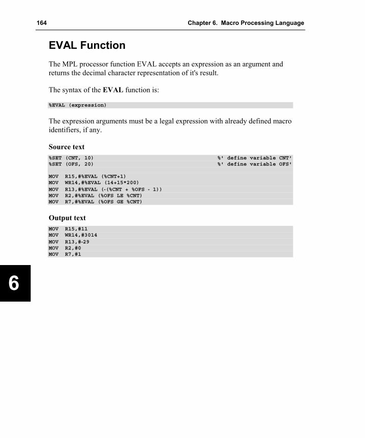
164 Chapter 6. Macro Processing Language
6
EVAL Function The MPL processor function EVAL accepts an expression as an argument and returns the decimal character representation of it's result.
The syntax of the EVAL function is:
%EVAL (expression)
The expression arguments must be a legal expression with already defined macro identifiers, if any.
Source text %SET (CNT, 10) %' define variable CNT'%SET (OFS, 20) %' define variable OFS'
MOV R15,#%EVAL (%CNT+1)MOV WR14,#%EVAL (14+15*200)MOV R13,#%EVAL (-(%CNT + %OFS - 1))MOV R2,#%EVAL (%OFS LE %CNT)MOV R7,#%EVAL (%OFS GE %CNT)
Output text MOV R15,#11MOV WR14,#3014MOV R13,#-29MOV R2,#0MOV R7,#1

Macro Assembler and Utilities for 8051 and Variants 165
6
Logical Expressions and String Comparison The following MPL processor functions compare two balanced-text string arguments and return a logical value based on that comparison. If the function evaluates to TRUE, then it returns a value of 1. If the function evaluates to FALSE, then it returns a value of 0. The list of string comparison functions below shows the syntax and describes the type of comparison made for each. Both arguments to these function may contain macro calls. (These MPL calls are expanded before the comparison is made).
%EQS (arg1,arg2) True if both arguments are identical
%NES (arg1,arg2) True if arguments are different in any way
%LTS (arg1,arg2) True if first argument has a lower value than second argument
%LES (arg1,arg2) True if first argument has a lower value then second argument or if both arguments are identical
%GTS (arg1,arg2) True if first argument has a higher value than second argument
%GES (arg1,arg2) True if first argument has a higher value than second argument or if both arguments are identical
Example %EQS (A251, A251) 0 (FALSE), the space after the comma is part of the
second argument LT%S (A251,a251) 1 (TRUE), the lower case characters have a higher ASCII
value than upper case %GTS (10,16) 0 (FALSE), these macros compare strings not numerical
values. ASCII '6' is greater than ASCII '1' %GES (a251,a251 ) 0 (FALSE), the space at the end of the second argument
makes the second argument greater than the first %*DEFINE (VAR1) (A251)%*DEFINE (VAR2) (%VAR1)%EQS (%VAR1,%VAR2)%EQS(A251,A251)
1 (TRUE) expands to:

166 Chapter 6. Macro Processing Language
6
Conditional MPL Processing Some MPL functions accept logical expressions as arguments. The MPL uses the value 1 and 0 to determine TRUE or FALSE. If the value is one, then the expression is TRUE. If the value is zero, then the expression is FALSE.
Typically, you will use either the relational operators (EQ, NE, LE, LT, GT, or GE) or the string comparison functions (EQS, NES, LES, LTS, GTS, or GES) to specify a logical value.
IF Function The IF MPL function evaluates a logical expression, and based on that expression, expands or skips its text arguments. The syntax of the MPL processor function IF is:
%IF (expression) THEN (balanced-text1) [ ELSE (balanced-text2) ] FI
IF first evaluates the expression, if it is TRUE, then balanced-text1 is expanded; if it is FALSE and the optional ELSE clause is included, then balanced-text2 is expanded. If it is FALSE and the ELSE clause is not included, the IF call returns a null string. FI must be included to terminate the call.
IF calls can be nested; when they are, the ELSE clause refers to the most recent IF call that is still open (not terminated by FI). FI terminates the most recent IF call that is still open.
Source text %*DEFINE (ADDSUB (op,p1,p2)) (%IF (%EQS (%op,ADD)) THEN (ADD %p1,%p2)ELSE (%IF (%EQS (%op,SUB)) THEN (SUB %p1,%p2) FI
) FI)
%ADDSUB (ADD,R15,R3) %' generate ADD R15,R3'%ADDSUB (SUB,R15,R9) %' generate SUB R15,R9'%ADDSUB (MUL,R15,R4) %' generates nothing !'
Output text ADD R15,R3SUB R15,R9

Macro Assembler and Utilities for 8051 and Variants 167
6
WHILE Function Often you may wish to perform macro operations until a certain condition is met. The MPL processor function WHILE provides this facility.
The syntax for the MPL processor function WHILE is:
%WHILE (expression) (balanced-text)
WHILE first evaluates the expression. If it is TRUE, then the balanced-text is expanded; otherwise, it is not. Once the balanced-text has been expanded, the logical argument is retested and if it is still TRUE, then the balanced-text is again expanded. This loop continues until the logical argument proves FALSE.
Since the MPL continues processing until expression evaluates to FALSE, the balanced-text should modify the expression, or the WHILE may never terminate.
A call to the MPL processor function EXIT will always terminate a WHILE function. EXIT is described later.
Source text %SET (count, 5) %' initialize count to 5'%WHILE (%count GT 0)( ADD R15,R15 %SET (count, %count - 1))
Output text ADD R15,R15ADD R15,R15ADD R15,R15ADD R15,R15ADD R15,R15
REPEAT Function The MPL processor function REPEAT expands its balanced-text a specified number of times. The syntax for the MPL processor function REPEAT is:
%REPEAT (expression) (balanced-test)
REPEAT uses the expression for a numerical value that specifies the number of times the balanced-text will be expanded. The expression is evaluated once

168 Chapter 6. Macro Processing Language
6
when the macro is first called, then the specified number of iterations is performed.
Source text %REPEAT (5)( -enter any key to shut down-)
%REPEAT (5) (+%REPEAT (9) (-))+
Output text -enter any key to shut down--enter any key to shut down--enter any key to shut down--enter any key to shut down--enter any key to shut down-
EXIT Function The EXIT MPL processor function terminates expansion of the most recently called REPEAT, WHILE or user-defined macro function. It is most commonly used to avoid infinite loops (example: a WHILE that never becomes FALSE, or a recursive user-defined macro that never terminates). It allows several exit points in the same macro.
The syntax for the MPL processor function EXIT is:
%EXIT
Source text %SET (count, 0)
%WHILE (1)(%IF (%count GT 5) THEN (%EXIT)FI DW %count, -%count%SET (count, %count + 1))
Output text DW 0, -0DW 1, -1DW 2, -2DW 3, -3DW 4, -4DW 5, -5

Macro Assembler and Utilities for 8051 and Variants 169
6
String Manipulation Functions The purpose of the MPL is to manipulate character strings. Therefore, there are several MPL functions that perform common character string manipulations.
LEN Function The MPL processor function LEN returns the length of the character string argument in hexadecimal: The character string is limited to 256 characters.
The syntax for the MPL processor function LEN is:
%LEN (balanced-text)
Source text %LEN (A251) %' len = 4'%LEN (A251,A251) %' comma counts also'%LEN ()%LEN (ABCDEFGHIJKLMNOPQRSTUVWXYZ)%DEFINE (TEXT) (QUEEN)%DEFINE (LENGTH) (%LEN (%TEXT))LENGTH OF '%TEXT' = %LENGTH.
Output text 49026LENGTH OF 'QUEEN' = 5.

170 Chapter 6. Macro Processing Language
6
SUBSTR Function The MPL processor function SUBSTR returns a substring of the given text argument. The function takes three arguments: a character string to be divided and two numeric arguments.
The syntax for the MPL processor function SUBSTR is:
%SUBSTR (balanced-text,expression1,expression2)
Where balanced-text is any text argument, possibly containing macro calls. Expression1 specifies the starting character of the substring. Expression2 specifies the number of characters to be included in the substring.
If expression1 is zero or greater than the length of the argument string, then SUBSTR returns the null string. The index of the first character of the balanced text is one.
If expression2 is zero, then SUBSTR returns the null string. If expression2 is greater than the remaining length or the string, then all characters from the start character to the end of the string are included.
Source text %DEFINE (STRING) (abcdefgh)%SUBSTR (%string, 1, 2)%SUBSTR (%(1,2,3,4,5), 3, 20)
Output text ab2,3,4,5

Macro Assembler and Utilities for 8051 and Variants 171
6
MATCH Function The MPL processor function MATCH searches a character string for a delimiter character, and assigns the substrings on either side of the delimiter to the identifiers.
The syntax for the MPL processor function MATCH is:
%MATCH (identifier1 delimiter identifier2) (balanced-text)
Identifier1 and identifier2 must be valid macro identifiers. Delimiter is the first character to follow identifier1. Typically, a space or comma is used, but any character that is not a macro identifier character may be used. Balanced-text is the text searched by the MATCH function. It may contain macro calls.
MATCH searches the balanced-text string for the specified delimiter. When the delimiter is found, then all characters to the left are assigned to identifier1 and all characters to the right are assigned to identifier2. If the delimiter is not found, the entire balanced-text string is assigned to identifier1 and the null string is assigned to identifier2.
Source text %DEFINE (text) (-1,-2,-3,-4,-5)%MATCH (next,list) (%text)%WHILE (%LEN (%next) NE 0)( MOV R8,#%next
MOV @WR2,R8 %MATCH (next,list)(%list)INC WR2,#1
)
Output text MOV R8,#-1MOV @WR2,R8INC WR2,#1MOV R8,#-2MOV @WR2,R8INC WR2,#1MOV R8,#-3MOV @WR2,R8INC WR2,#1MOV R8,#-4MOV @WR2,R8INC WR2,#1MOV R8,#-5MOV @WR2,R8INC WR2,#1

172 Chapter 6. Macro Processing Language
6
Console I/O Functions There are two MPL processor functions that perform console I/O: IN and OUT. Their names describe the function each performs. IN outputs a character '>' as a prompt, and returns the line typed at the console. OUT outputs a string to the console; a call to OUT is replaced by the null string.
The syntax for the MPL processor functions IN and OUT is:
%IN%OUT (balanced-text)
Source text %OUT (enter baud rate)%set (BAUD_RATE,%in)BAUD_RATE = %BAUD_RATE
Output text <19200 was entered at the console>BAUD_RATE = 19200

Macro Assembler and Utilities for 8051 and Variants 173
6
Advanced Macro Processing The MPL definition function associates an identifier with a functional string. The macro may or may not have an associated pattern consisting of parameters and/or delimiters. Optionally present are local symbols.
The syntax for a macro definition is:
%DEFINE (macro_id define_pattern) [LOCAL id_list] (balanced_text)
The define_pattern is a balanced string which is further analyzed by the MPL processor as follows:
define_pattern = { [parm_id] [delimiter_specifier] }
Delimiter_specifier is one of the following:
�� A string that contains no non-literal id-continuation, logical blank, or at character (‘@’).
�� @delimiter_id
The macro call must have a call pattern which corresponds to the macro define pattern. Regardless of the type of delimiter used to define a macro, once it has been defined, only delimiters used in the definition can be used in the macro call. Macros defined with parentheses and commas require parentheses and commas in the macro call. Macros defined with spaces or any other delimiter require that delimiter when called.
The define pattern may have three kinds of delimiters: implied blank delimiters, identifier delimiters and literal delimiters.
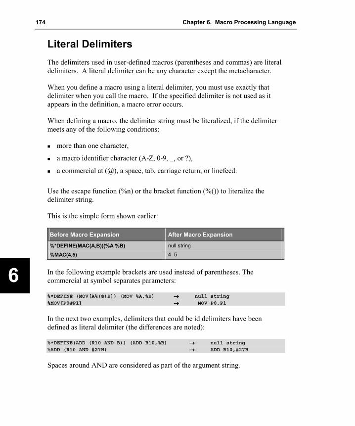
174 Chapter 6. Macro Processing Language
6
Literal Delimiters The delimiters used in user-defined macros (parentheses and commas) are literal delimiters. A literal delimiter can be any character except the metacharacter.
When you define a macro using a literal delimiter, you must use exactly that delimiter when you call the macro. If the specified delimiter is not used as it appears in the definition, a macro error occurs.
When defining a macro, the delimiter string must be literalized, if the delimiter meets any of the following conditions:
�� more than one character,
�� a macro identifier character (A-Z, 0-9, _, or ?),
�� a commercial at (@), a space, tab, carriage return, or linefeed.
Use the escape function (%n) or the bracket function (%()) to literalize the delimiter string.
This is the simple form shown earlier:
Before Macro Expansion After Macro Expansion
%*DEFINE(MAC(A,B))(%A %B) null string
%MAC(4,5) 4 5
In the following example brackets are used instead of parentheses. The commercial at symbol separates parameters:
%*DEFINE (MOV[A%(@)B]) (MOV %A,%B) →→→→ null string%MOV[P0@P1] →→→→ MOV P0,P1
In the next two examples, delimiters that could be id delimiters have been defined as literal delimiter (the differences are noted):
%*DEFINE(ADD (R10 AND B)) (ADD R10,%B) →→→→ null string%ADD (R10 AND #27H) →→→→ ADD R10,#27H
Spaces around AND are considered as part of the argument string.

Macro Assembler and Utilities for 8051 and Variants 175
6
Blank Delimiters Blank delimiters are the easiest to use. Blank delimiter is one or more spaces, tabs or new lines (a carriage-return/linefeed pair) in any order. To define a macro that uses the blank delimiter, simply place one or more spaces, tabs, or new lines surrounding the parameter list.
When the macro defined with the blank delimiter is called, each delimiter will match a series of spaces, tabs, or new lines. Each parameter in the call begins with the first non-blank character, and ends when a blank character is found.
Source text %*DEFINE (X1 X2 X3) (P2=%X2, P3=%X3)%X1 assembler A251
Output text P2=assembler, P3=A251
Identifier Delimiters Identifier delimiters are legal macro identifiers designated as delimiters. To define a macro that uses an identifier delimiter, you must prefix the delimiter with the @ symbol. You must separate the identifier delimiter from the macro identifiers (formal parameters or macro name) by a blank character.
When calling a macro defined with identifier delimiters, a blank delimiter is required to precede the identifier delimiter, but none is required to follow the identifier delimiter.
Source text %*DEFINE (ADD X1 @TO X2 @STORE X3)(MOV R1,%X1MOV R2,%X2ADD R1,R2MOV %X3,R1
)
%ADD VAR1 TO VAR2 STORE VAR3
Output text MOV R1,VAR1MOV R2,VAR2

176 Chapter 6. Macro Processing Language
6
ADD R1,R2MOV VAR3,R1
Literal and Normal Mode In normal mode, the MPL processor scans for the metacharacter. If it is found, parameters are substituted and macros are expanded. This is the usual operation of the MPL processor.
When the literal character (*) is placed in a DEFINE function, the MPL processor shifts to literal mode while expanding the macro. The effect is similar to surrounding the entire call with the bracket function. Parameters to the literalized call are expanded, the escape, comment, and bracket functions are also expanded, but no further processing is performed. If there are any calls to other macros, they are not expanded.
If there are no parameters in the macro being defined, the DEFINE function can be called without literal character. If the macro uses parameters, the MPL processor will attempt to evaluate the formal parameters in the macro-body as parameterless macro calls.
The following example illustrates the difference between defining a macro in literal mode and normal mode:
%SET (TOM, 1)%*DEFINE (AB) (%EVAL (%TOM))%DEFINE (CD) (%EVAL (%TOM))
When AB and CD are defined, TOM is equal to 1. The macro body of AB has not been evaluated due to the literal character, but the macro body of CD has been completely evaluated, since the literal character is not used in the definition. Changing the value of TOM has no effect on CD, but it changes the value of AB:
%SET (TOM,2) →→→→ null string%AB →→→→ 2%CD →→→→ 1%*CD →→→→ 1%*AB →→→→ %EVAL (%TOM)

Macro Assembler and Utilities for 8051 and Variants 177
6
MACRO Errors The MPL processor emits error messages if errors occur in the MPL processing phase. Macro errors are displayed like other assembly errors in the listing file. The following table lists the error messages generated by the MPL processor.
Number Error Message and Description
200 PREMATURE END OF FILE
The end of the source module was reached while processing some macro call, which requires more input from the source file.
201 '<token>' IDENTIFIER EXPECTED
The MPL processor expected an identifier while processing some macro. None was found. The unexpected token is displayed with this error message.
202 MPL FUNCTION '<name>': '<character>' EXPECTED
The context of the MPL processor language requires a specific character from the input given by <character> while processing the built-in function given by <name>.
203 <string>: UNBALANCED PARENTHESES
A balanced string requires the same number of right parentheses and left parentheses. 204 EXPECTED '<token>'
The syntax requires a specific token to follow, for example THEN after the balanced text argument to IF.
205 INCOMPLETE MACRO DEFINITION
The macro definition has not been completely processed due to premature end of input file.
206 FUNCTION 'MATCH': ILLEGAL CALL PATTERN
The built-in function MATCH was called with an illegal call pattern. The call pattern must consist of some formal name followed by a delimiter specification and another formal name.
207 FUNCTION 'EXIT' IN BAD CONTEXT
The built-in function EXIT is allowed only in the loop control constructs WHILE and REPEAT.
208 ILLEGAL METACHARACTER '<character>'
The first character of the balanced text argument to METACHAR is taken to be the new value of the metacharacter. The characters @, (, ), *, blank, tab, and identifier-characters are not allowed to be the metacharacter.
209 CALL PATTERN - DELIMITER '<delimiter>' NOT FOUND
The call pattern of some macro does not conform to the define pattern of that macro. The delimiters of the macro call should be checked for conformance.
210 CALL TO UNDEFINED MACRO '<name>'
The macro call specifies the name of an undefined macro. 211 INVALID MPL COMMAND '%<character>'
The character following the metacharacter does not form a valid MPL command.

178 Chapter 6. Macro Processing Language
6
Number Error Message and Description
212 INVALID DIGIT '<character>' IN NUMBER
A number of an expression contains an invalid digit. 213 UNCLOSED STRING OR CHARACTER CONSTANT
214 INVALID STRING OR CHARACTER CONSTANT
The string representing a number in an expression is invalid. The string must be either one or two characters long. A character constant must not be longer than one character. Strings or character constants must be enclosed by single or double quotes.
215 UNKNOWN EXPRESSION IDENTIFIER
The identifier within some expression is not an operator or a number. 216 <character>: INVALID EXPRESSION TOKEN
The given character does not form a valid operator or an identifier operator. 217 DIV/MOD BY ZERO
A division or modulo by zero error occurred while evaluating an expression. 218 EVAL: SYNTAX ERROR IN EXPRESSION
The expression to be evaluated contains a syntax error, for example two consecutive number, not separated by an operator.
219 CAN'T OPEN FILE '<file>'
The file specified in the INCLUDE directive could not be opened. 220 '<file>' IS NOT A DISK FILE
The file name given in the INCLUDE directive does not specify a disk file. Files other than disk files are not allowed (example: CON).
221 ERROR IN INCLUDE DIRECTIVE
The INCLUDE directive is ill-formed. The argument to INCLUDE must be the name of some file, enclosed in parentheses.

Macro Assembler and Utilities for 8051 and Variants 179
7
Chapter 7. Invocation and Controls This chapter explains how to use Ax51 to assemble x51 assembly source files and discusses the assembler controls that may be specified on the command line and within the source file.
Using the controls described in this chapter, you can specify which operations are performed by Ax51. For example, you can direct Ax51 to generate a listing file, produce cross reference information, and control the amount of information included in the object file. You can also conditionally assemble sections of code using the conditional assembly controls.
Environment Settings To run the Ax51 macro assembler and the utilities from a Windows command prompt, you must create new entries in the environment table. In addition, you must specify a PATH for the compiler folder. The following table lists the environment variables, their default paths, and a brief description.
Variable Path Description
PATH KEIL\C51\BIN or KEIL\C251\BIN
This environment variable specifies the path of the Ax51 executable programs.
TMP This environment variable specifies which path to use for temporary files generated by the assembler. If the specified path does not exist, the assembler generates an error and aborts compilation.
C51INC KEIL\C51\INC
This environment variable specifies the location of the standard C51 or CX51 include files.
C251INC KEIL\C251\INC
This environment variable specifies the location of the standard C251 include files.
Typically, these environment settings are automatically placed in your AUTOEXEC.BAT file. However, to put these settings in a separate batch file, use the following example as guideline:
PATH = C:\KEIL\C51\BINSET TMP = D:\SET C51INC = C:\KEIL\C51\INC

180 Chapter 7. Invocation and Controls
8
Running Ax51 The Ax51 assembler is invoked by typing the program name at the Windows command prompt. On this command line, you must include the name of the assembler source file to be translated, as well as any other necessary assembler controls required to translate your source file. The format for the Ax51 command line is:
A51 sourcefile ����directives…����
AX51 sourcefile ����directives…����
A251 sourcefile ����directives…����
or: A51 @commandfileAX51 @commandfileA251 @commandfile
where
sourcefile is the name of the source program you want to assemble.
controls are used to direct the operation of the assembler. Refer to “Assembler Controls” on page 181 for more information.
commandfile is the name of a command input file that may contain sourcefile and directives. A commandfile is used, when the Ax51 invocation line gets complex and exceeds the limits of the Windows command prompt.
The following command line example invokes A251 macro assembler and specifies the source file SAMPLE.A51 and uses the controls DEBUG, XREF, and PAGEWIDTH.
A251 SAMPLE.A51 DEBUG XREF PAGEWIDTH(132)
A251 displays the following information upon successful invocation and assembly.
A251 MACRO ASSEMBLER V3.00
ASSEMBLY COMPLETE. 0 ERROR(S) 0 WARNING(S)

Macro Assembler and Utilities for 8051 and Variants 181
7
ERRORLEVEL After assembly, the number of errors and warnings detected is output to the screen. Ax51 then sets the ERRORLEVEL to indicate the status of the assembly. The ERRORLEVEL values are identical for all the Ax51 assembler, Lx51 linker/locater and other x51 utilities. The values are listed in the following table:
ERROR LEVEL Meaning
0 No ERRORS or WARNINGS
1 WARNINGS only
2 ERRORS and possibly also WARNINGS
3 FATAL ERRORS
You can access the ERRORLEVEL variable in batch files for conditional tests to terminate the batch processing when an error occurs. Refer to the Windows on-line help for more information about ERRORLEVEL or batch files.
Output Files Ax51 generates a number of output files during assembly. By default, these files use the same basename as the source file, but with a different file extension. The following table lists the files and gives a brief description of each.
File Extension Description basename.LST Files with this extension are listing files that contain the formatted source
text along with any errors detected by the assembler. Listing files may optionally contain symbols used and the generated assembly code. Refer to “PRINT / NOPRINT” on page 205 for more information.
basename.OBJ Files with this extension are object modules that contain relocatable object code. Object modules can be linked into an absolute object module by the Lx51 Linker/Locator. Refer to “OBJECT / NOOBJECT” on page 203 for more information.
Assembler Controls Ax51 provides a number of controls that you can use to direct the operation of the assembler. Controls can be specified after the filename on the invocation line or in a control line within the source file. Control lines are prefixed by the dollar sign character (‘$’).

182 Chapter 7. Invocation and Controls
8
Example A51 TESTFILE.A51 MPL DEBUG XREF
or
$MPL$DEBUG$XREF
or
$MPL DEBUG XREF
In the above example, MPL, DEBUG, and XREF are all control commands and TESTFILE.A51 is the source file to assemble.
Ax51 has two classes of controls: primary and general. Primary controls are specified in the invocation line on the first few lines of the assembly source file. Primary controls remain in effect throughout the assembly. For this reason, primary controls may be used only in the invocation line or in control lines at the beginning of the program. Only other control lines that do not contain the INCLUDE control may precede a line containing a primary control. The INCLUDE control marks the end of any primary control specifications.
If a primary control is specified in the invocation line and on the first few lines of the assembly source file, the specification on the invocation line is used. This enables you override primary controls via the invocation line.
The general controls are used to control the immediate action of the assembler. Typically their status is set and modified during the assembly. Control lines containing only general controls may be placed anywhere in your source code.
The table on the next page lists all of the controls, their abbreviations, their default values, and a brief description of each.
NOTE Some controls like EJECT and SAVE cannot be specified on the command line. The syntax for each control is the same when specified on the command line or when specified within the source file. Ax51 will generate a fatal error for controls that are improperly specified.
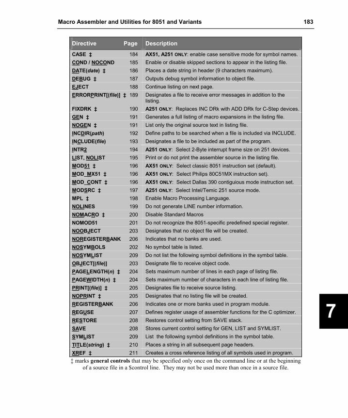
Macro Assembler and Utilities for 8051 and Variants 183
7
Directive Page Description
CASE ‡ 184 AX51, A251 ONLY: enable case sensitive mode for symbol names. COND / NOCOND 185 Enable or disable skipped sections to appear in the listing file. DATE(date) ‡ 186 Places a date string in header (9 characters maximum). DEBUG ‡ 187 Outputs debug symbol information to object file. EJECT 188 Continue listing on next page. ERRORPRINT[(file)] ‡ 189 Designates a file to receive error messages in addition to the
listing. FIXDRK ‡ 190 A251 ONLY: Replaces INC DRk with ADD DRk for C-Step devices.GEN ‡ 191 Generates a full listing of macro expansions in the listing file. NOGEN ‡ 191 List only the original source text in listing file. INCDIR(path) 192 Define paths to be searched when a file is included via INCLUDE. INCLUDE(file) 193 Designates a file to be included as part of the program. INTR2 194 A251 ONLY: Select 2-Byte interrupt frame size on 251 devices. LIST, NOLIST 195 Print or do not print the assembler source in the listing file. MOD51 ‡ 196 AX51 ONLY: Select classic 8051 instruction set (default). MOD_MX51 ‡ 196 AX51 ONLY: Select Philips 80C51MX instruction set). MOD_CONT ‡ 196 AX51 ONLY: Select Dallas 390 contiguious mode instruction set. MODSRC ‡ 197 A251 ONLY: Select Intel/Temic 251 source mode. MPL ‡ 198 Enable Macro Processing Language. NOLINES 199 Do not generate LINE number information. NOMACRO ‡ 200 Disable Standard Macros NOMOD51 201 Do not recognize the 8051-specific predefined special register. NOOBJECT 203 Designates that no object file will be created. NOREGISTERBANK 206 Indicates that no banks are used. NOSYMBOLS 202 No symbol table is listed. NOSYMLIST 209 Do not list the following symbol definitions in the symbol table. OBJECT[(file)] 203 Designate file to receive object code. PAGELENGTH(n) ‡ 204 Sets maximum number of lines in each page of listing file. PAGEWIDTH(n) ‡ 204 Sets maximum number of characters in each line of listing file. PRINT[(file)] ‡ 205 Designates file to receive source listing. NOPRINT ‡ 205 Designates that no listing file will be created. REGISTERBANK 206 Indicates one or more banks used in program module. REGUSE 207 Defines register usage of assembler functions for the C optimizer. RESTORE 208 Restores control setting from SAVE stack. SAVE 208 Stores current control setting for GEN, LIST and SYMLIST. SYMLIST 209 List the following symbol definitions in the symbol table. TITLE(string) ‡ 210 Places a string in all subsequent page headers. XREF ‡ 211 Creates a cross reference listing of all symbols used in program. ‡ marks general controls that may be specified only once on the command line or at the beginning
of a source file in a $control line. They may not be used more than once in a source file.
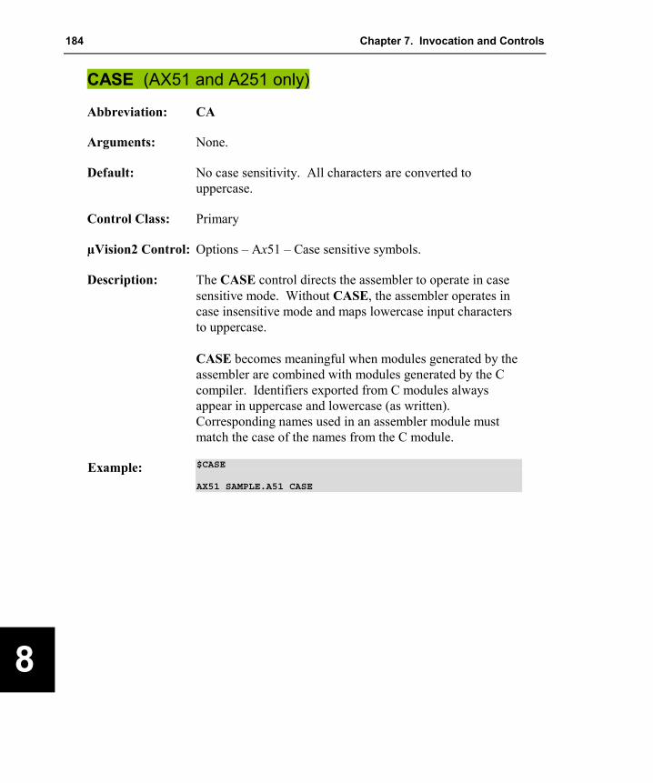
184 Chapter 7. Invocation and Controls
8
CASE (AX51 and A251 only)
Abbreviation: CA
Arguments: None.
Default: No case sensitivity. All characters are converted to uppercase.
Control Class: Primary
µVision2 Control: Options – Ax51 – Case sensitive symbols.
Description: The CASE control directs the assembler to operate in case sensitive mode. Without CASE, the assembler operates in case insensitive mode and maps lowercase input characters to uppercase. CASE becomes meaningful when modules generated by the assembler are combined with modules generated by the C compiler. Identifiers exported from C modules always appear in uppercase and lowercase (as written). Corresponding names used in an assembler module must match the case of the names from the C module.
Example: $CASE
AX51 SAMPLE.A51 CASE
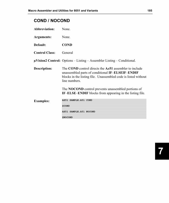
Macro Assembler and Utilities for 8051 and Variants 185
7
COND / NOCOND
Abbreviation: None.
Arguments: None.
Default: COND
Control Class: General
µVision2 Control: Options – Listing – Assembler Listing – Conditional.
Description: The COND control directs the Ax51 assembler to include unassembled parts of conditional IF–ELSEIF–ENDIF blocks in the listing file. Unassembled code is listed without line numbers. The NOCOND control prevents unassembled portions of IF–ELSE–ENDIF blocks from appearing in the listing file.
Examples: AX51 SAMPLE.A51 COND
$COND
AX51 SAMPLE.A51 NOCOND
$NOCOND

186 Chapter 7. Invocation and Controls
8
DATE
Abbreviation: DA
Arguments: A string enclosed within parentheses.
Default: The date obtained from the operating system.
Control Class: Primary
µVision2 Control: Options – Ax51 – Misc controls: enter the control.
Description: The Ax51 assembler includes the current date in the header of each page in the listing file. The DATE control allows you to specify the date string that is included in the header. The string must immediately follow the DATE control and must be enclosed within parentheses. Only the first 8 characters of the date string are used. Additional characters are ignored.
Example: AX51 SAMPLE.A51 DATE(19JAN00)
$DATE(10/28/00)

Macro Assembler and Utilities for 8051 and Variants 187
7
DEBUG
Abbreviation: DB
Arguments: None.
Default: No debugging information is generated.
Control Class: Primary
µVision2 Control: Options – Output – Debug Information
Description: The DEBUG control instructs the Ax51 assembler to include debugging information in the object file. This information is used when testing the program with an emulator or simulator. The DEBUG control also includes line number information for source level debugging. Line number information can be disabled with the NOLINES control.
Examples: A51 SAMPLE.A51 DEBUG
$DEBUG

188 Chapter 7. Invocation and Controls
8
EJECT
Abbreviation: EJ
Arguments: None
Default: None
Control Class: General
µVision2 Control: This control cannot be specified on the command line.
Description: The EJECT control inserts a form feed into the listing file after the line containing the EJECT statement. This control is ignored if NOLIST or NOPRINT was previously specified.
Example: $EJECT

Macro Assembler and Utilities for 8051 and Variants 189
7
ERRORPRINT
Abbreviation: EP
Arguments: An optional filename enclosed within parentheses
Default: No error messages are output to the console.
Control Class: Primary
µVision2 Control: This control is used by µVision2 to get the error output. It should be not specified when you are using the µVision2 IDE.
Description: The ERRORPRINT control directs the Ax51 assembler to output all error messages either to the console (if no filename is specified) or to a specified file.
Examples: AX51 SAMPLE.A51 ERRORPRINT(SAMPLE.ERR)
AX51 SAMPLE2.A51 ERRORPRINT
$EP

190 Chapter 7. Invocation and Controls
8
FIXDRK (A251 only)
Abbreviation: FD
Arguments: None.
Default: Use the INC DRk,#const instruction.
Control Class: Primary
µVision2 Control: Options – A251 – Misc controls: enter the control.
Description: The FIXDRK control instructs the assembler to replace the INC DRk,#const instruction with the ADD DRk,#const instruction. You may require this control because the INC DRk,#const instruction does not work in the Intel 251SB C-step CPU. Check the stepping level or contact your silicon vendor to find out if you need to use this control. If you are using the Intel 8xC251SB device and if you are in doubt about the stepping code, you should apply this control.
Examples: A251 SAMPLE.A51 FIXDRK
$FIXDRK

Macro Assembler and Utilities for 8051 and Variants 191
7
GEN / NOGEN
Abbreviation: GE / NOGE
Arguments: None
Default: NOGEN
Control Class: General
µVision2 Control: Options – Listing – Assembler Listing – Macros.
Description: The GEN control directs the Ax51 assembler to expand or list, in a listing file, all assembly instructions contained in a macro. The NOGEN control prevents the Ax51 assembler from including macro expansion text in the listing file. Only the macro name is listed.
Examples: A51 SAMPLE.A51 GEN
$GEN
A51 SAMPLE.A51 NOGEN
$NOGEN

192 Chapter 7. Invocation and Controls
8
INCDIR
Abbreviation: ID
Arguments: Path specifications for include files enclosed in parentheses.
Default: None.
Control Class: General
µVision2 Control: Options – Ax51 – Include Paths.
Description: The INCDIR control specifies the location of files specified with the INCLUDE control. Multiple path declarations must be separated by semicolon characters (‘;’). A maximum of 5 paths may be specified. When searching for include files, the assembler searches first the current folder, which is typically the folder of the project file.. Then, paths specified by INCDIR are searched.
Example: AX51 SAMPLE.A51 INCDIR(C:\AX51\MYINC;C:\CHIP_DIR)

Macro Assembler and Utilities for 8051 and Variants 193
7
INCLUDE
Abbreviation: IC
Arguments: A filename enclosed within parentheses.
Default: None.
Control Class: General
µVision2 Control: This control cannot be specified on the command line.
Description: The INCLUDE control directs the Ax51 assembler to include the contents of the specified file in the assembly of the program. The include file’s contents are inserted immediately following the INCLUDE control line. INCLUDE files may be nested up to 9 levels deep. The INCLUDE control is usually used to include special function register definition files for x51 derivatives. It is also commonly used to include declarations for external routines, variables, and macros. Files containing assembly language code may also be included.
Example: $INCLUDE (REG51F.INC)
The macro assembler searches the current folder and the folders specified with the INCDIR control for include files. If the specified file cannot be found in this folders, the assembler tries to locate the file in the folder path_of_the_EXE_file\..\ASM\. In a typical installation of the toolchain this is the correct path for the derivate specific include files. (The \C51\BIN\ or \C251\BIN folder contains the macro assembler and the \C51\ASM\ or \C251\ASM\ folder contains the register definition files).
194 Chapter 7. Invocation and Controls
8
INTR2 (A251 only)
Abbreviation: I2
Arguments: None.
Default: The A251 assembler assumes that an interrupt pushes 4 bytes onto the stack: a 24-bit return address and PSW1.
Control Class: General
µVision2 Control: Options – Target – 4 Byte interrupt frame size.
Description: The INTR2 control informs the A251 assembler and the L251 linker/locator that the 251 CPU saves the low order 16 bits of the program counter but does not automatically save PSW1 when entering an interrupt. The INTR2 control does not change any assembler code or instruction encoding. It only informs the linker and debugging tools of the interrupt frame size assumed for interrupt functions. The linker uses this information to check the consistency of the interrupt frame sizes between program modules. If the interrupt frame sizes of the object modules differ, the L251 linker/locator generates a warning message.
Example: A251 SAMPLE.A51 INTR2
$INTR2

Macro Assembler and Utilities for 8051 and Variants 195
7
LIST / NOLIST
Abbreviation: LI / NOLI
Arguments: None
Default: LIST
Control Class: General
µVision2 Control: Options – Ax51 – Misc controls: enter the control.
Description: The LIST control directs the Ax51 assembler to include the program source text in the generated listing file. The NOLIST control prevents subsequent lines of your assembly program from appearing in the generated listing file. If a line that would normally not be listed causes an assembler error, that line will be listed along with the error message.
Examples: AX51 SAMPLE.A51 LI
$LIST
AX51 SAMPLE.A51 NOLIST
$NOLI

196 Chapter 7. Invocation and Controls
8
MOD51, MOD_CONT, MOD_MX51 (AX51 only)
Abbreviation: M51, MC, MX
Arguments: None
Default: MOD51: generate code for classic 8051.
Control Class: Primary
µVision2 Control: Options – Target (mode selection depends on the device).
Description: The MODxxx controls selects the instruction set that is used in the application code.
The MOD51 control is the default setting of AX51 and instructs the assembler to generate code with that uses only the instructions of the classic 8051.
The MOD_MX51 control enables the instruction set extensions for the Philips 80C51MX architecture. If you are using a device with this architecture, at least one module must be translated with this directive. You can intermix code that has be written for the classic 8051 in a project for the Philips 80C51MX.
The MOD_CONT control enables the 24-bit contiguous address mode that is available on some Dallas devices. If you are using this mode, you need to translate all modules with this directive. It is not possible to use code that has been translated for the classic 8051 when you are using this CPU mode.
Examples: AX51 SAMPLE.A51 MOD_MX51AX51 SAMPLE.A51 MOD_COND
$MX ; generate code for Philips 80C51MX architecture$MC ; generate code for Dallas 24-bit contiguous mode

Macro Assembler and Utilities for 8051 and Variants 197
7
MODSRC (A251 only)
Abbreviation: MS
Arguments: None
Default: Generate code for binary mode of the Intel/Temic 251 CPU.
Control Class: Primary
µVision2 Control: Options – Target – CPU Mode.
Description: The MODSRC control instructs the A251 assembler to generate code for the Intel/Temic 251 architecture using the SOURCE mode of this CPU.
Examples: A251 SAMPLE.A51 MODSRC
$MODSRC

198 Chapter 7. Invocation and Controls
8
MPL
Abbreviation: None
Arguments: None
Default: The Macro Processing Language is disabled.
Control Class: Primary.
µVision2 Control: Options – Ax51 – Macro processor – MPL.
Description: The MPL control enables the Macro Processing Language. The MPL language is compatible to the Intel ASM51. Refer to “Chapter 6. Macro Processing Language” on page 151 for more information about the MPL processor.
Examples: A251 SAMPLE.A51 MPL
$MPL
Macro Assembler and Utilities for 8051 and Variants 199
7
NOLINES
Abbreviation: NOLN
Arguments: None.
Default: Line numbers for source level debugging are generated when the DEBUG control is used.
Control Class: Primary
µVision2 Control: Options – Ax51 – Misc controls: enter the control.
Description: The NOLINES control disables the line number information for source level debugging. This control is useful when the Ax51 assembler is used with very old debugging tools and very old emulators.
Examples: A251 SAMPLE.A51 NOLINES
$NOLINES

200 Chapter 7. Invocation and Controls
8
NOMACRO
Abbreviation: None.
Arguments: None.
Default: Standard Macros are fully expanded.
Control Class: Primary
µVision2 Control: Options – Ax51 – Macro processor – Standard.
Description: The NOMACRO control disables the standard macro facility of the Ax51 assembler so that standard macros are not expanded.
Examples: A251 SAMPLE.A51 NOMACRO
$NOMACRO

Macro Assembler and Utilities for 8051 and Variants 201
7
NOMOD51
Abbreviation: NOMO
Arguments: None.
Default: The A51 assembler pre-defines all special function registers of the 8051 CPU. The A251 assembler and the AX51 assembler do not pre-define any CPU special function registers.
Control Class: Primary
µVision2 Control: Options – Ax51 – Special Function Registers – Define 8051 SFR Names.
Description: The NOMOD51 control prevents the A51 assembler from implicitly defining symbols for the default 8051 special function registers. This is necessary when you want to include a definition file to declare symbols for the special function registers of a different 8051 derivative. The A251 assembler and the AX51 assembler support the NOMOD51 control only for source compatibility to the A51. However, the 8051 special function registers are not predefined in A251 or AX51.
Examples: A251 SAMPLE.A51 NOMO
$NOMOD51

202 Chapter 7. Invocation and Controls
8
NOSYMBOLS
Abbreviation: SB / NOSB
Arguments: None
Default: The Ax51 assembler generates a table of all symbols used in and by the assembly program module. This symbol table is included in the generated listing file.
Control Class: Primary
µVision2 Control: Options – Listing – Assembler Listing – Symbols
Description: The NOSYMBOLS control prevents the Ax51 assembler from generating a symbol table in the listing file.
Examples: A251 SAMPLE.A51 SYMBOLS
$SB
A251 SAMPLE.A51 NOSB
$NOSYMBOLS

Macro Assembler and Utilities for 8051 and Variants 203
7
OBJECT / NOOBJECT
Abbreviation: OJ / NOOJ
Arguments: An optional filename enclosed within parentheses.
Default: OBJECT (basename.OBJ)
Control Class: Primary
µVision2 Control: Options – Output – Select Folder for Objects
Description: The OBJECT control specifies that the Ax51 assembler generate an object file. The default name for the object file is basename.OBJ, however, an alternate filename may be specified in parentheses immediately following the OBJECT control statement. The NOOBJECT control prevents the Ax51 assembler from generating an object file.
Examples: A51 SAMPLE.A51 OBJECT (OBJDIR\SAMPLE.OBJ)
OJ(OBJ\SAMPLE.OBJ)
A251 SAMPLE.A51 NOOJ
$NOOBJECT

204 Chapter 7. Invocation and Controls
8
PAGELENGTH, PAGEWIDTH
Abbreviation: PL, PW
Arguments: PAGELENGTH accepts a number between 10 and 65535; PAGEWIDTH accepts a number between 78 and 132 enclosed within parentheses.
Default: PAGELENGTH (60) PAGEWIDTH (120)
µVision2 Control: Options – Listing – Page Length / Page Width
Description: The PAGELENGTH control specifies the number of lines printed per page in the listing file. The number must be a decimal value between 10 and 65535. The default is 60. The PAGEWIDTH control specifies the maximum number of characters in a line in the listing file. Lines that are longer than the specified width are automatically wrapped around to the next line. The default number of characters per line is 120.
Example: A251 SAMPLE.A51 PAGELENGTH(132) PAGEWIDTH (79)
$PL (66)$PW(132)

Macro Assembler and Utilities for 8051 and Variants 205
7
PRINT / NOPRINT
Abbreviation: PR / NOPR
Arguments: An optional filename enclosed within parentheses.
Default: PRINT(basename.LST)
Control Class: Primary
µVision2 Control: Options – Listing – Select Folder for List Files
Description: The PRINT control directs the Ax51 assembler to generate a listing file. The default name for the listing file is basename.LST, however, an alternate filename may be specified in parentheses immediately following the PRINT control statement. The NOPRINT control prevents the Ax51 assembler from generating a listing file.
Examples: A251 SAMPLE.A51 PRINT
A51TESTPRG.A51 PR(TESTPRG1.LST)
$PRINT(LPT1)
AX51 SAMPLE.A51 NOPRINT
$NOPR

206 Chapter 7. Invocation and Controls
8
REGISTERBANK / NOREGISTERBANK
Abbreviation: RB / NORB
Arguments: Register bank numbers separated by commas and enclosed within parentheses. For example, RB (1,2,3).
Default: REGISTERBANK (0)
Control Class: Primary
µVision2 Control: Options – Ax51 – Misc controls: enter the control.
Description: The REGISTERBANK control specifies the register banks used in a source module. This information is stored in the generated object file for further processing by the Lx51 linker/locator. The NOREGISTERBANK control specifies that the Ax51 assembler reserve no memory for the register bank. This is useful for assembler modules that should be used in a generic library. Since this library might be called with any active register bank, you may use the NOREGISTERBANK directive. Thus the program that calls the library module must reserve the register bank that is in use.
Examples: A251 RBUSER.A51 REGISTERBANK(0,1,2)
$RB(0,3)
A51 SAMPLE.A51 NOREGISTERBANK
$NORB
Macro Assembler and Utilities for 8051 and Variants 207
7
REGUSE
Abbreviation: RU
Arguments: Name of a PUBLIC symbol and a register list enclosed in parentheses.
Default: Not applicable.
Control Class: General
µVision2 Control: This control cannot be specified on the command line.
Description: The REGUSE control specifies the registers modified during a function’s execution. This control may be used in combination with the C51 Compiler or C251 Compiler to allow global register optimization for functions written in assembly language. For more information about global register optimization refer to the C Compiler User’s Guide. The REGUSE control may not be specified on the A251 assembler invocation line.
Examples: $REGUSE MYFUNC (ACC, B, R0 - R7)
$REGUSE PROCA (DPL, DPH)
$REGUSE PUTCHAR (R6,R7, CY, ACC)

208 Chapter 7. Invocation and Controls
8
SAVE / RESTORE
Abbreviation: SA / RS
Arguments: None
Default: None
Control Class: General
µVision2 Control: This control cannot be specified on the command line.
Description: The SAVE control stores the current settings of the LIST and GEN controls. Subsequent controls can modify the LIST and GEN settings. This control allows these settings to be saved, altered for a number of program lines, and restored using the RESTORE control. The SAVE control can be nested up to 9 levels deep. The RESTORE control fetches and restores the values of the GEN and LIST controls that were stored by the last SAVE control statement.
Example: ...$SAVE$NOLIST$INCLUDE(SAMPLE.INC)$RESTORE...

Macro Assembler and Utilities for 8051 and Variants 209
7
SYMLIST / NOSYMLIST
Abbreviation: SL/NOSL
Arguments: None.
Default: SYMLIST
Control Class: General
µVision2 Control: Options – Ax51 – Misc controls: enter the control.
Description: The SYMLIST control lists symbol definitions in the symbol table. The NOSYMLIST control prevents the Ax51 assembler from listing symbol definitions in the symbol table. The NOSYMLIST control is useful in special function register definition files or other files where symbols are not desired in the symbol table.
Examples: A251 SAMPLE.A51 NOSYMLIST
$NOSYMLIST$INCLUDE (REG251S.H)$SYMLIST

210 Chapter 7. Invocation and Controls
8
TITLE
Abbreviation: TT
Arguments: A string enclosed within parentheses.
Default: The basename of the source file excluding the extension.
Control Class: General
µVision2 Control: Options – Ax51 – Misc controls: enter the control.
Description: The TITLE control allows you to specify the title to use in the header line of the listing file. The text used for the title must immediately follow the TITLE control and must be enclosed in parentheses. A maximum of 60 characters may be specified for the title. If the TITLE control is not used, the module name specified with the “NAME” directive described on page 124 will be used as title string.
Example: A251 SAMPLE.A51 TITLE(Oven Controller Version 3)
$TT(Race Car Controller)

Macro Assembler and Utilities for 8051 and Variants 211
7
XREF
Abbreviation: XR
Arguments: None.
Default: No error references are listed.
µVision2 Control: Options – Listing – Assembler Listing – Cross Reference
Description: The XREF control directs the Ax51 assembler to generate a cross reference table of the symbols used in the source module. The alphabetized cross reference table will be included in the generated listing file. Refer to “Assembler Listing File Format” on page 385 for an example of a cross reference table.
Example: AX51 SAMPLE.A51 XREF
$XREF

212 Chapter 7. Invocation and Controls
8
Controls for Conditional Assembly The controls for conditional assembly are General controls—they may be specified any number of times in the body of a source file. Conditional assembly may be used to implement different program versions or different memory models with one source file. You may use conditional assembly to maintain one source module that satisfies several applications.
Conditional text blocks are enclosed by IF, ELSEIF, ELSE and ENDIF.
The SET and RESET controls may be used in the invocation line of the assembler to set and reset conditions tested by the IF and ELSEIF controls.
The remaining instructions for conditional assembly are only allowed within the source file and cannot be part of the assembler invocation line.
IF blocks may be nested a maximum of 10 levels deep. If a block is not translated, conditional blocks nested within it are also skipped.
Conditional Assembly Controls Conditional assembly controls allow you to write x51 assembly programs with sections that can be included or excluded from the assembly based on the value of a constant expression. Blocks that are conditionally assembled are enclosed by IF, ELSEIF, ELSE, and ENDIF control statements.
The conditional control statements IF, ELSE, ELSEIF, and ENDIF may be specified only in the source program. They are not allowed on the invocation line. Additionally, these controls may be specified both with and without the leading dollar sign ($).
When prefixed with a dollar sign, the conditional control statements may only access symbols defined by the SET and RESET controls.
When specified without a dollar sign, the conditional control statements may access all symbols except those defined by the SET and RESET controls. These control statements may access parameters in a macro definition.

Macro Assembler and Utilities for 8051 and Variants 213
7
The following table lists the conditional assembly control statements.
Directive Page Description
IF 216 Translate block if condition is true
ELSE 218 Translate block if the condition of a previous IF is false. ELSEIF 217 Translate block if condition is true and a previous IF or ELSEIF is
false. ENDIF 219 Marks end of a block.
RESET 215 Set symbols checked by IF or ELSEIF to false. SET 214 Set symbols checked by IF or ELSEIF to true or to a specified
value.
Predefined Constants (A251 only)
The A251 macro assembler provides you with predefined constants to use in conditional $IF / $ELSEIF controls for more portable assembler modules. The following table lists and describes each one.
Constant Description _ _INTR4_ _ Set to 1 to when A251 assumes 4 byte interrupt frames. If the A251 control
INTR2 is used, the _ _INTR4_ _ symbol is not defined. _ _MODBIN_ _ Set to 1 if the binary mode of 251 CPU is used. If the source mode is
specified with the MODSRC control, the _ _MODBIN_ _ symbol is not defined.
_ _MODSRC_ _ Set to 1 if the source mode of 251 CPU is specified with the MODSRC control. If the binary mode of the 251 CPU is used the _ _MODSRC_ _ symbol is not defined.

214 Chapter 7. Invocation and Controls
8
SET
Abbreviation: None.
Arguments: A list of symbols with optional value assignments separated by commas and enclosed within parentheses. For example: SET (symbol �= number� �, symbol �= number� …�)
Default: None.
Control Class: General
µVision2 Control: Options – Ax51 – Set.
Description: The SET control assigns numeric values to the specified symbols. Symbols that do not include an explicit value assignment are assigned the value 0FFFFh. Symbols that are specified with an equal sign (‘=’) and a numeric value are assigned the specified value. These symbols can be used in IF and ELSEIF control statements for conditional assembly. They are only used for conditional assembly. These symbols are administered separately and do not interfere with other symbols.
Example: A251 SAMPLE.A51 SET(DEBUG1=1, DEBUG2=0, DEBUG3=1)
$SET (TESTCODE = 0)
$SET (DEBUGCODE, PRINTCODE)
Macro Assembler and Utilities for 8051 and Variants 215
7
RESET
Abbreviation: None.
Arguments: A list of symbols separated by commas and enclosed within parentheses. For example: RESET (symbol �, symbol …�)
Default: None
Control Class: General
µVision2 Control: Options – Ax51 – Reset.
Description: The RESET control assigns a value of 0000h to the specified symbols. These symbols may then be used in IF and ELSEIF control statements for conditional assembly. These symbols are only used for conditional assembly. They are administered separately and do not interfere with other symbols.
Example: A251 SAMPLE.A51 RESET(DEBUG1, DEBUG2, DEBUG3)
$RESET (TESTCODE)
$RESET (DEBUGCODE, PRINTCODE)

216 Chapter 7. Invocation and Controls
8
IF
Abbreviation: None
Arguments: A numeric expression
Default: None
Control Class: General
µVision2 Control: This control cannot be specified on the command line.
Description: The IF control begins an IF–ELSE–ENDIF construct that is used for conditional assembly. The specified numeric expression is evaluated and, if it is non–zero (TRUE), the IF block is assembled. If the expression is zero (FALSE), the IF block is not assembled and subsequent blocks of the IF construct are evaluated. IF blocks can be terminated by an ELSE, ELSEIF, or ENDIF control statement.
Example: ...$IF (DEBUG_VAR = 3)...Version_3: MOV DPTR, #TABLE_3...$ ENDIF...

Macro Assembler and Utilities for 8051 and Variants 217
7
ELSEIF
Abbreviation: None
Arguments: A numeric expression.
Default: None
µVision2 Control: This control cannot be specified on the command line.
Description: The ELSEIF control is used to introduce an alternative program block after an IF or ELSEIF control. The ELSEIF block is only assembled if the specified numeric expression is non–zero (TRUE) and if previous IF and ELSEIF conditions in the IF–ELSE–ENDIF construct were FALSE. ELSEIF blocks are terminated by an ELSEIF, ELSE, or ENDIF control.
Example: ...$IF SWITCH = 1 ; Assemble if switch is 1...$ELSEIF SWITCH = 2 ; Assemble if switch is 2...$ELSEIF SWITCH = 3 ; Assemble if switch is 3...$ENDIF...

218 Chapter 7. Invocation and Controls
8
ELSE
Abbreviation: None.
Arguments: None.
Default: None.
Control Class: General
µVision2 Control: This control cannot be specified on the command line.
Description: The ELSE control is used to introduce an alternative program block after an IF or ELSEIF control. The ELSE block is only assembled if previous IF and ELSEIF conditions in the IF–ELSE–ENDIF construct were all FALSE. ELSE blocks are terminated with an ENDIF control.
Example: ...$IF (DEBUG) ; TRUE when DEBUG <> 1...$ELSEIF (TEST)...$ELSE...$ENDIF...

Macro Assembler and Utilities for 8051 and Variants 219
7
ENDIF
Abbreviation: None
Arguments: None
Default: None
Control Class: General
µVision2 Control: This control cannot be specified on the command line.
Description: The ENDIF control terminates an IF–ELSE–ENDIF construct. When the Ax51 assembler encounters an ENDIF control statement, it concludes processing the IF block and resumes assembly at the point of the IF block. Since IF blocks may be nested, this may involve continuing in another IF block. The ENDIF control must be preceded by an IF, ELSEIF, or ELSE control block.
Example: ...$IF TEST...$ENDIF...

220 Chapter 7. Invocation and Controls
8

Macro Assembler and Utilities for 8051 and Variants 221
8
Chapter 8. Error Messages This chapter lists the error messages generated by Ax51. The following sections include a brief description of the possible error messages along with a description of the error and any corrective actions you can take to avoid or eliminate the error.
Fatal errors terminate the assembly and generate a message that is displayed on the console. Non–fatal errors generate a message in the assembly listing file but do not terminate the assembly.
Fatal Errors Fatal errors cause immediate termination of the assembly. These errors usually occur as a result of an invalid command line. Fatal errors are also generated when the assembler cannot access a specified source file or when the macros are nested more than 9 deep.
Fatal errors produce a message that conforms to one of the following formats:
A251 FATAL ERROR – FILE: <file in which the error occurred> LINE: <line in which the error occurred ERROR: <corresponding error message>
A251 TERMINATED.
or
A251 FATAL ERROR –
ERROR: <error message with description> A251 TERMINATED.
where
FILE is the name of an input file that could not be opened.
LINE is the line where the error occurred
ERROR is the fatal error message text explained below.
Fatal Error Messages

222 Chapter 8. Error Messages
B
ATTEMPT TO SHARE FILE
A file is used both for input and output (e.g. list file uses the same name as the source file).
BAD NUMERIC CONSTANT
The numeric argument to the given control is illegal.
CAN’T ATTACH FILE
The given file can’t be opened for read access.
CAN’T CREATE FILE
The given file can’t be opened for write/update access.
CAN’T HAVE GENERAL CONTROL IN INVOCATION LINE
The given control is allowed in $control lines within the source file only (for example the EJECT control). Some controls are allowed only in the source text and not in the command line. Refer to “Chapter 7. Invocation and Controls” on page 179 for more information about the A251 controls.
CAN’T REMOVE FILE
The given temporary file could not be removed for some reason.
CONFLICTING CONTROL
The given control conflicts with an earlier control (for example $NOMOD251 MODSRC).
CONTROL LINE TOO LONG (500)
A $-control line has more than 500 characters.
DISK FILE REQUIRED
The given file does not represent a disk file.
ERRORPRINT– AND LIST–FILE CANNOT BE THE SAME
It is illegal to direct the listing file output and the errorprint output to the console at the same time.
EXPECTED DELIMITER ‘(‘ AFTER CONTROL
The given control requires a brace enclosed argument
EXPECTED DELIMITER ‘)‘ AFTER ARGUMENT
The given control requires a brace enclosed argument
FILE DOES NOT EXIST
The given file does not exist.

Macro Assembler and Utilities for 8051 and Variants 223
8
FILE IS READ ONLY
The given file does not permit write/update access.
FILE WRITE ERROR
The given file could not be written to (check free space)
IDENTIFIER EXPECTED
The given control requires an identifier as it’s argument, for example SET (VAR1=1234H).
ILLEGAL FILE NAME, VOLUME OR DIRECTORY NAME
The name of the file is invalid or designates an invalid file.
INVOCATION LINE TOO LONG
The invocation line is longer than 500 characters.
LIMIT EXCEEDED: BALANCED TEXT LENGTH
The maximum length of a balanced text string is 65000 characters.
LIMIT EXCEEDED: INCLUDE OR MACRO NESTING
The maximum nesting level for MPL-macros is 50. The maximum nesting level of standard macros plus include files is 10.
LIMIT EXCEEDED: MACRO DEFINITION LENGTH
The maximum definition length of a standard macro is 20000 characters. MPL macros are limited to 65000 characters.
LIMIT EXCEEDED: MORE THAN 16000 SYMBOLS
The number of symbols (labels, equ/set symbols, externals, segment-symbols) must not exceed 16000 per source file.
LIMIT EXCEEDED: SOURCE LINE LENGTH (500)
A single source line must not exceed the 500 characters per line limit.
LIMIT EXCEEDED: TOO MANY EXTERNALS (65535)
The number of external symbols must not exceed 65535 per source module.
LIMIT EXCEEDED: TOO MANY EXTERNALS (65535)
The number of externals must not exceed 65535 per source module.
LIMIT EXCEEDED: TOO MANY SEGMENTS (65535)
The number of segments must not exceed 65535 per source module.
NON-NULL ARGUMENT EXPECTED
The argument to the given control must not be null (for example $PRINT()).

224 Chapter 8. Error Messages
B
OUT OF MEMORY
The assembler has run out of memory. Remove unnecessary drivers from your system configuration.
OUT OF RANGE NUMERIC VALUE
The numeric argument to the given control is out of range (for example $PAGEWIDTH(3000)).
UNKNOWN CONTROL
The given control is undefined.
Non–Fatal Errors Non–fatal errors usually occur within the source program and are typically syntax errors. When one of these errors is encountered, the assembler attempts to recover and continue processing the input file. As more errors are encountered, the assembler will produce additional error messages. The error messages that are generated are included in the listing file.
Non–fatal errors produce a message using the following format:
*** ERROR number IN line (file, LINE line): error message
or
*** WARNING number IN line (file, LINE line): warning message
where
number is the error number.
line corresponds to the logical line number in the source file.
file corresponds to the source or include file which contains the error.
LINE corresponds to the physical line number in <file>.
error message is descriptive text and depends on the type of error encountered.
The logical line number in the source file is counted including the lines of all include files and may therefore differ from the physical line number. For that reason, the physical line number and the associated source or include file is also given in error and warning messages.

Macro Assembler and Utilities for 8051 and Variants 225
8
Example 11 MOV R0,# 25 * | 10
*** ----------------------------------------^*** ERROR #4 IN 11 (TEST.A51, LINE 11), ILLEGAL CHARACTER
The caret character (^) is used to indicate the position of the incorrect character or to identify the point at which the error was detected. It is possible that the position indicated is due to a previous error. If a source line contains more than one error, the additional position indicators are displayed on subsequent lines.
The following table lists the non–fatal error messages that are generated by A251. These messages are listed by error number along with the error message and a brief description of possible causes and corrections.
Number Non–Fatal Error Message and Description
1 ILLEGAL CHARACTER IN NUMERIC CONSTANT
This error indicates that an invalid character was found in a numeric constant. Numeric constants must begin with a decimal digit and are delimited by the first non–numeric character (with the exception of the dollar sign). The base of the number decides which characters are valid. • Base 2: 0, 1 and the base indicator B • Base 8: 0–7 and the base indicator O or Q • Base 10: 0–9 and the base indicator D or no indicator • Base 16: 0–9, A–F and the base indicator H • Base 16: 0xhhhh, 0–9, and A–F
2 MISSING STRING TERMINATOR
The ending string terminator was missing. The string was terminated with a carriage return.
3 ILLEGAL CHARACTER
The assembler has detected a character which is not in the set of valid characters for the 51/251 assembler language (for example `).
4 BAD INDIRECT REGISTER IDENTIFIER
This error occurs if combined registers are entered incorrectly; e.g., @R7, @R3, @PC+A, @DPTR+A.
5 ILLEGAL USE OF A RESERVED WORD
This error indicates that a reserved word is used for a label.
6 DEFINITION STATEMENT EXPECTED
The first symbol in the line must be part of a definition. For example: VAR1 EQU 12
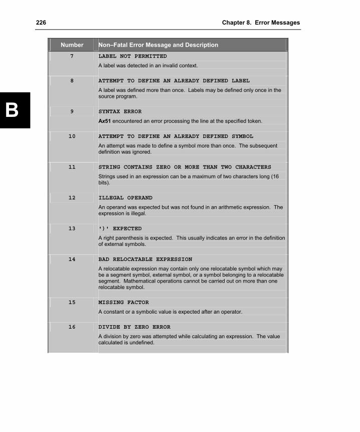
226 Chapter 8. Error Messages
B
Number Non–Fatal Error Message and Description
7 LABEL NOT PERMITTED
A label was detected in an invalid context.
8 ATTEMPT TO DEFINE AN ALREADY DEFINED LABEL
A label was defined more than once. Labels may be defined only once in the source program.
9 SYNTAX ERROR
Ax51 encountered an error processing the line at the specified token.
10 ATTEMPT TO DEFINE AN ALREADY DEFINED SYMBOL
An attempt was made to define a symbol more than once. The subsequent definition was ignored.
11 STRING CONTAINS ZERO OR MORE THAN TWO CHARACTERS
Strings used in an expression can be a maximum of two characters long (16 bits).
12 ILLEGAL OPERAND
An operand was expected but was not found in an arithmetic expression. The expression is illegal.
13 ')' EXPECTED
A right parenthesis is expected. This usually indicates an error in the definition of external symbols.
14 BAD RELOCATABLE EXPRESSION
A relocatable expression may contain only one relocatable symbol which may be a segment symbol, external symbol, or a symbol belonging to a relocatable segment. Mathematical operations cannot be carried out on more than one relocatable symbol.
15 MISSING FACTOR
A constant or a symbolic value is expected after an operator.
16 DIVIDE BY ZERO ERROR
A division by zero was attempted while calculating an expression. The value calculated is undefined.
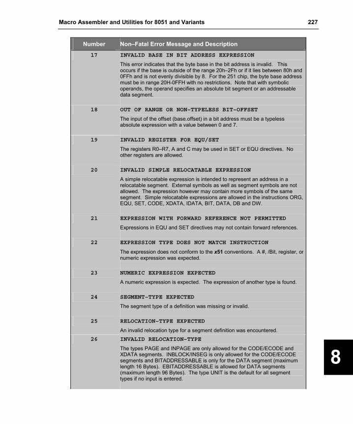
Macro Assembler and Utilities for 8051 and Variants 227
8
Number Non–Fatal Error Message and Description
17 INVALID BASE IN BIT ADDRESS EXPRESSION
This error indicates that the byte base in the bit address is invalid. This occurs if the base is outside of the range 20h–2Fh or if it lies between 80h and 0FFh and is not evenly divisible by 8. For the 251 chip, the byte base address must be in range 20H-0FFH with no restrictions. Note that with symbolic operands, the operand specifies an absolute bit segment or an addressable data segment.
18 OUT OF RANGE OR NON–TYPELESS BIT–OFFSET
The input of the offset (base.offset) in a bit address must be a typeless absolute expression with a value between 0 and 7.
19 INVALID REGISTER FOR EQU/SET
The registers R0–R7, A and C may be used in SET or EQU directives. No other registers are allowed.
20 INVALID SIMPLE RELOCATABLE EXPRESSION
A simple relocatable expression is intended to represent an address in a relocatable segment. External symbols as well as segment symbols are not allowed. The expression however may contain more symbols of the same segment. Simple relocatable expressions are allowed in the instructions ORG, EQU, SET, CODE, XDATA, IDATA, BIT, DATA, DB and DW.
21 EXPRESSION WITH FORWARD REFERENCE NOT PERMITTED
Expressions in EQU and SET directives may not contain forward references.
22 EXPRESSION TYPE DOES NOT MATCH INSTRUCTION
The expression does not conform to the x51 conventions. A #, /Bit, register, or numeric expression was expected.
23 NUMERIC EXPRESSION EXPECTED
A numeric expression is expected. The expression of another type is found.
24 SEGMENT–TYPE EXPECTED
The segment type of a definition was missing or invalid.
25 RELOCATION–TYPE EXPECTED
An invalid relocation type for a segment definition was encountered. 26 INVALID RELOCATION–TYPE
The types PAGE and INPAGE are only allowed for the CODE/ECODE and XDATA segments. INBLOCK/INSEG is only allowed for the CODE/ECODE segments and BITADDRESSABLE is only for the DATA segment (maximum length 16 Bytes). EBITADDRESSABLE is allowed for DATA segments (maximum length 96 Bytes). The type UNIT is the default for all segment types if no input is entered.
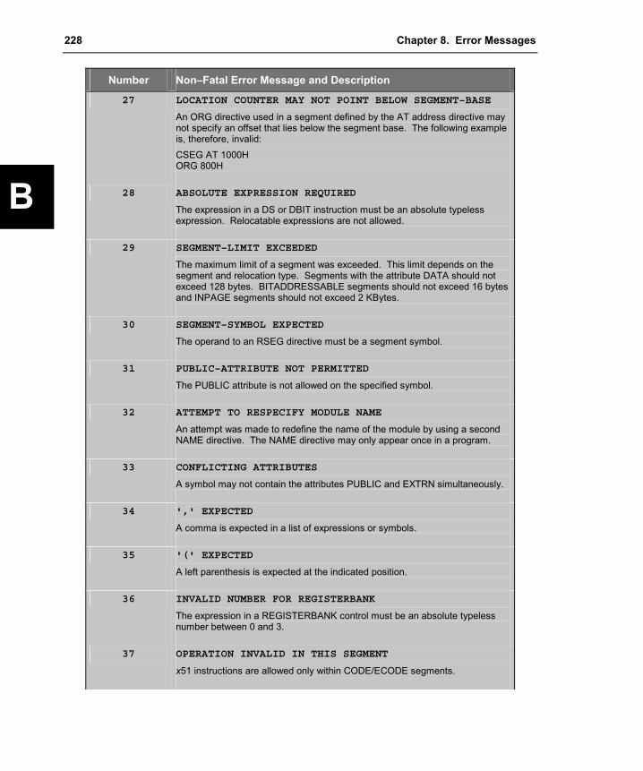
228 Chapter 8. Error Messages
B
Number Non–Fatal Error Message and Description
27 LOCATION COUNTER MAY NOT POINT BELOW SEGMENT–BASE
An ORG directive used in a segment defined by the AT address directive may not specify an offset that lies below the segment base. The following example is, therefore, invalid: CSEG AT 1000H ORG 800H
28 ABSOLUTE EXPRESSION REQUIRED
The expression in a DS or DBIT instruction must be an absolute typeless expression. Relocatable expressions are not allowed.
29 SEGMENT–LIMIT EXCEEDED
The maximum limit of a segment was exceeded. This limit depends on the segment and relocation type. Segments with the attribute DATA should not exceed 128 bytes. BITADDRESSABLE segments should not exceed 16 bytes and INPAGE segments should not exceed 2 KBytes.
30 SEGMENT–SYMBOL EXPECTED
The operand to an RSEG directive must be a segment symbol.
31 PUBLIC–ATTRIBUTE NOT PERMITTED
The PUBLIC attribute is not allowed on the specified symbol.
32 ATTEMPT TO RESPECIFY MODULE NAME
An attempt was made to redefine the name of the module by using a second NAME directive. The NAME directive may only appear once in a program.
33 CONFLICTING ATTRIBUTES
A symbol may not contain the attributes PUBLIC and EXTRN simultaneously.
34 ',' EXPECTED
A comma is expected in a list of expressions or symbols.
35 '(' EXPECTED
A left parenthesis is expected at the indicated position.
36 INVALID NUMBER FOR REGISTERBANK
The expression in a REGISTERBANK control must be an absolute typeless number between 0 and 3.
37 OPERATION INVALID IN THIS SEGMENT
x51 instructions are allowed only within CODE/ECODE segments.

Macro Assembler and Utilities for 8051 and Variants 229
8
Number Non–Fatal Error Message and Description
38 NUMBER OF OPERANDS DOES NOT MATCH INSTRUCTION
Either too few or too many operands were specified for the indicated instruction. The instruction was ignored.
39 REGISTER–OPERAND EXPECTED
A register operand was expected but an operand of another type was found.
40 INVALID REGISTER
The specified register operand does not conform to the x51 conventions.
41 MISSING ‘END’ STATEMENT
The last instruction in a source program must be the END directive. The preceding source is assembled correctly and the object is valid.
42 INTERNAL ERROR (PASS-2), CONTACT TECHNICAL SUPPORT
Occurs if a symbol in pass 2 contains a value different than in pass 1.
43 RESPECIFIED PRIMARY CONTROL, LINE IGNORED
A control was repeated or conflicts with a previous control. The control statement was ignored.
44 MISPLACED PRIMARY CONTROL, LINE IGNORED
A primary control was misplaced. Primary controls may be entered in the invocation line or at the beginning of the source file (as $ instruction). The processing of primary controls in a source file ends when the first non empty/non comment line containing anything but a primary control is processed.
45 UNDEFINED SYMBOL (PASS–2)
The symbol is undefined.
46 CODE/ECODE–ADDRESS EXPECTED
An operand of memory type CODE/ECODE or a typeless expression is expected.
47 XDATA–ADDRESS EXPECTED
An operand of memory type XDATA or a typeless expression is expected.
48 DATA–ADDRESS EXPECTED
An operand of memory type DATA or a typeless expression is expected.
49 IDATA–ADDRESS EXPECTED
An operand of memory type 'IDATA' or a typeless expression is expected.

230 Chapter 8. Error Messages
B
Number Non–Fatal Error Message and Description
50 BIT–ADDRESS EXPECTED
An operand of memory type BIT or a typeless expression is expected.
51 TARGET OUT OF RANGE
The target of a conditional jump instruction is outside of the +127/–128 range or the target of an AJMP or ACALL instruction is outside the 2 KByte memory block.
52 VALUE HAS BEEN TRUNCATED TO 8 BITS
The result of the expression exceeds 255 decimal. Only the 8 low–order bits are used for the byte operand.
53 MISSING 'USING' INFORMATION
The absolute register symbols AR0 through AR7 can be used only if a USING registerbank directive was specified. This error indicates that the USING directive is missing and the assembler cannot assign data addresses to the register symbols.
54 MISPLACED CONDITIONAL CONTROL
An ELSEIF, ELSE, or ENDIF control must be preceded by an IF instruction.
55 BAD CONDITIONAL EXPRESSION
The expression to the IF or ELSEIF control is invalid. These expressions must be absolute and may not contain relocatable symbols. The $IF and $ELSEIF can only access symbols defined with the $SET and $RESET controls. Both IF and ELSEIF allow access to all symbols of the source program.
56 UNBALANCED IF–ENDIF–CONTROLS
Each IF block must be terminated with an ENDIF control. This is also true with skipped nested IF blocks.
57 SAVE STACK UNDERFLOW
A $RESTORE control instruction is then valid only if a $SAVE control was previously given.
58 SAVE STACK OVERFLOW
The context of the GEN, COND, and LIST controls may be stored by the $SAVE control up to a maximum of 9 levels.
59 MACRO REDEFINITION
An attempt was made to define an already defined macro.
60 Not generated by Ax51.
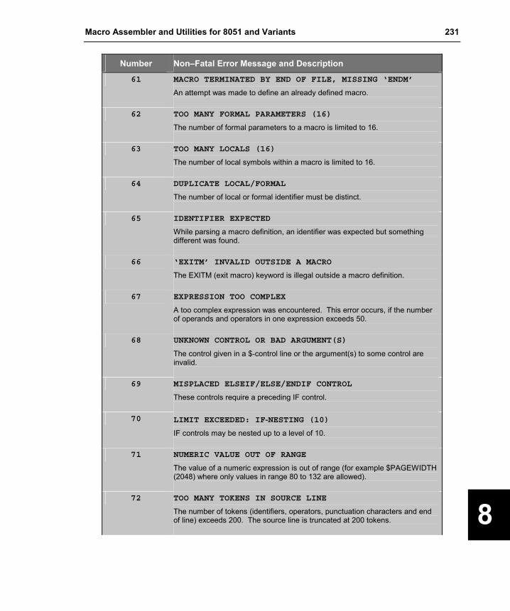
Macro Assembler and Utilities for 8051 and Variants 231
8
Number Non–Fatal Error Message and Description
61 MACRO TERMINATED BY END OF FILE, MISSING ‘ENDM’
An attempt was made to define an already defined macro.
62 TOO MANY FORMAL PARAMETERS (16)
The number of formal parameters to a macro is limited to 16.
63 TOO MANY LOCALS (16)
The number of local symbols within a macro is limited to 16.
64 DUPLICATE LOCAL/FORMAL
The number of local or formal identifier must be distinct.
65 IDENTIFIER EXPECTED
While parsing a macro definition, an identifier was expected but something different was found.
66 ‘EXITM’ INVALID OUTSIDE A MACRO
The EXITM (exit macro) keyword is illegal outside a macro definition.
67 EXPRESSION TOO COMPLEX
A too complex expression was encountered. This error occurs, if the number of operands and operators in one expression exceeds 50.
68 UNKNOWN CONTROL OR BAD ARGUMENT(S)
The control given in a $-control line or the argument(s) to some control are invalid.
69 MISPLACED ELSEIF/ELSE/ENDIF CONTROL
These controls require a preceding IF control.
70 LIMIT EXCEEDED: IF-NESTING (10)
IF controls may be nested up to a level of 10.
71 NUMERIC VALUE OUT OF RANGE
The value of a numeric expression is out of range (for example $PAGEWIDTH (2048) where only values in range 80 to 132 are allowed).
72 TOO MANY TOKENS IN SOURCE LINE
The number of tokens (identifiers, operators, punctuation characters and end of line) exceeds 200. The source line is truncated at 200 tokens.

232 Chapter 8. Error Messages
B
Number Non–Fatal Error Message and Description
72 TOO MANY TOKENS IN SOURCE LINE
The number of tokens (identifiers, operators, punctuation characters and end of line) exceeds 200. The source line is truncated at 200 tokens.
73 TEXT FOUND BEYOND END STATEMENT - IGNORED
Text following the END directive is not processed by the assembler.
74 REGISTER USAGE: UNDEFINED REGISTER NAME
A register name argument given to the REGUSE control does not represent the name of a register.
75 ‘REGISTER USAGE’ REQUIRES A PUBLIC CODE SYMBOL
The register usage value must be assigned to a public symbol, which represents a CODE or ECODE symbol.
76 MULTIPLE REGISTER USES GIVEN TO ONE SYMBOL
The register usage value may be assigned to a symbol or procedure only once.
77 INSTRUCTION NOT AVAILABLE
The given instruction is not available in the current mode of operation.
78 Not generated by Ax51.
79 INVALID ATTRIBUTE
The OVERLAYABLE attribute given in a segment definition is not valid for code and constant segments.
80 INVALID ABSOLUTE BASE/OFFS VALUE
The absolute address given in a segment definition does not conform to the memory type of the segment (for example DATA AT 0x1000).
81 EXPRESSION HAS DIFFERENT MEMORY SPACE
The expression given in a symbol definition statement does not have the memory space required by the directive, for example: VAR1 CODE EXPR where ‘EXPR’ has a memory type other than CODE or NUMBER.
82 LABEL STATEMENT MUST BE WITHIN CODE/ECODE SEGMENT
The LABEL statement is not allowed outside a CODE or ECODE segment.

Macro Assembler and Utilities for 8051 and Variants 233
8
Number Non–Fatal Error Message and Description
83 TYPE INCOMPATIBLE WITH GIVEN MEMORY SPACE
The type given in an external declaration is not compatible to the given memory space. The following examples shows an invalid type since a bit can never reside in code space: EXTRN CODE:BIT (bit0, bit1)
84 OPERATOR REQUIRES A CODE/ECODE ADDRESS
The type override operators NEAR and FAR cannot be applied to addresses with memory type other than CODE and ECODE.
85 INVALID OPERAND TYPE
An expression contains invalid typed operands to some operator, for example addition/unary minus on bit-type operands.
86 PROCEDURES CAN’T BE NESTED
A251 does not support nested procedures.
87 UNCLOSED PROCEDURE
A251 detected an unclosed procedure after scanning the source file.
88 VALUE HAS BEEN TRUNCATED TO 16 BITS
The displacement value given in a register expression (WRn+disp16, DRk+disp16) has been truncated to 16 bits.
89 Not generated by Ax51.
90 ‘FAR’ RETURN IN ‘NEAR’ PROCEDURE
The return far instruction (ERET) was encountered in a procedure of type NEAR (the code may not work).
91 TYPE MISMATCH
The operand type of an instruction operand does not match the requested type of the instruction, for example: MOV WR10,Byte_Memory_Operand. ; Word/Byte mismatch Use a type override to avoid the warning as shown: MOV WR10,WORD Byte_Memory_Operand
92, 93 Not generated by Ax51.
94 VALUE DOES NOT MATCH INSTRUCTION
The short value given in a INC/DEC Rn,#short is not one of 1,2,4.

234 Chapter 8. Error Messages
B
Number Non–Fatal Error Message and Description
95 ILLEGAL MEMORY CLASS SPECIFIER
The memory class specifier in a segment definition statement does not correspond to one of the predefined memory class names (CODE, ECODE, BIT, EBIT ...).
96 ACCESS TO MISALIGNED ADDRESS
A word instruction accesses a misaligned (odd) address. This warning is generated only if the $WORDALIGN control was given.
97 ‘FAR’ REFERENCE TO ‘NEAR’ LABEL
An ECALL/AJMP instruction to some label of type NEAR has been detected.
98 ‘NEAR’ REFERENCE TO ‘FAR’ LABEL
An ACALL/AJMP/SJMP or conditional jump instruction to some label of type FAR has been detected.
99 'PROC' NAME REQUIRED
Ax51 expects the name of the procedure.
100 ILLEGAL CONSTANT VALUE
The constant value is illegal or has an illegal format.
101 TRAP INSTRUCTION IS RESERVED FOR DEBUGGING TOOLS
The TRAP instruction should be used for program debugging only.
102 PONTENTIAL ADDRESS OVERLAP
There is a potential address overlay in your program that is caused by ORG statements.
103 <user error text>
This error is generated by the C preprocessor #error directive or the __ERROR__ directive.
104 - 149 Not generated by Ax51.
150 PREMATURE END OF FILE ENCOUNTERED
The MPL macro processor encountered the end of the source file while parsing a macro definition.
151 <name>: IDENTIFIER EXPECTED
The macro or function given by <name> in the error message expected an identifier but found something else.

Macro Assembler and Utilities for 8051 and Variants 235
8
Number Non–Fatal Error Message and Description
152 MPL FUNCTION <name>: <character> EXPECTED
The MPL function <name> expected a specific character in the input stream but found some other character.
153 <name>: UNBALANCED PARENTHESIS
While scanning balanced text, the macro processor expected a ‘)’ character, but found some other character.
154 EXPECTED <identifier>
The macro processor expected some specific identifier (for example ELSE) but found some other text.
155 Not generated by Ax51.
156 FUNCTION ‘MATCH’: ILLEGAL CALL PATTERN
The call pattern to the MPL function match must be a formal parameter followed by a delimiter followed by another formal parameter.
157 FUNCTION ‘EXIT’ IN BAD CONTEXT
The EXIT function must not appear outside a macro expansion, %REPEAT or %WHILE.
158 ILLEGAL METACHARACTER <character>
The metacharacter may not be @, (, ), *, TAB, EOL, A-Z,a-z, 0-9, _ and ?.
159 CALL PATTERN - DELIMITER <delimiter> NOT FOUND
The actual parameters in a macro call do not match the call pattern defined in the macro definition of that macro.
160 CALL TO UNDEFINED MACRO <macroname>
An attempt to activate an undefined macro has been encountered .
161 ERROR-161Not generated by Ax51.
162 INVALID DIGIT ‘character’ IN NUMBER
An ill formed number has been encountered. For numbers, the rules are equal to the numbers in the assembler language with the exception of $ signs, which are not supported within the MPL.
163 UNCLOSED STRING OR CHARACTER CONSTANT
A string or character constant is terminated by an end of line character instead of the closing character.

236 Chapter 8. Error Messages
B
Number Non–Fatal Error Message and Description
164 INVALID STRING OR CHARACTER CONSTANT
A string or character constant may contain one or two characters.
165 EVAL: UNKNOWN EXPRESSION IDENTIFIER
An MPL expression contains an unknown identifier.
166 <token>: INVALID EXPRESSION TOKEN
An MPL expression contains a token which neither represents an operator nor an operand.
167 <function>: DIV/MOD BY ZERO
The evaluation of an expression within the MPL function <function> yields a division or modulus by zero.
168 EVAL: SYNTAX ERROR IN EXPRESSION
An expression is followed by one or more erroneous tokens.
169 CAN’T OPEN FILE <name of file>
The file given in an $INCLUDE control cannot be opened.
170 <name of file>: IS NOT A DISK FILE
An attempt was made to open a file which is not a disk file (for example $INCLUDE (CON).
171 ERROR IN INCLUDE DIRECTIVE
The argument to the INCLUDE control must be the brace enclosed name of the file, for example $INCLUDE (REG251.INC).
172 CAN’T REDEFINE PREDEFINED MACRO ‘SET’
The .predefined %SET macro can’t be redefined.
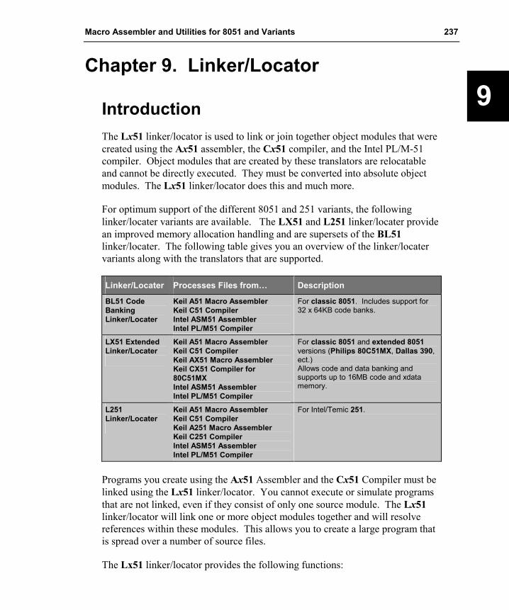
Macro Assembler and Utilities for 8051 and Variants 237
9
Chapter 9. Linker/Locator
Introduction The Lx51 linker/locator is used to link or join together object modules that were created using the Ax51 assembler, the Cx51 compiler, and the Intel PL/M-51 compiler. Object modules that are created by these translators are relocatable and cannot be directly executed. They must be converted into absolute object modules. The Lx51 linker/locator does this and much more.
For optimum support of the different 8051 and 251 variants, the following linker/locater variants are available. The LX51 and L251 linker/locater provide an improved memory allocation handling and are supersets of the BL51 linker/locater. The following table gives you an overview of the linker/locater variants along with the translators that are supported.
Linker/Locater Processes Files from… Description
BL51 Code Banking Linker/Locater
Keil A51 Macro Assembler Keil C51 Compiler Intel ASM51 Assembler Intel PL/M51 Compiler
For classic 8051. Includes support for 32 x 64KB code banks.
LX51 Extended Linker/Locater
Keil A51 Macro Assembler Keil C51 Compiler Keil AX51 Macro Assembler Keil CX51 Compiler for 80C51MX Intel ASM51 Assembler Intel PL/M51 Compiler
For classic 8051 and extended 8051 versions (Philips 80C51MX, Dallas 390, ect.) Allows code and data banking and supports up to 16MB code and xdata memory.
L251 Linker/Locater
Keil A51 Macro Assembler Keil C51 Compiler Keil A251 Macro Assembler Keil C251 Compiler Intel ASM51 Assembler Intel PL/M51 Compiler
For Intel/Temic 251.
Programs you create using the Ax51 Assembler and the Cx51 Compiler must be linked using the Lx51 linker/locator. You cannot execute or simulate programs that are not linked, even if they consist of only one source module. The Lx51 linker/locator will link one or more object modules together and will resolve references within these modules. This allows you to create a large program that is spread over a number of source files.
The Lx51 linker/locator provides the following functions:

238 Chapter 9. Linker/Locator
9
�� Combines several program modules into one module, automatically incorporating modules from the library files
�� Combines relocatable partial segments of the same segment name into a single segment
�� Allocates and manipulates the necessary memory for the segments with which all relocatable and absolute segments are processed
�� Analyzes the program structure and manipulates the data memory using overlay techniques
�� Resolves external and public symbols
�� Defines absolute addresses and computes the addresses of relocatable segments
�� Produces an absolute object file that contains the entire program
�� Produces a listing file that contains information about the Link/Locate procedure, the program symbols, and the cross reference of public and external symbol names
�� Detects errors found in the invocation line or during the Link/Locate run.
�� Supports programs that are larger than 64 Kbytes and applications that are using a Real-Time Multitasking Operating System (RTX51, RTX251, ect.).
All of these operations are described in detail in the remaining sections of this chapter.
“Overview” on page 239 provides you with a summary of the features and capabilities of the BL51 linker/locator. This chapter introduces the concepts of what a linker is and does.
“Linking Programs” on page 247 describes how to invoke the linker from the command line. The command-line arguments are discussed, and examples are provided.
“Locating Programs to Physical Memory” on page 253 shows how to specify the physical memory available in the target hardware and how to locate segments to specific addresses.
“Data Overlaying” on page 257 explains how the Lx51 linker/locater creates a call tree for segment overlaying of local variables and discusses how to modify this call tree for applications that use indirect program calls.

Macro Assembler and Utilities for 8051 and Variants 239
9
“Tips and Tricks for Program Locating” on page 265 shows you several additional features of the Lx51 linker/locater. These features allow you to create in-system programmable applications, to determine the addresses of segments, to use the C251 memory class NCONST without ROM in segment 0, or to locate several segments within a 2KB block.
“Bank Switching” on page 268 describes what bank switching is and how it is implemented by the Lx51 linker/locator. This chapter also shows how to make applications that are larger than 64 KBytes work with code banking.
“Control Summary” on page 280 lists the command-line controls by category and provides you with descriptions of each, along with examples.
“Error Messages” on page 335 lists the errors that you may encounter when you use the Lx51 linker/locator.
Overview The Lx51 linker/locator takes the object files and library files you specify and generates a absolute object file. Absolute object files can be loaded into debugging tools or may be converted into Intel HEX files for PROM programming by OHx51 Object-Hex Converter.
NOTE Banked object files generated by the BL51 linker/locater must be converted by the OC51 Banked Object File Converter into absolute object files (one for each bank) before they can be converted into Intel HEX files by the OH51 Object-Hex Converter.
While processing object and library files, the Lx51 linker/locator performs the following operations.
Combining Program Modules The object modules that the Lx51 linker/locator combines are processed in the order in which they are specified on the command line. The Lx51 linker/locator processes the contents of object modules created with the Ax51 assembler or the Cx51 compiler. Library files, however, contain a number of different object modules; and, only the object modules in the library file that specifically resolve external references are processed by the Lx51 linker/locator.

240 Chapter 9. Linker/Locator
9
Segment Naming Conventions Objects generated by the Cx51 and Intel PL/M-51 compilers are stored in segments, which are units of code or data memory. A segment may be relocatable or may be absolute. Each relocatable segment has a type and a name. This section describes the conventions used for naming these segments.
Segment names include a module_name. The module_name is the name of the source file in which the object is declared and excludes the drive letter, path specification, and file extension. In order to accommodate a wide variety of existing software and hardware tools, all segment names are converted and stored in uppercase.
Each segment name has a prefix (or in case of PL/M-51 a postfix) that corresponds to the memory type used for the segment. The prefix is enclosed in question marks (?). The following is a list of the standard segment name prefixes.
Segment Prefix Memory Class Description
?PR? CODE Executable program code
?CO? CONST Constant data in program memory
?ED? EDATA EDATA memory for near variables ?FD? HDATA HDATA memory for far variables ?XD? XDATA XDATA memory
?DT? DATA DATA memory
?ID? IDATA IDATA memory
?BI? BIT Bit data in internal data memory
?BA? DATA Bit-addressable data in internal data memory
?PD? XDATA Paged data in XDATA memory For detailed information about the segment naming conventions refer
to the Cx51 Compiler User’s Guide.
Combining Segments A segment is a code or data block that is created by the compiler or assembler from your source code. There are two basic types of segments: absolute and relocatable. Absolute segments reside in a fixed memory location. They cannot be moved by the linker. Absolute segments do not have a segment name and will not be combined with other segments. Relocatable segments have a name and a type (as well as other attributes shown in the table below). Relocatable segments with the same name but from different object modules are considered parts of the

Macro Assembler and Utilities for 8051 and Variants 241
9
same segment and are called partial segments. The linker/locator combines these partial relocatable segments.
The following table lists the segment attributes that are used to determine how to link, combine, and locate code or data in the segment.
Attribute Description
Name Each relocatable segment has a name that is used when combining relocatable segments from different program modules. Absolute segments do not have names.
Memory Class The memory class identifies the address space to which the segment belongs. For BL51 the type can be CODE, XDATA, DATA, IDATA, or BIT. LX51 and L251 support in addition CONST, EBIT, ECONST, EDATA, HDATA, HCODE, HCONST, and user-define memory classes.
Relocation Type The relocation type specifies the relocation operations that can be performed by the linker/locator. Valid relocation types are AT address, BITADDRESSABLE, INBLOCK, INPAGE, INSEG, OFFS offset, and OVERLAYABLE.
Alignment Type The alginment type specifies the alignment operations that can be performed by the linker/locator. Valid alignment types are BIT, BYTE, WORD, DWORD, PAGE, BLOCK, and SEG.
Length The length attribute specifies the length of the segment. Base Address The base address specifies the first assigned address of the segment.
For absolute segments, the address is assigned by the assembler. For relocatable segments, the address is assigned by the linker/locator.
While processing your program modules, the linker/locator produces a table or map of all segments. The table contains name, type, location method, length, and base address of each segment. This table aids in combining partial relocatable segments. All partial segments having the same name are combined by the linker/locator into one single relocatable segment. The linker/locator uses the following rules when combining partial segments.
�� All partial segments that share a common name must have the same memory class. An error occurs if the types do not correspond.
�� The length of the combined segments must not exceed the length of the physical memory area.
�� The location method for each of the combined partial segments must correspond.
Absolute segments are not combined with other absolute segments, they are copied directly to the output file.

242 Chapter 9. Linker/Locator
9
Locating Segments After the linker/locator combines partial segments it must determine a physical address for them. The linker/locator processes each memory class separately. Refer to “Memory Classes and Memory Layout” on page 27 for a discussion of the different memory class and the physical address ranges.
After the linker/locator combines partial segments, it must determine a physical address for them. The linker/locator places different segments in each of these memory areas. The memory is allocated in the following order:
1. Register Banks and segments with an absolute address.
2. Segments specified in Lx51 segment allocation controls.
3. Segments with the relocation type BITADDRESSABLE and other BIT segments.
4. All other segments with the memory class DATA.
5. Segments with the memory class IDATA, EDATA and NCONST.
6. Segments with the memory class XDATA.
7. Segments with the memory class CODE and the relocation type INBLOCK.
8. Other Segments with the memory class CODE and CONST.
9. Segments with the memory classes ECODE, HCONST, and HDATA.
Overlaying Data Memory The stack addressing of the x51 CPU is slower compared to accessing fixed, absolute memory locations. For this reason, local variables and function arguments of C and PL/M-51 routines are stored at fixed memory locations rather than on the stack. By using techniques to overlay the parameters and local variables of C and PL/M-51 functions, the linker/locator attempts to maximize the amount of available space.
NOTE The Cx51 compiler supports also reentrant functions where the parameters and

Macro Assembler and Utilities for 8051 and Variants 243
9
automatic variables are store on the CPU stack of a simulate stack. For detailed information refer to the Cx51 User’s Guides.
To accomplish overlaying, the linker/locator analyzes all references or calls between the various functions. Using this information, the linker/locator can determine precisely which data and bit segments can be overlaid.
You may use the OVERLAY and NOOVERLAY control to enable or disable data overlaying. The OVERLAY control is the default and allows for very compact data areas. Use the NOOVERLAY control to disable the segment overlay function.
Resolving External References External symbols reference addresses in other modules. A declared external symbol must be resolved with a public symbol of the same name. Therefore, for each external symbol, a public symbol must exist in another module.
The linker/locator builds a table of all public and external symbols that it encounters. External references are resolved with public references as long as the names match and the symbol attributes correspond.
The linker/locator reports an error if the symbol types of an external and public symbol do not correspond. The linker/locator also reports an error if no public symbol is found for an external reference.
The absolute addresses of the public symbols are resolved after the location of the segments is determined.
Absolute Address Calculation After the segments are assigned fixed memory locations and external and public references are processed, the linker/locator calculates the absolute addresses of the relocatable addresses and external addresses. Symbolic debugging information is also updated to reflect the new addresses.

244 Chapter 9. Linker/Locator
9
Generating an Absolute Object File The linker/locator generates the executable target program in absolute object module format. The generated object module may contain debugging information if the linker/locator is so directed. This information facilitates symbolic debugging and testing. You may use the linker controls to suppress debugging information in the object file.
The output file generated by the linker/locator may be loaded into the µVision2 debugger, in-circuit emulators, or may be translated into an Intel HEX file for use with an EPROM programmer. The following table provides an overview of the output format and the processing method for the different linker/locater variants.
Linker/Locater Output Format Description
BL51 Linker/Locater
Extended Intel OMF51 or Banked OMF51
Intel OMF51 is the standard format for programming the 8051 and supported by virtually all emulator vendors. Extensions in this format provide symbolic information. For banked applications the BL51 Linker/Locater generates a banked OMF51 file that can be converted with the OC51 Object File Converter into standard OMF51 files. The OC51 step is also required to convert the file into an Intel HEX file.
LX51 Extended Linker/Locater
Keil OMFx51 The Keil OMFx51 format supports of up to 16MB code and xdata memory. This format is required for extended 8051 versions (Philips 80C51MX, Dallas 390, ect.). Check with your emulator vendor if this format is supported.
L251 Linker/Locater
Intel OMF251 Intel OMF251 is the standard format for programming the 251 and supported by all 251 emulator vendors.
Generating a Listing File The linker/locator generates a listing file that lists information about each step in the link and locate process. This file also contains information about the symbols and segments involved in the linkage. In addition, the following information may be found in the listing file:
�� The filenames and other parameters specified on the command line.
�� Filenames and module names of all processed modules.
�� A memory allocation table, which contains the location of the segments, the segment type, the location method, and the segment name. This table may be suppressed by specifying the NOMAP control.

Macro Assembler and Utilities for 8051 and Variants 245
9
�� The overlay map which shows the structure of the finished program and lists address information for the local data and bit segments of a function. The overlay map also lists all code segments for which OVERLAYABLE segments exist. You may suppress the overlay map by specifying the NOMAP control.
�� LX51 and L251 provide a list of all PUBLIC symbols within a program.
�� A list of all errors in segments and symbols. The error causes are listed at the end of the listing file.
�� A list of all unresolved external symbols. An external symbol is unresolved if no corresponding public symbol exists in another input file. Each reference to an unresolved external symbol is listed in an error message at the end of the listing file.
�� A symbol table, which contains the symbol information from the input files. This information consists of the names of the MODULES, SYMBOLS, PUBLICS, and LINES. You may selectively suppress the symbolic information with linker controls.
�� An alphabetically sorted cross reference report of all PUBLIC and EXTERN symbols in which the memory type and the module names that contain a reference to that symbol are displayed.
�� Errors detected during the execution of the linker/locator are displayed on the screen as well as at the end of the listing file. Refer to “Error Messages” on page 335 for a summary of the linker/locator errors and causes.
Bank Switching The classic 8051 directly supports a maximum of 64 KBytes of code space. The Lx51 linker/locator allows 8051 programs to be created that are larger than 64 KBytes by using a technique known as code banking or bank switching. Bank switching involves using extra hardware to select one of a number of code banks all of which will reside at a common physical address.
For example, your hardware design may include a ROM mapped from address 0000h to 7FFFh (known as the common area) and four 32K ROM blocks mapped from code address 8000h to 0FFFFh (known as the code bank area). The following figure shows the memory structure.
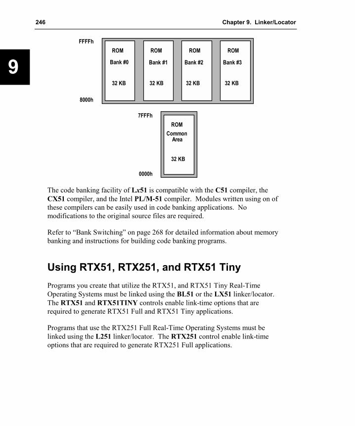
246 Chapter 9. Linker/Locator
9
ROM ROM
ROM
ROM ROM
Common Area
Bank #0 Bank #1 Bank #2 Bank #3
32 KB 32 KB 32 KB
32 KB
32 KB
0000h
7FFFh
FFFFh
8000h
The code banking facility of Lx51 is compatible with the C51 compiler, the CX51 compiler, and the Intel PL/M-51 compiler. Modules written using on of these compilers can be easily used in code banking applications. No modifications to the original source files are required.
Refer to “Bank Switching” on page 268 for detailed information about memory banking and instructions for building code banking programs.
Using RTX51, RTX251, and RTX51 Tiny Programs you create that utilize the RTX51, and RTX51 Tiny Real-Time Operating Systems must be linked using the BL51 or the LX51 linker/locator. The RTX51 and RTX51TINY controls enable link-time options that are required to generate RTX51 Full and RTX51 Tiny applications.
Programs that use the RTX251 Full Real-Time Operating Systems must be linked using the L251 linker/locator. The RTX251 control enable link-time options that are required to generate RTX251 Full applications.

Macro Assembler and Utilities for 8051 and Variants 247
9
Linking Programs The Lx51 linker/locater is invoked by typing the program name at the Windows command prompt. On this command line, you must include the name of the assembler source file to be translated, as well as any other necessary assembler controls required to translate your source file. The format for the Lx51 command line is:
BL51 ����inputlist���� ����TO outputfile���� ����controls����
LX51 ����inputlist���� ����TO outputfile���� ����controls����
L251 ����inputlist���� ����TO outputfile���� ����controls����
or BL51 @commandfileLX51 @commandfileL251 @commandfile
where
inputlist is a list of the object files, separated by commas, for the linker/locator to include in the outputfile. The inputlist can contain files from Ax51, Cx51, PL/M-51 and library files. For library files you may force the inclusion of modules by specifying the module names in parentheses. The format of the inputlist is described below.
outputfile is the name of the absolute object file that the linker/locator creates. If no outputfile is specified on the command line, the first filename in the input list is used. The basename of the outputfile is also the default name for the map file.
controls are commands and parameters that control the operation of the Lx51 linker/locator.
commandfile is the name of a command input file that may contain an inputlist, outputfile, and controls. The text in a commandfile has the same format as the standard command line and is produced by any standard ASCII text editor. Newline characters and comments a commandfile are ignored. Lx51 interprets the first filename preceded by an at sign (@) as a commandfile.

248 Chapter 9. Linker/Locator
9
The inputlist uses the following general format:
filename �(modulename �, …�)� �, …�
where
filename is the name of an object file created by Ax51, Cx51, or Intel PL/M-51 or a library file created by the LIBx51 library manager. The filename must be specified with its file extension. Object files use the extension .OBJ. Library files use the extension .LIB.
modulename is the name of an object module in the library file. The modulename may only be used after the name of a library file. The modulenames must be specified in parentheses after the filename. Multiple modulenames may be separated by commas.
Command Line Examples The following examples are proper command lines for the Lx51 linker/locator.
BL51 C:\MYDIR\PROG.OBJ TO C:\MYDIR\PROG.ABS
In this example, only the input file, C:\MYDIR\PROG.OBJ, is processed and the absolute object file generated is stored in the output file C:\MYDIR\PROG.ABS.
LX51 SAMPLE1.OBJ, SAMPLE2.OBJ, SAMPLE3.OBJ TO SAMPLE.ABS
In this example, the files SAMPLE1.OBJ, SAMPLE2.OBJ, and SAMPLE3.OBJ are linked and absolute object file that is generated is stored in the file SAMPLE.ABS.
L251 PROG1.OBJ, PROG2.OBJ, UTILITY.LIB
In this example, unresolved external symbols are resolved with the public symbols from the library file UTILITY.LIB. The modules required from the library are linked automatically. Modules from the library that are not referenced are not included in the generated absolute object file.
BL51 PROG1.OBJ, PROG2.OBJ, UTILITY.LIB (FPMUL, FPDIV)
In this example, unresolved external symbols are resolved with the public symbols from the library file UTILITY.LIB. The modules required from the library are linked automatically. In addition, the FPMUL and FPDIV modules

Macro Assembler and Utilities for 8051 and Variants 249
9
are included whether they are needed or not. Other modules from the library that are not referenced are not included in the generated absolute object file.
LX51 @PROJECT.LIN
Content of the file PROJECT.LIN: PROG1.OBJ, /* Program Module 1 */PROG2.OBJ, // program module 2UTILITY.LIB (FPMUL, FPDIV) ; include always FPMUL and FPDIV
This is example is the same as the example before, but uses a command input file that includes comments.
Control Linker Input with µVision2 The C and assembler source files that are part of a µVision2 project are translated when you build your application. The object files generated are then supplied as linker input file by the µVision2 build process. However you may also include object and library files as part of a µVision2 project in the same way as you include source files. You may set additional linker options for a file or file group using the Options – Properties dialog. For detailed information refer to the Getting Started and Creating Applications User’s Guide.
ERRORLEVEL After linking, the Lx51 linker/locator sets the ERRORLEVEL to indicate the status of the linking process. The Lx51 linker/locater and the other utilities generate the same ERRORLEVEL values as the Ax51 macro assembler. Refer to “ERRORLEVEL” on page 181 for more information.
Output File The Lx51 linker/locator creates an output file using the input object files that you specify on the command line. The output file is an absolute object file that may be loaded into debugging tools like the µVision2 Debugger or may be converted into a Intel HEX for PROM programming.

250 Chapter 9. Linker/Locator
9
Linker/Locater Controls Controls for the Lx51 linker/locater may be entered after the output file specification. Multiple controls must be separated by at least one space character ( ). Each control may be entered only once on the command line. If a control is entered twice, the Lx51 linker/locator reports an error.
The following table lists all Lx51 linker/locator controls and a brief description. The controls of the BL51 linker/locater are listed in the first table. The controls of the extended LX51 linker/locater and L251 linker/locater are listed in the second table. LX51 and L251 provide the same sets of controls.
The “Control Summary” on page 280 explains the command-line controls in detail. Refer to page number provided in the tables for quick reference to descriptions and examples for each control.
NOTE Underlined characters denote the abbreviation for the particular control.

Macro Assembler and Utilities for 8051 and Variants 251
9
BL51 Controls
Controls Page Description BANKAREA 307 Specifies the address range where the code banks are located. BANKx 308 Specifies the start address and segments for code banks. BIT 309 Locates and orders BIT segments. CODE 313 Locates and orders CODE segments. DATA 314 Locates and orders DATA segments. DISABLEWARNING 282 Disables specified warning messages. IBANKING 298 Generate bank switch code for Infineon TV TEXT devices. IDATA 315 Locates and orders IDATA segments. IXREF 283 Includes a cross reference report in the listing file. NAME 298 Specifies a module name for the object file. NOAJMP 300 Generate bank switch code without AJMP instructions. NODEBUGLINES 300 Excludes line number information from the object file. NODEBUGPUBLICS 300 Excludes public symbol information from the object file. NODEBUGSYMBOLS 300 Excludes local symbol information from the object file. NODEFAULTLIBRARY 327 Excludes modules from the run-time libraries. NOINDIRECTCALL 302 Do not generate bank switch code for indirectly called functions. NOJMPTAB 303 Do not generate bank switch code. NOLINES 285 Excludes line number information from the listing file. NOMAP 286 Excludes memory map information from the listing file. NOOVERLAY 328 Prevents overlaying or overlapping local bit and data segments. NOPRINT 290 Disables generation of a listing file. NOPUBLICS 287 Excludes public symbol information from the listing file. NOSORTSIZE 316 Disable size sorting for segments before allocating the memory. NOSYMBOLS 288 Excludes local symbol information from the listing file. OVERLAY 329 Modifies call tree for data overlaying of local data & bit segments. PAGELENGTH 289 Sets maximum number of lines in each page of listing file. PAGEWIDTH 289 Sets maximum number of characters in each line of listing file. PDATA 316 Specifies the starting address for PDATA segments. PRECEDE 318 Locates segments that precede others in the DATA memory. PRINT 290 Specifies the name of the listing file. RAMSIZE 319 Specifies the size of the on-chip data memory. RECURSIONS 331 Allows analyze of the call tree of complex recursive applications. REGFILE 331 Specifies the register usage information file generated by Lx51. RTX51 333 Includes support for the RTX-51 full real-time kernel. RTX51TINY 333 Includes support for the RTX-51 tiny real-time kernel. SPEEDOVL 334 Ignore during overlay analysis references from constant segments. STACK 324 Locates and orders STACK segments. XDATA 325 Locates and orders XDATA segments.

252 Chapter 9. Linker/Locator
9
LX51 and L251 Controls
Controls Page Description
ASSIGN 297 Defines public symbols on the command line.
BANKAREA 307 Specifies the address range where the code banks are located.
CLASSES 311 Specifies a physical address range for segments in a memory class.
DISABLEWARNING 282 Disables specified warning messages.
IXREF 283 Includes a cross reference report in the listing file.
NAME 298 Specifies a module name for the object file.
NOAJMP 300 Generate bank switch code without AJMP instructions.
NOCOMMENTS 284 Excludes comment information from listing file and the object file.
NODEFAULTLIBRARY 327 Excludes modules from the run-time libraries.
NOINDIRECTCALL 302 Do not generate bank switch code for indirectly called functions.
NOLINES 285 Excludes line number information from listing file and object file.
NOMAP 286 Excludes memory map information from the listing file.
NOOVERLAY 328 Prevents overlaying or overlapping local bit and data segments.
NOPRINT 290 Disables generation of a listing file.
NOPUBLICS 287 Excludes public symbol information from the listing and object file.
NOSYMBOLS 288 Excludes local symbol information from the listing file.
NOSORTSIZE 316 Disable size sorting for segments before allocating the memory.
NOTYPE 302 Excludes type information from the listing file and the object file.
OBJECTCONTROLS 305 Excludes specific debugging information from the object file.
OVERLAY 329 Modifies call tree for data overlaying of local data & bit segments.
PAGELENGTH 289 Sets maximum number of lines in each page of listing file.
PAGEWIDTH 289 Sets maximum number of characters in each line of listing file.
PRINT 290 Specifies the name of the listing file.
PRINTCONTROLS 291 Excludes specific debugging information from the listing file.
PURGE 292 Excludes all debugging information from the listing and object file.
RECURSIONS 331 Allows analyze the call tree of complex recursive applications.
REGFILE 331 Specifies the register usage information file generated by Lx51.
RESERVE 320 Reserves memory and prevent Lx51 from using memory areas. RTX251 333 Includes support for the RTX-251 full real-time kernel.
RTX51 333 Includes support for the RTX-51 full real-time kernel.
RTX51TINY 333 Includes support for the RTX-51 tiny real-time kernel.
SEGMENTS 321 Defines physical memory addresses and orders for segments.
SEGSIZE 323 Specifies memory space used by a segment.
WARNINGLEVEL 293 Controls the types and severity of warnings generated.

Macro Assembler and Utilities for 8051 and Variants 253
9
Locating Programs to Physical Memory This section describes with examples how you locate your application into the physical memory space for the different x51 variants. Refer to “Segment and Memory Location Controls” on page 306 for a detailed description of the linker/locater controls used in the examples below.
The linker/locator determines the physical memory range for relocateable segments based on the memory class that is assigned to the segment. Refer to “Memory Classes and Memory Layout” on page 27 for more information. However, it is also possible to specify a fixed address for a segment using linker/locater controls.
Classic 8051 The classic 8051 provides three different memory areas: on-chip RAM that covers the DATA, BIT and IDATA memory, XDATA memory, and CODE memory. The “Classic 8051 Memory Layout” is shown on page 29.
Classic 8051 without Code Banking
The following examples illustrate how to setup the linker/locater. For the BL51 linker/locater the physical memory is defined with the RAMSIZE, XDATA and CODE control. For the LX51 linker/locater the CLASSES control is used to specify the available physical memory.
The following example assumes the following memory areas.
Memory Type Address Range Used by
ON-CHIP RAM D:0 – D:0x7F (128 Bytes) registers, bits, variables, ect.
XDATA RAM X:0 – X:0x7FFF, X:0xF800 – X:0xFFFF space for variables.
CODE ROM C:0 – C:0x7FFF program code and constant area.
To specify this memory layout BL51 should be invoked with as follows:
BL51 PROG.OBJ XDATA (0-0x7FFF, 0xF800-0xFFFF) CODE (0-0x7FFF) RAMSIZE(128)
You may also you the LX51 linker/locater. The CLASSES directive should have the following settings:

254 Chapter 9. Linker/Locator
9
LX51 PROG.OBJ CLASSES (IDATA (D:0-D:0x7F),XDATA (X:0-X:0x7FFF, X:0xF800-X:0xFFFF),CODE (C:0-C:0x7FFF))
NOTE You need not to define the address range for the memory classes DATA and BIT since the LX51 default setting already covers the correct physical address range.
Classic 8051 with Code Banking
The following example uses classic 8051 with a code banking hardware. This hardware has the following memory resources:
Memory Type Address Range Used by
ON-CHIP RAM I:0 – I:0xFF (256 Bytes) registers, bits, variables, ect.
XDATA RAM X:0 – X:0xEFFF space for variables.
CODE ROM C:0 – C:0x7FFF (common area) B0:0x8000 – B3:0xFFFF (four banks)
program code and constant area.
Parts of your program will be located into banks using BANKx in the inputlist portion of the Lx51 linker/locater command-line. Refer to “Bank Switching” on page 268 for more information. In addition you must specify the size of the common area and the other memory resources of your hardware. For this memory layout, the BL51 linker/locater should be invoked with as follows:
BL51 BANK0 {A.OBJ}, BANK1 {B.OBJ}, BANK2 {C.OBJ}, BANK3 {D.OBJ}XDATA (0-0xEFFF) BANKAREA (0x8000 – 0xFFFF) RAMSIZE(256)
The LX51 linker/locater needs to be invoked as follows:
LX51 BANK0 {A.OBJ}, BANK1 {B.OBJ}, BANK2 {C.OBJ}, BANK3 {D.OBJ}CLASSES (IDATA (I:0-I:0xFF), XDATA (X:0-X:0xEFFF),
CODE (C:0-C:0xFFFF)) BANKAREA (0x8000-0xFFFF)
Extended 8051 Variants Some extended 8051 variants expand the external data and program memory to up to 16MB. The additional memory space is addressed with the memory classes HDATA and HCONST. The “Extended 8051 Memory Layout” is shown on page 31. Only the LX51 linker/locater supports this expanded memory space. The following example shows assumes the following memory areas.

Macro Assembler and Utilities for 8051 and Variants 255
9
Memory Type Address Range Used by
ON-CHIP RAM D:0 – D:0xFF (256 Bytes) registers, bits, variables.
XDATA RAM X:0 – X:0x1FFFF (128 KB) space for variables.
CODE ROM C:0 – C:0xFFFFF (1 MB) program code and constant area.
To specify this memory layout LX51 should be invoked with the following CLASSES directive.
LX51 MYPROG.OBJ CLASSES (HDATA (X:0 – X:0x1FFFF),HCONST (C:0 – C:0xFFFFF))
NOTE You need not to define the address range for the memory classes DATA, IDATA, BIT, CODE, CONST, and XDATA since the LX51 default already covers the correct physical address ranges for these memory classes.
The memory classes HDATA and HCONST are used for constants or variables only. Program code is located into the expanded program memory with the same code banking mechanism as described above under “Classic 8051 with Code Banking”. A command line example that locates also program code into the expanded program memory will look as follows:
LX51 BANK0 {A.OBJ}, BANK1 {B.OBJ}, BANK2 {C.OBJ}, BANK3 {D.OBJ}CLASSES (IDATA (I:0-I:0xFF), XDATA (X:0-X:0xEFFF),
HDATA (X:0-X:0x1FFFF), HCONST (C:0-C:0xFFFFF)CODE (C:0-C:0xFFFF)) BANKAREA (0x8000-0xFFFF)
There are several Keil Application Notes available that shows how to create programs for extended 8051 devices. Check www.keil.com or the Keil development tools CD-ROM for Keil Application Notes that explain how to setup the tools for extended 8051 devices.
Philips 80C51MX The Philips 80C51MX has a linear 16MB address space that includes the standard 8051 memory areas DATA/IDATA, CODE, and XDATA. In addition both the external data space and the program space can be up to 8 MB. The “80C51MX Memory Layout” is shown on page 33. The LX51 linker/locater is used for the Philips 80C51MX microcontroller family. The following example shows assumes the following memory areas.
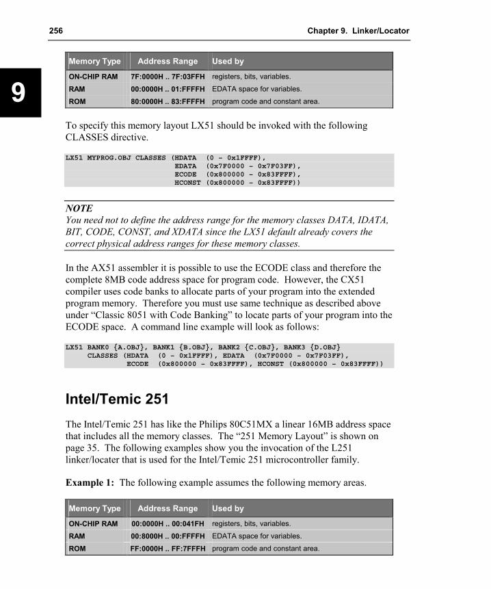
256 Chapter 9. Linker/Locator
9
Memory Type Address Range Used by
ON-CHIP RAM 7F:0000H .. 7F:03FFH registers, bits, variables.
RAM 00:0000H .. 01:FFFFH EDATA space for variables.
ROM 80:0000H .. 83:FFFFH program code and constant area.
To specify this memory layout LX51 should be invoked with the following CLASSES directive.
LX51 MYPROG.OBJ CLASSES (HDATA (0 – 0x1FFFF),EDATA (0x7F0000 – 0x7F03FF),ECODE (0x800000 – 0x83FFFF),HCONST (0x800000 – 0x83FFFF))
NOTE You need not to define the address range for the memory classes DATA, IDATA, BIT, CODE, CONST, and XDATA since the LX51 default already covers the correct physical address ranges for these memory classes.
In the AX51 assembler it is possible to use the ECODE class and therefore the complete 8MB code address space for program code. However, the CX51 compiler uses code banks to allocate parts of your program into the extended program memory. Therefore you must use same technique as described above under “Classic 8051 with Code Banking” to locate parts of your program into the ECODE space. A command line example will look as follows:
LX51 BANK0 {A.OBJ}, BANK1 {B.OBJ}, BANK2 {C.OBJ}, BANK3 {D.OBJ}CLASSES (HDATA (0 – 0x1FFFF), EDATA (0x7F0000 – 0x7F03FF),
ECODE (0x800000 – 0x83FFFF), HCONST (0x800000 – 0x83FFFF))
Intel/Temic 251 The Intel/Temic 251 has like the Philips 80C51MX a linear 16MB address space that includes all the memory classes. The “251 Memory Layout” is shown on page 35. The following examples show you the invocation of the L251 linker/locater that is used for the Intel/Temic 251 microcontroller family.
Example 1: The following example assumes the following memory areas.
Memory Type Address Range Used by
ON-CHIP RAM 00:0000H .. 00:041FH registers, bits, variables.
RAM 00:8000H .. 00:FFFFH EDATA space for variables.
ROM FF:0000H .. FF:7FFFH program code and constant area.

Macro Assembler and Utilities for 8051 and Variants 257
9
To specify this memory layout L251 should be invoked with the following CLASSES directive.
L251 MYPROG.OBJ CLASSES (EDATA (0 – 0x41F, 0x8000 – 0xFFFF),CODE (0xFF0000 – 0xFF7FFF),CONST (0xFF0000 – 0xFF7FFF))
NOTES You need not to define the address range for the memory classes DATA, IDATA, BIT and EBIT since the L251 default already covers the correct physical address ranges for these memory classes. This example assumes that the memory classes XDATA, HDATA, HCONST, HCODE, and NCONST are not used in your application.
Example 2: In addition to the example above, the next system contains a third RAM for the memory class XDATA. In addition the ROM space is increased.
Memory Type Address Range Used by
ON-CHIP RAM 00:0000H .. 00:041FH registers, bits, variables.
ROM 00:0420H .. 00:7FFFH NCONST space.
RAM 00:8000H .. 01:7FFFH EDATA/HDATA space for variables.
ROM FE:0000H .. FF:FFFFH program code and constant area.
To specify this memory layout L251 should be invoked with the following CLASSES directive.
L251 MYPROG.OBJ CLASSES (EDATA (0 – 0x41F, 0x8000 – 0xFFFF),NCONST (0x420 – 0x7FFF),HDATA (0x8000-0x1FFFF),HCONST (0xFE0000 – 0xFFFFFF),ECODE (0xFE0000 – 0xFFFFFF))
NOTE You need not to define the address range for the memory classes DATA, IDATA, BIT, EBIT, CODE, CONST, and XDATA since the L251 default already covers the correct physical address ranges for these memory classes.
Data Overlaying Because of the limited amount of stack space available on the x51, local variables and function arguments of C and PL/M-51 routines are stored at fixed

258 Chapter 9. Linker/Locator
9
memory locations rather than on the stack. Normally, the Lx51 linker/locator analyses the program structure of your application, creates a call tree and overlays the data segments that contain local variables and function arguments.
This technique usually works very well and provides the same efficient use of memory than a conventional stack frame would. Therefore this technique is also known as compiled-time stack since the stack layout is fixed during the Compiler and Linker run. However, in certain situations, this can be undesirable. You may use the NOOVERLAY control to disable overlay analysis and data overlaying. Refer to “NOOVERLAY” on page 328 for more information about this control.
By default, the Lx51 linker/locator overlays the memory areas for local variables and function arguments with the same memory areas of other functions, provided that the functions do no call each other. Therefore the Lx51 linker/locator analyses the program structure and creates a function call tree.
The local data and bit segments that belong to a function are determined by their segment names. The local data and bit segments of a function are overlaid with other function’s data and bit segments under the following conditions:
�� No call references may exist between the functions. The Lx51 linker/locator considers direct calls between functions, as well as calls via other functions.
�� The functions may be invoked by only one program event: main or interrupt. It is not possible to overlay data areas if a function is called by an interrupt and during the main program. The same is true when the function is called by several interrupts that might be nested.
�� The segment definitions must conform to the rules described below.
NOTE Typically, the Lx51 linker/locator generates overlay information that is accurate. However, in some instances the default analysis of the call tree is ineffective or incorrect. This occurs with indirectly called functions through function pointers and functions that are called by both the main program and an interrupt function.
Program and Data Segments of Functions For correct data overlaying the Lx51 linker/locater must know the function code and the local variable space that belongs to this function. The program and data segments that belong together are determined by standard segment naming

Macro Assembler and Utilities for 8051 and Variants 259
9
convention used by the Cx51 compiler and PL/M-51 compiler. Therefore, segments used in assembler programs should be constructed according to the following rules.
Segment Content Cx51 Segment Name PL/M-51 Segment Name
Program CODE ?PR?functionname?modulename ?modulename?PR Local BIT space ?BI?functionname?modulename ?modulename?BI
Local DATA space ?DT?functionname?modulename ?modulename?DT Local IDATA space ?ID?functionname?modulename —
Local XDATA space ?XD?functionname?modulename —
Local PDATA space ?PD?functionname?modulename —
Local EDATA space ?ED?functionname?modulename —
Local EBIT space ?EB?functionname?modulename —
Local HDATA space ?HD?functionname?modulename — ?PR?, ?BI?, ?DT?, ?XD?, ?ID?, ?PD?, ?ED?, ?EB?, and ?HD? is derived from the memory class.
In addition each bit and data segment must have the relocation type OVERLAYABLE.
The Cx51 compiler and PL/M-51 compiler define automatically local data segments according to these rules. However, if you use overlayable segments in your assembly modules, you must follow these naming conventions. Refer to “SEGMENT” on page 102 for information on how to declare segments.
Example for Segment declaration in assembly language:
?PR?func1?module1 SEGMENT CODE ; segment for func1 code?DT?func1?module1 SEGMENT DATA OVERLAYABLE ; data segment belongs to func1
RSEG ?DT?func1?module1func1_var: DS 10 ; space for local variables in func1
RSEG ?PR?func1?module1func1: MOV func1_var,A
RET
More information can be found in the Keil Application Note 149: Data Overlaying and Code Banking with Assembler Modules that is available on www.keil.com or the Keil development tools CD-ROM.
Using the Overlay Control In most cases, the Lx51 data overlay algorithm works correct and does not require any adjustments. However, in some instances the overlay algorithm cannot determine the real structure of your program and you must adjust the function call tree with the OVERLAY control. This is the case when your

260 Chapter 9. Linker/Locator
9
program uses function pointers or contains virtual program jumps as it is the case in the scheduler of a real-time operating system.
NOTE The Lx51 linker/locater recognizes correctly the program structure and the call tree of applications that are using the RTXx51 real-time operating system. You need not to use the OVERLAY control to specify the task functions of the RTXx51 application, since this is automatically performed by the Lx51 linker/locater.
The OVERLAY control allows you to change the call references used by the Lx51 linker/locator during the overlay analysis. Using the OVERLAY control is easy when you know the structure of your program. The program structure or call tree is reflected in the segments listed in the OVERLAY MAP of the listing file created by the Lx51 linker/locater.
The following application examples show situations where the OVERLAY control is required to correct the call tree. In general, a modification of the references (calls) is required in the following cases:
�� When a pointer to a function is passed or returned as function argument.
�� When a pointer to a function is contained in initialized variables.
�� When your program includes a real-time operating system.
Disable Data Overlaying
If you are in doubt about whether certain segments should be overlaid or not, you may disable overlaying of those segments. Segment overlaying can be disabled at Cx51 compiler level or with the OVERLAY control at the Lx51 linker/locator command line as follows:
�� You can invoke the Lx51 linker/locator with the NOOVERLAY option to disable data overlaying for the entire application.
�� The Lx51 linker/locator control OVERLAY (sfname ! *) disables data overlaying for the function specified by sfname.
�� C code that is translated with the Cx51 compiler directive OPTIMIZE (1) does not use the relocation type OVERLAYABLE. Therefore the local data segments of this code portions cannot be overlaid.
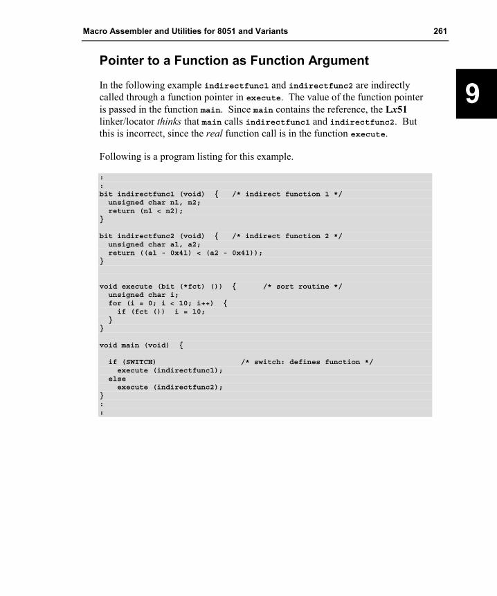
Macro Assembler and Utilities for 8051 and Variants 261
9
Pointer to a Function as Function Argument
In the following example indirectfunc1 and indirectfunc2 are indirectly called through a function pointer in execute. The value of the function pointer is passed in the function main. Since main contains the reference, the Lx51 linker/locator thinks that main calls indirectfunc1 and indirectfunc2. But this is incorrect, since the real function call is in the function execute.
Following is a program listing for this example.
::bit indirectfunc1 (void) { /* indirect function 1 */unsigned char n1, n2;return (n1 < n2);
}
bit indirectfunc2 (void) { /* indirect function 2 */unsigned char a1, a2;return ((a1 - 0x41) < (a2 - 0x41));
}
void execute (bit (*fct) ()) { /* sort routine */unsigned char i;for (i = 0; i < 10; i++) {if (fct ()) i = 10;
}}
void main (void) {
if (SWITCH) /* switch: defines function */execute (indirectfunc1);
elseexecute (indirectfunc2);
}::

262 Chapter 9. Linker/Locator
9
The following listing file shows the overlay map for the program before making adjustments with the OVERLAY control.
OVERLAY MAP OF MODULE: OVL1 (OVL1)
SEGMENT BIT-GROUP DATA-GROUP+--> CALLING SEGMENT START LENGTH START LENGTH
------------------------------------------------------------------?C_C51STARTUP ----- ----- ----- -----+--> ?PR?MAIN?OVL1
?PR?MAIN?OVL1 ----- ----- ----- -----+--> ?PR?INDIRECTFUNC1?OVL1+--> ?PR?EXECUTE?OVL1+--> ?PR?INDIRECTFUNC2?OVL1
?PR?INDIRECTFUNC1?OVL1 ----- ----- 0008H 0002H
?PR?EXECUTE?OVL1 ----- ----- 0008H 0004H
?PR?INDIRECTFUNC2?OVL1 ----- ----- 0008H 0002H
The entry for ?PR?MAIN?OVL1 shows a call to ?PR?INDIRECTFUNC1?OVL1, ?PR?EXECUTE?OVL1, and ?PR?INDIRECTFUNC2?OVL1. However, only the function execute is called from main. The other references are results from using the function pointer fct, which is passed to execute. The function call to indirectfunc1 and indirectfunc2 takes place in execute, not in main where the functions are referenced.
In this situation, the linker/locator cannot locate the actual function calls. Therefore, the Lx51 linker/locator incorrectly overlays the local segments of the functions execute, indirectfunc1, and indirectfunc2. This might result in a data overwrites of the variables i and fct.
You can use the OVERLAY control to correct the function call tree as it seen by the linker. For this example, you must remove the references from main to indirectfunc1 and indirectfunc2. Do this with main ~ (indirectfunc1, indirectfunc2). Then, add the actual function call from execute to indirectfunc1 and indirectfunc2 with executed ! (indirectfunc1, indirectfunc2). The following shows the complete linker invocation line for this example.
Lx51 OVL1.OBJ OVERLAY (main ~ (indirectfunc1, indirectfunc2),execute ! (indirectfunc1, indirectfunc2))

Macro Assembler and Utilities for 8051 and Variants 263
9
With this Lx51 invocation the overlay map shows the correct references.
OVERLAY MAP OF MODULE: OVL1 (OVL1)
SEGMENT BIT-GROUP DATA-GROUP+--> CALLING SEGMENT START LENGTH START LENGTH
----------------------------------------------------------------?C_C51STARTUP ----- ----- ----- -----+--> ?PR?MAIN?OVL1
?PR?MAIN?OVL1 ----- ----- ----- -----+--> ?PR?EXECUTE?OVL1
?PR?EXECUTE?OVL1 ----- ----- 0008H 0004H+--> ?PR?INDIRECTFUNC1?OVL1+--> ?PR?INDIRECTFUNC2?OVL1
?PR?INDIRECTFUNC1?OVL1 ----- ----- 000CH 0002H
?PR?INDIRECTFUNC2?OVL1 ----- ----- 000CH 0002H
Pointer to a Function in Arrays or Tables
Another typical scenario is an array that contains a pointer to a function. This is typical for applications with function tables. In the following example, func1 and func2 are called indirectly by main but the entry points are stored as constant values in the table functab. This table is located in the segment ?CO?modulname. Therefore, the ?CO?OVL2 segment contains references to func1 and func2.
In reality, however, the calls are executed from the main function. But, the Lx51 linker/locator assumes that func1 and func2 are recursive called, because in func1 and func2 constant strings are used. These constants strings are also stored in the segment ?CO?OVL2. The result is that the Lx51 linker/locator reports warnings which indicate recursive calls from the segment ?CO?OVL2 to func1 and func2.
The following listing shows part of the OVL2 program.
.
.
.void func1 (void) {unsigned char i; /* function 1 */
for (i = 0; i < 10; i++) printf ("THIS IS FUNCTION1\n");}
void func2 (void) { /* function 2 */unsigned char i;

264 Chapter 9. Linker/Locator
9
for (i = 0; i < 10; i++) printf ("THIS IS FUNCTION2\n");}
code void (*functab []) () = {func1, func2}; /* function table */
void main (void) {(*functab [P1 & 0x01]) ();
}...
The Lx51 linker/locater generates typically warnings when you generate programs that contain a table with pointer to functions. Although the program can be executed correct in this example above, the references should be adjusted to the real calls. In the real application the functions func1 and func2 are called by the main function.
If you are using the BL51 linker/locater in the default configuration you need to delete the references from the code segment that contains the tables with ?CO?OVL2 ~ (func1, func2). Then you need to add the calls from main to func1 and func2 with main ! (func1, func2):
BL51 OVL2.OBJ OVERLAY (?CO?OVL2~(func1, func2), main!(func1, func2))
The SPEEDOVL control of BL51 ignores all references from constant segments to program code. This is also the operation mode of LX51 and L251. Therefore you need only to add the calls from main to func1 and func2 with main ! (func1, func2):
BL51 OVL2.OBJ OVERLAY (main ! (func1, func2)) SPEEDOVL
The LX51 and L251 linker/locater always ignores the references from constant segments to program code and requires only to add the function calls:
LX51 OVL2.OBJ OVERLAY (main ! (func1, func2))
After this correction the memory usage of your application is typically more efficient and the overlay map shows a call tree that matches your application. Also the linker/locater does not generate any warning messages.
OVERLAY MAP OF MODULE: OVL2 (OVL2)
SEGMENT BIT-GROUP DATA-GROUP+--> CALLING SEGMENT START LENGTH START LENGTH
-----------------------------------------------------------------?C_C51STARTUP ----- ----- ----- -----+--> ?PR?MAIN?OVL2
?PR?MAIN?OVL2 ----- ----- ----- -----

Macro Assembler and Utilities for 8051 and Variants 265
9
+--> ?PR?FUNC1?OVL2+--> ?PR?FUNC2?OVL2
?PR?FUNC1?OVL2 ----- ----- 0008H 0001H+--> ?PR?PRINTF?PRINTF
?PR?PRINTF?PRINTF ----- ----- 0009H 0014H+--> ?PR?PUTCHAR?PUTCHAR
?PR?FUNC2?OVL2 ----- ----- 0008H 0001H+--> ?PR?PRINTF?PRINTF
Tips and Tricks for Program Locating The Lx51 linker/locator supports several techniques that are required in for special tasks, for example in-system Flash programming or systems that use a RAM section for constants. The following section provides examples that show the usage of the Lx51 linker/locater in such situations.
Locate Segments with Wildcards The Lx51 linker/locater allows in the segment controls wildcards for specifying the segment name. For example you may use such segment name specifications to locate all segments within one module into one 2KB block. In this way you can use the ACALL and AJMP instructions for function calls within this module.
BL51 myfile.obj CODE (?PR?*?myfile (0x1000))
LX51 myfile.obj SEGMENTS (?PR?*?myfile (C:0x1000))
Special ROM Handling (LX51 & L251 only) The LX51 and L251 linker/locater provide the memory class SROM that is used to handle segments or memory classes that are to be stored in ROM, but copied for execution into RAM areas. This is useful for:
�� In-system Flash programming when the Flash ROM contains also the flash programming code. With standard Flash devices it is impossible to fetch program code from the while other parts of the device are erased or programmed. The Keil Application Note 139: “In-system Flash Programming with 8051 and 251” that is available on www.keil.com or the Keil development tools CD-ROM contains a program example.
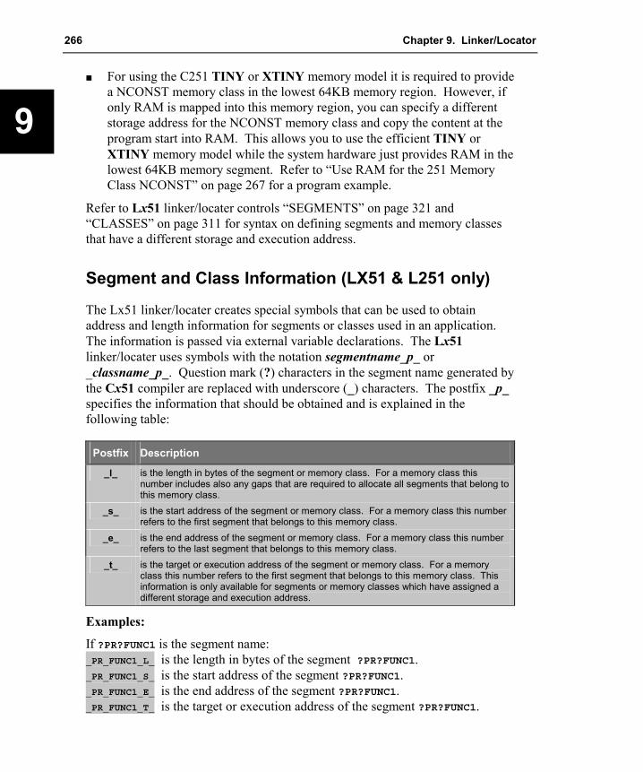
266 Chapter 9. Linker/Locator
9
�� For using the C251 TINY or XTINY memory model it is required to provide a NCONST memory class in the lowest 64KB memory region. However, if only RAM is mapped into this memory region, you can specify a different storage address for the NCONST memory class and copy the content at the program start into RAM. This allows you to use the efficient TINY or XTINY memory model while the system hardware just provides RAM in the lowest 64KB memory segment. Refer to “Use RAM for the 251 Memory Class NCONST” on page 267 for a program example.
Refer to Lx51 linker/locater controls “SEGMENTS” on page 321 and “CLASSES” on page 311 for syntax on defining segments and memory classes that have a different storage and execution address.
Segment and Class Information (LX51 & L251 only)
The Lx51 linker/locater creates special symbols that can be used to obtain address and length information for segments or classes used in an application. The information is passed via external variable declarations. The Lx51 linker/locater uses symbols with the notation segmentname_p_ or _classname_p_. Question mark (?) characters in the segment name generated by the Cx51 compiler are replaced with underscore (_) characters. The postfix _p_ specifies the information that should be obtained and is explained in the following table:
Postfix Description
_l_ is the length in bytes of the segment or memory class. For a memory class this number includes also any gaps that are required to allocate all segments that belong to this memory class.
_s_ is the start address of the segment or memory class. For a memory class this number refers to the first segment that belongs to this memory class.
_e_ is the end address of the segment or memory class. For a memory class this number refers to the last segment that belongs to this memory class.
_t_ is the target or execution address of the segment or memory class. For a memory class this number refers to the first segment that belongs to this memory class. This information is only available for segments or memory classes which have assigned a different storage and execution address.
Examples:
If ?PR?FUNC1 is the segment name: _PR_FUNC1_L_ is the length in bytes of the segment ?PR?FUNC1. _PR_FUNC1_S_ is the start address of the segment ?PR?FUNC1. _PR_FUNC1_E_ is the end address of the segment ?PR?FUNC1. _PR_FUNC1_T_ is the target or execution address of the segment ?PR?FUNC1.

Macro Assembler and Utilities for 8051 and Variants 267
9
If NCONST is the memory class name: _NCONST_L_ is the length in bytes of the memory class NCONST. _NCONST_S_ is the start address of the memory class NCONST. _NCONST_E_ is the end address of the memory class NCONST. _NCONST_T_ is the target or execution address of the memory class NCONST.
You may access this information in Cx51 applications as shown in the following program example:
extern char _PR_FUNC1_L_;
unsigned int get_length (void) {return ((unsigned int) &_PR_FUNC1_L_); // length of segment ?PR?FUNC1
}
The file SROM.H contains macro definitions for accessing segment and class information. Refer to the Keil Application Note 139: “In-system Flash Programming with 8051 and 251” for more information.
Use RAM for the 251 Memory Class NCONST
The C251 compiler memory model TINY or XTINY requires a NCONST memory class in the lowest 64KB memory region. If your hardware provides only RAM in this memory area, you may use the SROM memory class to store the constants somewhere in the 16MB memory space and you may copy the content of the NCONST memory class into a RAM in the lowest 64KB memory. This is shown in the following program example. Refer to the “CLASSES” control on page 311 for more information. #include <string.h>
extern char huge _NCONST_S_;extern char huge _NCONST_T_;extern char near _NCONST_L_;
const char text [] = "This text is accessed in the NCONST memory class";
void main (void) {fmemcpy (&_NCONST_T_, &_NCONST_S_, (unsigned int)&_NCONST_L_);:
}
The C251 compiler and L251 linker/locater is invoke as follows: C251 SAMPLE.C XTINY DEBUG
L251 SAMPLE.C CLASSES (NCONST (0x2000-0x4000)[]), SROM (0xFE0000-0xFEFFFF)
268 Chapter 9. Linker/Locator
9
Bank Switching The Lx51 linker/locator manages and allows you to locate program code in up to 32 code banks and one common code area. The common code area is always available for all the code banks. The common code area and other aspects of the code banking are described below.
Common Code Area The common code area can be accessed by all banks. This area usually includes routines and constant data that must always be accessible; for example, interrupt and reset vectors, interrupt routines, string constants, bank switching routines, etc. The following code sections must always be located in the common area:
��Reset and Interrupt Vectors: reset and interrupt jump entries must remain in the common area, since the code bank selected by the x51 program is not known at the time of the CPU reset or interrupt. The Lx51 linker/locator, therefore, locates absolute code segments in the common area in each case.
��Code Constants: constant values (strings, tables, etc.) which are defined in the code area must be stored in the common area unless you guarantee that the code bank containing the constant data is selected at the time they are accessed by program code. You can relocate these segments in code banks by means of control statements.
��Interrupt Functions: generated using the Cx51 compiler must always be located in the common area. However, interrupt functions can call functions in other code banks. The Lx51 linker/locator produces a warning when an attempt is made to locate a Cx51 interrupt function in a code bank.
��Bank Switch Code: is required for switching the code banks as well as the associated jump table are located in the common area since these program sections are required by all banks. By default, the Lx51 linker/locator automatically locates these segments in the common area. Do not attempt to locate these program sections into bank areas.
��Library Functions: intrinsic run-time library functions used by the Cx51 compiler or the PL/M-51 compiler must be located in the common area. It is possible that the bank switch code will use registers that are used to transfer values to such library functions. Therefore, the Lx51 linker/locator always

Macro Assembler and Utilities for 8051 and Variants 269
9
locates program sections of the runtime library in the common area. Do not locate these program sections in other bank areas.
It is difficult to estimate the size of the common area. The size will always depend on the particular software application and hardware constraints. If the ROM area that is dedicated as common area is not large enough to contain the entire common code, the Lx51 linker/locator will duplicate the remaining part of the common code area into each code bank. This is also the case, if your hardware does not provide a common code area section in the ROM space.
Code Bank Areas The classic 8051 only provides 16 address lines for accessing code memory. With 16 address lines, only 64 KBytes of code space can be accessed. Code banks are addressed using up to five additional address lines that must originate from 8051 I/O ports or from external hardware devices (latch or port I/O device) that are mapped into the XDATA space. A particular code bank is selected by controlling the state of the additional address lines. Up to 32 banks can be used.
Code banking applications must include the assembly file L51_BANK.A51 that is located in the folder LIB. This source module contains the code that is invoked to switch code banks. You must configure this source file to match the bank switching technique used by your target hardware. Refer to “Bank Switching Configuration” on page 271 for a description of this source file.
Optimum Program Structure with Bank Switching
The Lx51 linker/locator automatically generates a jump table for all functions, which are stored in the bank area and are called from the common area or from other banks. The Lx51 linker/locator only uses bank switching when the program section called actually lies in another memory bank or when it can be called from the common area. This improves performance and prevents bank switching from significantly impacting the performance of your application program. Additionally, the memory and stack requirements for this bank switching technique are considerably smaller than other alternative solutions.
Each bank switch takes on a classic 8051 approximately 50 CPU cycles and requires two additional bytes in the stack area. Bank switches are relatively fast, however, programs should be structured so that bank switches are seldom required to achieve maximum performance. This means that functions that are
270 Chapter 9. Linker/Locator
9
frequently invoked and functions that are called from multiple code banks should be located in the common code area.
Program Code in Bank and Common Areas
The Lx51 linker/locator provides the BANKAREA, BANKx, and COMMON controls to specify the location and size of the bank switching area and to locate segments in code banks or the common area.
When you generate a code banking application, you must specify the modules you want located in a code bank or common area. This is accomplished using BANKx or COMMON in the inputlist portion of the Lx51 linker/locator command line.
BANKx in the inputlist specifies the code bank for object and library files. The x in the BANKx keyword specifies a bank number from 0 to 31. For example, BANK0 for code bank number 0, BANK1 for code bank number 1, and so on. All program code segments contained in these modules will be located in the specified code bank. A program code segment is determined by it prefix or postfix ?PR?.
COMMON locates program code into the common area. This is also the default for modules that are not explicitly located with BANKx.
The general format for BANKx and COMMON in the inputlist are:
BANKx { filename �(modulename)� �, filename …�} �, …�
COMMON { filename �(modulename)� �, filename …�} �, …�
where
x is the bank number to use and can be a number from 0 to 15.
{ and } are used to enclose object files or library files.
filename is the name of an object file or library file.
modulename is the name of an object module in a library file.
The start and end address of the area where the code banks are located is specified with the BANKAREA control. These address range should reflect the space where the code bank ROMs are physically mapped. All program code segments that are assigned to a bank will with the BANKx keyword in the
Macro Assembler and Utilities for 8051 and Variants 271
9
inputlist will be located within this address range. Refer to “BANKAREA” on page 307 for more information.
Command-Line Example:
A typical Lx51 linker/locator command line appears as follows. More “Error! Reference source not found.” can be found on page Error! Bookmark not defined..
LX51 COMMON{C_ROOT.OBJ},BANK0{C_BANK0.OBJ, MODUL1.OBJ},BANK1{C_BANK1.OBJ},BANK2{C_BANK2.OBJ}TO MYPROG.ABS &BANKAREA(8000H,0FFFFH)
Segments in Bank Areas
In the controls portion of the BL51 linker/locator command line you can use the BANKx control to locate or order segments within a code bank. Refer to “BANKx” on page 308 for more information.
For the LX51 linker/locator the SEGMENTS control allows you also to locate or order segments within a code banks. Refer to “SEGMENTS” on page 321 for more information.
With these controls you may place constants in code banks. You can use this technique to locate arrays or large tables in code banks other than the one in which your program resides. However, in your Cx51 programs, you must manually ensure that the proper code bank is used when accessing that constant data. You can do this with the switchbank function which is defined in the L51_BANK.A51 module. “BANK_EX2 – Banking with Constants” on page 377 shows a complete example program.
Bank Switching Configuration When you create a code banking application, you must specify the number of code banks your hardware provides as well as how the code banks are switched. This is done with definitions in an assembler source file. For the classic 8051 devices the bank switch configuration is defined in the file L51_BANK.A51 found in the \C51\LIB\ subdirectory. For the Philips 80C51MX the file MX51BANK.A51 is used.
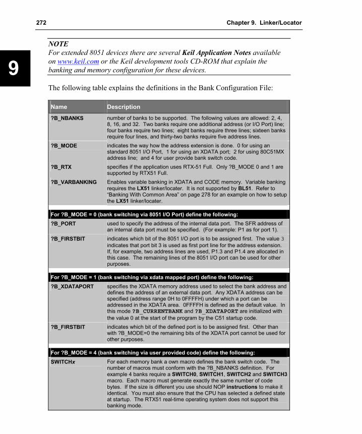
272 Chapter 9. Linker/Locator
9
NOTE For extended 8051 devices there are several Keil Application Notes available on www.keil.com or the Keil development tools CD-ROM that explain the banking and memory configuration for these devices.
The following table explains the definitions in the Bank Configuration File:
Name Description
?B_NBANKS number of banks to be supported. The following values are allowed: 2, 4, 8, 16, and 32. Two banks require one additional address (or I/O Port) line; four banks require two lines; eight banks require three lines; sixteen banks require four lines, and thirty-two banks require five address lines.
?B_MODE indicates the way how the address extension is done. 0 for using an standard 8051 I/O Port, 1 for using an XDATA port; 2 for using 80C51MX address line; and 4 for user provide bank switch code.
?B_RTX specifies if the application uses RTX-51 Full. Only ?B_MODE 0 and 1 are supported by RTX51 Full.
?B_VARBANKING Enables variable banking in XDATA and CODE memory. Variable banking requires the LX51 linker/locater. It is not supported by BL51. Refer to “Banking With Common Area” on page 278 for an example on how to setup the LX51 linker/locater.
For ?B_MODE = 0 (bank switching via 8051 I/O Port) define the following: ?B_PORT used to specify the address of the internal data port. The SFR address of
an internal data port must be specified. (For example: P1 as for port 1). ?B_FIRSTBIT indicates which bit of the 8051 I/O port is to be assigned first. The value 3
indicates that port bit 3 is used as first port line for the address extension. If, for example, two address lines are used, P1.3 and P1.4 are allocated in this case. The remaining lines of the 8051 I/O port can be used for other purposes.
For ?B_MODE = 1 (bank switching via xdata mapped port) define the following: ?B_XDATAPORT specifies the XDATA memory address used to select the bank address and
defines the address of an external data port. Any XDATA address can be specified (address range 0H to 0FFFFH) under which a port can be addressed in the XDATA area. 0FFFFH is defined as the default value. In this mode ?B_CURRENTBANK and ?B_XDATAPORT are initialized with the value 0 at the start of the program by the C51 startup code.
?B_FIRSTBIT indicates which bit of the defined port is to be assigned first. Other than with ?B_MODE=0 the remaining bits of the XDATA port cannot be used for other purposes.
For ?B_MODE = 4 (bank switching via user provided code) define the following: SWITCHx For each memory bank a own macro defines the bank switch code. The
number of macros must conform with the ?B_NBANKS definition. For example 4 banks require a SWITCH0, SWITCH1, SWITCH2 and SWITCH3 macro. Each macro must generate exactly the same number of code bytes. If the size is different you use should NOP instructions to make it identical. You must also ensure that the CPU has selected a defined state at startup. The RTX51 real-time operating system does not support this banking mode.

Macro Assembler and Utilities for 8051 and Variants 273
9
The Ax51 assembler is required to assemble L51_BANK.A51 or MX51BANK.A51. The source file should be copied as part of your project file. Public Symbols in L51_BANK.A51
Additional PUBLIC Symbols are provided in L51_BANK.A51 for your convenience. They are described below.
Name Description
?B_CURRENTBANK is a memory location in the DATA or SFR memory, which contains the currently selected memory bank. This memory location can be read for debugging. A modification of the memory location, however, does not cause a bank switching in most cases. Only required bits based on setting of ?B_NBANKS and ?B_FIRSTBIT are valid in this memory location. The bits, which are not required, must be masked out with a corresponding mask.
_SWITCHBANK is a Cx51 compatible function, which allows the bank address to be selected by the user program. This function can be used for bank switching if the constant memory is too small. Note that this C function can be called only from code in the common area. The function is accessed as follows: extern void switchbank (unsigned char bank_number); : : switchbank (0);
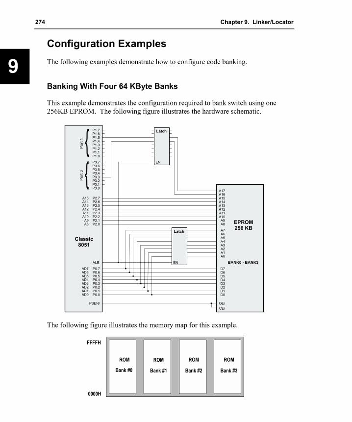
274 Chapter 9. Linker/Locator
9
Configuration Examples The following examples demonstrate how to configure code banking.
Banking With Four 64 KByte Banks
This example demonstrates the configuration required to bank switch using one 256KB EPROM. The following figure illustrates the hardware schematic.
P1.0P1.1P1.2P1.3
P1.5P1.4
P1.6P1.7
P3.0P3.1P3.2P3.3
P3.5P3.4
P3.6P3.7
P2.0P2.1P2.2P2.3
P2.5P2.4
P2.6P2.7
ALE
PSEN/
P0.0P0.1P0.2P0.3
P0.5P0.4
P0.6P0.7AD7
AD5AD6
AD4AD3AD2AD1AD0
A8A9
A10A11A12A13A14A15
Po
rt1 {
Po
rt3 {
Classic8051
EN
Latch
EN
Latch
A15A14
A16A17
A13A12A11A10A9A8
A1A2A3A4A5A6A7
A0
D1D2D3D4D5D6D7
D0
OE/
EPROM256 KB
BANK0 - BANK3
CE/
The following figure illustrates the memory map for this example.
ROM ROMROM ROM
Bank #0 Bank #1 Bank #2 Bank #3
0000H
FFFFH

Macro Assembler and Utilities for 8051 and Variants 275
9
One 256KB EPROM is used in this hardware configuration. The bank switching can be implemented by using two bank select address lines (in this example Port 1.5 and Port 3.3). L51_BANK.A51 can be configured as follows for this hardware configuration.
?N_BANKS EQU 4 ; Four banks are required.?B_MODE EQU 4 ; user-provided bank switch code is used.
The section that starts with IF ?B_MODE = 4 defines the code that switches between the code banks. This section needs to be configured as follows:
P1 DATA 90H ; I/O Port Addresses *P3 DATA 0B0H ; *; *SWITCH0 MACRO ; Switch to Memory Bank #0 *
CLR P3.3 ; Clear Port 3 Bit 3 *CLR P1.5 ; Clear Port 1 Bit 5 *ENDM *
; *SWITCH1 MACRO ; Switch to Memory Bank #1 *
SETB P3.3 ; Set Port 3 Bit 3 *CLR P1.5 ; Clear Port 1 Bit 5 *ENDM *
; *SWITCH2 MACRO ; Switch to Memory Bank #2 *
CLR P3.3 ; Clear Port 3 Bit 3 *SETB P1.5 ; Set Port 1 Bit 5 *ENDM *
; *SWITCH3 MACRO ; Switch to Memory Bank #3 *
SETB P3.3 ; Set Port 3 Bit 3 *SETB P1.5 ; Set Port 1 Bit 5 *ENDM *
You need to ensure that the CPU starts in a defined state at reset. Therefore the following code needs to be added to the STARTUP.A51 file of your application:
MOV SP,#?STACK-1; added for bank switchingP1 DATA 90H ; I/O Port AddressesP3 DATA 0B0H
EXTRN DATA (?B_CURRENTBANK)MOV ?B_CURRENTBANK,#0 ; select code bank 0CLR P3.3 ; Clear Port 3 Bit 3CLR P1.5 ; Clear Port 1 Bit 5
; endJMP ?C_START
The Lx51 linker/locator automatically places copies of the code and data in the common area into each bank so that the contents of all EPROM banks are identical in the address range of the common area. The BANKAREA control is not required since the default setting already defines address range 0 to 0xFFFF as banked area.
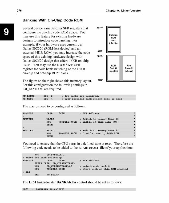
276 Chapter 9. Linker/Locator
9
Banking With On-Chip Code ROM
Several device variants offer SFR registers that configure the on-chip code ROM space. You may use this feature for existing hardware designs to introduce code banking. For example, if your hardware uses currently a Dallas 80C320 (ROM-less device) and an external 64KB ROM, you may increase the code space of this existing hardware design with Dallas 80C520 design that offers 16KB on-chip ROM. You may use the ROMSIZE SFR register for code bank switching of the 16KB on-chip and off-chip ROM block.
The figure on the right shows this memory layout. For this configuration the following settings in L51_BANK.A51 are required.
ROMBank #1(off-chip)
CommonROMArea
(off-chip)
4000h
FFFFh
3FFFh
0000h
ROMBank #0(on-chip)
?N_BANKS EQU 2 ; Two banks are required.?B_MODE EQU 4 ; user-provided bank switch code is used.
The macros need to be configured as follows:
ROMSIZE DATA 0C2H ; SFR Address *; *SWITCH0 MACRO ; Switch to Memory Bank #0 *
MOV ROMSIZE,#05H ; Enable on-chip 16KB ROM *ENDM *
; *SWITCH1 MACRO ; Switch to Memory Bank #1 *
MOV ROMSIZE,#00H ; Disable on-chip 16KB ROM *ENDM *
You need to ensure that the CPU starts in a defined state at reset. Therefore the following code needs to be added to the STARTUP.A51 file of your application:
MOV SP,#?STACK-1; added for bank switchingROMSIZE DATA 0C2H ; SFR Address
EXTRN DATA (?B_CURRENTBANK)MOV ?B_CURRENTBANK,#0 ; select code bank 0MOV ROMSIZE,#05H ; start with on-chip ROM enabled
; endJMP ?C_START
The Lx51 linker/locater BANKAREA control should be set as follows:
BL51 ... BANKAREA (0,0x3FFF)

Macro Assembler and Utilities for 8051 and Variants 277
9
Banking With XDATA Port
You may also use a latch or I/O device that is mapped into the XDATA space to extend the address lines of the 8051 device. The following application illustrates a hardware that uses a latch mapped into the XDATA space to address a 512KB EPROM.
P2.0P2.1P2.2P2.3
P2.5P2.4
P2.6P2.7
ALE
PSEN/
P0.0P0.1P0.2P0.3
P0.5P0.4
P0.6P0.7AD7
AD5AD6
AD4AD3AD2AD1AD0
A8A9
A10A11A12A13A14A15
Classic8051
EN
Latch
EN
Latch
A14A13A12A11A10A9A8
A1A2A3A4A5A6A7
A0
D1D2D3D4D5D6D7
D0
OE/
CE/
EPROM512 KB
Bank0-7
A17A16
A15
WR/
A18
The following figure illustrates the memory map for this example.
ROM ROMROM ROM
Bank #0 Bank #1 Bank #2 Bank #3
0000H
0FFFFH
ROM
Bank #4
ROM
Bank #5
ROM
Bank #6
ROM
Bank #7
For this hardware the L51_BANK.A51 file can be configured as follows:
?N_BANKS EQU 8 ; Eight banks are required.?B_MODE EQU 1 ; bank switch via xdata port.?B_XDATAPORT EQU 0 ; any I/O address can be given for the example.?B?FIRSTBIT EQU 0 ; bit 0 is used as first address line.
You need no additional configuration in the STARTUP.A51 file. The Lx51 linker/locator automatically places copies of the code and data in the common

278 Chapter 9. Linker/Locator
9
area into each bank so that the contents of all EPROM banks are identical in the address range of the common area. The BANKAREA control is not required since the default setting already defines address range 0 to 0xFFFF as banked area.
Banking With Common Area
The following schematic shows a hardware that offers a 32KB common area and seven 32KB code banks. A single EPROM is used to map the complete memory. Due to the address decoding logic, the code bank 0 is identical with the common area and should be therefore not used by your application. The design also provides 256KB xdata memory that is mapped the same way as the code memory. The xdata space might be used for variable banking.
P1.0P1.1P1.2P1.3
P1.5P1.4
P1.6P1.7
P3.0P3.1P3.2P3.3
P3.5P3.4
P3.6P3.7
P2.0P2.1P2.2P2.3
P2.5P2.4
P2.6P2.7
ALE
PSEN/
P0.0P0.1P0.2P0.3
P0.5P0.4
P0.6P0.7AD7
AD5AD6
AD4AD3AD2AD1AD0
A8A9
A10A11A12A13A14A15
Port
1 {
Port
3 {
Classic8051
A14A13A12A11A10A9A8
A1A2A3A4A5A6A7
A0
D1D2D3D4D5D6D7
D0
OE/
EPROM256 KB
Common(0x0000- 0x7FFF)
A15
Bank#1 - Bank#7(0x8000- 0x3FFFF)
A17
A16
EN
Latch
A1A2A3A4A5A6A7
A0
D1D2D3D4D5D6D7
D0
OE/
A14A13A12A11A10A9A8
A1A2A3A4A5A6A7
A0
D1D2D3D4D5D6D7
D0
WR/
RAM256 KB
Common(0x0000- 0x7FFF)
A15
Bank#1 - Bank#7(0x8000- 0x3FFFF)
A17
A16
A1A2A3A4A5A6A7
A0
D1D2D3D4D5D6D7
D0
RD/
A14A13A12A11A10A9A8
A1A2A3A4A5A6A7
A0
D1D2D3D4D5D6D7
D0
OE/
EPROM256 KB
Common(0x0000- 0x7FFF)
A15
Bank#1 - Bank#7(0x8000- 0x3FFFF)
A17
A16
A1A2A3A4A5A6A7
A0
D1D2D3D4D5D6D7
D0
OE/
RD/
WR/

Macro Assembler and Utilities for 8051 and Variants 279
9
The following figure illustrates the memory map for this example.
ROMROM ROM
Bank #1 Bank #2 Bank #3
8000H
0FFFFH
ROM
Bank #4
ROM
Bank #5
ROM
Bank #6
ROM
Bank #7
ROMCommon
Area
0000H
7FFFH ROM Bank #0 is not available it is physically thesame memory space as the cmmon area.
For this hardware the L51_BANK.A51 file can be configured as follows:
?N_BANKS EQU 8 ; Eight banks are required.?B_MODE EQU 0 ; banking via on-chip I/O Port.?B_VAR_BANKING EQU 1 ; you may use also variable banking.?B_PORT EQU 090H ; Port address of P1.?B_FIRSTBIT EQU 2 ; Bit 2 is used as the first address line.
You should not use the code bank 0 in your application, since this memory is effectively identical with the common area. Therefore no module of you application should be assigned to code bank 0. The Lx51 linker/locater BANKAREA control should be set as follows:
BL51 BANK1 {A.OBJ}, ..., BANK7{G.OBJ} ... BANKAREA (0x8000,0xFFFF)
If you are using variable banking, you need to use LX51 linker/locator. To define the additional memory the HDATA and HCONST memory classes are used. In this case the memory classes need to be set as follows:
LX51 BANK1 {A.OBJ}, ..., BANK7{G.OBJ} ... BANKAREA (0x8000,0xFFFF)CLASSES (XDATA (X:0-X:0x7FFF),
HDATA (X:0x18000-X:0x1FFFF,X:0x28000-X:0x2FFFF,X:0x38000-X:0x3FFFF,X:0x48000-X:0x4FFFF,X:0x58000-X:0x5FFFF,X:0x68000-X:0x6FFFF,X:0x78000-X:0x7FFFF),
HCONST (C:0x18000-C:0x1FFFF,C:0x28000-C:0x2FFFF,C:0x38000-C:0x3FFFF,C:0x48000-C:0x4FFFF,C:0x58000-C:0x5FFFF,C:0x68000-C:0x6FFFF,C:0x78000-C:0x7FFFF))
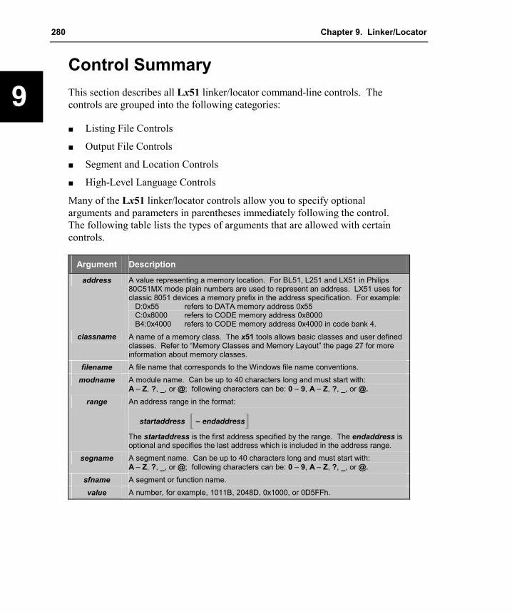
280 Chapter 9. Linker/Locator
9
Control Summary This section describes all Lx51 linker/locator command-line controls. The controls are grouped into the following categories:
�� Listing File Controls
�� Output File Controls
�� Segment and Location Controls
�� High-Level Language Controls
Many of the Lx51 linker/locator controls allow you to specify optional arguments and parameters in parentheses immediately following the control. The following table lists the types of arguments that are allowed with certain controls.
Argument Description
address A value representing a memory location. For BL51, L251 and LX51 in Philips 80C51MX mode plain numbers are used to represent an address. LX51 uses for classic 8051 devices a memory prefix in the address specification. For example: D:0x55 refers to DATA memory address 0x55 C:0x8000 refers to CODE memory address 0x8000 B4:0x4000 refers to CODE memory address 0x4000 in code bank 4.
classname A name of a memory class. The x51 tools allows basic classes and user defined classes. Refer to “Memory Classes and Memory Layout” the page 27 for more information about memory classes.
filename A file name that corresponds to the Windows file name conventions. modname A module name. Can be up to 40 characters long and must start with:
A – Z, ?, _, or @; following characters can be: 0 – 9, A – Z, ?, _, or @. range An address range in the format:
startaddress � – endaddress�
The startaddress is the first address specified by the range. The endaddress is optional and specifies the last address which is included in the address range.
segname A segment name. Can be up to 40 characters long and must start with: A – Z, ?, _, or @; following characters can be: 0 – 9, A – Z, ?, _, or @.
sfname A segment or function name. value A number, for example, 1011B, 2048D, 0x1000, or 0D5FFh.

Macro Assembler and Utilities for 8051 and Variants 281
9
Listing File Controls The Lx51 linker/locator generates a listing file that contains information about the link/locate process. This file is sometimes referred to as a map file. The following controls specify the filename, format, and information that is included in the listing file. For a detailed description of each control refer to the page listed in the table.
BL51 LX51, L251 Page Description
DISABLEWARNING DISABLEWARNING 282 Disables specified warning messages.
IXREF IXREF 283 Includes a cross reference report.
– NOCOMMENTS 284 Excludes comment information.
NOLINES NOLINES 285 Excludes line number information.
NOMAP NOMAP 286 Excludes memory map information.
NOPRINT NOPRINT 290 Disables generation of a listing file.
NOPUBLICS NOPUBLICS 287 Excludes public symbol information.
NOSYMBOLS NOSYMBOLS 288 Excludes local symbol information.
PAGELENGTH(n) PAGELENGTH(n) 289 Sets number of lines in each page.
PAGEWIDTH(n) PAGEWIDTH(n) 289 Sets number of characters in each line.
PRINT PRINT 290 Specifies the name of the listing file.
– PRINTCONTROLS 291 Excludes specific debugging information.
– PURGE 292 Excludes all debugging information.
– WARNINGLEVEL(n) 293 Controls the types and severity of warnings generated.

282 Chapter 9. Linker/Locator
9
DISABLEWARNING
Abbreviation: DW
Arguments: DISABLEWARNING (number, �…�)
Default: All warning messages are displayed.
µVision2 Control: Options – Lx51 Misc – Warnings – Disable Warning Numbers.
Description: The DISABLEWARNING control lets you to selectively disable Linker warnings. The warning numbers that should be suppressed are specified in parenthesis. The following examples disables the report of Warning Number 1 and 5.
Example: LX51 myfile.obj DISABLEWARNING (1, 5)

Macro Assembler and Utilities for 8051 and Variants 283
9
IXREF
Abbreviation: IX
Arguments: IXREF �(NOGENERATED, NOLIBRARIES)�
Default: No cross reference is generated in the listing file.
µVision2 Control: Options – Listing – Linker Listing – Cross Reference
Description: The IXREF control instructs the Lx51 linker/locator to include a cross reference report in the listing file. The cross reference is an alphabetically sorted list of all PUBLIC and EXTERN symbols in your program along with memory type and module names. The first module name is the module in which the PUBLIC symbol is defined. Further module names show the modules in which the EXTERN symbol is defined. If no PUBLIC symbol is present, ** UNRESOLVED ** is shown as first module name. The option NOGENERATED suppresses symbols starting with ‘?’. These question mark symbols are normally produced by the compiler for calling specific C functions or passing parameters. The option NOLIBRARIES suppresses those symbols, which are defined in a library file.
Example: BL51 myfile.obj IXREF
LX51 myfile.obj IXREF (NOGENERATED)
L251 myfile.obj IXREF(NOLIBRARIES, NOGENERATED)

284 Chapter 9. Linker/Locator
9
NOCOMMENTS
Restriction: This control is available in LX51 and L251 only.
Abbreviation: NOCO
Arguments: None
Default: include comment information.
Description: The NOCOMMENTS control removes the comment records contained in the input files from the listing file and the object output file. Comment records are added to the object module to identify the compiler or assembler that produced the object file. If you want to exclude comment information just from the listing file you have to use the PRINTCONTROL control.
See Also: OBJECTCONTROLS, PRINTCONTROLS
Example: L251 MYPROG.OBJ NOCOMMENTS

Macro Assembler and Utilities for 8051 and Variants 285
9
NOLINES
Abbreviation: NOLI
Arguments: None
Default: Include line number information
µVision2 Control: Options – Listing – Linker Listing – Line Numbers
Description: For the BL51 linker/locator, the NOLINES control excludes line number information in the listing file. For the LX51 linker/locater and the L251 linker/locator, the NOLINES control excludes line number information in the listing file and object output file. If you want to exclude line number information just from the listing file you have to use the PRINTCONTROL control.
NOTE Line numbers are address information about the source code lines and are used for debugging purposes. The Lx51 linker/locator generates line numbers for source modules in your program only, if the Ax51 assembler and Cx51 compiler include that information in the input object files. Refer to the assembler control NOLINES on page 199 and to the Cx51 User’s Guide for information on including line number information in the object files.
See Also: NODEBUGLINES, PRINTCONTROLS, OBJECTCONTROLS
Example: BL51 MYPROG.OBJ NOLINES
286 Chapter 9. Linker/Locator
9
NOMAP
Abbreviation: NOMA
Arguments: None
Default: Include a memory map in the listing file.
µVision2 Control: Options – Listing – Linker Listing – Memory Map
Description: The NOMAP control prevents the Lx51 linker/locator from including the memory map in the listing file.
Example: BL51 MYPROG.OBJ NOMAP

Macro Assembler and Utilities for 8051 and Variants 287
9
NOPUBLICS
Abbreviation: NOPU
Arguments: None
Default: Include information about public symbols
µVision2 Control: Options – Listing – Linker Listing – Public Symbols
Description: For the BL51 linker/locator, the NOPUBLICS control excludes public symbols from the listing file. For the LX51 linker/locater and the L251 linker/locator, the NOLINES control excludes public symbols from the listing file and object output file. If you want to exclude public symbols just from the listing file you have to use the PRINTCONTROLS control.
See Also: NODEBUGPUBLICS, PRINTCONTROLS, OBJECTCONTROLS
Example: BL51 MYPROG.OBJ NOPUBLICS
288 Chapter 9. Linker/Locator
9
NOSYMBOLS
Abbreviation: NOSY
Arguments: None
Default: Include information about local program symbols
µVision2 Control: Options – Listing – Linker Listing – Local Symbols
Description: For the BL51 linker/locator, the NOSYMBOLS control excludes local symbols from the listing file. For the LX51 linker/locater and the L251 linker/locator, the NOSYMBOLS control excludes local symbols from the listing file and object output file. If you want to exclude local symbols just from the listing file you have to use the PRINTCONTROLS control.
NOTE Symbols information is typically used for debugging purposes. The Lx51 linker/locator generates symbol information for source modules in your program only, if the Ax51 assembler and Cx51 compiler include that information in the input object files. Refer to the assembler control DEBUG on page 187 and to the Cx51 User’s Guide for information on including symbol information in the object files.
See Also: NODEBUGSYMBOLS, PRINTCONTROLS, OBJECTCONTROLS
Example: BL51 MYPROG.OBJ NOSYMBOLS

Macro Assembler and Utilities for 8051 and Variants 289
9
PAGELENGTH / PAGEWIDTH
Abbreviation: PL
Arguments: PAGELENGTH (value) PAGEWIDTH (value)
Default: PAGELENGTH (60) PAGEWIDTH (132)
µVision2 Control: Options – Listing – Page Width, Page Lenght
Description: The PAGELENGTH control sets the maximum number of lines per page for the listing file. The PAGEWIDTH control defines the maximum width of lines in the listing file. The page width may be set to a number in the 72 to 132 range.
Examples: BL51 PROG.OBJ TO PROG.ABS PAGELENGTH(50) PAGEWIDTH(100)
L251 MYPROG.OBJ PAGELENGTH(30000) PAGEWIDTH(120)
290 Chapter 9. Linker/Locator
9
PRINT / NOPRINT
Abbreviation: PR / NOPR
Arguments: PRINT (filename)
Default: The listing file is generated using the basename of the output file. BL51 use the extension .M51; LX51 and L251 use the extension .MAP as default for the listing file.
µVision2 Control: Options – Listing – Select Folder for Listing Files
Description: The PRINT control allows you to specify the name of the listing file that is generated by the Lx51 linker/locator. The name must be enclosed in parentheses immediately following the PRINT control on the command line. The NOPRINT control prevents the linker/locater from generating a listing file.
Example: LX51 MYPROG.OBJ TO MYPROG.ABS PRINT(OUTPUT.MAP)
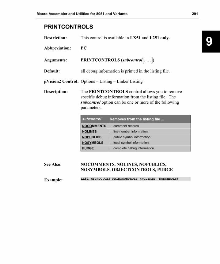
Macro Assembler and Utilities for 8051 and Variants 291
9
PRINTCONTROLS
Restriction: This control is available in LX51 and L251 only.
Abbreviation: PC
Arguments: PRINTCONTROLS (subcontrol�, …�)
Default: all debug information is printed in the listing file.
µVision2 Control: Options – Listing – Linker Listing
Description: The PRINTCONTROLS control allows you to remove specific debug information from the listing file. The subcontrol option can be one or more of the following parameters:
subcontrol Removes from the listing file ...
NOCOMMENTS ... comment records.
NOLINES ... line number information.
NOPUBLICS ... public symbol information.
NOSYMBOLS ... local symbol information.
PURGE ... complete debug information.
See Also: NOCOMMENTS, NOLINES, NOPUBLICS, NOSYMBOLS, OBJECTCONTROLS, PURGE
Example: LX51 MYPROG.OBJ PRINTCONTROLS (NOLINES, NOSYMBOLS)

292 Chapter 9. Linker/Locator
9
PURGE
Restriction: This control is available in LX51 and L251 only.
Abbreviation: PU
Default: all debug information is processed.
µVision2 Control: Options – Lx51 Misc – Misc Controls – enter the control.
Description: The PURGE control allows you to remove the complete debug information contained in the input files from the listing file and the object output file. PURGE has the same effect as specifying NOCOMMENTS, NOLINES, NOPUBLICS and NOSYMBOLS. The debug information is only required for program debugging and has no influence on the executeable code. If you want to exclude line number information just from the listing file you have to use the PRINTCONTROLS control.
See Also: NOCOMMENTS, NOLINES, NOPUBLICS, NOSYMBOLS, OBJECTCONTROLS, PRINTCONTROLS
Example: L251 MYPROG.OBJ PURGE

Macro Assembler and Utilities for 8051 and Variants 293
9
WARNINGLEVEL
Restriction: This control is available in LX51 and L251 only.
Abbreviation: WL
Arguments: A number between 0 .. 2.
Default: WARNINGLEVEL (2)
µVision2 Control: Options – Lx51 Misc – Warnings – Warning Level.
Description: The WARNINGLEVEL control allows you to suppress linker warnings. Refer to “Warnings” on page 335 for a full list of the linker warnings.
Warning Level Description
0 Disables almost all linker warnings.
1 Lists only those warnings that may generate incorrect code, including information about data type mismatches of total different types.
2 (Default) Lists all WARNING messages including warnings all data type mismatches.
Example: LX51 MYFILE.OBJ WL (1)

294 Chapter 9. Linker/Locator
9
Example Listing File
The following example includes all optional sections of the listing file.
L251 LINKER/LOCATER V3.00 09/06/2000 12:09:21 PAGE 1
L251 LINKER/LOCATER V3.00, INVOKED BY: The listing file shows the commandE:\L251.EXE MEASURE.OBJ, MCOMMAND.OBJ, GETLINE.OBJ IXREF line that invoked the linker.
CPU MODE: 251 SOURCE MODE CPU mode, interrupt frame size,INTR FRAME: 4 BYTES SAVED ON INTERRUPT memory model and floating point MEMORY MODEL: SMALL WITH FLOATING POINT ARITHMETIC arithmetic are listed.
INPUT MODULES INCLUDED: Object modules that were includedMEASURE.OBJ (MEASURE) along with translator information
COMMENT TYPE 0: C251 V3.00 are listed.MCOMMAND.OBJ (MCOMMAND)
COMMENT TYPE 0: C251 V3.00GETLINE.OBJ (GETLINE)
COMMENT TYPE 0: C251 V3.00C:\KEIL\C251\LIB\C2SFPS.LIB (?C_FPADD)
COMMENT TYPE 0: A251 V3.00::
ACTIVE MEMORY CLASSES OF MODULE: MEASURE (MEASURE) LX51 and L251 list an overview of all memory classes in used. BASE START END MEMORY CLASS==========================================FF0000H FF0000H FFFFFFH CODE000000H 000000H 00007FH DATA000000H 000000H 0000FFH IDATA010000H 010000H 01FFFFH XDATA000020H.0 000020H.0 00002FH.7 BIT000000H 000000H 00FFFFH EDATA
The memory map is included MEMORY MAP OF MODULE: MEASURE (MEASURE) You can disable the memory map using the NOMAP control. START STOP LENGTH ALIGN RELOC MEMORY CLASS SEGMENT NAME=========================================================================000000H 000007H 000008H --- AT.. DATA "REG BANK 0"000008H 00000FH 000008H --- AT.. DATA "REG BANK 1"000010H 000010H 000001H BYTE UNIT DATA ?DT?GETCHAR000011H 00001FH 00000FH BYTE UNIT IDATA _IDATA_GROUP_000020H.0 000020H.2 000000H.3 BIT UNIT BIT ?BI?MEASURE000020H.3 000020H.3 000000H.1 BIT UNIT BIT ?BI?GETCHAR000020H.4 000021H.6 000001H.3 BIT UNIT BIT _BIT_GROUP_000022H 000039H 000018H BYTE UNIT DATA ?DT?MEASURE00003AH 000065H 00002CH BYTE UNIT DATA _DATA_GROUP_000066H 000165H 000100H BYTE UNIT EDATA ?STACK010000H 011FF7H 001FF8H BYTE UNIT XDATA ?XD?MEASUREFF0000H FF0002H 000003H --- OFFS.. CODE ?CO?START251?3FF0003H FF0008H 000006H BYTE UNIT CODE ?PR?GETCHAR?UNGETCHAR
:: An overlay map is listed after the
OVERLAY MAP OF MODULE: MEASURE (MEASURE) memory map. The overlay map shows the call tree of your application. FUNCTION/MODULE BIT_GROUP DATA_GROUP IDATA_GROUP--> CALLED FUNCTION/MODULE START STOP START STOP START STOP============================================================================TIMER0/MEASURE ----- ----- ----- ----- ----- -------> SAVE_CURRENT_MEASUREMENTS/MEASURE
*** NEW ROOT *************************
?C_C251STARTUP ----- ----- ----- ----- ----- -----
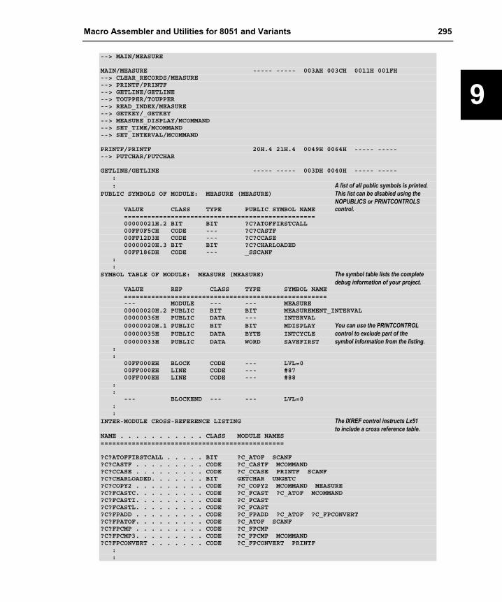
Macro Assembler and Utilities for 8051 and Variants 295
9
--> MAIN/MEASURE
MAIN/MEASURE ----- ----- 003AH 003CH 0011H 001FH--> CLEAR_RECORDS/MEASURE--> PRINTF/PRINTF--> GETLINE/GETLINE--> TOUPPER/TOUPPER--> READ_INDEX/MEASURE--> GETKEY/_GETKEY--> MEASURE_DISPLAY/MCOMMAND--> SET_TIME/MCOMMAND--> SET_INTERVAL/MCOMMAND
PRINTF/PRINTF 20H.4 21H.4 0049H 0064H ----- -------> PUTCHAR/PUTCHAR
GETLINE/GETLINE ----- ----- 003DH 0040H ----- -----:: A list of all public symbols is printed.
PUBLIC SYMBOLS OF MODULE: MEASURE (MEASURE) This list can be disabled using the NOPUBLICS or PRINTCONTROLS
VALUE CLASS TYPE PUBLIC SYMBOL NAME control.=================================================00000021H.2 BIT BIT ?C?ATOFFIRSTCALL00FF0F5CH CODE --- ?C?CASTF00FF12D3H CODE --- ?C?CCASE00000020H.3 BIT BIT ?C?CHARLOADED00FF186DH CODE --- _SSCANF
::
SYMBOL TABLE OF MODULE: MEASURE (MEASURE) The symbol table lists the complete debug information of your project.
VALUE REP CLASS TYPE SYMBOL NAME====================================================--- MODULE --- --- MEASURE00000020H.2 PUBLIC BIT BIT MEASUREMENT_INTERVAL00000036H PUBLIC DATA --- INTERVAL00000020H.1 PUBLIC BIT BIT MDISPLAY You can use the PRINTCONTROL00000035H PUBLIC DATA BYTE INTCYCLE control to exclude part of the 00000033H PUBLIC DATA WORD SAVEFIRST symbol information from the listing.
::
00FF000EH BLOCK CODE --- LVL=000FF000EH LINE CODE --- #8700FF000EH LINE CODE --- #88
::
--- BLOCKEND --- --- LVL=0::
INTER-MODULE CROSS-REFERENCE LISTING The IXREF control instructs Lx51 to include a cross reference table. NAME . . . . . . . . . . . CLASS MODULE NAMES===============================================
?C?ATOFFIRSTCALL . . . . . BIT ?C_ATOF SCANF?C?CASTF . . . . . . . . . CODE ?C_CASTF MCOMMAND?C?CCASE . . . . . . . . . CODE ?C_CCASE PRINTF SCANF?C?CHARLOADED. . . . . . . BIT GETCHAR UNGETC?C?COPY2 . . . . . . . . . CODE ?C_COPY2 MCOMMAND MEASURE?C?FCASTC. . . . . . . . . CODE ?C_FCAST ?C_ATOF MCOMMAND?C?FCASTI. . . . . . . . . CODE ?C_FCAST?C?FCASTL. . . . . . . . . CODE ?C_FCAST?C?FPADD . . . . . . . . . CODE ?C_FPADD ?C_ATOF ?C_FPCONVERT?C?FPATOF. . . . . . . . . CODE ?C_ATOF SCANF?C?FPCMP . . . . . . . . . CODE ?C_FPCMP?C?FPCMP3. . . . . . . . . CODE ?C_FPCMP MCOMMAND?C?FPCONVERT . . . . . . . CODE ?C_FPCONVERT PRINTF
::
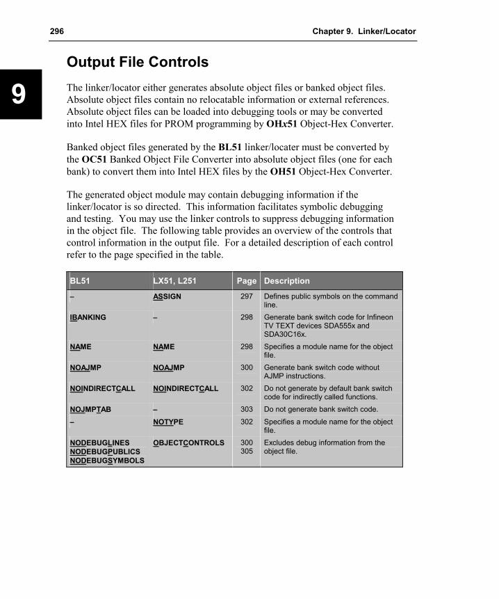
296 Chapter 9. Linker/Locator
9
Output File Controls The linker/locator either generates absolute object files or banked object files. Absolute object files contain no relocatable information or external references. Absolute object files can be loaded into debugging tools or may be converted into Intel HEX files for PROM programming by OHx51 Object-Hex Converter.
Banked object files generated by the BL51 linker/locater must be converted by the OC51 Banked Object File Converter into absolute object files (one for each bank) to convert them into Intel HEX files by the OH51 Object-Hex Converter.
The generated object module may contain debugging information if the linker/locator is so directed. This information facilitates symbolic debugging and testing. You may use the linker controls to suppress debugging information in the object file. The following table provides an overview of the controls that control information in the output file. For a detailed description of each control refer to the page specified in the table.
BL51 LX51, L251 Page Description
– ASSIGN 297 Defines public symbols on the command line.
IBANKING – 298 Generate bank switch code for Infineon TV TEXT devices SDA555x and SDA30C16x.
NAME NAME 298 Specifies a module name for the object file.
NOAJMP NOAJMP 300 Generate bank switch code without AJMP instructions.
NOINDIRECTCALL NOINDIRECTCALL 302 Do not generate by default bank switch code for indirectly called functions.
NOJMPTAB – 303 Do not generate bank switch code.
– NOTYPE 302 Specifies a module name for the object file.
NODEBUGLINES NODEBUGPUBLICS NODEBUGSYMBOLS
OBJECTCONTROLS 300305
Excludes debug information from the object file.

Macro Assembler and Utilities for 8051 and Variants 297
9
ASSIGN
Restriction: This control is available in LX51 and L251 only.
Abbreviation: AS
Arguments: ASSIGN (symname (value) �, ...�)
Default: None
µVision2 Control: Options – Lx51 Misc – Assign.
Description: ASSIGN defines a PUBLIC symbol whit a numeric value at Lx51 linker/locater level. The PUBLIC symbol is handled as a number without a specific memory class and matches with an unresolved external symbol with the same name.
Example: L251 MYFILE.OBJ ASSIGN (FUNC (0x2000), BITVAR (20H.2))
In this example the public symbols FUNC and BITVAR are defined. The value 0x2000 is given as value for FUNC. The value 20H.2 is used as bit-address for BITVAR.
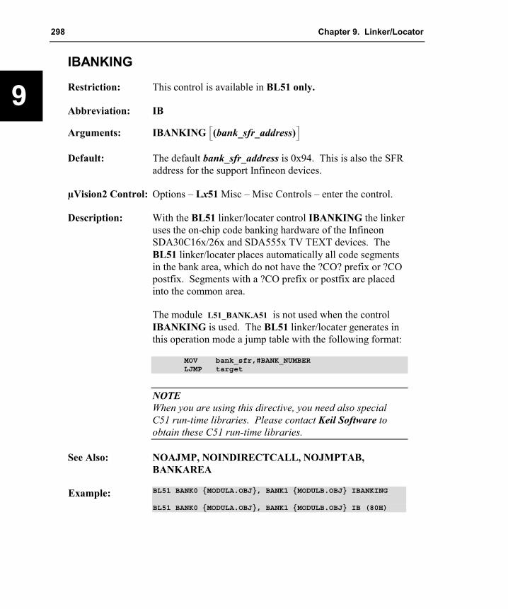
298 Chapter 9. Linker/Locator
9
IBANKING
Restriction: This control is available in BL51 only.
Abbreviation: IB
Arguments: IBANKING �(bank_sfr_address)�
Default: The default bank_sfr_address is 0x94. This is also the SFR address for the support Infineon devices.
µVision2 Control: Options – Lx51 Misc – Misc Controls – enter the control.
Description: With the BL51 linker/locater control IBANKING the linker uses the on-chip code banking hardware of the Infineon SDA30C16x/26x and SDA555x TV TEXT devices. The BL51 linker/locater places automatically all code segments in the bank area, which do not have the ?CO? prefix or ?CO postfix. Segments with a ?CO prefix or postfix are placed into the common area.
The module L51_BANK.A51 is not used when the control IBANKING is used. The BL51 linker/locater generates in this operation mode a jump table with the following format:
MOV bank_sfr,#BANK_NUMBERLJMP target
NOTE When you are using this directive, you need also special C51 run-time libraries. Please contact Keil Software to obtain these C51 run-time libraries.
See Also: NOAJMP, NOINDIRECTCALL, NOJMPTAB, BANKAREA
Example: BL51 BANK0 {MODULA.OBJ}, BANK1 {MODULB.OBJ} IBANKING
BL51 BANK0 {MODULA.OBJ}, BANK1 {MODULB.OBJ} IB (80H)

Macro Assembler and Utilities for 8051 and Variants 299
9
NAME
Abbreviation: NA
Arguments: NAME (modulename)
Default: Module name of the first object file in the input list is used.
µVision2 Control: Options – Lx51 Misc – Misc Controls – enter the control.
Description: Use the NAME control to specify a module name for the absolute object module that the BL51 linker/locator generates. The NAME control may be accompanied by the module name (in parentheses) that you want to assign. If no module name is specified with the NAME control, the name of the first input module is used for the module name.
NOTE The module name specified with the NAME control is not the filename of the absolute object file. The module name is stored in the object module file and may be accessed only by a program that reads the contents of that file.
Example: BL51 MYPROG.OBJ TO MYPROG.ABS NAME(BIGPROG)
In this example BIGPROG is the module name stored in the object file.

300 Chapter 9. Linker/Locator
9
NOAJMP
Abbreviation: NOAJ
Default: The Lx51 linker/locater generates for code banking applications an inter-bank jump table. This bank switch table is used for jumps into a code bank from a different code bank or the common area. Depending on the table size, the linker uses AJMP or LJMP instructions within this bank switch table.
µVision2 Control: Options – Lx51 Misc – Misc Controls – enter the control.
Description: With the NOAJMP control you can disable the AJMP instruction in the inter-bank jump table. This option is required for 8051 derivatives that are not supporting the AJMP instruction.
See Also: IBANKING, NOINDIRECTCALL, NOJMPTAB, BANKAREA
Example: BL51 MYPROG.OBJ NOAJMP

Macro Assembler and Utilities for 8051 and Variants 301
9
NODEBUGLINES, NODEBUGPUBLICS, NODEBUGSYMBOLS
Restriction: This control is available in BL51 only. For LX51 and L251 use the OBJECTCONTROLS control.
Abbreviation: NODL, NODP, NODS
Default: Include complete debug information in the output file.
µVision2 Control: Options – Lx51 Misc – Misc Controls – enter the control.
Description: The NODEBUGLINES control directs the BL51 linker/locator to exclude line number information from the output object file. The NODEBUGPUBLICS control excludes public symbol information from the output object file. The NODEBUGSYMBOLS control excludes local symbol information from the output object file.
NOTE Line number and symbol information in the absolute object file is used for symbolic debugging in the µVision2 debugger or in-circuit emulator. If you exclude debug information, source level debugging of your program is no longer possible.
See Also: NOLINES, NOPUBLICS, NOSYMBOLS, OBJECTCONTROLS, PRINTCONTROLS
Example: BL51 MYPROG.OBJ NODEBUGLINES NODEBUGSYMBOLS
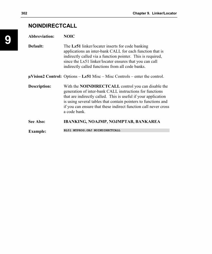
302 Chapter 9. Linker/Locator
9
NOINDIRECTCALL
Abbreviation: NOIC
Default: The Lx51 linker/locater inserts for code banking applications an inter-bank CALL for each function that is indirectly called via a function pointer. This is required, since the Lx51 linker/locater ensures that you can call indirectly called functions from all code banks.
µVision2 Control: Options – Lx51 Misc – Misc Controls – enter the control.
Description: With the NOINDIRECTCALL control you can disable the generation of inter-bank CALL instructions for functions that are indirectly called. This is useful if your application is using several tables that contain pointers to functions and if you can ensure that these indirect function call never cross a code bank.
See Also: IBANKING, NOAJMP, NOJMPTAB, BANKAREA
Example: BL51 MYPROG.OBJ NOINDIRECTCALL

Macro Assembler and Utilities for 8051 and Variants 303
9
NOJMPTAB
Restriction: This control is available in BL51 only.
Abbreviation: NOJT
Default: The Lx51 linker/locater generates for code banking automatically an inter-bank jump table or bank switch table. For each function that is located in a code bank and is called from a different code bank or the common area the linker inserts a bank switch code into the inter-bank jump table redirects the function call to this table.
µVision2 Control: Options – Lx51 Misc – Misc Controls – enter the control.
Description: When the NOJMPTAB control is stated, BL51 no longer inserts inter-bank calls for program calls. This feature is implemented to use the user-defined bank switch mechanism for code banking. The NOJMPTAB directive modifies the following features of BL51:
�� The linker no longer needs the bank switch configuration file: L51_BANK.OBJ.
�� The linker does not modify any jump call instructions.
The linker does not generate any warnings if a jump/call is made to another bank. The user must ensure that the proper bank is selected before a call is made since the BL51 linker/locator no longer selects the bank automatically.
See Also: IBANKING, NOAJMP, NOINDIRECTCALL, BANKAREA
Example: BL51 MYPROG.OBJ NOJMPTAB

304 Chapter 9. Linker/Locator
9
NOTYPE
Restriction: This control is available in LX51 and L251 only.
Syntax: NOTYPE
Abbreviation: NOTY
Default: Include complete type information in the output file.
µVision2 Control: Options – Lx51 Misc – Misc Controls – enter the control.
Description: The NOTYPE control removes symbol type information for debug symbols from the output file. The symbol type information is only required for program debugging and has no influence on the executable code.
NOTE Symbol type information in the absolute object file is used for symbolic debugging in the µVision2 debugger or in-circuit emulator. The Cx51 compiler generates complete symbol information up to structure members and parameter passing values. If you exclude symbol type information, you might no be able to display variables during debugging.
See also: OBJECTCONTROL, PURGE
Example: LX51 file1.obj NOTYPE

Macro Assembler and Utilities for 8051 and Variants 305
9
OBJECTCONTROLS
Restriction: This control is available in LX51 and L251 only.
Abbreviation: OC
Arguments: OBJECTCONTROLS (subcontrol�, …�)
Default: Include complete debug information in the output file.
µVision2 Control: Options – Lx51 Misc – Misc Controls – enter the control.
Description: The OBJECTCONTROLS control allows you to remove specific debug information from the object output file. The subcontrol option can be one or more of the following parameters:
subcontrol Removes from the object output file ...
NOCOMMENTS ... comment records.
NOLINES ... line number information.
NOPUBLICS ... public symbol information.
NOSYMBOLS ... local symbol information.
PURGE ... complete debug information.
See Also: NOCOMMENTS, NOLINES, NOPUBLICS, NOSYMBOLS, OBJECTCONTROLS, PURGE
Example: LX51 MYPROG.OBJ OBJECTCONTROLS (NOCOMMENTS)

306 Chapter 9. Linker/Locator
9
Segment and Memory Location Controls The Lx51 linker/locator allows you to specify the size of the different memory areas or memory classes, the order of the segments within the different memory areas, and the location or absolute memory address of different segments. Also the size of segments can be manipulated and specific memory areas can be excluded from being used. These segment manipulations are performed using the following controls.
BL51 LX51, L251 Page Description
BANKAREA BANKAREA 307 Specifies the address range where the code banks are located.
BANKx – 308 Locates and orders segments in code bank x (where x is a code bank from 0 to 31).
BIT – 309 Locates and orders BIT segments. – CLASSES 311 Specifies a physical address range for
segments in a memory class. CODE – 313 Locates and orders CODE segments. DATA – 314 Locates and orders DATA segments. IDATA – 315 Locates and orders IDATA segments. NOSORTSIZE NOSORTSIZE 316 Disable size sorting for segments before
allocating the memory. PDATA – 316 Specifies start address for PDATA
segments. PRECEDE – 318 Locates and orders segments that should
precede others in DATA memory. RAMSIZE – 319 Specifies size of DATA and IDATA memory. – RESERVE 320 Reserves memory ranges and prevents the
linker from using these memory areas. – SEGMENTS 321 Defines physical memory addresses and
orders for specified segments. – SEGSIZE 323 Modifies the size for a specific segment.
STACK – 324 Locates and orders STACK segments. XDATA – 325 Locates and orders XDATA segments.
The Lx51 linker/locator locates segments in according their memory class and follows a predefined order of precedence. The standard allocation algorithm usually produces the best workable solution and does not requiring you to enter any segment names on the command line. The controls described in this section allow you to define the physical memory layout of your target system and more closely control the location of segments within the different memory classes. Refer to “Locating Programs to Physical Memory” on page 253 for examples on how to define the available memory in your x51 system.

Macro Assembler and Utilities for 8051 and Variants 307
9
BANKAREA
Abbreviation: BA
Arguments: BANKAREA (start_address, end_address)
Default: None
µVision2 Control: Options – Target – Code Banking – Bank Area.
Description: Use the BANKAREA control to specify the starting and ending address of the area where the code banks will be located. The addresses specified should reflect the actual address where the code bank ROMs are physically mapped. All segments that are assigned to a bank will be located within this address range unless they are defined differently using the BANKx control. Refer to “Bank Switching” on page 268 for more information about the code banking controls.
See Also: BANKx
Example: LX51 COMMON{C_ROOT.OBJ}, BANK0{C_BANK0.OBJ},BANK0{C_BANK0.OBJ}, BANK1{C_BANK1.OBJ},BANK2{C_BANK2.OBJ} TO MYPROG.ABS &BANKAREA(8000H,0FFFFH)

308 Chapter 9. Linker/Locator
9
BANKx
Restriction: This control is available in BL51 only. For LX51 and L251 use the SEGMENTS control.
Abbreviation: B0, B1, B2, … B30, B31
Arguments: BANKx (�start_address� �segname �(address)� �, …��)
µVision2 Control: Options – BL51 Misc – Misc Controls – enter the control.
Description: Use the BANKx control to specify a code bank for segments (x in BANKx is replaced by a bank number). Refer to “Bank Switching” on page 268 for more information about the code banking controls.
Segments are located in the specified code bank starting at start_address or address 0000h if start_address is not specified. If an address is specified the segment referred by segname will be located at this address.
If you allocate a constant segment of a Cx51 program into a code bank, you must manually ensure that the proper code bank is used when accessing that constant data. You can do this with the switchbank function that is defined in the L51_BANK.A51 module. “BANK_EX2 – Banking with Constants” on page 377 shows a complete example program.
See Also: BANKAREA, CODE
Example: This example will locate the segment ?PR?FUNC1?A that belongs to the C function func1 in module “A.C” into code bank 1 starting at address 0x8000. The segment ?PR?FUNC1?A will be located at address 0x8200.
BL51 COMMON{A.OBJ}, BANK0{B.OBJ}BANK1(0x8000, ?PR?FUNC1?A, ?PR?FUNC2?B(0x8200))

Macro Assembler and Utilities for 8051 and Variants 309
9
BIT
Restriction: This control is available in BL51 only. For LX51 and L251 use the CLASSES and SEGMENTS control.
Abbreviation: BI
Arguments: BIT (�start_address� �segname �(address)� �, …��)
µVision2 Control: Options – BL51 Locate – Bit.
Description: The BIT control allows you to specify:
�� The starting address for segments placed in the bit-addressable internal data space
�� The order of segments within the bit-addressable internal data space
�� The absolute memory location of segments in the bit-addressable internal data space.
Addresses that you specify with the BIT control are bit addresses. Bit addresses 00h through 7Fh reference bits in DATA memory bytes from byte address 20h to 2Fh (16 bytes of 8 bits each, 16 × 8 = 128 = 80h). Bit addresses that are evenly divisible by 8 are aligned on a byte boundary. A DATA segment that is bit-addressable can be located with the BIT control; however, the bit address specified must be byte aligned, that means evenly divisible by 8.
See Also: CODE, DATA, IDATA, XDATA
Examples: The following example specifies that relocatable BIT segments be located at or after bit address 48 decimal (30 hex) which is equivalent to byte address 26H.0 in the data memory:
BL51 MYPROG.OBJ BIT(48)
or BL51 MYPROG.OBJ BIT(0x30)

310 Chapter 9. Linker/Locator
9
To specify the order for segments, you must include the segment names, separated by commas. The following example places the ?DT?A, ?DT?B, and ?DT?C segments at the beginning of the bit-addressable DATA memory.
BL51 MYPROG.OBJ,A.OBJ,B.OBJ,C.OBJ BIT(?DT?A,?DT?B,?DT?C)
You may also specify the bit address for the segments. The following example places the ?DT?A and ?DT?B segments at 28h and 30h:
BL51 MYPROG.OBJ,A.OBJ,B.OBJ BIT(?DT?A(28h),?DT?B(30h))

Macro Assembler and Utilities for 8051 and Variants 311
9
CLASSES
Restriction: This control is available in LX51 and L251 only.
Abbreviation: CL
Arguments: CLASSES (classname (range�, …�) �, …� )
Default: None
µVision2 Control: Options – Lx51 Locate – User Classes.
Description: The CLASSES control specifies the physical address range for segments within a memory class. The CLASSES control provides an efficient way to define the physical memory layout. If the address limits for a memory class are not specified with the CLASSES control, the Lx51 linker/locater uses the physical address limits of the memory class. The address ranges that are used are listed in the linker MAP file in the section ACTIVE MEMORY CLASSES. It is recommended to check this section of the MAP file, since it lists where the Lx51 linker/locater assumes memory in your target hardware. More information about “Locating Programs to Physical Memory” can be found on page 253.
With the CLASSES control the absolute address for segments with the relocation type OFFS can be modified. For more information on how to declare such segments refer to “Relocation Type” on page 103. The offset is specified as first address in the range field with a ‘$’ prefix, for example: CLASSES (CODE ($0xFF8000, 0xFF8000 - 0xFFFFFF). In this case all segments that are defined with the OFFS relocation type, are redirected to the address 0xFF8000. Typically the interrupt and reset vectors of a program are defined this way. In this way, you can quickly redirect these vectors, for example, when you are debugging programs with the Monitor-251 installed at address 0xFF0000.
A memory class can be copied into RAM for execution whereas the content is stored in the SROM memory class. In this case you must copy the memory class from ROM to RAM before execution. Empty brackets after the address range are used to store the content of a memory class within

312 Chapter 9. Linker/Locator
9
the address range of the SROM memory class, for example: CLASSES (NCONST (0xE000 - 0xFFFF)[]). Refer to “Use RAM for the 251 Memory Class NCONST” on page 267 for a program example that uses this feature.
See Also: SEGMENTS
Examples: The following example specifies the address range of the EDATA and CODE memory class:
L251 MYFILE.OBJ &CLASSES (EDATA (0 - 0x41F, 0x2000H - 0x3FFF),
CODE (0xFF0000 - 0xFF7FFF))
This example defines the memory classes for a classic 8051 device:
LX51 MYFILE.OBJCLASSES (IDATA (I:0-I:0xFF), XDATA (X:0-X:0xEFFF),
CODE (C:0-C:0x7FFF, C:0xC000-C:0xFFFF))
In this example the user-defined memory class XDATA_FLASH is defined. Refer to “User-defined Class Names” on page 103 for more information.
LX51 MYFILE.OBJCLASSES (XDATA_FLASH (X:0x8000-X:0xEFFF))

Macro Assembler and Utilities for 8051 and Variants 313
9
CODE
Restriction: This control is available in BL51 only. For LX51 and L251 use the CLASSES and SEGMENTS control.
Abbreviation: CO
Arguments: CODE (�address_range� �segname �(address)� �, …��)
µVision2 Control: Options – BL51 Locate – Code Range, Code.
Description: The CODE control allows you to specify:
�� The address range for segments placed in the CODE memory class or CODE memory space.
�� The order of segments within the CODE space.
�� The absolute memory location of segments in the CODE memory space.
See Also: BIT, DATA, IDATA, XDATA
Examples: The example below specifies that relocatable CODE segments be located in the address space 0 – 0x3FFF and 0x8000 – 0xFFFF:
BL51 MYPROG.OBJ CODE(0 - 0x3FFF, 0x8000 - 0xFFFF)
To specify the order for segments, you must include the names of the segments separated by commas. The following example will place the ?PR?FUNC1?A and ?PR?FUNC2?A segments at the beginning of the CODE memory:
BL51 A.OBJ CODE(?PR?FUNC1?A, ?PR?FUNC2?A)
You can also specify the memory location for a segment. The example below will place the ?PR?FUNC1?A segment at 800h and the ?PR?FUNC2?A segment after at this segment:
BL51 A.OBJ CODE(?PR?FUNC1?A (0x800), ?PR?FUNC2?A)

314 Chapter 9. Linker/Locator
9
DATA
Restriction: This control is available in BL51 only. For LX51 and L251 use the CLASSES and SEGMENTS control.
Abbreviation: DA
Arguments: DATA (�start_address� �segname �(address)� �, …��)
µVision2 Control: Options – BL51 Locate – Data.
Description: The DATA control allows you to specify:
�� The address range for segments placed in the directly-addressable DATA space.
�� The order of segments within the DATA space.
�� The absolute memory location of segments in the directly-addressable internal DATA space.
See Also: BIT, CODE, IDATA, XDATA
Examples: The example below specifies that relocatable DATA segments be located at or after address 48 decimal (30 hex) in the on-chip DATA memory:
BL51 MYPROG.OBJ DATA(48)
or BL51 MYPROG.OBJ DATA(0x30)
To specify the order for segments, you must include the names of the segments separated by commas. The following example will place the ?DT?A, ?DT?B, and ?DT?C segments at the beginning of the DATA memory:
BL51 A.OBJ,B.OBJ,C.OBJ DATA(?DT?A,?DT?B,?DT?C)
You can also specify the memory location. The example below will place the ?DT?A and ?DT?B segments at 28h and 30h in the DATA memory:
BL51 MYPROG.OBJ,A.OBJ,B.OBJ DATA(?DT?A(28h),?DT?B(30h))

Macro Assembler and Utilities for 8051 and Variants 315
9
IDATA
Restriction: This control is available in BL51 only. For LX51 and L251 use the CLASSES and SEGMENTS control.
Abbreviation: ID
Arguments: IDATA (�start_address� �segname �(address)� �, …��)
µVision2 Control: Options – BL51 Locate – Idata.
Description: The IDATA control allows you to specify:
�� The starting address for segments placed in the indirectly-addressable on-chip IDATA space.
�� The order of segments within the IDATA space.
�� The absolute memory location of segments in the IDATA memory space.
See Also: BIT, CODE, DATA, XDATA
Examples: The example below specifies that relocatable IDATA segments be located at or after address 64 decimal (40 hex) in the IDATA memory.
BL51 MYPROG.OBJ IDATA(64)
or BL51 MYPROG.OBJ IDATA(0x40)
To specify the order for segments, you must include the names of the segments separated by commas. The following example places the ?ID?A, ?ID?B, and ?ID?C segments at the beginning of the IDATA memory:
BL51 A.OBJ,B.OBJ,C.OBJ IDATA(?ID?A,?ID?B,?ID?C)
You may also specify the memory location. This example places the ?ID?A and ?ID?B segments at 30h and 40h in the on-chip IDATA memory:
BL51 MYPROG.OBJ,A.OBJ,B.OBJ IDATA(?ID?A(30h),?ID?B(40h))

316 Chapter 9. Linker/Locator
9
NOSORTSIZE
Abbreviation: NOSO
Arguments: None
Default: The segments are sorted according their size before the Lx51 linker/locater allocates the memory space. This reduces typically the memory gaps that are required to fulfill the allocation requirements.
µVision2 Control: Options – Lx51 Misc – Misc Controls: enter the control.
Description: The NOSORTSIZE control allows you disable the sorting algorithm. In this case the linker allocates the memory in the order the segments appear in the input files.
Example: BL51 MYPROG.OBJ NOSORTSIZE

Macro Assembler and Utilities for 8051 and Variants 317
9
PDATA
Restriction: This control is available in BL51 only. For LX51 and L251 use the CLASSES and SEGMENTS control.
Abbreviation: None
Arguments: PDATA (address)
µVision2 Control: Options – BL51 Locate – Pdata.
Description: The PDATA control allows you to specify the starting address in external data space for PDATA segments. You must enter the starting address immediately following the PDATA control on the command line. The address must be enclosed in parentheses. In addition to specifying the starting address for PDATA segments on the linker command line, you must also modify the startup code stored in STARTUP.A51 to indicate that PDATA segments are located at 8000h. Refer to the C51 User’s Guide for more information about PDATA and COMPACT model programming.
See Also: XDATA
Example: This example specifies that PDATA segments are to be located starting at address 8000 hex in the external data memory.
BL51 MYPROG.OBJ PDATA(0x8000)
318 Chapter 9. Linker/Locator
9
PRECEDE
Restriction: This control is available in BL51 only. For LX51 and L251 use the CLASSES and SEGMENTS control.
Abbreviation: PC
Arguments: PRECEDE (segname �(address)��, …�)
µVision2 Control: Options – BL51 Locate – Precede.
Description: The PRECEDE control allows you to specify segments that lie in the on-chip DATA memory that should precede other segments in that memory space. Segments that you specify with this control are located after the BL51 linker/locator has located register banks and any absolute BIT, DATA, and IDATA segments, but before any other segments in the internal DATA memory.
See Also: DATA, STACK
Examples: You specify segment names with the PRECEDE control. Segment names must be separated by commas and must be enclosed in parentheses immediately following the PRECEDE control. For example:
BL51 MYPROG.OBJ,A.OBJ,B.OBJ PRECEDE(?DT?A,?DT?B)
The segments that you specify are located at the lowest available memory location in the DATA memory in the order that you specify. You may also specify the memory location of the segments you specify with the PRECEDE control. The example below places the ?DT?A and ?DT?B segments at 09h and 13h in the DATA memory:
BL51 A.OBJ,B.OBJ PRECEDE(?DT?A(09h),?DT?B(13h))
Macro Assembler and Utilities for 8051 and Variants 319
9
RAMSIZE
Restriction: This control is available in BL51 only. For LX51 and L251 use the CLASSES and SEGMENTS control.
Abbreviation: RS
Arguments: RAMSIZE (value)
Default: RAMSIZE (128)
µVision2 Control: Generated from the Device Database Information.
Description: The RAMSIZE control allows you to specify the number of bytes of DATA and IDATA memory that are available in your target 8051 derivative. The number of bytes must be a number between 64 and 256. This number must be enclosed in parentheses.
NOTE In the device data sheets the size of the DATA and IDATA memory is usually referred as on-chip RAM size. However, several new 8051 devices have additional on-chip RAM that is mapped into the XDATA space. If the on-chip RAM size of your 8051 derivative is more than 256 bytes, then your device has most likely additional RAM that is accessed as XDATA memory. In this case use RAMSIZE (256) to enable the complete DATA and IDATA address space and define the additional on-chip RAM with the XDATA control.
Example: BL51 MYPROG.OBJ RAMSIZE(256)
This example specifies there are 256 bytes of on-chip memory for DATA and IDATA that may be allocated by the linker.

320 Chapter 9. Linker/Locator
9
RESERVE
Restriction: This control is available in LX51 and L251 only.
Abbreviation: RE
Arguments: RESERVE (range�, …�)
Default: no memory areas are reserved.
µVision2 Control: Options – Lx51 Misc – Reserve.
Description: The RESERVE directive allows you to prevent Lx51 from locating segments in the specified address ranges of the physical memory. The Lx51 linker/locater will not use all memory address within the specified address range.
If an absolute segment uses a reserved memory area, a warning message is generated. Refer to “Error Messages” on page 335 for more information about this directive.
See Also: CLASSES, SEGMENTS
Example: L251 MYPROG.OBJ RESERVE(0x200 - 0x3FFF,0xFF8000H - 0xFFBFFFH)

Macro Assembler and Utilities for 8051 and Variants 321
9
SEGMENTS
Restriction: This control is available in LX51 and L251 only.
Abbreviation: SE
Arguments: SEGEMENTS (segname �(address)��, …�)
µVision2 Control: Options – Lx51 Locate – User Segments.
Description: The SEGMENTS control allows you to specify:
�� The absolute memory location of a segment. The absolute address can be either a start or an end address.
�� The order of segments within the memory. Segments may be located as first or last segment. Segments defined in the SEGMENTS control are allocated sequentially. By default, the first segment is located at the lowest possible address range (specified with the CLASSES control). Subsequent segments are located at ascending addresses. When you are using the keyword LAST in the address field, then the segment is located as last segment for this memory class.
�� A segment can be executed in RAM whereas the content is stored in the ROM memory class. Such segments need to be copied from ROM to RAM before execution. You can specify both the ROM address that stores the content and the RAM address that is used to address the segment during program execution. This syntax is:
SEGMENTS Syntax for Store in ROM and Executed in RAM
SEGMENTS (segment_name(exec_address)[store_address], …) exec_address specifies the execution address for the segment. store_address is the address where the segment is stored in ROM. SEGMENTS (segment_name(exec_address)[], …) If you specify empty brackets [] for the store_address the segment will be stored within the address range of the SROM memory class. SEGMENTS (segment_name(exec_address)[!store_address], …) Lx51 does not reserve the space for execution, if the exclamation mark is given before the store_address. This is useful, if the segment content is copied over RAM that is temporarily used, for example the stack area. SEGMENTS (segment_name(exec_address)[!], …) If not store_address is given the segment is stored within the range of the SROM memory class. Also here not space is reserved for execution.

322 Chapter 9. Linker/Locator
9
See Also: CLASSES, RESERVE, SEGSIZE
Examples: The example below will place the ?DT?A and ?DT?B segments at 28h and 30h in the DATA memory: LX51 A.OBJ,B.OBJ SEGMENTS (?DT?A(D:0x28),?DT?B(D:0x30))
To specify the order for segments, you must include the names of the segment separated by commas. The following example places the ?DT?A, ?DT?B, and ?DT?C segments at the beginning of the memory class. If these segments belong to the DATA memory class they will be places as first segments in the DATA memory class. L251 A.OBJ,B.OBJ,C.OBJ SEGMENTS(?DT?A,?DT?B,?DT?C)
A segment can be located to a code bank. The next example locates the segment ?PR?FUNC2?B into code bank 0 and the segment ?PR?FUNC1?A to address 0x8000 in code bank 1. L251 BANK0 {A.OBJ}, BANK1 {B.OBJ}SEGMENTS(?PR?FUNC2?B (B0:), ?PR?FUNC1?A (B1:0x8000))
You can also specify that a segment should be placed as last segment in a memory class by using the LAST keyword as address specification. The following example places the segment ?DT?A as last segment in the DATA memory class: LX51 A.OBJ,B.OBJ,C.OBJ SEGMENTS(?DT?B(LAST))
The prefix '^' before the address specifies the end address for a segment. The following command places the segment ?PR?SUM?B in memory so that it ends at address 0xFF8000. L251 A.OBJ,B.OBJ SEGMENTS (?PR?SUM?B(^0xFF8000))
Next, the segment ?PR?FUNC1?A is assigned an execution address of 0x4000 and a storage address of 0xFF8000. L251 A.OBJ SEGMENTS (?PR?FUNC1?A(0x4000)[0xFF8000])
The last example uses only an exclamation point as store_ address. This means that no memory is reserved at address 0x2000 and the section will be stored within the address range of the SROM memory class. L251 A.OBJ SEGMENTS (?PR?FUNC1?A(0x2000)[!])

Macro Assembler and Utilities for 8051 and Variants 323
9
SEGSIZE
Restriction: This control is available in LX51 and L251 only.
Abbreviation: SEGSIZE
Arguments: SEGSIZE (segname (size) �, …�})
µVision2 Control: Options – Lx51 Misc – Misc Controls: enter the control.
Description: The SEGSIZE directive allows you to specify the memory space used by a segment. For BIT segments the size may be specified in bits with the „.“ operator. The segname is any segment contained in the input modules.
The size specifies the change of the segment size or segment length. There are three ways of specifying this value:
�� ‘+’ indicates that the value should be added to the current segment length.
�� ‘–’ indicates that the value should be subtracted from the current segment length.
�� No sign indicates that the value should become the new segment length.
Refer to “Error! Reference source not found.” on page Error! Bookmark not defined. for more information about this directive.
See Also: SEGMENTS
Example: L251 MYPROG.OBJ SEGSIZE (?STACK (+200H))

324 Chapter 9. Linker/Locator
9
STACK
Restriction: This control is available in BL51 only. For LX51 and L251 use the CLASSES and SEGMENTS control.
Abbreviation: ST
Arguments: STACK (segname �(address)��, …�)
µVision2 Control: Options – BL51 Locate – Stack.
Description: The STACK control locates segments in the uppermost IDATA memory space. The segments specified will follow all other segments in the internal data memory space.
Both, the Cx51 compiler and the PL/M-51 compiler generate a stack segment named ?STACK which is automatically located at the top of the IDATA memory. The stack pointer is initialized by the startup code to point to the start of this segment. All return addresses and data that are pushed are stored in this memory area. It is not necessary to specifically locate this ?STACK segment. The STACK control is usually used with assembly programs which might have several stack segments.
NOTE Use extreme caution when relocating the ?STACK segment. It might result in a target program that does not run since data or idata variables are corrupted.
See Also: DATA, IDATA, PRECEDE
Examples: The segments that you specify are located at the highest available memory location in the internal data memory in the order that you specify, for example:
BL51 MYPROG.OBJ,A.OBJ,B.OBJ STACK(?DT?A,?DT?B)
You can also specify the memory location. This example places the ?DT?A and ?DT?B segments at 69h and 73h:
BL51 MYPROG.OBJ,A.OBJ,B.OBJ STACK(?DT?A(69h),?DT?B(73h))

Macro Assembler and Utilities for 8051 and Variants 325
9
XDATA
Restriction: This control is available in BL51 only. For LX51 and L251 use the CLASSES and SEGMENTS control.
Abbreviation: XD
Arguments: XDATA (�address_range� �segname �(address)� �, …��)
µVision2 Control: Options – BL51 Locate – Xdata Range, Xdata.
Description: The XDATA control allows you to specify:
�� The starting address for segments placed in the external data space
�� The order of segments within the external data space
�� The absolute memory location of segments in the external data space.
See Also: BIT, CODE, DATA, IDATA, PDATA
Examples: The example below specifies that relocatable XDATA segments be located in the address space 0 – 0x3FF and 0xF800 – 0xFFFF:
BL51 MYPROG.OBJ CODE(0 - 0x3FF, 0xF800 - 0xFFFF)
To specify the order for segments, you must include the names of the segments separated by commas. The following example will place the ?XD?MOD1 and ?XD?MOD2 segments at the beginning of the XDATA memory:
BL51 MOD1.OBJ,MOD2.OBJ CODE(?XD?MOD1, ?XD?MOD2)
You can also specify the memory location for a segment. The example below will place the ?XD?MOD1 segment at 800h:
BL51 MOD1.OBJ,MOD2.OBJ CODE(?XD?MOD1 (0x800))

326 Chapter 9. Linker/Locator
9
High-Level Language Controls The Lx51 linker/locator provides controls that have to do with the high-level languages Cx51 and PL/M-51 and the real-time operating systems RTXx51. For example, you can control whether or not the Lx51 linker/locator includes automatically the run-time library and whether or overlays the local variable areas of C and PL/M-51 functions.
The following table provides an overview of these controls. For a detailed description of each control refer to the page specified in the table.
BL51 LX51, L251 Page Description
NODEFAULT LIBRARY
NODEFAULT LIBRARY
327 Excludes modules from the run-time libraries.
NOOVERLAY NOOVERLAY 328 Prevents overlaying or overlapping local bit and data segments.
OVERLAY OVERLAY 329 Lets you change call references between functions and segments for data overlaying program flow analysis.
RECURSIONS RECURSIONS 331 Allows you to analyze the call tree of complex recursive applications.
REGFILE REGFILE 331 Specifies the name of the generated file to contain register usage information.
– RTX251 333 Includes support for the RTX-251 full real-time kernel.
RTX51 RTX51 333 Includes support for the RTX-51 full real-time kernel.
RTX51TINY RTX51TINY 333 Includes support for the RTX-51 tiny real-time kernel.
SPEEDOVL – 334 Ignore during the overlay analysis references from constant segments to program code.

Macro Assembler and Utilities for 8051 and Variants 327
9
NODEFAULTLIBRARY
Abbreviation: NLIB
Arguments: None
Default: The run-time libraries of Cx51, RTXx51, and PL/M-51 are searched to resolve external references in your C or PL/M programs.
The path of the run-time libraries can be set for BL51 and LX51 with the C51LIB environment variable and for L251 with the C251LIB environment variable. This variable is the defined with the SET command that is typically entered in the AUTOEXEC.BAT batch file as shown below:
SET C51LIB=C:\KEIL\C51\LIB
In µVision2 the path for run-time libraries can be specified in the dialog Project – File Extensions, Books and Environment under environment setup – LIB folder.
If no environment variable is set, the linker tries to locate the libraries in: path_of_the_EXE_file\..\LIB\. In a typical installation of the toolchain this sets the correct path for the run-time libraries to \C51\LIB\ or \C251\LIB. These folders contain the run-time libraries for the Cx51 compiler and the RTXx51 real-time operating system.
The libraries that are automatically searched depend on the memory model and floating-point requirements of your application. For more information refer to the Cx51 Compiler User’s Guide.
µVision2 Control: Options – Lx51 Misc – Misc Controls: enter the control.
Description: Use the NODEFAULTLIBRARY control to prevent the Lx51 linker/locator from automatically including run-time libraries.
Example: BL51 MYPROG.OBJ NODEFAULTLIBRARY

328 Chapter 9. Linker/Locator
9
NOOVERLAY
Abbreviation: NOOL
Arguments: None
Default: The Lx51 linker/locater is analyzing your program and overlays the segments of local variables and function arguments.
µVision2 Control: Options – Lx51 Misc – Misc Controls: enter the control.
Description: The NOOVERLAY control disables the overlay analysis and the data overlaying. When this control is specified, the Lx51 linker/locator does not overlay the data space of local variables and function arguments.
Examples: LX51 MYPROG.OBJ NOOVERLAY

Macro Assembler and Utilities for 8051 and Variants 329
9
OVERLAY
Abbreviation: OL
Arguments: OVERLAY (sfname { ! | ~ } sfname �, …�) OVERLAY (sfname { ! | ~ } (sfname, sfname �, …�)�, …�) OVERLAY (sfname ! *) OVERLAY (* ! sfname)
Default: The Lx51 linker/locater is analyses the call tree of your program and assumes normal program flow without indirect calls via function pointers.
µVision2 Control: Options – Lx51 Misc – Overlay.
Description: The OVERLAY control allows you to modify the call tree as it is recognized by the Lx51 linker/locater in the overlay analysis. Adjustments to the program call tree are typically required when your application uses function pointers or contains virtual program jumps as it is the case in the scheduler of a real-time operating system. The different forms of the overlay control are shown below:
Control Specification Description
OVERLAY (* ! sfname) Add new root for sfname.
OVERLAY (sfname ! *) Exclude sfname from the overlay analysis and locate data & bit segments in non-overlaid memory. This does not influence data overlaying of other functions.
OVERLAY (sfname ! sfname1) OVERLAY (sfname ! (sfname1, sfname2))
Add virtual call references to segments or functions.
OVERLAY (sfname ~ sfname1) OVERLAY (sfname ~ (sfname1, sfname2))
Ignore call references between segments or functions.
sfname can be the name of a function or a segment.
Refer to “Using the Overlay Control” on page 259 for program examples that require the OVERLAY control.

330 Chapter 9. Linker/Locator
9
Examples: Identify tasks of a real-time OS
Exclude a function from overlaying
Add virtual function calls
Ignore references or function calls
If your application uses a real-time operating system, each task function might be an own program path or root and the call tree of that task must be independently analyzed. This is required since the task can be terminated (i.e. by a time-out) and a previously terminated task becomes running again. In the following example Lx51 handles the functions TASK0 and TASK1 as independent programs or call trees:
LX51 SAMPLE.OBJ OVERLAY (* ! TASK0, TASK1)
NOTE Task functions of the RTXx51 real-time operating system are automatically handled as in depended program roots. The OVERLAY control is not required for RTXx51 tasks.
In the next example, the local data and bit segments of FUNC1 are excluded from data overlaying. This does not influence data overlaying of other functions.
BL51 SAMPLE.OBJ OVERLAY (FUNC1 ! *)
You may add virtual references or functions calls for between segments or functions. In the following example, Lx51 thinks during the overlay analysis that function FUNC1 calls FUNC2 and FUNC3 even when no real calls exist.
BL51 CMODUL1.OBJ OVERLAY (FUNC1 ! (FUNC2, FUNC3))
You may delete or remove references between segments or functions. The next example Lx51 igores during overlay analysis the references to the ?PR?MAINMOD segment from FUNC1 and FUNC2:
BL51 MAINMOD.OBJ, TEXTOUT.OBJ &OVERLAY (FUNC1 ~ ?PR?MAINMOD, FUNC2 ~ ?PR?MAINMOD)

Macro Assembler and Utilities for 8051 and Variants 331
9
RECURSIONS
Abbreviation: RC
Arguments: RECURSIONS (number of recusions)
Default: RECURSIONS (10)
µVision2 Control: Options – Lx51 Misc – Misc Controls: enter the control.
Description: The RECURSIONS control allows you to specify the number of recusions that are allowed before the Lx51 linker/locator reponses with:
FATAL ERROR 232: APPLICATION CONTAINS TOO MANY RECURSIONS.
Each time the linker encounters a recursive call during the overlay analysis of the application, this recursive call is automatically removed from the call tree and the overlay analysis is restarted. You might increase the number of accepted recursions on very complex recursive applications. However this might increase significantly the execution time of the Lx51 linker/locater.
If your application contains many pointer to function tables, you might receive the FATAL ERROR 232 before you have corrected the call tree with the OVERLAY control. The RECURSIONS control allows you in such situations to analysis the OVERLAY MAP of your application. Refer to “Pointer to a Function in Arrays or Tables” on page 263 for more information on correcting the call tree.
See Also: OVERLAY, SPEEDOVL
Example: LX51 MYPROG.OBJ,A.OBJ,B.OBJ RECURSIONS (100)

332 Chapter 9. Linker/Locator
9
REGFILE
Abbreviation: RF
Arguments: REGFILE (filename)
Default: No register usage file is generated.
µVision2 Control: Options – Cx51 Compiler – Global Register Coloring.
Description: The REGFILE control allows you to specify the name of the register usage file generated by the Lx51 linker/locator. The information in this file is used for global register optimization by the Cx51 compiler. The register usage information allows the Cx51 compiler to optimize the use of registers when calling external functions.
Example: In this example, the LX51 linker/locator generates the file MYPROG.REG that contains register usage information.
LX51 MYPROG.OBJ,A.OBJ,B.OBJ REGFILE(MYPROG.REG)

Macro Assembler and Utilities for 8051 and Variants 333
9
RTX251, RTX51, RTX51TINY
Abbreviation: None
Arguments: None
Default: None
µVision2 Control: Options – Target – Operating System.
Description: These controls specify to the Lx51 linker/locator that the application should be linked for use with the RTXx51 real-time multitasking operating system. This involves resolving references within your program to RTXx51 functions found in the library of the real-time operating system.
The control that you should use, depends on the real-time operating system that you are using in your application:
Control Real-Time Operating System used
RTX251 RTX251 Full Multitasking RTOS.
RTX51 RTX51 Full Multitasking RTOS.
RTX51TINY RTX51 Tiny Multitasking RTOS.
Examples: Linker/Locater invocation for RTX51 Full:
BL51 RTX_EX1.OBJ RTX51
Linker/Locater invocation for RTX251 Full:
L251 RTX_EX1.OBJ RTX251

334 Chapter 9. Linker/Locator
9
SPEEDOVL
Restriction: This control is available in BL51 only. LX51 and L251 always ignore references from constant segments to program code during the overlay analysis.
Abbreviation: SP
Arguments: None
Default: BL51 does not ignore the references from constant segments to program code during the overlay analysis.
µVision2 Control: Options – BL51 Misc – Misc Controls: enter the control.
Description: The RECURSIONS control instructs BL51 to ignore references from constant segments to program code during the overlay analysis. This improves the execution speed of the BL51 linker/locater during overlay analysis and is useful for applications that are using “Pointer to a Function in Arrays or Tables” as described on page 263. However, the usage of the SPEEDOVL control makes the linker incompatible to existing applications that are using the OVERLAY control to correct the call tree of the application.
See Also: OVERLAY, SPEEDOVL
Example: BL51 MYPROG.OBJ SPEEDOVL
Macro Assembler and Utilities for 8051 and Variants 335
9
Error Messages The Lx51 linker/locator generates error messages that describe warnings, non-fatal errors, fatal errors, and exceptions.
Fatal errors immediately abort the Lx51 linker/locator operation.
Errors and warnings do not abort the Lx51 linker/locator operation; however, they may result in an output module that cannot be used. Errors and warnings generate messages that may or may not have been intended by the user. The listing file can be very useful in such an instance. Error and warning messages are displayed in the listing file as well as on the screen.
This section displays all the Lx51 linker/locator error messages, causes, and any recovery actions.
Warnings
Warning Warning Message and Description
1 UNRESOLVED EXTERNAL SYMBOLSYMBOL: external-nameMODULE: filename (modulename)The specified external symbol, requested in the specified module, has no corresponding PUBLIC symbol in any of the input files.
2 REFERENCE MADE TO UNRESOLVED EXTERNALSYMBOL: external-nameMODULE: filename (modulename)ADDRESS: code-addressThe specified unresolved external symbol is referenced at the specified code address.
3 ASSIGNED ADDRESS NOT COMPATIBLE WITH ALIGNMENTSEGMENT: segment–nameThe address specified for the segment is not compatible with the alignment of the segment declaration.
4 DATA SPACE MEMORY OVERLAPFROM: byte.bit addressTO: byte.bit addressThe specified area of the on-chip data RAM is occupied by more than one segment.

336 Chapter 9. Linker/Locator
9
Warning Warning Message and Description
5 CODE SPACE MEMORY OVERLAPFROM: byte addressTO: byte addressThe specified area of the code memory is occupied by more than one segment.
6 XDATA SPACE MEMORY OVERLAPFROM: byte addressTO: byte addressThe specified area of the external data memory is occupied by more than one segment.
7 MODULE NAME NOT UNIQUEMODULE: filename (modulename)The specified module name is used for more than one module. The specified module name is not processed.
8 MODULE NAME EXPLICITLY REQUESTED FROM ANOTHER FILEMODULE: filename (modulename)The specified module name is requested in the invocation line of another file that has not yet been processed. The specified module name is not processed.
9 EMPTY ABSOLUTE SEGMENTMODULE: filename (modulename)The specified module contains an empty absolute segment. This segment is not located and may be overlapped with another segment without any additional message.
10 CANNOT DETERMINE ROOT SEGMENTThe Linker/Locator has recognized the C51 compiler or PL/M-51 input files and tries to process a flow analysis. However, it is impossible to determine the root segment. This error occurs if the main program is called by an assembly module. In this case, the available references (calls) must be modified with the OVERLAY control.
11 CANNOT FIND SEGMENT OR FUNCTION NAMENAME: overlay-control-nameA segment or function name defined in the OVERLAY control cannot be found in the object modules.
12 NO REFERENCE BETWEEN SEGMENTSSEGMENT1: segment-nameSEGMENT2: segment-nameAn attempt was made to delete a reference or call between two non-existent functions or segments, with the OVERLAY control.

Macro Assembler and Utilities for 8051 and Variants 337
9
Warning Warning Message and Description
13 RECURSIVE CALL TO SEGMENTSEGMENT: segment-nameCALLER: segment-nameThe specified segment is called recursively from CALLER specified segments. Recursive calls are not allowed in C51 and PL/M-51 programs.
14 INCOMPATIBLE MEMORY MODELMODULE: filename (modulename)MODEL: memory modelThe specified module is not compiled in the same memory model as the former compiled modules. The memory model of the improper module is showed by MODEL.
15 MULTIPLE CALL TO SEGMENTSEGMENT: segment-nameCALLER1: segment-nameCALLER2: segment-nameThe specified segment is called from two levels, CALLER1, and CALLER2; e.g., main and interrupt program. This has the same effect as a recursive call and may thus lead to the overwriting of parameters or data.
16 UNCALLED SEGMENT, IGNORED FOR OVERLAY PROCESSSEGMENT: segment-nameThis warning occurs when functions, which were not previously called, are contained in a program (e.g., for test purposes). The function specified is excluded from the overlay process in this case. It is possible that the program then occupies more memory as during a call of the specified segment.
17 INTERRUPT FUNCTION IN BANKS NOT ALLOWEDSYMBOL: function-nameSPACE: code-bankThe specified C function is an interrupt function (a C51 function) that was specified to be located in a code bank. Interrupt functions cannot be located in a code bank.
18 no generated by Lx51
19 COMMON CODE SEGMENTS LOCATED TO BANKED AREA Some segments that are usually located to the common area located into the banked area. This warning just informs you, that you might free up some code space by locating program code into banks. The warning is not generated for the default setting of the BANKAREA (0 - 0xFFFF).
20 L51_BANK.A51: NBANKS < NUMBER OF CODE BANKS The setting for NBANKS in the L51_BANK.A51 module is smaller than the number of banks used in your application.
21 SEGMENT LOCATED OUTSIDE BANKED AREA
338 Chapter 9. Linker/Locator
9
Warning Warning Message and Description
22 SEGMENT SIZE UNDERFLOW: OLD SIZE + CHANGE < 0SEGMENT: segment–nameThe size change specified in the SEGSIZE control causes the segment size to be less than zero.
23 UNRESOLVED EXTERNAL SYMBOL DURING LINK PROCESSDuring the link run one or more external symbols have no corresponding PUBLIC symbol in any of the input files.
24 INCOMPATIBLE CPU MODEMODULE: module-nameMODE: cpu-modeThe specified module is not translated with the same CPU mode as the former Lx51 input modules. The CPU mode of the invalid module is displayed by MODE. The CPU mode of other input modules is displayed in the Lx51 listing file.
25 DATA TYPES DIFFERENTSYMBOL: symbol-nameMODULE: module-nameThe definition of the specified symbol in the specified module is not identical with the public definition of that symbol. The module which contains the public symbol can be determined with the IXREF listing. This warning is disabled with WARNINGLEVEL (0) control.
26 DATA TYPES SLIGHTLY DIFFERENTSYMBOL: symbol-nameMODULE: module-nameThe definition of the specified symbol in the specified module is not 100% identical with the public definition of that symbol. This warning is the result when unsigned signed mismatches occur, i.e. unsigned char does not match char. The module which contains the public symbol can be determined with the IXREF listing. This warning is disabled with WARNINGLEVEL (1) control.
27 INCOMPATIBLE INTERRUPT FRAME SIZEMODULE: module-nameFRAME: frame-sizeThe specified module is not translated with the same interrupt frame size assuptions as the former input modules. The frame size of the invalid module is displayed by FRAME. The frame size of other input modules is displayed in the Lx51 listing file.
28 DECRESING SIZE OF SEGMENTSEGMENT: segment-nameThe size specified in the SEGSIZE control has caused Lx51 to decrease the size of the specified segment.
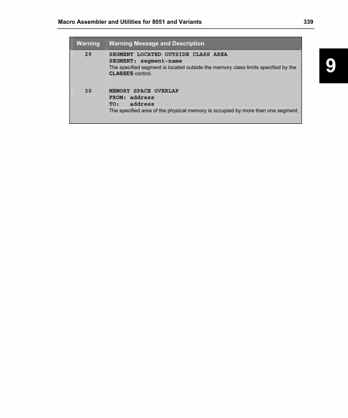
Macro Assembler and Utilities for 8051 and Variants 339
9
Warning Warning Message and Description
29 SEGMENT LOCATED OUTSIDE CLASS AREASEGMENT: segment-nameThe specified segment is located outside the memory class limits specified by the CLASSES control.
30 MEMORY SPACE OVERLAPFROM: addressTO: addressThe specified area of the physical memory is occupied by more than one segment.

340 Chapter 9. Linker/Locator
9
Non-Fatal Errors
Error Error Message and Description
101 SEGMENT COMBINATION ERRORSEGMENT: segment-nameMODULE: filename (modulename)The attributes of the specified partial segment in the specified module cannot be combined with the attributes of the previous defined partial segments of the same name. The partial segment is ignored.
102 EXTERNAL ATTRIBUTE MISMATCHSYMBOL: external-nameMODULE: filename (modulename)The attributes of the specified external symbol in the specified module do not match the attributes of the previously defined external symbols. The specified symbol is ignored.
103 EXTERNAL ATTRIBUTE DO NOT MATCH PUBLICSYMBOL: public-nameMODULE: filename (modulename)The attributes of the specified public symbols in the specified module do not match the attributes of the previous defined external symbols. The specified symbol is ignored.
104 MULTIPLE PUBLIC DEFINITIONSSYMBOL: public-nameMODULE: filename (modulename)The specified public symbol in the specified module has already been defined in a previously processed file.
105 PUBLIC REFERS TO IGNORED SEGMENTSYMBOL: public-nameSEGMENT: segment-nameThe specified public symbol is defined in the specified segment. It cannot be processed on account of an error. The public symbol is therefore ignored.
106 SEGMENT OVERFLOWSEGMENT: segment-nameThe specified segment is longer than the limits implied by the memory class to which the segment belongs to.
107 ADDRESS SPACE OVERFLOWSPACE: space-nameSEGMENT: segment-nameThe specified segment cannot be located at the specified address space. The segment is ignored.

Macro Assembler and Utilities for 8051 and Variants 341
9
Error Error Message and Description
108 SEGMENT IN LOCATING CONTROL CANNOT BE ALLOCATEDSEGMENT: segment-nameThe specified segment in the invocation line cannot be processed on account of its attributes.
109 EMPTY RELOCATABLE SEGMENTSEGMENT: segment-nameThe specified segment after combination has a zero size. The specified segment is ignored.
110 CANNOT FIND SEGMENTSEGMENT: segment-nameThe specified segment is contained in the invocation line but cannot be found in an input module. The specified segment is ignored.
111 SPECIFIED BIT ADDRESS NOT ON BYTE BOUNDARYSEGMENT: segment-nameThe specified segment contained in the BIT control is a DATA segment. The specified BIT address however is not on a byte boundary. The segment is ignored.
112 SEGMENT TYPE NOT LEGAL FOR COMMANDSEGMENT: segment-nameThe specified segment cannot be processed because it does not have a legal type.
113 SEGMENT IN LOCATING CONTROL IS ALREADY ABSOLUTESEGMENT: segment-nameThe specified segment is already an absolute segment and cannot be located with the SEGMENTS control.
114 SEGMENT DOES NOT FITSPACE: space-nameSEGMENT: segment-nameBASE: base-addressLENGTH: segment-lengthThe specified segment cannot be located at the base address in the specified address space because of its length. The segment is ignored.
115 INPAGE SEGMENT IS GREATER THAN 256 BYTESSEGMENT: segment-nameThe specified segment with the attributes PAGE or INPAGE is greater than 256 bytes. The segment is ignored.

342 Chapter 9. Linker/Locator
9
Error Error Message and Description
116 INBLOCK SEGMENT IS GREATER THAN 2048 BYTESSEGMENT: segment-nameThe specified segment with the attribute INBLOCK is greater than 2048 bytes. The segment is ignored.
117 BIT ADDRESSABLE SEGMENT IS GREATER THAN 16 BYTESSEGMENT: segment-nameThe specified bit or data segment that was declared with the BITADDRESSABLE attribute is larger than 16 bytes. The segment is not ignored.
118 REFERENCE MADE TO ERRONEOUS EXTERNALSYMBOL: symbol-nameMODULE: filename (modulename)ADDRESS: code-addressThe specified external symbol that was erroneously processed, is referenced in the specified code address.
119 REFERENCE MADE TO ERRONEOUS SEGMENTSEGMENT: symbol-nameMODULE: filename (modulename)ADDRESS: code-addressThe specified segment processed with an error, is referenced in the specified code address.
120 CONTENT BELONGS TO ERRONEOUS SEGMENTSEGMENT: segment-nameMODULE: filename (modulename)A specified segment that was erroneously processed, is referenced at a specific code address. The segment contents are not available.
121 IMPROPER FIXUPMODULE: filename (modulename)SEGMENT: segment-nameOFFSET: segment-addressAfter evaluation of absolute fixups, an address is not accessible. The improper address along with the specific module name, partial segment, and segment address are displayed. The fixup command is not processed. This error occurs when an instruction cannot reach the address, i.e. ACALL instruction calls a location outside the 2KB block. If you are working with the Cx51 compiler, you have typically selected the ROM(SMALL) option for a program that exceeds the 2KB ROM size. You can locate the instruction, when you open the LST file of the translator and search for the instruction that is located in the offset of the specified segment.
122 CANNOT FIND MODULEMODULE: filename (modulename)The module specified in the invocation line cannot be found in the input file.

Macro Assembler and Utilities for 8051 and Variants 343
9
Error Error Message and Description
123 ABSOLUTE DATA/IDATA SEGMENT DOES NOT FITMODULE: filename (modulename)FROM: byte addressTO: byte addressAn absolute DATA or IDATA segment contained in the specified module is not permissible due to a conflict with the value specified with the RAMSIZE control. The absolute segment cannot be located in the area, which was output.
124 BANK SWITCH MODULE INCORRECTThis error message is issued when the bank switch module file (L51_BANK.OBJ) contains invalid information or is not specified.
125 DUPLICATE TASK NUMBERTASK1: function nameTASK2: function nameTASKID: task-idA task number has been assigned to more than one RTXx51 task function.
126 TASK WITH PRIORITY 3 CANNOT WORK WITH REGISTERBANK 0TASK: function nameTASKID: task-idA task that has priority 3 must have a using attribute that refers to registerbank 1, 2, or 3.
127 UNRESOLVED EXTERNAL SYMBOLSYMBOL: external-nameMODULE: filename (modulename)The specified external symbol, requested in the specified module, has no corresponding PUBLIC symbol in any of the input files.
128 REFERENCE MADE TO UNRESOLVED EXTERNALSYMBOL: external-nameMODULE: filename (modulename)ADDRESS: code-addressThe specified unresolved external symbol is referenced at the specified code address.
129 TASK REQUIRES REGISTERBANKTASK: function nameTASKID: task-idThe task function requires that you assign a registerbank with an using attribute.
130 NO MATCHING SEGMENT FOR WILDCARD SEGMENT NAMESEGMENT: segment-nameThe linker could not find a segment name that matches the wildcard segment name stated in the command line.

344 Chapter 9. Linker/Locator
9
Error Error Message and Description
131 LLEGAL PRIORITY FOR TASKTASK: function nameTASKID: task-idYou have assigned a priority for an RTX51 Tiny task. RTX51 Tiny does not support priorities.
132 ILLEGAL TASKID: RTX-51 TINY SUPPORTS ONLY 16 TASKSTASK: function nameTASKID: task-idYou have assigned a task-id that is higher than 15. RTX51 Tiny tasks supports only 16 tasks.
133 SFR SYMBOL HAS DIFFERENT VALUESSYMBOL: public-nameMODULE: filename (modulename)The specified SFR symbol is defined with different values in several input modules.
134 ADDRESS SPACE OVERFLOW IN BANKAREASPACE: space-nameSEGMENT: segment-nameThe specified segment cannot be located in the banked area, since the banked area is already full.
Fatal Errors
Error Error Message and Description
201 INVALID COMMAND LINE SYNTAXA syntax error is detected in the command line. The command line is displayed up to and including the point of error.
202 INVALID COMMAND LINE, TOKEN TOO LONGThe command line contains a token that is too long. The command line is displayed up to and including the point of error.
203 EXPECTED ITEM MISSINGAn expected item is missing in the command line. The command line is displayed up to and including the point of error.
204 INVALID KEYWORDThe invocation line contains an invalid keyword. The command line is displayed up to and including the point of error.
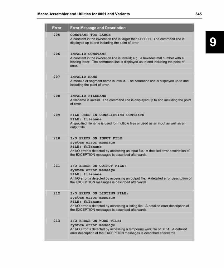
Macro Assembler and Utilities for 8051 and Variants 345
9
Error Error Message and Description
205 CONSTANT TOO LARGEA constant in the invocation line is larger than 0FFFFH. The command line is displayed up to and including the point of error.
206 INVALID CONSTANTA constant in the invocation line is invalid; e.g., a hexadecimal number with a leading letter. The command line is displayed up to and including the point of error.
207 INVALID NAMEA module or segment name is invalid. The command line is displayed up to and including the point of error.
208 INVALID FILENAMEA filename is invalid. The command line is displayed up to and including the point of error.
209 FILE USED IN CONFLICTING CONTEXTSFILE: filenameA specified filename is used for multiple files or used as an input as well as an output file.
210 I/O ERROR ON INPUT FILE:system error messageFILE: filenameAn I/O error is detected by accessing an input file. A detailed error description of the EXCEPTION messages is described afterwards.
211 I/O ERROR ON OUTPUT FILE:system error messageFILE: filenameAn I/O error is detected by accessing an output file. A detailed error description of the EXCEPTION messages is described afterwards.
212 I/O ERROR ON LISTING FILE:system error messageFILE: filenameAn I/O error is detected by accessing a listing file. A detailed error description of the EXCEPTION messages is described afterwards.
213 I/O ERROR ON WORK FILE:system error messageAn I/O error is detected by accessing a temporary work file of BL51. A detailed error description of the EXCEPTION messages is described afterwards.

346 Chapter 9. Linker/Locator
9
Error Error Message and Description
214 INPUT PHASE ERRORMODULE: filename (modulename)This error occurs when BL51 encounters different data during pass two. This error could be the result of an assembly error.
215 CHECK SUM ERRORMODULE: filename (modulename)The checksum does not correspond to the contents of the file.
216 INSUFFICIENT MEMORYThe memory available for the execution of BL51 is used up.
217 NO MODULE TO BE PROCESSEDNo module to be processed is found in the invocation line.
218 NOT AN OBJECT FILEFILE: filenameThe specified file is not an object file.
219 NOT AN 8051/X51 OBJECT FILEFILE:filenameThe specified file is not a valid x51 object file.
220 INVALID INPUT MODULEFILE: filenameThe specified input module is invalid. This error could be the result of an assembler error.
221 MODULE SPECIFIED MORE THAN ONCEThe invocation line contains the specified module more than once. The command line is displayed up to and including the point of error.
222 SEGMENT SPECIFIED MORE THAN ONCEThe invocation line contains the specified segment more than once. The command line is displayed up to and including the point of error.
224 DUPLICATE KEYWORD OR CONFLICTING CONTROLThe same keyword is contained in the invocation line more than once or contradicts with other keywords. The command line is displayed up to and including the point of error.
225 SEGMENT ADDRESS ARE NOT IN ASCENDING ORDERThe base addresses for the segments are not displayed in ascending order during the location control. The command line is displayed up to and including the point of error.

Macro Assembler and Utilities for 8051 and Variants 347
9
Error Error Message and Description
226 SEGMENT ADDRESS INVALID FOR CONTROLThe base addresses for the segments are invalid for the location control. The command line is displayed up to and including the point of error.
227 PARAMETER OUT OF RANGEThe specified value for the PAGEWIDTH or PAGELENGTH control is out of the acceptable range. The command line is displayed up to and including the point of error.
228 RAMSIZE PARAMETER OUT OF RANGEThe specified value for the RAMSIZE control is out of the acceptable range. The command line is displayed up to and including the point of error.
229 INTERNAL PROCESS ERRORLx51 detects an internal processing error. Please contact your dealer.
230 START ADDRESS SPECIFIED MORE THAN ONCEThe invocation line contains more than one start address for unnamed segment group. The command is displayed up to and including the point of error.
231 ADDRESS RANGE FOR BANKAREA INCORRECTThe address space specified with the BANKAREA control is invalid.
232 APPLICATION CONTAINS TOO MANY RECURSIONSThe application contains to many recursive calls. Refer to “RECURSIONS” on page 331 for more information.
233 ILLEGAL USE OF * IN OVERLAY CONTROLThe use of “* ! *” or “* ~ *” with the OVERLAY control is illegal.
234 USE RTX251 OR RTX51 CONTROLThe application uses RTXx51 tasks mented.
233 ILLEGAL USE OF * IN OVERLAY CONTROLcommand lineThe use of “* ! *” or “* ~ *” with the OVERLAY control is illegal.
234 USE RTX-251 SWITCHThe application uses a real-time operating system RTX251 Full or RTX251 Tiny. The L251 linker/locater must be invoked with the RTX251 or RTX251TINY control.
235 TOO MANY ADDRESS RANGESYou are using to many address ranges.

348 Chapter 9. Linker/Locator
9
Error Error Message and Description
236 ADDRESSES ARE NOT IN ASCENDING ORDERThe address range does not contain addresses in ascending order.
237 INVALID CLASS NAMEThe class name given in the CLASSES control is not valid.
238 BIT ADDRESS INVALID FOR THIS CLASS TYPEThe CLASSES control contains a bit address for a memory class which cannot be used for bit objects.
239 BASE ADDRESS ALREADY GIVEN FOR THIS CLASSThe CLASSES control contains a base address, but the class has already a base address specified with a previous CLASSES control.
240 BASE ADDRESS MUST BE THE FIRST ARGUMENTThe base address must be the first argument in the CLASSES control.
241 BASE ADDRESS CANNOT BE GIVEN FOR THIS CLASSA base address cannot be given for this memory class in the CLASSES control.
242 WRONG SYNTAX FOR THE EXECUTION ADDRESSThe execution address field contains a wrong syntax.
243 EXECUTION ADDRESS REQUIRED IF SPACE IS NOT RESERVEDYou need to specify an execution address, if the execution space should not be reserved.
244 OVERLAPPING CLASS RANGEThe address ranges in the classes control are overlapping.
245 ADDRESS RANGE INVALID FOR THIS CLASS TYPEThe address range given in the CLASSES control is not valid for this memory class type.
246 SYMBOL SPECIFIED MORE THAN ONCEThe symbol name is already used.
249 MODULE USES AN UNKNOWN OMF VERSIONMODULE: filename (modulename)The module uses an un-known or unsupported OMF version.
250 CODE SIZE LIMIT IN RESTRICTED VERSION EXCEEDEDYou are using modules that are created with an evaluation version or a code size limited version and the size limit is exceeded.
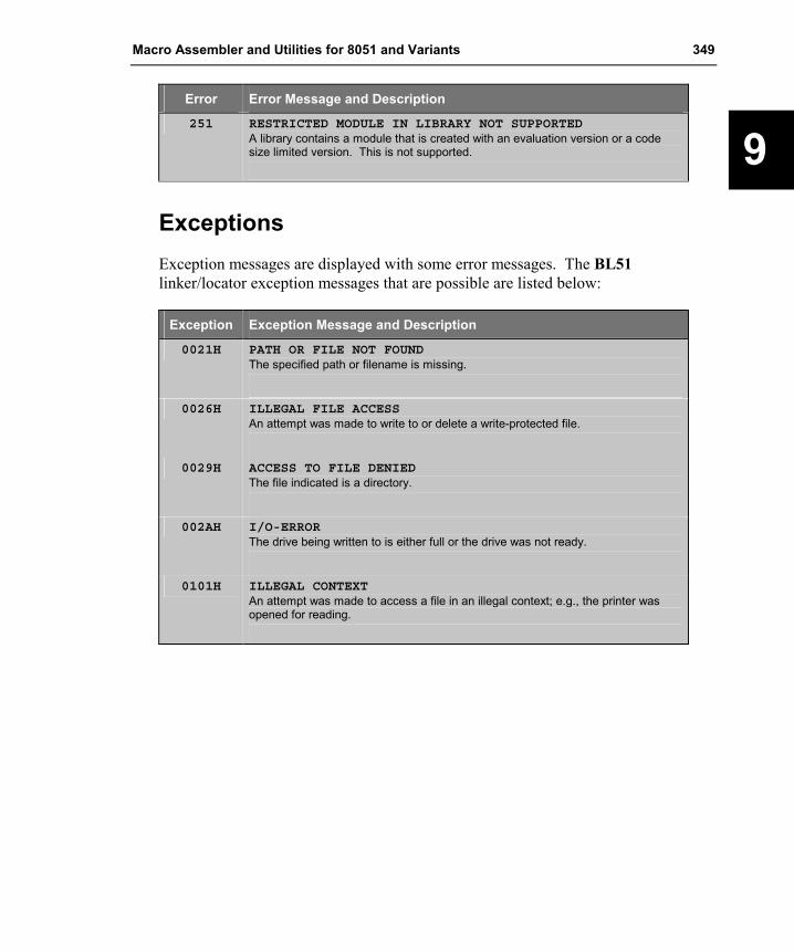
Macro Assembler and Utilities for 8051 and Variants 349
9
Error Error Message and Description
251 RESTRICTED MODULE IN LIBRARY NOT SUPPORTEDA library contains a module that is created with an evaluation version or a code size limited version. This is not supported.
Exceptions Exception messages are displayed with some error messages. The BL51 linker/locator exception messages that are possible are listed below:
Exception Exception Message and Description
0021H PATH OR FILE NOT FOUNDThe specified path or filename is missing.
0026H ILLEGAL FILE ACCESS
An attempt was made to write to or delete a write-protected file.
0029H ACCESS TO FILE DENIED
The file indicated is a directory.
002AH I/O-ERROR
The drive being written to is either full or the drive was not ready.
0101H ILLEGAL CONTEXT
An attempt was made to access a file in an illegal context; e.g., the printer was opened for reading.


Macro Assembler and Utilities for 8051 and Variants 351
10
Chapter 10. Library Manager The LIBx51 library manager allows you to create and maintain library files. A library file is a formatted collection of one or more object files. Library files provide a convenient method of referencing a large number of object files and can be used by the Lx51 linker/locator. The LIBx51 library manager can be controlled interactively or from the command line.
The following table gives you an overview of the LIBx51 library manager variants along with the translators that are supported.
Library Manager Processes Files from… Description
LIB51 Keil A51 Macro Assembler Keil C51 Compiler Intel ASM51 Assembler Intel PL/M51 Compiler
For classic 8051. Includes support for 32 x 64KB code banks.
LIBX51 Keil A51 Macro Assembler Keil C51 Compiler Keil AX51 Macro Assembler Keil CX51 Compiler for 80C51MX Intel ASM51 Assembler Intel PL/M51 Compiler
For classic 8051 and extended 8051 versions (Philips 80C51MX, Dallas 390, ect.) Allows code and data banking and supports up to 16MB code and xdata memory.
LIB251 Keil A51 Macro Assembler Keil C51 Compiler Keil A251 Macro Assembler Keil C251 Compiler Intel ASM51 Assembler Intel PL/M51 Compiler
For Intel/Temic 251.

352 Chapter 10. Library Manager
10
Using LIBx51 To invoke the LIBx51 library manager from the command prompt, type the program name along with an optional command. The format for the LIBx51 command line is:
LIB51 �command�
LIBX51 �command�
LIB251 �command�
or LIB51 @commandfileLIBX51 @commandfileLIB251 @commandfile
where
command may be a single library manager command.
commandfile is the name of a command input file that may contain a very long library manager command.
Interactive Mode If no command is entered on the command line, or if the ampersand character is included at the end of the line, the LIB51 library manager enters interactive mode. The LIBx51 library manager displays an asterisk character (*) to signal that it is in interactive mode and is waiting for input.
Any of the LIBx51 library manager commands may be entered on the command line or after the * prompt when in interactive mode.
Type EXIT to leave the LIBx51 library manager interactive mode.
Create Library within µVision2 You can directly create a library file from your µVision2 project. Select Create Library in the dialog Options for Target – Output. µVision2 will call the correct LIBx51 Library Manager instead of the Lx51 Linker/Locater. Since the code in the Library will be not linked and located, the entries in the L51 Locate and L51 Misc options page are ignored.

Macro Assembler and Utilities for 8051 and Variants 353
10
Command Summary The following table lists the commands that are available for the LIBx51 library manager. The usage and the syntax of these commands are described in the sections that follow.
NOTE Underlined characters denote the abbreviation for the particular command.
LIBx51 Command Description
ADD Adds an object module to the library file. For example, LIB51 ADD GOODCODE.OBJ TO MYLIB.LIBadds the GOODCODE.OBJ object module to MYLIB.LIB.
CREATE Creates a new library file. For example, LIB251 CREATE MYLIB.LIBcreates a new library file named MYLIB.LIB.
DELETE Removes an object module from the library file. For example, LIBX51 DELETE MYLIB.LIB (GOODCODE)removes the GOODCODE module from MYLIB.LIB.
EXTRACT Extracts an object module from the library file. For example, LIB251 EXTRACT MYLIB.LIB (GOODCODE) TO GOOD.OBJcopies the GOODCODE module to the object file GOOD.OBJ.
EXIT Exits the library manager interactive mode.
HELP Displays help information for the library manager.
LIST Lists the module and public symbol information stored in the library file. For example, LIB251 LIST MYLIB.LIB TO MYLIB.LST PUBLICSgenerates a listing file (named MYLIB.LST) that contains the module names stored in the MYLIB.LIB library file. The PUBLICS directive specifies that public symbols are also included in the listing.
REPLACE Replaces an existing object module to the library file. For example, LIB51 REPLACE GOODCODE.OBJ IN MYLIB.LIBreplaces the GOODCODE.OBJ object module in MYLIB.LIB. Note that Replace will add GOODCODE.OBJ to the library if it does not exist.
TRANSFER Generates a complete new library and adds object modules. For example, LIB251 TRANSFER FILE1.OBJ, FILE2.OBJ TO MYLIB.LIBdeletes the existing library MYLIB.LIB, re-creates it and adds the object modules FILE1.OBJ and FILE2.OBJ to that library.

354 Chapter 10. Library Manager
10
Creating a Library The CREATE command creates a new, empty library file and has the following format:
CREATE libfile
libfile is the name of the library file to create and should include a file extension. Usually, .LIB is the extension that is used for library files.
Example: LIBX51 CREATE MYFILE.LIB
* CREATE FASTMATH.LIB
The TRANSFER command creates a new library file and adds object modules. The TRANSFER command must be entered in the following format:
TRANSFER filename �(modulename, …)� �, …� TO libfile
where
filename is the name of an object file or library file. You may specify several files separated by a comma.
modulename is the name of a module in a library file. If you do not want to add the entire contents of a library, you may select the modules that you want to add. Module names are specified immediately following the filename, must be enclosed in parentheses, and must be separated by commas.
libfile is the name of the library file that should be created. The LIBx51 library manager will remove a previous version of the library, if this file already exists. The specified object modules are added to the new created library.
Example: LIB251 TRANSFER FILE1.OBJ, FILE2.OBJ TO MYLIB.LIB
LIBX51 @mycmd.lin
--- content of mycmd.lin: ---TRANSFER FILE1.OBJ, FILE2.OBJ, FILE3.OBJ TO MYLIB.LIB

Macro Assembler and Utilities for 8051 and Variants 355
10
Adding or Replacing Object Modules The ADD command is used to add one or more object modules to an existing library file. The ADD command must be entered in the following format:
ADD filename �(modulename, …)� �, …� TO libfile
where
filename is the name of an object file or library file. You may specify several files separated by a comma.
modulename is the name of a module in a library file. If you do not want to add the entire contents of a library, you may select the modules that you want to add. Module names are specified immediately following the filename, must be enclosed in parentheses, and must be separated by commas.
libfile is the name of an existing library file. The specified object modules are added to this library.
Example: LIB51 ADD MOD1.OBJ, UTIL.LIB(FPMUL, FPDIV) TO NEW.LIB
* ADD FPMOD.OBJ TO NEW.LIB
With the REPLACE command you can update an existing object module in a library file. The REPLACE command will the object module to the library if it does not exist. The format is:
REPLACE filename IN libfile
where
filename is the name of an object file you want to update.
libfile is the name of an existing library file. The object module is replaced in this library.
Example: LIBX51 REPLACE MOD1.OBJ IN MYLIB.LIB
* REPLACE FPMOD.OBJ TO FLOAT.LIB

356 Chapter 10. Library Manager
10
Removing Object Modules The DELETE command removes object modules from a library file. This command must be entered in the following format:
DELETE libfile (modulename �, modulename …�)
where
libfile is the name of an existing library file. The specified object modules are removed from this library.
modulename is the name of a module in the library file that you want to remove. Module names are entered in parentheses and are separated by commas.
Example: LIB51 DELETE NEW.LIB (MODUL1)
* DELETE NEW.LIB (FPMULT, FPDIV)
Extracting Object Modules The EXTRACT command creates a standard object module for a specified module in a library file. This command must be entered in the following format:
EXTRACT libfile (modulename) TO filename
where
libfile is the name of an existing library file. For the specified object module a standard object module will be created.
modulename is the name of a module in the library file. Only one module name can be entered in parentheses.
filename is the name of the object file that should be created from the library module.
Example: LIBX51 EXTRACT FLOAT.LIB(FPMUL) TO FLOATMUL.OBJ

Macro Assembler and Utilities for 8051 and Variants 357
10
Listing Library Contents Use the LIST command to direct the LIBx51 library manager to generate a listing of the object modules that are stored in a library file. LIST may be specified on the command line or after the * prompt in interactive mode. This command has the following format:
LIST libfile �TO listfile� �PUBLICS�
where
libfile is the library file from which a module list is generated.
listfile is the file where listing information is written. If no listfile is specified, the listing information is displayed on the screen.
PUBLICS specifies that public symbols are included in the listing. Normally, only module names are listed.
Example: LIB251 LIST NEW.LIB
* LIST NEW.LIB TO NEW.LST PUBLICS
The LIBx51 library manager produces a module listing that appears as follows:
LIBRARY: NEW.LIBPUTCHAR
_PUTCHARPRINTF
?_PRINTF517?BYTE?_SPRINTF517?BYTE?_PRINTF?BYTE?_SPRINTF?BYTE_PRINTF_SPRINTF_PRINTF517_SPRINTF517
PUTS_PUTS
In this example, PUTCHAR, PRINTF, and PUTS are module names. The names listed below each of these module names are public symbols found in each of the modules.

358 Chapter 10. Library Manager
10
Error Messages This chapter lists the fatal and non-fatal errors that may be generated by the LIB51 library manager during execution. Each section includes a brief description of the message, as well as corrective actions you can take to eliminate the error or warning condition.
Fatal Errors Fatal errors cause immediate termination of the LIB51 library manager. These errors normally occur as the result of a corrupt library or object file, or as a result of a specification problem involving library or object files.
Error Error Message and Description
215 CHECK SUM ERRORFILE: filenameThe checksum for filename is incorrect. This usually indicates a corrupt file.
216 INSUFFICIENT MEMORYThere is not enough memory for the LIB51 library manager to successfully complete the requested operation.
217 NOT A LIBRARYFILE: filenameThe filename that was specified is not a library file.
219 NOT AN 8051 OBJECT FILEFILE: filenameThe filename that was specified is not a valid 8051 object file.
222 MODULE SPECIFIED MORE THAN ONCEMODULE: filename (modulename)The specified modulename is included on the command line more than once.
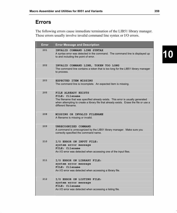
Macro Assembler and Utilities for 8051 and Variants 359
10
Errors The following errors cause immediate termination of the LIB51 library manager. These errors usually involve invalid command line syntax or I/O errors.
Error Error Message and Description 201 INVALID COMMAND LINE SYNTAX
A syntax error was detected in the command. The command line is displayed up to and including the point of error.
202 INVALID COMMAND LINE, TOKEN TOO LONGThe command line contains a token that is too long for the LIB51 library manager to process.
203 EXPECTED ITEM MISSINGThe command line is incomplete. An expected item is missing.
205 FILE ALREADY EXISTSFILE: filenameThe filename that was specified already exists. This error is usually generated when attempting to create a library file that already exists. Erase the file or use a different filename.
208 MISSING OR INVALID FILENAMEA filename is missing or invalid.
209 UNRECOGNIZED COMMANDA command is unrecognized by the LIB51 library manager. Make sure you correctly specified the command name.
210 I/O ERROR ON INPUT FILE:system error messageFILE: filenameAn I/O error was detected when accessing one of the input files.
211 I/O ERROR ON LIBRARY FILE:system error messageFILE: filenameAn I/O error was detected when accessing a library file.
212 I/O ERROR ON LISTING FILE:system error messageFILE: filenameAn I/O error was detected when accessing a listing file.

360 Chapter 10. Library Manager
10
Error Error Message and Description 213 I/O ERROR ON TEMPORARY FILE:
system error messageFILE: filenameAn I/O error was detected when a temporary file was being accessed.
220 INVALID INPUT MODULEFILE: filenameThe specified input module is invalid. This error could be the result of an assembler error or could indicate that the input object file is corrupt.
221 FILE SPECIFIED MORE THAN ONCEFILE: filenameThe filename specified was included on the command line more than once.
223 CANNOT FIND MODULEMODULE: filename (modulename)The modulename specified on the command line was not located in the object or library file.
224 ATTEMPT TO ADD DUPLICATE MODULEMODULE: filename (modulename)The specified modulename already exists in the library file and cannot be added.
225 ATTEMPT TO ADD DUPLICATE PUBLIC SYMBOLMODULE: filename (modulename)PUBLIC: symbolnameThe specified public symbolname in modulename already exists in the library file and cannot be added.

Macro Assembler and Utilities for 8051 and Variants 361
11
Chapter 11. Object-Hex Converter Program code stored in an absolute object file can be converted an Intel HEX file. Intel HEX files may be used as input files for EPROM programmers or emulators.
For the each Lx51 linker/locater variant a different OHx51 object hex converter is required to create an Intel HEX file. For code banking applications generated with the BL51 linker/locater, you need in addition the OC51 Banked Object File Converter to create HEX files. The following table gives you an overview of the conversion tools required to create an Intel HEX file.
Output from… Object Hex Converter Description
BL51 OH51 For classic 8051 applications without banking.
BL51 Banked Application
OC51 combined with OH51
For classic 8051 applications with banking.
LX51 OHX51 For classic 8051 and extended 8051 versions.
L251 OH251 For Intel/Temic 251. In µVision2 you enable the generation of an Intel Object file in the dialog Options – Output with
Create HEX File. The µVision2 project manager selects automatically the correct utility.
The following sections describe how to use the OHx51 and OC51 utilities, the command-line options that are available, and any errors that may be encountered during execution.
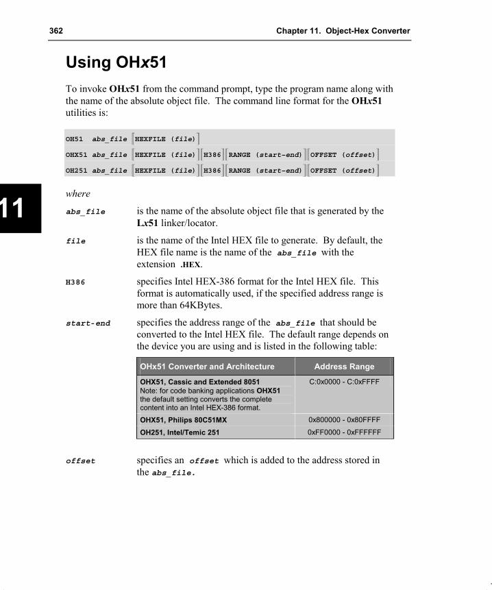
362 Chapter 11. Object-Hex Converter
11
Using OHx51 To invoke OHx51 from the command prompt, type the program name along with the name of the absolute object file. The command line format for the OHx51 utilities is:
OH51 abs_file �HEXFILE (file)�
OHX51 abs_file �HEXFILE (file)��H386��RANGE (start–end)��OFFSET (offset)�
OH251 abs_file �HEXFILE (file)��H386��RANGE (start–end)��OFFSET (offset)�
where
abs_file is the name of the absolute object file that is generated by the Lx51 linker/locator.
file is the name of the Intel HEX file to generate. By default, the HEX file name is the name of the abs_file with the extension .HEX.
H386 specifies Intel HEX-386 format for the Intel HEX file. This format is automatically used, if the specified address range is more than 64KBytes.
start-end specifies the address range of the abs_file that should be converted to the Intel HEX file. The default range depends on the device you are using and is listed in the following table:
OHx51 Converter and Architecture Address Range
OHX51, Cassic and Extended 8051 Note: for code banking applications OHX51 the default setting converts the complete content into an Intel HEX-386 format.
C:0x0000 - C:0xFFFF
OHX51, Philips 80C51MX 0x800000 - 0x80FFFF
OH251, Intel/Temic 251 0xFF0000 - 0xFFFFFF
offset specifies an offset which is added to the address stored in the abs_file.

Macro Assembler and Utilities for 8051 and Variants 363
11
OHx51 Command Line Examples The following command generates an Intel HEX-386 file for a 251 device. The address range 0xFE0000 - 0xFFFFFF should be converted. The offset 0xFE0000 is subtracted to get an Intel HEX file that can be directly programmed into an EPROM that is mapped to the address space 0xFE0000 - 0xFFFFFF in the 251 address space.
OH251 MYPROG RANGE (0xFE0000-0xFFFFFF) OFFSET (-0xFE0000)
The next example generates an Intel HEX file for a banked application with a classic 8051 device. Only the code bank 0 should be converted. The file format used will be the standard Intel HEX format.
OHX51 PROG RANGE (B:0-B:0xFFFF)
The command below generates an Intel HEX-386 file for a Philips 80C51MX device. The OFFSET control is used to create an output file that can be directly programmed into an EPROM.
OHX51 MYAPP RANGE (0x800000-0x81FFFF) OFFSET (-0x800000)
With the next command line, the constants stored in the XDATA space are converted into an Intel HEX file.
OHX51 MYPROG RANGE (X:0-X:FFFF)
Creating HEX Files for Banked Applications For the BL51 linker/locater the OC51 Banked Object File Converter described on page 366 is used to split banked object files into standard object files that contain a 64KB code bank. These files can be converted with OH51 into HEX files that store the content of a 64KB bank. These files are programmed separately into the corresponding physical address space of the EPROM.
For the extended LX51 linker/locater the OHX51 object hex converter generates in the default setting and Intel HEX-386 file that contains the common area and all the code banks. If code bank 0 does not exist in your application, OHX51 will skip this memory area.
Examples:
The figure below shows the HEX file content for the example
The following figure shows the HEX file content for the example

364 Chapter 11. Object-Hex Converter
11
“Banking With Four 64 KByte Banks” on page 274.
0
10000H
20000H
30000H
Code Bank #0
Code Bank #2
Code Bank #1
Code Bank #3
“Banking With Common Area” on page 278.
0
8000H
10000H
18000H
20000H
28000H
30000H
38000H
Common Area
Code Bank #1
Code Bank #5
Code Bank #4
Code Bank #3
Code Bank #2
Code Bank #6
Code Bank #7
OHx51 Error Messages The following tables list error and warning messages of OHx51. Each message includes a brief description of the reason for the error or warning condition.
Error Message
*** ERROR, INVALID RECORD-TYPE ENCOUNTEREDThe absolute object file contains an invalid record type. *** FATAL, INCONSISTENT OBJECT FILEThe input file has an invalid format. *** ERROR, ARGUMENT TOO LONGAn argument in the command line is too long. *** ERROR, DELIMITER '(' AFTER PARAMETER EXPECTEDThe command-line parameter must be followed by an argument enclosed in parentheses (). *** ERROR, DELIMITER ')' AFTER PARAMETER EXPECTEDThe command-line parameter must be followed by an argument enclosed in parentheses (). *** ERROR, UNKNOWN CONTROL:The specified command-line parameter is unrecognized. *** ERROR, RESPECIFIED CONTROL, IGNOREDThe indicated command-line control was specified twice. *** ERROR, CAN’T OPEN FILE filenameThe specified file cannot be open for read. *** ERROR, CAN’T CREATE FILE filenameThe specified file cannot be open for write. *** I/O-ERROR ON FILE filenameA read/write error occurred during access of the specified file.

Macro Assembler and Utilities for 8051 and Variants 365
11
Error Message
*** ERROR: PREMATURE END OF FILE ON filenameThe input file does not end correctly. This is usually a result of a previous fatal error of an translator or linker/locater. *** ERROR: MORE THAN 512 CLASSES ON filenameThe input file contains more than 512 memory classes. This is the limit of OHx51. *** ERROR, NON-NULL ARGUMENT EXPECTEDAn argument is missing.
Warning Message
WARNING: <PUBDEF> HEX-FILE WILL BE INVALIDThe absolute object file still contains public definitions. This warning usually indicates that the object file has not been processed by the Lx51 linker/locator. The hex file that is produced may be invalid. WARNING: <EXTDEF> UNDEFINED EXTERNALThe absolute object file still contains external definitions. This warning usually indicates that the object file has not been processed by the Lx51 linker/locator. The hex file that is produced may be invalid. WARNING: <FIXUPP> HEX-FILE WILL BE INVALIDThe absolute object file still contains fixups. This warning usually indicates that the object file has not been processed by the L251 linker/locator. The hex file that is produced may be invalid.

366 Chapter 11. Object-Hex Converter
11
Using OC51 The BL51 linker/locator generates a banked object file for programs that use bank switching. Banked object files contain several banks of code that reside at the same physical location. These object files can be converted into standard object files using the OC51 Banked Object File Converter.
The OC51 Banked Object File Converter will create an absolute object file for each code bank represented in the banked object file. Symbolic debugging information that was included in the banked object file will be copied to the absolute object modules that are generated. Once you have created absolute object files with OC51, you may use the OH51 Object-Hex Converter to create Intel HEX files for each absolute object file.
The OC51 Banked Object File Converter is invoked from the command prompt by typing OC51 along with the name of the banked object file. The command line format is:
OC51 banked_obj_file
where
banked_obj_file is the name of the banked object file that is generated by the BL51 linker/locator.
OC51 will create separate absolute object modules for each code bank represented in the banked object file. The absolute object modules will be created with a filename consisting of the basename of the banked object file combined with the file extension Bnn where nn corresponds to the bank number 00 - 31. For example:
OC51 MYPROG
creates the absolute object files MYPROG.B00 for code bank 0, MYPROG.B01 for code bank 1, MYPROG.B02 for code bank 2, etc.
NOTE Use the OC51 Banked Object File Converter only if you used the BANKx control on the BL51 linker/locator command line. If your program does not use code banking, do not use OC51.

Macro Assembler and Utilities for 8051 and Variants 367
11
OC51 Error Messages The following table lists the errors that you may encounter when you use the OC51 Banked Object File Converter. Each message includes a brief description of the message as well as corrective actions you can take to eliminate the error condition.
Error Error Message and Description
201 FILE ACCESS ERROR ON INPUT FILEFILE: filenameAn error occurred while reading the specified file.
202 FILE ACCESS ERROR ON OUTPUT FILEFILE: filenameAn error occurred while writing the specified file.
203 NOT A BANKED 8051 OBJECT FILEThe input file is not a banked object file.
204 INVALID INPUT FILEThe input file has an invalid format.
205 CHECKSUM ERRORThe input file has an invalid checksum. This error is usually caused by an error from BL51. Make sure that your program was linked successfully.
206 INTERNAL ERROROC51 has detected an internal error. Contact technical support.
207 SCOPE LEVEL ERRORMODULE: modulenameThe symbolic information in the specified file contains errors. This error message is usually the result of an error at link time. Make sure that your program was linked successfully.
208 PATH OR FILE NOT FOUNDFILE: filenameThe OC51 Banked Object File Converter cannot find the specified file. Make sure the file actually exists.

368 Chapter 11. Object-Hex Converter
11
Intel HEX File Format The Intel HEX file is an ASCII text file with lines of text that follow the Intel HEX file format. Each line in an Intel HEX file contains one HEX record. These records are made up of hexadecimal numbers that represent machine language code and/or constant data. Intel HEX files are often used to transfer the program and data that would be stored in a ROM or EPROM. Most EPROM programmers or emulators can use Intel HEX files.
Record Format An Intel HEX file is composed of any number of HEX records. Each record is made up of five fields that are arranged in the following format:
:llaaaatt�dd...�cc
Each group of letters corresponds to a different field, and each letter represents a single hexadecimal digit. Each field is composed of at least two hexadecimal digits—which make up a byte—as described below:
: is the colon that starts every Intel HEX record.
ll is the record-length field that represents the number of data bytes (dd) in the record.
aaaa is the address field that represents the starting address for subsequent data in the record.
tt is the field that represents the HEX record type, which may be one of the following: 00 data record 01 end-of-file record 02 extended 8086 segment address record. 04 extended linear address record.
dd is a data field that represents one byte of data. A record may have multiple data bytes. The number of data bytes in the record must match the number specified by the ll field.
cc is the checksum field that represents the checksum of the record. The checksum is calculated by summing the values of all hexadecimal digit pairs in the record modulo 256 and taking the two’s complement.

Macro Assembler and Utilities for 8051 and Variants 369
11
Data Record The Intel HEX file is made up of any number of data records that are terminated with a carriage return and a linefeed. Data records appear as follows:
:10246200464C5549442050524F46494C4500464C33
where:
10 is the number of data bytes in the record.
2462 is the address where the data are to be located in memory.
00 is the record type 00 (a data record).
464C...464C is the data.
33 is the checksum of the record.
End-of-File (EOF) Record An Intel HEX file must end with an end-of-file (EOF) record. This record must have the value 01 in the record type field. An EOF record always appears as follows:
:00000001FF
where:
00 is the number of data bytes in the record.
0000 is the address where the data are to be located in memory. The address in end-of-file records is meaningless and is ignored. An address of 0000h is typical.
01 is the record type 01 (an end-of-file record).
FF is the checksum of the record and is calculated as 01h + NOT(00h + 00h + 00h + 01h).
Extended 8086 Segment Record The Intel HEX contains extended 8086 segment records when the H86 directive is used. This record is used to specify an address offset (in 8086 paragraph form) for the following data records. Extended 8086 segment records appear as follows:

370 Chapter 11. Object-Hex Converter
11
:02000002F0000C
where:
02 is the number of data bytes in the record.
0000 is always 0 in a extended 8086 segment record.
02 is the record type 02 (a extended 8086 segment record).
F000 is the offset in 8086 paragraph notation (= 0x0F0000).
0C is the checksum of the record.
Extended Linear Address Record The Intel HEX contains extended linear address records when the H386 directive is used. This record is used to specify the two most significant bytes (bits 16 - 31) of the absolute address. This address offset is used for all following data records. Extended linear address records appear as follows:
:0200000400FFFB
where:
02 is the number of data bytes in the record.
0000 is always 0 in a extended 8086 segment record.
04 is the record type 04 (a extended linear address record).
00FF is the high word of the address offset (= 0xFF0000).
FB is the checksum of the record.
Example Intel HEX File Following is an example of a complete Intel HEX file:
:0200000400FFFB:03000000020003F8:10000300758107758920758DFDD28E759852C20052:0B00130090001E12003612002B80F53A:0D001E00544553542050524F4752414D005D:10002B00740D120047740A12004722200004E49357:0C003B008001E06006120047A380F02264:080047003099FDC299F59922E0:00000001FF

Macro Assembler and Utilities for 8051 and Variants 371
A
Appendix A. Application Examples This chapter illustrates project development for the x51 microcontroller family. The sample programs are found in the C:\KEIL\C51\EXAMPLES\ or C:\KEIL\C251\EXAMPLES\ folder. Each sample program is stored in a separate folder along with µVision2 project files that help you quickly build each sample program.
The following table lists the sample programs that are discussed in the following section and their folder names.
Example Description
ASM This section describes a short x51 program, developed in assembler language. The program displays the text "PROGRAM TEST" on the serial interface.
CSAMPLE Simple addition and subtraction calculator that shows how to build a C application.
BANK_EX1 C application for a classic 8051 device that shows code banking.
BANK_EX2 C program for a classic 8051 device that stores constants in different code banks.
BANK_EX3 Intel PL/M-51 application that uses code banking.
Philips 80C51MX \ASM
Assembler example that demonstrates the new instructions of the Philips 80C51MX.
Philips 80C51MX \Banking
C Compiler example that shows how to use the extended address space of the Philips 80C51MX.
The folder EXAMPLES contains several other example programs that are described in the µVision2 for the x51 Family User’s Guide.
ASM – Assembler Example This section shows you how to create a x51 program, developed in assembler language. The program outputs the text "PROGRAM TEST" on the serial interface. The program consists of three modules that can be translated using the various tool versions.
Using A51 and BL51 The following commands are required to translate and link the ASM example with the A51 macro assembler and the BL51 linker/locater. The output file can be converted into an Intel HEX file with the OH51 hex file converter.

372 Appendix A. Application Examples
A
A51 ASAMPLE1.A51 DEBUG XREFA51 ASAMPLE2.A51 DEBUG XREFA51 ASAMPLE3.A51 DEBUG XREF
The XREF control causes the A51 assembler to include in the listing (LST) files a cross reference report of the symbols used in the module. The DEBUG control includes complete symbol information in the object file.
After assembly, the files are linked by the BL51 linker/locator with:
BL51 ASAMPLE1.OBJ, ASAMPLE2.OBJ, ASAMPLE3.OBJ PRECEDE (VAR1) IXREF
In the above linker command line, the PRECEDE control locates the VAR1 segment before other internal data memory segments. The IXREF control includes a cross reference report of all public and external symbols in the linker listing (M51) file. The linker creates an absolute object module that is stored in the file ASAMPLE1. This file can be used as input for debuggers or may be used to create an Intel HEX file using the OH51 object hex converter with the following command:
OH51 ASAMPLE1
Using AX51 and LX51 The commands for translating the application with the AX51 macro assembler and the LX51 linker/locater are:
AX51 ASAMPLE1.A51 DEBUG XREFAX51 ASAMPLE2.A51 DEBUG XREFAX51 ASAMPLE3.A51 DEBUG XREF
After assembly, the files are linked by the LX51 linker/locator with:
LX51 ASAMPLE1.OBJ, ASAMPLE2.OBJ, ASAMPLE3.OBJ SEGMENTS (VAR1) IXREF
The SEGMENTS control replaces the PRECEDE control used in the BL51 command line to locate the VAR1 segment before other internal data memory segments. The IXREF control includes a cross reference in the linker listing (MAP) file. The file ASAMPLE1 is the absolute object module created by the linker. This file can be used as input for debuggers or may be converted into an Intel HEX file using OHX51 with the following command:
OHX51 ASAMPLE1

Macro Assembler and Utilities for 8051 and Variants 373
A
Using A251 and L251 The Intel/Temic 251 application is build with the following commands:
A251 ASAMPLE1.A51 DEBUG XREFA251 ASAMPLE2.A51 DEBUG XREFA251 ASAMPLE3.A51 DEBUG XREF
L251 ASAMPLE1.OBJ, ASAMPLE2.OBJ, ASAMPLE3.OBJ SEGMENTS (VAR1) IXREF
The SEGMENTS control locates the VAR1 segment before other internal data memory segments. The IXREF control includes a cross reference in the linker listing (MAP) file. The file ASAMPLE1 is the absolute object module created by the linker. This file can be used as input for debuggers or may be converted into an Intel HEX file using OH251 with the following command:
OH251 ASAMPLE1
CSAMPLE – C Compiler Example This section describes shows a x51 program, developed with the Cx51 compiler. This program demonstrates the concept of modular programming development and can be translated using the various tool versions.
The program calculates the sum of two input numbers and displays the result. Numbers are input with the getchar library function and results are output with the printf library function. The program consists of three source modules, which are translated using the following command lines.
Using C51 and BL51 The following commands are required to translate and link the C example with the C51 compiler and the BL51 linker/locater. The output file can be converted into an Intel HEX file with the OH51 hex file converter.
C51 CSAMPLE1.C DEBUG OBJECTEXTENDC51 CSAMPLE2.C DEBUG OBJECTEXTENDC51 CSAMPLE3.C DEBUG OBJECTEXTEND
The DEBUG and OBJECTEXTEND control directs the compiler to include complete symbol information in the object file.
After compilation, the files are linked using the BL51 linker/locator:

374 Appendix A. Application Examples
A
BL51 CSAMPLE1.OBJ, CSAMPLE2.OBJ, CSAMPLE3.OBJ PRECEDE (?DT?CSAMPLE3) IXREF
In the above linker command line, the PRECEDE control locates the ?DT?CSAMPLE3 segment before other internal data memory segments. The IXREF control includes a cross reference report in the linker listing (M51) file. The linker creates an absolute object module that is stored in the file CSAMPLE1. This file can be used as input for debuggers or may be used to create an Intel HEX file using the OH51 object hex converter with the following command:
OH51 CSAMPLE1
Using C51 and LX51 The commands for translating the application with the C51 compiler and the LX51 linker/locater are:
C51 CSAMPLE1.C DEBUG OMF251C51 CSAMPLE2.C DEBUG OMF251C51 CSAMPLE3.C DEBUG OMF251
The DEBUG control directs the compiler to include symbol information in the object file. The OMF251 control generates extended object files that support the extensions of the LX51 linker/locater. The files are linked with:
LX51 CSAMPLE1.OBJ, CSAMPLE2.OBJ, CSAMPLE3.OBJ SEGMENTS (?DT?CSAMPLE3) IXREF
The SEGMENTS control replaces the PRECEDE control used in the BL51 command line to locate the ?DT?CSAMPLE3 segment before other internal data memory segments. The IXREF control includes a cross reference in the linker listing (MAP) file. The file CSAMPLE1 is the absolute object module created by the linker. This file can be used as input for debuggers or may be converted into an Intel HEX file using OHX51 with the following command:
OHX51 CSAMPLE1
Using C251 and L251 The Intel/Temic 251 application is build with the following commands:
C251 CSAMPLE1.C DEBUGC251 CSAMPLE2.C DEBUGC251 CSAMPLE3.C DEBUG

Macro Assembler and Utilities for 8051 and Variants 375
A
After assembly, the files are linked by the L251 linker/locator with:
L251 CSAMPLE1.OBJ, CSAMPLE2.OBJ, CSAMPLE3.OBJ SEGMENTS (?DT?CSAMPLE3) IXREF
The SEGMENTS control locates the ?DT?CSAMPLE3 segment before other internal data memory segments. The IXREF control includes a cross reference in the linker listing (MAP) file. The file CSAMPLE1 is the absolute object module created by the linker. This file can be used as input for debuggers or may be converted into an Intel HEX file using OH251 with the following command:
OH251 CSAMPLE1
BANK_EX1 – Code Banking with C51 The following C51 example shows how to compile and link a program using multiple code banks.
The program begins with function main in C_ROOT.C. The main function calls functions in other code banks. These functions, in turn, call functions in yet different code banks. The printf function outputs the number of the code bank in each function.
Using C51 and BL51 The program can be translated using the following commands:
C51 C_ROOT.C DEBUG OBJECTEXTENDC51 C_BANK0.C DEBUG OBJECTEXTENDC51 C_BANK1.C DEBUG OBJECTEXTENDC51 C_BANK2.C DEBUG OBJECTEXTEND
C_ROOT.C contains the main function and is located in the common area. C_BANK0.C, C_BANK1.C, and C_BANK2.C contain the bank functions and are located in the bank area. The BL51 linker/locator is invoked as follows:
BL51 COMMON{C_ROOT.OBJ}, BANK0{C_BANK0.OBJ},BANK1{C_BANK1.OBJ}, BANK2{C_BANK2.OBJ}BANKAREA(8000H,0FFFFH)
The BANKAREA (8000H, 0FFFFH) control defines the address space 80000H to 0FFFFH as the area for code banks. The COMMON control places the

376 Appendix A. Application Examples
A
C_ROOT.OBJ module in the common area. The BANK0, BANK1, and BANK2 controls place modules in bank 0, 1, and 2 respectively.
The BL51 linker/locator creates a listing file, C_ROOT.M51, which contains information about memory allocation and about the intra-bank jump table that is generated. BL51 also creates the output file C_ROOT that in banked object file format. You must use the OC51 banked object file converter to convert this file into standard object files:
OC51 C_ROOT
For this example program, the OC51 banked object file converter produces three standard object files from C_ROOT. They are listed in the following table.
Filename Contents
C_ROOT.B00 All information (including symbols) for code bank 0 and the common area.
C_ROOT.B01 Information for code bank 1 and the common area.
C_ROOT.B02 Information for code bank 2 and the common area.
You can create Intel HEX files for each of these object files by using the OH51 object to hex converter. The Intel HEX files you create with OH51 contain complete information for each code bank including the common area:
OH51 C_ROOT.B00 HEXFILE (C_ROOT.H00)OH51 C_ROOT.B01 HEXFILE (C_ROOT.H01)OH51 C_ROOT.B02 HEXFILE (C_ROOT.H02)
Using C51 and LX51 When you are using the extended LX51 linker/locater the program is generated as shown below:
C51 C_ROOT.C DEBUG OMF251C51 C_BANK0.C DEBUG OMF251C51 C_BANK1.C DEBUG OMF251C51 C_BANK2.C DEBUG OMF251
LX51 COMMON{C_ROOT.OBJ}, BANK0{C_BANK0.OBJ},BANK1{C_BANK1.OBJ}, BANK2{C_BANK2.OBJ}BANKAREA(8000H,0FFFFH)
The LX51 linker/locator creates a listing file, C_ROOT.MAP, which contains information about memory allocation and about the intra-bank jump table that is

Macro Assembler and Utilities for 8051 and Variants 377
A
generated. The linker output file C_ROOT can be directly converted into an Intel HEX file with OHX51:
OHX51 C_ROOT
BANK_EX2 – Banking with Constants This example shows how to place constants in code banks. You can use this technique to place messages or large tables in code banks other than the one in which your program resides. This example uses three source files: C_PROG.C, C_MESS0.C, and C_MESS1.C.
You use the LX51 linker/locator to locate constant segments in particular code banks. Segment names for constant data have the general format ?CO?modulename where modulename is the name of the source file the constant data is declared.
In your C51 programs, when you access constant data that is in a different segment, you must manually ensure that the proper code bank is used when accessing that constant data. You so this with the switchbank function. This function is defined in the L51_BANK.A51 source module.
Using C51 and BL51 These source files are compiled and linked using the following commands.
C51 C_PROG.C DEBUG OBJECTEXTENDC51 C_MESS0.C DEBUG OBJECTEXTENDC51 C_MESS1.C DEBUG OBJECTEXTEND
BL51 C_PROG.OBJ, C_MESS0.OBJ, C_MESS1.OBJBANKAREA(8000H,0FFFFH) &BANK0(?CO?C_MESS0 (8000H)) BANK1(?CO?C_MESS1 (8000H))
OC51 C_PROGOH51 C_PROG.B00 HEXFILE (C_PROG.H00)OH51 C_PROG.B01 HEXFILE (C_PROG.H01)

378 Appendix A. Application Examples
A
Using C51 and LX51 When you are using the extended LX51 linker/locater the program is generated as shown below:
C51 C_PROG.C DEBUG OMF251C51 C_MESS0.C DEBUG OMF251C51 C_MESS1.C DEBUG OMF251
LX51 C_PROG.OBJ, C_MESS0.OBJ, C_MESS1.OBJBANKAREA(8000H,0FFFFH) &SEGMENTS (?CO?C_MESS0 (B0:8000H)) BANK1(?CO?C_MESS1 (B1:8000H))
OHX51 C_PROG
BANK_EX3 – Code Banking with PL/M-51 The following PL/M-51 example shows how to compile and link a PL/M-51 program using multiple code banks. The function of this example is similar to that shown in “BANK_EX1 – Code Banking with C51” on page 375.
The program begins with the procedure in P_ROOT.P51. This routine calls routines in other code banks, which, in turn, call routines in yet different code banks.
The PL/M-51 programs are compiled using the following commands.
PLM51 P_ROOT.P51 DEBUGPLM51 P_BANK0.P51 DEBUGPLM51 P_BANK1.P51 DEBUGPLM51 P_BANK2.P51 DEBUG
In this example, P_ROOT.OBJ is located in the common area and P_BANK0.OBJ, P_BANK1.OBJ, and P_BANK2.OBJ are located in the bank area.
NOTE The PL/M-51 runtime library, PLM51.LIB, must be included in the linkage. You must either specify a path to the directory in which this library is stored, or you must include it directly in the linker command line.

Macro Assembler and Utilities for 8051 and Variants 379
A
Using BL51 The BL51 linker/locator is invoked as follows:
BL51 COMMON{P_ROOT.OBJ}, BANK0{P_BANK0.OBJ}, &BANK1{P_BANK1.OBJ}, BANK2{P_BANK2.OBJ} &BANKAREA(8000H,0FFFFH)
The BANKAREA (8000H, 0FFFFH) control defines the address space 8000H to 0FFFFH as the area for code banks. The COMMON control places the P_ROOT.OBJ module in the common area. The BANK0, BANK1, and BANK2 controls place modules in bank 0, 1, and 2 respectively.
The BL51 linker/locator creates a listing file, P_ROOT.M51, which contains information about memory allocation and about the intra-bank jump table that is generated. BL51 also creates the output module, P_ROOT, which is stored in banked OMF format. You must use the OC51 banked object file converter to convert the banked OMF file into standard OMF files. OMF files can be loaded with the dScope simulator or an in-circuit emulator. Invoke the OC51 banked object file converter as follows:
OC51 P_ROOT
For this example program, the OC51 banked object file converter produces three standard OMF-51 files from P_ROOT. They are listed in the following table.
Filename Contents
P_ROOT.B00 All information (including symbols) for code bank 0 and the common area.
P_ROOT.B01 Information for code bank 1 and the common area.
P_ROOT.B02 Information for code bank 2 and the common area.
You can create Intel HEX files for each of these OMF-51 files by using the OH51 object to hex converter. The Intel HEX files you create with OH51 contain complete information for each code bank including the common area. Intel HEX files can be generated using the following OH51 object to hex converter command line.
OH51 P_ROOT.B00 HEXFILE (P_ROOT.H00)OH51 P_ROOT.B01 HEXFILE (P_ROOT.H01)OH51 P_ROOT.B02 HEXFILE (P_ROOT.H02)

380 Appendix A. Application Examples
A
Using C51 and LX51 When you are using the extended LX51 linker/locater the program is generated as shown below:
LX51 COMMON{P_ROOT.OBJ}, BANK0{P_BANK0.OBJ},BANK1{P_BANK1.OBJ}, BANK2{P_BANK2.OBJ}BANKAREA(8000H,0FFFFH)
OHX51 P_ROOT
Philips 80C51MX – Assembler Example The example Philips 80C51MX\ASM shows how to use the new instructions of the Philips 80C51MX architecture in assembly language. Segments with the memory class ECODE are used to show the ECALL and ERET instructions. Segments with HCONST and HDATA are used to show how to access memory in the 16MB address space of this architecture.
The example program is build with the AX51 macro assembler and the LX51 linker/locater as shown below:
AX51 MX_INST.A51 DEBUG MOD_MX51
LX51 MX_INST.OBJ
OHX51 MX_INST
Philips 80C51MX – C Compiler Example The example Philips 80C51MX\Banking shows how to create large C programs for the Philips 80C51MX architecture. The program uses the code banking facilities of the LX51 linker/locater to place program code into the code pages 0x80:0000 (bank 0) and 0x81:0000 (bank 1). The function of this example is similar to that shown in “BANK_EX1 – Code Banking with C51” on page 375. In addition some variables are declared with the far memory type to show the usage of the HCONST and HDATA memory class.
The example program is build with the AX51 macro assembler and the LX51 linker/locater as shown below:
CX51 C_ROOT.C DEBUGCX51 C_BANK0.C DEBUGCX51 C_BANK1.C DEBUG

Macro Assembler and Utilities for 8051 and Variants 381
A
AX51 START_MX.A51 MOD_MX51
LX51 COMMON {C_ROOT.OBJ, START_MX.OBJ},BANK0 {C_BANK0.OBJ}, BANK1 {C_BANK1.OBJ}CLASSES (HCONST (0x810000 - 0x81FFFF), HDATA (0x010000 - 0x01FFFF))
OHX51 C_ROOT


Macro Assembler and Utilities for 8051 and Variants 383
B
Appendix B. Reserved Symbols The Ax51 assembler uses predefined or reserved symbols that may not be redefined in your program. Reserved symbol names include instruction mnemonics, directives, operators, and register names. The following lists the reserved symbol names that are identical in all Ax51 variants:
AABACALLADDADDCAJMPANDANLAR0AR1AR2AR3AR4AR5AR6AR7BITBITADDRESSABLEBLOCKBSEGCCALLCJNECLRCMPCODECPLCSEG
DADATADBDBITDECDIVDJNZDPTRDSDSEGDWELSEELSEIFENDENDIFENDMENDPEQEQUEXITMEXTRNGEGTHIGHIDATAIFINBLOCKINC
INPAGEINSEGIRPIRPCISEGJBJBCJCJEJGJLEJMPJNBJNCJNEJNZJSGJSGEJSLJSLEJZLCALLLELJMPLOCALLOWLTMACRO
MODMOVMOVCMOVXMULNAMENENOPNOTNULNUMBERORORGORLOVERLAYABLEPAGEPCPOPPUBLICPUSHR0R1R2R3R4R5R6R7
REPTRETRETIRLRLCRRRRCRSEGSEGSEGMENTSETSETBSHLSHRSJMPSUBSUBBSWAPUNITUSINGXCHXCHDXDATAXORXRLXSEG
A51 defines in addition to the above symbols the special function registers (SFR) set of the classic 8051 CPU. These SFR definitions can be disabled with the control NOMOD51. The predefined SFR symbols are also reserved symbols and may not be redefined in your program and listed in the following:
ACACCBCYDPHDPLEAESET0ET1}EX0EX1F0
IEIE0IE1INT0INT1IT0IT1OVPP0P1P2P3
PSPSWPT0PT1PX0PX1RB8RDRENRIRS0RS1RXD
SBUFSCONSM0SM1SM2SPT1TB8TCONTF0TF1TH0TH1
TITL0TL1TMODTOTR0TR1TXDWR

384 Appendix B. Reserved Symbols
B
AX51 defines in addition to the symbols listed in the first table the additional instructions and registers of the Philips 80C51MX architecture. These symbols are symbols are listed in the following:
ATBYTEBYTE0BYTE1BYTE2BYTE3CONST
DDDSBDSDDSWDWORDECALLECODE
EDATAEJMPEMOVEPTRERETEVENEXTERN
FARHCONSTHDATALABELLITNEARMBYTE
OFFSPR0PR1PROCWORDWORD0WORD2
A251 defines in addition to the symbols listed in the first table the additional instructions and registers of the Intel/Temic 251 architecture. These symbols are symbols are listed in the following:
ATBYTEBYTE0BYTE1BYTE2BYTE3CONSTDDDR0DR12DR16DR20DR24DR28DR4
DR56DR60DR8DSBDSDDSWDWORDEBITEBITADDRESSABLEECALLECODEEDATAEJMPERETEVEN
EXTERNFARHCONSTHDATALABELLITMOVHMOVSMOVZNCONSTNEARMTYPEOFFSPROCR8
R9R10R11R12R13R14R15SLLSRASRLTRAPWORDWORD0WORD2WR0
WR2WR4WR6WR8WR10WR12WR14WR16WR18WR20WR22WR24WR26WR28WR30

Macro Assembler and Utilities for 8051 and Variants 385
C
Appendix C. Listing File Format This appendix describes the format of the listing file generated by the assembler.
Assembler Listing File Format The Ax51 assembler, unless overridden by controls, outputs two files: an object file and a listing file. The object file contains the machine code. The listing file contains a formatted copy of your source code with page headers and, if requested through controls (SYMBOL or XREF), a symbol table.
Sample Ax51 Listing A251 MACRO ASSEMBLER ASAMPLE1 25/01/98 15:02:23 PAGE 1
A251 MACRO ASSEMBLER V1.40OBJECT MODULE PLACED IN ASAMPLE1.OBJASSEMBLER INVOKED BY: F:\RK\ZX\ASM\A251.EXE ASAMPLE1.A51 XREF
LOC OBJ LINE SOURCE
1 $NOMOD512 $INCLUDE (REG52.INC)
+1 3 +1 $SAVE+1 106 +1 $RESTORE
107108 NAME SAMPLE109110 EXTRN CODE (PUT_CRLF, PUTSTRING)111 PUBLIC TXTBIT112
------ 113 PROG SEGMENT CODE------ 114 PCONST SEGMENT CODE------ 115 VAR1 SEGMENT DATA------ 116 BITVAR SEGMENT BIT------ 117 STACK SEGMENT IDATA
118------ 119 RSEG STACK000000 120 DS 10H ; 16 Bytes Stack
121000000 122 CSEG AT 0
123 USING 0 ; Register-Bank 0124 ; Execution starts at address 0 on power-up.
000000 020000 F 125 JMP START126
------ 127 RSEG PROG128 ; first set Stack Pointer
000000 758100 F 129 START: MOV SP,#STACK-1130131 ; Initialize serial interface132 ; Using TIMER 1 to Generate Baud Rates133 ; Oscillator frequency = 11.059 MHz
000003 758920 134 MOV TMOD,#00100000B ;C/T = 0, Mode = 2000006 758DFD 135 MOV TH1,#0FDH000009 D28E 136 SETB TR100000B 759852 137 MOV SCON,#01010010B
138139 ; clear TXTBIT to read form CODE-Memory

386 Appendix C. Listing File Format
C
A251 MACRO ASSEMBLER ASAMPLE1 25/01/2000 15:02:23 PAGE 2
00000E C200 F 140 CLR TXTBIT141142 ; This is the main program. It is a loop,143 ; which displays the a text on the console.
000010 144 REPEAT:145 ; type message
000010 900000 F 146 MOV DPTR,#TXT000013 120000 E 147 CALL PUTSTRING000016 120000 E 148 CALL PUT_CRLF
149 ; repeat000019 8000 F 150 SJMP REPEAT
151 ;------ 152 RSEG PCONST000000 54455354 153 TXT: DB 'TEST PROGRAM',00H000004 2050524F000008 4752414D00000C 00
154155 ; only for demonstration
------ 156 RSEG VAR1000000 157 DUMMY: DS 21H
158159 ; TXTBIT = 0 read text from CODE Memory160 ; TXTBIT = 1 read text from XDATA Memory
------ 161 RSEG BITVAR0000.0 162 TXTBIT: DBIT 1
163164 END
A251 MACRO ASSEMBLER ASAMPLE1 25/01/2000 15:02:23 PAGE 3
XREF SYMBOL TABLE LISTING---- ------ ----- -------
N A M E T Y P E V A L U E ATTRIBUTES / REFERENCES
BITVAR . . . . . . B SEG 000001H REL=UNIT, ALN=BIT 116# 161DUMMY. . . . . . . D ADDR 000000H R SEG=VAR1 157#PCONST . . . . . . C SEG 00000DH REL=UNIT, ALN=BYTE 114# 152PROG . . . . . . . C SEG 00001BH REL=UNIT, ALN=BYTE 113# 127PUTSTRING. . . . . C ADDR ------- EXT 110# 147PUT_CRLF . . . . . C ADDR ------- EXT 110# 148REPEAT . . . . . . C ADDR 000010H R SEG=PROG 144# 150SAMPLE . . . . . . 108STACK. . . . . . . I SEG 000010H REL=UNIT, ALN=BYTE 117# 119 129START. . . . . . . C ADDR 000000H R SEG=PROG 125 129#TXT. . . . . . . . C ADDR 000000H R SEG=PCONST 146 153#TXTBIT . . . . . . B ADDR 0000H.0 R SEG=BITVAR 111 140 162#VAR1 . . . . . . . D SEG 000021H REL=UNIT, ALN=BYTE 115# 156
REGISTER BANK(S) USED: 0
ASSEMBLY COMPLETE. 0 WARNING(S), 0 ERROR(S)

Macro Assembler and Utilities for 8051 and Variants 387
C
Listing File Heading Every page has a header on the first line. It contains the words Ax51 MACRO ASSEMBLER followed by the title, if specified. If the title is not specified, then the module name is used. It is derived from the NAME directive (if specified), or from the root of the source filename. On the extreme right side of the header, the date (if specified) and the page number are printed.
In addition to the normal header, the first page of listing includes the Ax51 listing file header. This header shows the assembler version number, the file name of the object file, if any, and the entire invocation line.
Source Listing The main body of the listing file is the formatted source listing. A section of formatted source is shown in the following.
Sample Source Listing LOC OBJ LINE SOURCE
000006 758DFD 135 MOV TH1,#0FDH
The format for each line in the listing file depends on the source line that appears on it. Instruction lines contain 4 fields. The name of each field and its meanings is shown in the list below:
�� LOC shows the location relative or absolute (code address) of the first byte of the instruction. The value is displayed in hexadecimal.
�� OBJ shows the actual machine code produced by the instruction, displayed in hexadecimal. If the object that corresponds to the printed line is to be fixed up (it contains external references or is relocatable), an F or E is printed after the OBJ field. The object fields to be fixed up contain zeros.
�� LINE shows the INCLUDE nesting level, if any, the number of source lines from the top of the program, and the macro nesting level, if any. All values in this field are displayed in decimal numbers.
�� SOURCE shows the source line as it appears in the file. This line may be extended onto the subsequent lines in the listing file.

388 Appendix C. Listing File Format
C
DB, DW, and DD directives are formatted similarly to instruction lines, except the OBJ field shows the data values placed in memory. All data values are shown. If the expression list is long, then it may take several lines in the listing file to display all of the values placed in memory. The extra lines will only contain the LOC and OBJ fields.
The directives that affect the location counter without initializing memory (e.g. ORG, DBIT, or DS) do not use the OBJ field, but the new value of the location counter is shown in the LOC field.
The SET and EQU directives do not have a LOC or OBJ field. In their place the assembler lists the value that the symbol is set to. If the symbol is defined to equal one of the registers, then REG is placed in this field. The remainder of the directive line is formatted in the same way as the other directives.
Macro / Include File / Save Stack Format In the listing file, the assembler displays the macro nesting level, the include file level, and the level of the SAVE/RESTORE stack. These nesting levels are shown before and after the LINE number as shown in the following listing.
LOC OBJ LINE SOURCE1 $GEN ; Enable Macro Listing23 MYMACRO MACRO ; A sample macro4 INC A ; Macro Level 15 MACRO26 ENDM78 MACRO2 MACRO ; Macro 29 NOP ; Macro Level 2
10 ENDM1112
------ 13 MYPROG SEGMENT CODE------ 14 RSEG MYPROG
15000000 7400 16 MOV A,#0
17 MYMACRO000002 04 18+1 INC A ; Macro Level 1
19+1 MACRO2000003 00 20+2 NOP ; Macro Level 2
21 $INCLUDE (MYFILE.INC) ; A include file+1 22 ; This is a comment ; Include Level 1+1 23 MACRO2
000004 00 +1 24+1 NOP ; Macro Level 1000005 7401 25 MOV A,#1
26 +1 $SAVE ; Save Control27 +1 MYMACRO ; SAVE Level 1
000007 04 28+1+1 INC A ; Macro Level 129+1+1 MACRO2
000008 00 30+2+1 NOP ; Macro Level 231 +1 $RESTORE

Macro Assembler and Utilities for 8051 and Variants 389
C
000009 00 32 NOP33 END
Symbol Table The symbol table is a list of all symbols defined in the program along with the status information about the symbol. Any predefined symbols used will also be listed in the symbol table. If the XREF control is used, the symbol table will contain information about where the symbol was used in the program.
The status information includes a NAME field, a TYPE field, a VALUE field, and an ATTRIBUTES field.
The TYPE field specifies the type of the symbol: ADDR if it is a memory address, NUMB if it is a pure number (e.g., as defined by EQU), SEG if it is a relocatable segment, and REG if a register. For ADDR and SEG symbols, the segment type is added.
The VALUE field shows the value of the symbol when the assembly was completed. For REG symbols, the name of the register is given. For NUMB and ADDR symbols, their absolute value (or if relocatable, their offset) is given, followed by A (absolute) or R (relocatable). For SEG symbols, the segment size is given here. Bit address and size are given by the byte part, a period (.), followed by the bit part. The scope attribute, if any, is PUB (public) or EXT (external). These are given after the VALUE field.
The ATTRIBUTES field contains an additional piece of information for some symbols: relocation type for segments, segment name for relocatable symbols.
Example Symbol Table Listing SYMBOL TABLE LISTING------ ----- -------N A M E T Y P E V A L U E ATTRIBUTESBITVAR . . . . . . B SEG 000001H REL=UNIT, ALN=BITDUMMY. . . . . . . D ADDR 000000H R SEG=VAR1PCONST . . . . . . C SEG 00000DH REL=UNIT, ALN=BYTEPROG . . . . . . . C SEG 00001BH REL=UNIT, ALN=BYTEPUTSTRING. . . . . C ADDR ------- EXTPUT_CRLF . . . . . C ADDR ------- EXTREPEAT . . . . . . C ADDR 000010H R SEG=PROGSAMPLE . . . . . .STACK. . . . . . . I SEG 000010H REL=UNIT, ALN=BYTESTART. . . . . . . C ADDR 000000H R SEG=PROGTXT. . . . . . . . C ADDR 000000H R SEG=PCONSTTXTBIT . . . . . . B ADDR 0000H.0 R SEG=BITVARVAR1 . . . . . . . D SEG 000021H REL=UNIT, ALN=BYTE

390 Appendix C. Listing File Format
C
If the XREF control is used, then the symbol table listing will also contain all of the line numbers of each line of code that the symbol was used. If the value of the symbol was changed or defined on a line, then that line will have a hash mark (#) following it. The line numbers are displayed in decimal.
Listing File Trailer At the end of the listing, the assembler prints a message in the following format:
REGISTER BANK(S) USED: [r r r r]
ASSEMBLY COMPLETE. (n) WARNING(S), (m) ERROR(S)
where
r are the numbers of the register banks used.
n is the number of warnings found in the program.
m is the number of errors found in the program.

Macro Assembler and Utilities for 8051 and Variants 391
D
Appendix D. Assembler Differences This appendix lists the differences between the Intel ASM-51 assembler, the Keil A51 assembler, and the Keil A251/AX51 assembler.
Differences Between A51 and A251/AX51 Assembly modules written for the A51 assembler may be assembled using the A251/AX51 macro assembler. However, since the A251 macro assembler supports the Intel/Temic 251 architecture and the AX51 macro assembler supports extended 8051 variants like the Philips 80C51MX, the following incompatibilities may arise when A51 assembly modules are assembled with the A251/AX51 assembler.
�� 32-Bit Values in Numeric Evaluations The A51 assembler uses 16-bit values for all numerical expressions. The A251/AX51 macro assembler uses 32-bit values. This may cause problems when overflows occur in numerical expressions. For example: Value EQU (8000H + 9000H) / 2
generates the result 800h in A51 since the result of the addition is only a 16-bit value (1000h). However, the A251/AX51 assembler calculates a value of 8800h.
�� 8051 Pre-defined Special Function Register Symbol Set The default setting of the A51 assembler pre-defines the Special Function Register (SFR) set of 8051 CPU. This default SFR set can be disabled with the A51 control NOMOD51. Both A251 and AX51 do not pre-define the 8051 SFR set. The control NOMOD51 is accepted by A251/AX51 but does not influence any SFR definitions.
�� More Reserved Symbols The A251/AX51 macro assembler has more reserved symbols as A51. Therefore it might be necessary to change user-defined symbol names. For example the symbol ECALL cannot be used as label name in A251/AX51, since it is a mnemonic for a new instruction.

392 Appendix D. Assembler Differences
D
�� Object File Differences Ax51 uses the OMF-251/51MX file format for object files. A51 uses an extended version of the Intel OMF-51 file format. The OMF-51 file format limits the numbers of external symbols and segments to 256 per module. The OMF-251 file format does not have such a limit on the segment and external declarations.
Differences between A51 and ASM51 Assembly modules written for the Intel ASM51 macro assembler can be re-translated with the A51 macro assembler. However you have to take care about the following differences:
�� Enable the MPL Macro Language If your assembly module contains Intel ASM51 macros, the A51 MPL macros need to be enable with the MPL control.
�� 8051 Pre-defined Interrupt Vectors The Intel ASM51 pre-defines the following symbol names if MOD51 is active: RESET, EXTI0, EXTI1, SINT, TIMER0, TIMER1. A51 does not pre-define this symbol names.
�� More Reserved Symbols Since the A51 macro assembler supports also conditional assembly and standard macros, A51 has more reserved symbols then Intel ASM51. Therefore it might be necessary to change user-defined symbol names. For example the symbol IF cannot be used as label name in A51, since it is a control for conditional assembly.
�� Object File Differences The A51 assembler generates line number information for source level debugging and file dependencies. For compatibility to previous A51 versions and to ASM51, the line number information can be disabled with the A51 control NOLINES.
�� C Preprocessor Side Effects The integrated C preprocessor in Ax51 has two side effects that are incompatible to the Intel ASM51 macro assembler. If you are using the backslash character at the end of a comment line, the next line will be comment out too. If you are using $INCLUDE in conditional assembly blocks, the file must exist even when the block will not be assembled.

Macro Assembler and Utilities for 8051 and Variants 393
D
Differences between A251/AX51 & ASM51 Assembly modules written for Intel ASM51 can be re-translated with the A251 macro assembler. However, since the A251 macro assembler supports additional 251 features, the following incompatibilities can arise when ASM51 modules are re-translated with A251.
�� 32-Bit Values in Numeric Evaluations The ASM51 assembler uses 16-bit numbers for all numerical expressions. The A251 macro assembler uses 32-bit values. This can cause problems when overflows occur in numerical expressions. For example: Value EQU (8000H + 9000H) / 2
has the result 800H in ASM51 since the result of the addition is only a 16-bit value (1000H), whereas the A251 calculates Value as 8800H.
�� 8051 Pre-defined Symbols The default setting of Intel ASM51 pre-defines the Special Function Register (SFR) set and symbol names for reset and interrupt vectors of 8051 CPU. This default symbol set can be disabled with the ASM51 control NOMOD51. A251 does not pre-define any of the 8051 SFR or interrupt vector symbols. The control NOMOD51 is accepted by A251 but does not influence any symbol definitions.
�� More Reserved Symbols The A251 macro assembler has more reserved symbols as ASM51. Therefore it might be necessary to change user-defined symbol names. For example the symbol ECALL cannot be used as label name in A251, since the Intel/Temic 251 has a new instruction with that mnemonic.
�� Enable the MPL Macro Language If your assembly module contains Intel ASM51 macros, the A251 MPL macros need to be enabled with the MPL control.
�� Object File Differences The A251 assembler uses the Intel OMF-251 file format for object files. The ASM51 assembler uses the Intel OMF-51 file format. The OMF-51 file format limits the numbers of external symbols and segments to 256 per module. The OMF-251 file format does not have such a limit on the segment and external declarations. The ASM51 assembler generates line number information for source level debugging. For compatibility with ASM51, line number information can be disabled with the A251 control NOLINES.

394 Appendix D. Assembler Differences
D
�� C Preprocessor Side Effects The integrated C preprocessor in Ax51 has two side effects that are incompatible to the Intel ASM51 macro assembler. If you are using the backslash character at the end of a comment line, the next line will be comment out too. If you are using $INCLUDE in conditional assembly blocks, the file must exist even when the block will not be assembled.
Macro Assembler and Utilities for 8051 and Variants 395
Glossary A51
The standard 8051 Macro Assembler.
AX51 The extended 8051 Macro Assembler.
A251 The 251 Macro Assembler.
ANSI American National Standards Institute. The organization responsible for defining the C language standard.
argument The value that is passed to a macro or function.
arithmetic types Data types that are integral, floating-point, or enumerations.
array A set of elements, all of the same data type.
ASCII American Standard Code for Information Interchange. This is a set of 256 codes used by computers to represent digits, characters, punctuation, and other special symbols. The first 128 characters are standardized. The remaining 128 are defined by the implementation.
batch file An ASCII text file containing commands and programs that can be invoked from the command line.
Binary-Coded Decimal (BCD) A BCD (Binary-Coded Decimal) is a system used to encode decimal numbers in binary form. Each decimal digit of a number is encoded as a binary value 4 bits long. A byte can hold 2 BCD digits – one in the upper 4 bits (or nibble) and one in the lower 4 bits (or nibble).
BL51 The standard 8051 linker/locator.

396 Glossary
block A sequence of C statements, including definitions and declarations, enclosed within braces ({ }).
C51 The Optimizing C Compiler for classic 8051 and extended 8051 devices.
CX51 The Optimizing C Compiler for Philips 80C51MX architecture.
C251 The Optimizing C Compiler for Intel/Temic 251.
constant expression Any expression that evaluates to a constant non-variable value. Constants may include character and integer constant values.
control Command line control switch to the compiler, assembler or linker.
declaration A C construct that associates the attributes of a variable, type, or function with a name.
definition A C construct that specifies the name, formal parameters, body, and return type of a function or that initializes and allocates storage for a variable.
directive Instruction or control switch to the compiler, assembler or linker.
escape sequence A backslash (‘\’) character followed by a single letter or a combination of digits that specifies a particular character value in strings and character constants.
expression A combination of any number of operators and operands that produces a constant value.
formal parameters The variables that receive the value of arguments passed to a function.

Macro Assembler and Utilities for 8051 and Variants 397
function A combination of declarations and statements that can be called by name to perform an operation and/or return a value.
function body A block containing the declarations and statements that make up a function.
function call An expression that invokes and possibly passes arguments to a function.
function declaration A declaration providing the name and return type of a function that is explicitly defined elsewhere in the program.
function definition A definition providing the name, formal parameters, return type, declarations, and statements describing what a function does.
function prototype A function declaration that includes a list of formal parameters in parentheses following the function name.
in-circuit emulator (ICE) A hardware device that aids in debugging embedded software by providing hardware-level single-stepping, tracing, and break-pointing. Some ICEs provide a trace buffer that stores the most recent CPU events.
include file A text file that is incorporated into a source file.
keyword A reserved word with a predefined meaning for the compiler or assembler.
L51 The old version of the 8051 linker/locator. L51 is replaced with the BL51 linker/locater.
LX51 The extended 8051 linker/locator.
L251 The 251 linker/locator.
LIB51, LIBX51, LIB251 The commands to manipulate library files using the Library Manager.
398 Glossary
library A file that stores a number of possibly related object modules. The linker can extract modules from the library to use in building a target object file.
LSB Least significant bit or byte.
macro An identifier that represents a series of keystrokes.
manifest constant A macro that is defined to have a constant value.
MCS® 51 The general name applied to the Intel family of 8051 compatible microprocessors.
MCS® 251 The general name applied to the Intel family of 251 compatible microprocessors.
memory model Any of the models that specifies which memory areas are used for function arguments and local variables.
mnemonic An ASCII string that represents a machine language opcode in an assembly language instruction.
MON51 An 8051 program that can be loaded into your target CPU to aid in debugging and rapid product development through rapid software downloading.
MON251 A 251 program that can be loaded into your target CPU to aid in debugging and rapid product development through rapid software downloading.
MSB Most significant bit or byte.
newline character A character used to mark the end of a line in a text file or the escape sequence (‘\n’) to represent the newline character.

Macro Assembler and Utilities for 8051 and Variants 399
null character ASCII character with the value 0 represented as the escape sequence (‘\0’).
null pointer A pointer that references nothing. A null pointer has the integer value 0.
object An area of memory that can be examined. Usually used when referring to the memory area associated with a variable or function.
object file A file, created by the compiler, that contains the program segment information and relocatable machine code.
OH51, OHX51, OH251 The commands to convert absolute object files into Intel HEX file format.
opcode Also referred to as operation code. An opcode is the first byte of a machine code instruction and is usually represented as a 2–digit hexadecimal number. The opcode indicates the type of machine language instruction and the type of operation to perform.
operand A variable or constant that is used in an expression.
operator A symbol (e.g., +, -, *, /) that specifies how to manipulate the operands of an expression.
parameter The value that is passed to a macro or function.
PL/M-51 A high-level programming language introduced by Intel at the beginning of the 80ths
pointer A variable containing the address of another variable, function, or memory area.
pragma A statement that passes an instruction to the compiler at compile time.
400 Glossary
preprocessor The compiler’s first pass text processor that manipulates the contents of a C file. The preprocessor defines and expands macros, reads include files, and passes control directives to the compiler.
relocatable Object code that can be relocated and is not at a fixed address.
RTX51 Full An 8051 Real-time Executive that provides a multitasking operating system kernel and library of routines for its use.
RTX51 Tiny A limited version of RTX51.
RTX251 Full An 251 Real-Time Executive that provides a multitasking operating system kernel and library of routines for its use.
scalar types In C, integer, enumerated, floating-point, and pointer types.
scope Sections of a program where an item (function or variable) can be referenced by name. The scope of an item may be limited to file, function, or block.
Special Function Register (SFR) An SFR or Special Function Register is a register in the 8051 internal data memory space that is used to read an write to the hardware components of the 8051. This includes the serial port, timers, counters, I/O ports, and other hardware control registers.
source file A text file containing C program or assembly program code.
stack An area of memory, indirectly accessed by a stack pointer, that shrinks and expands dynamically as items are pushed onto and popped off of the stack. Items in the stack are removed on a LIFO (last-in first-out) basis.
static A storage class that, when used with a variable declaration in a function, causes variables to retain their value after exiting the block or function in which they are declared.

Macro Assembler and Utilities for 8051 and Variants 401
stream functions Routines in the library that read and write characters using the input and output streams.
string An array of characters that is terminated with a null character (‘\0’).
string literal A string of characters enclosed within double quotes (“ ”).
structure A set of elements of possibly different types grouped together under one name.
structure member One element of a structure.
token A fundamental symbol that represents a name or entity in a programming language.
two’s complement A binary notation that is used to represent both positive and negative numbers. Negative values are created by complementing all bits of a positive value and adding 1.
type A description of the range of values associated with a variable. For example, an int type can have any value within its specified range (-32768 to 32767).
type cast An operation in which an operand of one type is converted to another type by specifying the desired type, enclosed within parentheses, immediately preceding the operand.
µµµµVision2 An integrated software development platform that supports the Keil Software development tools. µVision2 combines Project Management, Source Code Editing, and Program Debugging in one environment.
whitespace character Characters used as delimiters in C programs such as space, tab, and newline.

402 Glossary
wild card One of the characters (? or *) that can be used in place of characters in a filename.

Macro Assembler and Utilities for 8051 and Variants 403
Index
! !, macro operator 138,143
# # 146 ## 147 #define 146 #elif 146 #else 146 #endif 146 #error 146 #if 146 #ifdef 146 #ifndef 146 #include 146 #line 146 #pragma 146 #undef 146
$ $ 85
% %, macro operator 138,142
& &, macro operator 138,140
( (, operator 86
) ), operator 86
* *, operator 86
, ; 138,143 –, operator 86
/ /, operator 86
_ _ _A251_ _ 148 _ _A51_ _ 148 _ _AX51_ _ 148 _ _DATE_ _ 148 _ _ERROR_ _, directive 128 _ _FILE_ _ 148 _ _INTR4_ _ 213 _ _KEIL_ _ 148 _ _LINE_ _ 148 _ _MODBIN_ _ 213 _ _MODSRC_ _ 213 _ _STDC_ _ 148 _ _TIME_ _ 148
+ +, operator 86
< <, macro operator 138,141 <, operator 87 <=, operator 87 <>, operator 87
= =, operator 87
> >, macro operator 138,141 >, operator 87
404 Index
>=, operator 87
µ µVision2
Create Library 352 µVision2 Linker Input 249
2 251 34
A A, register 73 A251, defined 395 A51, defined 395 AB, register 73 Absolute Address Calculation 243 Absolute Object File 244 Absolute object files 239 ACALL 80 Add command
library manager 353 Additional items, notational
conventions 4 Address
Program Addresses 80 Address Control 125 Address Counter 85 AJMP 80 Allocation Type 104 Allocation types
BIT 104 BLOCK 104 BYTE 104 DWORD 104 PAGE 104 SEG 104 WORD 104
ampersand character 138 AND, operator 86 angle brackets 138 ANSI
Standard C Constant 148 ANSI, defined 395 AR0, register 73
AR1, register 73 AR2, register 73 AR3, register 73 AR4, register 73 AR5, register 73 AR6, register 73 AR7, register 73 argument, defined 395 Arithmetic operators 85 arithmetic types, defined 395 array, defined 395 ASCII, defined 395 Assembler Controls 181 Assembler Directives 95
Introduction 95 Assembler Macros 129 Assembly Programs 67 ASSIGN 297 AT, relocation type 103 AUTOEXEC.BAT 179 AX51, defined 395
B Bank Switching 245,268 Bank Switching Configuration 271 BANKAREA 307 Banked Applications and HEX
Files 363 Banked object files 239 Banking With Common Area 278 Banking With Four 64 KByte
Banks 274 Banking With On-Chip Code
ROM 276 Banking With XDATA Port 277 BANKx 308 batch file, defined 395 BI 309 Binary numbers 82 Binary operators 86 Binary-Coded Decimal (BCD),
defined 395 BIT 75,309 BIT, allocation type 104 BIT, operator 88

Macro Assembler and Utilities for 8051 and Variants 405
BIT, segment type 102 BITADDRESSABLE, relocation
type 103 BL51 Controls 251 BL51 Linker/Locater 237 BL51, defined 395 BLOCK, allocation type 104 block, defined 396 bold capital text, use of 4 braces, use of 4 Bracket Function 158 BSEG, directive 106 BYTE, allocation type 104 BYTE, operator 88 BYTE0, operator 89 BYTE1, operator 89 BYTE2, operator 89 BYTE3, operator 89
C C Macros 145
Examples 148 C Preprocessor Side Effects149,392,394 C, register 73 C251, defined 396 C251INC 179 C251LIB 327 C51, defined 396 C51INC 179 C51LIB 327 CA, control 184 CALL 80 carat character 225 CASE, control 184 Character constants 84 Choices, notational conventions 4 Class 102 Class operators 88 CLASSES 311 Classic 8051 28 CO 313 CODE 78,313 Code Bank Areas 269 CODE, directive 109
CODE, external symbol segment type 123
CODE, operator 88 CODE, segment type 103 Colon Notation 83 Combining Program Modules 239 Combining Segments 240 Command line 180 Comment Function 157 Comments 69 Common Code Area 268 COND, control 185 CONST 78 CONST, operator 88 CONST, segment type 103 constant expression, defined 396 Constants in Bank Areas 271 Control Summary 280 control, defined 396 Controls
BL51 251 CASE 184 COND 185 DATE 186 DEBUG 187 EJECT 188 ELSE 218 ELSEIF 217 ENDIF 219 ERRORPRINT 189 GEN 191 IF 216 INCLUDE 193 L251 252 LIST 195 LX51 252 MOD_CONT 196 MOD_MX51 196 MOD51 196 MODSRC 197 MPL 198 NOCOND 185 NOGEN 191 NOLINES 199 NOLIST 195 NOMACRO 200

406 Index
NOMOD51 201 NOOBJECT 203 NOPRINT 205 NOREGISTERBANK 206 NOREGUSE 207 NOSYMBOLS 202 NOSYMLIST 209 OBJECT 203 PAGELENGTH 204 PAGEWIDTH 204 PRINT 205 REGISTERBANK 206 REGUSE 207 RESET 215 RESTORE 208 SAVE 208 SET 214 SYMLIST 209 TITLE 210 XREF 211
courier typeface, use of 4 CPU
Instructions 40 CPU Registers 36
8051 Variants 36 Intel/Temic 251 37
Create command library manager 353
CSEG, directive 106 CUBSTR Function 170 CX51, defined 396
D DA 314 DA, control 186 DATA 75,314 Data Overlaying 257 DATA, directive 109 DATA, external symbol segment
type 123 DATA, operator 88 DATA, segment type 103 DATE, control 186 DB, control 187 DB, directive 113
DBIT, directive 115 DD, directive 114 DEBUG, control 187 Decimal numbers 82 declaration, defined 396 define 146 Defining a macro 131 definition, defined 396 Delete command
library manager 353 Differences between A251 and
ASM51 393 32-bit evaluation 393 8051 Symbols 393 Macro Processing Language 393 Object File 393 Reserved Symbols 393
Differences between A51 and A251
32-bit evaluation 391 8051 Special Function
Registers 391 Object File 392 Reserved Symbols 391
Differences Between A51 and A251 391
Differences between A51 and ASM51 392
Interrupt Vectors 392 Macro Processing Language 392 Object File 392 Reserved Symbols 392
directive, defined 396 Directives
_ _ERROR_ _ 128 BSEG 106 CODE 109 CSEG 106 DATA 109 DB 113 DBIT 115 DD 114 DS 116 DSB 117 DSD 119 DSEG 106

Macro Assembler and Utilities for 8051 and Variants 407
DSW 118 DW 113 END 128 ENDP 120 EQU 108 esfr 110 EVEN 126 EXTERN 123 EXTRN 123 IDATA 109 ISEG 106 LABEL 121 LIT 111 NAME 124 ORG 125 PROC 120 PUBLIC 122 RSEG 105 sbit 110 SEGMENT 102 sfr 110 sfr16 110 USING 126 XDATA 109 XSEG 106
Disable Data Overlaying 260 DISABLEWARNING 282 Displayed text, notational
conventions 4 Document conventions 4 dollar sign
location counter 85 used in a number 83
double brackets, use of 4 double semicolon 138 DPTR, register 73 DS, directive 116 DSB, directive 117 DSD, directive 119 DSEG, directive 106 DSW, directive 118 DW 282 DW, directive 113 DWORD, operator 88
E EBIT 76 EBIT, operator 88 EBIT, segment type 103 ECALL 80 ECODE, operator 88 ECODE, segment type 103 ECONST, operator 88 ECONST, segment type 103 EDATA 77 EDATA, operator 88 EDATA, segment type 103 EJ, control 188 EJECT, control 188 EJMP 80 elif 146 ellipses, use of 4 ellipses, vertical, use of 4 else 146 ELSE, control 218 ELSEIF, control 217 END, directive 128 endif 146 ENDIF, control 219 ENDP, directive 120 EOF record 369 EP, control 189 EPTR, register 73 EQ, operator 87 EQU, directive 108 error 146 Error Messages 221
Fatal Errors 221 Non-Fatal Errors 224
ERRORLEVEL 181,249 ERRORPRINT, control 189 Escape Function 158 escape sequence, defined 396 esfr, directive 110 EVAL Function 164 EVEN, directive 126 Exceptions 349 exclamation mark 138 Exit command
library manager 353

408 Index
EXIT Function 168 Expression
Classes 91 expression, defined 396 Expressions 82,90 Extended 8051 30 Extended jumps and calls 80 EXTERN, directive 123 External symbol segment types 123 Extract command
library manager 353 EXTRN, directive 123
F FAR, operator 88 FD, control 190 Filename, notational conventions 4 Files generated by Ax51 181 FIXDRK 190 formal parameters, defined 396 function body, defined 397 function call, defined 397 function declaration, defined 397 function definition, defined 397 function prototype, defined 397 Function Segments 258 function, defined 397
G GEN, control 191 Generating a Listing File 244 Generating an Absolute Object
File 244 Generic jumps and calls 80 GT, operator 87 GTE, operator 87
H HCONST, operator 88 HCONST, segment type 103 HDATA 79 HDATA, operator 88 HDATA, segment type 103 Help command
library manager 353 HEX Files for Banked
Applications 363 Hexadecimal numbers 82 HIGH, operator 89 High-Level Language Controls 326
I I2 194 IB 298 IBANKING 298 IC, control 193 ICE, defined 397 ID 192,315 IDATA 76,315 IDATA, directive 109 IDATA, external symbol
segment type 123 IDATA, operator 88 IDATA, segment type 103 if 146 IF Function 166 IF, control 216 ifdef 146 ifndef 146 In-block jumps and calls 80 INBLOCK, relocation type 104 INCDIR 192 in-circuit emulator, defined 397 include 146 include file, defined 397 Include Files 192 INCLUDE, control 193 INPAGE, allocation type 104 INPAGE, relocation type 104 INSEG, relocation type 104 Instruction Sets 40 Intel HEX
Data record 369 End-of-file record 369 EOF record 369 Example file 370 Extended 8086 segment
record 369

Macro Assembler and Utilities for 8051 and Variants 409
Extended linear address record 370
Record format 368 Intel HEX file format 368 Intel HEX files 239 Intel/Temic 251 34 Interrupt 194 INTR2 194 Invoking a Macro 144 Invoking Ax51 180 ISEG, directive 106 italicized text, use of 4 IX 283 IXREF 283
J JMP 80
K Key names, notational
conventions 4 keyword, defined 397
L L251 Controls 252 L251 Linker/Locater 237 L251, defined 397 L51, defined 397 L51_BANK.A51 271 LABEL, directive 121 Labels 71 Labels in macros 132 LEN Function 169 LI, control 195 LIB251 351 LIB251, defined 397 LIB51 351 LIB51, defined 397 library manager
Add command 353 Create command 353 Delete command 353 Exit command 353 Extract command 353
Help command 353 List command 353 Replace command 353 Transfer command 353
Library Manager 351 library, defined 398 LIBx51
Add Object Modules 355 Command line 352 Commands 353 Create a Library 354 Error Messages 358 Extract Object Modules 356 Interactive mode 352 List Library Contents 357 Remove Object Modules 356 Replace Object Modules 355
LIBX51 351 LIBX51, defined 397 line 146 Linker Command Line Examples 248 Linker Controls 250 Linker/Locater 237
L251 237 LX51 237
Linking Programs 247 List command
library manager 353 LIST, control 195 Listing File 244 Listing File Controls 281 Listing File Format 385
File Heading 387 File Trailer 390 Include File Level 388 Macro Level 388 Save Stack Level 388 Source Listing 387 Symbol Table 389
LIT, directive 111 Locating Programs 253 Locating Segments 242 Location Counter 85 LOW, operator 89 LSB, defined 398 LST files 181

410 Index
LT, operator 87 LTE, operator 87 LX51 Controls 252 Lx51 Error Messages 335 Lx51 Linker
Control Summary 280 LX51 Linker/Locater 237 LX51, defined 397
M M51,control 196 Macro definition 131 Macro definitions nested 136 Macro directives 130 Macro invocation 144 Macro labels 132 Macro operators 138
! 138,143 % 138,142 & 138,140 ;; 138,143 < 138,141 > 138,141 NUL 138,139
Macro parameters 132 Macro Processing Language 151
Macro Errors 177 MPL Functions 157 MPL Macro 151 Overview 151
Macro repeating blocks 134 macro, defined 398 Macros and recursion 137 manifest constant, defined 398 MATCH Function 171 MBYTE, operator 89 MC,control 196 MCS® 251, defined 398 MCS® 51, defined 398 memory classes
classic 8051 28,34 extended 8051 30 Philips 80C51MX 32
Memory Classes 27 BIT 75
CODE 78 CONST 78 DATA 75 EBIT 76 EDATA 77 HDATA 79 IDATA 76 XDATA 77
Memory Initialization 113 Memory Layout 27
Classic 8051 29 Extended 8051 31 Intel/Temic 251 35 Philips 80C51MX 33
Memory Location Controls 306 memory model, defined 398 Memory Reservation 115 METACHAR Function 159 Miscellaneous operators 89 mnemonic, defined 398 MOD, operator 86 MOD_CONT, control 196 MOD_MX51, control 196 MOD51, control 196 MODSRC, control 197 monitor51, defined 398 MPL Functions
Bracket 158 Comment 157 Escape 158 EVAL 164 EXIT 168 IF 166 LEN 169 MATCH 171 METACHAR 159 REPEAT 167 SET 163 SUBSTR 170 WHILE 167
MPL, control 198 MPL, Macro Processing
Language delimiters 173
MS,control 197 MSB, defined 398
Macro Assembler and Utilities for 8051 and Variants 411
MX,control 196 MX51BANK.A51 271
N NA 299 NAME 299 NAME, directive 124 Names 70 NE, operator 87 NEAR, operator 88 Nesting macro definitions 136 newline character, defined 398 NLIB 327 NOAJ 300 NOAJMP 300 NOCM 284 NOCOMMENTS 284,291,305 NOCOND, control 185 NODEBUGLINES 301 NODEBUGPUBLICS 301 NODEBUGSYMBOLS 301 NODEFAULTLIBRARY 327 NODL 301 NODP 301 NODS 301 NOGEN, control 191 NOIC 302 NOINDIRECTCALL 302 NOJT 303 NOLI 285 NOLINES 285,291,305 NOLINES, control 199 NOLIST, control 195 NOLN,control 199 NOMA 286 NOMACRO, control 200 NOMAP 286 NOMO, control 201 NOMOD51, control 201 Non-Fatal Errors 340 NOOBJECT, control 203 NOOJ, control 203 NOOL 328 NOOVERLAY 328 NOPR, control 205
NOPRINT 290 NOPRINT, control 205 NOPU 287 NOPUBLICS 287,291,305 NORB, control 206 NOREGISTERBANK, control 206 NOREGUSE, control 207 NORU, control 207 NOSB,control 202 NOSL, control 209 NOSO 316 NOSORTSIZE 316 NOSY 288 NOSYMBOLS 288,291,305 NOSYMBOLS, control 202 NOSYMLIST, control 209 NOT, operator 86 NOTYPE 304 NUL, macro operator 138,139 null character, defined 399 NULL macro parameters 139 null pointer, defined 399 NUMBER, external symbol
segment type 123 Numbers 82
Colon Notation 83
O OBJ files 181 object file, defined 399 OBJECT, control 203 object, defined 399 OBJECTCONTROLS 305 OC 305 OC51 239,361
Command line 366 Octal numbers 82 OFFS, relocation type 104 OH251 361 OH251, defined 399 OH51 361 OH51, defined 399 OHx51 239
Command line 362 Error messages 364

412 Index
OHX51 361 OHx51 Command Line
Examples 363 OHx51 Error Messages 364 OHX51, defined 399 OJ, control 203 OL 329 Omitted text, notational
conventions 4 Opcode Map 63
251 Instructions 65 8051 Instructions 64
opcode, defined 399 operand, defined 399 Operands 72 Operaters 82 Operator 85
arithmetic 85 binary 86 class 88 miscellaneous 89 precedence 90 relational 87 type 88
operator, defined 399 Operators
( 86 ) 86 * 86 / 86 + 86 < 87 <= 87 <> 87 = 87 > 87 >= 87 AND 86 BIT 88 BYTE 88 BYTE0 89 BYTE1 89 BYTE2 89 BYTE3 89 CODE 88 CONST 88
DATA 88 DWORD 88 EBIT 88 ECODE 88 ECONST 88 EDATA 88 EQ 87 FAR 88 GT 87 GTE 87 HCONST 88 HDATA 88 HIGH 89 IDATA 88 LOW 89 LT 87 LTE 87 MBYTE 89 MOD 86 NE 87 NEAR 88 NOT 86 OR 86 SHL 86 SHR 86 WORD 88 WORD0 89 WORD2 89 XDATA 88 XOR 86
Operators used in macros 138 Optimum Program Structure
with Bank Switching 269 Optional items, notational
conventions 4 OR, operator 86 ORG, directive 125 Output File 249 Output File Controls 296 Output files 181 OVERLAY 329
Disable 260 Usage 259
OVERLAYABLE, relocation type 104
Overlaying Data Memory 242

Macro Assembler and Utilities for 8051 and Variants 413
P PAGE, allocation type 104 PAGELENGTH 289 PAGELENGTH, control 204 PAGEWIDTH 289 PAGEWIDTH, control 204 parameter, defined 399 Parameters in macros 132 PATH 179 PC 291,318 PC, register 73 PDATA 317 Philips 80C51MX 32 Philips 80C51MX
Assembler Example 380 C Compiler Example 380 Extended SFR space 110
Physical Memory 253 PL, control 204 PL/M-51
Defined 399 Pointer to Function
Arrays or Tables 263 as Function Argument 261
pointers, defined 399 PR, control 205 PR0, register 73 PR1, register 73 pragma 146 pragma, defined 399 PRECEDE 318 Precedence of operators 90 Predefined C Macro Constants 148
_ _A51_ _ 148 _ _DATE_ _ 148 _ _FILE_ _ 148 _ _KEIL_ _ 148 _ _LINE_ _ 148 _ _STDC_ _ 148 _ _TIME_ _ 148
Predefined Constants 213 _ _INTR4_ _ 213
Predefined Macro Constants _ _MODBIN_ _ 213 _ _MODSRC_ _ 213
Preprocessor directives define 146 elif 146 else 146 endif 146 error 146 if 146 ifdef 146 ifndef 146 include 146 line 146 pragma 146 undef 146
preprocessor, defined 400 PRINT 290 PRINT, control 205 PRINTCONTROLS 291 Printed text, notational
conventions 4 PROC, directive 120 Procedure Declaration 120 Program Code in Bank and
Common Code Areas 270 Program Linkage 122 Program Status Word 39 Program Template 23 PSW 39 PU 292 Public Symbols in
L51_BANK.A51 273 PUBLIC, directive 122 PURGE 291,292,305 PW, control 204
R R0, register 73 R1, register 73 R2, register 73 R3, register 73 R4, register 73 R5, register 73 R6, register 73 R7, register 73 RAMSIZE 319 RB, control 206

414 Index
RE 320 RECURSIONS 331 Recursive macros 137 REGFILE 332 Register names 73 REGISTERBANK, control 206 REGUSE, control 207 Relational operators 87 Relative jumps 80 relocatable, defined 400 Relocation Type 103 Relocation types
AT 103 BITADDRESSABLE 103 INBLOCK 104 INPAGE 104 INSEG 104 OFFS 104 OVERLAYABLE 104
REPEAT Function 167 Repeating blocks 134 Replace command
library manager 353 RESERVE 320 RESET, control 215 Resolving External References 243 RESTORE, control 208 RS 319 RS, control 208 RSEG, directive 105 RTX251 246,333 RTX251 Full, defined 400 RTX51 246,333 RTX51 Full, defined 400 RTX51 Tiny 246 RTX51 Tiny, defined 400 RTX51TINY 333 RU, control 207 Running Ax51 180 run-time libraries 327
S SA, control 208 sans serif typeface, use of 4 SAVE, control 208
SB, control 202 sbit, directive 110 scalar types, defined 400 scope, defined 400 SE 321 SEG, allocation type 104 Segment Controls
Location Counter 98 Segment Directives 98 Segment Location Controls 306 Segment Naming Conventions 240 Segment types
BIT 102 CODE 103 CONST 103 DATA 103 EBIT 103 ECODE 103 ECONST 103 EDATA 103 HCONST 103 HDATA 103 IDATA 103 XDATA 103
SEGMENT, directive 102 Segments
absolute 101 default 101 generic 98 stack 100
SEGMENTS 321 Segments in Bank Areas 271 Segments of Functions 258 SEGSIZE 323 semicolon character 69 SET Function 163 SET, control 214 sfr, directive 110 sfr16, directive 110 SHL, operator 86 SHR, operator 86 SJMP 80 SL, control 209 source file, defined 400 Special Function Register (SFR),
defined 400

Macro Assembler and Utilities for 8051 and Variants 415
SPEEDOVL 334 SS 323 ST 324 STACK 324 stack, defined 400 Statements 67
Controls 68 Directives 68 Instructions 68
static, defined 400 stream functions, defined 401 string literal, defined 401 string, defined 401 Stringize Operator 146 Strings 84 structure member, defined 401 structure, defined 401 Symbol Definition 108 Symbol Names 70 Symbols 70 SYMLIST, control 209
T TEMPLATE.A51 23 TITLE, control 210 TMP 179 token, defined 401 Token-Pasting Operator 147 Transfer command
library manager 353 TT, control 210 two’s complement, defined 401 type cast, defined 401 Type operators 88 type, defined 401
U Unary -, operator 86
Unary +, operator 86 undef 146 Using OC51 366 Using OHx51 362 USING, directive 126
V Variables, notational
conventions 4 Version Differences 149 vertical bar, use of 4
W Warning detection 293 WARNINGLEVEL 293 Warnings 335 WHILE Function 167 whitespace character, defined 401 wild card, defined 402 WL 293 WORD, allocation type 104 WORD, operator 88 WORD0, operator 89 WORD2, operator 89
X XD 325 XDATA 77,325 XDATA, directive 109 XDATA, external symbol
segment type 123 XDATA, operator 88 XDATA, segment type 103 XOR, operator 86 XR, control 211 XREF, control 211 XSEG, directive 106