Z80ASM Z80 Relocating Macro Assembler USER'S GUIDE Copyright
Upload
phungtuyenCategory
view
228download
1
SYSTEM SOFTWARE
UNIT I
INTRODUCTION
System Software consists of a variety of programs that support the operation of a computer. It makes possible for the user to focus on an application or other problem to be solved, without needing to know the details of how the machine works internally. You probably wrote programs in a high level language like C, C++ or VC++, using text editor to create and modify the program. You translated these programs into machine languages using a compiler. The resulting machine language program was loaded into memory and prepared for execution by loader and linker. Also used debugger to find errors in the programs.
Later, you probably wrote programs in assembler language, by using macro instructions to read and write data. You used assembler, which included macro processor, to translate these programs into machine languages.
You controlled all these processes by interacting with the operating system of the computer. The operating system took care of all the machine level details for you. You should concentrate on what you wanted to do, without worrying about how it was accomplished.
You will come to understand the processes that were going on “ behind the scenes” as you used the computer in previous courses. By understanding the system software, you will gain a deeper understanding of how computers actually work.
SYSTEM SOFTWARE AND MACHINE ARCHITECTURE
An application program is primarily concerned with the solution of some problem, using the computer as a tool. The focus is on the application, not on the computing system. System programs, on the other hand, are intended to support the operation and use of the computer itself, rather than any particular application. For this reason, they are usually related to the architecture of the machine on which they are to run.
For example,
Assemblers translate mnemonic instructions into machine code, the instruction formats, addressing modes, etc., are of direct concern in assembler design.
Compilers generate machine code, taking into account such hardware characteristics as the number and type of registers & machine instruction available.
1

Operating system concerned with the management of nearly all resources of a computing system.
Some of the system software is machine independent, the processes of linking together independent assembled subprograms does not usually depend on the computer being used. And the other system software is machine dependent, we must include real machines and real pieces of software in our study.
However, most real computers have certain characteristics that are unusual or even unique. It is difficult to distinguish between those features of the software. To avoid this problem, we present the fundamental functions of piece of software through discussion of a Simplified Instructional Computer (SIC). SIC is a hypothetical computer that has been carefully designed to include the hardware features most often found on real machines, while avoiding unusual or irrelevant complexities.
THE SIMPLIFIED INSTRUCTIONAL COMPUTER (SIC)
SIC comes in two versions
SIC (Standard model)XE (“extra equipment”)
The two versions have been designed to be upward compatible, ie., an object program for the standard SIC machine will also execute properly on a SIC/XE system.
SIC MACHINE ARCHITECTURE
Memory
Memory consists of 8- bit bytes, any three consecutive bytes form a word (24 bits). All addresses on SIC are byte addresses, words are addressed by the location of their lowest numbered byte. There are total of 32768 bytes in the computer memory.
Registers
There are five registers, all of which have special uses. Each register is 24 bits in length.
Mnemonic Number Special Use
A 0 Accumulator, used for arithmetic operations
X 1 Index register, used for Addressing
L 2 Linkage register, the jump to
2

subroutine instruction stores the return address in this register.
PC 8 Program counter, contains the address of the next instruction to be fetched for execution.
SW 9 Status word, contains a variety of information, including a Condition Code.
Data Formats
Integers are stored as 24 bit binary numbers, 2’s complement representation is used for negative values. Characters are stored using their 8-bit ASCII codes. There is no floating point hardware on the standard version of SIC.
Instruction Formats
All machine instructions on the standard version of SIC have the following 24-bit format
8 1 15
opcode x address
The flag bit x is used to indicate indexed addressing mode.
Addressing Modes
There are two addressing modes, indicated by the setting of the x bit in the instruction.
Target Address Calculation
Mode Indication Target Address Calculation
Direct x=0 TA= address Indirect x=1 TA= address + ( X )
Parentheses are used to indicate the contents of a register or a memory location. For example, ( X ) represents the contents of register X.
Instruction Set
3

SIC provides a basic set of instructions that are sufficient for most simple tasks.
Load and Store registers (LDA, LDX, STA, STX, etc.,) Integer Arithmetic Operations (ADD, SUB, MUL, DIV). All arithmetic operations
involve register A and a word in memory, this instruction sets a condition code (CC) to indicate the result (<, =, or >).
Conditional jump instructions (JLT, JEQ, JGT) can test the setting of CC and jump accordingly.
For Subroutine Linkage (JSUB jumps subroutine, placing the address in register L, RSUB returns by jumping to the address contained in register L)
Input and Output
On SIC, input and output are performed by transferring 1 byte at a time to or from the rightmost 8 bits of register A. Each device is assigned a unique 8-bit code. The Test Device (TD) instruction tests whether the addressed device is ready to send or receive a byte of data. Condition is set, if < means the device is read to send or receive and = mean the device is not ready. If the device is ready then execute a Read Data (RD) or Write Data (WD). This sequence is repeated for each byte of data to be read or written.
SIC/XE MACHINE ARCHITECTURE
Memory
The memory structure for SIC/XE is similar to SIC. However the maximum memory on a SIC/XE system is 1MB. This increase leads to a change in instruction formats and addressing modes.
Registers
Additional registers are provided by SIC/XE
Mnemonic Number Special Use
B 3 Base register, used for addressing
S 4 General working register-no special use.
T 5 General working register-no special use.
4

F 6 Floating point accumulator
Data Formats
In addition to SIC data formats there is a 48-bit floating- point data type with the following format
1 11 36
S exponent fraction
The fraction is interpreted as a value between 0 & 1. For normalized floating-point numbers, the high order bit of the fraction must be 1. The exponent is interpreted as an unsigned binary number between 0 & 2047. If the exponent has value e & the fraction has value f, the absolute value of the number represented is f*2(e-1024). The sign of floating point number is indicated by the value of S (0 = +ve & 1 = -ve).
Instruction Formats
The SIC/XE memory are larger, the instruction format used on the SIC machine is no longer suitable. There are two possible options- use relative addressing or extend the address field to 20 bits. In addition, SIC/XE provides some instructions that do not reference memory at all. Formats 1 and 2 are used for such instructions. Formats 3 & 4 are used for new set of instruction. If bit e=0 means format 3 and e=1 means format 4.
Format 1 (1 byte)
8
op
Format 2 (2 bytes)
8 4 4
op r1 r2
5

Format 3 (3 bytes)
6 1 1 1 1 1 1 12
op n i x b p e disp
Format 4 (4 bytes)
6 1 1 1 1 1 1 20
op n i x b p e address
Addressing Modes
Mode Indication TargetAddress Calculation
Base relative b=1,p=0 TA= (B) + disp Program counter b=0,p=0 TA= (pc)+ disp relative
For base relative addressing the disp in format 3 is interpreted as a 12 bit unsigned integer. For program counter relative addressing this field is interpreted as a 12 bit signed integer, with –ve values represented in 2’s complement notation.
For format 3 bothb and p are set to 0,disp field is taken to be the target address. For format 4 bothb and p are set to 0, the target address is taken from the address field. This is Direct Addressing.
6

Any of these addressing mode is combined with indexed addressing if bit x=1, the term (X) is added to target address.
Immediate Addressing
For format3 & 4If Bit i=1 & n=0, the target address itself is used as the operand value, no memory reference is performed.
Indirect Addressing
If Bit i=0 & n=1, the value contained in this word is then as the address the operand value.
Simple Addressing
If Bit i=0 & n=0 or i=1 & n=1, the target address is taken as the location of the operand.
Instruction Set
In addition to SIC, there are other instruction to load and store the new registers.
Floating-point arithmetic operations – ADDF, SUBF, MULF, DICFRegister to register arithmetic operations – ADDR, SUBR,
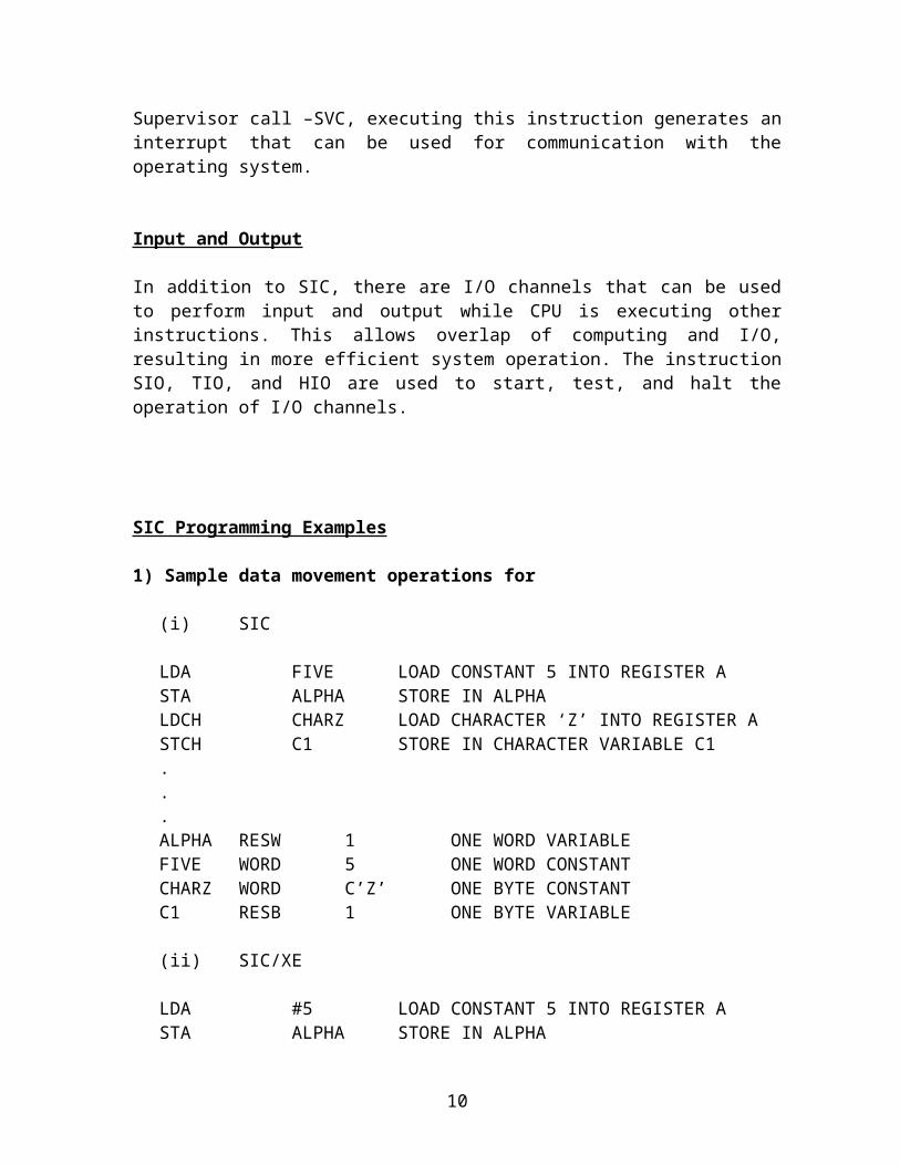
MULR, DIVRSupervisor call –SVC, executing this instruction generates an interrupt that can be used for communication with the operating system.
Input and Output
In addition to SIC, there are I/O channels that can be used to perform input and output while CPU is executing other instructions. This allows overlap of computing and I/O, resulting in more efficient system operation. The instruction SIO, TIO, and HIO are used to start, test, and halt the operation of I/O channels.
SIC Programming Examples
1) Sample data movement operations for
(i) SIC
7

LDA FIVE LOAD CONSTANT 5 INTO REGISTER ASTA ALPHA STORE IN ALPHALDCH CHARZ LOAD CHARACTER ‘Z’ INTO REGISTER ASTCH C1 STORE IN CHARACTER VARIABLE C1...ALPHA RESW 1 ONE WORD VARIABLEFIVE WORD 5 ONE WORD CONSTANTCHARZ WORD C’Z’ ONE BYTE CONSTANTC1 RESB 1 ONE BYTE VARIABLE
(ii) SIC/XE
LDA #5 LOAD CONSTANT 5 INTO REGISTER ASTA ALPHA STORE IN ALPHALDCH #90 LOAD ASCII CODE FOR‘Z’INTO REG ASTCH C1 STORE IN CHARACTER VARIABLE C1...ALPHA RESW 1 ONE WORD VARIABLEC1 RESB 1 ONE BYTE VARIABLE
2) Sample arithmetic operations
(i) SIC
LDAALPHA LOAD ALPHA INTO REGISTER A ADD INCR ADD THE VALUE OF INCR STA BETA STORE IN BETA . . . ONEWORD 1 ONE WORD CONSTANT ALPHA RESW 1 BETA RESW 1 INCR RESW 1
(ii) SIC/XE
LDAINCR LOAD VALUE OF INCR INTO REGISTER S LDAALPHA LOAD ALPHA INTO REGISTER A ADDR S,A ADD THE VALUE OF INCR
8

STA BETA STORE IN BETA . . . ALPHA RESW 1 BETA RESW 1 INCR RESW 1
3) Sample looping and indexing operations
(i) SIC
LDX ZERO INITIALIZE INDEX REGISTER TO 0MOVECH LDCH STR1,X LOAD CHARACTER FROM STR1 INTO REG A STCH STR2,X STORE CHARACTER INTO STR2
TIX SEVEN ADD 1 TO INDEX, COMPARE RESULT TO 7 JLT MOVECH LOOP IF INDEX IS LESS THAN 7 . .
STR1 BYTE C ‘TESTING’ 7 BYTE STRING CONSTANTSTR2 RESB 7 7 BYTE VARIABLEZERO WORD 0SEVEN WORD 7
(ii) SIC/XE
LDT #7 INITIALIZE REGISTER TO 7 LDX #0 INITIALIZE INDEX REGISTER TO 0
MOVECH LDCH STR1,X LOAD CHARACTER FROM STR1 INTO REG A STCH STR2,X STORE CHARACTER INTO STR2
TIX T ADD 1 TO INDEX, COMPARE RESULT TO 7 JLT MOVECH LOOP IF INDEX IS LESS THAN 7 . .
STR1 BYTE C ‘TESTING’ 7 BYTE STRING CONSTANTSTR2 RESB 7 7 BYTE VARIABLE
4) Sample indexing and looping operations
(i) SIC
9
LDA ZERO INITIALIZE INDEX VALUE TO 0 STA INDEXADDLP LDX INDEX LOAD INDEX VALUE INTO REGISTER X
LDA ALPHA,X LOAD WORD FROM ALPHA INTO REGISTER A ADD BETA,X ADD WORD FROM BETA STA GAMMA,X STORE THE RESULT IN A WORD IN GAMMA LDA INDEX ADD 3 TO INDEX VALUE ADD THREE STA INDEX COMP K300 COMPARE NEW INDEX VALUE TO 300 JLT ADDLP LOOP IF INDEX IS LESS THAN 300 . . .
INDEX RESW 1 ONE WORD VARIABLE FOR INDEX VALUE ARRAY VARIABLES – 100 WORDS EACH
ALPHA RESW 100BETA RESW 100GAMMA RESW 100ZERO WORD 0 ONE WORD CONSTANTS300 WORD 300
(i) SIC/XE
LDS #3 INITIALIZE RESIGSTER S TO 3 LDT #300 INITIALIZE RESIGSTER T TO 300 LDX #0 INITIALIZE INDEX RESIGSTER TO 0
ADDLP LDA ALPHA,X LOAD WORD FROM ALPHA INTO REGISTER A ADD BETA,X ADD WORD FROM BETA STA GAMMA,X STORE THE RESULT IN A WORD IN GAMMA ADDR S,X ADD 3 TO INDEX VALUE COMP X,T COMPARE NEW INDEX VALUE TO 300 JLT ADDLP LOOP IF INDEX IS LESS THAN 300 . . .
ARRAY VARIABLES – 100 WORDS EACHALPHA RESW 100BETA RESW 100GAMMA RESW 1005) Sample input and output operations
(i) SIC
10

INLOOP TD INDEV TEST INPUT DEVICEJEQ INLOOP LOOP UNTIL DEVICE IS READYRD INDEV READ ONE BYTE INTO RESGITER ASTCH DATA STORE BYTE THAT WAS READ...
OUTLP TD OUTDEV TEST OUTPUT DEVICEJEQ OUTLP LOOP UNTIL DEVICE IS READYLDCH DATA LOAD DATA BYTE INTO REG AWD OUTDEV WRITE ONE BYTE TO O/P DEVICE...
INDEV BYTE X’F1’ INPUT DEVICE NUMBEROUTDEV BYTE X’05’ OUTPUT DEVICE NUMBERDATA RESB 1 ONE BYTE VARIABLE
6) Sample subroutine call and record input operations
(i) SIC
JSUB READ CALL READ SUBROUTINE...
SUBROUTINE TO READ 100 BYTE RECORDREAD LDX ZERO INITIALIZE INDEX REGISTER TO 0RLOOP TD INDEV TEST INPUT DEVICE
JEQ RLOOP LOOP IF DEVICE IS BUSY RD INDEV READ ONE BYTE INTO REGISTER A STCH RECORD,X STORE DATA BYTE INTO RECORD TIX K100 ADD 1 TO INDEX AND COMPARE TO 100 JLT RLOOP LOOP IF INDEX IS LESS THAN 100
RSUB .
. .INDEV BYTE X’F1’ INPUT DEVICE NUMBERRECORD RESB 100 100 BYTE BUFFER FOR I/P RECORDZERO WORD 0K100 WORD 100
11

(ii) SIC/XE
JSUB READ CALL READ SUBROUTINE...
SUBROUTINE TO READ 100 BYTE RECORDREAD LDX #0 INITIALIZE INDEX REGISTER TO 0
LDT #100 INITIALIZE REGISTER T TO 100
RLOOP TD INDEV TEST INPUT DEVICE JEQ RLOOP LOOP IF DEVICE IS BUSY RD INDEV READ ONE BYTE INTO REGISTER A STCH RECORD,X STORE DATA BYTE INTO RECORD TIXR T ADD 1 TO INDEX AND COMPARE TO 100 JLT RLOOP LOOP IF INDEX IS LESS THAN 100
RSUB .
. .INDEV BYTE X’F1’ INPUT DEVICE NUMBERRECORD RESB 100 100 BYTE BUFFER FOR I/P RECORD
12

TRADITIONAL (CISC) MACHINES
The machine described in this section are classified as Complex Instruction Set Computer (CISC).
VAX Architecture
The VAX family of computers was introduced by Digital Equipment Corporation(DEC) in 1978.The VAX architecture was designed for compatibility with earlier PDP-11 machines. It is even possible for PDP-11 programs and VAX programs to share the same machine in a multi-user environment.
Memory
The VAX memory consists of 8-bit bytes. All addresses used are byte addresses. Two consecutive bytes form a word, four bytes form a longword, eight bytes form a quadword, sixteen bytes form an octaword.
All VAX programs operate in a virtual address space of 232 bytes. This virtual memory allows programs to operate as though they had access to an extremely large memory, regardless of the amount of memory actually present on the system. Routines in the operating system take care of the details of memory management. One half of the VAX virtual address space is call system space, which contains the operating system, and is shared by all programs. The other half of the address space is called process space and is defined separately for each program. A part of the process space contains stacks that are available to the programs. Special registers and machine instructions aid in the use of these stacks.
Registers
There are 16 general purpose registers on the VAX, denoted by R0 through R15. Some of them have special names and uses. All general registers are 32 bits in length.
Register R15 – the program counter, also called PC. It is updated during the instruction execution to point to the next instruction byte to be fetched.
Register R14 – the stack pointer SP, which points to the current top of the stack in the program’s process space, hardware instructions that implicitly use the stack always use SP.
Register R13 – the frame pointer FP. VAX procedure call conventions build a data structure called a stack frame, and place its address in FP.
13

Register R12 – the argument pointer AP. The procedure call convention uses AP to pass a list of arguments associated with the call.
Registers R6 through R11 have no special functions, and are available for general use by the program.
Registers R0 through R5 are likewise available for general use, they are also used by some machine instructions.
In addition to general registers, there is a preprocessor status longword (PSL), which contains state variables and flags associated with a process. There are also a number of control registers that are used to support various operating system functions.
Data Formats
Integers are stored as binary numbers in a byte, word, longword, quadword or octaword. 2’s complement representation is used for negative values. Characters are stored using their 8- bit ASCII codes.
There are four different floating point data formats on the VAX, ranging in length from 4 to 16 bytes. Two of these are compatible with those found on the PDP-11 and are standard on all VAX processors. The other two are available as options.
VAX processors provide a packed decimal data format. In this format each byte represents two decimal digits, with each digit encoded using 4 bits of the byte. The sign is encoded in the last 4 bits.
Numeric format that is used to represent values with one digit per byte. In this format, the sign may appear either in the last byte or as a separate byte preceding the first digit. These two variations are called trailing numeric and leading separate numeric.
VAX also supports data structures, such as these can be implemented on any machine. VAX provide direct hardware support for them.
Instruction Format
VAX machine instructions use a variable length instruction format. Each instruction consists of an operation code followed by up to six operand specifiers, depending on the type of instruction. Each operand specifier designates one of the VAX addressing modes and gives any additional information necessary to locate the operand.
14

Addressing Modes
VAX provides a large number of addressing modes. The operand itself may be in a register or its address may be specified by register. If the operand address is in a register, the contents of the register may be automatically incremented and decremented by the operand length.
There are several base relative addressing modes, with displacement fields of different length, when used with register PC, they become program counter relative modes.
Instruction Set
One of the goals of the VAX designers was to produce an instruction set that is symmetric with respect to data type. Many instruction mnemonics are formed by combining the following elements
1. A prefix that specifies the type of operation2. A suffix that specifies the data type of the operands3. A modifier that gives the number of operands involved.
Ex., ADDW2 is an add operation with two operands, each a word in length.
VAX provides all of the usual types of instructions for computation, data movement, etc., There are also powerful instructions for calling and returning from procedures.
Input and Output
Input and output on the VAX are accomplished by I/O device controllers. Each controller has a set of control/status and data registers, which are signed locations in the physical address space. The portion of the address space into which the device controller registers are mapped is called I/O space.
No special instructions are required to access register in I/O space. I/o device driver issues command to device controller by storing values in the appropriate registers. The association of an address in I/O space with a physical register in a device controller is handled by the memory management routines.
PENTIUM PRO ARCHITECTURE
The Pentium Pro microprocessor, is the latest introduction in the Intel x86 family. The various x86 processors differ in implementation details and operating speed. This section contains an overview of the x86 architecture.
Memory
Memory in x86 are described in two different ways. At physical level, memory consists of 8-bit bytes. Two consecutive bytes form a word, four bytes form a double word.
15

Usually x86 memory are viewed as a collection of segments. An address consists of two parts – a segment number and offset that points to a byte within the segment. Segments are of different sizes, some segments may contain executable instructions and other segments may used to store data.
In some cases segments can be divided into pages. Some of the pages of the segment may be physical memory, while others may be stored on the disk. When x86 instruction is executed, the hardware and operating system make sure that the needed byte of the segment is loaded into physical memory. The segment/offset address specified by the
programmer is automatically translated into a physical byte address by the programmer automatically translated into a physical byte address by the x86 Memory Management Unit (MMU).
Registers
There are eight general-purpose registers, which are named EAX, EBX, ECX, EDX, ESI, EDI EBP and ESP. Each general-purpose register is 32 bits long. First four registers are used for data manipulation and the other four registers are used for data, but are more commonly used to hold addresses.
Special-purpose registers
EIP is 32 bit register contains a pointer to the next instruction to be executed.
FLAGS is a 32 bit register contains different bit flags.
There are six 16-bit segment registers that are used to locate segments in the memory.
DS, ES, FS, and GS are used to indicate the addresses of data segments.
Data Formats
Integer are normally stored as 8,16 or 32 bit binary numbers. Both signed and unsigned integers are supported. 2’s complement is used for negative values. Integers can also be stored in binary coded decimal. In the unpacked BCD format, each byte represents one decimal digit. The value of this digit is encoded in the lower order 4 bits of the byte, the high order bits are normally zero. In packed BCD, each byte represents two decimal digits, with each digit encoded using 4 bits of the byte.
There are three different floating point data formats.
1. Single precision -32 bits long, stores 24 significant bits of the floating point value and allow for a 7 bit exponent.
16

2. Double precision -64 bits long, stores 53 significant bits of the floating point value and allow for a 10 bit exponent.
3. Extended precision -80 bits long, stores 64 significant bits of the floating point value and allow for a 15 bit exponent.
Characters are stored one per byte, using 8-bit ASCII codes. Strings consists of bits, bytes, words or doublewords.
Instruction Formats
All the x86 machine instructions use variations of the same basic format. This format begins with the optional prefixes containing flags that modify the operation of the instruction. For example, some prefixes specify a repetition count for an instruction. Others specify a segment register that is to be used for addressing an operand. Following the prefixes is an opcode, each specifying a different variant of the operation. Following the opcode are a number of bytes of bytes that specify the operands and addressing modes to be used. The opcode is the only element that is always present in every instruction.
Addressing Modes
The x86 architecture provides a large number of addressing modes. An operand value may be specified as part of the instruction itself or register.
Operand stored in memory are often specifies using variations of the general target address calculation.
TA= (base register) + (index register) * (scale factor) + displacement
Any general-purpose register may be used as a base register, except ESP can be used as an index register. The scale factor may have the value 1, 2, 4 or 8 and the displacement are encoded as parts of the operand specifiers in the instruction. The address of the operand in memory may be specified as an absolute location or as relative to EIP register.
Instruction Set
The x86 architecture has a large and complex instruction set containing more than 400 different machine instructions. An instruction may have 0,1,2 or 3 operands. There are register-register instructions, register-memory instructions and a few memory-to-memory instructions. In some operands are specified as immediate values in the instruction.
Data movement and integer arithmetic instructions use operands of 1, 2, or 4 bytes long. String manipulation instructions use repetition prefixes, which directly deals with
17

variable-length strings of bytes, words or doublewords. It also includes special purpose instructions like entering and leaving procedures and checking subscript values against the bounds of an array.
Input and Output
Input is performed by instructions that transfer 1 byte, word or doubleword at a time from an I/O port into register EAX.
Output is performed by instructions that transfer 1 byte, word or doubleword at a time from an EAX to an I/O port.
RISC MACHINES
RISC (Reduced Instruction Set Computers) was intended to simplify the design of processors. The simplified design can result in faster and less expensive processor development, greater reliability and faster instruction execution times.
RISC system is characterized by a standard, fixed instruction length and single-cycle execution of most instructions. Memory access is usually done by load and store instructions. All instructions except load and store use register-register operations. The number of machine instructions, instruction formats and addressing modes is relatively small.
UltraSPARC Architecture
18

The UltraSPARC processor, is the latest member of the SPARC family. The architecture is intended to be suitable for a wide range of implementations, form microcomputers to supercomputers.
Memory
Memory consists of 8-bit bytes, all addresses used are byte addresses. 2 consecutive bytes – halfword, stored in memory beginning at byte addresses that are multiples of 2.4 bytes - word, stored in memory beginning at byte addresses that are multiples of 4.8 bytes - doubleword, stored in memory beginning at byte addresses that are multiples of 8.
UltraSPARC programs can be written using a virtual address space of 264 bytes. This address space is divided into pages, multiple page sizes are supported. Some of the pages used by a program may be in physical memory, while others may be stored on disk. When an instruction is executed, the h/w and operating system make sure that the needed page is loaded in physical memory. The virtual address specified by the instruction is automatically translated into physical address by the UltraSPARC Memory Management Unit (MMU).
Registers
The SPARC architecture includes a large register file usually contains 100 general-purpose registers. Normally they are 32 bits long, later they are expanded to 63 bits. Register r0 through r31 are global and can be accessed by any procedure. The other 24 registers available to a procedure can be visualized as a window through which part of the register file can be seen. These windows overlap, so some registers in the register file are shared between procedures. For ex., r8 through r15 of a calling procedure are physically the same registers as r24 through r31 of the called procedure.
If a set of concurrently running procedures needs more windows than a physically available, a “window Overflow” interrupt occurs. The operating system saves the contents of some registers in the file to provide the additional windows that are needed.
Floating point computations are performed using a special floating-point unit (FPU). This unit contains a file of 64 double precision floating-point registers, and several other control and status registers. Besides these, there are program counter, condition code registers, and a number of other control registers.
Data Formats
19

Integers are stored as 8, 16, 32 or 64 bit binary numbers. Both signed and unsigned integers are supported. 2’s complement is used for negative values. The most significant part of a numeric value is stored at the lowest-numbered address. (“big-endian” –big end of the value comes first in memory.) UltraSPARC supports both big-endian and little-endian byte ordering.
There are three different floating point data formats.
1. Single precision -32 bits long, stores 23 significant bits of the floating point value and allow for a 8 bit exponent.
2. Double precision -64 bits long, stores 52 significant bits of the floating point value and allow for a 11 bit exponent.
3. Quad-precision stores 63 significant bits of the floating point value and allow for a 15 bit exponent.
Characters are stored one per byte, using 8-bit ASCII codes.
Instruction Formats
There are three basic instruction formats in the SPARCarchitecture. All of these formats are 32 bits long, the first 2 bits of the instruction word identify which format is being used. Format1 is used for the call instruction. Format2 is used for branch instructions. The remaining instructions use format3, which provides for register loads and stores, and three-operand arithmetic operations.
The fixed instruction length in the SPARC architecture is typical of RISC systems, and is intended to speed the process of instruction fetching and decoding.
Addressing Modes
In this architecture, the operand value may be specified as part of the instruction itself or it may be in a register. Operands in memory are addressed using one of the following three modes
20

Mode Target Address Calculation
PC- relative TA= (PC) + displacement (30 bits, signed)
Register indirect with displacement TA= (register)+ displacement
(13 bits, signed) Register indirect indexed TA=(register-1) + (register-2)
Instruction Set
This architecture has fewer than 100 machine instructions. The only instructions that access memory are loads and stores. All other instructions are register-register operations.
Instruction execution on a SPARC system is pipelined, while one instruction is executed, the next one is being fetched from memory and decoded. This technique speeds instruction execution. An branch instruction cause the process to “stall”. The instruction following branch have to be discarded without being executed.
To make the pipeline work more efficiently, SPARC branch instructions are delayed branches. This means the instruction following the branch instruction is executed before the branch is taken.
They also include special purpose instructions to provide support for operating system and optimizing compilers. Communication in a multi-processor system is facilitated by special “atomic” instructions. Conditional move instructions allow a complier to eliminate many branch instructions in order to optimize program execution.
Input and Output
In this architecture, communication with I/O devices is accomplished through memory. A range of memory locations is logically replaced by device registers. Each I/O device has a unique address. When a load or store instruction refers to this device register area of memory, the corresponding device is activated.
21

PowerPC Architecture
IBM introduced the POWER(Performance Optimization With Enhanced RISC.)PowerPC is a RISC architecture. It has much in common with other RISC systems such as SPARC.
Memory
Memory consists of 8-bit bytes, all addresses used are byte addresses. 2 consecutive bytes – halfword, 4 bytes form a word.
8 bytes - doubleword
16 bytes - quadword
PowerPC programs can be written using a virtual address space of 264 bytes. This address space is divided into fixed-length segments, which are 256 mb long. Each segment is divided into pages, which is 4096 bytes long. Some of the pages used by a program may be in physical memory, while others may be stored on disk. When an instruction is executed, the h/w and operating system make sure that the needed page is loaded in physical memory. The virtual address specified by the instruction is automatically translated into physical address.
Registers
There are 32 general-purpose registers, GPR0 through GPR31. Each register is 64 bits long. PowerPC can be implemented in a 32-bit subset, which used 32-bit registers. General purpose registers can be used to store and manipulate integer data and addresses.
Floating-point computations are performed using a special floating-point unit (FPU). This unit contains 64-bit floating point registers, and a status and control register.
A 32-bit condition register reflects the result of certain operations like testing and branching. This register is divided into eight 4-bit subfields, named CR0 through CR7.
22

The PowerPC includes a Link Register (LR) and a Count Register (CR), used by some branching instructions. There is also Machine Status Register (MSR) and variety of other control and status registers, some of which are implementation dependent.
Data Formats
Integers are stored as 8, 16, 32 or 64 bit binary numbers. Both signed and unsigned integers are supported. 2’s complement is used for negative values. The most significant part of a numeric value is stored at the lowest-numbered address. (“big-endian” –big end of the value comes first in memory.) It is possible to select little-endian byte ordering by setting a bit in a control register.
There are two different floating-point data formats.
1. Single precision -32 bits long, stores 23 significant bits of the floating-point value and allow for a 8 bit exponent.
2. Double precision -64 bits long, stores 52 significant bits of the floating-point value and allow for a 11 bit exponent.
Characters are stored one per byte, using 8-bit ASCII codes.
Instruction Formats
There are seven basic instruction formats in the PowerPC architecture, some of which are subforms. All of these formats are 32 bits long. Instructions must be aligned beginning at a word boundary. The first 6 bits of the instruction word specify the opcode, some instruction formats have an additional “extended opcode” field.
The fixed instruction length in the PowerPC architecture is typical of RISC systems. The variety and complexity of instruction formats is greater than that found on most RISC systems.
Addressing Modes
An operand value may be specified as part of the instruction itself or it may be in a register. The only instructions that address memory are load and store operations, and branch instructions.
Load and store operations use one of the following 3 addressing modes:
23

Mode Target Address Calculation
Register indirect TA= (register)
Register indirect with index TA= (register-1)+(register-2)
Register indirectwith immediate index TA=(register) + displacement
(16 bits, signed)
Branch instructions use one of the following 3 addressing modes:
Mode Target Address Calculation
Absolute TA= actual address
Relative TA= current instruction address+ displacement(25bits, signed)
Link register TA= (LR)
Count Register TA= (CR)
Instruction Set
They have approximately 200 machine instructions. Some of the instructions are more complex than RISC systems. For example, load and store instructions automatically update the index register to contain the just computed target address.
Floating-point “multiply and add” instructions take three input operands and perform multiplication and addition in one instruction. Such instructions reflect the powerful approach of the PowerPC, so fewer instructions are required to perform a task.
Instruction execution on a PowerPC system is pipelined as discussed in SPARC.
Input and Output
24

It provides 2 different methods for performing I/O operations. In one approach, segments in the virtual address space are mapped onto an external address space. Segments that are mapped in this way are called direct-storage segments.
A reference to an address that is not in a direct-store segment represents a normal virtual memory access. In this case I/O is performed using the regular virtual memory management hardware and software.
Cray T3E Architecture
The T3E series of supercomputers was announced by Cray Research, Inc.,. The T3E is a massively parallel processing (MPP) system. It contains a large number of processing elements (PE), arranged in a 3d network. This network provides a path for transferring data between processors. It also implements control functions that are used to synchronize the operation of the PEs used by a program. The interconnect network is circular in each dimension. Thus PEs at “opposite” ends of the 3d array are adjacent with the respect to the network. This is illustrates by the dashed lines.
InterconnectNetwork
Processing Element Node
Memory
T3E has its own local memory with a capacity of from 64mb to 3gb. The local memory within each PE is part of a physically distributed, logically shared memory system. System memory is logically shared because the microprocessor in one PE can access memory of another PE without involving the microprocessor in that PE.
25

The memory within each processing element consists of 8-bit bytes, all addresses used are byte addresses.
2 consecutive bytes – word
4 bytes - longword
8 bytes - quadword
Many alpha instructions may execute more efficiently if operands are aligned at a starting address that is multiple of their length. The alpha architecture supports 64-bit virtual addresses.
Registers
It includes 32 general-purpose registers, R0 through R31, R31 always contains the value 0. Each register is 64 bits long. They can be used to store and manipulate integer data and addresses.
There are 32 floating-point registers, F0 through F31, F31 always contains the value 0. It is 64 bits long. In addition, there is 64-bit program counter PC and other status and control registers.
Data Formats
The alpha architecture provides for the storage of integers, floating-point values and characters. Integers are stored as longwords or quadwords. 2’s complement is used for negative values. When interpreted as an integer, the bits of a longword or quadword steadily increase significance beginning with bit 0.
There are 2 different types of floating-point data formats in the alpha architecture. One group of 3 formats is included for compatibility with the VAX architecture. The other group consists of 4 IEEE standard formats which is compatible with those used on most modern systems.
Characters are stored one per byte, using 8-bit ASCII codes.
Instruction Formats
26

There are 5 basic instruction formats in the alpha architecture, some of which are subforms. All of these formats are 32 bits long. The first 6 bits of the instruction word always specify the opcode, some instruction formats have an additional “function” field.
Addressing Modes
The operand value may be specified as part of the instruction itself or it may be in a register. The only instructions that address memory are load and store operations, and branch instructions.
Operands in memory are addressed using one of the following 2 modes:
Mode Target Address Calculation
PC relative TA= (PC)+displacement(23bits, signed)
Register indirect with displacement TA=(register) + displacement
(16 bits, signed)
Instruction Formats
It has nearly 130 machine instructions, reflecting its RISC orientation. The instruction set is designed so that an implementation of the architecture can be fast as possible. This means the memory access interface does not need to include shift-and –mask operations.
Input and Output
The T3E system performs I/O through multiple ports into one or more I/O channels. These channels are integrated into the network that interconnects the processing nodes. A system may be configured with up to one I/O channel for every 8 PEs. All the channels are accessible and controllable from all PEs.
27

28