M090 Modbus TCP / DALI converter - Domat...
21
domat M090 04/2016 Subject to technical changes. 1 M090 Modbus TCP / DALI converter Summary M090 is a serial converter which acts as a Modbus TCP server (accepts Modbus TCP commands) and controls a DALI (Digital Addressable Light Interface) bus with up to 64 DALI devices. M090 acts as a single master of the DALI bus. It also incorporates a web interface for manual entering of DALI commands inclusive bus configuration and diagnostic commands. Applications integration of DALI light controllers to a Modbus TCP compatible SCADA or PLC configuring and controlling of a DALI bus over a comfortable web interface, even on a remote basis Function The M090 converter acts as a single master of the DALI bus. It cannot be used with another DALI master, like switches, light sensors etc. on the same bus. The Modbus and web commands are translated into DALI protocol telegrams and sent to the DALI devices. The responses from the light controllers are translated back to Modbus registers and available at the corresponding addresses, see tables below. The DALI bus supports up to 64 light controller addresses, up to 16 scenes, and up to 16 groups. Wire length and diameter must always be respected! For the complete overview of the DALI bus specification, see e.g. http://www.dali- ag.org/c/manual_gb.pdf . The DALI bus uses 22.5 V operation voltage. If the bus is loaded, the warm dissipation have to be guaranteed. The warm is product of frequent communication with high number of converters. Please do not exceed maximal permitted working temperature 55 °C, otherwise the proper function is not guaranteed and the converter could be damaged! The bus devices are connected over a 2-pole connector, regardless of polarity. The Ethernet is connected over RJ45 connector with PoE (Power over Ethernet).
Transcript of M090 Modbus TCP / DALI converter - Domat...

domat M090 04/2016 Subject to technical changes. 1
M090 Modbus TCP / DALI converter
Summary M090 is a serial converter which acts as a Modbus TCP server (accepts Modbus TCP commands) and controls a DALI (Digital Addressable Light Interface) bus with up to 64 DALI devices. M090 acts as a single master of the DALI bus. It also incorporates a web interface for manual entering of DALI commands inclusive bus configuration and diagnostic commands.
Applications integration of DALI light controllers to a Modbus TCP compatible SCADA or PLC
configuring and controlling of a DALI bus over a comfortable web
interface, even on a remote basis
Function The M090 converter acts as a single master of the DALI bus. It cannot be used with another DALI master, like switches, light sensors etc. on the same bus. The Modbus and web commands are translated into DALI protocol telegrams and sent to the DALI devices. The responses from the light controllers are translated back to Modbus registers and available at the corresponding addresses, see tables below. The DALI bus supports up to 64 light controller addresses, up to 16 scenes, and up to 16 groups. Wire length and diameter must always be respected! For the complete overview of the DALI bus specification, see e.g. http://www.dali-ag.org/c/manual_gb.pdf . The DALI bus uses 22.5 V operation voltage. If the bus is loaded, the warm dissipation have to be guaranteed. The warm is product of frequent communication with high number of converters. Please do not exceed maximal permitted working temperature 55 °C, otherwise the proper function is not guaranteed and the converter could be damaged! The bus devices are connected over a 2-pole connector, regardless of polarity. The Ethernet is connected over RJ45 connector with PoE (Power over Ethernet).
2 04/2016 Subject to technical changes. domat M090
______________________________________________________________________
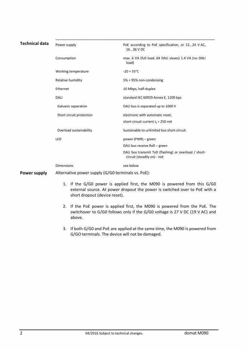
Technical data Power supply PoE according to PoE specification, or 12...24 V AC, 16...36 V DC
Consumption max. 6 VA (full load, 64 DALI slaves) 1.4 VA (no DALI load)
Working temperature -20 ÷ 55°C
Relative humidity 5% ÷ 95% non-condensing
Ethernet 10 Mbps, half-duplex
DALI standard IEC 60929 Annex E, 1200 bps
Galvanic separation DALI bus is separated up to 1000 V
Short circuit protection electronic with automatic reset,
short-circuit current Ik = 250 mA
Overload sustainability Sustainable to unlimited bus short-circuit
LED power (PWR) – green
DALI bus receive RxD – green
DALI bus transmit TxD (flashing) or overload / short-circuit (steadily on) - red
Dimensions see below
Power supply Alternative power supply (G/G0 terminals vs. PoE):
1. If the G/G0 power is applied first, the M090 is powered from this G/G0 external source. At power dropout the power is switched over to PoE with a short dropout (device reset).
2. If the PoE power is applied first, the M090 is powered from the PoE. The
switchover to G/G0 follows only if the G/G0 voltage is 27 V DC (19 V AC) and above.
3. If both G/G0 and PoE are applied at the same time, the M090 is powered from
G/GO terminals. The device will not be damaged.
domat M090 04/2016 Subject to technical changes. 3
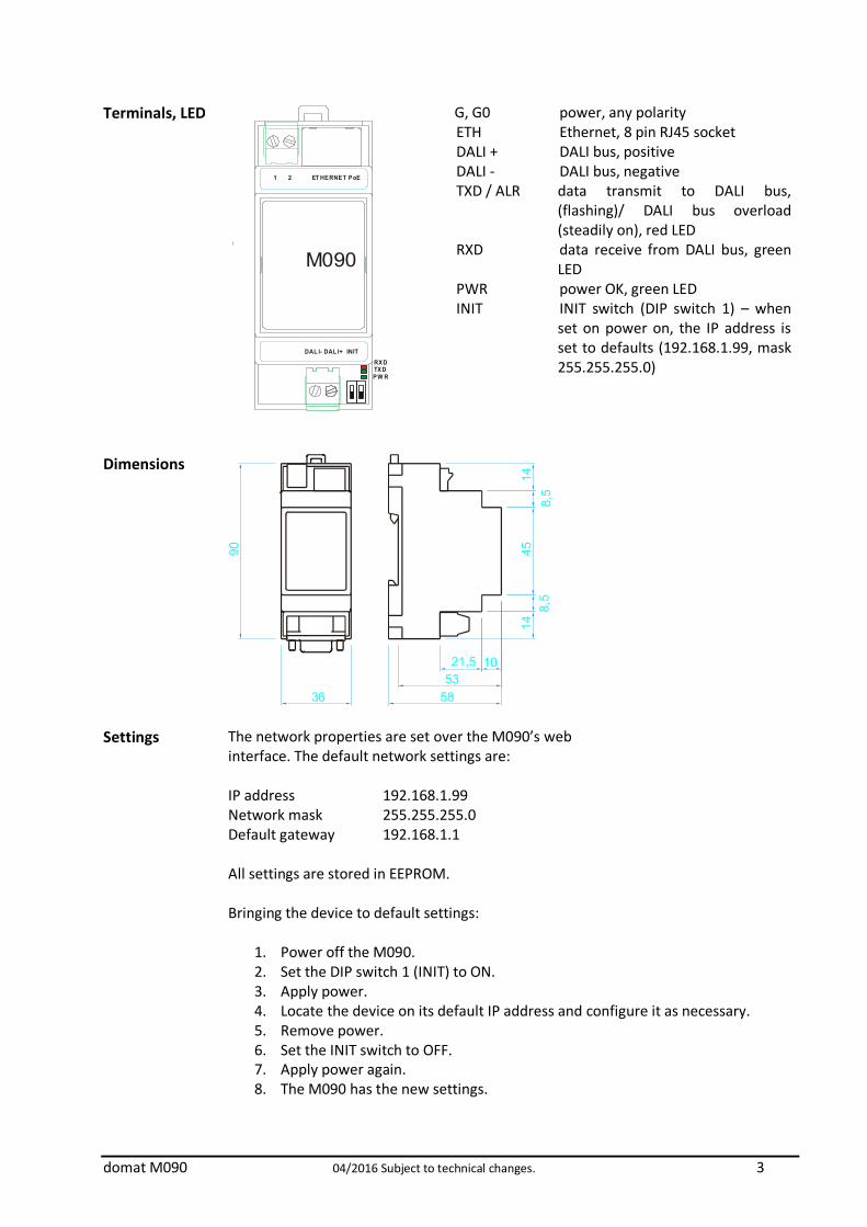
Terminals, LED
DAL I- DAL I+ INIT
M090
RXDTXDPW R
1 2 ET HERNET PoE
G, G0 power, any polarity ETH Ethernet, 8 pin RJ45 socket DALI + DALI bus, positive DALI - DALI bus, negative TXD / ALR data transmit to DALI bus,
(flashing)/ DALI bus overload (steadily on), red LED
RXD data receive from DALI bus, green LED
PWR power OK, green LED INIT INIT switch (DIP switch 1) – when
set on power on, the IP address is set to defaults (192.168.1.99, mask 255.255.255.0)
Dimensions
5853
1021,5
458,
58,
514
14
90
36
Settings The network properties are set over the M090’s web interface. The default network settings are: IP address 192.168.1.99 Network mask 255.255.255.0 Default gateway 192.168.1.1 All settings are stored in EEPROM. Bringing the device to default settings:
1. Power off the M090. 2. Set the DIP switch 1 (INIT) to ON. 3. Apply power. 4. Locate the device on its default IP address and configure it as necessary. 5. Remove power. 6. Set the INIT switch to OFF. 7. Apply power again. 8. The M090 has the new settings.
4 04/2016 Subject to technical changes. domat M090
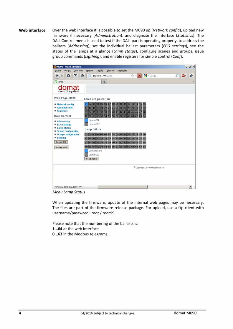
Web interface
Over the web interface it is possible to set the M090 up (Network config), upload new firmware if necessary (Administration), and diagnose the interface (Statistics). The DALI Control menu is used to test if the DALI part is operating properly, to address the ballasts (Addressing), set the individual ballast parameters (ECG settings), see the states of the lamps at a glance (Lamp status), configure scenes and groups, issue group commands (Ligthing), and enable registers for simple control (Conf).
Menu Lamp Status When updating the firmware, update of the internal web pages may be necessary. The files are part of the firmware release package. For upload, use a ftp client with username/password: root / root99. Please note that the numbering of the ballasts is: 1...64 at the web interface 0...63 in the Modbus telegrams.

domat M090 04/2016 Subject to technical changes. 5
Menu ECG Settings
Conf – Simple control enable menu The web interface is useful when commissioning the system: the DALI bus may be checked separately from the PLC program. As soon as the groups are configured and it is possible to control the DALI ballasts over the web interface, it is time to commission
6 04/2016 Subject to technical changes. domat M090
the PLC part. In the SoftPLC, there is a special driver for M090 so that the integration is easy – it is not necessary to map the Modbus registers via a generic Modbus driver, there are dedicated variables to control central commands, groups, scenes, as well as individual ballasts.
Installation Please ensure that, when installed onto a DIN rail, there is at least a 15 mm gap for air circulation at both vertical device sides, which is necessary for proper cooling of the device.
Related products
IPLC510 process station MiniPLC – Linux IPLC301 process station MiniPLC IPLC201 process station MiniPLC IPCT.1 process station with touch screen display IPCB.1 process station without display RC-Vision SCADA software
Modbus TCP communication
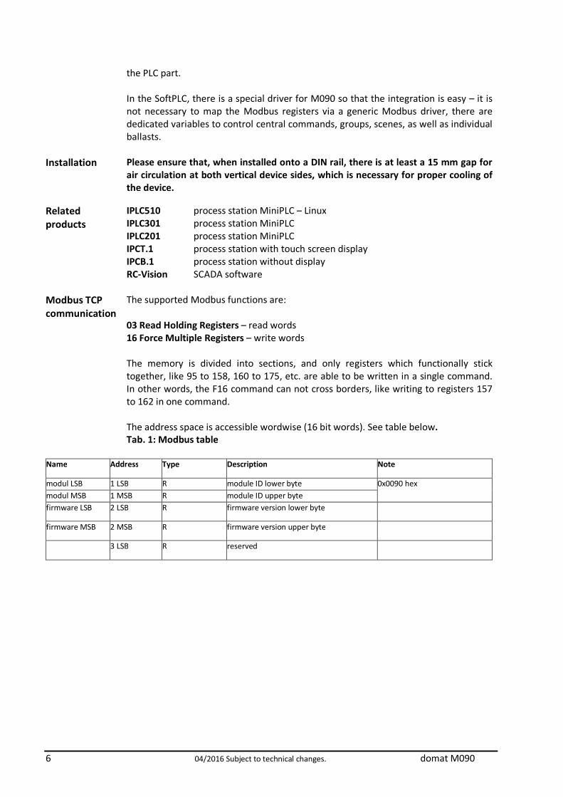
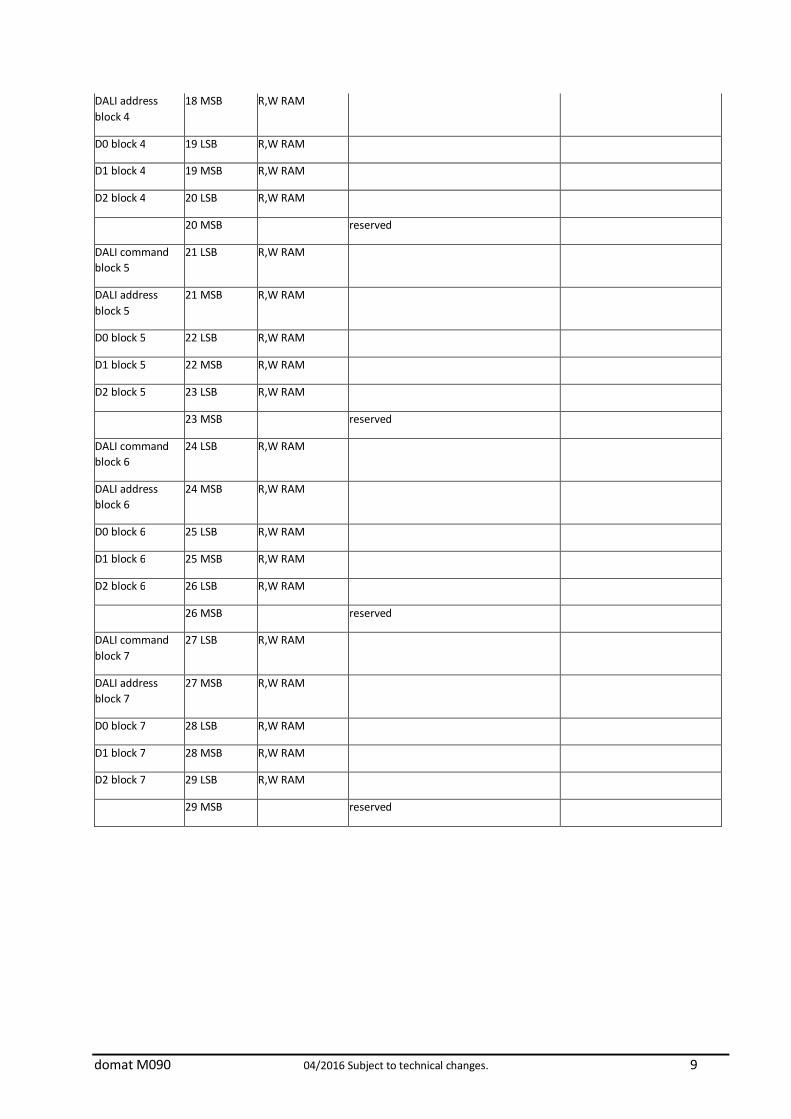
The supported Modbus functions are: 03 Read Holding Registers – read words 16 Force Multiple Registers – write words The memory is divided into sections, and only registers which functionally stick together, like 95 to 158, 160 to 175, etc. are able to be written in a single command. In other words, the F16 command can not cross borders, like writing to registers 157 to 162 in one command. The address space is accessible wordwise (16 bit words). See table below. Tab. 1: Modbus table
Name Address Type Description Note
modul LSB 1 LSB R module ID lower byte 0x0090 hex modul MSB 1 MSB R module ID upper byte firmware LSB 2 LSB R firmware version lower byte
firmware MSB 2 MSB R firmware version upper byte
3 LSB R reserved

domat M090 04/2016 Subject to technical changes. 7
status MSB 3 MSB R module status upper byte
bit 0 - 0 normal mode
- 1 init mode
bit 1 - 0
bit 2 - 0
bit 3 - 0
bit 4 - 0
bit 5 - 1
bit 6 - 0
bit 7 - 1
reserved 4 LSB R RAM
reserved 4 MSB R RAM
command mask 5 LSB R,W RAM bit 0 = block 0
bit 1 = block 1
bit 2 = block 2
bit 3 = block 3
bit 4 = block 4
bit 5 = block 5
bit 6 = block 6
bit 7 = block 7
By setting the bit, executing of the corresponding block is enabled. The module executes the enabled blocks one after another from bit 7 to bit 0
command executed
5 MSB R RAM The set bit indicates the executed block, bit 0 = block 0 etc.
DALI command block 0
6 LSB R,W RAM DALI command for block 0 according to the tables
DALI address block 0
6 MSB R,W RAM DALI address for block 0
D0 block 0 7 LSB R,W RAM if the request is performed by a single DALI command which contains answer, the answer is in this block
additional data 0 for block 0 -> tables

8 04/2016 Subject to technical changes. domat M090
D1 block 0 7 MSB R,W RAM If the request is performed by a
single DALI command, then:
0x00 – no reply returned
0x55 – valid DALI reply returned, and stored in register 7LSB
0x02 – bus error, bus permanently short-circuited
0x03 – DALI reply returned but damaged (unrecognized)
Note 1
additional data 1 for block 0 -> tables
D2 block 0 8 LSB R,W RAM additional data 2 for block 0 -> tables
8 MSB reserved
DALI command block 1
9 LSB R,W RAM
DALI address block 1
9 MSB R,W RAM
D0 block 1 10 LSB R,W RAM
D1 block 1 10 MSB R,W RAM
D2 block 1 11 LSB R,W RAM
11 MSB reserved
DALI command block 2
12 LSB R,W RAM
DALI address block 2
12 MSB R,W RAM
D0 block 2 13 LSB R,W RAM
D1 block 2 13 MSB R,W RAM
D2 block 2 14 LSB R,W RAM
14 MSB reserved
DALI command block 3
15 LSB R,W RAM
DALI address block 3
15 MSB R,W RAM
D0 block 3 16 LSB R,W RAM
D1 block 3 16 MSB R,W RAM
D2 block 3 17 LSB R,W RAM
17 MSB
DALI command block 4
18 LSB R,W RAM
domat M090 04/2016 Subject to technical changes. 9
DALI address block 4
18 MSB R,W RAM
D0 block 4 19 LSB R,W RAM
D1 block 4 19 MSB R,W RAM
D2 block 4 20 LSB R,W RAM
20 MSB reserved
DALI command block 5
21 LSB R,W RAM
DALI address block 5
21 MSB R,W RAM
D0 block 5 22 LSB R,W RAM
D1 block 5 22 MSB R,W RAM
D2 block 5 23 LSB R,W RAM
23 MSB reserved
DALI command block 6
24 LSB R,W RAM
DALI address block 6
24 MSB R,W RAM
D0 block 6 25 LSB R,W RAM
D1 block 6 25 MSB R,W RAM
D2 block 6 26 LSB R,W RAM
26 MSB reserved
DALI command block 7
27 LSB R,W RAM
DALI address block 7
27 MSB R,W RAM
D0 block 7 28 LSB R,W RAM
D1 block 7 28 MSB R,W RAM
D2 block 7 29 LSB R,W RAM
29 MSB reserved

10 04/2016 Subject to technical changes. domat M090
enable functions for simple control
30 LSB, MSB R,W EEPROM
default 0x7F hex
(all enabled)
bit0 – enable round for error states and status readout
bit1 – enable analogue intensity control - ballasts
bit2 – enable analogue intensity control - groups
bit3 – enable analogue intensity control - broadcast
bit4 – enable bit (on/off) control - ballasts
bit5 – enable bit (on/off) control – groups
bit6 – enable bit (on/off) control broadcast (central on/off)
status of ballast 1 31 LSB R RAM bit 0 - Status of ballast; "0" = OK
bit 1 -Lamp failure; "0" = OK
bit 2 - Lamp arc power on; "0" = OFF
bit 3 - Query: Limit Error; "0" = Last requested arc power level is between MIN..MAX LEVEL or OFF bit 4 - Fade ready; "0" = fade is ready; "1" = fade is running bit 5 - Query: "RESET STATE"? "0" = "No"
bit 6 - Query: Missing short address? "0" = "No"
bit 7 - Query: "POWER FAILURE"? "0" = "No"; "RESET" or an arc power control command has been received since last power-on. The "STATUS INFORMATION" shall be available in the RAM of the ballast and shall be updated regularly by the ballast according to the actual situation.
The responses are same as command 144 responses from standard DALI table.
See DALI standard.
status of ballast 1 31 MSB R RAM bit 0:
- 0 - ballast communication is OK
- 1 - ballast is not communicate
status of ballast 2 32 LSB R RAM See status of ballast 1.
status of ballast 2 32 MSB R RAM See status of ballast 1.
… ... ... … …

domat M090 04/2016 Subject to technical changes. 11
status of ballast 64
94 LSB R RAM See status of ballast 1.
status of ballast 64
94 MSB R RAM See status of ballast 1.
ballast 1 intensity 95 LSB,
MSB
R,W RAM Analogue intensity value for ballast 1 (0-255).
It is written during writing.
Function must be enabled in register 30
bit 1.
Note 2
ballast 2 intensity 96 LSB,
MSB
R,W RAM
ballast 3 intensity 97 LSB,
MSB
R,W RAM
... ... ....
ballast 64 intensity
158 LSB,
MSB
R,W RAM
error and status readout round trip
159 LSB,
MSB
R,W EEPROM default 60 sec
Value is in sec. (0 – 65535). If the value is 0, status and error is not read.
group intensity 1 160 LSB,MSB R,W RAM Analogue value of group 1 intensity (0-255). It is written during writing.
Function must be enabled in register 30
bit 2.
group intensity 2 161 LSB,MSB R,W RAM
group intensity 3 162 LSB,MSB R,W RAM
... ... ...
group intensity 16 175 LSB,MSB R,W RAM
analogue broadcast value
176 LSB,MSB R,W RAM Analogue value of all ballasts intensity (0-255) – central command
bit control of ballasts 1-16
177 LSB,MSB R,W RAM – switch off
– switch on
It is written during writing.
Function must be enabled in register 30
bit 4.
bit 0 –ballast 1
bit 1 – ballast 2
bit 2 – ballast 3
bit control of ballasts 17-32
178 LSB,MSB R,W RAM
bit control of ballasts 33-49
179 LSB,MSB R,W RAM
12 04/2016 Subject to technical changes. domat M090
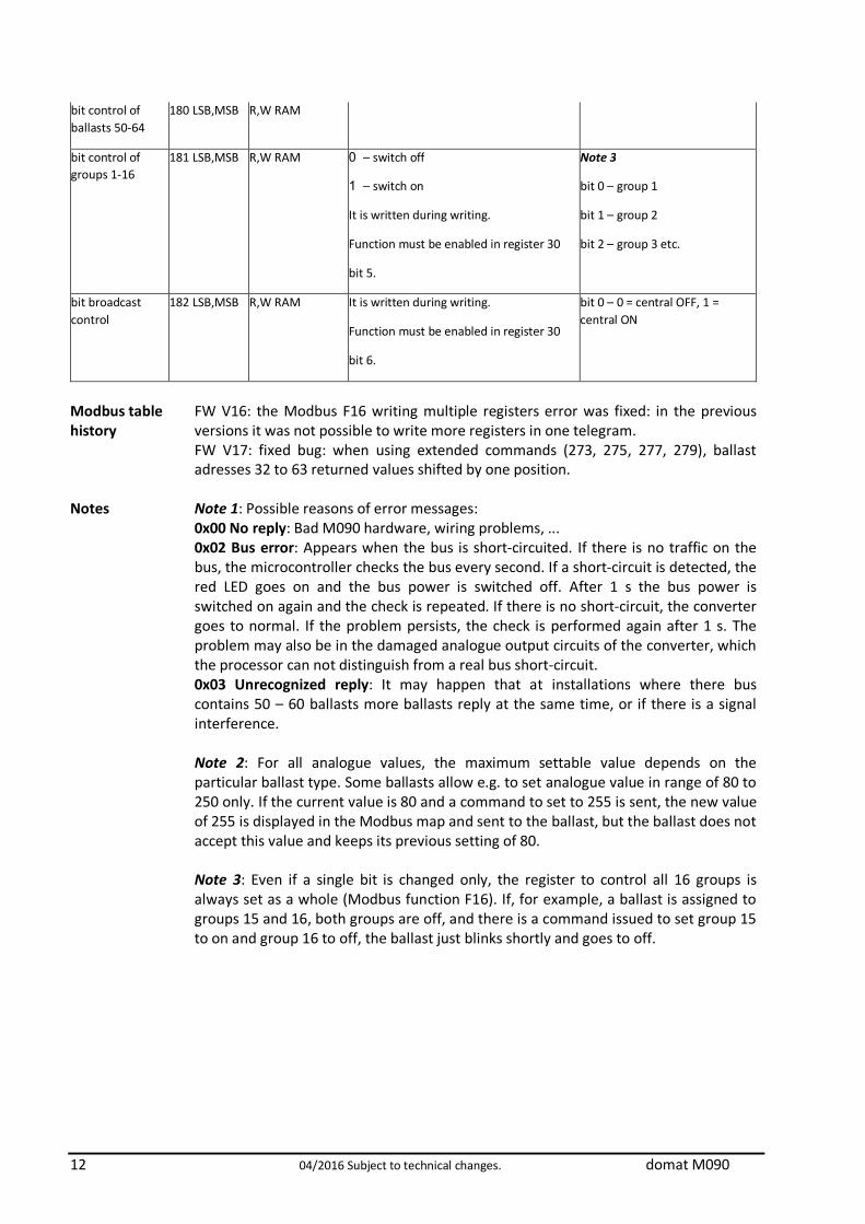
bit control of ballasts 50-64
180 LSB,MSB R,W RAM
bit control of groups 1-16
181 LSB,MSB R,W RAM 0 – switch off
1 – switch on
It is written during writing.
Function must be enabled in register 30
bit 5.
Note 3
bit 0 – group 1
bit 1 – group 2
bit 2 – group 3 etc.
bit broadcast control
182 LSB,MSB R,W RAM It is written during writing.
Function must be enabled in register 30
bit 6.
bit 0 – 0 = central OFF, 1 = central ON
Modbus table history
FW V16: the Modbus F16 writing multiple registers error was fixed: in the previous versions it was not possible to write more registers in one telegram. FW V17: fixed bug: when using extended commands (273, 275, 277, 279), ballast adresses 32 to 63 returned values shifted by one position.
Notes Note 1: Possible reasons of error messages: 0x00 No reply: Bad M090 hardware, wiring problems, ... 0x02 Bus error: Appears when the bus is short-circuited. If there is no traffic on the bus, the microcontroller checks the bus every second. If a short-circuit is detected, the red LED goes on and the bus power is switched off. After 1 s the bus power is switched on again and the check is repeated. If there is no short-circuit, the converter goes to normal. If the problem persists, the check is performed again after 1 s. The problem may also be in the damaged analogue output circuits of the converter, which the processor can not distinguish from a real bus short-circuit. 0x03 Unrecognized reply: It may happen that at installations where there bus contains 50 – 60 ballasts more ballasts reply at the same time, or if there is a signal interference. Note 2: For all analogue values, the maximum settable value depends on the particular ballast type. Some ballasts allow e.g. to set analogue value in range of 80 to 250 only. If the current value is 80 and a command to set to 255 is sent, the new value of 255 is displayed in the Modbus map and sent to the ballast, but the ballast does not accept this value and keeps its previous setting of 80. Note 3: Even if a single bit is changed only, the register to control all 16 groups is always set as a whole (Modbus function F16). If, for example, a ballast is assigned to groups 15 and 16, both groups are off, and there is a command issued to set group 15 to on and group 16 to off, the ballast just blinks shortly and goes to off.
domat M090 04/2016 Subject to technical changes. 13
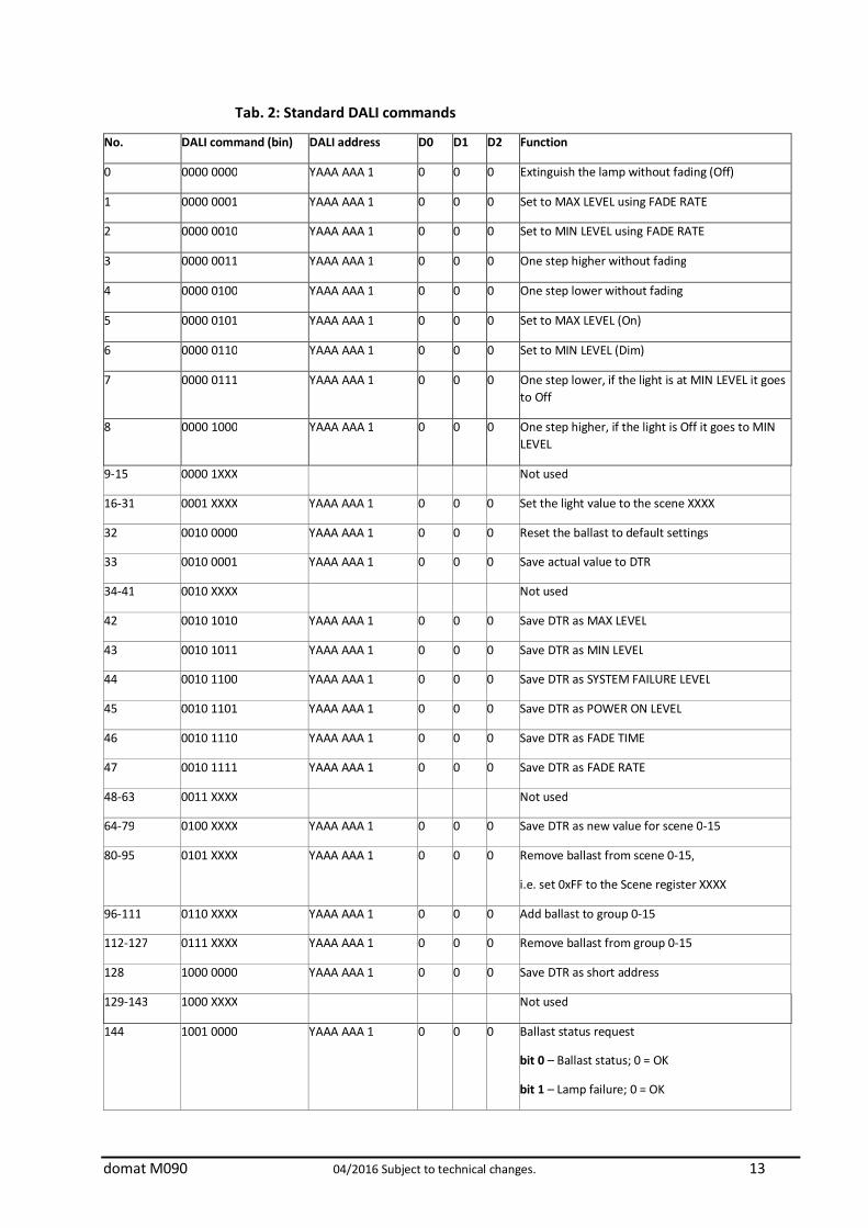
Tab. 2: Standard DALI commands
No. DALI command (bin) DALI address D0 D1 D2 Function
0 0000 0000 YAAA AAA 1 0 0 0 Extinguish the lamp without fading (Off)
1 0000 0001 YAAA AAA 1 0 0 0 Set to MAX LEVEL using FADE RATE
2 0000 0010 YAAA AAA 1 0 0 0 Set to MIN LEVEL using FADE RATE
3 0000 0011 YAAA AAA 1 0 0 0 One step higher without fading
4 0000 0100 YAAA AAA 1 0 0 0 One step lower without fading
5 0000 0101 YAAA AAA 1 0 0 0 Set to MAX LEVEL (On)
6 0000 0110 YAAA AAA 1 0 0 0 Set to MIN LEVEL (Dim)
7 0000 0111 YAAA AAA 1 0 0 0 One step lower, if the light is at MIN LEVEL it goes to Off
8 0000 1000 YAAA AAA 1 0 0 0 One step higher, if the light is Off it goes to MIN LEVEL
9-15 0000 1XXX Not used
16-31 0001 XXXX YAAA AAA 1 0 0 0 Set the light value to the scene XXXX
32 0010 0000 YAAA AAA 1 0 0 0 Reset the ballast to default settings
33 0010 0001 YAAA AAA 1 0 0 0 Save actual value to DTR
34-41 0010 XXXX Not used
42 0010 1010 YAAA AAA 1 0 0 0 Save DTR as MAX LEVEL
43 0010 1011 YAAA AAA 1 0 0 0 Save DTR as MIN LEVEL
44 0010 1100 YAAA AAA 1 0 0 0 Save DTR as SYSTEM FAILURE LEVEL
45 0010 1101 YAAA AAA 1 0 0 0 Save DTR as POWER ON LEVEL
46 0010 1110 YAAA AAA 1 0 0 0 Save DTR as FADE TIME
47 0010 1111 YAAA AAA 1 0 0 0 Save DTR as FADE RATE
48-63 0011 XXXX Not used
64-79 0100 XXXX YAAA AAA 1 0 0 0 Save DTR as new value for scene 0-15
80-95 0101 XXXX YAAA AAA 1 0 0 0 Remove ballast from scene 0-15,
i.e. set 0xFF to the Scene register XXXX
96-111 0110 XXXX YAAA AAA 1 0 0 0 Add ballast to group 0-15
112-127 0111 XXXX YAAA AAA 1 0 0 0 Remove ballast from group 0-15
128 1000 0000 YAAA AAA 1 0 0 0 Save DTR as short address
129-143 1000 XXXX Not used
144 1001 0000 YAAA AAA 1 0 0 0 Ballast status request
bit 0 – Ballast status; 0 = OK
bit 1 – Lamp failure; 0 = OK

14 04/2016 Subject to technical changes. domat M090
bit 2 – Power on; 0 = OK
bit 4 – Fading up/down; 0 = not active 1 = active
bit 5 – Ballast in reset mode; 0 = is not 1 = is in reset mode
bit 6 – Short ballast address missing; 0 = not missing
bit 7 – POWER FAILURE; 0 = no Power Failure
145 1001 0001 YAAA AAA 1 0 0 0 Ballast request; if ballast with this address is connected and communicative, it responds YES otherwise NO
146 1001 0010 YAAA AAA 1 0 0 0 Request if there is a problem with the lamp
147 1001 0011 YAAA AAA 1 0 0 0 Request if the lamp connected to the ballast is working properly
148 1001 0100 YAAA AAA 1 0 0 0 Request if the last command for writing actual level has been performed
149 1001 0101 YAAA AAA 1 0 0 0 Request if ballast is in Reset mode
150 1001 0110 YAAA AAA 1 0 0 0 Request if ballast is without short address
151 1001 0111 YAAA AAA 1 0 0 0 Returns ballast version according to IEC standard
152 1001 1000 YAAA AAA 1 0 0 0 Returns actual DTR value
153 1001 1001 YAAA AAA 1 0 0 0 Returns device type, standard is 0
154 1001 1010 YAAA AAA 1 0 0 0 Returns „PHYSICAL MINIMUM LEVEL“ value
155 1001 1011 YAAA AAA 1 0 0 0 Returns the POWER FAILURE value
156-159 1001 11XX Not used
160 1010 0000 YAAA AAA 1 0 0 0 Returns the current light level
161 1010 0001 YAAA AAA 1 0 0 0 Returns the MAX LEVEL value
162 1010 0010 YAAA AAA 1 0 0 0 Returns the MIN LEVEL value
163 1010 0011 YAAA AAA 1 0 0 0 Returns the POWER ON LEVEL value
164 1010 0100 YAAA AAA 1 0 0 0 Returns the SYSTEM FAILURE LEVEL value
165 1010 0101 YAAA AAA 1 0 0 0 Returns the FADE TIME/FADE RATE value
Answer XXXXYYYY means: XXXX = FADE TIME, and YYYY = FADE RATE
166-175 1010 XXXX Not used
176-191 1011 XXXX YAAA AAA 1 0 0 0 Returns the light level for the selected scene 0-15
0000 – scene 0
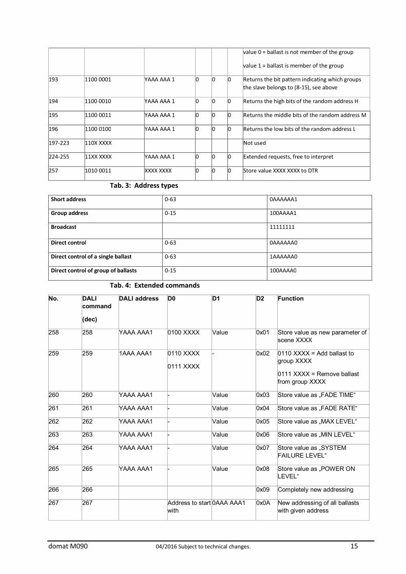
192 1100 0000 YAAA AAA 1 0 0 0 Returns the bit pattern indicating which groups the slave belongs to (0-7)
bit 0 = group 0 etc.
domat M090 04/2016 Subject to technical changes. 15
value 0 = ballast is not member of the group
value 1 = ballast is member of the group
193 1100 0001 YAAA AAA 1 0 0 0 Returns the bit pattern indicating which groups the slave belongs to (8-15), see above
194 1100 0010 YAAA AAA 1 0 0 0 Returns the high bits of the random address H
195 1100 0011 YAAA AAA 1 0 0 0 Returns the middle bits of the random address M
196 1100 0100 YAAA AAA 1 0 0 0 Returns the low bits of the random address L
197-223 110X XXXX Not used
224-255 11XX XXXX YAAA AAA 1 0 0 0 Extended requests, free to interpret
257 1010 0011 XXXX XXXX 0 0 0 Store value XXXX XXXX to DTR
Tab. 3: Address types
Short address 0-63 0AAAAAA1
Group address 0-15 100AAAA1
Broadcast 11111111
Direct control 0-63 0AAAAAA0
Direct control of a single ballast 0-63 1AAAAAA0
Direct control of group of ballasts 0-15 100AAAA0
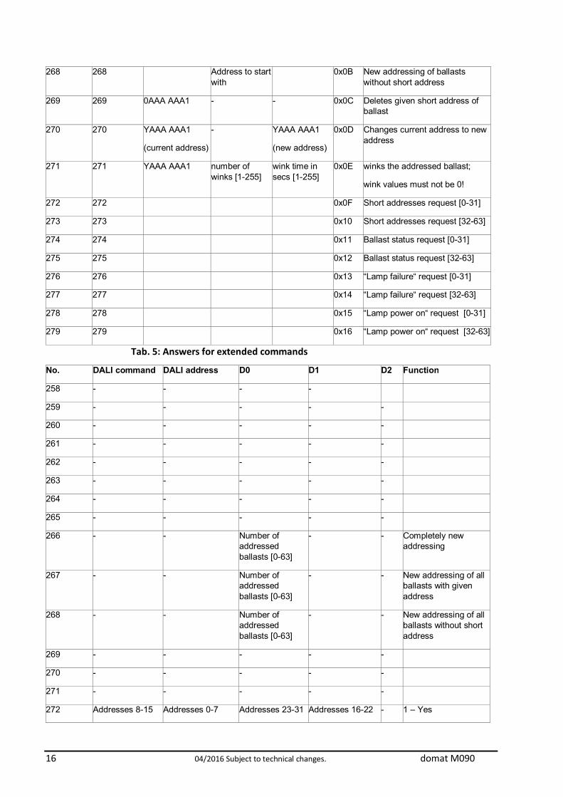
Tab. 4: Extended commands
No. DALI command
(dec)
DALI address D0 D1 D2 Function
258 258 YAAA AAA1 0100 XXXX Value 0x01 Store value as new parameter of scene XXXX
259 259 1AAA AAA1 0110 XXXX
0111 XXXX
- 0x02 0110 XXXX = Add ballast to group XXXX
0111 XXXX = Remove ballast from group XXXX
260 260 YAAA AAA1 - Value 0x03 Store value as „FADE TIME“
261 261 YAAA AAA1 - Value 0x04 Store value as „FADE RATE“
262 262 YAAA AAA1 - Value 0x05 Store value as „MAX LEVEL“
263 263 YAAA AAA1 - Value 0x06 Store value as „MIN LEVEL“
264 264 YAAA AAA1 - Value 0x07 Store value as „SYSTEM FAILURE LEVEL“
265 265 YAAA AAA1 - Value 0x08 Store value as „POWER ON LEVEL“
266 266 0x09 Completely new addressing
267 267 Address to start with
0AAA AAA1 0x0A New addressing of all ballasts with given address
16 04/2016 Subject to technical changes. domat M090
268 268 Address to start with
0x0B New addressing of ballasts without short address
269 269 0AAA AAA1 - - 0x0C Deletes given short address of ballast
270 270 YAAA AAA1
(current address)
- YAAA AAA1
(new address)
0x0D Changes current address to new address
271 271 YAAA AAA1 number of winks [1-255]
wink time in secs [1-255]
0x0E winks the addressed ballast;
wink values must not be 0!
272 272 0x0F Short addresses request [0-31]
273 273 0x10 Short addresses request [32-63]
274 274 0x11 Ballast status request [0-31]
275 275 0x12 Ballast status request [32-63]
276 276 0x13 “Lamp failure“ request [0-31]
277 277 0x14 “Lamp failure“ request [32-63]
278 278 0x15 “Lamp power on“ request [0-31]
279 279 0x16 “Lamp power on“ request [32-63]
Tab. 5: Answers for extended commands
No. DALI command DALI address D0 D1 D2 Function
258 - - - -
259 - - - - -
260 - - - - -
261 - - - - -
262 - - - - -
263 - - - - -
264 - - - - -
265 - - - - -
266 - - Number of addressed ballasts [0-63]
- - Completely new addressing
267 - - Number of addressed ballasts [0-63]
- - New addressing of all ballasts with given address
268 - - Number of addressed ballasts [0-63]
- - New addressing of all ballasts without short address
269 - - - - -
270 - - - - -
271 - - - - -
272 Addresses 8-15 Addresses 0-7 Addresses 23-31 Addresses 16-22 - 1 – Yes

domat M090 04/2016 Subject to technical changes. 17
0 - No
273 Addresses 40-47 Addresses 32-39 Addresses 56-63 Addresses 48-55 - 1 – Yes
0 - No
274 Addresses 8-15 Addresses 0-7 Addresses 23-31 Addresses 16-22 - 1 - Error
0 - OK
275 Addresses 40-47 Addresses 32-39 Addresses 56-63 Addresses 48-55 - 1 - Error
0 - OK
276 Addresses 8-15 Addresses 0-7 Addresses 23-31 Addresses 16-22 - 1 - Error
0 - OK
277 Addresses 40-47 Addresses 32-39 Addresses 56-63 Addresses 48-55 - 1 - Error
0 - OK
278 Addresses 8-15 Addresses 0-7 Addresses 23-31 Addresses 16-22 - 1 - On
0 - Off
279 Addresses 40-47 Addresses 32-39 Addresses 56-63 Addresses 48-55 - 1 - On
0 - Off

18 04/2016 Subject to technical changes. domat M090
Light level control
It is possible to control the light level using two different ways. DALI recognizes direct and indirect light level control. Indirect light level control The command consists of 2 bytes. Byte 1 DALI address (short address / group address / broadcast) Byte 2 Standard or Extended DALI command – see tables above. Direct light level control The command consists of 2 bytes. Byte 1 DALI address; this is the DALI ballast short address, with the first bit of 0. Byte 2 Light level: a number in the range of 0...255 which specifies a value within MIN LEVEL and MAX LEVEL interval. Example: MIN = 100, MAX = 200: to set the light to 50 %, a value of 150 must be sent. This is a way how to control the light level directly without using of groups, scenes etc.
Example of Modbus TCP command
There are 8 "blocks" - (0 to 7) – which represent positions for the DALI commands. To execute a command
- the block(s) must be filled with the data representing the command(s) - bit(s) in Register 5 LSB which corresponds to the block to be executed must
be set. After executing of the command, the info bit in register 5 MSB is set so that the Modbus master can read that the execution was OK. If a command is generating a response, the response is stored in the D0..D2 registers of the particular block. More blocks may be filled at the same time and executed all together by writing a corresponding bit pattern into register 5 LSB. Example: Tx: 00 07 00 00 00 0D 01 10 00 05 00 03 06 0B 05 00 00 00 00 A Modbus TCP example telegram for ballast Adr 6: set to max (DALI function 5). It is written in command block 0 (Modbus register 6, which is Modbus address 5). 00 07 00 00 00 0D 01 Details see Modbus TCP frame structure 10 Modbus F16, write multiple registers 00 05 Modbus address to be written to, address 5 = register 6 00 03 Number of 16bit registers to be written 06 Number of bytes to follow 0B 05 00 00 00 00 The data is 0B 05 for command block 0, other command blocks 1 and 2 are empty (00 00 00 00) - (this is how the client software, with which the example was done, is communicating: it writes three blocks at a time; other clients may only send the first couple of bytes).

domat M090 04/2016 Subject to technical changes. 19
The most important data is 0B 05. 05: LSB = DALI command, see Tab 2 No.5 0B: MSB = 0000 1011 - the structure of a standard DALI command - see Tab 2: Y AAA AAA 1, where Y = 0 for Short address (see Tab 3), and AAA AAA = 000 101 = 5 = DALI address of the ballast. In a similar way more command blocks may be filled, and then activated at the same time. Another Modbus TCP telegram has to activate (execute) this command: Address 6: execute block 0 (write 1 into Modbus register 5, or Modbus address 4) 00 08 00 00 00 09 01 Details see Modbus TCP frame structure 10 Modbus F16, write multiple registers 00 04 Modbus address to be written to, address 4 = register 5 00 01 Number of 16bit registers to be written 02 Number of bytes to follow 00 01 1 at Bit 0 means Execute command block 1. At this time the commands from Block D0 are sent to the DALI bus.
Registers for simple control and status monitoring
To make Modbus communication easier, it is possible to read out statuses and control the ballasts also using a simple Modbus read / write commands to dedicated Modbus registers 30 to 182. These commands are converted to DALI commands in the converter, and sent to the DALI bus (unlike the standard commands, where the Modbus client actually has to compile the DALI telegrams and send them over Modbus). The Modbus client then may assign a separate register or bit to each ballast which makes the Modbus client engineering easier. It is necessary to enable the required functions in Register 30 (see table above) for two reasons:
- this communication may bring extra load to the DALI bus, it is advisable to set e.g. the status update interval to the longest acceptable time
- only enabled command types are sent to the DALI bus – security reason. If these functions are not used, they should be disabled in register 30. Note that if more commands to control a single DALI ballast are set over different registers, the last one is active. Make sure that the Modbus client does not send weird commands over different registers which could spoil the DALI functionality. To use the simple control commands in a proper way, it is necessary to understand the principle of command processing within the M090. There is an internal FIFO queue of 96 commands. The commands are read over the Modbus TCP interface or web pages, and put into the queue. On the queue output, the commands are translated into DALI telegrams, and sent to the DALI interface. There is no feedback between the DALI command execution and the respective Simple command. The Modbus server response to confirm a Simple command receipt only means that the

20 04/2016 Subject to technical changes. domat M090
command has been received by the M090, not that the command has been queued or executed at the DALI bus. There are no exceptions, priorities, nor any other internal logics in the queue. As the DALI bus communication speed is 1200 bps while the Modbus TCP commands travel at a speed of Ethernet, in case that the Simple commands are sent in a fast sequence, it may happen that the queue gets full.
If the queue is full, all incoming Modbus Simple commands are discarded. At the Statistics web page, there is a Dali failure counter item which counts the discarded commands. If this value is increasing steadily, it means that the Simple commands queue is permanently full and the Modbus communication should be less frequent. Always select only the relevant simple command types at the Conf page. It is advised to disable the types of commands which are not used.
Firmware update
With firmware version 13, there are new functions in M090, which requires a specific firmware update process. The firmware update steps are as follows:
- Open the web page of the M090, go to Administration, and upload the new firmware file (z_Upload.bin)
- set the INIT switch at M090 to ON - power off / on the M090 - the IP address of M090 is 192.168.1.99 now - go to the M090 web pages, Conf - click the Write button - connect to the M090 over FTP (name / password: root / root99) - delete all web pages which are in the M090 - copy the new web pages from your PC to the M090 - disconnect the FTP server - set the INIT switch to OFF - power off / on the M090 - set the new IP address of the module, and all other settings.

domat M090 04/2016 Subject to technical changes. 21
Changes in versions
04/2015 – Removing M090/300mA version. 07/2015 – From firmware version 01500 there is indication of bad communication between ballast and M090 converter in register 31-94 MSB bit 0. 10/2015 – Changed maximal working temperature. 11/2015 – Single master function emphasized. 11/2015 – Single master description – enhancement, adding of the Installation section 04/2016 – Information about F16 sector writing added, Modbus table history added.