Manual DALI button interface TA 4 S DALI-2
20
2021-01-14_307569 Manual DALI button interface TA 4 S DALI-2 TA 4 DALI-2 - 4960094
Transcript of Manual DALI button interface TA 4 S DALI-2

2021-01-14_307569
Manual DALI button interface TA 4 S DALI-2
TA 4 DALI-2 - 4960094

Manual DALI button interface TA 4 S DALI-2 2
Contents
1 General 3 1.1 Safety information 3 1.2 Proper use 3 1.3 Explanation of terms 3
2 Function description 4 2.1 Application examples 4 2.2 Overview of available instances 5
3 Technical data 6
4 Product characteristics 7 4.1 Usage 7 4.2 Functionality 7 4.3 Dimensions 8
5 Connection 9
6 Installation 10
7 Settings 11 7.1 Settings via the DALI bus 11
8 Operating modes 12 8.1 Memory bank 2 – push button instance 12 8.2 Memory bank 3 – absolute input device 13 8.3 Assignment of short addresses 16 8.4 Button function C1-C4 16 8.5 Determining measurement values T1/T2 via the DALI bus 16
9 Accessories 18
10 Contact 20

Manual DALI button interface TA 4 S DALI-2 3
1 General
1.1 Safety information
ATTENTION Installation should only be carried out by a qualified electrician!
1.2 Proper use The DALI button interface TA 4 S DALI-2 is a compact DALI-2 controller with 4 inputs for connecting potential-free buttons and 2 inputs for connecting variable resistors, e.g. sliders, potentiometers or various Theben temperature sensors. It can be easily installed in flush-mounted boxes and is intended for indoor installation. TA 4 S DALI-2 is exclusively intended for use as contractually agreed between the manufacturer and the user. Any other use is considered to be unacceptable. The manufacturer does not accept liability for any resulting damages.
1.3 Explanation of terms The TA 4 S DALI-2 DALI button interface is a push button processing unit of an input control device according to standard IEC 62386 Part 301 as well as an absolute input device according to standard IEC 62386 Part 302 and DiiA Guidelines "Clarifications & Recommendations for IEC 62386" Version 1.2, April 2020. The term push button processing unit of an input control device is used in this document in the English spelling "push button input device", absolute input device as "absolute input device" and short address as "short address".

Manual DALI button interface TA 4 S DALI-2 4
2 Function description The TA 4 S DALI-2 button interfaces are integrated into a DALI system. Thanks to the DALI-2 standard, an application controller from any manufacturer may be used. This controller must support standard IEC 62386 Parts 101/103/301 – and if variable resistors or temperature sensors are used – also Part 302. The TA 4 S DALI-2 button interfaces and other DALI components are connected to the DALI line. The DALI supply is provided by the application controller or an external DALI supply. The assignment of the short addresses (random addressing) for the button interfaces is carried out via the application controller. After start-up, the TA 4 S DALI-2 button interface captures the binary states of the connected buttons and transmits this information to the higher-level controller (application controller) as a DALI telegram. If variable resistors or temperature sensors are connected, the measured values are transmitted to the higher-level controller as a DALI telegram (absolute input device).
2.1 Application examples Application with a higher-level controller
Conventional buttons, sliders and Theben temperature sensors can be connected to the TA 4 S DALI-2 button interface for the desired application, also for blinds, lighting control, heating control, etc.

Manual DALI button interface TA 4 S DALI-2 5
Application with a DALI-2 presence detector
For switching or dimming lamps, conventional buttons are connected to the TA 4 S DALI-2 button interface.
2.2 Overview of available instances
Instance no.
Instance name Instance type
Standard Memory bank
0 Absolute input device T1 2 IEC 62386-302 3 1 Absolute input device T2 2 IEC 62386-302 3 2 Button C1 1 IEC 62386-301 2 3 Button C2 1 IEC 62386-301 2 4 Button C3 1 IEC 62386-301 2 5 Button C4 1 IEC 62386-301 2

Manual DALI button interface TA 4 S DALI-2 6
3 Technical data
Operating voltage DALI (in accordance with IEC 62386-101): 10 V – 22.5 V
Power input max. 10 mA
Type of installation 1 Flush-mounted box according to DIN 49073
Type of contact NO contact or opening contact, potential-free
Contact voltage 5 V
Contact current 0.5 mA (5 mA peak)
Output voltage 5 V DC
Debounce time 50 ms
Resistance range for slider or potentiometer 0 … 100 kΩ
Max. temperature measurement range 2 - 25 °C … + 75 °C or 0 °C … + 85 °C
Protection rating IP 20 (IP 40 when installed)
Protection class II (subject to designated use)
Ambient temperature -15 °C … + 50 °C
Pollution degree 2
Rated impulse voltage 4 kV
Connection type DALI Screw terminals
Cable cross-section 0.14 – 1.5 mm² one wire 0.14 – 1.5 mm² fine wire 0.25 – 0.5 mm² fine wire with crimp terminal (with and without plastic sleeve)
Length of connecting wires for buttons or temperature sensor 25 cm
Max. cable length for buttons or temperature sensor 30 m
CE Declaration of Conformity This device corresponds to EN 60669-1/-2-1/-2-5
RCM conformity This device is compliant with the ACMA guidelines.
DALI conformity IEC 62386-101/103/301/302
1 can be installed with conventional buttons/switches in flush-mounted boxes 2 Measurement range depends on the temperature sensor used. Further information can be found in chapter 8.2 Memory bank 3 – absolute input device.

Manual DALI button interface TA 4 S DALI-2 7
4 Product characteristics
4.1 Usage The button interface TA 4 S DALI-2 can be used in many different ways. It can be used for applications such as blinds control, lighting control, heating control, etc. The focus is on applications in residential and commercial construction:
• Office building
• Schools
• Hospitals
• Hotels
• Sports halls or warehouses
Only for use in closed and dry rooms.
4.2 Functionality
• Compact DALI-2 controller with 4 inputs for the connection of potential-free buttons according to standard IEC 62386 Part 301.
• Buttons of contact type "NO contact" or "opening contact" can be used. The contact type can be set in the memory bank.
• Additionally, 2 inputs are available to connect variable resistors, e.g. sliders, potentiometers or various Theben temperature sensors according to standard IEC 62386 Part 302. The sensor is selected in the memory bank.
• The measurement values can be corrected with an adjustable offset if, for example, the measurement deviates from a reference instrument.
• For the inputs for variable resistors or temperature sensors, an adjustable filter is available for noise suppression.
• The DALI bus load of the event telegrams of the measurement values can be flexibly reduced by means of hysteresis.
• The TA 4 S DALI-2 is a DALI bus participant and can be correspondingly addressed according to IEC 62386 Part 103.
• The identification of the button interface is indicated by the LED.
• The TA 4 S DALI-2 button interface is supplied via the DALI bus.
• Easy installation in conventional flush-mounted boxes.
All of the product characteristics are described in detail in the following sections.

Manual DALI button interface TA 4 S DALI-2 8
4.3 Dimensions

Manual DALI button interface TA 4 S DALI-2 9
5 Connection The TA 4 S DALI-2 button interfaces are connected to the DALI line.
For operation of the TA 4 S DALI-2, an external DALI supply is required. This DALI supply must be able to ensure a reliable power supply for all connected DALI participants.
A minimum current of 10 mA per TA 4 S DALI-2 device must be provided.
Plug for connection lead
DALI connection
A connection lead with plug is supplied for connecting buttons C1 to C4, variable resistors or Theben temperature sensors T1 and T2. The cable length is 25 cm and can be extended up to max. 30 m if required.
Connection of buttons C1 to C4 Connection of variable resistors or Theben temperature sensors T1 and T2 BK = Black; BN = Brown; RD = Red; OG = Orange, YE = Yellow; GN = Green; BU = Blue
Only connect potential-free buttons.
Do not connect 230 V to the device. Otherwise the device will be destroyed.

Manual DALI button interface TA 4 S DALI-2 10
6 Installation The TA 4 S DALI-2 button interfaces are installed in conventional flush-mounted boxes according to DIN 49073.

Manual DALI button interface TA 4 S DALI-2 11
7 Settings All settings are configured via the DALI bus.
In its initial delivery condition, the TA 4 S DALI-2 button interface does not yet have a short address.
7.1 Settings via the DALI bus All parameters and configuration commands are set by the application controller via the DALI bus. The TA 4 S DALI-2 button interface supports the parameters and configuration commands according to IEC 62386* Part 103/301/302. Parameters which are not defined by the standard are stored in the memory bank. The default values of the parameters in the factory settings are also according to standard IEC 62386* Part 103/301/302. * incl. DiiA Guidelines „Clarifications & Recommendations for IEC 62386“, version 1.2, April 2020

Manual DALI button interface TA 4 S DALI-2 12
8 Operating modes The TA 4 S DALI-2 button interface is a push button input device according to standard IEC 62386 Part 301 and an absolute input device according to standard IEC 62386 Part 302.
The TA 4 S DALI-2 button interface is delivered and operated with operating mode 0x00 ex works. The operating mode cannot be changed.
8.1 Memory bank 2 – push button instance In memory bank 2, the button contact type of push button instances 2 to 5 is stored.
Memory bank 2
Value range of button contact type: • 0x00: NO contact (factory setting) • 0xFF: opening contact NC
Address Instance Description
Default value
(factory)
RESET value
Value range
Memory type
0x00 Address of last position
in this memory bank 0x03
no change
- ROM
0x01 Indicator byte (defined by
manufacturer) – version of the memory bank
0x01 no
change - ROM
0x02 Memory bank lock byte 0xFF 0xFF 0xFF / 0x55 RAM
0x03 2 Type of contact of button
C1 0x00 0x00
0x00 / 0xFF NVM
0x04 3 Type of contact of button
C2 0x00 0x00 0x00 / 0xFF
NVM
0x05 4 Type of contact of button
C3 0x00 0x00 0x00 / 0xFF
NVM
0x06 5 Type of contact of button
C4 0x00 0x00 0x00 / 0xFF
NVM
0x07-0xFF
Not implemented / reserved
Response NO
no change
- ROM

Manual DALI button interface TA 4 S DALI-2 13
8.2 Memory bank 3 – absolute input device The parameters of absolute input device instances 0 and 1, which are not defined by DALI-2, are stored in memory bank 3.
Address Instance Description
Default value
(factory)
RESET value
Value range
Memory type
0x00 Address of last position
in this memory bank 0x03 no
change - ROM
0x01
Indicator byte (defined by manufacturer) – version of the memory bank
0x01 no
change - ROM
0x02 Memory bank lock byte 0xFF 0xFF 0xFF / 0x55 RAM 0x03 0 Sensor type of sensor T1 0x03 0x03 0x00 – 0x03 NVM 0x04 0 Offset of sensor T1 0x80 0x80 0x01 – 0xFF NVM 0x05 0 Range of sensor T1 0x00 0x00 0x00 / 0x01 NVM 0x06 0 Hysteresis of sensor T1 0x00 0x00 0x00 – 0xFF NVM 0x07 0 Filter of sensor T1 0x02 0x02 0x00 – 0x0B NVM 0x08 0 Beta low of sensor T1 0xE4 0xE4 0x00 – 0xFF NVM 0x09 0 Beta high of sensor T1 0x11 0x11 0x00 – 0xFF NVM 0x0A 1 Sensor type of sensor T2 0x03 0x03 0x00 – 0x03 NVM 0x0B 1 Offset of sensor T2 0x80 0x80 0x01 – 0xFF NVM 0x0C 1 Range of sensor T2 0x00 0x00 0x00 / 0x01 NVM 0x0D 1 Hysteresis of sensor T2 0x00 0x00 0x00 – 0xFF NVM 0x0E 1 Filter of sensor T2 0x02 0x02 0x00 – 0x0B NVM 0x0F 1 Beta low of sensor T2 0xE4 0xE4 0x00 – 0xFF NVM 0x10 1 Beta high of sensor T2 0x11 0x11 0x00 – 0xFF NVM
0x11-0xFF Not implemented / reserved
Response NO
no change
- ROM
Value range of sensor type: • 0x00: Theben sensors, see table below • 0x01: Theben sensor 9070191 • 0x02: any 100 kΩ NTC with known B or beta [K] (see also value range of parameter beta
low/beta high) • 0x03: 100 kΩ variable resistor (factory setting)
Theben sensors Recommended measurement
range
Max. measurement range Sensor type Range 0x00 Range 0x01
9070191, wall installation temperature sensor
0 °C ... 40 °C 0 °C ... 75 °C -25 °C … 75 °C 0x01
9070321, floor sensor 0 °C ... 40 °C 0 °C ... 85 °C -25 °C ... 75 °C 0x00 9070459, room temperature sensor
-10 °C ... 50 °C 0 °C ... 85 °C -25 °C ... 75 °C 0x00
9070489, contact temperature sensor
0 °C ... 80 °C 0 °C ... 85 °C -25 °C ... 75 °C 0x00
9070496, Flush-mounted temperature sensor
0 °C ... 40 °C 0 °C ... 85 °C -25 °C ... 75 °C 0x00

Manual DALI button interface TA 4 S DALI-2 14
Value range of offset The offset can be used to correct the measurement value if, for example, the measurement deviates from a reference device. • The setting range is 0x01 to 0xFF; this corresponds to an offset range of
o -12.7 °C to +12.7 °C or o -12.7 kΩ to +12.7 kΩ
• One unit corresponds to 0.1 °C or 100 Ω
Value range "Range": The "Range" parameter can be used to select temperature sensors with a positive or negative temperature range. • 0x00: Temperature sensors with a positive temperature range (factory setting) • 0x01: Temperature sensor with a negative temperature range
See also chapter 8.5 Measurement values T1/T2 Value range "Hysteresis": The "Hysteresis" parameter can be used to reduce the DALI bus load. The event telegrams are not sent until the measurement value has changed by the value of the set hysteresis. • The setting range is 0x00 to 0xFF; this corresponds to a hysteresis range of
o 0.1 °C to 25.5 °C or o 100 Ω to +25.5 kΩ
• One unit corresponds to 0.1 °C or 100 Ω
Sensor type Offset 0x00, 0x01, 0x02 0x03 0x01: corresponds to -12.7 °C -12.7 kΩ 0x02: corresponds to -12.6 °C -12.6 kΩ ….. ….. ….. 0x80: factory setting 0 °C 0 Ω 0x81: corresponds to +0.1 °C +0.1 kΩ ….. ….. ….. 0xFF: corresponds to +12.7 °C +12.7 kΩ
Sensor type Hysteresis 0x00, 0x01, 0x02 0x03 0x00: factory setting 0.1 °C 100 Ω 0x01: corresponds to 0.1 °C 100 Ω 0x02: corresponds to 0.2 °C 200 Ω ….. ….. ….. 0x80: corresponds to 12.8 °C 12.8 kΩ ….. ….. ….. 0xFF: corresponds to 25.5 °C 25.5 kΩ

Manual DALI button interface TA 4 S DALI-2 15
Value range "Filter": For noise reduction, the filter level can be adjusted. The filter number determines from how many measurement values the average value is calculated. • The setting range is 0x00 to 0x0B
The filter delays the measurement. With a filter number of 0x02, the delay is about 0.2 seconds and with 0x0A about 51.2 seconds.
delay [ms] = 2filter number * 50 ms.
Value range "beta low/beta high": If 0x02 has been selected at the sensor type parameter "NTC with known B or Beta", the associated B or Beta [K] should be set here. B or Beta is a four digit number in [K], which can be found in the NTC sensor data sheet. In order to be stored in the memory bank, the four-digit number must first be converted to hex format and then stored in the beta low and beta high bytes. Example: B or Beta = 4580 which corresponds to Hex 11E4 • Beta low = 0xE4 factory setting • Beta high = 0x11 factory setting • The setting range for beta low is 0x00 to 0xFF and for beta high 0x00 to 0xFF. Summary of setting options for parameters
Sensor type Offset Range Hysteresis Filter Beta low/high
0x00 × × × × 0x01 × × × × 0x02 × × × × × 0x03 × × ×
Filter number Measurement value 0x00 factory setting each measurement value is transmitted
unchanged 0x01 Average value from 2 measurement values (21) 0x02 Average value from 4 measurement values (22) 0x03 Average value from 8 measurement values (23) ….. ….. 0x09 Average value from 512 measurement values
(29) 0x0A Average value from 1024 measurement values
(210) 0x0B Average value from 2048 measurement values
(211)
Manual DALI button interface TA 4 S DALI-2 16
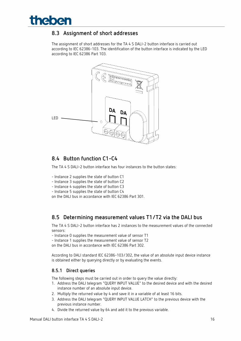
8.3 Assignment of short addresses The assignment of short addresses for the TA 4 S DALI-2 button interface is carried out according to IEC 62386-103. The identification of the button interface is indicated by the LED according to IEC 62386 Part 103.
LED
8.4 Button function C1-C4 The TA 4 S DALI-2 button interface has four instances to the button states: - Instance 2 supplies the state of button C1 - Instance 3 supplies the state of button C2 - Instance 4 supplies the state of button C3 - Instance 5 supplies the state of button C4 on the DALI bus in accordance with IEC 62386 Part 301.
8.5 Determining measurement values T1/T2 via the DALI bus The TA 4 S DALI-2 button interface has 2 instances to the measurement values of the connected sensors: - Instance 0 supplies the measurement value of sensor T1 - Instance 1 supplies the measurement value of sensor T2 on the DALI bus in accordance with IEC 62386 Part 302. According to DALI standard IEC 62386-103/302, the value of an absolute input device instance is obtained either by querying directly or by evaluating the events. 8.5.1 Direct queries The following steps must be carried out in order to query the value directly: 1. Address the DALI telegram "QUERY INPUT VALUE" to the desired device and with the desired
instance number of an absolute input device. 2. Multiply the returned value by 4 and save it in a variable of at least 16 bits. 3. Address the DALI telegram "QUERY INPUT VALUE LATCH" to the previous device with the
previous instance number. 4. Divide the returned value by 64 and add it to the previous variable.

Manual DALI button interface TA 4 S DALI-2 17
Example as pseudo code: Input value = QUERY_INPUT_VALUE () Variable = input value × 4 Input value = QUERY_INPUT_VALUE_LATCH () Variable = variable + input value ÷ 64 8.5.2 Evaluating events An event of an absolute input device can be triggered cyclically or at a certain change of the value. Depending on the type of sensor used, the following steps are necessary to display the obtained value: Temperature sensor with a positive temperature range:
Setting in memory bank 3: sensor type = [0x00], [0x01] or [0x02] Setting in memory bank 3: range = [0x00] Temperature measurement value [°C] = event info/10
Temperature sensor with a negative temperature range:
Setting in memory bank 3: sensor type = [0x00], [0x01] or [0x02] Setting in memory bank 3: range = [0x01]
Temperature measurement value [°C] = (event info – 250) / 10
Variable resistor:
Setting in memory bank 3: sensor type = [0x03]
Measurement value [Ω] = event info x 100

Manual DALI button interface TA 4 S DALI-2 18
9 Accessories Wall installation temperature sensor Recommended measurement range: 0 °C ... 40 °C Item no.: 9070191 Details > www.theben.de/en Floor sensor Recommended measurement range: 0 °C ... 40 °C Item no.: 9070321 Details > www.theben.de/en Room temperature sensor Protection rating IP 65 Recommended measurement range: -10 °C ... 50 °C Item no.: 9070459 Details > www.theben.de/en

Manual DALI button interface TA 4 S DALI-2 19
Contact temperature sensor In cover flap housing for measuring the temperature at pipes and curved surfaces Recommended measurement range: 0 °C ... 80 °C Item no.: 9070489 Details > www.theben.de/en Flush-mounted temperature sensor For flush-mounting Recommended measurement range: 0 °C ... 40 °C Item no.: 9070496 Details > www.theben.de/en
Manual DALI button interface TA 4 S DALI-2 20
10 Contact Theben AG Hohenbergstr. 32 72401 Haigerloch, Germany GERMANY Phone +49 7474 692-0 Fax +49 7474 692-150 Hotline Phone +49 7474 692-369 [email protected] Addresses, telephone numbers, etc. www.theben.de/en


![TANGO - TA-CE3 - LIGMAN...TANGO 33 TA-80553 1 COB 42 W 3377 - 3418 lm AS [46 x 56 ] 3000K CRI80, 4000K CRI80 DALI, On/Off 3.7 kg Square TANGO 34 TA-80561 16 LED 37 W 2417 - 2777 lm](https://static.fdocuments.in/doc/165x107/60fb90bed9a56a42ee04e1a6/tango-ta-ce3-ligman-tango-33-ta-80553-1-cob-42-w-3377-3418-lm-as-46-x.jpg)