LV ltraMOV Series - Littelfuse
12
Varistors Datasheet © 2021 Littelfuse, Inc. Specifications are subject to change without notice. Revised: GD. 07/16/21 1 LV UltraMOV ® Series Radial Leaded Varistors Description Features & Benefits Agency Approvals Absolute Maximum Ratings For ratings of individual members of a series, see Device Ratings and Specifications chart Agency Agency Approval Agency File Number UL 1449 E320116 1 UL 1449 E320116 2 IEC/EN61051 IEC 61051-2 IEC 61051-2-2 IEC 60950-1 (Annex Q) J 50324242 3 CAUTION: Stresses above those listed in "Absolute Maximum Ratings" may cause permanent damage to the device. This is a stress only rating and operation of the device at these or any other conditions above those indicated in the operational sections of this specification is not implied. RoHS ■ Breakthrough in low voltage varistor design provides high peak (up to 10KA) surge current rating ■ Reduced footprint and volume required for surge protection ■ Wide operating voltage range VM(AC)RMS 11V to 95V and V M(DC) 14V to 125V ■ Lead–free, Halogen-Free and RoHS compliant ■ High operating temperature range up to 125ºC (phenolic coating option) ■ 5 model sizes available: 5, 7, 10, 14, and 20mm ■ 10mm, 14mm and 20mm devices are UL Recognized and TUV certified with 800V isolation voltage rating. Applications ■ LED lights ■ Cordless phones ■ Audio and video devices ■ Mobile phone chargers ■ Security systems ■ Fire alarm systems ■ Automation control systems ■ Industrial control contact relays ■ Surge protection device ■ Telecom power systems ■ Wireless base stations Phenolic Coated Epoxy Coated The Littelfuse LV UltraMOV® Varistor Series provides an ideal circuit protection solution for DC voltage applications. The maximum peak surge current rating can reach up to 10kA (8/20μs pulse) to protect against the damage from high peak surge current induced by indirect lightning strike interference, system switching transients, and abnormal fast transients from the power source. Available in five model sizes: 5mm, 7mm, 10mm, 14mm, and 20mm, these device feature a wide voltage range from 14V to 125V. Low Voltage Series Units Continous: Steady State Applied Voltage: AC Voltage Range (V M(AC)RMS ) 11 to 95 V DC Voltage Range (V M(DC) ) 14 to 125 V Transient: Non-Repetitive Surge Current, 8/20µs Waveform (I TM ) 500 to 10,000 A Non-Repetitive Energy Capability, 2ms Waveform (W TM ) 0.8 to 150 J Operating Ambient Temperature Range (T A ) for Epoxy coated -40 to +85 °C Operating Ambient Temperature Range (T A ) for Phenolic coated -40 to +125 °C Storage Temperature Range (T STG ) for Epoxy coated -40 to +125 °C Storage Temperature Range (T STG ) for Phenolic coated -40 to +150 °C Temperature Coefficient (αV) of Clamping Voltage (V C ) at Specified Test Current < 0.01% °C Hi-Pot Encapsulation (Isolation Voltage Capability) for Epoxy coated 2500 V Hi-Pot Encapsulation (Isolation Voltage Capability) for Phenolic coated 800 V Epoxy Coating Insulation Resistance >1,000 MΩ Notes: 1. 10mm, 14mm and 20mm phenolic coated parts are UL Recognized for the US and Canada. 2. All epoxy coated parts (in all sizes) are UL Recognized for the US. 3. 10mm, 14mm and 20mm phenolic coated parts only. Resources Accessories Samples Additional Information
Transcript of LV ltraMOV Series - Littelfuse

Varistors Datasheet
© 2021 Littelfuse, Inc.Specifications are subject to change without notice.
Revised: GD. 07/16/211
LV UltraMOV® SeriesRadial Leaded Varistors
Description
Features & Benefits
Agency Approvals
Absolute Maximum RatingsFor ratings of individual members of a series, see Device Ratings and Specifications chart
Agency Agency Approval Agency File Number
UL 1449 E3201161
UL 1449 E3201162
IEC/EN61051IEC 61051-2
IEC 61051-2-2IEC 60950-1 (Annex Q)
J 503242423
CAUTION: Stresses above those listed in "Absolute Maximum Ratings" may cause permanent damage to the device. This is a stress only rating and operation of the device at these or any other conditions above those indicated in the operational sections of this specification is not implied.
RoHS
Breakthrough in low voltage varistor design provides high peak (up to 10KA) surge current rating
Reduced footprint and volume required for surge protection
Wide operating voltage range VM(AC)RMS 11V to 95V and V M(DC) 14V to 125V
Lead–free, Halogen-Free and RoHS compliant
High operating temperature range up to 125ºC (phenolic coating option)
5 model sizes available: 5, 7, 10, 14, and 20mm
10mm, 14mm and 20mm devices are UL Recognized and TUV certified with 800V isolation voltage rating.
Applications LED lights
Cordless phones
Audio and video devices
Mobile phone chargers
Security systems
Fire alarm systems
Automation control systems
Industrial control contact relays
Surge protection device
Telecom power systems
Wireless base stations
Phenolic Coated
Epoxy Coated The Littelfuse LV UltraMOV® Varistor Series provides an ideal circuit protection solution for DC voltage applications.The maximum peak surge current rating can reach up to 10kA (8/20μs pulse) to protect against the damage from high peak surge current induced by indirect lightning strike interference, system switching transients, and abnormal fast transients from the power source.Available in five model sizes: 5mm, 7mm, 10mm, 14mm, and 20mm, these device feature a wide voltage range from 14V to 125V.
Low Voltage Series Units
Continous:
Steady State Applied Voltage:
AC Voltage Range (VM(AC)RMS) 11 to 95 V DC Voltage Range (VM(DC)) 14 to 125 VTransient:
Non-Repetitive Surge Current, 8/20µs Waveform (ITM) 500 to 10,000 A Non-Repetitive Energy Capability, 2ms Waveform (WTM) 0.8 to 150 JOperating Ambient Temperature Range (TA) for Epoxy coated -40 to +85 °COperating Ambient Temperature Range (TA) for Phenolic coated -40 to +125 °CStorage Temperature Range (TSTG) for Epoxy coated -40 to +125 °CStorage Temperature Range (TSTG) for Phenolic coated -40 to +150 °CTemperature Coefficient (αV) of Clamping Voltage (VC) at Specified Test Current < 0.01% °CHi-Pot Encapsulation (Isolation Voltage Capability) for Epoxy coated 2500 VHi-Pot Encapsulation (Isolation Voltage Capability) for Phenolic coated 800 VEpoxy Coating Insulation Resistance >1,000 MΩ
Notes: 1. 10mm, 14mm and 20mm phenolic coated parts are UL Recognized for the US and Canada.2. All epoxy coated parts (in all sizes) are UL Recognized for the US.3. 10mm, 14mm and 20mm phenolic coated parts only.
Resources Accessories Samples
Additional Information

Varistors Datasheet
© 2021 Littelfuse, Inc.Specifications are subject to change without notice.
Revised: GD. 07/16/212
LV UltraMOV® SeriesRadial Leaded Varistors
Notes: 1. Average power dissipation of transients not to exceed 0.2W, 0.25W, 0.4W, 0.6W or 1W for model sizes 5mm, 7mm, 10mm, 14mm, and 20mm, respectively.2. 10mm, 14mm and 20mm devices are UL recognized with 800V isolation voltage rating.
LV UltraMOV® Series Device Ratings and Specifications
Epoxy Coated Models
Phenolic Coated Models2
Size Disc Dia.
(mm)
Max Continuous Voltage
Varistor Voltage at 1mAMaximum Clamping Voltage
Max Peak Current
(8 x 20µs 1 pulse)
Energy Rating (2ms,
1pulse)
Typical Capaci-tance
f = 1MHz
Part Number
(Base part)Branding
Part Number
(Base part)Branding
VM(AC)RMS VM(DC)
VNOM Min
VNOM Nom
VNOM Max
VC IPK ITM WTM C
(V) (V) (V) (V) (V) (V) (A) (A) (J) (pF)
V05E11P P5E11 V05P11P P5P11 5 11 14 16.2 18.0 19.8 36 1 500 0.8 1300V07E11P P7E11 V07P11P P7P11 7 11 14 16.2 18.0 19.8 36 2.5 1000 2.0 2900V10E11P P10E11 V10P11P P10P11 10 11 14 16.2 18.0 19.8 36 5 2000 4.2 5450V14E11P P14E11 V14P11P P14P11 14 11 14 16.2 18.0 19.8 36 10 4000 8 12000V20E11P P20E11 V20P11P P20P11 20 11 14 16.2 18.0 19.8 36 20 8000 25 26000V05E14P P5E14 V05P14P P5P14 5 14 18 19.8 22.0 24.2 43 1 500 1 1100V07E14P P7E14 V07P14P P7P14 7 14 18 19.8 22.0 24.2 43 2.5 1000 2.2 2450V10E14P P10E14 V10P14P P10P14 10 14 18 19.8 22.0 24.2 43 5 2000 5 4650V14E14P P14E14 V14P14P P14P14 14 14 18 19.8 22.0 24.2 43 10 4000 10 10200V20E14P P20E14 V20P14P P20P14 20 14 18 19.8 22.0 24.2 43 20 8000 28 22200V05E17P P5E17 V05P17P P5P17 5 17 22 24.3 27.0 29.7 53 1 500 1.4 950V07E17P P7E17 V07P17P P7P17 7 17 22 24.3 27.0 29.7 53 2.5 1000 2.8 2100V10E17P P10E17 V10P17P P10P17 10 17 22 24.3 27.0 29.7 53 5 2000 6.5 3900V14E17P P14E17 V14P17P P14P17 14 17 22 24.3 27.0 29.7 53 10 4000 13 8700V20E17P P20E17 V20P17P P20P17 20 17 22 24.3 27.0 29.7 53 20 8000 35 18750V05E20P P5E20 V05P20P P5P20 5 20 26 29.7 33.0 36.3 65 1 500 2 850V07E20P P7E20 V07P20P P7P20 7 20 26 29.7 33.0 36.3 65 2.5 1000 4.2 1750V10E20P P10E20 V10P20P P10P20 10 20 26 29.7 33.0 36.3 65 5 2000 10 3400V14E20P P14E20 V14P20P P14P20 14 20 26 29.7 33.0 36.3 65 10 4000 20 7500V20E20P P20E20 V20P20P P20P20 20 20 26 29.7 33.0 36.3 65 20 8000 58 15000V05E23P P5E23 V05P23P P5P23 5 23 28 32.4 36.0 39.6 71 1 500 2.2 800V07E23P P7E23 V07P23P P7P23 7 23 28 32.4 36.0 39.6 71 2.5 1000 5.0 1650V10E23P P10E23 V10P23P P10P23 10 23 28 32.4 36.0 39.6 71 5 2000 12 3200V14E23P P14E23 V14P23P P14P23 14 23 28 32.4 36.0 39.6 71 10 4000 23 7000V20E23P P20E23 V20P23P P20P23 20 23 28 32.4 36.0 39.6 71 20 8000 70 14000V05E25P P5E25 V05P25P P5P25 5 25 31 35.1 39.0 42.9 77 1 500 2.5 750V07E25P P7E25 V07P25P P7P25 7 25 31 35.1 39.0 42.9 77 2.5 1000 5.5 1500V10E25P P10E25 V10P25P P10P25 10 25 31 35.1 39.0 42.9 77 5 2000 13 2900V14E25P P14E25 V14P25P P14P25 14 25 31 35.1 39.0 42.9 77 10 4000 25 6200V20E25P P20E25 V20P25P P20P25 20 25 31 35.1 39.0 42.9 77 20 8000 77 13500
V05E30P P5E30 V05P30P P5P30 5 30 38 42.3 47.0 51.7 93 1 500 3.1 650
V07E30P P7E30 V07P30P P7P30 7 30 38 42.3 47.0 51.7 93 2.5 1000 7 1350V10E30P P10E30 V10P30P P10P30 10 30 38 42.3 47.0 51.7 93 5 2000 15.5 2550V14E30P P14E30 V14P30P P14P30 14 30 38 42.3 47.0 51.7 93 10 4000 32 5550V20E30P P20E30 V20P30P P20P30 20 30 38 42.3 47.0 51.7 93 20 8000 90 12000V05E35P P5E35 V05P35P P5P35 5 35 45 50.4 56.0 61.6 93 1 500 4 550V07E35P P7E35 V07P35P P7P35 7 35 45 50.4 56.0 61.6 110 2.5 1000 9 1200V10E35P P10E35 V10P35P P10P35 10 35 45 50.4 56.0 61.6 110 5 2000 20 2200V14E35P P14E35 V14P35P P14P35 14 35 45 50.4 56.0 61.6 110 10 4000 40 5000V20E35P P20E35 V20P35P P20P35 20 35 45 50.4 56.0 61.6 110 20 8000 115 10500V05E40P P5E40 V05P40P P5P40 5 40 56 61.2 68.0 74.8 135 1 500 5 500V07E40P P7E40 V07P40P P7P40 7 40 56 61.2 68.0 74.8 135 2.5 1000 11 1000V10E40P P10E40 V10P40P P10P40 10 40 56 61.2 68.0 74.8 135 5 2000 25 1850V14E40P P14E40 V14P40P P14P40 14 40 56 61.2 68.0 74.8 135 10 4000 50 4000V20E40P P20E40 V20P40P P20P40 20 40 56 61.2 68.0 74.8 135 20 8000 140 8500

Varistors Datasheet
© 2021 Littelfuse, Inc.Specifications are subject to change without notice.
Revised: GD. 07/16/213
LV UltraMOV® SeriesRadial Leaded Varistors
Notes: 1. Average power dissipation of transients not to exceed 0.2W, 0.25W, 0.4W, 0.6W or 1W for model sizes 5mm, 7mm, 10mm, 14mm, and 20mm respectively.2. 10mm, 14mm and 20mm devices are UL recognized and TUV certified with 800V isolation voltage rating.
Epoxy Coated Models
Phenolic Coated Models2 Size
Disc Dia.
(mm)
Max Continuous Voltage
Varistor Voltage at 1mAMaximum Clamping Voltage
Max Peak Current
(8 x 20µs 1 pulse)
Energy Rating (2ms,
1pulse)
Typical Capaci-tance
f = 1MHz
Part Number
(Base part)Branding
Part Number
(Base part)Branding
VM(AC)RMS VM(DC)
VNOM
Min
VNOM
Nom
VNOM
MaxVC IPK ITM WTM C
(V) (V) (V) (V) (V) (V) (A) (A) (J) (pF)
V05E50P P5E50 V05P50P P5P50 5 50 65 73.8 82 90.2 135 5 800 5 350
V07E50P P7E50 V07P50P P7P50 7 50 65 73.8 82 90.2 135 10 1750 10 800
V10E50P P10E50 V10P50P P10P50 10 50 65 73.8 82 90.2 135 25 3500 20 1400
V14E50P P14E50 V14P50P P14P50 14 50 65 73.8 82 90.2 145 50 6500 40 3000
V20E50P P20E50 V20P50P P20P50 20 50 65 73.8 82 90.2 145 100 10000 80 6000
V05E60P P5E60 V05P60P P5P60 5 60 85 90 100 110 165 5 800 6 310
V07E60P P7E60 V07P60P P7P60 7 60 85 90 100 110 165 10 1750 12 700
V10E60P P10E60 V10P60P P10P60 10 60 85 90 100 110 165 25 3500 24 1200
V14E60P P14E60 V14P60P P14P60 14 60 85 90 100 110 175 50 6500 50 2500
V20E60P P20E60 V20P60P P20P60 20 60 85 90 100 110 175 100 10000 100 5200
V05E75P P5E75 V05P75P P5P75 5 75 100 108 120 132 205 5 800 7 260
V07E75P P7E75 V07P75P P7P75 7 75 100 108 120 132 205 10 1750 14 600
V10E75P P10E75 V10P75P P10P75 10 75 100 108 120 132 200 25 3500 29 1100
V14E75P P14E75 V14P75P P14P75 14 75 100 108 120 132 210 50 6500 60 2300
V20E75P P20E75 V20P75P P20P75 20 75 100 108 120 132 210 100 10000 120 4800
V05E95P P5E95 V05P95P P5P95 5 95 125 135 150 165 250 5 800 9 200
V07E95P P7E95 V07P95P P7P95 7 95 125 135 150 165 250 10 1750 18 520
V10E95P P10E95 V10P95P P10P95 10 95 125 135 150 165 250 25 3500 36 800
V14E95P P14E95 V14P95P P14P95 14 95 125 135 150 165 250 50 6500 75 1700
V20E95P P20E95 V20P95P P20P95 20 95 125 135 150 165 250 100 10000 150 3700

Varistors Datasheet
© 2021 Littelfuse, Inc.Specifications are subject to change without notice.
Revised: GD. 07/16/214
LV UltraMOV® SeriesRadial Leaded Varistors
Current Energy and Power Dissipation Ratings
100
90
80
70
60
50
40
30
20
10
0-55 50 60 70 80 90 100 110 120 130 140 150
AMBIENT TEMPERATURE ( oC)
PE
RC
EN
T O
F R
ATE
D V
AL
UE
FIGURE 1. CURRENT, ENERGY AND POWER DERATING CURVE
Figure 1A - Power Derating for Epoxy Coated
100
90
80
70
60
50
40
30
20
10
0-55 50 60 70 80 90 100 110 120 130 140 150
Perc
enta
ge o
f Rat
ed V
alue
Ambient Temperature (ºC)
Figure 1B - Power Derating for Phenolic Coated
T1
T2
100
50
0
O1 TIME
PE
RC
EN
T O
F P
EA
K V
ALU
E
O1 = VIRTUAL ORIGIN OF WAVE
t1 = VIRTUAL FRONT TIME = 1.25 x t
(IMPULSE DURATION)
t = TIME FROM 10% TO 90% OF PEAK
t2 = VIRTUAL TIME TO HALF VALUE
EXAMPLE:FOR AN 8/20 s CURRENT WAVEFORM8 s = t1 = VIRTUAL FRONT TIME
20 s = t2 = VIRTUAL TIME TOHALF VALUE
FIGURE 2. PEAK PULSE CURRENT TEST WAVEFORM FOR CLAMPING VOLTAGE
T
Peak Pulse Current Test Waveform for Clamping Voltage
01 = Virtual Origin of WaveT = Time from 10% to 90% of PeakT1 = Rise Time = 1.25 x TT2 = Decay TimeExample - For an 8/20µs Current Waveform:
8µs = T1 = Rise Time20µs = T2 = Decay Time
Figure 2
For applications exceeding 85ºC ambient temperature, the peak surge current and energy ratings must be reduced as shown below.
For applications exceeding 125ºC ambient temperature, the peak surge current and energy ratings must be reduced as shown below.
Varistors Datasheet
© 2021 Littelfuse, Inc.Specifications are subject to change without notice.
Revised: GD. 07/16/215
LV UltraMOV® SeriesRadial Leaded Varistors
V07x11P - V07x40P
V10x11P - V10x40P V14x11P - V14x40P
500400
300
200
100908070605040
30
20
10
MA
XIM
UM
PEA
K VO
LTS
(V)
10-3 10-2 10-1 100 101 102 103
MAXIMUM CLAMPING VOLTAGE
PEAK AMPERES (A)
V07x40PV07x35PV07x30PV07x25P
V07x20P
V07x23P
V07x17PV07x14PV07x11P
MODEL SIZE 7mm
500400
300
200
100908070605040
30
20
10
MA
XIM
UM
PEA
K VO
LTS
(V)
10-3 10-2 10-1 100 101 102 103
PEAK AMPERES (A)
V10x40PV10x35PV10x30P
V10x25P
V10x20P
V10x23P
V10x17PV10x14PV10x11P
MAXIMUM CLAMPING VOLTAGE MODEL SIZE 10mm
600500400
300
200
100908070605040
30
2010-3 10-2 10-1 100 101 102 103
PEAK AMPERES (A)
MA
XIM
UM
PEA
K VO
LTS
(V)
V14x40PV14x35PV14x30P
V14x25P
V14x23P
V14x20P
V14x17PV14x14P
V14x11P
MAXIMUM CLAMPING VOLTAGE
MODEL SIZE 14mm
CLAMPING VOLTAGE FOR V05x11P - V68x68P
600500400300
200
100908070605040
30
20
MA
XIM
UM
PEA
K VO
LTS
(V)
PEAK AMPERES (A)10-2 10-1 100 101 102 103
MAXIMUM CLAMPING VOLTAGE MODEL SIZE 5mm
10
V05x40PV05x35PV05x30PV05x25P
V05x20P
V05x23P
V05x17PV05x14PV05x11P
10-3
V20x11P - V20x40P
MA
XIM
UM
PEA
K VO
LTS
(V)
PEAK AMPERES (A)10 -2 10 -1 10 0 10 1 10 2 10 3 10 410 -310 -5 10 -410 -6
CLAMPING VOLTAGE FOR
CLAMPING VOLTAGE FOR CLAMPING VOLTAGE FOR
CLAMPING VOLTAGE FOR
10
20
30405060708090
600700800900
100
200
300400500
1000MAXIMUM CLAMPING VOLTAGE MODEL SIZE 20mm
V20E11PV20E14PV20E17PV20E20PV20E23P
V20E25PV20E30PV20E35PV20E40P
Maximum Clamping Voltage for 5mm PartsV05x11P - V05x40P
Maximum Clamping Voltage for 7mm PartsV07x11P - V07x40P
Maximum Clamping Voltage for 10mm PartsV10x11P - V10x40P
Maximum Clamping Voltage for 14mm PartsV14x11P - V14x40P
Maximum Clamping Voltage for 20mm PartsV20x11P - V20x40P
V07x11P - V07x40P
V10x11P - V10x40P V14x11P - V14x40P
500400
300
200
100908070605040
30
20
10
MA
XIM
UM
PEA
K VO
LTS
(V)
10-3 10-2 10-1 100 101 102 103
MAXIMUM CLAMPING VOLTAGE
PEAK AMPERES (A)
V07x40PV07x35PV07x30PV07x25P
V07x20P
V07x23P
V07x17PV07x14PV07x11P
MODEL SIZE 7mm
500400
300
200
100908070605040
30
20
10
MA
XIM
UM
PEA
K VO
LTS
(V)
10-3 10-2 10-1 100 101 102 103
PEAK AMPERES (A)
V10x40PV10x35PV10x30P
V10x25P
V10x20P
V10x23P
V10x17PV10x14PV10x11P
MAXIMUM CLAMPING VOLTAGE MODEL SIZE 10mm
600500400
300
200
100908070605040
30
2010-3 10-2 10-1 100 101 102 103
PEAK AMPERES (A)
MA
XIM
UM
PEA
K VO
LTS
(V)
V14x40PV14x35PV14x30P
V14x25P
V14x23P
V14x20P
V14x17PV14x14P
V14x11P
MAXIMUM CLAMPING VOLTAGE
MODEL SIZE 14mm
CLAMPING VOLTAGE FOR V05x11P - V68x68P
600500400300
200
100908070605040
30
20
MA
XIM
UM
PEA
K VO
LTS
(V)
PEAK AMPERES (A)10-2 10-1 100 101 102 103
MAXIMUM CLAMPING VOLTAGE MODEL SIZE 5mm
10
V05x40PV05x35PV05x30PV05x25P
V05x20P
V05x23P
V05x17PV05x14PV05x11P
10-3
V20x11P - V20x40P
MA
XIM
UM
PEA
K VO
LTS
(V)
PEAK AMPERES (A)10 -2 10 -1 10 0 10 1 10 2 10 3 10 410 -310 -5 10 -410 -6
CLAMPING VOLTAGE FOR
CLAMPING VOLTAGE FOR CLAMPING VOLTAGE FOR
CLAMPING VOLTAGE FOR
10
20
30405060708090
600700800900
100
200
300400500
1000MAXIMUM CLAMPING VOLTAGE MODEL SIZE 20mm
V20E11PV20E14PV20E17PV20E20PV20E23P
V20E25PV20E30PV20E35PV20E40P
Varistors Datasheet
© 2021 Littelfuse, Inc.Specifications are subject to change without notice.
Revised: GD. 07/16/216
LV UltraMOV® SeriesRadial Leaded Varistors
V05x50P - V05x95P
2000
1000
500
200MA
XIM
UM
PE
AK
VO
LTS
(V)
PEAK AMPERES (A)0.01 0.1 1 10 100 1000
1000.0010.0001
V05x60P
V05x50P
MAX CLAMPING VOLTAGEMODEL SIZE 5mm
V05x95PV05x75P
MA
XIM
UM
PE
AK
VO
LTS
(V
)
PEAK AMPERES (A)10-2 10-1 100 101 102 10310-3
MAXIMUM CLAMPING VOLTAGE MODEL SIZE 7mm
4,000
3,000
2,000
1,000900800700600500400
300
200
100104
V07x95PV07x75P
V07x60PV07x50P
V07x50P - V07x95P
MA
XIM
UM
PE
AK
VO
LTS
(V
)
PEAK AMPERES (A)10-2 10-1 100 101 102 10310-3
MAXIMUM CLAMPING VOLTAGE MODEL SIZE 10mm
4,000
3,000
2,000
1,000900800700600500400
300
200
100104
V10x95PV10x75P
V10x60PV10x50P
V10x50P - V10x95P
MA
XIM
UM
PE
AK
VO
LTS
(V
)
PEAK AMPERES (A)10-2 10-1 100 101 102 10310-3
MAXIMUM CLAMPING VOLTAGE MODEL SIZE 14mm
4,000
3,000
2,000
1,000900800700600500400
300
200
100104
V14x95PV14x75P
V14x60PV14x50P
V14x50P - V14x95P
Maximum Clamping Voltage for 5mm Parts
Maximum Clamping Voltage for 10mm Parts
Maximum Clamping Voltage for 20mm Parts
Maximum Clamping Voltage for 7mm Parts
Maximum Clamping Voltage for 14mm Parts
10-3 10-2 10-1 100 101 102 104103
1,000
500
300
200
30
PEAK AMPERES (A)
MA
XIM
UM
PE
AK
VO
LTS
(V
)
V20x50P
MAXIMUM CLAMPING VOLTAGE MODEL SIZE 20mm
V20x95PV20x75P
100
50
V20x60P
V20x50P - V20x95P

Varistors Datasheet
© 2021 Littelfuse, Inc.Specifications are subject to change without notice.
Revised: GD. 07/16/217
LV UltraMOV® SeriesRadial Leaded Varistors
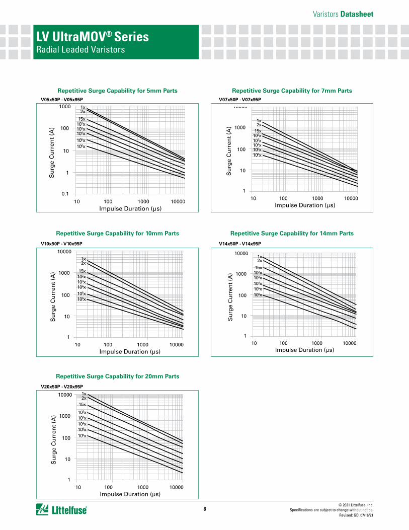
Note: If pulse ratings are exceeded, a shift of VN(DC)(at specified current) of more then +/-10% could result. This type of shift, which normally results in a decrease of VN(DC), may result in the device not meeting the original published specifications, but does not prevent the device from continuing to function, and to provide ample protection.
10 100 1000 10000 10 100 1000 10000
Su
rge
Cu
rren
t (A
)
Impulse Duration (µs)
5MM V05x11P - V05x40P
Su
rge
Cu
rren
t (A
)
Impulse Duration (µs)
7MM V07x11P - V07x40P
1
10
100
1000
10000
1
10
100
1000
10000
Su
rge
Cu
rren
t (A
)
Impulse Duration (µs)
10MM V10x11P - V10x40P
Su
rge
Cu
rren
t (A
)
Impulse Duration (µs)
14MM V14x11P - V14x40P
Su
rge
Cu
rren
t (A
)
Impulse Duration (µs)
20MM V20x11P - V20x40P
1x2x
15x102x103x104x105x106x
0.1
1
10
100
1000
1
10
100
1000
10000
1
10
100
1000
10000
10 100 1000 10000
10 100 1000 10000
10 100 1000 10000
1x2x
15x
102x103x104x105x106x
1x
2x10x
102x103x104x105x106x
1x
2x15x
102x103x104x105x106x
1x
2x
15x102x103x104x105x106x
Repetitive Surge Capability for 5mm PartsV05x11P - V05x40P
Repetitive Surge Capability for 7mm PartsV07x11P - V07x40P
Repetitive Surge Capability for 10mm PartsV10x11P - V10x40P
Repetitive Surge Capability for 14mm PartsV14x11P - V14x40P
Repetitive Surge Capability for 20mm PartsV20x11P - V20x40P
10 100 1000 10000 10 100 1000 10000
Su
rge
Cu
rren
t (A
)
Impulse Duration (µs)
5MM V05x11P - V05x40P
Su
rge
Cu
rren
t (A
)
Impulse Duration (µs)
7MM V07x11P - V07x40P
1
10
100
1000
10000
1
10
100
1000
10000
Su
rge
Cu
rren
t (A
)
Impulse Duration (µs)
10MM V10x11P - V10x40P
Su
rge
Cu
rren
t (A
)
Impulse Duration (µs)
14MM V14x11P - V14x40P
Su
rge
Cu
rren
t (A
)
Impulse Duration (µs)
20MM V20x11P - V20x40P
1x2x
15x102x103x104x105x106x
0.1
1
10
100
1000
1
10
100
1000
10000
1
10
100
1000
10000
10 100 1000 10000
10 100 1000 10000
10 100 1000 10000
1x2x
15x
102x103x104x105x106x
1x
2x10x
102x103x104x105x106x
1x
2x15x
102x103x104x105x106x
1x
2x
15x102x103x104x105x106x
10 100 1000 10000 10 100 1000 10000
Su
rge
Cu
rren
t (A
)
Impulse Duration (µs)
5MM V05x11P - V05x40P
Su
rge
Cu
rren
t (A
)
Impulse Duration (µs)
7MM V07x11P - V07x40P
1
10
100
1000
10000
1
10
100
1000
10000
Su
rge
Cu
rren
t (A
)
Impulse Duration (µs)
10MM V10x11P - V10x40PS
urg
e C
urr
ent (
A)
Impulse Duration (µs)
14MM V14x11P - V14x40P
Su
rge
Cu
rren
t (A
)
Impulse Duration (µs)
20MM V20x11P - V20x40P
1x2x
15x102x103x104x105x106x
0.1
1
10
100
1000
1
10
100
1000
10000
1
10
100
1000
10000
10 100 1000 10000
10 100 1000 10000
10 100 1000 10000
1x2x
15x
102x103x104x105x106x
1x
2x10x
102x103x104x105x106x
1x
2x15x
102x103x104x105x106x
1x
2x
15x102x103x104x105x106x
Varistors Datasheet
© 2021 Littelfuse, Inc.Specifications are subject to change without notice.
Revised: GD. 07/16/218
LV UltraMOV® SeriesRadial Leaded Varistors
Repetitive Surge Capability for 5mm Parts
Repetitive Surge Capability for 10mm Parts
Repetitive Surge Capability for 20mm Parts
Repetitive Surge Capability for 7mm Parts
Repetitive Surge Capability for 14mm Parts
V05x50P - V05x95P
V10x50P - V10x95P
V20x50P - V20x95P
V07x50P - V07x95P
V14x50P - V14x95P
Su
rge
Cu
rren
t (A
)
Impulse Duration (µs)
0.1
1
10
100
1000
10 100 1000 10000
1x2x
15x102x103x104x105x106x
Su
rge
Cu
rren
t (A
)
Impulse Duration (µs)
1
10
100
1000
10000
10 100 1000 10000
1x2x
15x102x103x104x105x106x
Su
rge
Cu
rren
t (A
)
Impulse Duration (µs)
1
10
100
1000
10000
10 100 1000 10000
1x2x
15x102x103x104x105x106x
Su
rge
Cu
rren
t (A
)
Impulse Duration (µs)
1
10
100
1000
10000
10 100 1000 10000
1x2x
15x102x103x104x105x106x
Su
rge
Cu
rren
t (A
)
Impulse Duration (µs)
1
10
100
1000
10000
10 100 1000 10000
1x2x
15x
102x103x104x105x106x

Varistors Datasheet
© 2021 Littelfuse, Inc.Specifications are subject to change without notice.
Revised: GD. 07/16/219
LV UltraMOV® SeriesRadial Leaded Varistors
Humidity Aging+85°C, 85% RH,1000 hours +/-10% typical voltage change
Thermal Shock+85°C to -40°C 10 times +/-10% typical voltage change
Solvent Resistance MIL–STD–202, Method 215
Moisture Sensitivity Level 1, J–STD–020
Lead Material Copper Clad Steel Wire
Soldering Characteristics
Solderability per MIL–STD–202, Method 208
Insulating MaterialCured, flame retardant epoxy polymer meets UL94V–0 requirements
Device Labeling Marked with LF, voltage and date code
Physical Specifications Environmental Specifications
Wave Solder Profile
0
50
100
150
200
250
300
0 0.5 1 1.5 2 2.5 3 3.5 4
TIME(MINUTES)
TEM
PE
RA
TUR
E (º
C)
Maximum Wave 240C
Lead–free Profile
0
50
100
150
200
250
300
0 0.5 1 1.5 2 2.5 3 3.5 4
TIME(MINUTES)
TEM
PER
ATU
RE
(ºC)
Maximum Wave 260C
Non Lead–free Profile

Varistors Datasheet
© 2021 Littelfuse, Inc.Specifications are subject to change without notice.
Revised: GD. 07/16/2110
LV UltraMOV® SeriesRadial Leaded Varistors
Product Dimensions (mm)
Dimen-sion
VRMS VoltageModel
5mm Size 7mm Size 10mm Size 14mm Size 20mm Size
Min. mm (in)
Max.mm (in)
Min. mm (in)
Max.mm (in)
Min.mm (in)
Max.mm (in)
Min.mm (in)
Max.mm (in)
Min.mm (in)
Max.mm (in)
A All - 10 (0.394) - 12
(0.472) - 16 (0.630) - 20
(0.787) - 26.5 (1.043)
A1 All - 13 (0.512) - 15
(0.591) - 19.5 (0.768) - 22.5
(0.886) - 29 (1.142)
ØD All - 7 (0.276) - 9
(0.354) - 12.5 (0.492) - 17
(0.669) - 23 (0.906)
e All 4 (0.157)
6 (0.236)
4 (0.157)
6 (0.236)
6.5 (0.256)
8.5 (0.335)
6.5 (0.256)
8.5 (0.335)
6.5 (0.256)
8.5 (0.335)
e1
11 - 30 1 (0.039)
3 (0.118)
1 (0.039)
3 (0.118)
1 (0.039)
3 (0.118)
1 (0.039)
3 (0.118)
1 (0.039)
3 (0.118)
35 - 95 1.5(0.059)
3.5 (0.138)
1.5 (0.059)
3.5 (0.138)
1.5 (0.059)
3.5 (0.138)
1.5 (0.059)
3.5 (0.138)
1.5 (0.059)
3.5 (0.138)
E11 - 30 - 5.0
(0.197) - 5.0 (0.197) - 5.0
(0.197) - 5.0 (0.197) - 5.0
(0.197)
35 - 95 - 5.6 (0.220) - 5.6
(0.220) - 5.6 (0.220) - 5.6
(0.220) - 5.6 (0.220)
Øb All 0.585 (0.023)
0.685 (0.027)
0.585 (0.023)
0.685 (0.027)
0.76 (0.030)
0.86 (0.034)
0.76 (0.030)
0.86 (0.034)
0.76 (0.030)
0.86 (0.034)
L All 25.4 (1.00) - 25.4
(1.00) - 25.4 (1.00) - 25.4
(1.00) - 25.4 (1.00) -
LTRIM All 2.41 (0.095) 4.69 (0.185)
2.41 (0.095)
4.69 (0.185)
2.41 (0.095)
4.69 (0.185)
2.41 (0.095)
4.69 (0.185)
2.41 (0.095)
4.69 (0.185)

Varistors Datasheet
© 2021 Littelfuse, Inc.Specifications are subject to change without notice.
Revised: GD. 07/16/2111
LV UltraMOV® SeriesRadial Leaded Varistors
Tape and Reel Specifications
CRIMPED LEADS "L2" CRIMPED LEADS "L2"
Crimped Leads "ZT" Crimped Leads "ZT"
Straight Leads "ZS"Straight Leads "ZS"
Under-crimped Leads "ZU"
P1P0
E
DPDH DH
W1
W
F t
W2W0
P
DP
C
DbH0
DD0
H1SEATING PLANE
P2
P1
P0
W0
E
DPDH DH
W1
W
F t
W2
P
DP
C
DbH0
DD0
H1SEATING PLANE
P2
P0
DH
E
DHDP
W1
W
F t
W2
P
DP
DbH
DD0
H1
P1
P2
W0
P1P0
P2
DH
E
DHDP
W1
W
F t
W2W0
P
DP
DbH
DD0
H1
U
P1P0
P2
DH
E
DHDP
W1
W
F t
W2W0
P
DP
DbHo
DD0
H1
Under-crimped Leads "ZU"
P0
U
DH
E
DHDP
W1
W
F t
W2
P
DP
DbHo
DD0
H1
P2
W0
P1
UNDER CRIMPED / IN-LINE LEADS "L3" UNDER CRIMPED / IN-LINE LEADS "L3"
Crimped Leads "ZT" Crimped Leads "ZT"
Straight Leads "ZS"Straight Leads "ZS"
Under-crimped Leads "ZU"
P1P0
E
DPDH DH
W1
W
F t
W2W0
P
DP
C
DbH0
DD0
H1SEATING PLANE
P2
P1
P0
W0
E
DPDH DH
W1
W
F t
W2
P
DP
C
DbH0
DD0
H1SEATING PLANE
P2
P0
DH
E
DHDP
W1
W
F t
W2
P
DP
DbH
DD0
H1
P1
P2
W0
P1P0
P2
DH
E
DHDP
W1
W
F t
W2W0
P
DP
DbH
DD0
H1
U
P1P0
P2
DH
E
DHDP
W1
W
F t
W2W0
P
DP
DbHo
DD0
H1
Under-crimped Leads "ZU"
P0
U
DH
E
DHDP
W1
W
F t
W2
P
DP
DbHo
DD0
H1
P2
W0
P1
5 and 7mm Devices 10, 14, and 20mm Devices
STRAIGHT LEADS "L1" STRAIGHT LEADS "L1"
Refer to next page for dimension measurement specifics.

Varistors Datasheet
© 2021 Littelfuse, Inc.Specifications are subject to change without notice.
Revised: GD. 07/16/2112
LV UltraMOV® SeriesRadial Leaded Varistors
Part Numbering System
Littelfuse Varistor
V 05 E 11 XXXXX
Disc Size05, 07, 10, 14 or 20 mm
CoatingE: EpoxyP: Phenolic
VM(AC)RMS
11V to 95V
P L1 B
Lead-Free and RoHS Compliant
Other Non-StandardOptions
PackagingBlank or B: Bulk PackT: Tape and ReelA: Ammo Pack
5
Lead Spacing OptionsBlank: Standard lead spacing (See Dimensions Table)5: 5mm+/-1.0mm7: 7.5mm+/-1.0mm1: 10mm+/-1.0mm
Lead FormationBlank or L1: StraightL2: CrimpedL3: In-LineL4: Trim/Crimp (Bulk pack only)
Symbol Description Model Size
5mm 7mm 10mm 14mm 20mm
P Pitch of Component 12.7 +/- 1.0 12.7 +/- 1.0 25.4 +/- 1.0 25.4 +/- 1.0 25.4 +/- 1.0
P0 Feed Hole Pitch 12.7 +/- 0.2 12.7 +/- 0.2 12.7 +/- 0.2 12.7 +/- 0.2 12.7 +/- 0.2
P1 Feed Hole Center to Pitch 3.85 +/- 0.7 3.85 +/- 0.7 8.85 +/- 0.7 8.85 +/- 0.7 8.85 +/- 0.7
P2 Hole Center to Component Center 6.35 +/- 1.0 6.35 +/- 1.0 12.7 +/- 0.7 12.7 +/- 0.7 12.7 +/- 0.7
F Lead to Lead Distance 5.0 +/- 1.0 5.0 +/-1.0 7.5 +/- 1.0 7.5 +/- 1.0 7.5 +/- 1.0
h Component Alignment 2.0 Max 2.0 Max 2.0 Max 2.0 Max 2.0 Max
W Tape Width 18.0 +1.0 / -0.5 18.0 +1.0 / -0.5 18.0 +1.0 / -0.5 18.0 +1.0 / -0.5 18.0 +1.0 / -0.5
W0 Hold Down Tape Width 12.0 +/- 0.3 12.0 +/- 0.3 12.0 +/- 0.3 12.0 +/- 0.3 12.0 +/- 0.3
W1 Hole Position 9.0 +0.75 / -0.50 9.0 +0.75 / -0.50 9.0 +0.75 / -0.50 9.0 +0.75 / -0.50 9.0 +0.75 / -0.50
W2 Hold Down Tape Position 0.5 Max 0.5 Max 0.5 Max 0.5 Max 0.5 Max
H Height from Tape Center to Component Base 18.0 +2.0 / -0.0 18.0 +2.0 / -0.0 18.0 +2.0 / -0.0 18.0 +2.0 / -0.0 18.0 +2.0 / -0.0
H0 Seating Plane Height 16.0 +/- 0.5 16.0 +/- 0.5 16.0 +/- 0.5 16.0 +/- 0.5 16.0 +/- 0.5
H1 Component Height 29.0 Max 32.0 Max 36.0 Max 40.0 Max 46.5 Max
D0 Feed Hole Diameter 4.0 +/- 0.2 4.0 +/- 0.2 4.0 +/- 0.2 4.0 +/- 0.2 4.0 +/- 0.2
t Total Tape Thickness 0.7 +/- 0.2 0.7 +/- 0.2 0.7 +/- 0.2 0.7 +/- 0.2 0.7 +/- 0.2
U Undercrimp Width 8.0 Max 8.0 Max 8.0 Max 8.0 Max 8.0 Max
p Component Alignment 3° Max 3º Max 3° Max 3° Max 3° Max
Tape and Reel Specifications (continued)Notes:
Radial devices on tape are supplied with crimped leads, straight leads, or under-crimped leads Leads are offset by product dimension e1 Conforms to ANSI and EIA specifications Can be supplied to IEC Publication 286-2
Disclaimer Notice - Information furnished is believed to be accurate and reliable. However, users should independently evaluate the suitability of and test each product selected for their own applications. Littelfuse products are not designed for, and may not be used in, all applications. Read complete Disclaimer Notice at www.littelfuse.com/disclaimer-electronics.
OPTION CODES: X2855: Nickel Barrier COATED WIRE OPTION -- All standard parts use tinned copper clad steel wire. Nickel Barrier Coated wire is available as an option, consisting of Copper wire with a flashing of Nickel followed by a top coating of Tin. To order append standard model BASE PART number with "X2855". Example: Standard Model: Order As: V05P11P V05P11PX2855