Cineversum Pro Series - LV XG6K - LV WX6K User Manual
64
-
Upload
cineversum -
Category
Documents
-
view
226 -
download
3
description
Cineversum PRO SERIES XGA and WXGA multimedia projectors
Transcript of Cineversum Pro Series - LV XG6K - LV WX6K User Manual


1
Statement
Note:The screen menu and pictures in the manual may slightly differ from the real product.The manual is subject to change without prior notice.

Table of Contents
Table of Contents . . . . . . . . . . . . . . . . . . . . . .2To the Owner. . . . . . . . . . . . . . . . . . . . . . . . . .3Safety Guide . . . . . . . . . . . . . . . . .. . . . . . . . .5
Air Circulation 6Installing the Projector in Proper Directions 6Moving the Projector 6
Part Names and Functions . . . . . . . . . . . . . .7Front 7Back 7Bottom 7Rear Terminal 8Side control and indicators 9Remote Control 10Remote Control Battery Installation 12Operating Range 12
Installation. . . . . . . . . . . . . . . . . . . . . . . . . . .13Positioning the Projector 13Feet Shift Adjustable 13Connecting to a Computer 14Connecting to Video Equipment 15Connecting to Audio Equipment 16Connecting the AC Power Cord 17Lens installation 18
Basic Operation . . . . . . . . . . . . . . . . . . . . . .19Turning On the Projector 19Turning Off the Projector 20How to Operate the On-Screen Menu 21ShortCut Menu 21Full Menu 21Full Menu Bar 22Zoom and Focus Adjustment 23
23Keystone23Auto Setup Function
Sound Adjustment 24Remote Control Operation 25
Computer Inputmputer Input . . . . . . . . . . . . . . . . . . . . . .27Input Source Selection (Computer 1/2) 27Computer System Selection 29Auto PC Adjustment 30Manual Adjustment 31Selecting Image Mode 32Adjusting Image 33Adjusting Screen Size 34
Video Input . . . . . . . . . . . . . . . . . . . . . . . . . .35Selecting Input Source 35Selecting AV System 36Selecting image mode 37Adjusting Image 38Adjusting Screen Size 39
Setting . . . . . . . . . . . . . . . . . . . . . . . . . . . . . .40Setting 40
Information . . . . . . . . . . . . . . . . . . . . . . . . . .48Display Input Source 48
Maintenance and Cleaning . . . . . . . . . . . . .49
Maintenance . . . . . . . . . .. . . . . . . . . . . .. . 53
Appendix . . . . . . . . . .. . . . . . . . . . . .. .. . . 54
Warning Temper indicator 49Cleaning the Filters 50Resetting the Filter Counter 50Covering the lens properly 51Cleaning the Lens 51Cleaning the Projector’s Shell 51Replacing the lamp 52
Changing the lamp model 53
Troubleshooting 54Indicator and project state 57Campatibel PCs 58Configurations of Terminals 59PIN Code memorandum 59Technical Specifications 60Outer Dimensions 61
2

10
3
--Do not cover the vent of the projector. Poor radiationmay shorten the service life or even cause dangers.--Remove the AC power plug if the projector is not to beused for a long time.--Do not project the same image for a long time; otherwise,a residual image may appear on the LCD panel due to itscharacteristic.
Caution
Do not set the projector in greasy, wet, or smokyconditions such as in a kitchen, to prevent a malfunction oraccident. If the projector comes in contact with oil orchemicals, it may become deteriorated.Read and keep this manual for future reference.
The projector must be grounded.
Do not expose the projector to raindrops or highhumidity to avoid a fire or electric shock.
-- This projector produces intense light from the projectionlens. Avoid staring directly into the lens, otherwise eyedamage could be caused. Be especially careful thatchildren do not stare directly into the beam.-- Place the projector in a proper position. Otherwise itmay result in fire hazard.--Leave an appropriate space from the top, sides, and backof the shell in order to ventilate and cool down theprojector. The figures below indicate the minimumdistance to be left. It must be satisfied if the projector isplaced in sealed environment like a cabinet.
Caution
Please read this manual completely before installing andoperating the projector.The projector provides many convenient features andfunctions. Proper operation may enable you to fully utilizethe features and keep it in good condition. Otherwise, itwill not only shorten the service life of the unit, but alsomay cause malfunction, a fire, or other accidents.If your projector cannot work properly, please read thismanual again, check the operating methods and cableconnection, and try the solutions in the part ofTroubleshooting. If the problem still exists, contact thedealer or the service center.The lamp of the projector is a wearing part. The luminancemay decrease after a period of operation and be weakerthan that of a new lamp. This is normal. Please strictlyfollow the steps in Turning on the unit and Turning off theunit to turn on/off the projector, and the requirements inMaintaining and cleaning the projector to service and cleanthe projector regularly. Or the high temperature residualheat may not radiate, greatly shortening the service life ofthe projector and lamp, or even damaging them within ashort period.
CautionElectric shockDo not open
Caution: To reduce the risk of electric shock, do notremove the cover (or back). Nouser-serviceable parts inside except lampreplacement. Refer servicing to qualifiedservice personnel.
The sign indicates the danger of high voltage,i.e., electric shock.
The sign indicates important operating andmaintenance instructions in the manual with theunit.
Environment-friendly use conditions: Theenvironment-friendly life time of theprojector and remote control is 10 years, thelamp (consumable) 5 years, and theprovided batteries (consumable) 5 years.The use conditions of theenvironment-friendly use period are thesame with that of the product. Properlyoperate and effectively maintain theprojector according to the requirements inthis manual.
Safety precautions
To the owner

4
Safety guideAll the safety and operating instructions should be readbefore the product is operated.
Read all of the instructions given here and retain themfor later use. Unplug this projector from AC power supplybefore cleaning. Do not use liquid or aerosol cleaners.Use a damp cloth for cleaning.
Follow all warnings and instructions marked on theprojector.
For added protection to the projector during a lightningstorm, or when it is left unattended and unused for longperiods of time, unplug it from the wall outlet. This willprevent damage due to lightning and power line surges.
Do not expose this unit to rain or use near water... forexample, in a wet basement, near a swimming pool, etc...
Do not use attachments not recommended by themanufacturer as they may cause hazards.
Do not place this projector on an unstable cart, stand,or table. The projector may fall, causing serious injuryto a child or adult, and serious damage to the projector.Use only with a cart or stand recommended by themanufacturer, or sold with the projector. Wall or shelfmounting should follow the manufacturer’s instructions,and should use a mount ing ki t approved by themanufacturers.
An appliance and cart combinationshould be moved with care. Quickstops, excessive force, and unevensurfaces may cause the appliance andcart combination to overturn.
Slots and openings in the back and bottom of the cabinetare provided for ventilation, to ensure reliable operation ofthe equipment and to protect it from overheating.
The openings should never be covered with cloth or othermaterials, and the bottom opening should not be blockedby placing the projector on a bed, sofa, rug, or othersimilar surface. This projector should never be placednear or over a radiator or heat register.
This projector should not be placed in a built-in installation such as a book case unless proper ventilation is provided.
Never push objects of any kind into this projectorthrough cabinet slots as they may touch dangerousvoltage points or short out parts that could result in afire or electric shock. Never spill liquid of any kind on theprojector.
Do not install the projector near the ventilation duct of air-conditioning equipment.
This projector should be operated only from the typeof power source indicated on the marking label. If youare not sure of the type of power supplied, consult yourauthorized dealer or local power company.
Do not overload wall outlets and extension cords as thiscan result in fire or electric shock. Do not allow anythingto rest on the power cord. Do not locate this projectorwhere the cord may be damaged by persons walking onit.
Do not attempt to service this projector yourself asopening or removing Covers may expose you todangerous voltage or other hazards. Refer all servicingto qualified service personnel.
Unplug this projector from wall outlet and refer servicingto qualified service personnel under the followingconditions:a. When the power cord or plug is damaged or frayed.b. If liquid has been spilled into the projector.c. If the projector has been exposed to rain or water.d. If the projector does not operate normally by following the operating instructions. Adjust only those controls that are covered by the operating instructions as improper adjustment of other controls may result in damage and will often require extensive work by a qualified technician to restore the projector to normal operation.e. If the projector has been dropped or the cabinet has been damaged.f. When the projector exhibits a distinct change in performance-this indicates a need for service.
When replacement parts are required, be sure the service technician has used replacement parts specified by the manufacturer that have the same characteristics as the original part. Unauthorized substitutions may result in fire, electric shock, or injury to persons.
Upon completion of any service or repairs to this projector, ask the service technician to perform routine safety checks to determine that the projector is in safe operating condition.

10
10
10° 10°
10° 10°
5
Air circulationOpenings in the cabinet are provided for ventilation. Toensure reliable operation of the product and to protect itfrom overheating, these openings must not be blocked orcovered.
CautionHot air is exhausted from the exhaust vent. When usingor installing the projector, the following precautionsshould be taken.--Do not put any flammable objects, or spray can nearthe projector. Hot air is exhausted from the air vents.--Keep the exhaust vent at least 1 m away from anyobjects.--Do not touch a peripheral part of the exhaust vent,especially screws and metallic part. This area willbecome hot while the projector is being used.--Do not put anything on the projector. Objects put on thecabinet will not only get damaged but also may causefire hazard by heat.Cooling fans are provided to cool down the projector.The fan’s running speed is changed according to thetemperature inside the projector.
Air intake vent Air intake vent
Exhaust vent
Air intake vent
Caution on ceiling mountingFor ceiling mounting, you need the ceiling mount kitdesigned for this projector.When not mounted properly,the projector may fall, causing hazards or injury. Fordetails, consult your dealer. The warranty on thisprojector does not cover any damage caused by use ofany non-recommended ceiling mount kit or installationof the ceiling mount kit in an improper location.
Safety guide
Installing the projector in proper directionsInstall the projector properly for normal operation.Improper installation may reduce the lamp lifetime andcause a fire hazard. The projector may project imagesupward, downward, or slantwise when it is installedvertically to the surface level. Keep the bottom of theprojector upward for installation when it is tilteddownward.
To flip an image, set the ceiling function ON.Positioning precautions
Do not roll the projector over 10degrees from side to side.
Do not point the projector down toproject an image.
Do not roll the projector over 10 degrees from
side to side when projecting an image upward.
Do not tilt the projector over 10 degrees fromside to side when projecting an image downward.

6
Safety guide
Moving the projector
Caution on lens protectorBefore use, remove the lens protector. To move the projector, press andhold the Shift or lens key more than 5 seconds to center the lens back.Then, install the protector to protect the lens.
Lens protector
When moving the projector, retract the adjustable feet to prevent damage to the lens and cabinet.Put it into a suitable case when the projector is not in use for a long period.
Caution in moving or transporting the projector
– Do not drop or bump the projector, otherwise damages or malfunctions may result.– When carrying the projector, use a suitable carrying case.– Do not transport the projector by courier or any other transport service in an unsuitable transportcase. This may cause damage to the projector. For information about transporting the projector bycourier or any other transport service, consult your dealer.– Do not put the projector in a case before it is cooled enough.
Caution in handling the projector
When lifting or moving the projector, do not hold the lensor the directive hood to prevent damage to the lens or theunit.Handle the projector with care. Do not drop or bump it toavoid strong force, or place other objects on the cabinet.
Caution
The lens of the projector is electric.When operating the projector, payattention to the following conditions.When the lens is rotating, do nottouch it, otherwise your fingers mayget hurt.Do not allow a child to touch the lens.
Do not hold the lens and the peripheral part.
⑮
⑭
⑮
⑯ ⑯
7
Part names and functions
(1) Lens release button(2) Indicator(3) Lamp cover(4) Speaker(5) Lens cap(6) Projector lens(7) Decorative cover(8) Remote receiver (Front & top)(9) Side control panel
(10) Exhaust vent
CautionHot air is exhausted from the exhaust vent. Donot put heat-sensitive objects near this side.
(11) Remote receiver (Back)(12) Terminals and connectors(13) Air filter and air-intake vent(14) Power cord connector
(15) Safety lock(16) Adjustable feet
Front
Back
Back
Bottom

7 10986 11
1 5432
HDMI
INPU
T2IN
PUT1
MONITOR OUT SCART IN
COMPUTER IN2 COMPUTER IN1
3/4HS/CS VS
OUT
4
VIDEO 2
1
8
(1) Network portUsed to connect the network cable.
(2) CONTROLWhen using RS232 to control the projector,please connect the serial control line to thisterminal.
(3) COMPUTER IN2/MONITOR OUT- Used to connect the computer output.- Used to output the analog signals from (4) or(6) to the other monitor.
(4) COMPUTER IN1/SCART IN- Used to connect a computer or RGB SCARToutput.
(5) HDMIUsed to connect the HDMI digital output.
(6) BNC input jacksConnect the component or composite videooutput from video equipment to VIDEO 2terminal, or connect the RGBHV format (5line system) signal to G, B, R, Hs, and Vsjacks.
(7) S-VIDEOUsed to connect the S-video output of videoequipment.
(8) Component (video) input jacksConnect the component signals to theseterminals or connect the component videosignal to VIDEO1/Y terminal.
(9) AUDIO 3/4Used to connect the audio output from videequipment (INPUT 3 or INPUT 4). When theaudio output is monaural, connect it to L(MONO) jack.
(10) AUDIO 2Connect the audio output from videoequipment connected to (3) or (4) to this jack(stereo).
(11) AUDIO OUTUsed to connect the audio output (stereo)connected to (9) or (10).
Part names and functionsRear terminal
Rear terminal

9
(1)
(2) INPUT buttonTo select an input source.
(3) SHIFT buttonTo enter the lens shift mode.
(4
4
) AUTO SETUP buttonTo perform various settings configuredautomatically, including the input sourcesearch function and auto PC adjust function.
(5) ZOOM buttonTo zoom in/out images.
(6) MENU buttonTo open or close the screen menu.
(7) FOCUS buttonTo adjust the focus.
(8) ON/STAND-BY button
(9)
POWER indicator– Lights red when the projector is in stand-by
mode.– Lights green during operations.– Flashes green in the Power management mode
(10)
LAMP REPLACE indicatorIt turns orange when the life of the projectionlamp draws to an end.
(11)
WARNING TEMP indicator It flashes red when the internal projectortemperature is too high.
(12)
SHIFT indicatorIt lights blue when the projector lens ismoving.It lights blue when the projector lens ismoving to the end.
(13)
(1 ) FOCUS indicatorIt lights green when zooming in/out.
To turn on/off the projector.
Part names and functionsSide control and indicators
Side control Indicators (Top panel)
SELECT button–Enter full menu from shortcut.
–Execute the selected item.–Expand or compress the image in the Digital zoom
Mode.
4
Point (VOLUME +/–) buttons–Select an item or adjust the value in the
On-Screen Menu.–Pan the image in the D. Zoom +/- mode.–Adjust the volume level.
25
26
27
28
29
S.MENU
F.MENU
(VOLUME – / + )
VIDEO 1
ON-STANDBY
HDMI
COMPUTER
VIDEO 2
RGBHV
10
TIMER
KEYSTONE
SELECT
SCART
COMPONENT
S-VIDEO
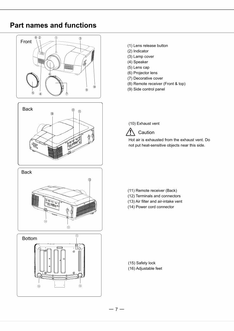
Part names and functions
Remote control
Turn the projector on or off.
button
Select HDMI input source.
Select VGA1 or VGA2 input source.
Select RGBHV input source.
Select VIDEO 1 input source.
Select VIDEO 2 input source.
Open or close the full screen menu.
Open or close the shortcut menu.
button
button
button
button
button
button
button
button
button
button
button
button
button– Select an item or adjust the value in the
on-screen menu.– Pan the image in Digital zoom + mode.– Adjust the volume level ( ) .
button
Select SCART input source.
Select the component input source.
Select the S-Video input source.
-Access the full menu or select an item in themenu.
Calibrate keystone type distortion.
Enable the timer function.

11
MUTE
BLANK
FREEZE
IMAGE
㉔
LAMP
㉒
㉓
FOCUS
VOLUME+
㉑
VOLUME-
ZOOM
LENS
SCREEN
D.ZOOM+
AUTOSET
D.ZOOM-
㉑
㉒
㉔
⑳㉓
Select the lens shift mode.
Zoom in/out images.
Select a screen display mode.
Select the digital zoom - mode.
Enter the AUTOSET mode.
Select the digital zoom + mode.
Decrease the volume level.
Adjust the focus.
Select the lamp mode.
Temporarily close the on-screen image.
Freeze the projected image.
Select the image mode.
Mute the sound.
Increase the volume level.
button
button
button
button
button
button
button
button
button
button
button
button
button
button
To ensure safe operation, observe
the following precautions:– Do not bend, drop, or expose the remotecontrol to moisture or heat.– For cleaning, use a soft dry cloth. Do notapply benzene, thinner, splay, or any otherchemicals.
Part names and functions
Remote control

12
1 2 3
5M
5M
To ensure safe operation, please observe the following precautions:
Use two (2) AAA or LR03 type alkaline batteries.Always replace batteries in sets.Do not use a new battery with a used battery.Avoid contact with water or liquid matter.Do not expose the remote control to moisture or heat.Do not drop the remote control.If the battery has leaked on the remote control, carefullywipe the case clean and install new batteries.Risk of explosion if a battery is replaced by an incorrect type.Dispose of used batteries according to the instructions.
Operating rangePoint the remote control toward the projector when pressing anybutton. The maximum operating range for the remote control isabout 5 meters and 60 degrees.
Adjustable feet
Projection angle can be adjusted up to 5.0 degree with theadjustable feet.Rotate the adjustable feet to lift the projector to a certain height.During lifting, rotate the two feet clockwise.To lower or retract the adjustable feet, rotate the two feetcounterclockwise.Keystone distortion of the projected image can be corrected bymenu operation.
Adjustable feet
Part names and functions
Remote control battery installation
Open the batterycompartment lid.
Install new batteries into thecompartment.
Replace the compartmentlid.
For correct polarity(+ and –), be surebattery terminals are incontact with pins in thecompartment.

13
50%
10%
Installation
Positioning the projectorNoteThe brightness in the room has a great influence on picture quality. It is recommended to limit the ambient lightingin order to get the best image.All measurements are approximate and may vary from the actual sizes.
Lens shift adjustmentProjection lens can be moved from side to side and up anfunction makes the positioning of images easy on the screen.
The displayposition can beshifted upward upto 50% elevationof the display. The display
position can beshifted downwardup to 50%elevation of thedisplay.
When the lens is shifted to top. When the lens is shifted to bottom.
When the lens is shifted to leftmost. When the lens is shifted to rightmost.
The displayposition can beshifted to the leftup to 10% widthof the display.
The display position canbe shifted to the right upto 10% width of thedisplay.
Adjusting range
Shifting rangeWhen the lens isshifted to the center.
40”
813 x 610
1.024 m
1.705 m
100”
2032 x 1524
2.628 m
4.334 m
200”
4064 x 3048
5.301 m
8.716 m
300”
6096 x 4572
7.974 m
13.098 m
400”
8128 x 6096
10.647 m
17.481 m
17.481 m
400”
400”
WIDE
40”
862 x 539
1.093 m
1.777 m
100”
2154 x 1346
2.8 m
4.514 m
200”
4308 x 2692
5.645 m
9.077 m
300”
6462 x 4039
8.489 m
13.64 m
400”
8616 x 5385
11.319 m
18.187 m
11.319 m
18.187 m
2.8 m
5.645 m
8.489 m
2.628 m
5.301 m
7.974 m
10.647 m
Diagonal( )
Max. frame
Min. frame
Diagonal( )
Max. frame
Min. frame

HDMI
INP
UT2
INP
UT1
MONITOR OUT SCART IN
COMPUTER IN2 COMPUTER IN1
3/4HS/CS VS
OUT
4
VIDEO 2
1
14
G B R H V
••
••
Installation
Connecting to computer (Digital and analog RGB)
Cables used for connection ( =Cables are not supplied with the projector.)VGA cable (1) Serial crossover cable (F-F) *BNC cable * HDMI cable *
Monitor output Serial output Monitor input * Monitor output HDMI terminal
BNC cable Serial crossover cable VGA cable VGA cable HDMI cable
Control terminal Analog output Analog input HDMI
Unplug the power cords of both the projector and external equipment from the AC outlet before connecting the cables.

15
HDMI
INP
UT2
INP
UT1
MONITOR OUT SCART IN
COMPUTER IN2 COMPUTER IN1
3/4HS/CS VS
OUT
4
VIDEO 2
1
••••
Unplug the power cords of both the projector and external equipment from theAC outlet before connecting the cables.
Installation
Connecting to video equipmentCables used for connection (*=Cables are not supplied with the projector.)
Video cable (RCA* 1 or RCA*3) *BNC cable (BNC*1 or BNC*3) *S-Video cable *Scart-VGA cable *
Compositevideo
Componentvideooutput
Compositevideo
S-Videooutput
RGB Scart 21-pinoutput
RCA cable S-Video cable Scart-VGA cable
Video Y-Pb/Cb-Pr/Cr
VideoAnalog otput S-VIDEO Analog input
Refer to theanalog outpusignal table asshown in thefigure above.

3/4
OUT
1
16
(R) (L)
(R) (L)
(R) (L)
or
Unplug the power cords of both the projector and external equipment from the AC outlet before connectingthe cables.
InstallationConnecting to audio equipmentCables used for connection (* =Cables are not supplied with the projector.)
Audio cable *
External audio equipment
Audio cable
Audio cable(Stereo)
Audio output
Audio input
(Stereo)Audio cable
Audio output
Audio cable(Stereo) Audio cable
(Stereo)
Audio IN

17
Note:Using incorrect power cord may influence the product performance, or even cause hazards like an electric shockor fire. To ensure the product performance and security, please apply the cable of the same model with the originalone.Common connecting cables include the AC power cord, vari ous VGA cables, audio cable, video cable, and serialcontrol cable.
Installation
Connecting to the AC power cord
This projector uses nominal input voltages of 100–240 V ACcorrect input voltage. It is
designed to work with a single-phase power system having aduce the risk of electrical
shock, do not plug into any other type of power system. Ifyou are not sure of the type of power being supplied, consult
service station. Connect theprojector with all peripheral equipment before turning it on.
Connect the AC power cord(supplied) to the projector.
The AC outlet should be near this equipment and must be easily accessible.
Note:
Note on the power cordAC power cord must meet the requirements of the country where you use the projector.Confirm the AC plug type with the chart below and proper AC power cord must be used.If the supplied AC power cord does not match
Projector side AC outlet side
To power cord connectoron your projector.
Ground
To the AC outlet.(100-240 V AC)
and it automatically selects the
grounded neutral conductor. To re
your authorized dealer or
Unplug the AC power cord when the projector is not in use. When theprojector is connected to an outlet with AC power cord, it is in stand-bymode and consumes a little electric power.

18
123
1
3
2
Installation
Lens installationFollow the instructions below to install the lens upon replacing or using the provided lens. For the specification of
projector lens, contact your dealer.
Removing the lens Lens release button
Shift the lens to the center with the lens shiftfunction.
Turn off the projector, and unplug the AC powercord.
Press and hold the lens release button on the top counterclockwiseuntil the lens cannot be rotated.Draw it out slowly from the projector.
Caution
Do not drop the lens when handling.
Installing the lens
Remove the lens decorator.
Align the red point on the lens with that on theprojector to install the lens.
Rotate the lens clockwise slowly until it clicks.Make sure that the lens isthe projector.
Caution
While installing the lens, donot hold the release button.
Notes on lens installation
Do not touch or remove any part except lens and its relative part. This may causea malfunction, electric shock,fire or other hazards.Make sure the mode of the lens is compatible with your projector before installing or replacing the lens.For information about the lens and its installation, contact the local dealer.
Red point
19
Basic operation
Caution on handling the PIN codeIf you forget your PIN code, the projectorcan no longer be started. Take a specialcare in setting a new PIN code; writedown the number in a column on page 59of this manual and keep it at hand. Shouldthe PIN code be missing or forgotten,consult your dealer or service center.
Turning on the projector1 Complete peripheral connections (with a computer, VCR, etc.) before
turning on the projector.2 Connect the projector’s AC power cord into an AC outlet. The
POWER indicator turns red. Open the lens cap.3 Press the ON/STAND-BY button on the top control or on the remote
control. The POWER indicator becomes green and the cooling fansstart to operate. The preparation display appears on the screen and thecount down starts.
4 If the projector is locked with a PIN code, a PIN code Input DialogBox appears. Enter the PIN code as instructed below.
The preparation displaydisappears after 10 seconds.
Note:When the
Logo select
option is set to be "Off,” the logo will not bedisplayed on the screen.When the display function is set to be"Off,” the logo and countdown will not be displayedon the screen.During the countdown period, all operations areinvalid except shutdown.
Enter a PIN codeSelect a number by pressing the buttons,and then press the button to fix the numberand move the cursor. The number changes to "*".If you fixed an incorrect number, move the cursorto the number you want to correct by pressing the
button, and then select the correct number bypressing the buttons.Repeat this step to complete entering a three-digitnumber.After entering the three-digit number, move thecursor to "Set", then you can start to operate theprojector.If you entered an incorrect PIN code, the "PINcode" and the number (***) turn red. Enter thecorrect PIN code all over again.
What is PIN code?PIN (Personal Identification Number) code is a security code thatallows the person who knows it to operate the projector. Setting thePIN code prevents unauthorized use of the projector.
A PIN code consists of a three-digit number. Refer to the PIN codelock function in the Setting Menu on pages 46 for locking operationof the projector with your PIN code.
Move the cursor to Set, and press SELECT.

20
1
2
3
Basic operation
Turning off the projector
Press the ON/STAND-BY button on the side control or onthe remote control, and “Power off?” appears on the screen.
Press the ON/STAND-BY button again to turn off theprojector. The POWER indicator starts to flash red, and thecooling fans keep running. (You can select the level of thefans’ quietness and running speed.) At this time you canunplug the AC power cord even if the fans are still running.
When the projector has cooled down enough to be turned onagain, the POWER indicator stops flashing.
“Power off” disappears after 4 seconds.
To maintain the lamp life, once you turn theprojector on, wait at least 5 minutes before turning if off.
Do not operate the projector continuously withoutreset. Continuous use may result in shortening the lamp life.Turn off the projector and let it stand for about an hour inevery 24 hours.
Note:When the On start function is “On,” this projector is turned on automatically by connecting the AC power cordto an AC outlet (p. 44).The running speed of cooling fans is changed according to the temperature inside the projector.Do not put the projector in a case before the projector is cooled enough.If the WARNING indicator flashes or emits a red light, see “Warning Indicator”.While the POWER indicator is flashing, the lamp is being cooled down and the projector cannot be turned on.Wait until the POWER indicator turns red to turn on the projector again.The fan rotation will terminate directly if the AC power cord is unplugged immediately after the projector isturned off.The projector can be turned on after the POWER indicator turns red. The waiting time to restart will beshortened when the normal power-off processing for fan cooling is completed, comparing with the time the ACpower cord is immediately unplugged after the power-off.
Power off ?

21
HDMIComputer 1Computer 2
RGBHVSCART
Basic operation
How to operate the on-screen menuRemote control
The projector can be adjusted or set via the on-screenmenu, including Shortcut menu and Full menu.General operations are available via the shortcut menu.A full menu features multiple structures. Each mainmenu can be divided into several levels of submenus,and submenus are also divided into several levels ofsub-submenus. For each adjustment and settingprocedure, refer to the respective sections in thismanual.
Shortcut menu
Press the menu button on the side control or the S.MENU button on the remote control to display the shortcutmenu.
Press the buttons to select a menu entry. Press the buttons to adjust settings.
Press the menu button on the side control or the S.MENU button on the remote control again to quit the shortcutmenu. Or press the SELECT button again to show the full menu.
Full menu
Press the menu button on the side control to displaythe shortcut menu, and then the SELECT buttonagain to show the full menu. Or you may directlypress the F.MENU button to show it.
Press the buttons to select an entry in themain menu and then the button to access thesubmenu.
Press the buttons to select your requiredentry, and then press SELECT or the button toset or enter the submenu.
Press the buttons to adjust settings orswitch among the entries. Press the SELECT buttonfor corresponding operation and then return to thesubmenu.
Press the button to return to the previous menu.Press the F.MENU on the remote control again toquit the full menu mode.
Full menu
Indicators
Select button
buttonFull menu button
Input
InputComponent
SystemExit
S-videoVideo 1Video 2
NextMove Next

22
HDMIComputer 1Computer 2
RGBHVSCART
MENU SELECT
Basic operation
Full menu barMain menu Sub menu
(1) PC adjustment menuUsed to adjust parameters, like , to match with VGA input signal format.
(2) Screen menuIf a computer is selected as a signal source, the following setup options for the image size are available: Normal, True,Wide, Full, Custom, or Digital zoom +/-.If video equipment is selected as a signal source, the following setup options for the image size are available: Normal,Wide, or Custom.
(3) Image select menuThe available image modes are: Dynamic, Normal, Cinema, Blackboard (Green), Colorboard, or User Image.
(4) Image adjust menuIf a computer is selected as a signal source, the following image adjusting options are available: Contrast, Brightness,Color temp, Red,Green,Blue, Sharpness, and Gamma.If video equipment is selected as a signal source, the following image adjusting options are available: Contrast,Brightness, Color , T i n t , Red,Green,Blue, Sharpness, Gamma, Noise reduction, and Progressive.
(5) Input menu
Used to select input source, HDMI, Computer 1, Computer 2, Component, Video 1, Video 2, S-Video, RGBHV or SCART.(6) Sound menu
Used to adjust the volume level or mute the sound.(7) Setting menu
Used to configure the projector operation settings.(8) Network menu
Used to access the network function.
(9) Information menuUsed to display information.
Input
InputComponent
System
Exit
S-videoVideo 1Video 2
Move Next Next
Auto PC adj. Fine sync Total dots Horizontal Vertical Clamp Di s play area HDisplay area V Reset Mode free Store

23
Basic operation
Auto setup functionThis function is available just by pressing the Auto Setupbutton on the top control. The system then automaticallyperforms various settings in the setup menu, including inputsource search, and auto computer adjustment.
Arrow keys
Keystonecorrectingbutton
Auto setup
Remote control
Lens shift Control panel (on the right side of the projector body)
1.Use SHIFT on the control panel or LENS of the remote control to adjust the lens.
2. “Lens shift” will jump out on the screen. According to the instruction, please use
distortion. The maximum shift range is ±50°vertically and ±10°horizontally.
3.Push SHIFT on the control panel or LENS of the remote control and hold on for at least 5 seconds to reset the lens to the center
Note:
urn red.
Zoom adjustment1.Push ZOOM on the control panel or ZOOM of the remote control to enter zoom adjustment.
2. “Zoom” will jump out on the screen. According to instruction, please
Focus adjustment 1.Push FOCUS on the control panel or FOCUS of the remote control to enter focus adjustment.2. “Focus” will jump out on the screen. According to instruction, please
Focus+
Zoom+
button
button
Shift
LENS
Lens shift
24
16
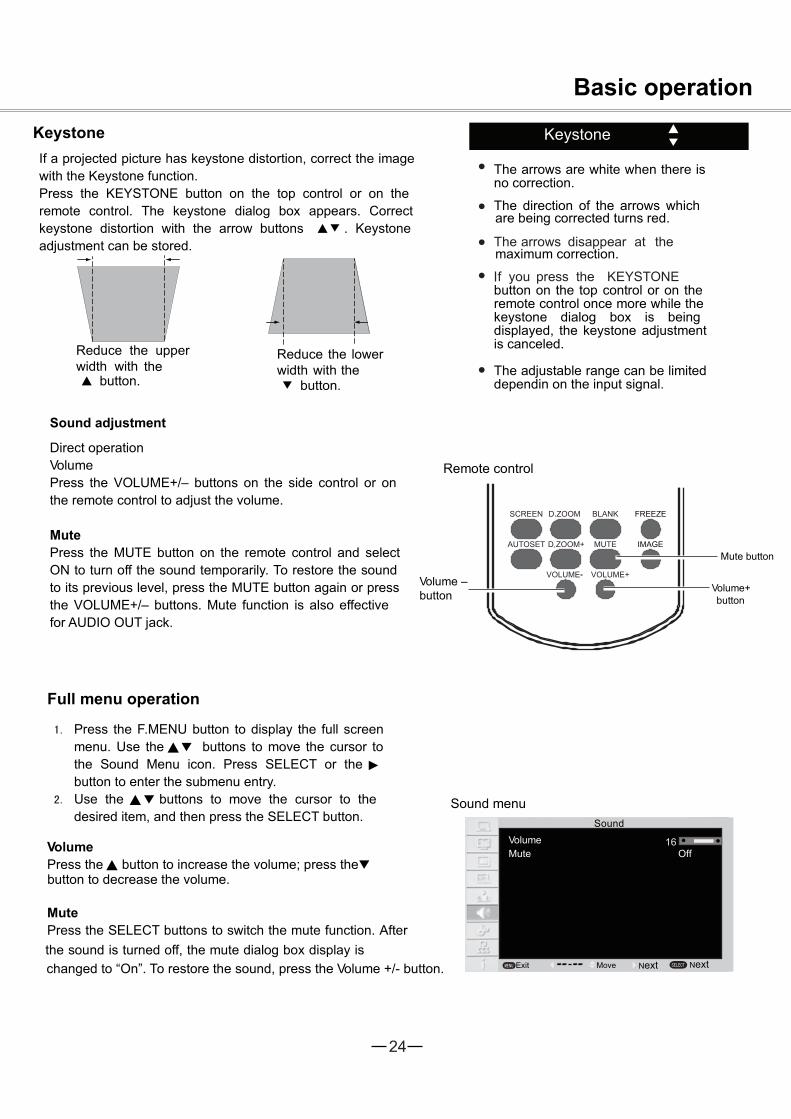
The arrows are white when there isno correction.
The direction of the arrows whichare being corrected turns red.
maximum correction.
button on the top control or on theremote control once more while thekeystone dialog box is beingdisplayed, the keystone adjustmentis canceled.
The adjustable range can be limiteddependin on the input signal.
KeystoneKeystoneIf a projected picture has keystone distortion, correct the imagewith the Keystone function.Press the KEYSTONE button on the top control or on theremote control. The keystone dialog box appears. Correctkeystone distortion with the arrow buttons . Keystoneadjustment can be stored.
Reduce the upperwidth with the
button.
Reduce the lowerwidth with the
button.
Sound adjustment
Direct operationVolumePress the VOLUME+/– buttons on the side control or onthe remote control to adjust the volume.
Remote control
MutePress the MUTE button on the remote control and selectON to turn off the sound temporarily. To restore the soundto its previous level, press the MUTE button again or pressthe VOLUME+/– buttons. Mute function is also effectivefor AUDIO OUT jack.
Volume –button
Sound menu
Full menu operation
Press the F.MENU button to display the full screenmenu. Use the buttons to move the cursor tothe Sound Menu icon. Press SELECT or thebutton to enter the submenu entry.Use the buttons to move the cursor to thedesired item, and then press the SELECT button.
VolumePress the button to increase the volume; press thebutton to decrease the volume.
MutePress the SELECT buttons to switch the mute function. Afterthe sound is turned off, the mute dialog box display ischanged to “On”. To restore the sound, press the Volume +/- button.
Mute button
Volume+button
VolumeMute
S o u n d
Off
Exit Move Next
Basic operation
Next
25
Basic operation
HDMI
Computerbutton
Video button
ZD. oom +/-button
S-VideobuttonComponent
button
Arrow buttons
Lamp modebutton
Freeze button
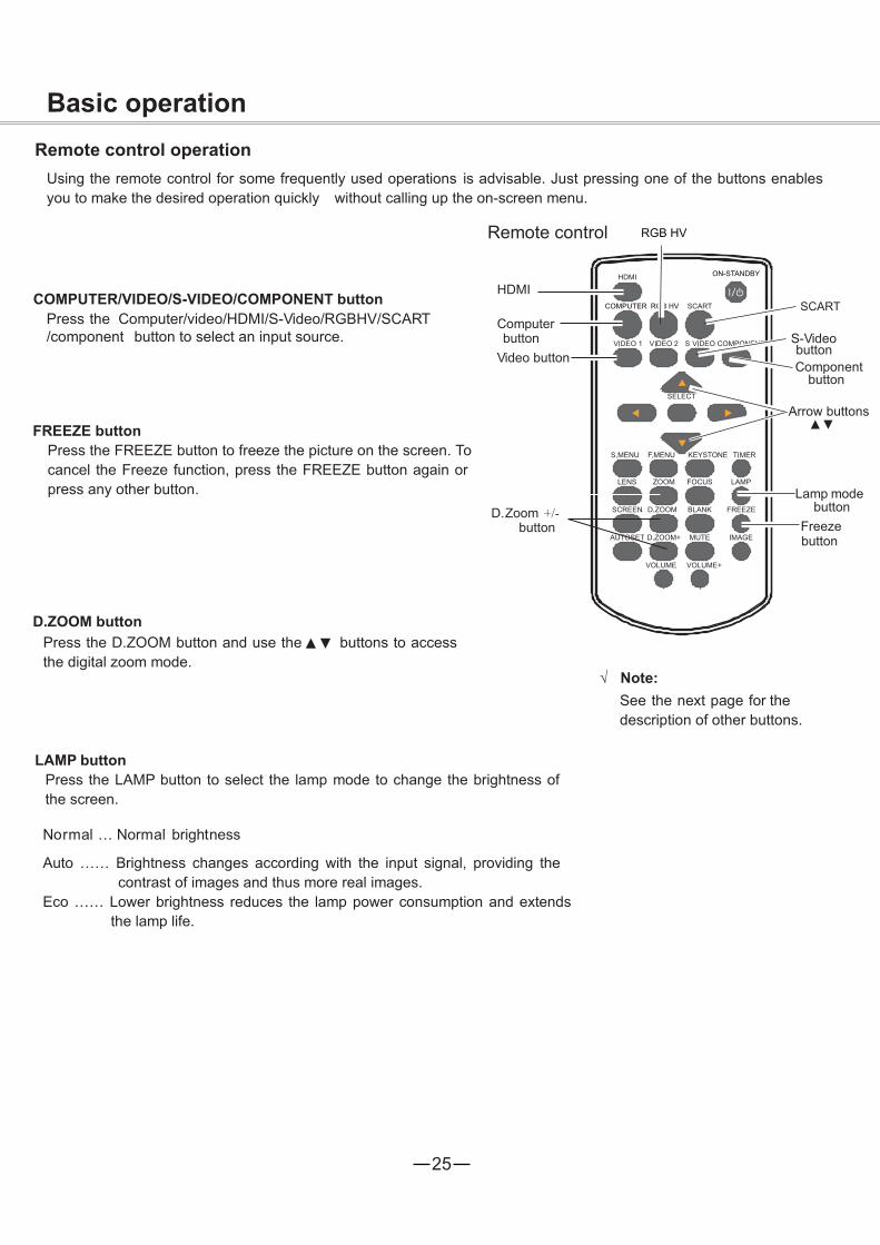
Remote control operationUsing the remote control for some frequently used operations is advisable. Just pressing one of the buttons enablesyou to make the desired operation quickly without calling up the on-screen menu.
Remote control
COMPUTER/VIDEO/S-VIDEO/COMPONENT buttonPress the Computer/video/HDMI/S-Video/RGBHV/SCART/component button to select an input source.
FREEZE button Press the FREEZE button to freeze the picture on the screen. Tocancel the Freeze function, press the FREEZE button again orpress any other button.
D.ZOOM buttonPress the D.ZOOM button and use the buttons to accessthe digital zoom mode.
LAMP buttonPress the LAMP button to select the lamp mode to change the brightness ofthe screen.
Normal … Normal brightness
Auto …… Brightness changes according with the input signal, providing thecontrast of images and thus more real images.
Eco …… Lower brightness reduces the lamp power consumption and extendsthe lamp life.
Note:See the next page for thedescription of other buttons.

26
02 02
Basic operation
LENS buttonZOOM button
Screen modebutton
Timer button
Focus button
Blank button
button
BLANK buttonPress the BLANK button to black out the image. To restore tonormal, press the BLANK button again or press any otherbutton. The screen changes each time you press the button asfollows.Black out Normal Black out Normal...
“Blank” disappears after 4 seconds ifthere is no other button operation.
TIMER buttonPress the TIMER button. The timer display “00:00” appears on thescreen and the timer starts to count time (00:00–59:59).To stop the Timer, press the TIMER button. Press the TIMERbutton again, and then the Timer display disappears.
Timer display
IMAGE buttonPress the IMAGE button on the remote control toselect your required image mode.
SCREEN buttonPress the SCREEN button on the remote control toselect your required screen mode.
LENS buttonPress the LENS button on the remote control to adjust the lensposition.
Note:See the previous page forthe description of otherbuttons.
ZOOM buttonPress the ZOOM button on the remote control to zoom in/out images.
FOCUS buttonPress the FOCUS button on the remote control to adjust the focus of images.
Blank
27
HDMIComputer 1Computer 2
RGBHVSCART
HDMI
VGA 1
VGA 2
RGBHV
SCART
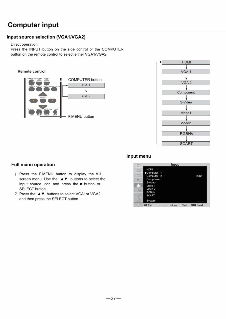
Computer inputInput source selection (VGA1/VGA2)
Direct operationPress the INPUT button on the side control or the COMPUTERbutton on the remote control to select either VGA1/VGA2.
Remote control
Input menu
Full menu operation
Press the F.MENU button to display the fullscreen menu. Use the buttons to select theinput source icon and press the button orSELECT button.Press the buttons to select VGA1or VGA2,and then press the SELECT button.
COMPUTER button
F.MENU button
Component
S-Video
Video1
Video2
Input
ComponentS-videoVideo 1
System
Input
Exit Move
Video 2
Next Next
28
RGBHV
HDMIComputer 1Computer 2
RGBHVSCART
HDMI
VGA 1
VGA 2
RGBHV
SCART
Computer input
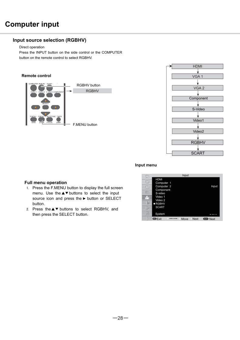
Input source selection (RGBHV)Direct operationPress the INPUT button on the side control or the COMPUTERbutton on the remote control to select RGBHV.
Remote control
Input menu
Full menu operationPress the F.MENU button to display the full screenmenu. Use the buttons to select the inputsource icon and press the button or SELECTbutton.Press the buttons to select RGBHV, andthen press the SELECT button.
RGBHV button
F.MENU button
Component
S-Video
Video1
Video2
Input
System
Exit NextMove
ComponentS-videoVideo 1
Input
Video 2
Next

29
Auto
HDMI
Computer 2
RGBHVSCART
Computer 1
Computer input
Computer system selectionThe projector automatically tunes to various types of computers with its function of Multi-scan system and Auto PCAdjustment. If a computer is selected as a signal source, the projector automatically detects the signal format andtunes to project proper images without any additional setting.
VGA system menuOne of the following messages may appearwhen:The projector cannot recognize the signalbeyond the signal format table, “Auto” isdisplayed on the PC System Menu icon and theAuto PC Adjustment function works to displayproper images. If images are not projectedproperly, adjust manually.
There is no signal input from computer. Checkthe connection between your computer andprojector.
Selecting computer system manually
The system can also be selected manually.
1. Press the F.MENU button to display the full screen menu. Use the buttons to select the input source icon,
and press button or SELECT button.
2. Use the buttons to select System (Signal format), and press button or SELECT button.
3. Press the buttons to select your required system, and then press the SELECT button.
Input
System
Exit Back Move Select
ComponentS-videoVideo 1
Input
The PC system menu displaysthe selected system.
Video 2

30
MENU SELECT
1600
00
01
Computer input
Auto PC adjustment
Auto PC Adjustment function is provided to automatically adjust total dots, horizontal position, vertical position,horizontal image, and vertical image to conform to your computer.
PC adjust menu
Full menu operationAuto PC adjustment
1. Press the F.MENU button to display the full screenmenu. Use the buttons to select the PC adjusticon and press the button or SELECT button.
2. Press the buttons to select AUTO PCAdjustment, and then press the SELECT button.
To store the adjusted parametersThe system parameters adjusted in the Auto PC Adjustment can be stored in the projector.
Note:Total dots and horizontal & vertical positions of some computers cannot be fully adjusted with this Auto PCAdjustment function. When the image is not provided properly with this operation, manual adjustments arerequired.The Auto PC Adjustment cannot be operated when 480i, 575i, 480p, 575p, 720p, 1035i,or 1080i is selected in the PC System Menu
PC adjustAuto PC adj.Fine syncTotal dotsHorizontalVerticalClampDi s pla y area HDi s pla y area VResetMode freeStore
Exit Move NextNext

31
Computer inputManual adjustment via PC
As some PCs adopt special signal formats, the multi-purpose scanner of may not detect them. To match thespecial-format signals, offers function of manual adjustment, with which users can adjust the parameters.provides 5 independent memory sections, where the manually adjusted parameters can be saved. In the caseof specific PC, the user can make use of the memory space to set up whenever necessary.
1. Press F. Menu to display the F. Menu. Press toselect the icon for PC adjustment. Then press orpress Select.
2. Press to select the item to be adjusted, andthen press Select. At the time, the adjustmentdialogue box will appear. Press to set the value.
Fine sync:Use it to eliminate the flashing of the image. Pressto adjust the value.
Total dots:Press to adjust the total dots for a cycle so that it can match the image on PC.
Horizontal:Press to adjust the horizontal position of the image.
Vertical :Press to adjust the vertical position of the image.
Clamp:Press to adjust the clamp position. When black strips appear on the image, you can use this function.
D i s p l ay area H:Press to adjust the area of horizontal projection.
D i s p l ay area V:Press to adjust the area of vertical projection.
Reset:To re-set the adjusted data, you should select the initial state, and then press Select. Click Yes when the dialogue boxappears for confirmation. After that, all adjusted value will return to the initial state.
Mode free:To delete the saved data, you should select the Standby Mode, and press or Select. The mode to be deleted will behighlighted. At the time, click Select.
Store:To save the adjusted data, you should select Save, and press or Select. Then move the cursor to select the savingmode from the items 1-5. Finally click Select.
Note:If you select 480i, 575i, 480p, 575p, 720p, 1035i or 1080i from the system menu, the functions of both horizontalimage and vertical image will be disabled.
PC adjust menu
MENU SELECT
1600
00
01
PC adjustAuto PC adj.Fine syncTotal dotsHorizontalVerticalClampDi s pla y area HDi s pla y area VResetMode freeStore
Exit Move NextNext

32
MENU SELECT
Computer input
Selecting image modeDirect selection:
Use the key Image on the remote control to select theimage mode.
Operation through F. Menu1. Press F. Menu to display the F. Menu. Press to
select the icon for Image select . Then press orpress Select.
2. Press to select the desired item, and then pressSelect.
When the image is viewed in a room, select this mode.
This is the default image mode.
Multiple grey scales can be selected, and it suits forwatching movies.
This mode can be used to project the image on a greenboard to enhance the image quality. It mainly functionson a green board, not black board.
This mode is suitable for projecting the image onto thered, blue, yellow or green wallpaper.
This is the image mode pre-set by in the imageadjustment menu.
Remote control
Key for selecting an image mode
Menu for selecting image qualityImage select
DynamicNormalCinemaBlackboard(Green)
RedUser Image
Move NextExit Next
Colorboard
Dynamic
Normal
Cinema
Blackboard(Green)
User Image
Colorboard

33
32
MENU SELECT
32
32 32
32
8
8
Computer input
Adjusting image
1. Press F. Menu on the remote control to display the on-screenmenu. Press to select the icon for image adjustment.Then press or press Select.
2. Press to select the item to be adjusted, and then pressSelect. At the time, the adjustment dialogue box will appear.Press to set the value.
ContrastPress to decrease the contrast and press to increase it.
BrightnessPress to decrease the brightness and press to increase it.
Color temp.Press to select the desired color temperature (option are“ High ”,“Mid ” and “ low”)
RedPress to make the red color lighter and press to make it stronger.
GreenPress to make the green color lighter and press to make it stronger.
BluePress to make the blue color lighter and press to make it stronger.
SharpnessPress to soften the image and press to sharpen it.
GammaPress to adjust the grey level to achieve better contrast and balance.
Note:After white balance (red), white balance (green) or white
balance (blue) is adjusted, the color temperature will change to“User”.
When Blackborad (Green) or colorboard is selected in the“ Imageselect ”, the color temperature will change to “Blackboard ”or “ colorboard”
Menu for adjusting imageImage adjust
ContrastBrightnessColor temp.RedGreenBlueSharpnessGamma
Move NextExit Next
Mid
34
MENU SELECT
Computer input
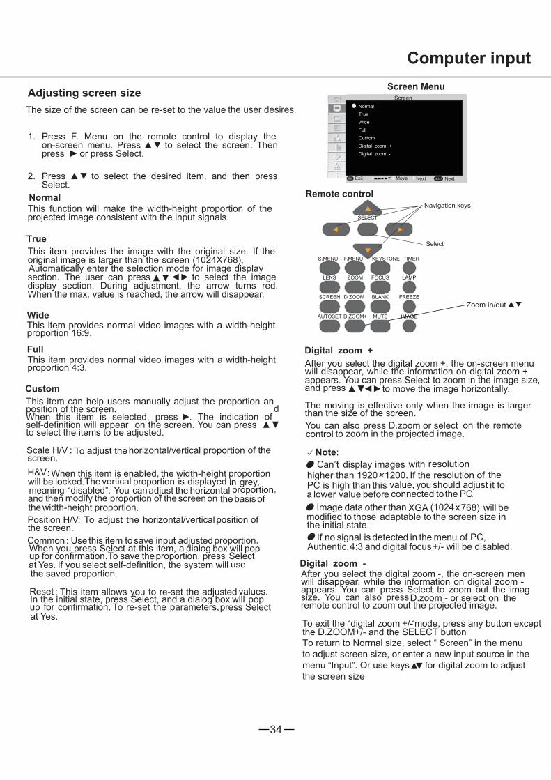
Adjusting screen sizeThe size of the screen can be re-set to the value the user desires.
1. Press F. Menu on the remote control to display theon-screen menu. Press to select the screen. Thenpress or press Select.
2. Press to select the desired item, and then pressSelect.
This function will make the width-height proportion of theprojected image consistent with the input signals.
This item provides the image with the original size. If theoriginal image is larger than the screen (1024X768),Automatically enter the selection mode for image displaysection. The user can press to select the imagedisplay section. During adjustment, the arrow turns red.When the max. value is reached, the arrow will disappear.
This item provides normal video images with a width-heightproportion 16:9.
This item provides normal video images with a width-heightproportion 4:3.
This item can help users manually adjust the proportion andposition of the screen.
When this item is selected, press . The indication ofself-definition will appear on the screen. You can pressto select the items to be adjusted.
Screen MenuScreen
NormalTrue
Digital zoom +
Move NextExit
Navigation keys
Select
Zoom in/out
Remote control
Next
Digital zoom -
CustomFullWide
Normal
True
Custom
Full
Wide
Scale H/V : To adjust the horizontal/vertical proportion of thescreen.H&V: When this item is enabled, the width-height proportionwill be locked.The vertical proportion is displayed in grey,meaning “disabled”. You canadjust the horizontal proportion,and then modify the proportion of the screenon the basis ofthe width-height proportion.Position H/V: To adjust the horizontal/vertical position ofthe screen.Common: Use this item tosave input adjusted proportion.When you press Select at this item, a dialog box will popup for confirmation.To save theproportion, press Selectat Yes. If you select self-definition, the system will usethe saved proportion.
Reset : This item allows you to re-set the adjusted values.In the initial state, press Select, and a dialog box will popup for confirmation. To re-set the parameters,press Selectat Yes.
After you select the digital zoom +, the on-screen menuwill disappear, while the information on digital zoom +appears. You can press Select to zoom in the image size,and press to move the image horizontally.
The moving is effective only when the image is largerthan the size of the screen.You can also press D.zoom or select on the remotecontrol to zoom in the projected image.
Digital zoom +
After you select the digital zoom -, the on-screen menwill disappear, while the information on digital zoom -appears. You can press Select to zoom out the imagsize. You can also press on theremote control to zoom out the projected image.
To exit the “digital zoom +/-“mode, press any button exceptthe D.ZOOM+/- and the SELECT buttonTo return to Normal size, select “ Screen” in the menuto adjust screen size, or enter a new input source in themenu “Input”. Or use keys for digital zoom to adjustthe screen size
Note:Can’t display images with resolution
higher than 1920× 1200. If the resolution of thePC is high than this value, you should adjust it toa lower value before connected tothe PC.
Image data other than XGA (1024x768) will bemodified to those adaptable to the screen size inthe initial state.
If no signal is detected in the menu of PC,Authentic,4:3 and digital focus+/- will be disabled.
Digital zoom -
D.zoom - or select

35
HDMIComputer 1Computer 2
RGBHVSCART
MENU SELECT
AV Input
Selecting input source (video, S-video, Component, SCART, HDMI)
Direct selectionPress the input key on the control panel at the side , or press Video, S-video, Component,SCART, HDMI on the remote control, to select video, S-video and Component.
Operation through menu
1. Press F. Menu on the remote control to display theF. Menu. Press to select the icon forinput source. Then press or press Select.
2. Press to select“ video” or “ S-video ”, and then press Select.
ComponentSelect “Component” if the input source is a videodevice connected to Y, Cb/Pb and Cr/Pr through thecomponent VGA cable.
VideoSelect Video when input video signal is connected toVIDEO terminal.
S-videoSelect S-video when input video signal isconnected to the S-video.
SCARTSelect “SCART” if the input source is a video deviceconnected to SCART IN/COMPUTER IN through theSCART VGA cable.
HDMIConnect to HDMI when the video signal is connectedto HDMI terminal.
Remote control
Video
Component
Input menu
ComponentS-videoVideo 1Video 2
MoveExitSystem
Input
S-VIDEO
Next Next
Input

36
HDMI
RGBHVSCART
MENU SELECT
AV InputSelecting AV system
1. Press F. Menu on the remote control to displaythe on-screen menu. Press to select theicon for input source. Then press or pressSelect.
2. Press to select “ Component ”, “ video ”or “ S-video ” , and then press Select.
3. Press to select the system, and then pressor press Select. Press to select the
signal format, then press Select.
Video or S-video.
AutoCan automatically detect the input videosystem and optimize its own state. If the videosystem is PAL-M or PAL-N, you should manuallyselect the system.
PAL/SECAM/NTSC/NTSC4.43/PAL-M/PAL-NIf can’t reproduce the image, you shouldselect a specific signal format from PAL, SECAM,NTSC, NTSC 4.43, PAL-M and PAL-N.
Component
AutoCan automatically detect the input videosystem and optimize its own state.
Component video signal formatIf can’t reproduce the image, you shouldselect a specific component video signal formatfrom 480i, 575i, 480p, 575p, 720p, 1035i and 1080i.
Note:If SCART or HDMI is selected, AV system menu
will be disabled.
AV System Menu (AV or S-video)Input
Component
Video 1Video 2
Move SelectExit Back
System
Input
AV System Menu (Component)
SECAM
HDMIComputer 1Computer 2
RGBHVSCART
MENU SELECT
Input
ComponentS-videoVideo 1Video 2
Move SelectExit Back
System
Input
575p
Computer 1Computer 2
S-video

37
MENU SELECT
Selecting image mode
Direct selection:Use the key Image on the remote control to selectthe image mode.
Menu selection1. Press F. Menu to display the F. Menu. Press
to select the icon for image select. Thenpress or press Select.
2. Press to select the desired item, and thenpress Select.
DynamicWhen the image is viewed in a room, select thismode.
This is the default image mode.
Improved half-tone lifelike image mode.
Blackboard(Green)This mode can be used to project the image on agreen board to enhance the image quality. It mainlyfunctions on a green board, not black board.
ColorboardThis mode is suitable for projecting the image ontothe red, blue, yellow or green wallpaper.
This is the image mode pre-set by in the imageadjustment menu.
Remote control
Key for selecting an image mode
Menu for selecting image quality
Image select
Dynamic
Normal
CinemaBlackboard(Green)
edRboardroloC
User Image
Move NextExit
AV Input
Next
Normal
Cinema
User Image
38
32
MENU SELECT
32
32
On
32 32
32
32
8
8
L1
AV Input
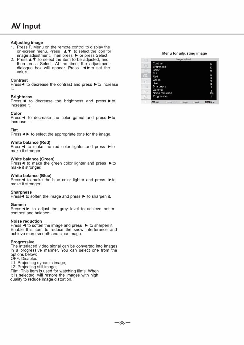
Adjusting image1. Press F. Menu on the remote control to display the
on-screen menu. Press to select the icon forimage adjustment. Then press or press Select.
2. Press to select the item to be adjusted, andthen press Select. At the time, the adjustmentdialogue box will appear. Press to set thevalue.
ContrastPress to decrease the contrast and press to increaseit.
BrightnessPress to decrease the brightness and press toincrease it.
ColorPress to decrease the color gamut and press toincrease it.
TintPress to select the appropriate tone for the image.
White balance (Red)Press to make the red color lighter and press tomake it stronger.
White balance (Green)Press to make the green color lighter and press tomake it stronger.
White balance (Blue) Press to make the blue color lighter and press tomake it stronger.
SharpnessPress to soften the image and press to sharpen it.
GammaPress to adjust the grey level to achieve bettercontrast and balance.
Noise reductionPress to soften the image and press to sharpen it.Enable this item to reduce the snow interference andachieve more smooth and clear image.
ProgressiveThe interlaced video signal can be converted into imagesin a progressive manner. You can select one from theoptions below:OFF: Disabled;L1: Projecting dynamic image;L2: Projecting still image;Film: This item is used for watching films. Whenit is selected, will restore the images with high
Menu for adjusting imageImage adjust
ContrastBrightnessColorTintRedGreenBlueSharpnessGammaNoise reductionProgressive
Move NextExit Next
quality to reduce image distortion.

39
MENU SELECT
Adjusting screen size
The size of the screen can be re-set to the value the user desires.
1.Press F. Menu on the remote control to display the on-screen menu.
NormalThis function will make the width-height proportion of the projected image consistent with the input signals.
WideThis item provides normal video images with a width-height proportion 16:9.
Note:
automatically set as normal state. At the
adjusted according to the input signal.
NormalWideCustom
Move
Screen Menu
AV Input
CustomThis item can help users manually adjust the proportion and position of the screen.
The indication of self-definitionwill appear on the screen. Yto be adjusted.
T oportion of the screen.
width-height proportion will be locked. The vertical proportion is displayed in grey “disabled”.You can adjust thehorizontal proport then modify the proportion of the screen on the basis of the width-heightproportion.
T vertical position of the screen.
Common: Use this item to save input adjusted proportion. WhenT
Y
Reset:T
Yes.

40
2/2
MENU SELECT
1/2
MENU SELECT
menu
Setting
On startStandby modeClosed captionLamp controlTest pattern
High landCooling fast
Filter counterWarning logFactory default
Off
MoveExit Next
LanguageOSD settingAuto setupKeystoneBlue BackDisplayLogoCeilingRearTerminalPower management
English
MoveExit Next
menu
Setting
Setting
Setting
You can use Setting menu to configure thefollowing functions.
1. Press F. Menu on the remote control to display theon-screen menu. Press to select Setting.Then press or press Select to enter thesubmenu.
2. Press to select the desired item to beadjusted, and then press or press Select toreach the selected item.
3. Press to select the desired item and thenpress Select.
OSD languageOSD languages include English, Chinese, German,French, Italian, Portugal, Dutch, Romanian, Spanish,Polish, Finnish, Russian, Hungarian, Thai, Swedish,Korean and Japanese.
OSD settingPress to select menu setting. then press Select or .
Menu position:You can use this function to change the position ofon-screen menu. To do that, select menu setup,and press Select. Each time you press Select,the menu’s position on the screen in the orderbelow:Upper left Upper right Center Lower leftLower right Upper left …
TranslucentThis item allows you to change the transparency ofthe on-screen menu. Press to select from theseoptions: Off, High, Mid and Low.
BackgroundThis item allows you to change the background of theon-screen menu. Press to select from options1-6.
SecurityOff
Off
OffEco
Off
StoreOnOn
AutoOff
Monitor out
Back
Back

41
Blue backYou can use this item to set the background ofThe time when no signal is detected.You can press to switch over between theitems below:ON: To enable the blue background forprojection;OFF: To disable the blue background.
SettingAuto setup
Input searchThis function detects the input signal automatically. When a signal is found, the search will stop. Use the Pointbuttons to select one of the following options.Off ........... Input search will not work.On.............Active Input Sourcing fuction. It detects the
input signal and search stops when the signal is found.
Auto PC AdjustmentOn.............Press Auto Set button on the Top Control or
remote control to enable Auto PC Adjustmentfunction.
Off ........... Disables Auto PC Adjustment.
This function enables Input search, by pressing the
and Auto PC adjustment by AUTO SETUP button on the top control or the
AUTO SET button on the remote can be altered as follo
control. Settings for thosews:
Keystone CorrectionThis function is used to store or reset the keystone correction when the AC power cord is unplugged. Use the Point buttons to switch between each option.
Store ...... ...... Keep the keystone correction even when the AC power cord is unplugged.
Reset ............ Release the keystone correction when theAC power cord is unplugged.
To correct keystone distortion, press the SELECT button. Keystone appears on the screen. Use the Point buttons to correct keystone distortion.
NOTE:Only the last selected input source can be detected.If the INPUT button on the top control or the COMPUTER 1/2 buttons, VIDEO or S-video or COMPONENT buttons on the remote control is pressed during Input search is in progress, Input search will stop and go back to the previous input signal.Input Search, Auto PC Adj. and can not be set Off at the same time.
Fine sync., Total dots, Horizontal and Vertical position of some computers cannot be fully adjusted with the Auto PC Adjustment function. When the image is not provided properly with this operation, manual adjustments are required.

42
Setting
Logo (Logo and Logo PIN code lock settings)This function allows you to customize the screen logo with Logo select, Capture, Logo PIN code lockand Logo PIN code change functions.
NOTE:When On is selected in the Logo PIN code lock function, Logo select and Capture functions cannot be
selected.
Logo selectThis function decides on the starting-up displayfrom among following options.
User ........ Show the image you captured.Default .... Show the factory-set logo.Off ........... Show the countdown display only.
Capture
This function enables you to capture an image being projected to use it for a starting-up display or interval of presentations.
Select Capture and press the SELECT button. A confirmation box appears and select Yes to capture the projected image.
After capturing the projected image, go to the Logo select function and set it to User. Then the captured image will be displayed the next time you turn on the projector.
This function prevents an unauthorized person from changing the screen logo.
Off ...........The screen logo can be changed freely from the Logo Menu.On ...........The screen logo cannot be changed without a Logo PIN code.
If you want to change the Logo PIN code lock setting, press the SELECT button and the Logo PIN code dialog box appears. Enter a Logo PIN code by following the steps below.
Logo PIN code lock
On............................ Show startup screen
Off............................ Show the input image instead of the on-start screen
Display
You can use this item to set whether the startup animation is displayed.
43
SettingLogo PIN code lockUse the Point buttons to enter a number. Press the Point button to fix the number and move the redframe pointer to the next box. The number changes to “*”. If you fixed an incorrect number, use the Pointbutton to move the pointer to the number you want to correct, and then enter the correct number.
Repeat this step to complete entering a three-digit number.
After entering the three-digit number, move the pointer to Set. Press the SELECT button so that you can start to operate the projector.
If you entered an incorrect Logo PIN code, Logo PIN code and the number (***) will turn red for a moment. Enter the correct Logo PIN code all over again.
Logo PIN code can be changed to your desired three-digit number. Press the SELECT button to select LogoPIN code change. Logo Pin code dialog box appears, use the Point buttons to enter the correct code. TheNew Logo PIN code input dialog box appears. Set a newLogo PIN code, confirmation box appears, choose yes to set the new Logo Pin code.
Be sure to note the new Logo PIN code and keep it on hand. If you lost the number, you could no longer change the Logo PIN code setting.
Use the Point buttons to switch On or Off, and then press the SELECT button to make a choice.
Change the Logo PIN code lock setting
CAUTION:WHEN YOU HAVE CHANGED THE LOGO PIN CODE,WRITE DOWN THE NEW PIN CODE IN COLUMN OF THE LOGO PIN CODE NO. MEMO ON PAGE 59, ANDKEEP IT SECURELY. SHOULD THE LOGO PIN CODEBE LOST OR FORGOTTEN, THE LOGO PIN CODESETTING CAN NO LONGER BE CHANGED.
Logo PIN code change

44
Setting
Rear
When this function is set to On, the picture will be left/right reversed. This function is used to project the image from rear of the screen.
Terminal
The COMPUTER IN 2/MONITOR OUT terminal on the back of the projector is switchable for computer input or monitor output. (See page 9) Select Computer or Monitor Out with the Point buttons.
PC 2 ................. ...Computer 2 Inputomputer 2 InputMonitor Output...Monitor Output
Power management
Time left before Lamp is off.
Power management
For reducing power consumption as well as maintaining the lamp life, the Power management function turns offthe projection lamp when the projector is not operated for a certain period.
Select one of the following options:Ready .................. When the lamp has been fully cooled down, the POWER indicator changes to green blinking.
In this condition, the projection lamp will be turned on if the input signal is reconnected or any button on the top control or remote control is pressed.
Shut down .......... When the lamp has been fully cooled down, the power will be turned off.Off ....................... Power management function is off.Timer ................... If the input signal is interrupted and no button is pressed for more than 30 seconds, the timer
display with No signal appears. It starts the countdown until the lamp is turned off. Use the Point buttons to set the Timer(1~30min.).
NOTE: Factory default is Ready: 5 Min.
On startThis function enables projector auto power on with detection connection with AC power cord.
CeilingThis function is used to project the image from a ceiling-mounted projector.Off ......Disable this function.Auto ........The picuture will be top/bottom and left/right reversed automatically.On..........The picture will be top/bottom and left/right reversed.
Rear
No signal01 : 20

45
Setting
Auto............Brightness is adjusted according to the input signal.
Standby modeThis function is available when operating the projector via network.
Normal ...... Supply the power to the network function even after turning off the projector. You can turn on/ off the projector via network, modify network environment, and receive an e-mail about projector status while the projector is powered off. Eco ........... Select Eco when you do not use the projector via network. The projector’s network function will stop when turning off the projector.
Closed Caption
Closed Caption is a text version of the program sound or other information displayed on the screen.If the input signal contains closed captions, you can turn on the feature and switch the channels. Press the Point buttons to select Off, CC1, CC2, CC3 or CC4.If the closed caption is not clear, you can change the text from Color to white.
NOTE:The Closed Caption is available only under the situation below.
set on Auto.The system must be set on NTSC or Auto in Video System Selection. (P.36)The icon of Closed Caption is displayed in gray while it is not available.The Closed caption is unavailable when On-Screen menu and Timer are displayed.
This function allows you to change brightness of the screen.
Normal ...... Normal brightnessEco ............Lower brightness reduces the lamp power consumption and extends the lamp life.
Lamp Control
Key lock
Security (Key lock and PIN code lock)
This function locks the top control and remote control buttons to prevent operation by unauthorized persons. Select Key lock and then press the SELECT button, and select the desired item by pressing the Pointbuttons.
Off.................. Unlocked.
Projector ........ Lock the operation of the top control. To unlock, use the remote control.
Remote Control ..... Lock the operation of the remote control. To unlock, use the top control.
If the top control accidentally becomes locked and you do not have the remote control nearby or there is something wrong with your remote control, contact the dealer where you purchased the projector or the service center.
This function allows you to use the Key lock and PIN code lock function to set the security for the projector operation.
This function enables you to test & set interior signals.Test Pattern
46
Setting
PIN code lockThis function prevents the projector from being operated by unauthorized persons and provides the following setting options for security.
Off ............ Unlocked.On ........... Enter the PIN code every time turning on the projector.
Whenever you change the PIN code lock setting or the PIN code (the three-digit number), you are required to enter the PIN code. The “111” is set as the initial PIN code at the factory.
If you want to change the PIN code lock setting, Press the SELECT button and the PIN code dialog box appears.
Enter a PIN codeUse the Point buttons to enter a number. Press the Point button to fix the number and move the redframe pointer to the next box. The number changes to “*”. If you fixed an incorrect number, use the Pointbutton to move the pointer to the number you want to correct, and then enter the correct number.
Repeat this step to complete entering a three-digit number.
After entering the three-digit number, move the pointer to “Set.” Press the SELECT button so that you can start to operate the projector.
If you entered an incorrect PIN code, PIN code and the number (***) will turn red for a moment. Enter the correct PIN code all over again.
Use the Point buttons to select Off or On, and then press the SELECT button to make a choice.Change the PIN code lock setting
The PIN code can be changed to your desired three-digit number. Press SELECT button to select PIN code change. Pin code dialog box appears, use the Point buttons to enter the correct code. The New PIN code input dialog box appears. Set a new PIN code.
CAUTION:WHEN YOU HAVE CHANGED THE PIN CODE, WRITE DOWN THE NEW PIN CODE IN COLUMN OF THE PIN CODE NO. MEMO ON PAGE 59, AND KEEP IT SECURELY. IF YOU FORGET YOUR PIN CODE, THE PROJECTOR CAN NO LONGER BE STARTED.
PIN code change

47
Setting
ON (1)........The fan runs faster than normal speed. When operated in places with high altitude(2000m), the cooling fan will produce weaker effects. So, you should select this item.
ON (2)........The fan runs faster than “ON (1)”. When operated in places with high altitude(above 3000m), the cooling fan will produce weaker effects. So, you should select this item.
There are the following options in the cooling fans operation when the projector is turned off. ON ... Faster and louder-sound than the normal operation, but it takes less time to cool the projector down. OFF ... Normal operation.
Cooling fast
This projector provides Fan control function in the "Setting" menu. Choose the running speed of cooling fans from the following options according to the ground elevation where you use the projector.Off......Normal speed.Set this function to "Off" when using the projector in non-high altitude environment.
High land
This function is used to set a frequency for the filter cleaning.
When the projector reached a specified time between cleanings, a Filter warning icon appears on the screen, notifying the cleaning is necessary. After cleaning the filter, be sure to select RESET and set the timer. The Filter warning icon will not turn off until the filter counter is reset.
Filter counter
Factory defaultThis function returns all setting values except for the User logo, PIN code lock, Logo PIN code lock,Lamp counter and Filter counter to the factory default settings.

48
KH
H
MENU SELECT
z
z
1080i
A
Information
Displaying input source
The information menu is used to detect signal of projected image and running state
Operation through menu
Press to select the information. And the information menu will appear.You can then see the information displayed as follows:
Information
Input
H-sync freq.V-sync freq.ScreenLanguageLamp status
Power management
Key lock
BackExit Move
Component
NormalEnglish
10 H Off1 min
Lamp counter
H-sync freq .
V-sync freq .
Lamp counter
The horizontal frequency of the input signal is displayed inKHz, or - - - -KHz when no signal.
The vertical frequency of the input signal is displayed in Hz,or - - - - Hz when no signal. Numbers of Hz doubles whenduring Interlace.
The cumulative lamp operating time is displayed.
Press Input on the Top Control and then press SELECTbutton to display on screen menu. Press the Point buttons to select the Information. The Information Menu is displayed.
See below for displayed information.
Menu Operation
Input
Language
The selected input source is displayed.
The selected language is displayed.
Key lockDisplay Off, Remote Control or the Projector.
Power management
ScreenThe selected screen size is displayed.
Lamp statusThe selected lamp mode is displayed.
Off, Ready or Shut down is displayed.
49
“Warning Temper” indicator
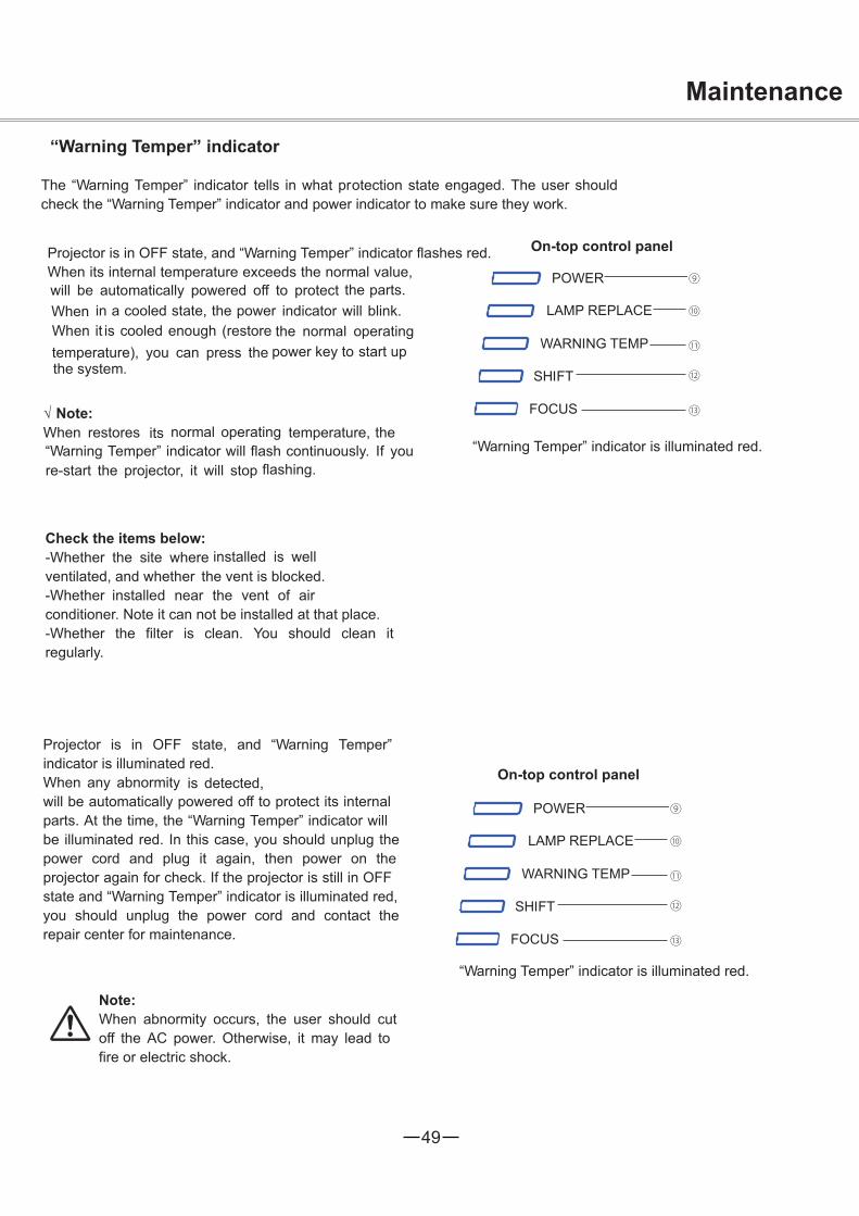
The “Warning Temper” indicator tells in what protection state engaged. The user shouldcheck the “Warning Temper” indicator and power indicator to make sure they work.
Projector is in OFF state, and “Warning Temper” indicator flashes red.When its internal temperature exceeds the normal value,will be automatically powered off to protect the parts.When in a cooled state, the power indicator will blink.When it is cooled enough (restore the normal operatingtemperature), you can press the power key to start up the system.
Note:When restores its normal operating temperature, the“Warning Temper” indicator will flash continuously. If youre-start the projector, it will stop flashing.
Check the items below:-Whether the site where installed is wellventilated, and whether the vent is blocked.-Whether installed near the vent of airconditioner. Note it can not be installed at that place.-Whether the filter is clean. You should clean itregularly.
Projector is in OFF state, and “Warning Temper”indicator is illuminated red.When any abnormity is detected,will be automatically powered off to protect its internalparts. At the time, the “Warning Temper” indicator willbe illuminated red. In this case, you should unplug thepower cord and plug it again, then power on theprojector again for check. If the projector is still in OFFstate and “Warning Temper” indicator is illuminated red,you should unplug the power cord and contact therepair center for maintenance.
On-top control panel
“Warning Temper” indicator is illuminated red.
Note:When abnormity occurs, the user should cutoff the AC power. Otherwise, it may lead tofire or electric shock.
On-top control panel
“Warning Temper” indicator is illuminated red.
Maintenance

50
Note:Keep from dust and smog.Otherwise, the image quality may deteriorate.When operated in an environmentwith dust and smog, the dust and dirt willaccumulate on its lens, liquid crystal board orthe lens assembly inside the projector. If thathappens, you should contact the localdistributor or repair center for correctcleaning.
MaintenanceCleaning the filter
The filter prevents dust from accumulating on the surface of lens assembly. Should thefilter become clogged with dust particles, it will reduce the cooling fan’s effectiveness and may resultin internal heat buildup and adversely affect the life of the projector. If a Filer warning icon appears onthe screen, you should clean the filter immediately. To do that, follow the steps below:
1. Turn off the projector, and unplug the AC powercord from the outlet.
2. Remove the air filter from the projector.3. Brush the filter clean.4. Install the filter onto the projector again and make
sure it is secured properly.
Note:Do not operate the projector when thefilter is removed. Otherwise, dust will beaccumulated on lens and thus affect theimage quality.Never attempt to place any objects to theair intake vents. Otherwise, the projectormay malfunction.
Filter
Resetting the filter counter
1. Press F. Menu on the remote control to display theF. Menu. Press to select the icon for thesetting menu. Then press or press Select.
2. Press to select Filter counter , and then pressor press Select. Press to select Reset Filter,
then press Select. At the time, you will see theprompt information “Reset the filter counter ?”displayedon the screen. Select Yes.
3. When another dialog box pops up, you shouldselect Yes and reset the filter.
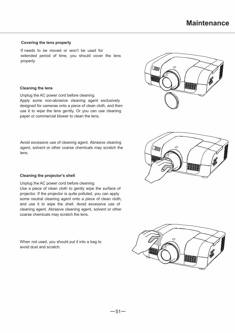
51
Maintenance
Covering the lens properly
If needs to be moved or won’t be used forextended period of time, you should cover the lensproperly.
Cleaning the lens
Unplug the AC power cord before cleaning.Apply some non-abrasive cleaning agent exclusivelydesigned for cameras onto a piece of clean cloth, and thenuse it to wipe the lens gently. Or you can use cleaningpaper or commercial blower to clean the lens.
Avoid excessive use of cleaning agent. Abrasive cleaningagent, solvent or other coarse chemicals may scratch thelens.
Cleaning the projector’s shell
Unplug the AC power cord before cleaning.Use a piece of clean cloth to gently wipe the surface ofprojector. If the projector is quite polluted, you can applysome neutral cleaning agent onto a piece of clean cloth,and use it to wipe the shell. Avoid excessive use ofcleaning agent. Abrasive cleaning agent, solvent or othercoarse chemicals may scratch the lens.
When not used, you should put it into a bag toavoid dust and scratch.

52
To replace the lamp, follow the steps below:1. Power off the projector and unplug the power
cord. Then let the project cool for at least 45minutes.
2. Loosen the screws on the lamp cover and openthe cover.
3. Make sure the lamp is well protected andremove two screws. Hold the handle and pullout the lamp.
4. Install a new lamp with the same model andtighten the two screws. Make sure theinstallation is correct. Put lamp cover in placeand then tighten the screws.
5. Plug the AC power cord and power on theprojector.
Screw
Handle
Lamp
Screw
ScrewLampcover
Note:When the lamp isn’t illuminated, it may indicate that the lamp has been damaged.When you replace the lamp in a projector installed on the ceiling, you should stand beside the lampcover but not under it; for the broken glass may fall down to hurt you. To do that, remove the lampcover gently to avoid being hurt by the dropped glass. If glass drops into your eyes or mouth, youshould see the doctor immediately.
Note: Note:
As temperature inside the projector is high, youshould cool the projector for at least 45 minutesbefore you open the lamp cover.
For the sake of safety, only use the lamp of thesame model. Never drop the lamp onto the groundnor touch the glass bulb! The glass can shatter andhurt.
MaintenanceReplacing the lampWhen the service life of the projection lamp is over, theicon suggests that the lamp needed to be replaced willappear on the screen, and the indicator for thereplacement will flash yellow. If so, you shouldimmediately replace it with a new one of the same model.The flashing time of the replacement indicator is subjectto the lamp mode.

53
Maintenance
Changing the lamp model
Purchasing new lampsUsers can buy new lamps through the local distributor. Your purchase order should include theinformation below:
Lamp model
This projector uses a high-pressure lamp which must be handled carefully and properly.Improper handling may result in accidents, injury, or create a fire hazard.
Lamp life may differ from lamp to lamp and according to the environment of use. There is no guaranteeof the same life for each lamp. Some lamps may fail or terminate their life in a shorter period of time than other similar lamps.
If the projector indicates that the lamp should be replaced, i.e., if the LAMP REPLACE indicator lightsup, replace the lamp with a new one IMMEDIATELY after the projector has cooled down.
(Follow carefully the instructions in the Lamp Replacement section of this manual.) Continuous use of the lamp with the LAMP REPLACE indicator lighted may increase the risk of lamp explosion.
A Lamp may explode as a result of vibration, shock or degradation as a result of hours of use as itslifetime draws to an end. Risk of explosion may differ according to the environment or conditions in which the projector and lamp are being used.
IF A LAMP EXPLODES, THE FOLLOWING SAFETY PRECAUTIONS SHOULD BE TAKEN .
If a lamp explodes, disconnect the projector’s AC plug from the AC outlet immediately. Contact an authorized service station for a checkup of the unit and replacement of the lamp. Additionally, check carefully to ensure that there are no broken shards or pieces of glass around the projector or coming out from the cooling air circulation holes. Any broken shards found should be cleaned up carefully. No one should check the inside of the projector except those who are authorized trained technicians and who are familiar with projector service. Inappropriate attempts to service the unit by anyone, especially those who are not appropriately trained to do so, may result in an accident or injury caused by pieces of broken glass.
LAMP HANDLING PRECAUTIONS

54
Appendix
Troubleshooting
Before you contact the local distributor or repair center, you may check the items below once again.
-Make sure you have properly connected to the peripheral equipment.-Make sure all equipment has been connected to AC power source and the power source is in ON state.-If it can’t project image output from a PC, please re-start the PC.
noituloSeruliaF
Machine can’t be powered on -Plug the power cord of the projector into the AC power outlet.-Check whether the power indicator turns red.-Only when the power indicator turns red can you power on theprojector again.-Check the Warning Temp indicator. If it is illuminated red, you can’tpower-Check the projection lamp.-Unlock the “key lock” function.
No initial displaying -Make sure both displa ying and count-down functions are enabled.
Initial displaying is inconsistentwith factory defaults
-Make sure the item User or OFF is not selected in the startupanimation.
Input signals are automatically switched(can’t be switched)
-Adjust the search function of input source properly.
When input is pressed during startup, anon-Lamp icon appears.
-This icon warns that the filter needs to be replaced.
An icon of non-input mode or lamp modeappears
-This icon indicates the replacement of lamp or warns for the filter.
Ambiguous images -Adjust the focus-Set a more proper projection distance.-Check whether the lens needs to be cleaned.-When moved from a environment with low temperature tothe one with higher temperature, water will be condensed on the lens. Ifso, you have to wait till the condensed water disappears.
Image turns over leftward/rightwardImage turns over upward/downward
-Check the function of “ceiling/rear”.-Check the function of “ceiling”.
Image not bright enough -Check whether the contrast or brightness is adjusted correctly.-Check whether the image mode is properly selected.-Check the function of lamp brightness adjusting.-Check the lamp and replace the indicator. If the indicator is illuminated,it means the service life of the lamp is over. You should replace the lampwith a new one of the same model immediately.
55
Appendix
No image -Check the connection between PC or video equipment-Check with the signal from PC is correct. If connected tocertain laptops, the settings of their video adapters need to be changed.You can refer to the operating instructions of the PC for suchmodification.-Images can show up only about 10 seconds after the projector ispowered on.-Check the input signal, color system,video system or PC system mode.-Make sure that the temperature doesn’t exceed the permitted operatingtemperature (41F–95 F [5C–35C]).-If non-displaying function is enabled, no image will appear on thescreen. You can then press the non-display key or other keys.
No sound is heard. -Check that the audio cable from the input source is correctly connected.-Adjust the audio source.-Press the key “+”.-Press the key “Mute”.-If the audio cable is inserted into the port AUDIO OUT, the internalspeaker of the projector will be disconnected.-Is there any image projected? Only when the image appears on thescreen, can the sound be heard.
Abnormal color -Check the input signal, color system, video system or PC system mode.-Make sure the green board is not selected in the item “image quality”.
Some information can’t be seen in theoperation.
-Check the function of displaying.
Automatic adjustment through PC can’tbe effective.
-Check the signal of input source. Automatic adjustment through PCwon’t be effective when 480p, 575p, 720p,480i, 575i, 1035i or 1080i is selected.
Settings can’t be saved after the system ispowered off.
-Make sure you have selected “save” after you changed the settings.Some settings can’t be saved if “save” is not selected.
Ineffective power control -When the system is standstill, or no-display function is enabled, thepower control is ineffective.
Ineffective icon selection-Check the wiring and the signal of input source, and make sure there issignal.
Ineffective automatic setting
-Make sure all functions in automatic setting are enabled.-Make sure the function of ceiling is not enabled.
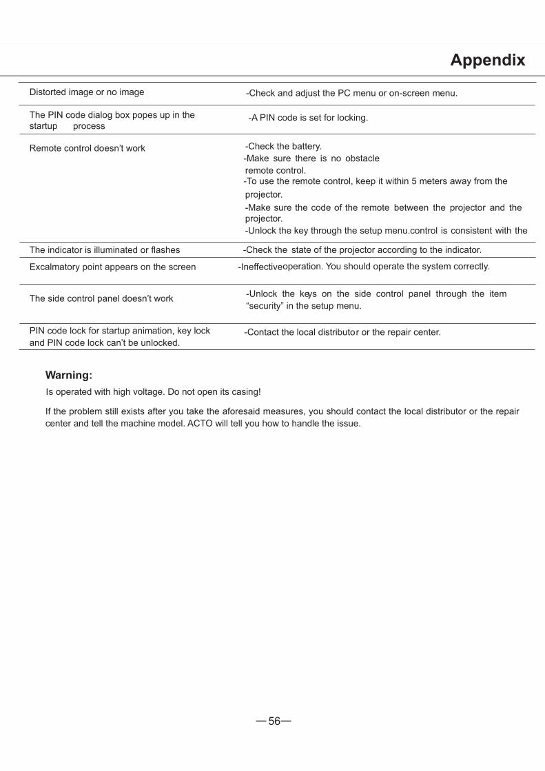
56
Appendix
Distorted image or no image -Check and adjust the PC menu or on-screen menu.
The PIN code dialog box popes up in thestartup process
-A PIN code is set for locking.
Remote control doesn’t work -Check the battery.-Make sure there is no obstacle
between the projector and the
remote control.-To use the remote control, keep it within 5 meters away from theprojector.-Make sure the code of the remote
control is consistent with theprojector.-Unlock the key through the setup menu.
The indicator is illuminated or flashes -Check the state of the projector according to the indicator.
Excalmatory point appears on the screen -Ineffectiveoperation. You should operate the system correctly.
The side control panel doesn’t work -Unlock the keys on the side control panel through the item“security” in the setup menu.
PIN code lock for startup animation, key lockand PIN code lock can’t be unlocked.
-Contact the local distributor or the repair center.
Warning:s operated with high voltage. Do not open its casing!
I
I
f the problem still exists after you take the aforesaid measures, you should contact the local distributor or the repaircenter and tell the machine model. ACTO will tell you how to handle the issue.

57
POWER WARNING LAMP SHIFT FOCUS
?
?
green red yellow off
green flash green flash
*When the projector bulbreaches its endurance, the indicator light will be yellow and you need tochange the bulb.
Appendix
Indicator and projector stateCheck the indicator to know about the state of projector.
Indicator
(Green/red) (Red) (Yellow) (Blue) (Green)
State of projector
Is in power-off state (AC power cord notinserted).
Is in standby state. Press ON/STNADBY topower on the projector.Is in normal working state.
Is ready to be in standby mode or theprojection lamp is being cooled. Before you poweron the projector, you should wait till the lamp is coolenough and the power indicator flashes.Is in suspension state.Internal temperature too high. can’t bepowered on. When the projector is cool enough, thetemperature is restored to the normal value and thepower indicator is illuminated red, you can thenpower on the projector (The indicator Warning Tempkeeps on flashing).When the projector is cool enough, the temperatureis restored to the normal value and the powerindicator is illuminated red, you can then power onthe projector, At the time, the indicator WarningTemp stops flashing. Can’t be powered on because error isdetected. You should unplug the power cord. Theninsert it again and power on the projector. If theprojector is powered off again, you should cut offthe power and contact the local distributor or repaircenter. In this case, stop the projector. Otherwise,electric shock or fire may occur.
The service life of the lamp is over. You shouldreplace it with a new one in time.
Lens is moving and being adjusted.
Focus being adjusted.
blue

58
640x400 60 1152x900 65640x400 70 1152x900 75640x400 85 1280x1024 60640x480 60 1280x1024 65640x480 65 1280x1024 70640x480 72 1280x1024 72640x480 75 1280x1024 75
640x480 85 1280x1024 85
800x600 50 WXGA 1280x768 60
800x600 60 1280x768 75800x600 65 1280x768 85800x600 72 1280x768 120800x600 75 1360x768 60800x600 85 1360x768 72800x600 120 1366x768 60
832x624 75 1280x800 60
XGA 1024x768 60 1280x800 751024x768 65 1280x800 85
1024x768 70 1280x800 120
1024x768 72 1080psf24 1920x1080 241024x768 75 1080psf25 1920x1080 25
1024x768 80 1080psf30 1920x1080 30
1024x768 85 480i 601024x768 120 575i 501152x864 70 480p 60
1035i 60 575p 501080i 60 720p 50
1080i 50 720p 60
SXGAVGA
SVGA
Appendix
Compatible PCsIs compatible with all analog and digital signal formats under 160MHz of DCLK, whose resolution andcorrespondent field frequencies are listed below:
Note:The specification is subject to change without prior notice.
Signal format Resolution Field frequency(HZ)Signal format Resolution Field frequency(HZ)

59
5 123410 9 678
15 14 13 1112
-----
1
5
2
4
3
6
7
8
-----9
13
10
12
11
14
15
RX –
TX +
TX –
RX +
2
3
4
87654321
5
6
7
8
1 -----
-----
----------
-----
R X D
T X D
-----
GND
-----
1
2
3
4
5
6
7
8
-----9
-----
-----
PIN code memorandumWrite down the PIN code in the blank below and keep it,please contact the repair center.
PIN code lock
*If this 3-digit number is changed,the factory default number will be ineffective.
Factory default PIN code 111*
Factory default PIN code 111*
Locking startup-animation PIN code
Appendix
Configuration of terminalsOMPUTER IN 1/COMPUTER IN 2/MONITOR OUT (analog)Terminal: Analog RGB (D-sub 15-pin)
CONTROL PORT terminal (D-SUB-9-Pin) LAN terminal
Red (Input/output)
Green (Input/output) Grounding (field synchronizing)
Blue (Input/output) GroundingDDC data
Grounding (line synchronizing) Horizontal synchronizing (compound sync.) input/output
Grounding (red) Vertical synchronizing input/outputGrounding (green) DDC clockGrounding (blue)

60
AppendixTechnical Specifications
Physical propertiesmm091xmm093xmm535)D×H×W(snoisnemidretuO
gk8.01thgiewteN°5elgnatoofelbatsujdA
Monitor’s resolutiondraob-3,xirtamevitca,TFT"97.0metsysDCL
stod867x420,1noitulosers’rotinoM
Compatible signalsTN,MACES,LAPdradnatsroloC SC, NTSC4.43, PAL-M and PAL-N
P0801dnai0801,i5301,p027,p575,i575,p084,i084langisVTDHerflatnoziroHycneuqerfgninnacS
frequency: 50–120 HzOptical elements
Image size (diagonal lines) 40”-400”, adjustableProjection distance 1.025m-17.48mLens F value: 1.7 -2.2; Electric zooming and focusing;
Zoom times: 1.6Lamp power 330w
TerminalInput terminal for chromatic aberration (video) RCA ×3 (repetitive use) SS terminal input terminal Mini DIN 4-pin x 1Input terminal for COMPUTER IN1/SCART Mini D-sub 15-pin x 1Terminal for COMPUTER IN 2/ SCART Mini D-sub 15-pin x 1nput terminal for RGBHV (video) BNC x 5(repetitive use)Input terminal for HDMI HDMI A interface 19-pin x 1Audio input terminal for COMPUTER 1/COMPUTER 2 Mini terminal (stereo) x 1Audio input terminal RCA ×2Audio output terminal Mini plug(stereo) ×1 (variable volume)Control terminal D-sub 9-pin x 1Network terminal 100 Base-TX (100 Mbps)/10 Base-T(10Mbps),RJ45
AudioEmbedded audio amplifier 7w single channelEmbedded speaker 7W RMS 4ohm, diameter, 28mm
Power supply Voltage and power consumption AC 100–240 V(Max. 6A),50/60 Hz
Operating environmentOperating temperaure 41F-95F (5C-35C)Storage temperature 14F-140F (-10C-60C)
Remote controlBattery AAA or LR03 1.5V alkali battery x 2Effective area 16.4' (5 m)/±30Outer dimensions 52mm (W) x 18mm (H) x 110mm (D)Net weight 67g (including battery)
AccessoriesUser’s ManualAC power cordRemote control and batteryVGA cable
The aforesaid specification is subject to change without prior notice.Liquid crystal panel is made on the basis of high standard, where 99.99% of the pixels are effective. Due to thenature of the liquid crystal panel, a fraction of the pixels (0.01% or less) may be ineffective.
Wide Monitor’s resolutionmetsysDCL
noitulosers’rotinoM draob-3,xirtamevitca,TFT"47.0stod008x082,1

61
300
150
238
58
10
534.5
193.4
176.9
146
380
5.
398
5.
465
1.
LCD PROJECTOR
LENS RELEASE
LCD PROJECTOR
114
Appendix
Outer dimensions
Content of hazardous substances and elements
Name of parts Hazardous substances and elements
Plastic parts Pb Hg Cd Cr6+ PBB PBDE
Metal partsOptical parts
PCB assembly ×
Body
Other parts ×Remote control ×
AccessoriesCable ×
: It means that contents of hazardous substancesin all homogeneous materials in this part don’texceed “Required Limitations”specified in SJ/T11363-2006.×: It means that contents of hazardous substances inat least one homogeneous material in this partexceed “Required Limitations” specified in SJ/T11363-2006.
Unit: mm
Screw hole used wheninstalled on the ceilingScrew:MBDepth:10.0

62
1.8-2.3 1.7-2.2 1.8-2.3 1.8-2.3
13.05
Flred/Power
NO YES YES YES YES
2.0
73.9-117.145.6-73.8 22-35 20.4-27.6
X1.3/Power X1.6/Power X1.6/Power X1.6/Power
Appendix
Optional parts
Wide-range lens tandard lens
Ultra-long -focuslens
Appearance
Electric
Zoom/FocusFoci(mm)
F value
Replacing lenslenIs s can be replaced by those of other models, a design that allows the projector to be used for
multi-purposes.If you want to install or replace the lens, you should contact the local distributor. Only qualified sales personnel orrepair engineers are permitted to install or replace the lens. To avoid injury, never attempt to install or replace thelens without permission.
When you need to lift or move, do not grasp the lens for that purpose. Otherwise, the projector
may be seriously damaged.
To sales personnel and repair engineers:For information on installation and replacement of lens, please refer to related operating instructions. Beforeinstalling or replacing the lens, make sure the model of the lens is correct.
Short-focus lens lens
TelephotoType
Listed below are optional parts. Users should provide distributors with such information as part name and modelwhen they place the order.