Low Voltage alternators - 4 pole LSA 402 ef : 4250 en Low Voltage alternators 4 pole 3-phase LSA 40...
12
Low Voltage alternators - 4 pole LSA 40 10 to 23 kVA - 50 Hz / 12.5 to 28 kVA - 60 Hz Electrical and mechanical data 4250 en - 2014.01 / f
Transcript of Low Voltage alternators - 4 pole LSA 402 ef : 4250 en Low Voltage alternators 4 pole 3-phase LSA 40...

Low Voltage alternators - 4 poleLSA 40
10 to 23 kVA - 50 Hz / 12.5 to 28 kVA - 60 Hz
Electrical and mechanical data 4250 en - 2014.01 / f
2 Ref : 4250 en
Low Voltage alternators 4 pole 3-phase LSA 4010 to 23 kVA - 50 Hz / 12.5 to 28 kVA - 60 Hz
SPECIALLY ADAPTED TO APPLICATIONSThe LSA 40 alternator is designed to be suitable for typical generator applications, such as: backup, marine applications, rental, telecommunications, etc.
COMPLIANT WITH INTERNATIONAL STANDARDSThe LSA 40 alternator conforms to the main international standards and regulations: ● IEC 60034, NEMA MG 1.32-33, ISO 8528/3, CSA, UL 1446, UL 1004 on request, marine regulations, etc.It can be integrated into a CE marked generator.The LSA 40 is designed, manufactured and marketed in an ISO 9001 environment.
TOP OF THE RANGE ELECTRICAL PERFORMANCE ● Class H insulation. ● Standard 12 wire re-connectable winding, 2/3 pitch, type no. 6. ● Voltage range: - 50 Hz: 220 V - 240 V and 380 V - 415 V (440 V) - 60 Hz: 208 V - 240 V and 380 V - 480 V ● High efficiency and motor starting capacity. ● Other voltages are possible with optional adapted windings: - 50 Hz: 440 V (no. 7), 500 V (no. 9), - 60 Hz: 380 V and 416 V (no. 8), 600 V (no. 9) ● R 791 interference suppression conforming to standard EN 55011 group 1 class B standard for European zone (CE marking).
EXCITATION AND REGULATION SYSTEM SUITED TO THE APPLICATION
Excitation system Regulation options
Voltage regulator SHUNT AREP
Currenttransformer
for parallelingMains
paralleling3-phasesensing
Remote voltagepotentiometer
R220 Std - - - - -R438 - Std C.T.* R726* R731* √
D510C* Option Option C.T.* included included √
AVR voltage accuracy ± 1% √: Possible mounting * External mounting
PROTECTION SYSTEM SUITED TO THE ENVIRONMENT ● The LSA 40 is IP 23. ● Standard winding protection for clean environments with relative humidity ≤ 95%, including indoor marine environments. ● Options: - filters on air inlet : derating 5%, - filters on air inlet and air outlet (IP 44) : derating 10%, - winding protection for harsh environments and relative humidity greater than 95%, - space heaters, - thermal protection for stator windings, - steel terminal box.
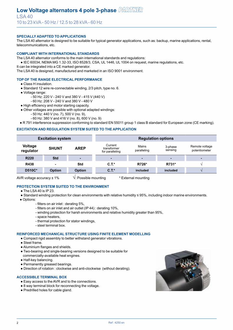
REINFORCED MECHANICAL STRUCTURE USING FINITE ELEMENT MODELLING ● Compact rigid assembly to better withstand generator vibrations. ● Steel frame. ● Aluminium flanges and shields. ● Two-bearing and single-bearing versions designed to be suitable for commercially-available heat engines. ● Half-key balancing. ● Permanently greased bearings. ● Direction of rotation : clockwise and anti-clockwise (without derating).
ACCESSIBLE TERMINAL BOX ● Easy access to the AVR and to the connections. ● 8 way terminal block for reconnecting the voltage. ● Predrilled holes for cable gland.

3
Phase 3 ph. 1 ph. 3 ph. 1 ph. 3 ph. 1 ph. 3 ph. 1 ph.Y 380V 400V 415V 440V ∆∆ 380V 400V 415V 440V ∆∆ 380V 400V 415V 440V ∆∆ 380V 400V 415V 440V ∆∆∆ 220V 230V 240V 230V 220V 230V 240V 230V 220V 230V 240V 230V 220V 230V 240V 230V
YY 220V 220V 220V 220V
40 VS1 kVA 10 10 10 9 7 9 9 9 8 6.5 10.5 10.5 10.5 9 7.5 11 11 11 10 8kW 8 8 8 7.2 5.6 7.2 7.2 7.2 6.4 5.2 8.4 8.4 8.4 7.2 6 8.8 8.8 8.8 8 6.4
40 VS2 kVA 12.5 12.5 12.5 11 9 11.5 11.5 11.5 10 8 13.5 13.5 13.5 12 9.5 14 14 14 12.5 10kW 10 10 10 8.8 7.2 9.2 9.2 9.2 8 6.4 10.8 10.8 10.8 9.6 7.6 11.2 11.2 11.2 10 8
40 S3 kVA 15 15 15 13 10.5 14 14 14 12 10 16 16 16 14 11.5 16.5 16.5 16.5 15 12kW 12 12 12 10.4 8.4 11.2 11.2 11.2 9.6 8 12.8 12.8 12.8 11.2 9.2 13.2 13.2 13.2 12 9.6
40 S4 kVA 17.5 17.5 17.5 16 12.5 16 16 16 14 11.5 19 19 19 16.5 13.5 19.5 19.5 19.5 17 14kW 14 14 14 12.8 10 12.8 12.8 12.8 11.2 9.2 15.2 15.2 15.2 13.2 10.8 15.6 15.6 15.6 13.6 11.2
40 M5 kVA 20 20 20 18 14 18.5 18.5 18.5 16 13 21.5 21.5 21.5 19 15 22 22 22 20 15.5kW 16 16 16 14.4 11.2 14.8 14.8 14.8 12.8 10.4 17.2 17.2 17.2 15.2 12 17.6 17.6 17.6 16 12.4
40 L7 kVA 23 23 23 19 15 20 20 20 16 14 24 24 24 20 16 25 25 25 22 16.5kW 18.4 18.4 18.4 15.2 12 16 16 16 12.8 11.2 19.2 19.2 19.2 16 12.8 20 20 20 17.6 13.2
Phase 3 ph. 1 ph. 3 ph. 1 ph. 3 ph. 1 ph. 3 ph. 1 ph.Y 380V 416V 440V 480V ∆∆ 380V 416V 440V 480V ∆∆ 380V 416V 440V 480V ∆∆ 380V 416V 440V 480V ∆∆∆ 220V 240V 240V 220V 240V 240V 220V 240V 240V 220V 240V 240V
YY 208V 220V 240V 208V 220V 240V 208V 220V 240V 208V 220V 240V
40 VS1 kVA 10 11 11.5 12.5 9 9.5 10.5 10.5 11.5 8.5 11 11.5 12.5 13.5 9.5 11.5 12 13 14 10kW 8.0 8.8 9.2 10.0 7.2 7.6 8.4 8.4 9.2 6.8 8.8 9.2 10 10.8 7.6 9.2 9.6 10.4 11.2 8
40 VS2 kVA 12.5 13.5 14.5 15.5 11.5 11.5 12.5 13.5 14.5 10.5 13.5 14.5 15.5 16.5 12 14 15 16 17 12.5kW 10.0 10.8 11.6 12.4 9.2 9.2 10 10.8 11.6 8.4 10.8 11.6 12.4 13.2 9.6 11.2 12 12.8 13.6 10
40 S3 kVA 15 16.5 17.5 19 13 14 15.5 16.5 17.5 12 16 18 19 20 13.5 17 18.5 19.5 21 14kW 12 13.2 14.0 15.2 10.4 11.2 12.4 13.2 14 9.6 12.8 14.4 15.2 16 10.8 13.6 14.8 15.6 16.8 11.2
40 S4 kVA 17.5 19 20 22 14.5 16.5 18 19 20.5 13 19 20.5 21.5 23.5 15 19.5 21 22 24.5 15.5kW 14.0 15.2 16.0 17.6 11.6 13.2 14.4 15.2 16.4 10.4 15.2 16.4 17.2 18.8 12 15.6 16.8 17.6 19.6 12.4
40 M5 kVA 20 22 23 25 16 18.5 20.5 21.5 23 15 21.5 23.5 25 27 17 22 24.5 26 27.5 17.5kW 16 17.6 18.4 20 12.8 14.8 16.4 17.2 18.4 12.0 17.2 18.8 20 21.6 13.6 17.6 19.6 20.8 22 14
40 L7 kVA 22 24.5 25.5 28 17.5 20.5 23 24 25 15.5 24 26 27.5 30 18.5 24.5 27 28.5 31 19.5kW 17.6 19.6 20.4 22.4 14 16.4 18.4 19.2 20 12.4 19.2 20.8 22 24 14.8 19.6 21.6 22.8 24.8 15.6
Ref : 4250 en
Low Voltage alternators 4 pole 3-phase LSA 4010 to 23 kVA - 50 Hz / 12.5 to 28 kVA - 60 Hz
kVA / kW - P.F. = 0.8Duty/T°C Continuous duty/40°C Continuous duty/40°C Stand-by/40°C Stand-by/27°CClass/T°K H/125°K F/105°K H/150°K H/163°K
Insulation class H Excitation system SHUNT AREPWinding pitch 2/3 (wdg 6) AVR type R 220 R 438Number of wires 12 Voltage regulation (*) ± 1% ± 0.5%Protection IP 23 Short-circuit current - 300% (3 IN): 10 sAltitude ≤ 1000 m Totale Harmonic distortion THD (**) in no-load ..... : < 3% according to IECOverspeed 2250 min-1 Totale Harmonic distortion THD (**) on linear load : < 5% according to IECAir flow 0.06 m3/s, 50 Hz - 0.072 m3/s, 60 Hz Waveform: NEMA = TIF (**) < 50(*) Steady state. (**) Total harmonic distortion between phases, in no-load or on linear load.
kVA / kW - P.F. = 0.8Duty/T°C Continuous duty/40°C Continuous duty/40°C Stand-by/40°C Stand-by/27°CClass/T°K H/125°K F/105°K H/150°K H/163°K
General characteristics
Ratings 60 Hz - 1800 R.P.M.
Ratings 50 Hz - 1500 R.P.M.

4
VS1 VS2 S3 S4 M5 L7Kcc 0.72 0.69 0.62 0.62 0.63 0.63Xd 167 174 190 195 193 192Xq 100 104 114 117 116 115
T’do 780 858 909 953 1006 1072X’d 17.2 16.3 16.8 16.4 15.4 14.4T’d 74 74 74 74 74 74X”d 8.6 8.1 8.4 8.2 7.7 7.2T”d 7 7 7 7 7 7X”q 16.1 15.9 16.8 16.8 16.2 15.6Xo 0.1 0.1 0.1 0.1 0.1 0.1X2 12.4 12.0 12.7 12.6 12.0 11.4Ta 11 11 11 11 11 11
io (A) 0.8 / 1.1 0.8 / 1.1 0.8 / 1.1 0.8 / 1.1 0.8 / 1 0.7 / 1ic (A) 2.0 / 2.7 2 / 2.8 2.1 / 2.9 2.1 / 2.9 2 / 2.7 2 / 2.7uc (V) 25 / 18 25 / 18 26 / 19 26 / 19 24 / 18 24 / 17
ms <300ms <300ms <300ms <300ms <300ms <300mskVA 25 29 36 44 52 62kVA 25 29 36 44 52 62% < 16% < 15.2% < 14.7% < 13.9% < 13.2% < 13.2%% < 16% < 15.2% < 14.7% < 13.9% < 13.2% < 13.2%W 460 520 550 600 660 730W 1610 1790 2040 2270 2360 2510
95%
90
85
80
751 2 3 4 5 6 7 8 9 10 11 12 kVA
LSA 40 VS1
77.2
79.7
83.283.8
82.783
86.888.5
88.788.8
95%
90
85
80
752 3 4 5 6 7 8 9 10 11 12 13 14 kVA
LSA 40 VS2
79.181.5
84.785.3 84.384.5
8889.6
89.789.8
95%
90
85
80
752 4 6 8 10 12 14 16 18 kVA
LSA 40 S3
8183.3
85.486.1 8585.7
8990.2 90.1
90.3
95%
90
85
80
752 4 6 8 10 12 14 16 18 20 kVA
LSA 40 S4
8284.1
8686.7
85.5
86.4
89.590.7 90.5
90.6
95%
90
85
80
752 4 6 8 10 12 14 16 18 20 22 kVA
LSA 40 M5
82.884.7
87.187.7 86.787.2
9091.2 91.2
91.3
95%
90
85
80
754 6 8 10 12 14 16 18 20 22 24 26 kVA
LSA 40 L7
83.685.3
87.988.5 87.687.9
90.591.7 91.7
91.8
Ref : 4250 en
Low Voltage alternators 4 pole 3-phase LSA 4010 to 23 kVA - 50 Hz / 12.5 to 28 kVA - 60 Hz
Short-circuit ratioDirect-axis synchro. reactance unsaturatedQuadrature-axis synchro. reactance unsaturatedNo-load transient time constantDirect-axis transient reactance saturatedShort-circuit transient time constantDirect-axis subtransient reactance saturatedSubtransient time constantQuadrature-axis subtransient reactance saturatedZero sequence reactance unsaturatedNegative sequence reactance saturatedArmature time constant
Other class H/400 V dataNo-load excitation current (SHUNT/AREP)On-load excitation current (SHUNT/AREP)On-load excitation voltage (SHUNT/AREP)Response time (∆U = 20% transient)Start (∆U = 20% cont. or ∆U = 30% trans.) SHUNTStart (∆U = 20% cont. or ∆U = 30% trans.) AREPTransient ∆U (on-load 4/4) SHUNT - P.F.: 0.8 LAG
Transient ∆U (on-load 4/4) AREP - P.F.: 0.8 LAG
No-load lossesHeat dissipation
Efficiencies 50 Hz (— P.F.: 0.8) (...... P.F.: 1 )
Reactances (%). Time constants (ms) - Class H / 400 V

5Ref : 4250 en
Low Voltage alternators 4 pole 3-phase LSA 4010 to 23 kVA - 50 Hz / 12.5 to 28 kVA - 60 Hz
Example of calculation for a P.F. with a other than 0.6 : motor starting kVA calculated at P.F. : 0.4 = 20 kVA Sin P.F. : 0.4 = 0.9165 K = 1.145 corrected kVA = 22.9 kVA Corresponding voltage drop for L7 = 14%.
0 20 40 60 kVA
Phase loading (SHUNT or AREP system)
kVA at P.F. : Ø 0.8
kVA at P.F. : Ø 0.8
Volta
ge d
rop
30%
25
20
15
10
5
Load shedding (SHUNT or AREP system)
Volta
ge ri
seVo
ltage
dro
p
40%
30
20
10
Motor starting (SHUNT or AREP system)
40%
30
20
10
locked rotor kVA at P.F. : Ø 0.6
1 ) For a P.F. with a Ø other than 0.6, multiply the kVA by K = Sin P.F. / 0.8
2 ) For a voltage U other than 400 V (Y), 230 V ( ) at 50 Hz , multiply the kVA by (400/U)2 or (230/U)2.
VS1 VS2 S3 S4 M5 L7
VS1 VS2 S3 S4 M5 L7
VS1 VS2 S3 S4 M5 L7
0 20 40 60 80 100 kVA
14%
22.9
0 20 40 60 kVA
Transient voltage variation 400V - 50 Hz

6
VS1 VS2 S3 S4 M5 L7Kcc 0.69 0.67 0.59 0.59 0.61 0.62Xd 174 180 201 204 201 195Xq 104 108 120 122 121 117
T’do 780 858 909 953 1006 1072X’d 17.9 16.8 17.8 17.2 16.1 14.6T’d 74 74 74 74 74 74X”d 8.9 8.4 8.9 8.6 8.0 7.3T”d 7 7 7 7 7 7X”q 16.7 16.4 17.8 17.6 16.9 15.9Xo 0.1 0.1 0.1 0.1 0.1 0.1X2 12.9 12.4 13.4 13.1 12.5 11.6Ta 11 11 11 11 11 11
io (A) 0.8 / 1.1 0.8 / 1.1 0.8 / 1.1 0.8 / 1.1 0.8 / 1 0.7 / 1ic (A) 2.0 / 2.8 2.0 / 2.8 2.2 / 2.9 2.2 / 2.9 2.0 / 2.8 1.9 / 2.6uc (V) 25 / 18 25 / 18 26 / 19 26 / 19 25 / 18 24 / 17
ms <300ms <300ms <300ms <300ms <300ms <300mskVA 30 35 43 53 62 74kVA 30 35 43 53 62 74% < 16.4% < 15.4% < 15.2% < 14.3% < 13.5% < 13.3%% < 16.4% < 15.4% < 15.2% < 14.3% < 13.5% < 13.3%W 650 730 770 840 920 1020W 1880 2080 2420 2670 2780 2870
90%
85
80
75
702 3 4 5 6 7 8 9 10 11 12 13 14 kVA
LSA 40 VS1
76.3
78.4
84.184.3 83.883
86.288.4
8989
95%
90
85
80
75
LSA 40 VS2
78.280.1
85.685.7 85.3
84.5
87.4
89.489.9
89.9
95%
90
85
80
75
2 4 6 8 10 12 14 16 18 kVA
LSA 40 S3
80.482.3
86.286.6 85.8
85.8
88.6 90.2 90.4
90.5
95%
90
85
80
75
LSA 40 S4
81.3
83.1
86.887.2
86.486.4
89.190.6 90.8
90.9
95%
90
85
80
75
LSA 40 M5
8283.6
87.788.1
87.487.2
89.691.1 91.4
91.4
95%
90
85
80
754 6 8 10 12 14 16 18 20 22 24 26 28 30 32 kVA
LSA 40 L7
82.583.9
88.688.8 88.3
87.7
89.991.5 91.8
91.8
2 4 6 8 10 12 14 16 18 20 kVA
4 6 8 10 12 14 16 18 20 22 24 26 kVA
4 6 8 10 12 14 16 18 20 22 24 26 28 kVA
Ref : 4250 en
Low Voltage alternators 4 pole 3-phase LSA 4010 to 23 kVA - 50 Hz / 12.5 to 28 kVA - 60 Hz
Short-circuit ratioDirect-axis synchro. reactance unsaturatedQuadrature-axis synchro. reactance unsaturatedNo-load transient time constantDirect-axis transient reactance saturatedShort-circuit transient time constantDirect-axis subtransient reactance saturatedSubtransient time constantQuadrature-axis subtransient reactance saturatedZero sequence reactance unsaturatedNegative sequence reactance saturatedArmature time constant
Other class H/480 V dataNo-load excitation current (SHUNT/AREP)On-load excitation current (SHUNT/AREP)On-load excitation voltage (SHUNT/AREP)Response time (∆U = 20% transient)Start (∆U = 20% cont. or ∆U = 30% trans.) SHUNTStart (∆U = 20% cont. or ∆U = 30% trans.) AREPTransient ∆U (on-load 4/4) SHUNT - P.F.: 0.8 LAG
Transient ∆U (on-load 4/4) AREP - P.F.: 0.8 LAG
No-load lossesHeat dissipation
Efficiencies 60 Hz (— P.F.: 0.8) (...... P.F.: 1 )
Reactances (%). Time constants (ms) - Class H / 480 V

7Ref : 4250 en
Low Voltage alternators 4 pole 3-phase LSA 4010 to 23 kVA - 50 Hz / 12.5 to 28 kVA - 60 Hz
Example of calculation for a P.F. with a P.F. other than 0.6: motor starting kVA calculated at P.F. 0.4 = 20 kVA Sin P.F. 0.4 = 0.9165 K = 1.145 corrected kVA = 22.9 kVA Corresponding voltage drop for L7 = 12%.
0 20 40 60 80 kVA
0 20 40 60 80 kVA
Phase loading (SHUNT or AREP system)
kVA at P.F. 0.8
kVA at P.F. 0.8
Volta
ge d
rop
30%
25
20
15
10
5
Load shedding (SHUNT or AREP system)
Volta
ge ri
seVo
ltage
dro
p
40%
30
20
10
Motor starting (SHUNT or AREP system)
40%
30
20
10
locked rotor kVA at P.F. : 0.6
VS1 VS2 S3 S4 M5 L7
VS1 VS2 S3 S4 M5 L7
VS1 VS2 S3 S4 M5 L7
0 20 40 60 80 100 120 kVA
12%
22.9
2 ) For a voltage U other than 480 V (Y), 277 V ( ), 240 V (YY) at 60 Hz, multiply the kVA by (480/U)2 or (277/U)2 or (240/U)2.
1 ) For a P.F. other than 0.6, multiply the kVA by K = Sin P.F. / 0.8
Transient voltage variation 480V - 60 Hz

8 Ref : 4250 en
Low Voltage alternators 4 pole 3-phase LSA 4010 to 23 kVA - 50 Hz / 12.5 to 28 kVA - 60 Hz
AREP
SHUNT
LSA 40 VS1
LSA 40 S3
Cur
rent
(A)
Cur
rent
(A)
Cur
rent
(A)
1 10 100 1000 10000
1000
100
10
time (ms)
time (ms)
time (ms) 1 10 100 1000 10000
1000
100
10
SHUNT
LSA 40 VS2
1 10 100 1000 10000
1000
100
10
SHUNT
AREP
AREP
Symmetrical Asymmetrical
Symmetrical Asymmetrical
Symmetrical Asymmetrical
Influence due to connectionCurves shown are for star (Y) connection.For other connections, use the following multiplication factors: - Series delta: Current value x 1.732 - Parallel star: Current value x 2
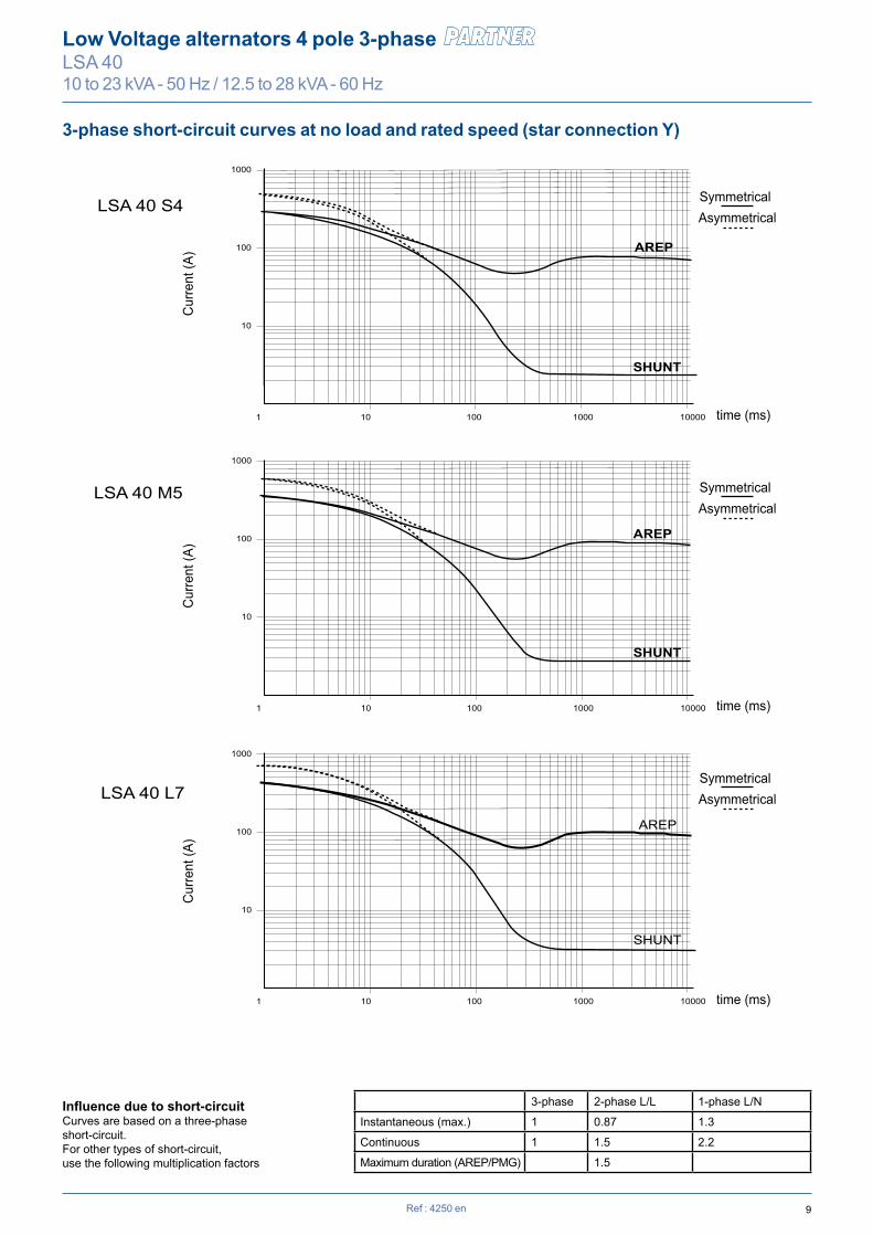
3-phase short-circuit curves at no load and rated speed (star connection Y)
9Ref : 4250 en
Low Voltage alternators 4 pole 3-phase LSA 4010 to 23 kVA - 50 Hz / 12.5 to 28 kVA - 60 Hz
AREP
SHUNT
LSA 40 S4
LSA 40 L7
Cur
rent
(A)
Cur
rent
(A)
Cur
rent
(A)
1 10 100 1000 10000
1000
100
10
time (ms)
time (ms)
time (ms) 1 10 100 1000 10000
1000
100
10
SHUNT
LSA 40 M5
1 10 100 1000 10000
1000
100
10
SHUNT
AREP
AREP
Symmetrical Asymmetrical
Symmetrical Asymmetrical
Symmetrical Asymmetrical
3-phase short-circuit curves at no load and rated speed (star connection Y)
Influence due to short-circuitCurves are based on a three-phaseshort-circuit.For other types of short-circuit, use the following multiplication factors
3-phase 2-phase L/L 1-phase L/N
Instantaneous (max.) 1 0.87 1.3
Continuous 1 1.5 2.2
Maximum duration (AREP/PMG) 1.5

10
L maxi * LB Xg 3 4 5LSA 40 VS1 467 405 186 73 H 160 180LSA 40 VS2 467 405 196 80 11 1/2 x - -LSA 40 S3 497 435 204 87 C 203 238 10 x x -LSA 40 M5 517 455 221 102 A1 254 279 7 1/2 - x xLSA 40 L7 547 485 236 112 A2 230 - 6 1/2 - x x
S.A.E. P N M XBG β° S.A.E. BX U X Y AH Z5 358 314.32 333.38 8 22°30 11 1/2 352.42 333.38 8 11 39.6 04 408 361.95 381 12 15° 10 314.32 295.28 8 11 53.8 03 460 409.58 428.62 12 15° 8 263.52 244.48 6 11 62 0
7 1/2 241.3 222.25 8 9 30.2 4.56 1/2 215.9 200.02 6 9 30.2 4.5
Xr Lr M J Xr Lr M J Xr Lr M J Xr Lr M J Xr Lr M JLSA 40 VS1 211.7 428 25.54 0.0779 211.7 428 25.7 0.0802 243.5 428 26 0.0847 238.3 428 26.5 0.0964 221.1 428 27 0.1080LSA 40 VS2 221.7 428 27.95 0.0867 221.7 428 28.11 0.0890 253.5 428 28.41 0.0935 248.3 428 28.91 0.1052 231.1 428 29.41 0.1168LSA 40 S3 229.2 458 30.32 0.0936 229.2 458 30.48 0.0959 261 458 30.78 0.1004 255.8 458 31.28 0.1121 238.6 458 31.78 0.1237LSA 40 S4 236.7 458 32.23 0.1004 236.7 458 32.39 0.1027 268.5 458 32.69 0.1072 263.3 458 33.19 0.1189 246.1 458 33.69 0.1305LSA 40 M5 246.7 478 35.26 0.1102 246.7 478 35.42 0.1125 278.5 478 35.72 0.1170 273.3 478 36.22 0.1287 256.1 478 36.72 0.1403LSA 40 L7 261.7 508 39.47 0.1237 261.7 508 39.63 0.1260 293.5 508 39.93 0.1305 288.3 508 40.43 0.1422 271.1 508 40.93 0.1538
Ø 5
5
Ø 5
2
Ø 4
1
Ø 2
5
Ø 5
0
Ø 1
8
Lr
Xr
* L maxi = LB + AH maxi
Ref : 4250 en
Low Voltage alternators 4 pole 3-phase LSA 4010 to 23 kVA - 50 Hz / 12.5 to 28 kVA - 60 Hz
Centre of gravity: Xr (mm), Rotor length: Lr (mm), Weight: M (kg), Moment of inertia: J (kgm2): (4J = MD2)Flex plate S.A.E. 6 1/2 Flex plate S.A.E. 7 1/2 Flex plate S.A.E. 8 Flex plate S.A.E. 10 Flex plate S.A.E. 11 1/2
Type
Ø B
X
Ø NØ P
AHZ
C1
87.5
3
- 0.0
50- 0
.100
+ 0
- 0.1
27
5.5203 C 3
5.5 51
Ø 2
85
13
β°
AIR OUTLETAIR OUTLET
X Ø Y holes equid. over Ø U
Ø 53 130
Ø B
X
Ø NØ P
- 0.0
50- 0
.100
+ 0
- 0.1
27
L L LBLB
9813
80
XgXg212 47AH
Z 5081
123.5
AIRINLET
349
H21
337
3
4+1 -3
A2A1
282
Access to terminalsand AVR
XBG Ø 11 holes equid. over Ø M
Cableoutlet
Detail of S.A.E. 5 flange
OptionalH = 180
Single bearing dimensions
Torsional analysis data
NOTE : Dimensions are for information only and may be subject to modifications. Contractuel 2D drawings can be downloaded from the Leroy-Somer site, 3D drawing files are available upon request.
Dimensions (mm) and weight Standard Option CouplingType Weight (kg) Hauteur d’axe Flange
Flex plate
Feet length
Flange (mm) Flex plate (mm)
11
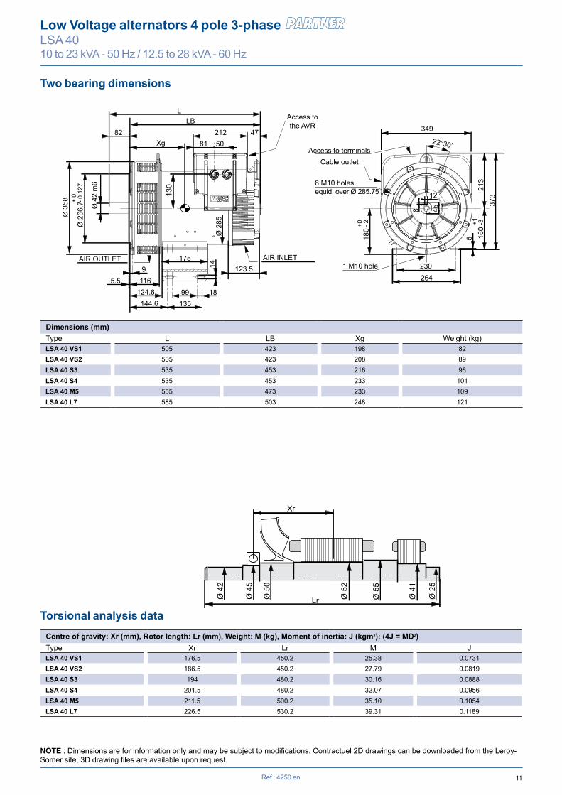
L LB XgLSA 40 VS1 505 423 198 82LSA 40 VS2 505 423 208 89LSA 40 S3 535 453 216 96LSA 40 S4 535 453 233 101LSA 40 M5 555 473 233 109LSA 40 L7 585 503 248 121
Xr Lr M J LSA 40 VS1 176.5 450.2 25.38 0.0731LSA 40 VS2 186.5 450.2 27.79 0.0819LSA 40 S3 194 480.2 30.16 0.0888LSA 40 S4 201.5 480.2 32.07 0.0956LSA 40 M5 211.5 500.2 35.10 0.1054LSA 40 L7 226.5 530.2 39.31 0.1189
Ø 5
5
Ø 5
2
Lr
Xr
Ø 4
1
Ø 2
5
Ø 5
0
Ø 4
5
Ø 4
2
Ref : 4250 en
Low Voltage alternators 4 pole 3-phase LSA 4010 to 23 kVA - 50 Hz / 12.5 to 28 kVA - 60 Hz
Dimensions (mm)Type Weight (kg)
Centre of gravity: Xr (mm), Rotor length: Lr (mm), Weight: M (kg), Moment of inertia: J (kgm2): (4J = MD2)Type
L LB
349
Xg
Ø 2
66.7
14
Ø 4
2 m
6
Ø 3
58 + 0
- 0.1
27
9
135
175
99 18116
124.6144.6
5.5
212 47
Ø 2
85
508182
160
213
22°30’
373
5
+1 -3
180
+0 - 2
230 264
AIR OUTLET
Access to terminals
8 M10 holes equid. over Ø 285.75
1 M10 hole
Access to the AVR
Cable outlet
12
8 45
130
123.5AIR INLET
Two bearing dimensions
Torsional analysis data
NOTE : Dimensions are for information only and may be subject to modifications. Contractuel 2D drawings can be downloaded from the Leroy-Somer site, 3D drawing files are available upon request.

2013
.10
/ a
Moteurs Leroy-Somer SAS - RCS 338 567 258 ANGOULÊME - Capital de 65 800 512 €
www.leroy-somer.com
Contact
en -
© - This document is the property of Moteurs Leroy-Somer, it can not be reproduced in any form without prior written authorization.Moteurs Leroy-Somer reserves the right to modify the design, technical speci�cations and dimensions of the products shown in this document.
The descriptions cannot in any way be considered contractual.