Low Voltage alternators - 4 pole LSA 49Low Voltage alternators - 4 pole LSA 49.1 660 to 1000 kVA -...
12
Low Voltage alternators - 4 pole LSA 49.1 660 to 1000 kVA - 50 Hz / 792 to 1250 kVA - 60 Hz Electrical and mechanical data 3867 en - 2014.05 / h
Transcript of Low Voltage alternators - 4 pole LSA 49Low Voltage alternators - 4 pole LSA 49.1 660 to 1000 kVA -...

Low Voltage alternators - 4 poleLSA 49.1
660 to 1000 kVA - 50 Hz / 792 to 1250 kVA - 60 Hz
Electrical and mechanical data3867 en - 2014.05 / h

2 Ref : 3867 en
Low Voltage alternators 4 pole 3-phase LSA 49.1660 to 1000 kVA - 50 Hz / 792 to 1250 kVA - 60 Hz
SPECIALLY ADAPTED TO APPLICATIONSThe LSA 49.1 alternator is designed to be suitable for typical generator applications, such as: backup, marine applications, rental, telecommunications, etc.
COMPLIANT WITH INTERNATIONAL STANDARDSThe LSA 49.1 alternator conforms to the main international standards and regulations: - IEC 60034, NEMA MG 1.32-33, ISO 8528-3, CSA / UL 1446 (UL 1004 on request), marine regulations, etc.It can be integrated into a CE marked generator.The LSA 49.1 is designed, manufactured and marketed in an ISO 9001 environment and ISO 14001.
TOP OF THE RANGE ELECTRICAL PERFORMANCE ● Class H insulation. ● Standard 6-wire re-connectable winding, 2/3 pitch, type no. 6. ● Voltage range 50 Hz: 380V - 400V - 415V and 220V - 230V - 240V. ● Voltage range 60 Hz: 380V - 416V - 440V - 480V and 220 V - 240 V. ● High efficiency and motor starting capacity. ● Other voltages are possible with optional adapted windings: - 50 Hz : 440 V (no. 7), 500 V (no. 9), 600 V (no. 22 or 23), 690 V (no. 10 or 52). - 60 Hz : 380 V and 416 V (no. 8), 600 V (no. 9). ● R 791 interference suppression conforming to standard EN 55011 group 1 class B standard for European zone (CE marking).
EXCITATION AND REGULATION SYSTEM SUITED TO THE APPLICATION
Excitation system Regulation options
Volageregulator AREP PMG
Current transformer
for parallelingMains
paralleling3-phasesensing
3-phase sensing formains paralleling
unbalancedRemote voltagepotentiometer
R450 Std Option C.T. R726 R731 R734 √D510C Option Option C.T. included included contact factory √
Voltage regulator accuracy ± 0.5% - √ : possible mounting PROTECTION SYSTEM SUITED TO THE ENVIRONMENT ● The LSA 49.1 is IP 23. ● Standard winding protection for clean environments with relative humidity ≤ 95 %, including indoor marine environments. Options : ● Filters on air inlet : derating 5%. ● Filters on air inlet and air outlet (IP 44) : derating 10%. ● Winding protections for harsh environments and relative humidity greater than 95%. ● Space heaters. ● Thermal protection for winding.
REINFORCED MECHANICAL STRUCTURE USING FINITE ELEMENT MODELLING ● Compact and rigid assembly to better withstand generator vibrations. ● Steel frame. ● Cast iron flanges and shields. ● Twin-bearing and single-bearing versions designed to be suitable for engines on the market. ● Half-key balancing. ● Regreasable bearings. ● Standard direction of rotation: clockwise when looking at the drive end view (for anti-clockwise, derate the machine by 5%).
ACCESSIBLE TERMINAL BOX PROPORTIONED FOR OPTIONAL EQUIPMENT ● Easy access to the voltage regulator and to the connections. ● Possible inclusion of accessories for paralleling, protection and measurement. ● Connection bar for reconnecting voltage.

3
Phase 3 ph. 3 ph. 3 ph. 3 ph.Y 380V 400V 415V 380V 400V 415V 380V 400V 415V 380V 400V 415V
∆ 220V 230V 240V 220V 230V 240V 220V 230V 240V 220V 230V 240V
LSA 49.1 S4 kVA 660 660 660 594 594 594 693 693 693 725 725 725kW 528 528 528 475 475 475 554 554 554 580 580 580
LSA 49.1 M6 kVA 725 725 725 653 653 653 760 760 760 800 800 800kW 580 580 580 522 522 522 608 608 608 640 640 640
LSA 49.1 M75 kVA 775 800 775 698 720 698 810 840 810 850 880 850kW 620 640 620 558 576 558 648 672 648 680 704 680
LSA 49.1 L9 kVA 880 880 880 792 792 792 920 920 920 960 960 960kW 704 704 704 634 634 634 736 736 736 768 768 768
LSA 49.1 L10 kVA 890 910 890 800 820 800 934 955 934 979 1000 979kW 712 728 712 640 656 640 747 764 747 783 800 783
LSA 49.1 L11 kVA 1000 1000 1000 910 910 910 1050 1050 1050 1100 1100 1100kW 800 800 800 728 728 728 840 840 840 880 880 880
Phase 3 ph. 3 ph. 3 ph. 3 ph.Y 380V 416V 440V 480V 380V 416V 440V 480V 380V 416V 440V 480V 380V 416V 440V 480V
∆ 220V 240V 220V 240V 220V 240V 220V 240V
LSA 49.1 S4 kVA 710 710 725 792 639 639 652 712 745 745 760 830 781 781 798 871kW 568 568 580 634 511 511 522 570 596 596 608 664 625 625 638 697
LSA 49.1 M6 kVA 780 780 800 870 702 702 720 783 819 819 840 913 858 858 880 957kW 624 624 640 696 562 562 576 626 655 655 672 730 686 686 704 766
LSA 49.1 M75 kVA 866 936 960 960 780 842 865 865 910 983 1008 1008 953 1030 1056 1056kW 693 749 768 768 624 674 692 692 728 786 806 806 762 824 845 845
LSA 49.1 L9 kVA 910 980 1010 1056 819 882 909 950 955 1029 1060 1108 1000 1078 1111 1162kW 728 784 808 845 655 706 727 760 764 823 848 886 800 862 889 930
LSA 49.1 L10 kVA 958 1020 1050 1092 862 918 945 983 1006 1071 1102 1146 1054 1122 1155 1200kW 766 816 840 874 690 734 756 786 805 857 882 917 843 898 924 960
LSA 49.1 L11 kVA 1000 1080 1145 1250 900 980 1040 1140 1040 1135 1200 1310 1090 1190 1260 1375kW 800 864 916 1000 720 784 832 912 832 908 960 1048 872 952 1008 1100
Ref : 3867 en
Low Voltage alternators 4 pole 3-phase LSA 49.1660 to 1000 kVA - 50 Hz / 792 to 1250 kVA - 60 Hz
kVA / kW - P.F. = 0.8Duty/T°C Continuous duty/40°C Continuous duty/40°C Stand-by/40°C Stand-by/27°CClass/T°K H/125°K F/105°K H/150°K H/163°K
General characteristics
Ratings 60 Hz - 1800 R.P.M.
Ratings 50 Hz - 1500 R.P.M.
kVA / kW - P.F. = 0.8Duty/T°C Continuous duty/40°C Continuous duty/40°C Stand-by/40°C Stand-by/27°CClass/T°K H/125°K F/105°K H/150°K H/163°K
Insulation class H Air flow L11 1.2 m3/s (50 Hz) - 1.4 m3/s (60 Hz)Winding pitch 2/3 (n° 6S) Excitation system AREP or PMGNumber of wires 6 AVR type R 450Protection IP 23 Voltage regulation (*) ± 0.5 %Altitude ≤ 1000 m Short-circuit current 300% (3 IN) : 10sOverspeed 2250 min-1 Totale Harmonic distortion THD (**) at no load < 4 % - on load < 4 %Air flow except L11 1 m3/s (50 Hz) - 1.2 m3/s (60 Hz) Waveform: NEMA = TIF (**) < 50(*) Steady state. (**) Total harmonic distortion between phases, no-load or on-load (non-distorting)

4
S4 M6 M75 L9 L10 L11Kcc 0.38 0.43 0.39 0.43 0.41 0.37Xd 343 301 332 304 315 346Xq 205 180 199 182 189 207
T’do 1958 2047 2047 2111 2111 2111X’d 17.5 14.7 16.2 14.4 14.9 16.4T’d 100 100 100 100 100 100X”d 14 11.7 12.9 11.5 11.9 13.1T”d 10 10 10 10 10 10X”q 16.3 13.1 14.5 12.5 13 14.3Xo 0.9 0.7 0.8 0.8 0.9 0.9X2 15.2 12.5 13.8 12.1 12.5 13.7Ta 15 15 15 15 15 15
io (A) 0.9 0.9 0..9 0.9 0.9 0.8ic (A) 3.6 3.2 3.5 3.3 3.4 3.2uc (V) 43 38 41 39 40 38
ms 500 500 500 500 500 500kVA 1578 1985 1985 2372 2372 2372% 13.3 10.9 11.7 10.7 11 11.8W 8110 9000 9000 9860 9860 11050W 33710 32740 37700 35340 37030 41710
Ref : 3867 en
Low Voltage alternators 4 pole 3-phase LSA 49.1660 to 1000 kVA - 50 Hz / 792 to 1250 kVA - 60 Hz
Short-circuit ratioDirect-axis synchro. reactance unsaturatedQuadrature-axis synchro. reactance unsaturatedNo-load transient time constantDirect-axis transient reactance saturatedShort-circuit transient time constantDirect-axis subtransient reactance saturatedSubtransient time constantQuadrature-axis subtransient reactance saturatedZero sequence reactance unsaturatedNegative sequence reactance saturatedArmature time constant
Other class H/400 V dataNo-load excitation currentOn-load excitation currentOn-load excitation voltageResponse time (∆U = 20% transient)Start (∆U = 20% cont. or 50% trans.) Transient ∆U (on-load 4/4) - P.F.: 0.8 LAG
No-load lossesHeat dissipation
Efficiencies 50 Hz - P.F.: 1 / P.F.: 0.8
Reactances (%). Time constants (ms) - Class H / 400 V
97%
96
95
94
93
92100 200 300 400 500 600 700 800 kVA
93.7
95.896.1
96
94.6
95.8
92.9
94.5 93.9
93.7
LSA 49.1 S4
P.F. : 1
P.F. : 0.8
97%
96
95
94
93
92100 200 300 400 500 600 700 800 kVA
93.8
9696.4
96.3
94.9
96.2
93
95 94.6
94.4
LSA 49.1 M6
P.F. : 1
P.F. : 0.8
97%
96
95
94
93
92100 200 300 400 500 600 700 800 900 1000kVA
94.2
96.196.4
96.2
95
96.1
93.4
94.9 94.4
94.1
LSA 49.1 M75
P.F. : 1
P.F. : 0.8
97%
96
95
94
93
92100 200 300 400 500 600 700 800 900 1000 kVA
94.3
96.4 96.7
96.7
95.4
96.6
93.7
95.595.2
95
LSA 49.1 L9 P.F. : 1
P.F. : 0.8
100 200 300 400 500 600 700 800 900 1000 kVA
94.5
96.496.7
96.7
95.4
96.6
93.8
95.595.1
94.9
LSA 49.1 L10 P.F. : 1
P.F. : 0.8
97%
96
95
94
93
92
97%
96
95
94
93
92100 200 300 400 500 600 700 800 900 1000 1100 kVA
94.4
96.396.7
96.6
95.4
96.5
93.8
95.4 95
94.8
LSA 49.1 L11 P.F. : 1
P.F. : 0.8
5Ref : 3867 en
Low Voltage alternators 4 pole 3-phase LSA 49.1660 to 1000 kVA - 50 Hz / 792 to 1250 kVA - 60 Hz
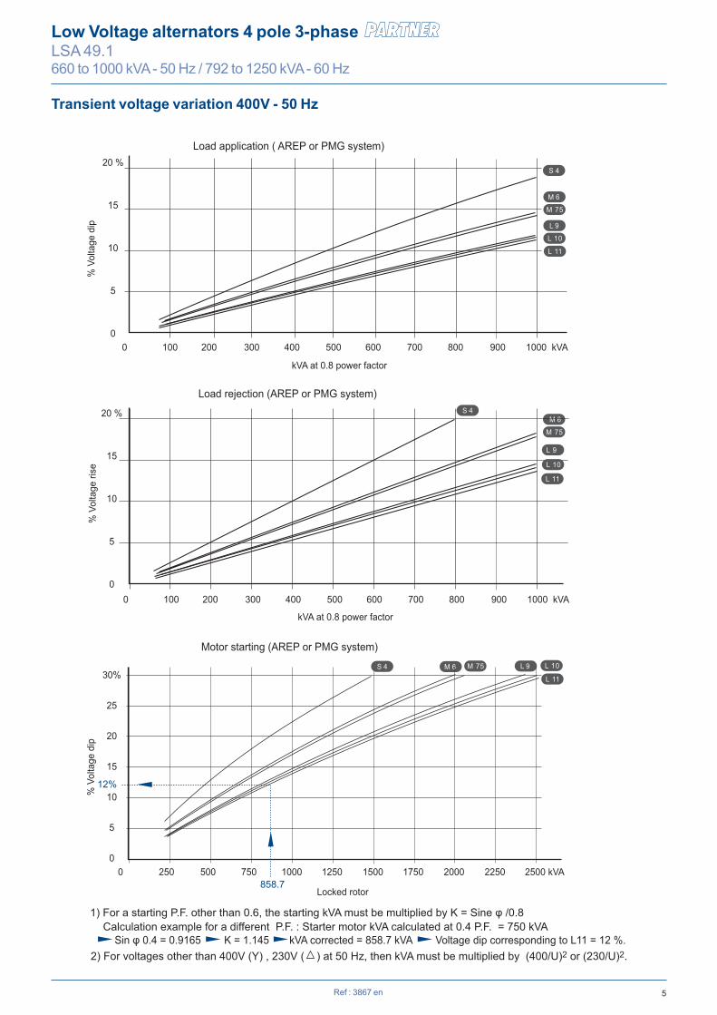
Transient voltage variation 400V - 50 Hz
S 4
M 6
L 9
20 %
15
10
5
0
M 75
L 10
0 250 500 750 1000 1250 1500 1750 2000 2250 2500 kVA
30%
25
20
15
10
5
0
0 100 200 300 400 500 600 700 800 900 1000 kVA
0 100 200 300 400 500 600 700 800 900 1000 kVA
S 4
S 4
M 6
M 6 L 9
20 %
15
10
5
0
M 75
M 75
L 10
L 9
L 10
Load application ( AREP or PMG system)
kVA at 0.8 power factor
kVA at 0.8 power factor
% V
olta
ge d
ip
Load rejection (AREP or PMG system)
% V
olta
ge ri
se%
Vol
tage
dip
Motor starting (AREP or PMG system)
Locked rotor
Calculation example for a different P.F. : Starter motor kVA calculated at 0.4 P.F. = 750 kVA Sin φ 0.4 = 0.9165 K = 1.145 kVA corrected = 858.7 kVA Voltage dip corresponding to L11 = 12 %.
1) For a starting P.F. other than 0.6, the starting kVA must be multiplied by K = Sine φ /0.8
2) For voltages other than 400V (Y) , 230V ( ) at 50 Hz, then kVA must be multiplied by (400/U)2 or (230/U)2.
L 11
L 11
L 11
12%
858.7

6
S4 M6 M75 L9 L10 L11Kcc 0.38 0.43 0.39 0.43 0.41 0.36Xd 343 301 332 304 315 360Xq 205 180 199 182 189 216
T’do 1958 2047 2047 2111 2111 2111X’d 17.5 14.7 16.2 14.4 14.9 17T’d 100 100 100 100 100 100X”d 14 11.7 12.9 11.5 11.9 13.6T”d 10 10 10 10 10 10X”q 16.3 13.1 14.5 12.5 13 14.9Xo 0.9 0.7 0.8 0.8 0.9 0.9X2 15.2 12.5 13.8 12.1 12.5 14.3Ta 15 15 15 15 15 15
io (A) 0.9 0.9 0.9 0.9 0.9 0.8ic (A) 3.6 3.2 3.5 3.2 3.3 3.2uc (V) 42 38 41 38 39 38
ms 500 500 500 500 500 500kVA 1950 2482 2482 2972 2972 2972% 13.3 10.9 11.7 10.7 11 12.2W 12570 13820 13820 15030 15030 17160W 39100 38520 43730 41600 43380 51950
Ref : 3867 en
Low Voltage alternators 4 pole 3-phase LSA 49.1660 to 1000 kVA - 50 Hz / 792 to 1250 kVA - 60 Hz
Short-circuit ratioDirect-axis synchro. reactance unsaturatedQuadrature-axis synchro. reactance unsaturatedNo-load transient time constantDirect-axis transient reactance saturatedShort-circuit transient time constantDirect-axis subtransient reactance saturatedSubtransient time constantQuadrature-axis subtransient reactance saturatedZero sequence reactance unsaturatedNegative sequence reactance saturatedArmature time constant
Other class H/480 V dataNo-load excitation currentOn-load excitation currentOn-load excitation voltageResponse time (∆U = 20% transient)Start (∆U = 20% cont. or 50% trans.) Transient ∆U (on-load 4/4) - P.F.: 0.8 LAG
No-load lossesHeat dissipation
Efficiencies 60 Hz - P.F.: 1 / P.F.: 0.8
Reactances (%). Time constants (ms) - Class H / 480 V
96%
95
94
93
92
91
96%
95
94
93
92
91
100 200 300 400 500 600 700 800 900 kVA
92.3
95.2
95.8
95.9
94.1
95.8
91.6
94.494.1
93.9
LSA 49.1 S4 P.F. : 1
P.F. : 0.8
97%
96
95
94
93
92100 200 300 400 500 600 700 800 900 1000 1100 kVA
93
95.696.1
96.2
94.6
96.1
92.3
94.894.6
94.4
LSA 49.1 M75
P.F. : 1
P.F. : 0.8
97%
96
95
94
93
92200 300 400 500 600 700 800 900 1000 1100 1200 kVA
93.1
95.8
96.5
96.6
95
96.6
926
95.495.3
95.1
LSA 49.1 L9 P.F. : 1
P.F. : 0.8
P.F. : 0.8
97%
96
95
94
93
92200 300 400 500 600 700 800 900 1000 1100 1200 kVA
93.3
95.996.5
96.6
95
96.6
928
95.495.2
95.1
P.F. : 1
P.F. : 1
P.F. : 0.8
LSA 49.1 L10
100 200 300 400 500 600 700 800 900 1000 kVA
92.4
95.396.1
96.2
94.4
96.2
91.8
94.994.7
94.6
LSA 49.1 M6 P.F. : 1
P.F. : 0.8
97%
96
95
94
93
92200 400 600 800 1000 1200 1400kVA
93.3
95.8
96.4
96.4
95
96.4
928
95.395
94.8
LSA 49.1 L11
7Ref : 3867 en
Low Voltage alternators 4 pole 3-phase LSA 49.1660 to 1000 kVA - 50 Hz / 792 to 1250 kVA - 60 Hz
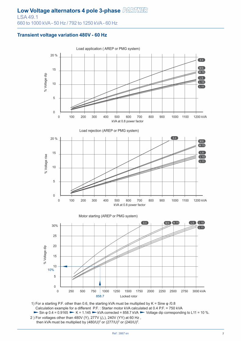
Transient voltage variation 480V - 60 Hz
0 100 200 300 400 500 600 700 800 900 1000 1100 1200 kVA
0 100 200 300 400 500 600 700 800 900 1000 1100 1200 kVA
S 4
M 6
L 9
20 %
15
10
5
0
M 75
L 10
L 11
L 11
0 250 500 750 1000 1250 1500 1750 2000 2250 2500 2750 3000 kVA
30%
25
20
15
10
5
0
S 4
S 4 M 6 L 9
20 %
15
10
5
0
M 6
L 9
M 75
M 75
L 10
L 10
L 11
10%
858.7
Load application ( AREP or PMG system)
kVA at 0.8 power factor
kVA at 0.8 power factor
% V
olta
ge d
ip
Load rejection (AREP or PMG system)
% V
olta
ge ri
se%
Vol
tage
dip
Motor starting (AREP or PMG system)
Locked rotor
2 ) For voltages other than 480V (Y), 277V ( ), 240V (YY) at 60 Hz , then kVA must be multiplied by (480/U)2 or (277/U)2 or (240/U)2.
Calculation example for a different P.F. : Starter motor kVA calculated at 0.4 P.F. = 750 kVA Sin φ 0.4 = 0.9165 K = 1.145 kVA corrected = 858.7 kVA Voltage dip corresponding to L11 = 10 %.
1) For a starting P.F. other than 0.6, the starting kVA must be multiplied by K = Sine φ /0.8

8 Ref : 3867 en
Low Voltage alternators 4 pole 3-phase LSA 49.1660 to 1000 kVA - 50 Hz / 792 to 1250 kVA - 60 Hz
Influence due to connectionCurves shown are for star (Y) connection.For other connections, use the following multiplication factors: - Series delta : current value x 1.732 - Parallel star : current value x 2
3-phase short-circuit curves at no load and rated speed (star connection Y)
LSA 49.1 S4
LSA 49.1 M75
1 10 100 1000 10000
100000
10000
1000
100
1 10 100 1000 10000
100000
10000
1000
100
LSA 49.1 M6
1 10 100 1000 10000
100000
10000
1000
100
Cur
rent
(A)
time (ms)
Symmetrical Asymmetrical
Cur
rent
(A)
time (ms)
Symmetrical Asymmetrical
Cur
rent
(A)
time (ms)
Symmetrical Asymmetrical

9Ref : 3867 en
Low Voltage alternators 4 pole 3-phase LSA 49.1660 to 1000 kVA - 50 Hz / 792 to 1250 kVA - 60 Hz
Influence due to short-circuitCurves are based on a three-phaseshort-circuit.For other types of short-circuit, use the following multiplication factors.
3-phase 2-phase L/L 1-phase L/N
Instantaneous (max.) 1 0.87 1.3
Continuous 1 1.5 2.2
Maximum duration (AREP/PMG) 10 sec. 5 sec. 2 sec.
3-phase short-circuit curves at no load and rated speed (star connection Y)
LSA 49.1 L9
LSA 49.1 L10
1 10 100 1000 10000
100000
10000
1000
100
1 10 100 1000 10000
100000
10000
1000
100
Cur
rent
(A)
time (ms)
Symmetrical Asymmetrical
Cur
rent
(A)
Cur
rent
(A)
time (ms)
time (ms)
Symmetrical Asymmetrical
LSA 49.1 L11
1 10 100 1000 10000
100000
10000
1000
100
Symmetrical Asymmetrical

10
Ø 1
50
Ø 1
45
Ø 1
40
Ø 1
00
Xr (S4, M6, M75, L9, L10)
Lr Ø 1
45
Ø 1
35
Ø 1
30
Ø 1
50
Ø 1
45
Ø 1
40
Ø 1
00
Xr (L11)
Lr Ø 1
45
Ø 1
35
Ø 1
30
Xr Lr M J Xr Lr M J LSA 49.1 S4 601 1280 536 8.51 591 1280 539 8.76LSA 49.1 M6 651 1380 618 10.14 641 1380 621 10.39LSA 49.1 M75 651 1380 618 10.14 641 1380 621 10.39LSA 49.1 L9 701 1480 700 11.78 691 1480 703 12.03LSA 49.1 L10 701 1480 700 11.78 691 1480 703 12.03LSA 49.1 L11 676 1456 747 13.43 672 1456 751 13.70
LB C Xg 14 18LSA 49.1 S4 1315 1272 560 635 1420 X*LSA 49.1 M6 1415 1372 650 670 1620 X*LSA 49.1 M75 1415 1372 650 670 1620 X* XLSA 49.1 L9 1515 1472 650 710 1820 XLSA 49.1 L10 1515 1472 650 710 1820LSA 49.1 L11 1480 1448 650 686 1945
S.A.E. P N M W R CF S.A.E. BX U X Y AH1 753 511.175 530.225 7 438 17 14 466.7 438.15 8 14 25.4
1/2 753 584.2 619.125 6 438 17 18 571.5 542.92 6 17 15.7 0* 753 647.7 679.45 7 438 17
00* 885 787.4 850.9 6 505 15
Ref : 3867 en
Low Voltage alternators 4 pole 3-phase LSA 49.1660 to 1000 kVA - 50 Hz / 792 to 1250 kVA - 60 Hz
Single bearing dimensions
L
C 216
LBXg
Ø B
X
Ø N
Ø P
AH792
686 786
658
40
0
1058
27
Diodeaccess
11°15'
6
0 - 0,1
27
- 0,0
50- 0
,100
17
W
CF
626
Air inlet
2 x 2 hole Ø 35Ø
742
37
85,3
300 281
AVRaccess
100
Ø 230
0 - 1
90
ROption
Ø 2
35
Option PMG
C
213,5
Xg
Air outlet Air outlet
Ø B
X
Ø N
Ø 8
83
AH
6
0 - 0,1
27
- 0,0
50- 0
,100
15,7
7
CF
Detail : LSA 49.1 L11Flange SAE : 0 & 00
Y DIA, X eq. sp. hole on U PCD
14 DIA, 16 eq. sp. hole on M PCD
NOTE: dimensions are for information only and may be subject to modifications. Contractuel 2D drawings (.pdf files) can be downloaded from the Leroy-Somer site, 3D drawing files are available upon request.
Dimensions (mm) and weightType
Flange (mm) Flex plate (mm)
Weight (kg)L without PMG
Flange S.A.E 1/2*Flange S.A.E 1*
CouplingFlex plate
Torsional analysis data
Centre of gravity: Xr (mm), Rotor length: Lr (mm), Weight: M (kg), Moment of inertia: J (kgm2): (4J = MD2)Flange S.A.E. 14 Flange S.A.E. 18
Type
Flange S.A.E 00Flange S.A.E 0
* : not available for LSA 49.1 L11
* : see the flange detail for LSA 49.1 L11 SAE 0 & 00.

11
LB M R XgLSA 49.1 S4 1419 1254 679.45 438 620 1445LSA 49.1 M6 1519 1354 679.45 438 655 1645LSA 49.1 M75 1519 1354 679.45 438 655 1645LSA 49.1 L9 1619 1454 679.45 438 695 1845LSA 49.1 L10 1619 1454 679.45 438 695 1845LSA 49.1 L11* 1613 1452 679.45 438 670 1985
Xr Lr M J LSA 49.1 S4 503 1397 502 8.04LSA 49.1 M6 553 1497 584 9.67LSA 49.1 M75 553 1497 584 9.67LSA 49.1 L9 603 1597 666 11.31LSA 49.1 L10 603 1597 666 11.31LSA 49.1 L11 601 1591 724 13
Ø 1
50
Ø 1
45
Ø 1
40
Ø 1
00
Xr (S4, M6, M75, L9, L10)
Lr
Ø 1
45
165
Ø 1
10
Ø 1
00
Ø 1
35
Ø 1
50
Ø 1
45
Ø 1
40
Ø 1
00
Xr (L11)
Lr
Ø 1
45
165
Ø 1
30
Ø 1
00
Ø 1
35
Ref : 3867 en
Low Voltage alternators 4 pole 3-phase LSA 49.1660 to 1000 kVA - 50 Hz / 792 to 1250 kVA - 60 Hz
Centre of gravity: Xr (mm), Rotor length: Lr (mm), Weight: M (kg), Moment of inertia: J (kgm2): (4J = MD2)Type
Two bearing dimensions
85,3
Ø 2
35
L
LBXg
Ø 7
53165165
792
686 786
658
40
0
1058
27
11° 15'
6
2020
Ø ROption
626
Ø 7
42
37
216 281
100
0 - 1
106 28
Ø 1
00 m
6
Ø 6
47,7
1 ho
le M
24x5
0
0 - 0,1
27
Ø 6
47,7
0 - 0,1
27
Ø 1
00 m
6
1 ho
le
M24
x50
2 x 2 hole Ø 35290290
500
600
16
213,5
Xg
Ø 8
83
7
Detail : LSA 49.1 L11Flange SAE : 0
Air outlet
Air outlet
Diode access
PMG option
Air intlet
AVR access
M12 DIA,16 eq.sp. hole on M PCD
NOTE: dimensions are for information only and may be subject to modifications. Contractuel 2D drawings (.pdf files) can be downloaded from the Leroy-Somer site, 3D drawing files are available upon request.
Torsional analysis data
Dimensions (mm) and weightType Weight (kg)L without PMG
* : see the flange detail for LSA 49.1 L11 SAE 0.

2013
.10
/ a
Moteurs Leroy-Somer SAS - RCS 338 567 258 ANGOULÊME - Capital de 65 800 512 €
www.leroy-somer.com
Contact
en -
© - This document is the property of Moteurs Leroy-Somer, it can not be reproduced in any form without prior written authorization.Moteurs Leroy-Somer reserves the right to modify the design, technical speci�cations and dimensions of the products shown in this document.
The descriptions cannot in any way be considered contractual.