Low frequency radar for buried target detection -...
17
Low frequency radar for buried target detection Hugh GRIFFITHS and Alastair McASLAN Abstract The detection and mitigation of unexploded ordnance (UXO) is recog- nised to be a serious global issue. Many millions of landmines have been deployed in recent conflicts, with few records of what has been laid and where. As well as landmines, other types of UXO include unexploded shells, mortar bombs and mis- siles, scatterable mines fired from mortars or artillery or dropped from aircraft or helicopters, and cluster munitions. Not only do such weapons cause injury and death to innocent civilians, but also they deny the use of substantial areas of land for agri- cultural and other economic purposes, which may be critical in countries where the threshold of poverty is already low. Ground-penetrating radar (GPR) is one of a fam- ily of sensors that may be used to detect UXO. In addition, GPR may also be used to detect other classes of target such as Improvised Explosive Devices (IEDs), weapons caches, and tunnels; further applications of GPR include archaeology, forensics, and the detection of buried pipes and cables. The purpose of this chapter is to present an account of the principles of ground-penetrating radar and their use in detecting buried UXO. Key words: landmines, unexploded ordnance, radar, impulse radar 1 Historical background The history of landmines goes back a long way. The Emperor Caesar used pits, ar- rays of stakes, and devices called caltrops to impede the progress of the Gauls in the Hugh GRIFFITHS Defence College of Management and Technology, Cranfield University, Shrivenham, UK, e-mail: [email protected] Alastair McASLAN Defence College of Management and Technology, Cranfield University, Shrivenham, UK, e-mail: [email protected] 1
Transcript of Low frequency radar for buried target detection -...
Low frequency radar for buried target detection
Hugh GRIFFITHS and Alastair McASLAN
Abstract The detection and mitigation of unexploded ordnance (UXO) is recog-nised to be a serious global issue. Many millions of landmines have been deployedin recent conflicts, with few records of what has been laid and where. As well aslandmines, other types of UXO include unexploded shells, mortar bombs and mis-siles, scatterable mines fired from mortars or artillery or dropped from aircraft orhelicopters, and cluster munitions. Not only do such weapons cause injury and deathto innocent civilians, but also they deny the use of substantial areas of land for agri-cultural and other economic purposes, which may be critical in countries where thethreshold of poverty is already low. Ground-penetrating radar (GPR) is one of a fam-ily of sensors that may be used to detect UXO. In addition, GPR may also be used todetect other classes of target such as Improvised Explosive Devices (IEDs), weaponscaches, and tunnels; further applications of GPR include archaeology, forensics, andthe detection of buried pipes and cables. The purpose of this chapter is to presentan account of the principles of ground-penetrating radar and their use in detectingburied UXO.
Key words: landmines, unexploded ordnance, radar, impulse radar
1 Historical background
The history of landmines goes back a long way. The Emperor Caesar used pits, ar-rays of stakes, and devices called caltrops to impede the progress of the Gauls in the
Hugh GRIFFITHSDefence College of Management and Technology, Cranfield University, Shrivenham, UK, e-mail:[email protected]
Alastair McASLANDefence College of Management and Technology, Cranfield University, Shrivenham, UK, e-mail:[email protected]
1

2 Griffiths & McAslan
siege of Alesia in 52 BC [5]. Similar devices were used in the battle of Bannockburn(1314) and the Wars of the Roses (1455–85). After the discovery of gunpowder inthe 13th century explosive charges were used in siege warfare.
This led to the development of the fougasse – essentially an underground cannon,placed forward of a defensive position to shower rocks and debris over a wide area.
The naval mine was developed and used during the American Civil War (1861).In both the American Civil War and the Boer War, electrically-operated fougassesand mines were laid, as well as pressure-operated landmines. In the First WorldWar, British engineers tunnelled under the German trenches and laid huge explosivecharges [4]. Anti-personnel mines were not much used, but with the introduction ofthe tank in September 1916, anti-tank mines were soon introduced, initially impro-vised from shells.
In the Second World War, both Anti-tank (AT) and Anti-personnel (AP) mineswere extensively used, especially by the Germans. Considerable advances weremade in mine technology, and in the technology of mine detection and mine clear-ance.
1939 108,100
1940 102,100
1941 220,900
1942 1,063,600
1943 3,414,000
1944 8,535,500
Table 1 Numbers of the German anti-tank Tellermine deployed in the Second World War [7].
The table above indicates that the Germans kept careful records of the number,and indeed the locations, of mines that they laid. However, whilst in post-WWIIconflicts mines have been used extensively, armies have not necessarily been socareful in marking and recording the location of minefields.
Of the 48 countries in Africa, more than half are known to be mine-affected.There are minefields in North Africa that remain from WWII. In Zimbabwe (for-merly Rhodesia) there are an estimated 1.5 million landmines, some of which havebeen laid at random and only 10% of which have been removed. Somalia, SouthAfrica, Rwanda, Chad, Angola and Mozambique are also heavily affected.
Afghanistan and Cambodia are two of the most mine-infested countries of theworld. In the Korean War (1951–53) some ten different countries made use of anti-personnel mines. Some fields were so thick with AP landmines that they were aconstant threat even to those that laid them. In the Vietnam War entire villages weresurrounded by landmines, hand laid or dropped from the air, and no records werekept of the mines laid. In Cambodia, humanitarian groups have demined areas justto have them remined again. Cambodia has more amputees as a percentage of thepopulation than any other country in the world.

Low frequency radar for buried target detection 3
In Bosnia–Herzegovina, an estimated 3–6 million mines still remain uncleared.Some maps were kept and have been turned over to the UN. In WWII landmineswere not used extensively in Europe until the end of the war. Minefield clearanceis still being undertaken in countries such as Belgium, while in France land is stillcontaminated by landmines.
In El Salvador in 1980–1991, mining was done without any charting, so many ofthe original mine-layers were recruited for the demining operations. In a one-monthconflict in 1995, tens of thousands of landmines were laid down on the bordersbetween Ecuador and Peru. Some efforts have been made to demine the area, butabout 6,000 mines still remain. In the Falklands War (1982) extensive use of anti-personnel mines was made by the Argentine forces. Some clearance programmeswere established, but were short-lived due to heavy casualties on demining units, sothe minefields still remain.
Fig. 1 A minefield in the Falkland Islands.
Over 175 million landmines have been deployed since the end of World War 2,including more than 65 million since 1980. Mines are seen by warring factions asattractive weapons as they are relatively cheap to acquire, easy to lay and invari-ably have a devastating effect on the target. They differ from most other weapons,however, by remaining active in the ground long after hostilities have ended. Theylie in fields and woodlands, alongside roads and footpaths, and in villages creat-ing a humanitarian problem – with social, economic and environmental dimensions.Anti-personnel landmines are designed to maim rather than to kill, since a woundedcombatant is more trouble to an army than a dead one. Not only do such weapons

4 Griffiths & McAslan
take their toll on victims and families, but the presence of landmines in and aroundcommunities, on roads, in farmland, and near rivers and wells prevents the produc-tive use of land, water and infrastructure for development.
The term ‘minefield’ conjures up an image of flat open countryside, in whichrows of anti-tank and anti-personnel mines have been carefully laid, surveyed andrecorded, and which are bounded by minefield fences marked with white tape andred warning triangles. In reality the situation is quite different. Minefields are of-ten laid in a hurry by poorly trained and ill equipped armies; mines are rarely laidaccording to a pattern; booby traps may have been set up; and the area may be scat-tered with other forms of unexploded ordnance (UXO), from small items such asphosphorus grenades, to artillery shells and missiles containing a deadly cocktail ofexplosives and fuel.
In some situations the ground may be contaminated by scatterable mines firedfrom mortars and artillery, or dropped from helicopters and aircraft. It is estimatedthat two million tons of bomblets were dropped from US aircraft on Vietnam, Laosand Thailand in the 1970s, aimed at disrupting movement along the Ho Chi MinTrail. The bomblets were anti-personnel devices designed to explode on impact withthe ground, although it is now assessed that 25% failed to explode and they remainan ongoing hazard to communities.
Of more recent concern is the use of cluster munitions. These are small weapons– often no larger than a small cola can – containing a powerful explosive charge.They are packed into containers and dropped from aircraft or fired from artillerysystems. Cluster munitions have a high failure rate; more than 20% fail to detonateon reaching the ground and remain hazardous until they are cleared. Large numberswere dropped in the Balkans, Afghanistan, Iraq, and more recently in the Lebanon.
So after the guns fall silent, and when the mines and UXO no longer have amilitary purpose, the battlefield remains dangerous, and explosive remnants of warhave a major impact on communities attempting to recover from years of conflict.
2 The role of technology
Over 1,000 square kilometres of land have been cleared of mines and UXO sincethe start of modern humanitarian demining in the early 1990s. In its 2007 report,the international NGO Landmine Monitor estimates some 140 square kilometreswere cleared in 2006, as well as over 310 square kilometres of UXO and otherexplosive remnants of war. This is a remarkable achievement, and is a significantimprovement on clearance rates of a decade ago. But a massive challenge remains,and will continue for many more years – long after international interest and fundinghas moved on to address other issues and humanitarian concerns.
There is a pressing need to find smarter ways of clearing landmines and UXO.This can be achieved in three ways: first, by improving the quality of the informationon the threat and its impact, and from this improved information to prioritise betterthe use of clearance teams; second, by developing new survey and clearance proce-

Low frequency radar for buried target detection 5
dures; and third, by developing and deploying better equipment, including improvedsensors.
Over the past 15 years there has been substantial interest in finding a technical‘silver bullet’. These ideas have included experimental prodders (with acoustic sen-sors to detect the presence of metals and plastics), improved handheld metal detec-tors, nuclear quadrupole detection, X-ray backscatter, vapour and chemical analysisdetectors, laser detection, the use of animals and insects, infrared detectors and ex-ploiting other parts of the electromagnetic spectrum including ground penetratingradar (GPR).
Indeed, following the Falklands conflict of 1983 the British Government fundedconsiderable research and development into smarter ways of locating and neutralis-ing the landmines which scattered the islands, many buried in peat or scree whichwould prove difficult to detect and clear using conventional metal mine detectorsand prodders. This work was halted in 1986 when it was clear that the systemsbeing proposed could not achieve the substantial improvements in clearance ratesbeing demanded by the British Government.
Notwithstanding this absence of a ‘silver bullet’ there is still a need to find andapply better technologies to demining.
3 The operational needs
In 2000/01, the Geneva International Centre for Humanitarian Demining (GICHD)was invited by the United Nations to establish a priority list of operational needs thatcould benefit from improved equipment, processes and procedures. The GICHD’sStudy of Global Operational Needs [14] which was carried out in partnership withCranfield University identified a number of generic operational needs and equip-ment requirements. The purpose of the study was to give guidance to research anddevelopment, and provide the user and donor communities with the means to assessmore effectively the benefits and cost of technology to mine action programmes.The ultimate aim of the study was to encourage the design, development and manu-facture of safer, better and more cost-effective equipment.
The findings and recommendations of the study are still relevant today. Of the 12capability areas identified by the study two were considered as potentially benefit-ing greatly from better equipment: the close in detection of landmines, and systemswhich could more accurately determine the outer edge of mined areas. In particular,the study recommended that such equipments should not only have improved de-tection accuracy but a much lower rate of false alarms – which leads to inefficiencyand can result in complacency of the deminers.
One area of technology where there have been demonstrated improvements inmine detection accuracy and false alarms is in the application of Ground-PenetratingRadar (GPR).

6 Griffiths & McAslan
4 Fundamentals of Ground-Penetrating Radar
GPR has been developed over the past couple of decades as a means of detectingburied targets such as landmines. Other applications include the detection of buriedutilities such as pipes and cables, as well as archaeological and forensic applica-tions. The technologies also have some similarities to those used for through-wallradar detection and imaging [1, 13], foliage penetration (FOPEN) radar, and forglaciological sounding [12].
Fundamental to all of these applications are the propagation characteristics ofelectromagnetic radiation through materials such as soil and concrete and at theboundary between air and such materials, and how these characteristics depend onfrequency and on material properties. In general it can be appreciated that a lowerfrequency may give lower propagation loss than a higher frequency, but will in gen-eral give poorer resolution, both in range and in azimuth.
Daniels [8] has provided a comprehensive account of the design factors inGround Penetrating Radar and examples of systems and results. He states that ‘GPRrelies for its operational effectiveness on successfully meeting the following require-ments:
• efficient coupling of electromagnetic radiation into the ground;• adequate penetration of the radiation through the ground having regard to target
depth;• obtaining from buried objects or other dielectric discontinuities a sufficiently
large scattered signal for detection at or above the ground surface; and• an adequate bandwidth in the detected signal having regard to the desired reso-
lution and noise levels.’
Table 2 shows the losses for different types of material at 100 MHz and 1 GHz.This shows that the loss is relatively low for dry materials, but that the loss increasessubstantially with moisture content. It also shows how the losses increase with fre-quency. However, it should also be understood that the attenuation of an acousticsignal decreases with moisture content, so acoustic (sonar) sensors may in a sensebe considered complementary to radar sensors. Fusion techniques to optimally ex-ploit the strengths of both types of sensor may therefore be of interest [11].
Daniels also presents a taxonomy of system design options. The majority of sys-tems use an impulse-type waveform and a sampling receiver, processing the re-ceived signal in the time domain. More recently, however, Frequency-ModulatedContinuous Wave (FMCW) and stepped frequency modulation schemes have beendeveloped, which allow lower peak transmit powers. Both types of system, though,require components (particularly antennas) with high fractional bandwidths, whichare not necessarily straightforward to realise.

Low frequency radar for buried target detection 7
Material Loss at 100 MHz Loss at 1 GHz
Clay (moist) 5–300 dB m−1 50–3000 dB m−1
Loamy soil (moist) 1–60 dB m−1 10–600 dB m−1
Sand (dry) 0.01–2 dB m−1 0.1–20 dB m−1
Ice 0.1–5 dB m−1 1–50 dB m−1
Fresh water 0.1 dB m−1 1 dB m−1
Sea water 100 dB m−1 1000 dB m−1
Concrete (dry) 0.5–2.5 dB m−1 5–25 dB m−1
Brick 0.3–2.0 dB m−1 3–20 dB m−1
Table 2 Material loss at 100 MHz and 1 GHz [8] ( c© IET, 2004).
5 Imaging and Resolution
We can establish some of the fundamental relations for the resolution of an imagingsystem. In the down-range dimension resolution ∆r is related to the signal band-width B, thus
∆r = c/2B (1)
where c is the velocity of propagation. High resolution may be obtained either witha short-duration impulse or by a coded wide-bandwidth signal, such as a linear FMchirp, a step-frequency sequence or a pseudo-random digital code, with the appro-priate pulse compression processing. A short-duration impulse requires a high peaktransmit power and instantaneously-broadband operation; these requirements can tosome extent be relaxed in the case of pulse compression.
The rapid increase of attenuation as a function of frequency through most ma-terials (Table 2) demands a low radar frequency. However, high range resolutiondemands a high bandwidth (equation 1). Thus ground-penetrating radars will ingeneral have a high fractional bandwidth:
BF =fh− fl
12 ( fh + fl)
=BfC
(2)
where fh and fl are, respectively, the upper and lower frequencies of the radar signal.By convention, a radar with a fractional bandwidth of greater than 25% is charac-terised as ultra-wideband (UWB) [20]. In the case of an impulse-type radar fl willtend to zero, so it can be seen from equation 2 that such radars are inherently ultra-wideband.
The cross-range resolution is complicated by the fact that in many cases the target(at range r) will lie within the near-field of the antenna, i.e.
r <2d2
λ(3)

8 Griffiths & McAslan
where d is the aperture dimension and λ is the wavelength. In the far-field, though,the cross-range resolution is determined by the product of the range and beamwidthθB. The beamwidth is determined by the value of d and thus the cross-range resolu-tion ∆x at range r is given by
∆x = r θB ≈rλ
d. (4)
As most antenna sizes are limited by practical considerations, the cross rangeresolution is invariably much inferior to that in the down range dimension. How-ever, there are a number of techniques that can improve upon this. All of these areultimately a function of the change in viewing or aspect angle. Thus in the azimuth(cross-range) dimension the resolution ∆x is related to the change in aspect angle∆θ as follows:
∆x =λ
4sin(∆θ/2). (5)
For a linear, stripmap-mode synthetic aperture, equation 5 reduces to ∆x = d/2,which is independent of both range and frequency. Even higher resolution can beobtained with a spotlight-mode synthetic aperture, steering the real-aperture beamto keep the target scene in view for a longer period, and hence forming a longersynthetic aperture.
Realistic limits to resolution may be derived by assuming a maximum fractionalbandwidth of 100%, and a maximum change in aspect angle of ∆θ = 30◦ (highervalues than these are possible, but at the expense of complications in hardware andprocessing). These lead to ∆x = ∆r = λ/2. In the last year or so results have ap-peared in the open literature which approach this limit.
Figure 2 shows that range resolution may be achieved by different methods. In(i) the transmitted signal is an impulse waveform in the time-domain. This requiresspecialised hardware to generate the high-voltage impulse in the transmitter and tosample the echo in the receiver. In (ii) the transmitted signal is a linear FMCWsweep and the received echo is deramped and processed in the frequency domain.The requirements for the peak transmit power and the digital sampling and process-ing rate in the receiver are considerably relaxed, but the technique does introducerange sidelobes. These can be lowered by the usual weighting techniques, but nev-ertheless the sidelobes from the direct transmit to receive antenna coupling or thestrong ground echo may mask target echo features. Similar comments apply to (iii),in which the transmitted signal is a stepped-CW waveform, and (iv) in which it is apseudo-random biphase- or polyphase-modulated carrier. In both cases the echo isdigitised and processed with a matched filter (correlator) in the receiver. In practicethe vast majority of GPR systems are of the impulse type.
In contrast, holographic imaging techniques may be used with CW or quasi-CWsignals, giving high spatial resolution by exploiting spatial bandwidth rather thanfrequency bandwidth.
In radar tomography the observation of an object from a single radar locationcan be mapped into Fourier space. Coherently integrating the mappings from mul-

Low frequency radar for buried target detection 9
Fig. 2 Form of transmitted signal and receiver processing for different GPR system options. Notethat the time axis of (i) is of considerably shorter duration than those of (ii), (iii) and (iv).
tiple viewing angles enables a three dimensional projection in Fourier space. Thisallows a three dimensional image of an object to be constructed using conventionaltomography techniques such as wavefront reconstruction theory and backprojectionwhere the imaging parameters are determined by the occupancy in Fourier space.Complications can arise when target surfaces are hidden or masked at any stagein the detection process. This shows that intervisibility characteristics of the targetscattering function are partly responsible for determining the imaging properties ofmoving target tomography. In other words, if a scatterer on an object is maskedit cannot contribute to the imaging process and thus no resolution improvement isgained. However, if a higher number of viewing angles are employed then this canbe minimised. Further complications may arise if (a) the point scatterer assumptionused is unrealistic (as in the case of large scatterers introducing translational motioneffects), (b) the small angle imaging assumption does not hold and (c) targets withunknown motions (such as non-uniform rotational motions) create cross-productterms that cannot be resolved.
Finally, image processing techniques (including singularity expansion methods,wavelet transforms, pattern recognition techniques and neural networks) may beused to reduce the effect of clutter and enhance targets. In general these attempt toexploit prior knowledge of the nature of the targets and of the background noise andclutter.
As an example of the results that can be achieved, Figure 4 shows images of aburied antipersonnel mine at a depth of 15 cm, showing both the original image and
10 Griffiths & McAslan
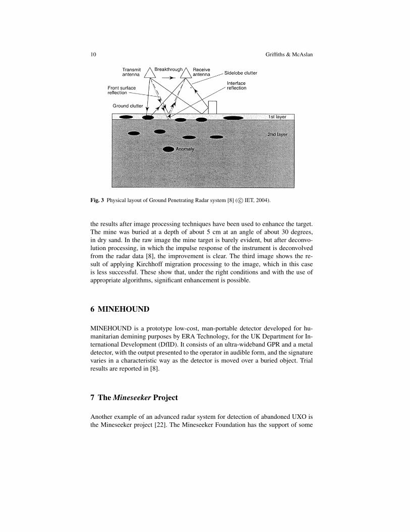
Fig. 3 Physical layout of Ground Penetrating Radar system [8] ( c© IET, 2004).
the results after image processing techniques have been used to enhance the target.The mine was buried at a depth of about 5 cm at an angle of about 30 degrees,in dry sand. In the raw image the mine target is barely evident, but after deconvo-lution processing, in which the impulse response of the instrument is deconvolvedfrom the radar data [8], the improvement is clear. The third image shows the re-sult of applying Kirchhoff migration processing to the image, which in this caseis less successful. These show that, under the right conditions and with the use ofappropriate algorithms, significant enhancement is possible.
6 MINEHOUND
MINEHOUND is a prototype low-cost, man-portable detector developed for hu-manitarian demining purposes by ERA Technology, for the UK Department for In-ternational Development (DfID). It consists of an ultra-wideband GPR and a metaldetector, with the output presented to the operator in audible form, and the signaturevaries in a characteristic way as the detector is moved over a buried object. Trialresults are reported in [8].
7 The Mineseeker Project
Another example of an advanced radar system for detection of abandoned UXO isthe Mineseeker project [22]. The Mineseeker Foundation has the support of some

Low frequency radar for buried target detection 11
Fig. 4 Oblique antipersonnel mine at an angle of 30 degrees: (a) B-scan of raw data; (b) aftermigration by deconvolution; (c) after Kirchhoff migration [8] ( c© IET, 2004).
Fig. 5 The MINEHOUND instrument (left), under test in Sarajevo (right) [8] ( c© IET, 2004).
12 Griffiths & McAslan
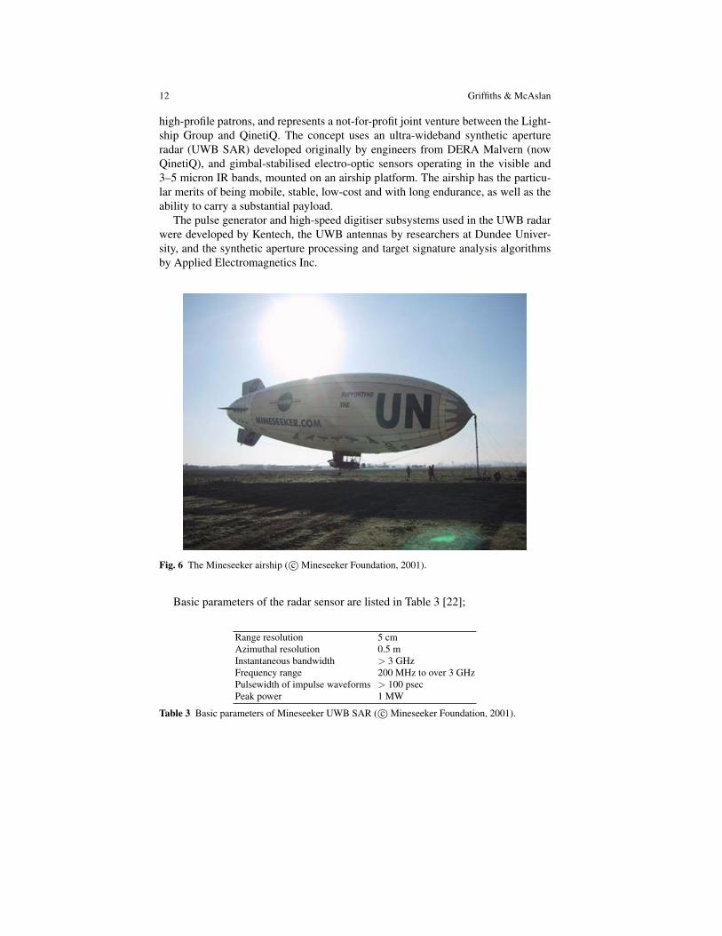
high-profile patrons, and represents a not-for-profit joint venture between the Light-ship Group and QinetiQ. The concept uses an ultra-wideband synthetic apertureradar (UWB SAR) developed originally by engineers from DERA Malvern (nowQinetiQ), and gimbal-stabilised electro-optic sensors operating in the visible and3–5 micron IR bands, mounted on an airship platform. The airship has the particu-lar merits of being mobile, stable, low-cost and with long endurance, as well as theability to carry a substantial payload.
The pulse generator and high-speed digitiser subsystems used in the UWB radarwere developed by Kentech, the UWB antennas by researchers at Dundee Univer-sity, and the synthetic aperture processing and target signature analysis algorithmsby Applied Electromagnetics Inc.
Fig. 6 The Mineseeker airship ( c©Mineseeker Foundation, 2001).
Basic parameters of the radar sensor are listed in Table 3 [22];
Range resolution 5 cmAzimuthal resolution 0.5 mInstantaneous bandwidth > 3 GHzFrequency range 200 MHz to over 3 GHzPulsewidth of impulse waveforms > 100 psecPeak power 1 MW
Table 3 Basic parameters of Mineseeker UWB SAR ( c©Mineseeker Foundation, 2001).

Low frequency radar for buried target detection 13
(a) (b)
(c) (d)
(e) (f)
(g) (h)
(i)
Fig. 7 Signatures of different targets obtained in trials with the Mineseeker UWB SAR: (a) surface-laid calibration sphere, HH polarisation; (b) surface-laid mortar round (inert), VV polarisation;(c) surface-laid RBL755 cluster bomb sub-munition (inert), VV polarisation; (d) above-groundPMR2a stake mine (inert), VV polarisation; (e) buried TMM1 metal anti-tank mine (inert), VVpolarisation; (f) buried RBL755 cluster bomb sub-munition (inert), HH polarisation; (g) buriedmortar round (inert), VV polaristion; (h) buried handgrenade (live), VV polarisation; (i) buriedPMR2a (live), VV polarisation ( c©Mineseeker Foundation, 2001).
14 Griffiths & McAslan
It has been demonstrated in trials that different mine targets have characteristicsignatures, so different mine types may be distinguished from each other and fromother false alarm debris (Figure 7). These examples also show the information thatmay be obtained from the polarimetric signatures of mines and other UXO, thoughin practice the additional hardware complication of a polarimetric radar makes thesetechniques very difficult.
MINESEEKER’s coverage rate (in terms of location and delineation) of morethan 100 square metres per second is claimed, in contrast to 20 to 50 square metresper day by manual demining.
The preceding are just two examples of practical GPR systems; many more aredescribed in [8].
8 Management of humanitarian demining programmes
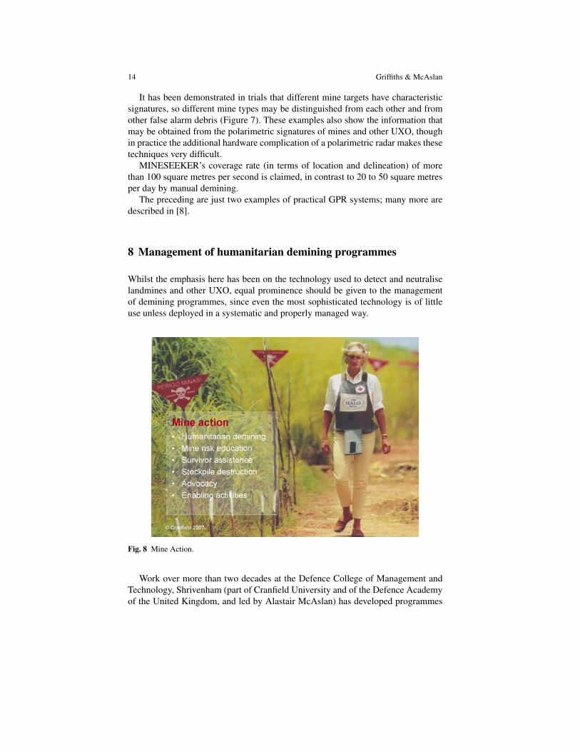
Whilst the emphasis here has been on the technology used to detect and neutraliselandmines and other UXO, equal prominence should be given to the managementof demining programmes, since even the most sophisticated technology is of littleuse unless deployed in a systematic and properly managed way.
Fig. 8 Mine Action.
Work over more than two decades at the Defence College of Management andTechnology, Shrivenham (part of Cranfield University and of the Defence Academyof the United Kingdom, and led by Alastair McAslan) has developed programmes
Low frequency radar for buried target detection 15
in the management of humanitarian demining, and earlier this year received theQueen’s Anniversary Prize for Higher and Further Education, from Her Majesty theQueen, for this work.
‘The management of mine action at the national level is, essentially, about ensur-ing that programmes, projects and day-to-day mine action activities are carried outeffectively, efficiently and safely. This involves defining the requirements throughassessment missions and site surveys, prioritising requirements, developing plans,securing funding, implementing projects and confirming that the requirements havebeen met’ [17].
‘Resilience’ may be defined as understanding the risks to nations and organisa-tions from factors as diverse as terrorism, natural disasters, health pandemics and ITfraud, and hence firstly being able to minimise the risks and effects, and secondlyensuring that the organisation is able to recover as quickly as possible. Deminingtherefore represents one specific aspect of Resilience.
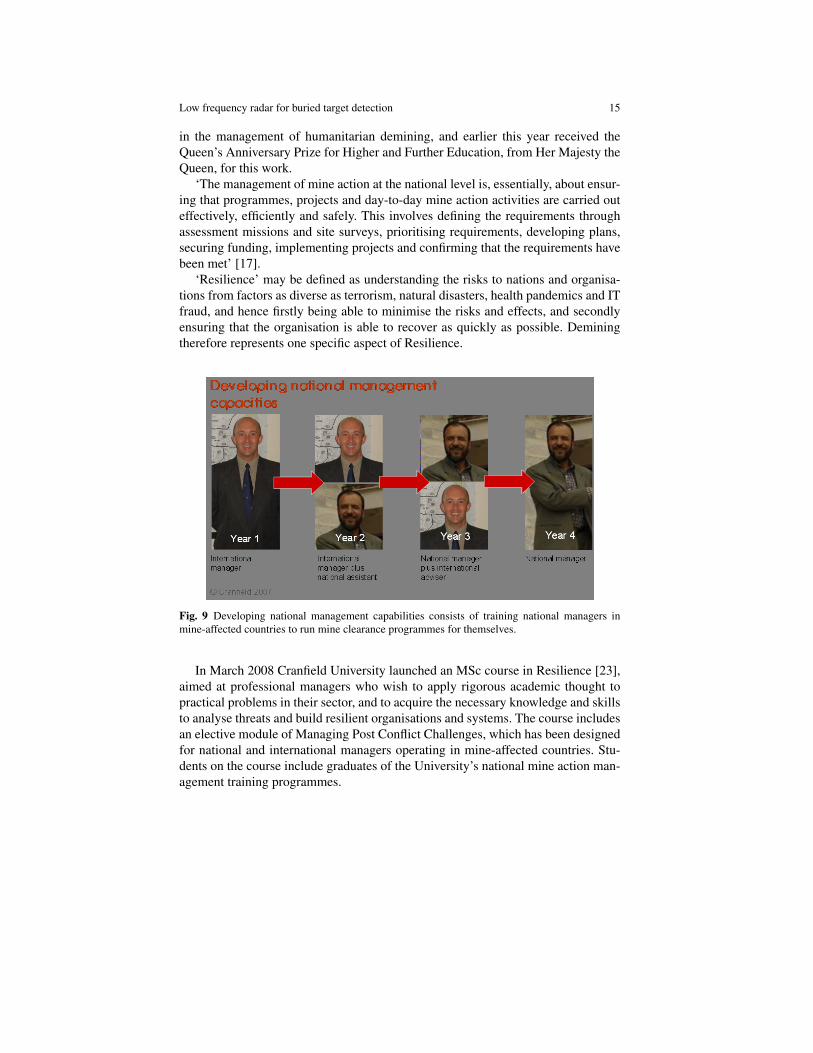
Fig. 9 Developing national management capabilities consists of training national managers inmine-affected countries to run mine clearance programmes for themselves.
In March 2008 Cranfield University launched an MSc course in Resilience [23],aimed at professional managers who wish to apply rigorous academic thought topractical problems in their sector, and to acquire the necessary knowledge and skillsto analyse threats and build resilient organisations and systems. The course includesan elective module of Managing Post Conflict Challenges, which has been designedfor national and international managers operating in mine-affected countries. Stu-dents on the course include graduates of the University’s national mine action man-agement training programmes.

16 Griffiths & McAslan
9 Conclusions
All of the foregoing has attempted to show first of all the extreme nature of theUXO detection and disposal problem. Many millions of landmines and other typesof ordnance have been deployed in conflicts, with few records of what has been laidand where. Not only do such weapons cause injury and death to innocent civilians,but also they deny the use of substantial areas of land for agricultural and other eco-nomic purposes, which may be critical in countries where the threshold of povertyis already low.
Low-frequency ground-penetrating radar represents one of a number of sen-sors that may be deployed to detect such targets. It is important to understand thestrengths and weaknesses of radar techniques for these purposes, and the synergywith other types of sensor. Under favourable (i.e. dry) ground conditions and atrelatively low radar frequencies penetration to significant depths can be obtained.However, low frequencies are unable to support wide radar bandwidths, so it is dif-ficult to obtain high resolution at the same time as significant penetration.
Whilst such sensors must always respect the laws of physics, improvements inRF hardware, in digital processing hardware and in processing algorithms mean thatsteady advances will continue to be made. One promising area is in the complemen-tarity of other types of sensor and hence of data and image fusion techniques tobetter exploit the strengths of each.
Acknowledgments
We express our thanks to Taz Greyling and all other members of the HumanitarianResilience Group at DCMT, Cranfield University, Shrivenham, and to David Danielsof ERA Technology and Chris Baker of UCL for reading and commenting on earlydrafts of this manuscript.
References
1. Aryanfar, F. and Sarabandi, K.: Through wall imaging at microwave frequencies using space-time focusing. IEEE Intl. Antennas and Propagation Symposium 3, 3063–3066 (20-25 June2004)
2. Benjamin, R., Hilton, G., Litobarski, S., McCutcheon, E. and Nilavalan, R.: ‘Post-detectionsynthetic near field focusing in radar or sonar’. Electronics Letters. 35(8), 664–666 (15 April1999)
3. Bottigliero, Ilaria: 120 Million Landmines Deployed Worldwide: Fact or Fiction. FondationPro Victimis, Geneve (2000)
4. Bridgeland, T. and Morgan, A.: Tunnel-master and Arsonist of the Great War: the Norton-Griffiths Story. Pen and Sword Books (2003)
5. Julius Caesar. De Bello Gallico, p191

Low frequency radar for buried target detection 17
6. Crisp, G.N. and Bishop, P.K.:‘The Mineseeker airship project’. In: Daniels, D.J. (ed.) GroundPenetrating Radar, second edition, IET Radar, Sonar and Navigation Series, ISBN 0 86341360 9, pp534–539. Springer, Heidelberg (2004)
7. Croll, M.: The History of Landmines. Pen and Sword Books (1998)8. Daniels, D.J. (ed.): Ground Penetrating Radar, second edition, IET Radar, Sonar and Naviga-
tion Series, ISBN 0 86341 360 9 (2004)9. EUREL International Conference on Detection of Abandoned Landmines (Edinburgh, Octo-
ber 1996); Second EUREL International Conference on Detection of Abandoned Landmines(Edinburgh, October 1998)
10. Griffiths, H.D. and Baker, C.J.: ‘Fundamentals of tomography and radar’. In: NATO Ad-vanced Study Institute Advances in Sensing with Security Applications, Il Ciocco, Italy, 17-30 July 2005, ISBN 1-4020-4286-8. Springer (2005)
11. Heald, G.J. and Griffiths, H.D.: ‘A review of underwater detection techniques and their ap-plicability to the land mine problem’. In: Proc. Second EUREL International Conference onThe Detection of Abandoned Landmines, Edinburgh, IEE Conf. Publ. No. 458, pp173–176,12-14 (October 1998)
12. Heliere, F., Lin, C-C., Corr, H. and Vaughan, D.: ‘Radio Echo Sounding of Pine IslandGlacier, West Antarctica and analysis of feasibility from space’. In: IEEE Trans. Geoscienceand Remote Sensing, pp2573–2582 (Aug. 2007)
13. Lin-Ping Song, Chun Yu and Qing Huo Liu: ‘Through-wall imaging (TWI) by radar: 2-Dtomographic results and analyses’. IEEE Trans. Geoscience and Remote Sensing Pura. Appl.43(12), pp2793–2798 (Dec. 2005)
14. McAslan, A. and Bryden, A.: ‘Mine Action Equipment: Study of Global Operational Needs’.Geneva International Centre for Humanitarian Demining. Geneva (June 2002)
15. McAslan, A. and Bryden, A.: ‘Study of Capability Shortfalls and Equipment Needs in South-east Europe’. European Commission (October 2000)
16. McAslan, A. and Goslin, B.: ‘The Mine Action Environment’. Pearson Custom Publishing(August 2004)
17. McAslan, A. and Greyling, T.: ‘Humanitarian Resilience: the need to develop sustainablenational capacities through education and training’. Principal’s Lecture, DCMT Shrivenham(5 December 2007)
18. Morrow, I.L. and Van Genderen, P.: ‘Effective imaging of buried dielectric objects’. IEEETrans. Geoscience and Remote Sensing. 40(4), pp943–949 (2003)
19. Sabath, F., Mokole, E. and Sammadar, S.N.: ’Definition and classification of ultra-widebandsignals and devices’. Radio Science Bulletin. 313, pp10–26 (June 2005)
20. http://www.darpa.mil/baa/baa06-04.html21. http://www.mineseeker.com/22. http://www.cranfield.ac.uk/students/courses/page1809.jsp