Performance EvaluationPerformance Evaluation of Buried ... Michele.pdf · Performance...
29
Performance Evaluation Performance Evaluation Performance Evaluation Performance Evaluation of Buried Pipe Installation of Buried Pipe Installation Preliminary Results Preliminary Results Preliminary Results Preliminary Results Michele Barbato Michele Barbato Assistant Professor Assistant Professor Dept. of Civil and Environmental Engineering Dept. of Civil and Environmental Engineering Louisiana State University, Baton Rouge Louisiana State University, Baton Rouge 2009 Louisiana Transportation Conference 2009 Louisiana Transportation Conference Baton Rouge, February 10, 2009 Baton Rouge, February 10, 2009
Transcript of Performance EvaluationPerformance Evaluation of Buried ... Michele.pdf · Performance...
Performance EvaluationPerformance EvaluationPerformance Evaluation Performance Evaluation of Buried Pipe Installationof Buried Pipe Installation
Preliminary ResultsPreliminary ResultsPreliminary ResultsPreliminary Results
Michele BarbatoMichele Barbato
Assistant ProfessorAssistant ProfessorDept. of Civil and Environmental EngineeringDept. of Civil and Environmental Engineeringp f g gp f g g
Louisiana State University, Baton RougeLouisiana State University, Baton Rouge
2009 Louisiana Transportation Conference2009 Louisiana Transportation ConferenceBaton Rouge, February 10, 2009Baton Rouge, February 10, 2009
OutlineOutline
• Problem Statement• Methodologygy• Finite Element Simplified Cross‐Section Model• Considered Modeling and PerformanceConsidered Modeling and Performance Parameters
• Performance Sensitivity StudyPerformance Sensitivity Study• Validation of Installation Requirements for Realistic Implementation SituationsRealistic Implementation Situations
• Main results and preliminary recommendationsrecommendations
• Ongoing and Future Studies
Problem StatementProblem StatementMotivations: • Buried pipe performance and reliability is not
fully addressed by current specifications • New competing materials (PVC, HDP)
Objectives:Determine effects of geometric and mechanicalDetermine effects of geometric and mechanical parameters on soil-structure interaction developed in buried pipe installationin buried pipe installation
Scope:R i l b i f i i f i iRational basis for revision of current provisions on buried pipe installation in Louisiana and USA.
MethodologyMethodology• The soil-structure interaction between pipe
and soil is studied using the finite element method.
• Performance measures are defined fromPerformance measures are defined from finite element response quantities.
P i di f d diff• Parametric studies are performed on different geometries, materials, configurations, natural
il i isoil situations
• Analysis is focused on performance y psensitivity to design variables
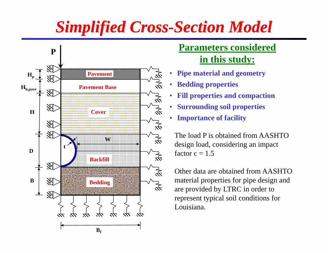
Simplified CrossSimplified Cross--Section ModelSection ModelParameters considered
• Pipe material and geometry
Parameters considered in this study:
P
PavementHp
• Bedding properties• Fill properties and compaction• Surrounding soil properties
CH
Pavement BaseHb,pave
g p p• Importance of facility
CoverH
W The load P is obtained from AASHTO d i l d id i i t
BackfillD
t design load, considering an impact factor c = 1.5
Other data are obtained from AASHTO BeddingB material properties for pipe design and
are provided by LTRC in order to represent typical soil conditions for Louisiana
Bf
Louisiana.
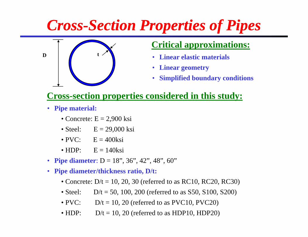
CrossCross--Section Properties of PipesSection Properties of PipesCritical approximations:
D tCritical approximations:• Linear elastic materials• Linear geometry
Cross-section properties considered in this study:
• Simplified boundary conditions
• Pipe material: • Concrete: E = 2,900 ksi• Steel: E = 29,000 ksi• PVC: E = 400ksi• HDP: E = 140ksi
• Pipe diameter: D = 18”, 36”, 42”, 48”, 60”p , , , ,• Pipe diameter/thickness ratio, D/t:
• Concrete: D/t = 10, 20, 30 (referred to as RC10, RC20, RC30)• Steel: D/t = 50 100 200 (referred to as S50 S100 S200)Steel: D/t 50, 100, 200 (referred to as S50, S100, S200)• PVC: D/t = 10, 20 (referred to as PVC10, PVC20)• HDP: D/t = 10, 20 (referred to as HDP10, HDP20)
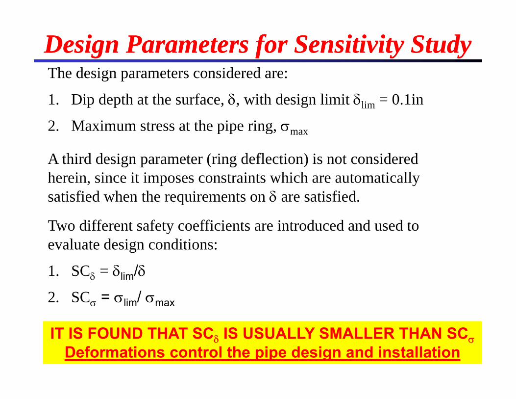
The design parameters considered are:Design Parameters for Sensitivity StudyDesign Parameters for Sensitivity StudyThe design parameters considered are:
1. Dip depth at the surface, , with design limit lim = 0.1in
2 Maximum stress at the pipe ring 2. Maximum stress at the pipe ring, max
A third design parameter (ring deflection) is not considered h i i it i t i t hi h t ti llherein, since it imposes constraints which are automatically satisfied when the requirements on are satisfied.
Two different safety coefficients are introduced and used toTwo different safety coefficients are introduced and used to evaluate design conditions:
1. SC = lim/1. SC lim/
2. SC = lim/ max
IT IS FOUND THAT SC IS USUALLY SMALLER THAN SCDeformations control the pipe design and installation
Surrounding soil stiffness (E )
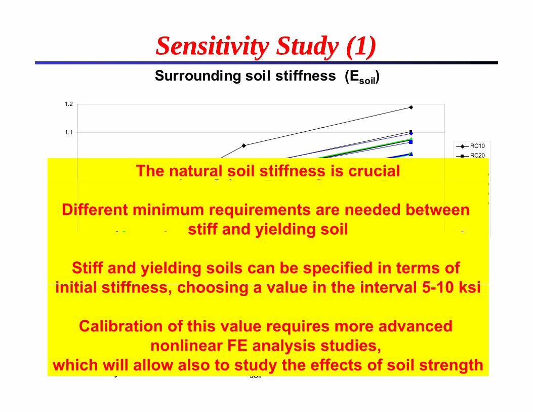
Sensitivity Study (1)Sensitivity Study (1)Surrounding soil stiffness (Esoil)
1.2
1
1.1
RC10RC20RC30HDP10The natural soil stiffness is crucial
0.8
0.9SC HDP20
PVC10PVC20S50S100S200
Different minimum requirements are needed between stiff and yielding soil
0.6
0.7
0 1 2 3 4 5 6 7 8 9 10 11
S200stiff and yielding soil
Stiff and yielding soils can be specified in terms of initial stiffness choosing a al e in the inter al 5 10 ksi0 1 2 3 4 5 6 7 8 9 10 11
Esoil (ksi)
Model properties: D = 60”; H = 12”; W = 18”; B = 6”
initial stiffness, choosing a value in the interval 5-10 ksi
Calibration of this value requires more advanced Efill = 30 ksi; Eb_pave = 45 ksi
Pavement type: Asphalt, h = 4”, hbase = 10”Sensitivity variable: soil stiffness Esoil = 1-5-10 ksi
nonlinear FE analysis studies, which will allow also to study the effects of soil strength
Trench width (W)
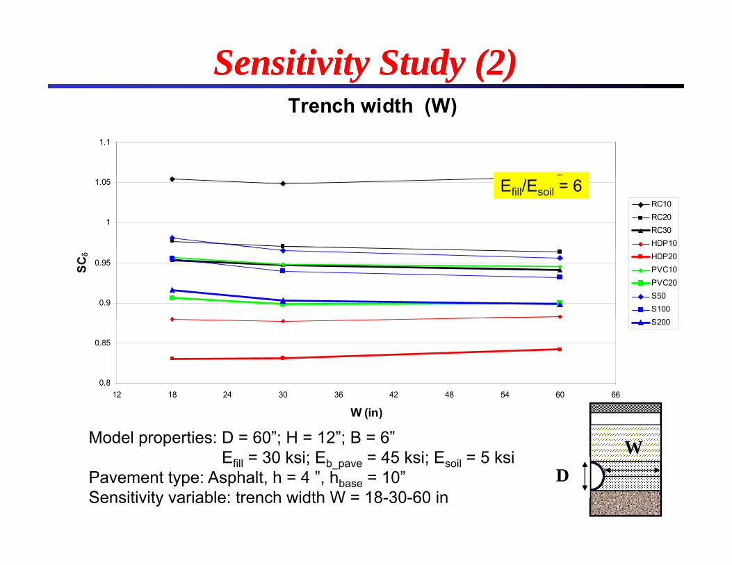
Sensitivity Study (2)Sensitivity Study (2)Trench width (W)
1.1
1
1.05
RC10RC20RC30HDP10
Efill/Esoil = 6
0.9
0.95SC HDP20
PVC10PVC20S50S100
0.8
0.85
S200
12 18 24 30 36 42 48 54 60 66
W (in)
Model properties: D = 60”; H = 12”; B = 6”Efill = 30 ksi; Eb = 45 ksi; E il = 5 ksi WEfill 30 ksi; Eb_pave 45 ksi; Esoil 5 ksi
Pavement type: Asphalt, h = 4 ”, hbase = 10”Sensitivity variable: trench width W = 18-30-60 in
D
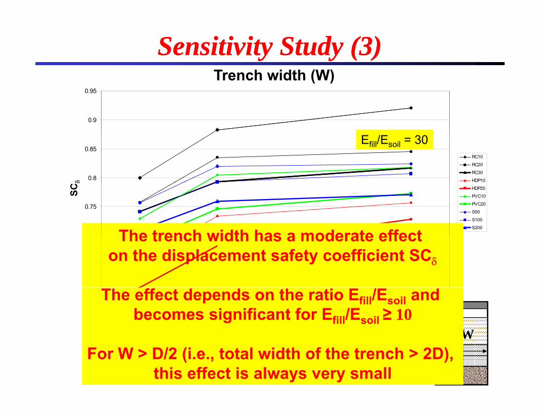
Trench width (W)Sensitivity Study (3)Sensitivity Study (3)
0.9
0.95
Trench width (W)
0.8
0.85RC10
RC20
RC30
HDP10
Efill/Esoil = 30
0 7
0.75
HDP20
PVC10
PVC20
S50
S100
S200
SC
The trench width has a moderate effect0.65
0.7 The trench width has a moderate effect on the displacement safety coefficient SC
0.612 18 24 30 36 42 48 54 60 66
Model properties: D = 60”; H = 12”; B = 6”W (in)
W
The effect depends on the ratio Efill/Esoil and becomes significant for Efill/Esoil ≥ 10
Efill = 30 ksi; Eb_pave = 45 ksi; Esoil = 1 ksiPavement type: Asphalt, h = 4 ”, hbase = 10”Sensitivity variable: trench width W = 18-30-60 in
DFor W > D/2 (i.e., total width of the trench > 2D), this effect is always very small
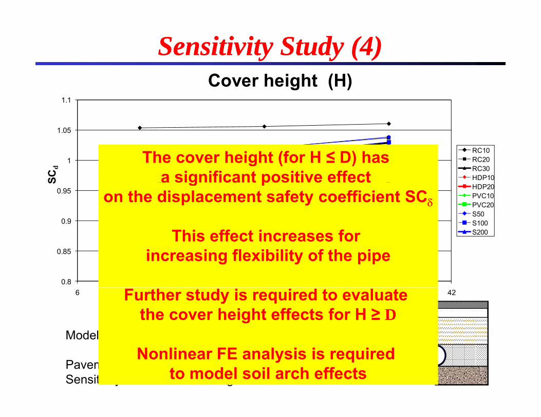
Co er height (H)
Sensitivity Study (4)Sensitivity Study (4)
1 05
1.1
Cover height (H)
1
1.05
SCd
RC10RC20RC30HDP10
The cover height (for H ≤ D) has a significant positive effect
0.9
0.95
S
HDP20PVC10PVC20S50S100S200
a significant positive effect on the displacement safety coefficient SC
This effect increases for
0.8
0.85
This effect increases for increasing flexibility of the pipe
6 12 18 24 30 36 42H (in)
Model properties: D = 60”; W = 18”; B = 6” H
Further study is required to evaluate the cover height effects for H ≥ D
p p ; ;Efill = 30 ksi; Eb_pave = 45 ksi; Esoil = 5 ksi
Pavement type: Asphalt, h = 4”, hbase = 10”Sensitivity variable: Cover height H = 12-24-36 in
DNonlinear FE analysis is required to model soil arch effects
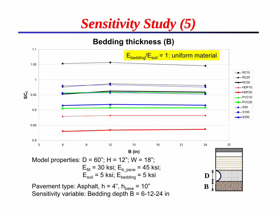
Bedding thickness (B)B ddi thi k (B)
Sensitivity Study (5)Sensitivity Study (5)g ( )
1.05
1.1
Ebedding/Esoil = 1: uniform material
Bedding thickness (B)
1
C
RC10RC20RC30HDP10HDP20
0.9
0.95
SC
HDP20PVC10PVC20S50S100S200
0.8
0.85
3 6 9 12 15 18 21 24 27
B (in)
Model properties: D = 60”; H = 12”; W = 18”;Efill = 30 ksi; Eb_pave = 45 ksi; E 5 ksi E 5 ksi DEsoil = 5 ksi; Ebedding = 5 ksi
Pavement type: Asphalt, h = 4”, hbase = 10”Sensitivity variable: Bedding depth B = 6-12-24 in
DB
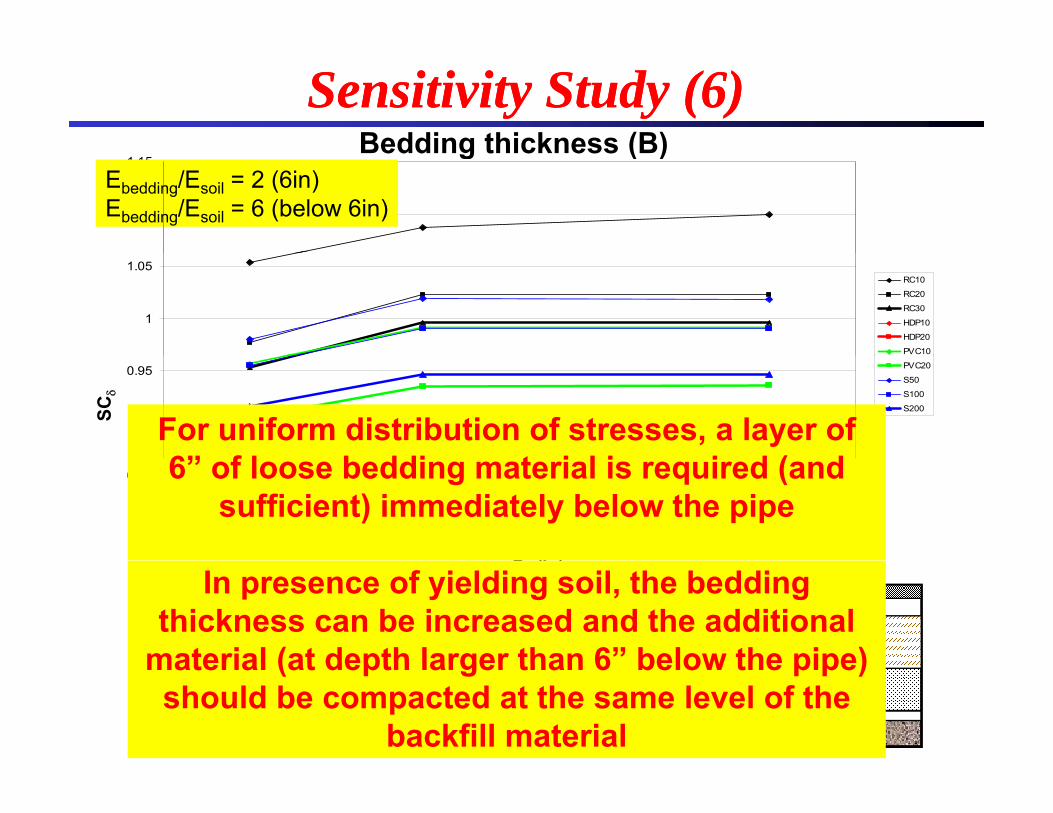
Bedding thickness (B)Sensitivity Study (6)Sensitivity Study (6)
1.1
1.15
Ebedding/Esoil = 2 (6in)Ebedding/Esoil = 6 (below 6in)
Bedding thickness (B)
1
1.05RC10
RC20
RC30
HDP10
HDP20
PVC10
0.9
0.95 PVC20
S50
S100
S200SC
For uniform distribution of stresses, a layer of 6” f l b ddi t i l i i d ( d
0.8
0.85
3 6 9 12 15 18 21 24 27
B (i )
6” of loose bedding material is required (and sufficient) immediately below the pipe
Model properties: D = 60”; H = 12”; W = 18”;Efill = 30 ksi; Eb_pave = 45 ksi; E 5 ksi E 10 ksi
B (in)In presence of yielding soil, the bedding thickness can be increased and the additional
material (at depth larger than 6” below the pipe)Esoil = 5 ksi; Ebedding = 10 ksi
Pavement type: Asphalt, h = 4”, hbase = 10”Sensitivity variable: Bedding depth B = 6-12-24 in
DB
material (at depth larger than 6 below the pipe) should be compacted at the same level of the
backfill material
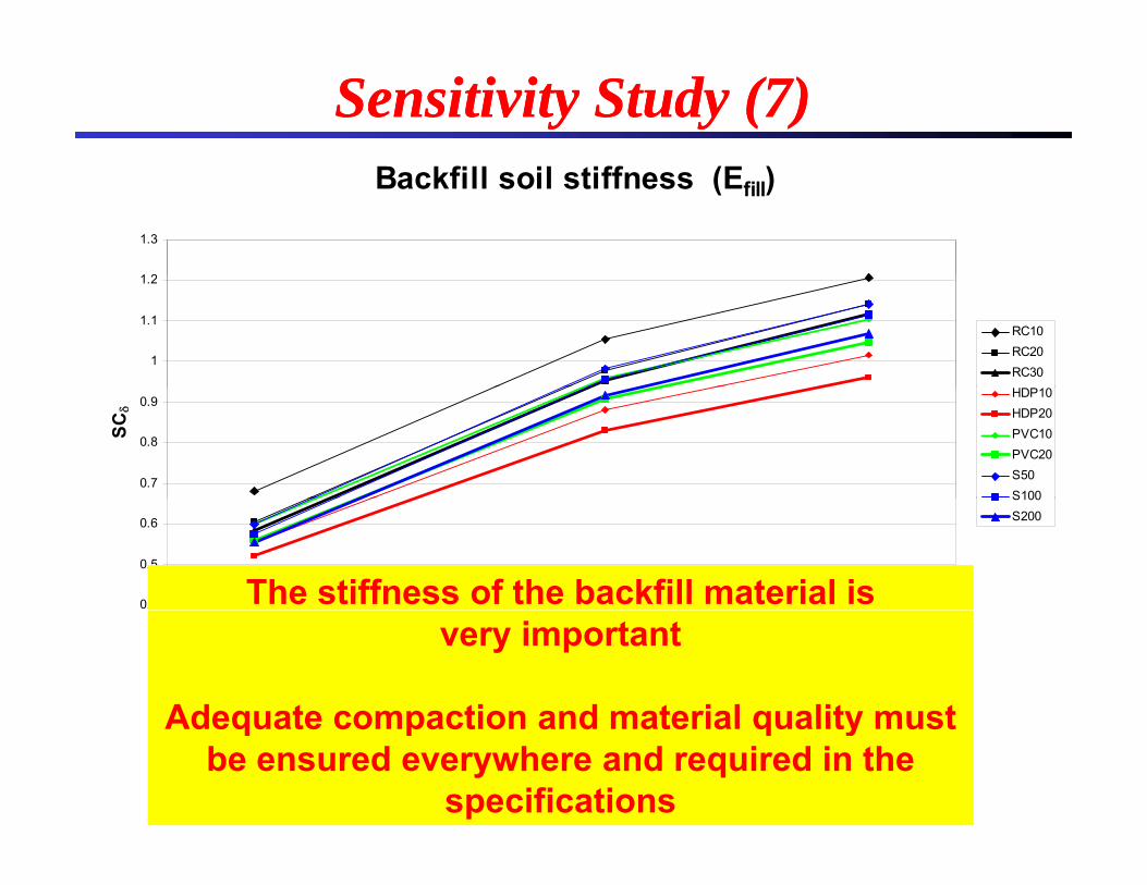
Sensitivity Study (7)Sensitivity Study (7)Backfill soil stiffness (Efill)
1 2
1.3
1
1.1
1.2
RC10RC20RC30
0.7
0.8
0.9
SC
HDP10HDP20PVC10PVC20S50S100
0.4
0.5
0.6
S100S200
The stiffness of the backfill material is 5 10 15 20 25 30 35 40 45 50
Efill (ksi)
Model properties: D = 60”; H = 12”; W = 18”; B = 6”E = 45 ksi; E = 5 ksi
very important
Adequate compaction and material quality mustEb_pave = 45 ksi; Esoil = 5 ksiPavement type: Asphalt, h = 4”, hbase = 10”Sensitivity variable: Backfill soil stiffness Efill = 10-30-45 ksi
Adequate compaction and material quality must be ensured everywhere and required in the
specifications
Road pavement typeRoad Pavement Type
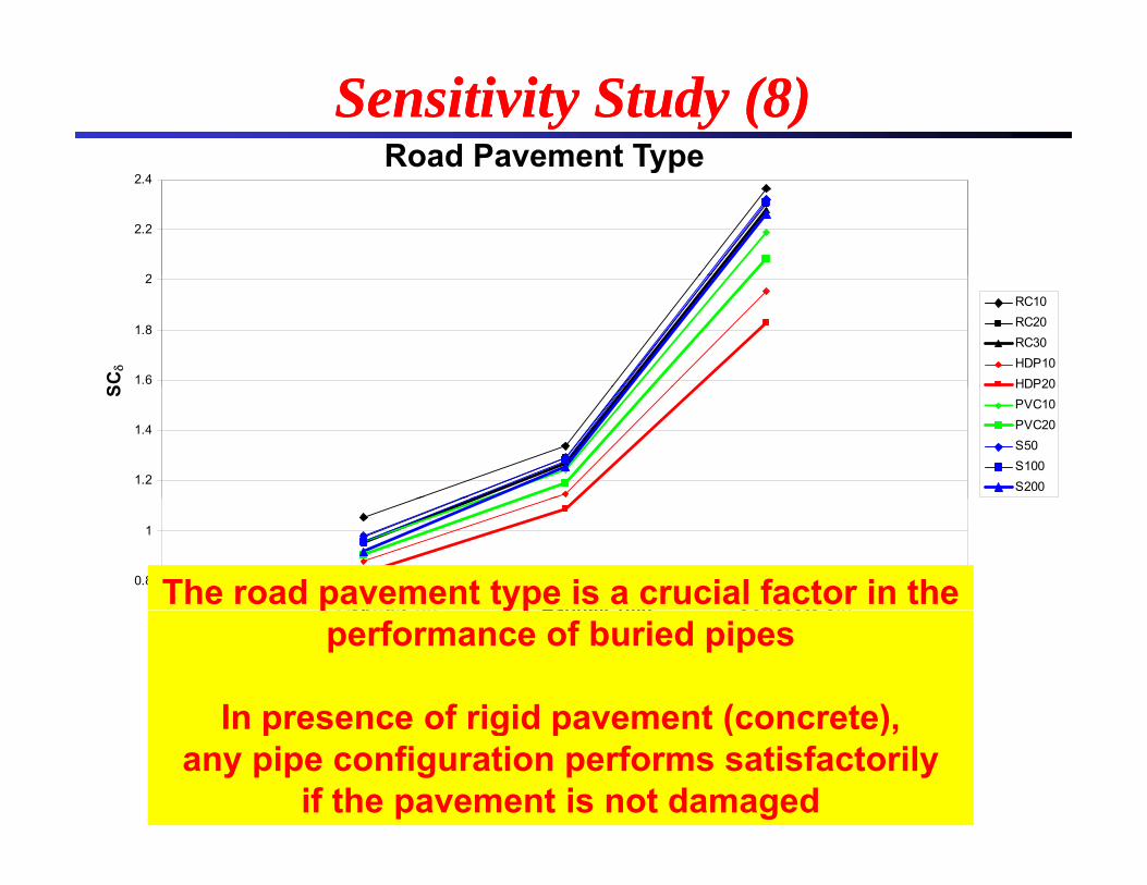
Sensitivity Study (8)Sensitivity Study (8)
2
2.2
2.4Road Pavement Type
1.6
1.8
2
SC
RC10RC20RC30HDP10HDP20
1.2
1.4
S HDP20PVC10PVC20S50S100S200
0.8
1
Asphalt 4in Concrete 8in Asphalt 10inThe road pavement type is a crucial factor in the sp a t Co c ete 8Asphalt 10in
Model properties: D = 60”; H = 12”; W = 18”; B = 6”Efill = 30 ksi; Eb_pave = 45 ksi; Esoil = 5 ksi
Sensitivity variable: Road pavement type
p ypperformance of buried pipes
In presence of rigid pavement (concrete)y p ypAsphalt, h = 4”, hbase = 10”Asphalt, h = 10”, hbase = 10”Concrete, h = 8”, hbase = 10”
In presence of rigid pavement (concrete), any pipe configuration performs satisfactorily
if the pavement is not damaged
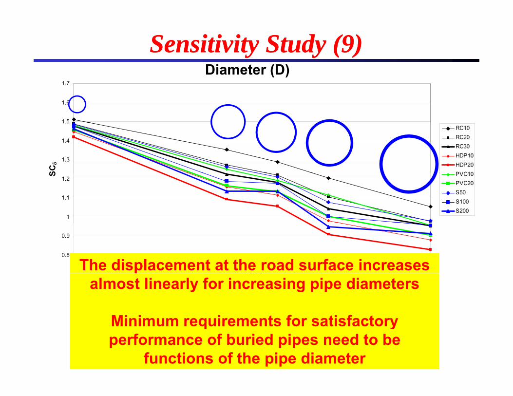
Diameter (D)Diameter (D)
Sensitivity Study (9)Sensitivity Study (9)
1.5
1.6
1.7
Diameter (D)
1.3
1.4
1.5
SC
RC10RC20RC30HDP10HDP20PVC10
1
1.1
1.2
S PVC10PVC20S50S100S200
0.8
0.9
18 24 30 36 42 48 54 60
D (i )The displacement at the road surface increases
D (in)
Model properties: H = 12”; W = 18”; B = 6”E = 30 ksi; E = 45 ksi; E = 5 ksi
palmost linearly for increasing pipe diameters
Minimum requirements for satisfactoryEfill = 30 ksi; Eb_pave = 45 ksi; Esoil = 5 ksiPavement type: Asphalt, h = 4”, hbase = 10”Sensitivity variable: Pipe diameter D = 18-36-42-48-60 in
Minimum requirements for satisfactory performance of buried pipes need to be
functions of the pipe diameter
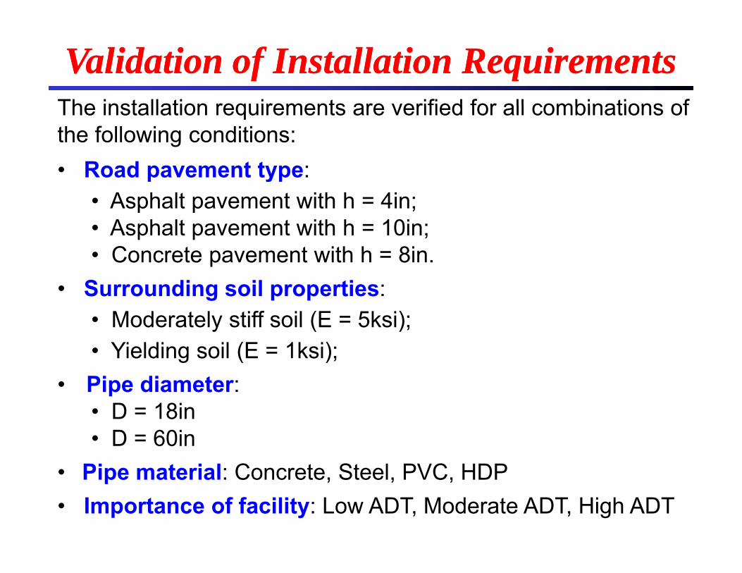
The installation requirements are verified for all combinations of
Validation of Installation RequirementsValidation of Installation RequirementsThe installation requirements are verified for all combinations of the following conditions: • Road pavement type: p yp
• Asphalt pavement with h = 4in;• Asphalt pavement with h = 10in;
Concrete pa ement ith h 8in• Concrete pavement with h = 8in.• Surrounding soil properties:
• Moderately stiff soil (E = 5ksi);Moderately stiff soil (E 5ksi); • Yielding soil (E = 1ksi);
• Pipe diameter:p• D = 18in• D = 60in
Pi t i l C t St l PVC HDP• Pipe material: Concrete, Steel, PVC, HDP• Importance of facility: Low ADT, Moderate ADT, High ADT
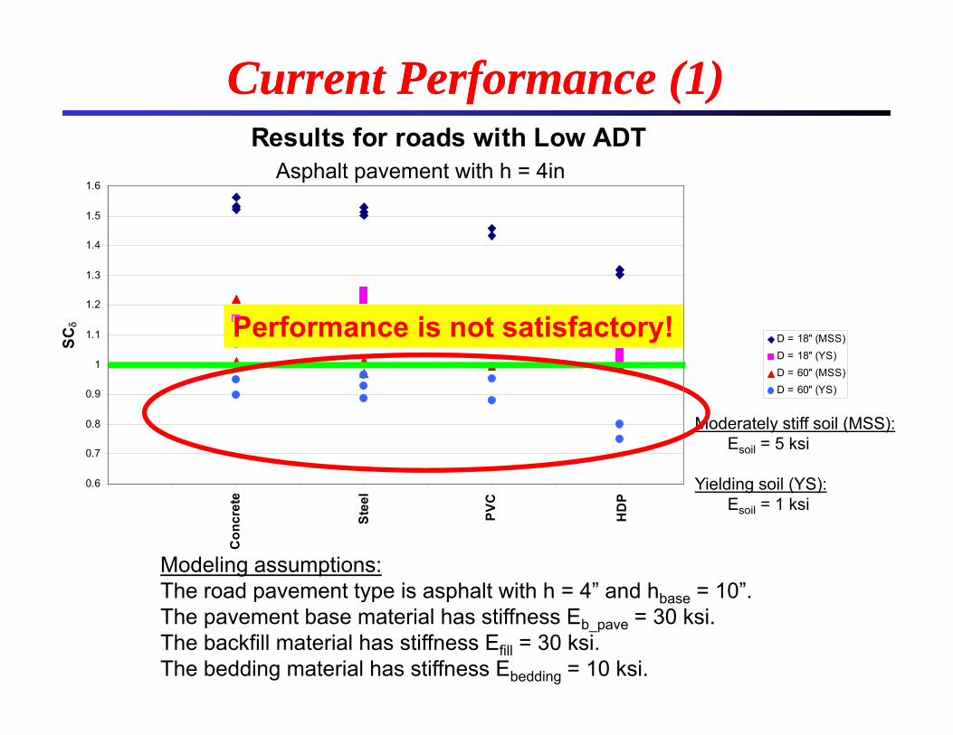
Results for roads with Low ADT
Current Performance (1)Current Performance (1)Results for roads with Low ADT
1.5
1.6Asphalt pavement with h = 4in
1.2
1.3
1.4
P f i t ti f t !
0.9
1
1.1
SC
D = 18'' (MSS)D = 18'' (YS)D = 60'' (MSS)D = 60'' (YS)
Performance is not satisfactory!
Moderately stiff soil (MSS):Esoil = 5 ksi
Yielding soil (YS):E il = 1 ksi
0.6
0.7
0.8
ete
eel
VC DP
Modeling assumptions:The road pavement type is asphalt with h = 4” and hbase = 10”.
Esoil 1 ksi
Con
cre
Ste
PV HD
p yp p baseThe pavement base material has stiffness Eb_pave = 30 ksi.The backfill material has stiffness Efill = 30 ksi. The bedding material has stiffness Ebedding = 10 ksi.
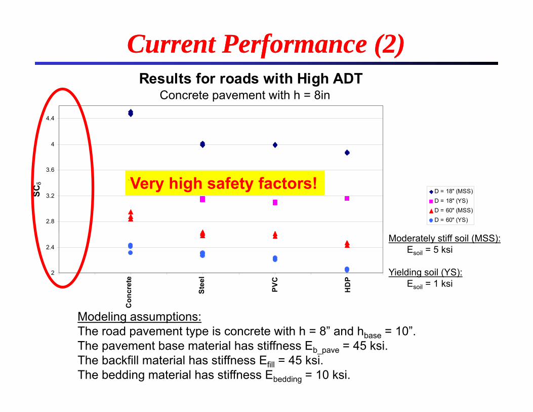
Results for roads with High ADT
Current Performance (2)Current Performance (2)Results for roads with High ADT
4.4
Concrete pavement with h = 8in
3.6
4
V hi h f t f t !
2.8
3.2SC
D = 18'' (MSS)D = 18'' (YS)D = 60'' (MSS)D = 60'' (YS)
Very high safety factors!
2
2.4
ete
eel
VC DP
Moderately stiff soil (MSS):Esoil = 5 ksi
Yielding soil (YS):E = 1 ksi
Con
cre
Ste
PV HD
Modeling assumptions:The road pavement type is concrete with h = 8” and hbase = 10”.
Esoil = 1 ksi
p yp baseThe pavement base material has stiffness Eb_pave = 45 ksi.The backfill material has stiffness Efill = 45 ksi. The bedding material has stiffness Ebedding = 10 ksi.
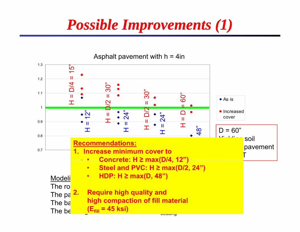
Possible Improvements (1)Possible Improvements (1)
1.3
Asphalt pavement with h = 4in
15”
1.1
1.2
As isH =
D/4
= 1
2 =
30”
= 30
”
60”
0.9
1Increasedcover
D = 60”
H
H =
D/2
H =
D/2
=
H =
D =
6
H =
12”
H =
24”
H =
24”
8”
0.7
0.8
rete
teel
PVC
HD
P
D = 60Yielding soilFlexible pavementLow ADT
H H H
H =
48
Recommendations:1. Increase minimum cover to
• Concrete: H ≥ max(D/4 12”)
Con
cr S P H
Modeling assumptions:The road pavement type is asphalt with h = 4” and hbase = 10”.
• Concrete: H ≥ max(D/4, 12 )• Steel and PVC: H ≥ max(D/2, 24”)• HDP: H ≥ max(D, 48”)
p yp p baseThe pavement base material has stiffness Eb_pave = 45 ksi.The backfill material has stiffness Efill = 45 ksi. The bedding material has stiffness Ebedding = 10 ksi.
2. Require high quality and high compaction of fill material(Efill = 45 ksi)
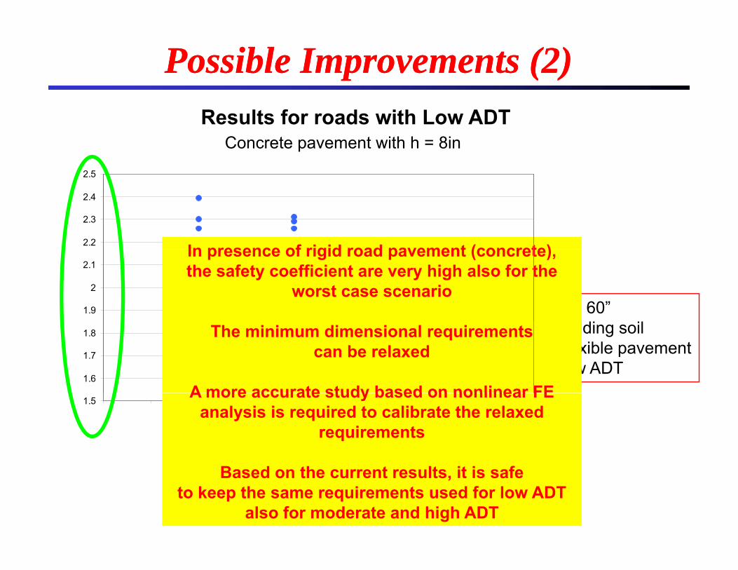
Possible Improvements (2)Possible Improvements (2)
Concrete pavement with h = 8inResults for roads with Low ADT
2.5
2.2
2.3
2.4
In presence of rigid road pavement (concrete)
1.9
2
2.1
D = 60”
In presence of rigid road pavement (concrete), the safety coefficient are very high also for the
worst case scenario
1.6
1.7
1.8 Yielding soilFlexible pavementLow ADT
The minimum dimensional requirements can be relaxed
A more accurate study based on nonlinear FE1.5
Con
cret
e
Stee
l
PVC
HD
P
A more accurate study based on nonlinear FE analysis is required to calibrate the relaxed
requirements
Based on the current results, it is safe to keep the same requirements used for low ADT
also for moderate and high ADT
1 P f i t f i d fl ti (di d th)
MainMain ResultsResults1. Performance in terms of maximum deflection (dip depth)
at the surface is often the most demanding requirement for buried pipe installation
2. The performance of the soil-structure system is crucially dependent on the road pavement type. For rigid pavement (concrete) pipe deformation is generally very small(concrete), pipe deformation is generally very small
3. Natural soil stiffness, backfill stiffness, cover height are very important
4. Bedding thickness and trench width have smaller effects on deformation. These effects depend on the ratio between the bedding and fill material stiffness and the natural soilthe bedding and fill material stiffness and the natural soil stiffness.
5. Pipe diameter, D, significantly affects surface p g ydisplacement. For D ≥ 48in and flexible pavement (asphalt), cover height should be function of D
Preliminary RecommendationsPreliminary Recommendations
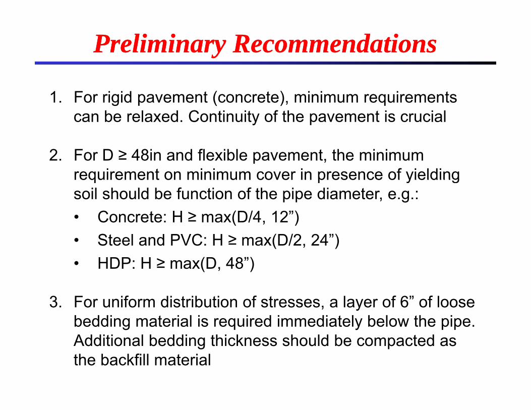
1. For rigid pavement (concrete), minimum requirements can be relaxed. Continuity of the pavement is crucial
2. For D ≥ 48in and flexible pavement, the minimum requirement on minimum cover in presence of yieldingrequirement on minimum cover in presence of yielding soil should be function of the pipe diameter, e.g.:• Concrete: H ≥ max(D/4, 12”)• Steel and PVC: H ≥ max(D/2, 24”)• HDP: H ≥ max(D, 48”)
3. For uniform distribution of stresses, a layer of 6” of loose bedding material is required immediately below the pipe. Additional bedding thickness should be compacted as the backfill material
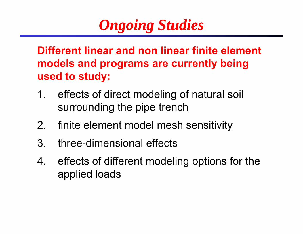
Ongoing StudiesOngoing StudiesDifferent linear and non linear finite element models and programs are currently being
d t t dused to study:1. effects of direct modeling of natural soil
surrounding the pipe trench
2. finite element model mesh sensitivity
3. three-dimensional effects
4 effects of different modeling options for the4. effects of different modeling options for the applied loads
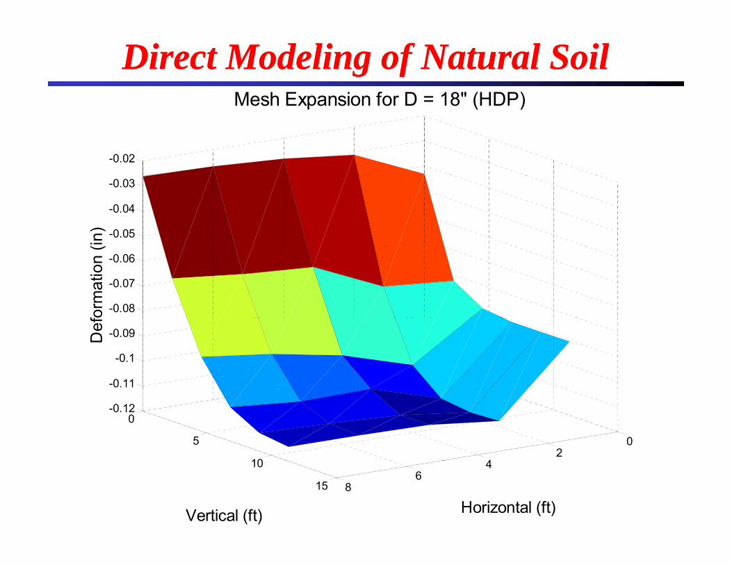
Mesh Expansion for D = 18" (HDP)
Direct Modeling of Natural Soil Direct Modeling of Natural Soil
-0.02
Mesh Expansion for D 18 (HDP)
-0.05
-0.04
-0.03
(in)
-0.08
-0.07
-0.06
form
atio
n (
-0.11
-0.1
-0.09Def
02
4
0
5
10
-0.12
46
8
10
15
Horizontal (ft)Vertical (ft)
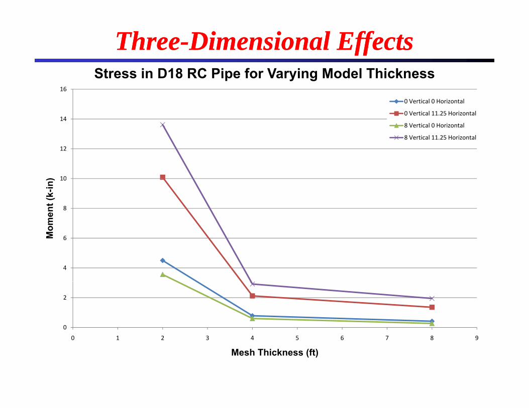
Stress in D18 RC Pipe for Varying Model Thickness
ThreeThree--Dimensional EffectsDimensional Effects
14
16
Stress in D18 RC Pipe for Varying Model Thickness
0 Vertical 0 Horizontal
0 Vertical 11.25 Horizontal
8 Vertical 0 Horizontal
10
12
)
8 Vertical 0 Horizontal
8 Vertical 11.25 Horizontal
8
10
omen
t (k-
in)
4
6Mo
0
2
0 1 2 3 4 5 6 7 8 9
Mesh Thickness (ft)

Suggested Model for Nonlinear Finite Suggested Model for Nonlinear Finite Element AnalysisElement Analysis
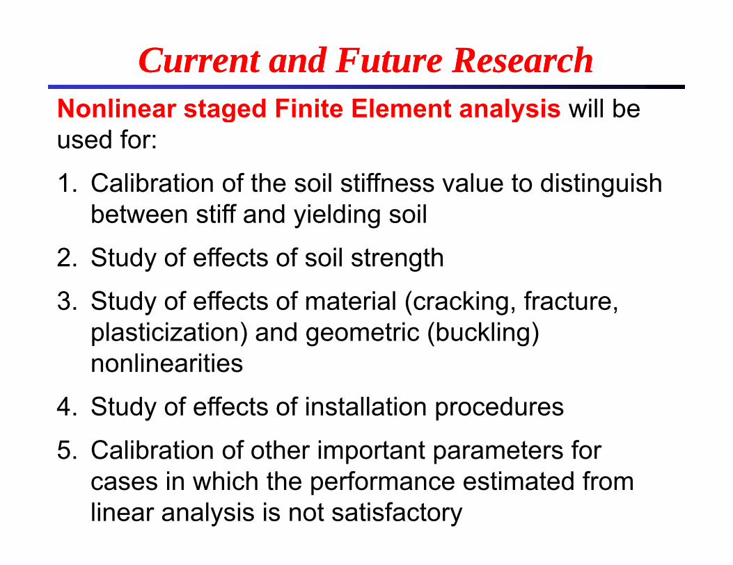
Nonlinear staged Finite Element analysis will be
Current and Future ResearchCurrent and Future ResearchNonlinear staged Finite Element analysis will be used for:
1 C lib ti f th il tiff l t di ti i h1. Calibration of the soil stiffness value to distinguish between stiff and yielding soil
2. Study of effects of soil strength
3. Study of effects of material (cracking, fracture, plasticization) and geometric (buckling) nonlinearities
4. Study of effects of installation procedures
5. Calibration of other important parameters for p pcases in which the performance estimated from linear analysis is not satisfactory
AcknowledgementsAcknowledgementsLA D t t f T t ti d D l t• LA Department of Transportation and Development
• Louisiana Transportation Research Center p(project 08-6GT)
• LA DOTD PIPE Committee• LA DOTD PIPE Committee
• Dr. Zhongjie “Doc” Zhang, Pavement and GeotechR h Ad i i t tResearch Administrator
Any opinions, findings, and conclusions or recommendations expressed in this material are those of the authors and do not necessarily reflect those of thematerial are those of the authors and do not necessarily reflect those of the sponsors.
Thank you!Thank you!Thank you!Thank you!Questions?Questions?