Lotus Service Notes Section HI -...
23
Page 1 Lotus Service Notes Section HI STEERING SECTION HI Sub-Section Page General Description HI.1 3 Power Steering Rack Operation HI.2 3 PAS Fluid Check & Refill Procedure HI.3 7 Steering Wheel HI.4 7 Ignition Barrel HI.5 10 Ignition Switch HI.6 11 Steering Column Assembly HI.7 11 Track Rod Ends & Rack Gaiters HI.8 15 Rack & Pinion Assembly Removal/Replacement HI.9 19 PAS Pump & Testing Procedure HI.10 20 PAS Pump Removal & Inspection HI.11 21 PAS Reservoir Removal/Replacement HI.12 23 Updated 12 th November 2012
Transcript of Lotus Service Notes Section HI -...

Page 1
Lotus Service Notes Section HI
STEERING
SECTION HI
Sub-Section Page
General Description HI.1 3
Power Steering Rack Operation HI.2 3
PAS Fluid Check & Refill Procedure HI.3 7
Steering Wheel HI.4 7 Ignition Barrel HI.5 10
Ignition Switch HI.6 11
Steering Column Assembly HI.7 11
Track Rod Ends & Rack Gaiters HI.8 15
Rack & Pinion Assembly Removal/Replacement HI.9 19
PAS Pump & Testing Procedure HI.10 20
PAS Pump Removal & Inspection HI.11 21 PAS Reservoir Removal/Replacement HI.12 23
Updated 12th November 2012

Page 2
Lotus Service Notes Section HI
Column and Rack Assembly
Upper column assembly
Intermediate column
Upper universal joint
Lower column Collapsible joint
Lower universal joint
Pinion shaft
Pinion end solid mountings
Rack and pinion assembly
Rubber sleeve Non-pinion end clamp
Tie rod Mounting bracket to chassis Alloy insert
Shim plate
Track rod
h62

Page 3
Lotus Service Notes Section HI
HI.1 - GENERAL DESCRIPTION
The power assisted steering system of the Evora comprises a column assembly, adjustable for height and reach, connected via two universal joints and an intermediate shaft, to a rack and pinion steering gear mounted on the chassis front subframe ahead of the front axle line. Power assistance is provided by an hydraulic pump mounted on the LH side of the engine, driven by the auxiliary belt, with an hydraulic reservoir located at the RH side of the engine bay. The pipes connecting the pump and reservoir to the rack assembly, are routed along the outside of the RH main chassis rail, within the body sill.
The column assembly comprises three sections, upper, intermediate and lower, articulated with two universal joints. The upper section is bolted to the chassis scuttle structure and provides for a steering wheel reach variation of 40 mm, and a vertical adjustment range of 43 mm. A clamping lever is positioned below the column, which is lowered to allow an adjustment to be made, and should be pushed fully upwards to clamp the setting before the car is driven. The intermediate column, like the upper, is telescopic, and in this instance allows for length compression of the column in the event of rack displacement in a vehicle collision. The short lower column connects to the steering rack pinion shaft.
The steering rack assembly consists of an alloy pinion housing/valve body, and a steel tube through which the rack is guided. The pinion housing features two lugs with solid alloy inserts, which bolt to an extruded alloy bracket, itself bolted to the subframe. The non-pinion end of the rack tube is clamped via a split rubber sleeve around the rack housing, to a second extruded bracket, again bolted to the subframe. Short ball jointed tie-rods from each end of the rack connect via length adjustable track rods, to forward facing steering arms integral with the forged steel front hub carriers, with outer pivot points positioned laterally to provide a 32% Ackermann effect, and vertically for a toe-out on bump characteristic. The rack and pinion assembly is geared to provide 47.4mm rack travel for one steering wheel revolution, with 2.86 turns needed from lock to lock.
Steering power assistance is sourced from a belt driven, vane type hydraulic pump, mounted at the right hand front of the engine. Pipework to and from the power rack assembly is routed within the RH body sill, with a fluid reservoir mounted at the RH rear of the engine bay. Some cars destined for hot climates are equipped with a befinned oil pipe cooler loop incorporated into the return line from rack to reservoir, and mounted ahead of, and at the base of the engine coolant radiator.
HI.2 - POWER STEERING RACK OPERATION
The steering rack assembly comprises the following major components:- a round section steel bar with rack teeth machined at one end.- an alloy pinion housing to support and contain the pinion shaft and hydraulic valve body assembly, and
also support the pinion end of the rack bar. - a steel tube pressed into the pinion housing to support the non-pinion end of the rack bar, and provide an
hydraulic cylinder for power operation of the rack.
The rack housing contains two seals, between which a piston on the rack bar operates to form two hy-draulic cylinders, each of which is linked to the valve body by a steel pipe. By using a pumped oil supply and a mechanism for creating a pressure differential between the two cylinders, a force can be applied to the piston and rack bar to provide steering assistance in either direction.
The valve body, which is integral with the pinion gear housing, contains three main elements:- an input shaft/valve rotor connected to the steering column;- a valve sleeve fixed to the pinion gear.- a torsion bar connecting the two;

Page 4
Lotus Service Notes Section HI
The steering column is clamped to splines on the top end of the rack input shaft, the lower end of which is machined to form a valve rotor, turning within the valve sleeve. The valve sleeve is fixed to the pinion gear and contains hydraulic ports which are controlled by the position of the rotor relative to the sleeve. The rotor and sleeve are connected by the torsion bar, the top end of which is secured inside the top end of the hollow input shaft (rotor), and the bottom end splined into the pinion gear (sleeve). The degree of twist of the torsion bar is determined by the force applied at the steering wheel, and is proportional to the loading at the front tyres. These forces tend to be highest when manoeuvering at low speed (e.g. parking) and result in the greatest angular displacement between valve rotor and sleeve.
The valve body incorporates 4 ports:- inlet from the engine driven pump;- outlet (return) to the reservoir;- connection to the right hand rack cylinder;- connection to the left hand rack cylinder.
Connection pin Splines to intermediate shaft Input shaft/valve rotor
Torsion bar
Hydraulic seal
Roller bearing Outlet to reservoir
Valve body To/from rack cylinder 1
Inlet from pump Sealing rings To/from rack cylinder 2
Valve sleeve
Torsion bar splined to sleeve/pinion Ball bearing/seal
Pinion gear h61

Page 5
Lotus Service Notes Section HI
Power Steering Schematic (RHD shown)
PAS reservoir
Low pressure line from reservoir to pump
Engine driven pump
Supply line to valve body
Low pressure return line to reservoir
Supply/return to RH cylinder
Valve body Supply/return to LH cylinder
Hydraulic seal
Track rod
Rack & pinion gear RH rack cylinder LH rack cylinder Sealed piston h62

Page 6
Lotus Service Notes Section HI
The schematic diagram below shows the principle of valve control, although in practice, six pockets are machined in the rotor and sleeve, and the valve system is repeated three times. The valve sleeve is provided with four sealing rings in order to divide the inlet and outlet feeds and connect with ports in the valve body, whilst allowing 360°rotation of the valve assembly.
The engine driven pump supplies oil at a controlled rate. A progressive restriction of this oil flow will cause the pressure to increase whilst the flow rate is maintained. Eventually, when the flow is completely restricted, the pressure will rise to the relief valve setting in the pump, causing oil to flow through the relief valve and re-circulate within the pump.
The hydraulic valve in the steering gear provides this restriction according to the force applied at the steering wheel and the loading on the front tyres. The valve is configured as 'open centre' such that when no torque is applied to the steering wheel, there is minimal restriction to the oil supply, resulting in low oil pressure and the freedom to flow to both rack cylinders and through the outlet port back to the reservoir. The pressure differential across the rack piston is zero.
When the steering is turned to the left against some resistance, the input shaft/rotor transmits the motion to the pinion gear/valve sleeve via the torsion bar, which twists in proportion to the effort applied at the wheel and the resistance at the tyres. Effort is high typically at slow vehicle speeds, or when parking. When the bar twists, the angular position of the rotor relative to the valve sleeve alters, with the result that the ports to cylin-der 1 become biased towards the pressurised supply, and the ports to cylinder 2 biased to the reservoir return port at low pressure. Hence a pressure differential is created within the rack housing, with higher pressure in cylinder 1 applying a force to the steering rack piston to assist the turn.
If the steering is turned hard against resistance, or the lock stop, the valve will completely close off the return path and cause delivery pressure from the pump to rise until the pressure relief valve in the pump opens; maximum assistance has been reached.
The ultimate degree to which the torsion bar is permitted to twist, is limited by mechanical contact between the input shaft and the pinion gear. This mechanism prevents the torsion bar being over stressed, defines the maximum level of assistance, and provides a safety back up in case of torsion bar failure; steering control would be retained, albeit with a small amount of lost motion.
RHD steering being Pressurised oil to turned to left Restricted return RH rack cylinder pathcausessupply Valvesleeve-fixedtopinion side pressure increase Angular position to rotor displacedduetoflexin Return to torsion bar reservoir
Oil supply from pump
Valve rotor/input shaft Torsionbar(connects (fixedtocolumn) valvesleevetorotor) Restricted return path causes supply side Oil returning from pressure increase h40a
LH rack cylinder

Page 7
Lotus Service Notes Section HI
HI.3 - PAS FLUID CHECK & REFILL PROCEDURE
(See sub-section HI.12 for PAS reservoir removal)
Recommended fluid: PAS or Automatic Transmission Fluid meeting Dexron IIICapacity: 1.5 litre
Fluid Level CheckThe PAS fluid reservoir is located at the right hand rear corner of the engine bay with the fluid level visible through the translucent material of the reservoir. The level of fluid will rise as the oil temperature warms during normal operation, and the best time to check the level (part of each routine service) is with the engine warm, immediately after a run.
With a warm engine, the level should be close to the 'MAX' mark, and if cold, close to the 'MIN'. Note that there are two sets of marks on the reservoir, with hot markings on the outboard side, and cold marks in the inboard side, the hot marks being at a slightly higher level. The fluid level will also drop slightly when the engine is running.
Under normal circumstances, the PAS fluid should not require any topping up, and a drop in level is likely to be an indication of a leak.
If topping up is required:Release the No. 8 x 3/4", flg. pozi screws (2) retaining 1. the RH air outlet side grille at the RH rear corner of the engine bay.
Remove the reservoir cap.2.
Using a suitable funnel to aid accurate pouring into 3. the reservoir, slowly add approved PAS fluid. Do not overfill.
Replace the cap securely, and refit the grille.4.
Fluid Change & BleedingIn the normal course of operation, it is not necessary to change the hydraulic fluid, only to check the level. If, however, the system becomes contaminated with dirt or other fluids, all pipework connections should be released and fluid expelled using low pressure air. Dispel fluid from the rack mechanism by turning the steering to each full lock. Dispel fluid from the pump by cranking the engine for a few moments with ignition disabled.
After draining the fluid, or after the loss of fluid during the course of repairs or hydraulic system disconnec-tion;- Fill the reservoir with an approved fluid.- Raise the front of the car and turn the steering wheel slowly from lock to lock several times. Top up fluid
level if necessary.- Lower the car, start the engine and idle for a few minutes, before turning the steering to full lock and hold-
ing for 3 seconds, then repeating for the opposite lock. Repeat this sequence several times.- Stop the engine and check the reservoir level. - Any foaming or emulsification of the oil is an indication of air in the system. Repeat the above procedure.
If symptoms persist, check for air/fluid leaks.
Updated 12th July 2012
RH air outlet grille
RHR clamshell
Innerclamshellpanel
PASreservoir cap
h74

Page 8
Lotus Service Notes Section HI
HI.4 - STEERING WHEEL
The alloy three spoke steering wheel features a flattened lower section to facilitate driver access, a leather trimmed rim, buttons for the cruise control (if fitted) and an airbag module which also serves as a press pad to operate the horns. The electrical supply for the steering wheel mounted equipment utilises a rotary coil as-sembly surrounding the column.
The wheel comprises a cast magnesium rim and spokes, to which is bolted a machined alloy hub, with a screw fixed alloy pressing to carry, via double sided tape, the cruise control buttons and/or trim.
To Remove Steering Wheel
WARNING: The following procedures must be followed in the order listed to temporarily disable the airbag system whilst working in the immediate vicinity of an airbag. Failure to follow this procedure could cause unintended airbag deployment, resulting in personal injury and unnecessary airbag sys-tem repairs.
i) Turn off the ignition.ii) Before disconnecting the battery, use the Lotus TechCentre to read any stored trouble codes.iii) Disconnect the negative (earth) lead from the battery and tape back to ensure that no contact with the
battery negative terminal can be made.iv) Wait for 30 seconds.v) Unclip the top part of the column shroud, then remove the lower part after releasing the three retaining
screws.vi) Locate and unplug the airbag harness from the rotary connector. Note that the connector socket is fitted
with 'shorting bars' which automatically interconnect the high and low terminals of the airbag to prevent unschedules deployment caused by a voltage differential.
1. On the reverse side of the steering wheel, release the two Torx head screws, accessible via holes in the plastic shroud around the steering wheel hub.
2. Withdraw the airbag module and disconnect the two airbag harness connectors and the two horn leads.
Airbag harness rotary connector
Airbag retaining screws
Column spacer
Rotary connector
Horn & airbag harness
Airbag/horn assembly
Steering wheel retaining bolt Cruise control
harness
Updated 3rd November 2010

Page 9
Lotus Service Notes Section HI
WARNING: When carrying a live airbag module, make sure the bag and trim cover are pointed away from you. In case of an accidental deployment, the bag will then deploy with minimal chance of injury. When placing a live airbag module on a bench or other surface, always face the bag and trim cover upwards, away from the surface. This is necessary so that a free space is provided to allow the airbag to expand in the unlikely event of accidental deployment.
CAUTION: An aluminium spacer washer is fitted between the steering wheel boss and the column upper thrust bearing to ensure that any axial load applied to the column via the steering wheel is transmitted to the upper bearing. If this washer is omitted on re-assembly following steering wheel removal, application of an end thrust to the upper steering column could result in displacement of an upper column intermediate bearing race. Such a consequence is not easily recovered, and could require column replacement.
To guard against this possibility, a service spacer tool T000T1519F is available to be used as a precau-tionary measure during column servicing. If the steering wheel of an Evora is to be removed, or other column servicing performed, first fit this spacer tool in the following manner:
a) Push down the adjustment release lever beneath the steering column, raise the column fully and pull the steering wheel fully rearwards.
b) From beneath the column, slide the Nylon spacer tool T000T1519F onto the inner column between the bearings of the upper column assembly. Feed the non-chamfered end in first, towards the rear, and then rotate the tool to sit on top of the column.
c) Push the steering wheel forwards to trap the tool in place and then lock the adjustment lever.
3. Unplug the cruise control harness and the airbag/horn harness from the rotary connector.
4. Ensure the wheels are pointing straight ahead, match mark the wheel to the column, and remove the steering wheel retaining bolt. Note that the wheel is located on a steep angle hexagonal taper on the column.
CAUTION: If excessive force is applied to either the steering wheel or column, the break-out in-serts securing the column to the fascia bracket may be disturbed, necessitating replacement of the complete column. If necessary, use an appropriate puller.
Non-chamfered end
Special Tool T000T1519F
REAR
Updated 3rd November 2010

Page 10
Lotus Service Notes Section HI
5. If necessary, remove the cruise control switches and trim by carefully prising away from the double sided tape fixing. Remove the 4 screws to release the cover from the wheel reverse side.
6. Before refitting a steering wheel, ensure that the aluminium spacer ring A132U0523F is fitted between the wheel hub and the column upper bearing. Some early cars may have been built erroneously with this spacer omitted.
7. Refit in reverse order to removal, but before fitting the steering wheel, it is essential to centralise the rotary connector, or the unit will be broken when lock is applied. Turn the connector fully clockwise until it tightens, and then turn back just over two turns until the red marker appears in the square window. Note that this instruction is printed on the rotary connector. Ensure the road wheels are pointing straight ahead and fit the steering wheel with the match marks aligned. Tighten the steering wheel retaining bolt to 50 Nm.
When fitting the jump harness for the cruise controls, ensure the cable is routed through the channel provided in the steering wheel carrier.
8. After re-assembly, check that the airbag tell tale lights for a few seconds with ignition, and then goes out. Reset column position to customer's preference.
Steering Wheel Alignment Ideally, the steering wheel should align in the straight running position, with the steering rack centralised and with equal track rod lengths. In practice, a minor compromise to track rod lengths may have to be made. To arrive at the optimum setting, proceed as follows: Note that only one splined joint in the steering system allows a choice of position, this being the connec-tion of the lower column to the rack pinion shaft.
1. Set the front wheel alignment to specification with equal track rod lengths (see sub-section CK.2).
2. With the wheels pointing straight ahead, fit the steering wheel on the column hexagonal taper in the straight ahead position, and secure with the retaining bolt, torque tightening to 50 Nm.
3. Road test the car and mark the actual 'straight ahead' position of the wheel which should deviate from the ideal position by less than 5°. If more than this, the lower column should be released from the rack pinion shaft and re-positioned on the splines before repeating the procedure.
4. Final steering wheel alignment is achieved by asymmetric adjustment of the track rods, retaining the overall toe-out setting.
Updated 3rd November 2010

Page 11
Lotus Service Notes Section HI
HI.5 - IGNITION LOCK BARREL
Removal.
1. Remove steering column shroud (see sub-section VE.10).
2. Do not remove ignition switch unless necessary (see cau-tions on sub-section HI.7).
3. Place key in ignition barrel and turn to position 'I'. 4. depress the spring pin accessible via a hole in the rear of
the housing, and withdraw the lock barrel.
Refitment.Is the reversal of removal, note: the ignition key must be positioned at ‘I' before the locating pin can be de-pressed to allow insertion back into the barrel housing. Ensure the pin is correctly engaged in the housing hole.
HI.6 - IGNITION SWITCH
Removal
1. Remove steering column shroud (see sub-section VE.10).
2. Do not remove lock barrel unless necessary (see cautions on sub-section HI.7)
2. Disconnect the wiring harness multiplug connector from the switch.
3. Depress the upper and lower switch locking tabs and with-draw the switch from the column housing.
Refitment.Is the reversal of removal, note: the inset drive within the ignition switch must be adjusted to match the position of the lock spindle before refitting onto the column housing.
locking tab
Lock barrel to ignition drive spindle
Updated 3rd November 2010
Spring pin
Pin locating hole

Page 12
Lotus Service Notes Section HI
HI.7 - STEERING COLUMN ASSEMBLY
The steering column assembly includes a two-piece upper inner column, consisting of two tubes ('A' up-per; 'B' lower) with a sliding splined joint to accommodate reach adjustment, articulated via a universal joint to a similarly constructed two-piece ('C' upper; 'D' lower) intermediate column, which allows for telescoping compression in the event of vehicle collision. A third, lower column ('E'), is articulated from the intermediate shaft via a second universal joint, and is splined directly to the rack pinion shaft.
The upper column assembly comprises a steel mounting bracket from which is hung a pivoted alloy carrier for the ball bearing race supporting the lower end (B) of the two-piece upper column.
The upper (steering wheel) end of the column (A) is supported in a steel tube outer column fitted with synthetic plain bushes. The outer column is fixed to the column mounting bracket via a cam operated clamp, which al-lows vertical and axial movement of the upper outer/inner column assembly, the inner column (A) being free to slide over the splines on the lower column (B).
The upper end of the assembly incorporates an alloy housing to accommodate the steering lock/ignition switch and top bearing.
The lower end of the upper column assembly is articulated via a universal joint to the intermediate column, which itself comprises an upper tube (C) splined over a lower shaft (D) to provide a telescopic length variation of approx. 50mm.
This feature allows for steering column length compression in the event of vehicle collision in order to reduce the potential for occupant injury. For a similar purpose, the mounting bracket for the upper column assembly is constructed in two parts, the forward part being rigidly secured to the scuttle beam, whereas the rearward part is retained to the beam only by open ended slots equipped with special 'break out' inserts. In the event of a heavy forward load being applied to the steering wheel, such as may occur in an accident, the rearward part of the bracket complete with upper column assembly is able to break free from the scuttle, pushing the column (B) through the lower bearing and collapsing the intermediate column. After any such occurence, the complete steering column assembly should be replaced. If, in any circumstances, an abnormal load is applied to the steering wheel or upper column assembly, the column shrouds should be removed and the 'break out' inserts carefully checked.
Updated 3rd November 2010
Upper column upper 'A' Steel mounting bracket Alloy bearing housing and lock mechanism
Intermediate column upper 'C' Pivot for upper column assembly
Intermediate column Upper universal joint lower 'D'
Telescopic crash joint
h63

Page 13
Lotus Service Notes Section HI
To Remove Steering Column Assembly
WARNING: The driver's airbag is housed in the hub of the steering wheel. Precautions need to be taken for personal safety when working with airbags and associated componentry. Do not attempt to remove the airbag, steering wheel or column without first referring to section WF.
1. Remove the steering wheel (see sub-section HI.4).
2. Remove the rotary connector (see sub-section WF.10).
3. Remove the fascia dash panel (see sub-section VE.7).
4. Release all wiring harness restraints from the column.
5. If necessary, remove the steering lock/ignition key barrel (see sub-section HI.5)
6. If necessary, remove the ignition switch (see sub-section HI.6)
CAUTION: If the lock barrel is removed, on no account should the position of the lock mechanism be disturbed, or irrepairable displacement of the mechanism may occur, necessitating replacement of the complete column assembly.
Lower universal joint & pinchbolts
Column mounting brackets
Steering angle sensor & bracket assembly
Dashboard scuttle beam
Column/footwell grommet
Steering angle sensor peg clamp
Mounting bracket frontfixings
Mounting bracket verticalfixings
Updated 19th April 2012

Page 14
Lotus Service Notes Section HI
7. Remove the front undertray and remove the pinch bolt securing the lower universal joint to the column. Match mark the joint and column
8. The column must be withdrawn complete with the two extruded alloy mounting brackets securing it to the scuttle beam. For each of these two brackets, release the single front fixing into the top surface of the scuttle beam, and the two rear fixings into the vertical face; all use threaded inserts in the chassis.
9. Withdraw the column assembly from the pinion shaft and through the steering angle sensor and fascia aperture. (See sub-section JL. - 15 for further information on the steering angle sensor).
To Fit Steering Column Assembly
Continue re-assembly in reverse order to removal with the following notes:
- Slide the toe board gaiter over the intermediate column during installation, and ensure that the steering angle sensor peg locates in the narrow slot in the hub of the steering sensor.
Align the match marks before engaging the column into the lower u/j. •If a new column is being fitted, note that the flat on the spline of the intermediate shaft must align with pinch bolt axis in the joint.
Torque tighten fixings as follows:•
- Column 'break out' fixings; 24 Nm- Column to forward fixing holes in extruded scuttle brackets; 24 Nm- Extruded brackets to scuttle; 24 Nm- Lower u/j pinch bolts; 25 Nm
Once the steering column is refitted it is essential to recalibrate the steering angle sensor using Lotus Techcentre. Once the correct vehicle by model type, year and market has been identified then select ABS > Guided routines > Steering angle sensor calibration.
Failure to calibrate the sensor could result in impaired traction control/Dynamic Performance Management funtionality and will illuminate the tell-tale light.
Fitting New Steering Column AssemblyIf a new column is being fitted, the steering angle sensor peg clamp must be transferred to the new
column, with the upper edge of the clamp positioned 29mm from the bottom face of the upper universal joint. Orientation is immaterial.
Aftersales service replacement steering column assemblies are now supplied with an ignition switch al-ready fitted and a plastic sleeve fitted into the lock barrel bore to minimise the risk of the lock mechanism being disturbed in transit or whilst being fitted to the vehicle
CAUTION: Even though the risk of lock mechanism becoming displaced is minimised with the ignition switch in situ, do not remove the plastic sleeve until you are ready to insert the lock barrel.
In the unlikey event that a steering column is supplied without an ignition switch follow the procedure shown on the next page:
VEHICLE QUALITY CONCERN
Orientation of steering column peg and steering angle sensor
Updated 19th April 2012

Page 15
Lotus Service Notes Section HI
a) With the plastic sleeve still in place use the lock spindle to turn the lock mechanism to position 1 (to match the features of the key lock barrel at this position see picture 1). At this position, the column is unlocked.
b) As a precaution, maintain a pulling action on the lock spindle from now until the lock barrel is securely installed.
c) Turn the plastic insert a quarter turn clockwise and withdraw. (Picture 2).
d) Fit the lock barrel (see sub-section H.I.5).
e) The lock spindle may now be released.
f) Fit the ignition switch (see sub-section H.I.6).
The column assembly is now safe to fit to onto the vehicle.
Updated 3rd November 2010
2
Correct alignment of lock spindle
Rotate plasticsleeve
1

Page 16
Lotus Service Notes Section HI
HI. 8 - TRACK ROD ENDS & RACK GAITERS
Front Wheel AlignmentAlignment is measured either by the angle the front wheels make with the vehicle's longitudinal axis, or
the difference in dimension between the wheel rim to wheel rim measurement at the front and rear of the wheel at hub centre height. The wheels are said to 'toe-in' when the wheel paths converge ahead of the vehicle, and 'toe-out' when they diverge. Wheel alignment is designed to vary with both steering angle (Ackermann; to minimise low speed, tight turn tyre scrub) and suspension travel (bump steer; to provide consistent handling) and should be measured only 'straight ahead' at the specified mid-laden ride height.
Provision is made for the adjustment of front wheel alignment at the joint between the steering rack tie rods, which are ball jointed to the outboard ends of the rack, and the track rods which incorporate the outer ball joints ('track rod ends') which connect to the steering arms on the hub carriers.
The mid-laden ride height and alignment specification is detailed in sub-section CK.2.
Note that in order to preserve the required bump steer characteristic and steering symmetry, the effective length of each track rod must remain equal; compare dimensions and equalise if necessary before subsequently adjusting each track rod by a similar amount:
1 Slacken the rack gaiter outboard clips.
2 Hold the track rod using the flats provided, and slacken the locknut. Repeat for the opposite side.
3 Turn each track rod a similar amount. As a guide, turning both track rods by one quarter of a turn will alter overall toe-out by approx. 2.0 mm.
4 When adjustment is correct, hold each track rod and tighten the locknuts to 45 Nm. Tighten the rack gaiter clips.
CAUTION: When slackening or tightening the track rod locknuts, it is important that the torque reaction is re-sisted using the track rod flats, and that the ball joint itself is not allowed to be stressed.
Track Rod EndsThe track rod end ball joints are sealed for life and maintenance free. If replacement is required;
- Remove the ball pin nut and use a ball joint splitter tool to separate the joint from the steering arm.
- Unscrew the track rod from the steering rack tie rod, using the locknut as a refitment position guide.
- On re-assembly, tighten the ball joint to steering arm nut to 45 Nm, and set the front wheel alignment as detailed in sub-section CK.2.
Rack Gaiter
Racktierodflats
TrackrodflatsHub carriersteering arm Track rod locknut
Track rod end balljoint h64

Page 17
Lotus Service Notes Section HI
Steering Rack GaitersThe convoluted gaiters sealing each end of the steering rack housing to the tie rods, should be inspected
at service intervals and replaced immediately if found to be torn, cracked or otherwise damaged.
The ingress of dirt or water into the rack housing will cause rapid deterioration of the track rod inner ball joints, rack end bushes and rack and pinion mechanism, requiring replacement of the complete steering gear.
To replace a gaiter, remove the track rod (see above), release the gaiter clips, and slide the gaiter off the housing and tie rod. Check for consequent damage or wear and replace the steering gear assembly if neces-sary. Fit the new gaiter into position, and secure with new retaining clips.

Page 18
Lotus Service Notes Section HI
HI. 9 - RACK & PINION ASSEMBLY REMOVAL/REPLACEMENT
The steering rack assembly consists of an alloy pinion housing/valve body, and a steel tube through which the rack is guided. The pinion housing features two solid bushed lugs, which bolt to an extruded alloy bracket, itself secured to the subframe with four bolts threading into a tapping plate. Note that the only approved repairs or adjustments to the steering rack assembly are the replacement of the track rod ends, rack housing gaiters, and the pipes connecting the pinion housing to the rack body.
The RH (pinion) mounting bracket is packaged very close to the HVAC (Heater Ventilation Air Conditioning) unit. From ‘10MY VIN AH_10901 the HVAC unit was modified increasing its width and the RH mounting bracket was machined to accommodate the increased width.
Therefore if you are renewing the HVAC unit an any Evora prior to ‘10MY VIN AH_10901 with the latest level Aftersales replacement unit it will be necessary to also renew the RH (pinion) mounting bracket to the latest level for which the part number can be obtained in the Lotus Evora Service Parts List.
LH - Rack Side or RH - Pinion Side Steering Rack Mount Replacement
Remove steering rack - see procedure on following pages, 1.
Release M10 x 30 flanged headed bolts (4) retaining the RH mount or M10 x 30 flanged headed bolts (2) 2. retaining the LH mount to the lower wishbone longitudinal member of the front subframe.
Remove the mount(s) and collect spacer shims located betweens the mount and longitudinal member. 3.
To Refit/Renew
Is the reversal of removal.Fit mount and spacer shims to lower wishbone longitudinal member. -
Note: If the rack mounting plinths are removed from the front subframe, note that there are shim plates fitted
Steering rack
RH - Pinionside mountingmountng bracket
LH - Rackside mountingmountng bracket
Rack supportclamp
Rack supportinsert
Updated 12th November 2012
Page 19
Lotus Service Notes Section HI
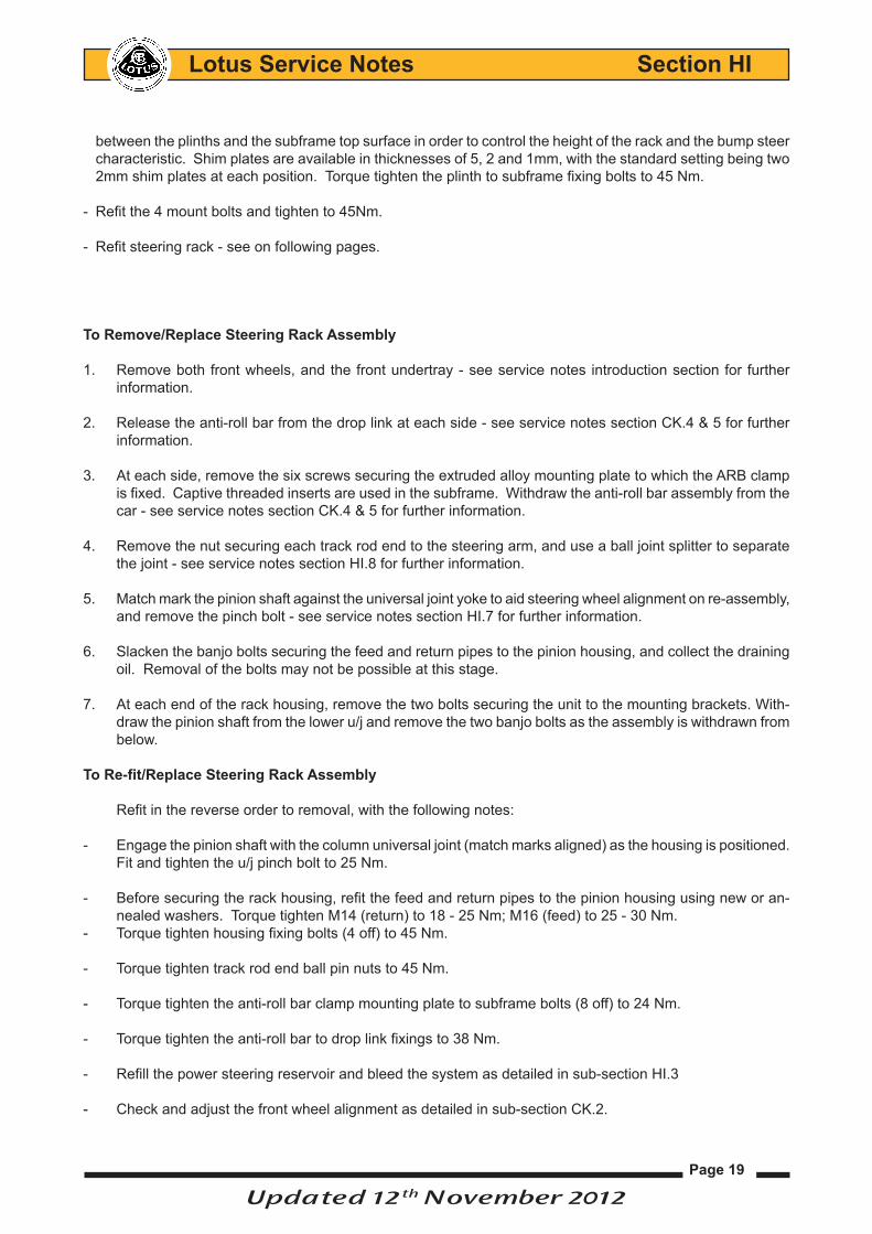
between the plinths and the subframe top surface in order to control the height of the rack and the bump steer characteristic. Shim plates are available in thicknesses of 5, 2 and 1mm, with the standard setting being two 2mm shim plates at each position. Torque tighten the plinth to subframe fixing bolts to 45 Nm.
Refit the 4 mount bolts and tighten to 45Nm. -
Refit steering rack - see on following pages. -
To Remove/Replace Steering Rack Assembly
1. Remove both front wheels, and the front undertray - see service notes introduction section for further information.
2. Release the anti-roll bar from the drop link at each side - see service notes section CK.4 & 5 for further information.
3. At each side, remove the six screws securing the extruded alloy mounting plate to which the ARB clamp is fixed. Captive threaded inserts are used in the subframe. Withdraw the anti-roll bar assembly from the car - see service notes section CK.4 & 5 for further information.
4. Remove the nut securing each track rod end to the steering arm, and use a ball joint splitter to separate the joint - see service notes section HI.8 for further information.
5. Match mark the pinion shaft against the universal joint yoke to aid steering wheel alignment on re-assembly, and remove the pinch bolt - see service notes section HI.7 for further information.
6. Slacken the banjo bolts securing the feed and return pipes to the pinion housing, and collect the draining oil. Removal of the bolts may not be possible at this stage.
7. At each end of the rack housing, remove the two bolts securing the unit to the mounting brackets. With-draw the pinion shaft from the lower u/j and remove the two banjo bolts as the assembly is withdrawn from below.
To Re-fit/Replace Steering Rack Assembly
Refit in the reverse order to removal, with the following notes:
- Engage the pinion shaft with the column universal joint (match marks aligned) as the housing is positioned. Fit and tighten the u/j pinch bolt to 25 Nm.
- Before securing the rack housing, refit the feed and return pipes to the pinion housing using new or an-nealed washers. Torque tighten M14 (return) to 18 - 25 Nm; M16 (feed) to 25 - 30 Nm.
- Torque tighten housing fixing bolts (4 off) to 45 Nm.
- Torque tighten track rod end ball pin nuts to 45 Nm.
- Torque tighten the anti-roll bar clamp mounting plate to subframe bolts (8 off) to 24 Nm.
- Torque tighten the anti-roll bar to drop link fixings to 38 Nm.
- Refill the power steering reservoir and bleed the system as detailed in sub-section HI.3
- Check and adjust the front wheel alignment as detailed in sub-section CK.2.
Updated 12th November 2012

Page 20
Lotus Service Notes Section HI
HI.10 - PAS PUMP & TESTING PROCEDURE
The vane type, constant displacement hydraulic pump is mounted on the right hand front of the cylinder block, and is driven by the automatically tensioned multi-rib auxiliary belt from the crankshaft pulley. To check for correct functionality, the steering effort may be checked with the engine running and the car stationary:
PAS Pump Test Procedure
Tools requiredPAS Pressure Test Gauge Kit - use a universal kit, or Toyota part number 09640-10010
1. Remove the rear clamshell (see Sub-Section BV.6).
2. Check auxiliary drive belt condition and fluid level. With engine idling, turn the steering from lock to lock several times to raise fluid temperature and check for foaming or emulsification; if necessary, bleed the system (see Sub-Section HI.3).
3. Remove the banjo bolt connecting the pressure outlet pipe to the PAS pump. Fit the adaptor pipe from the test kit into the pump, and connect the gauge inlet pipe to the adaptor.
4. Connect the outlet pipe on the gauge to the banjo connector using the union adaptor.
5. Open the gauge valve, and bleed the system of air (see above).
6. With the engine idling, turn the steering from lock to lock several times to raise fluid temperature (70 - 80°C).
7. With the engine idling, close the gauge valve and observe the gauge reading - Do not keep the valve closed for more than 10 seconds, or excessive oil heating will occur.
Minimum fluid pressure: 7800 to 8300 kPa (1100 to 1200 psi).
8. With the engine idling, open the gauge valve fully and measure the pressure at engine speeds of 1000 and 3000 rpm.
Maximum difference: 490 kPa (70 psi).
9. With the engine idling and the gauge valve fully open, turn the steering to full lock and measure the fluid pressure. Repeat for the opposite lock - Do not keep on full lock for more than 10 seconds, or exces-sive oil heating will occur.
Minimum fluid pressure: 7800 to 8300 kPa (1100 to 1200 psi).
10. Disconnect the gauge pipes and refit the banjo union to the pump. Bleed the system of air, see sub-section HI.3.
Updated 12th July 2012

Page 21
Lotus Service Notes Section HI
HI.11 - PAS PUMP REMOVAL & INSPECTION
The vane type, constant displacement hydraulic pump is mounted on the right hand front of the cylinder block, and is driven by the automatically tensioned multi-rib auxiliary belt from the crankshaft pulley. The pump is secured to the engine by two bolts,
Removal:1. Remove the rear undertray (see service notes introduction section).
2. Use a syringe to empty the PAS reservoir of oil and reduce potential spillage (see sub-section HI.3).
3. Relieve the tension on the auxillary belt - see service notes sub section EJ.4 for information. Mark the direction of rotation on the belt before unhooking from the PAS pump pulley.
4. Disconnect the reservoir hose from the pump, and plug both the hose and pump port.
5. Release the banjo union bolt from the high pressure feed pipe bolted to the pump (torque 30Nm), collect both banjo gaskets and plug both the pipe and pump port.
6. Disconnect the harness from the PAS pump pressure switch (only fitted to early start of production vehi-cles).
7. The pump is secured to the engine by two bolts, accessible between the spokes of the pulley. Remove
Ratchet
PASpumppulley
RHdriveshaft
PASreservoirhose
PASsteering rackfeed hose
h77
Auxillarydrivebelt
Upper mounting bolt
Lower mounting bolt
Vane pump assembly
Union banjo bolt
Pressure pipe tosteering rack
Fluid pressure switch har-nessconnector(iffitted)
PAS reservoirto pump hose
h72
Updated 12th July 2012

Page 22
Lotus Service Notes Section HI
the upper and lower bolts (both torqued to 43Nm).
8. Withdraw the pump from underneath the vehicle. Refitment:Reversal of removal except:- Access to the pump bolts from under the vehicle using a torque wrench may be limited. Better access may
be achieved by removing the RHR wheelarch liner - see section BV.17, then torque tightening the upper PAS pump using a suitable socket and extension from above the subframe as illustrated. The lower bolt may be accessed via the subframes driveshaft aperture.
- Fit the banjo bolt with two new washers and connect the high pressure pipe to the pumps outlet union,
(torque to 30Nm). Care point: Removing the PAS pump from the engine block may cause the union bolt securing the high pressure fluid pipe to the pump body to loosen which may potentially cause a power steering fluid leak.
Once the PAS pump is refitted to the engine, it is essential to check the torque of the high pressure pipe union bolt (torque 30Nm).
To gain access to the union bolt to check the torque will require the removal of the engine access panel in the luggage compartment; see service notes section EJ.2 for further information.
- Refit the auxiliary drive belt to all pulleys, ensuring that the belt ribs are correlty located on each drive pulley. Rotate the tensioner counterclockwise to relieve tension, and remove the tensioner locking pin.
- Refill and bleed the PAS system, see sub-section HI.3 and check for leaks.
h78
Upper PAS bolt access through RHR wheelarch above subframe
Torque wrench
Updated 12th November 2012

Page 23
Lotus Service Notes Section HI
HI. 12 - POWER STEERING RESERVOIR REMOVAL/REPLACEMENT
Removal:Remove the RHR wheelarch liner – see service notes section BV.17.
Use a syringe to empty the PAS reservoir of oil and 1. reduce potential spillage (see sub-section HI.3).
Release the upper hose clip securing the subframe 2. heat duct pipe to the clamshell exit vent, pull the top section of the pipe to one side to gain access to the rearmost PAS reservoir bracket to back stay fixing bolt.
Release and remove the 3 M8 bolts and nuts (torque 3. 10NM) securing the PAS bracket to the backstay, taking care not to place any strain on the PAS hoses, position the PAS reservoir downwards.
Release the clips securing the steering rack return 4. hose and PAS pump hose to the reservoir and allow any excess fluid to drain into a suitable container.
Any residual fluid remaining in the reservoir assem-5. bly can now be drained into a suitable container.
Refitment:Reversal of removal except:
Refill reservoir with suitable PAS fluid and bleed system as necessary – see sub section HI.3 for further infor-mation.
h75
h76
2. Subframe heat duct pipe
1. PAS reservoir
3. PAS reservoirfixings
4. PAS reservoir hose clips
Updated 16th October 2012