Lorenzo DAGHINI Andreas ARCHENTI Tomas OSTERLIND … · 38 Lorenzo DAGHINI, Andreas ARCHENTI, Tomas...
12
Journal of Machine Engineering, Vol. 13, No. 1, 2013 high damping interface, cutting stability, operational dynamic properties, machine tool design Lorenzo DAGHINI 1 Andreas ARCHENTI 1 Tomas OSTERLIND 1 EXTENDING STABILITY LIMITS BY DESIGNED-IN DAMPING With advances in material technology come challenges to productivity. New materials are, in fact, more difficult to machine with regards to tool wear and especially machine tool stability. This paper proposes to extend the stability limits of the machining system by enhancing the structure’s damping capability. The aim of the research work presented here is to introduce a unified concept based on the distribution of damping within the machining system components exploiting the dynamic properties of the existing joints. To maintain a high level of static stiffness, it was chosen to adapt hydrostatic clamping systems to the tools. Damping is designed in the structure via high damping interfaces (HDI), intentionally introduced interfaces where the damping ratio is enhanced by introduction of viscoelastic polymer metal composites between the two metallic surfaces composing the interface. In this paper HDI are introduced at two joints, between tool and turret and between turret and lathe. The tests show that the designed-in damping is effective and allows extending the stability limits of the machining system. The implementation of designed-in damping allows the end user to select the most suitable parameters in terms of productivity avoiding the hassle of tuning the devices, having to acquire a deep knowledge in structural dynamics or having to use additional control systems. In addition to this, the enhanced machine tool system becomes less sensitive to stability issues provoked by difficult-to-machine materials or even fluctuations of the work material properties that might occur in everyday production processes. 1. INTRODUCTION With the advances in material technology, allowing, for instance, engines to withstand higher combustion pressure and consequently improved performance, come challenges to productivity. These materials are, in fact, more difficult to machine with regards to tool wear and especially machine tool stability [1]. To cope with this, the usual strategy has been to lower the cutting parameters to a safe level with regards to stability. The research work presented here addresses this problem and proposes what is thought to be the most viable solution. The issue of machining vibration has been addressed by many [2], however, most research effort in the subject has been concentrating on the refinement of the stability limits computation based on the theories originally introduced by Tobias [3] and Tlusty [4]. Yet __________________ 1 KTH Royal Institute of Technology, Machine and Process Technology, Stockholm, Sweden
Transcript of Lorenzo DAGHINI Andreas ARCHENTI Tomas OSTERLIND … · 38 Lorenzo DAGHINI, Andreas ARCHENTI, Tomas...

Journal of Machine Engineering, Vol. 13, No. 1, 2013
high damping interface, cutting stability, operational dynamic properties,
machine tool design
Lorenzo DAGHINI1 Andreas ARCHENTI1 Tomas OSTERLIND1
EXTENDING STABILITY LIMITS BY DESIGNED-IN DAMPING
With advances in material technology come challenges to productivity. New materials are, in fact, more difficult to machine with regards to tool wear and especially machine tool stability. This paper proposes to extend the stability limits of the machining system by enhancing the structure’s damping capability. The aim of the research work presented here is to introduce a unified concept based on the distribution of damping within the machining system components exploiting the dynamic properties of the existing joints. To maintain a high level of static stiffness, it was chosen to adapt hydrostatic clamping systems to the tools. Damping is designed in the structure via high damping interfaces (HDI), intentionally introduced interfaces where the damping ratio is enhanced by introduction of viscoelastic polymer metal composites between the two metallic surfaces composing the interface. In this paper HDI are introduced at two joints, between tool and turret and between turret and lathe. The tests show that the designed-in damping is effective and allows extending the stability limits of the machining system. The implementation of designed-in damping allows the end user to select the most suitable parameters in terms of productivity avoiding the hassle of tuning the devices, having to acquire a deep knowledge in structural dynamics or having to use additional control systems. In addition to this, the enhanced machine tool system becomes less sensitive to stability issues provoked by difficult-to-machine materials or even fluctuations of the work material properties that might occur in everyday production processes.
1. INTRODUCTION
With the advances in material technology, allowing, for instance, engines to withstand higher combustion pressure and consequently improved performance, come challenges to productivity. These materials are, in fact, more difficult to machine with regards to tool wear and especially machine tool stability [1]. To cope with this, the usual strategy has been to lower the cutting parameters to a safe level with regards to stability. The research work presented here addresses this problem and proposes what is thought to be the most viable solution. The issue of machining vibration has been addressed by many [2], however, most research effort in the subject has been concentrating on the refinement of the stability limits computation based on the theories originally introduced by Tobias [3] and Tlusty [4]. Yet
__________________ 1 KTH Royal Institute of Technology, Machine and Process Technology, Stockholm, Sweden

38 Lorenzo DAGHINI, Andreas ARCHENTI, Tomas OSTERLIND
this approach is not widespread within industry due to the limitations still left for researchers to deal with.
To begin with, this approach lacks of an absolute stability criterion [5], in addition to this stability limit diagrams (SLD) are sensitive to the accuracy of the structural analysis [6]; therefore, in order to attain accurate and reliable results, the analysis ought to be carried out by personnel with experience in the field. Further, once the SLD is computed, it only applies to the specific configuration of workpiece (material and geometry) and tool. In addition to this, this approach cannot take into account non-linear behaviours and for structural dynamics variations of the parts and machines along the tool path [7],[8], this being the most common occurrence in the manufacturing of advanced products. Last but not least, in the cases when the SLD might be accurately and reliably employed, the usual strategy is to select a higher cutting speed in order to be able to machine in stable conditions with a higher depth of cut. On the other hand, this might compromise tool life, as this is strongly dependent on temperature, which in turns increases with cutting speed, thus affecting productivity as the machining process needs to be interrupted more often for tool change and consequently production costs might increase.
Therefore, this paper proposes to extend the stability limits of the machine system by enhancing the structure’s damping capability. This would allow for maintaining or even improving productivity since the range of stable cutting parameters might be stretched to such an extent that the user is enabled to freely choose the cutting speed for the operation without having to be concerned about stability. Most effort in improving machining performance by changing the machining system structural behaviour (either by active or passive means) has been concentrating solely on one specific component at the time [2]. The aim of the research work presented here is therefore to introduce a unified concept based on the distribution of damping within the machining system components exploiting the dynamic properties of the existing joints composing the machine tool structure as machine tools are generally over dimensioned in terms of strength [5] and most of the damping capability is generated by the very joints comprising the structure [9],[10].
2. DESIGNED-IN DAMPING
The ultimate objective when designing machine tool components capable of withstanding cutting instability in a passive manner is to enhance both stiffness and damping. On the other hand, these two properties are intrinsically linked to one another and the enhancement of one, usually compromises the other [11]. It is in fact well known that for the majority of machining operations it is the product of stiffness (K) and damping (δ) that determines the vibratory conditions in the system [11].
Another aspect to take in consideration is that the overall damping ability of a complex structure, such as a machine tool, not only depends on the individual components’ damping capacity but also, and more considerably, on the damping associated with joints between the very components [9],[10]. Thus the necessity to make use of different components of the machine tool for enhancing both K and δ.

Extending Stability Limits by Designed-in Damping 39
2.1. MAXIMIZING STIFFNESS USING HYDROSTATIC CLAMPING
To maintain a high level of static stiffness, it was chosen to adapt hydrostatic clamping systems to the tools. The effect of this kind of clamping system on the tool deflection is well recognized [12] and straightforward to compute. If the tool is considered to be a cantilever beam, with infinite clamping stiffness, then its transversal vibration will be derived from the equation:
2
2
2
2
2
2 ),(),(
t
txvA
x
txvEI
x ∂∂−=
∂∂
∂∂ ρ
(1)
where E is the Young modulus, I is the moment of inertia, ρ is the density A is the area of the beam section and v(x,t) is the displacement of the beam as a function of position (x) and time (t). The well-known solution for computing the deflection of a cantilever beam under static load is given by equation (2):
IE
LF
⋅⋅⋅=
3
3
δ
(2)
where L represents the overhang. When expressing the moment of inertia for a round section beam (as the common
boring bars have) equation (2) becomes:
3
4
3
3
64
3
64
⋅⋅⋅⋅
⋅=⋅⋅⋅⋅⋅=
d
L
dE
F
dE
LF
ππδ
(3)
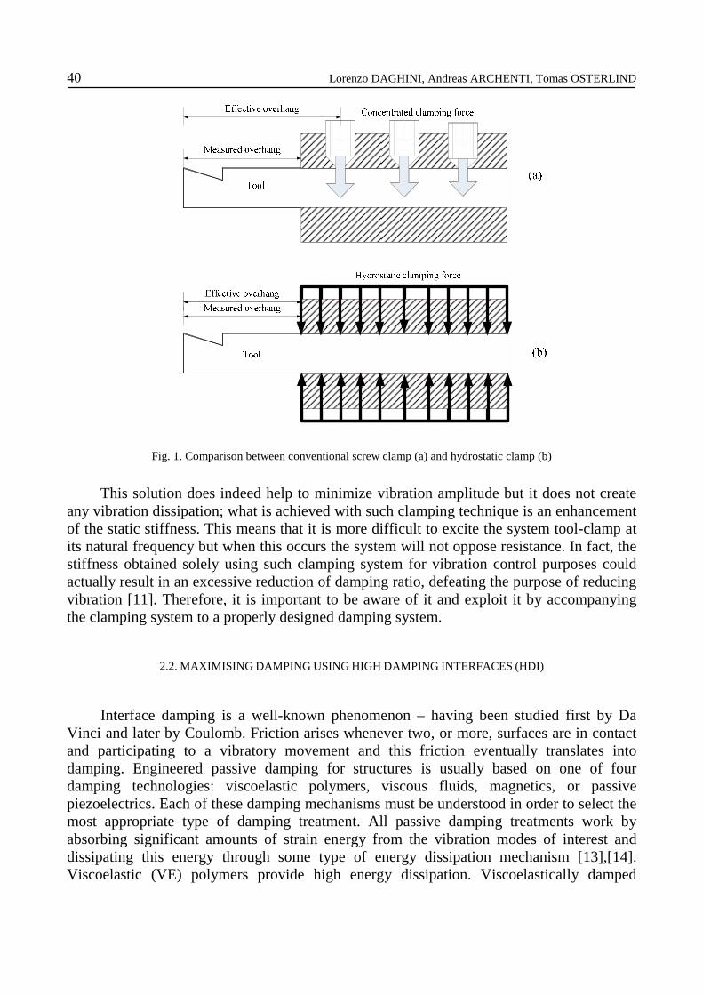
where d is the beam section diameter. Equation (3) puts in evidence the importance of the ratio between the overhang and the
section diameter. It is common knowledge that the effective overhang of a tool has to be considered from the outmost fixed point [12], which is the first screw on the conventional screw clamp, and the outmost face on the hydrostatic clamp (see Fig. 1). Thus the measured overhang of a tool mounted in a screw clamp does not correspond to the effective overhang. The effect of the hydrostatic clamp can be easily quantified by employing equation (3) to compute the deflection of the tool clamped in it (δH) and in the screw clamp (δC). As the screw is usually positioned 12mm from the end of the clamp, the effective overhang of the tool mounted in the screw clamp will be 12 mm longer than the one of the tool clamped in the hydrostatic clamp. The relative difference can be expressed by (4):
C
HCrel δ
δδδ −=
(4)
If, for instance, a boring bar is mounted with a measured overhang of 120mm, its deflection can be reduced by 25% by employing a hydrostatic clamp instead of a conventional screw clamp.
40 Lorenzo DAGHINI, Andreas ARCHENTI, Tomas OSTERLIND
Fig. 1. Comparison between conventional screw clamp (a) and hydrostatic clamp (b)
This solution does indeed help to minimize vibration amplitude but it does not create any vibration dissipation; what is achieved with such clamping technique is an enhancement of the static stiffness. This means that it is more difficult to excite the system tool-clamp at its natural frequency but when this occurs the system will not oppose resistance. In fact, the stiffness obtained solely using such clamping system for vibration control purposes could actually result in an excessive reduction of damping ratio, defeating the purpose of reducing vibration [11]. Therefore, it is important to be aware of it and exploit it by accompanying the clamping system to a properly designed damping system.
2.2. MAXIMISING DAMPING USING HIGH DAMPING INTERFACES (HDI)
Interface damping is a well-known phenomenon – having been studied first by Da Vinci and later by Coulomb. Friction arises whenever two, or more, surfaces are in contact and participating to a vibratory movement and this friction eventually translates into damping. Engineered passive damping for structures is usually based on one of four damping technologies: viscoelastic polymers, viscous fluids, magnetics, or passive piezoelectrics. Each of these damping mechanisms must be understood in order to select the most appropriate type of damping treatment. All passive damping treatments work by absorbing significant amounts of strain energy from the vibration modes of interest and dissipating this energy through some type of energy dissipation mechanism [13],[14]. Viscoelastic (VE) polymers provide high energy dissipation. Viscoelastically damped
Extending Stability Limits by Designed-in Damping 41
structures have been successfully applied in many engineering fields, particularly in the aerospace industry [15].
High damping interfaces (HDI) are intentionally introduced interfaces where the damping ratio is enhanced by introduction of VE polymer metal composites between the two metallic surfaces composing the interface. As every vibratory mode is characterized by its own damping ratio (and natural frequency), the HDI is effective in those modes where the mode shape involves the HDI, i.e. when the VE polymer composite experiences shear strain [16]. Therefore the positioning of such interface is of vital importance.
2.3. UNIFIED CONCEPT OF DISTRIBUTED DESIGNED-IN DAMPING
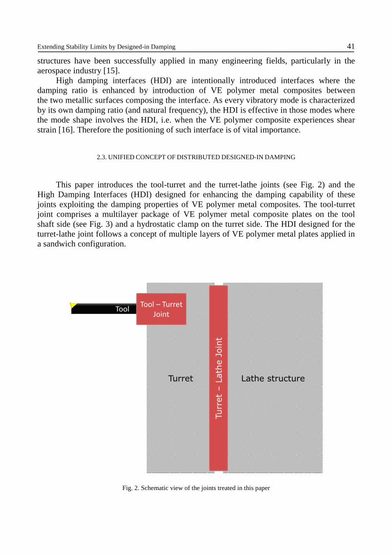
This paper introduces the tool-turret and the turret-lathe joints (see Fig. 2) and the High Damping Interfaces (HDI) designed for enhancing the damping capability of these joints exploiting the damping properties of VE polymer metal composites. The tool-turret joint comprises a multilayer package of VE polymer metal composite plates on the tool shaft side (see Fig. 3) and a hydrostatic clamp on the turret side. The HDI designed for the turret-lathe joint follows a concept of multiple layers of VE polymer metal plates applied in a sandwich configuration.
Lathe structure
Tool
Turret
Tool – Turret
Joint
Turret –Lathe Joint
Fig. 2. Schematic view of the joints treated in this paper

42 Lorenzo DAGHINI, Andreas ARCHENTI, Tomas OSTERLIND
Fig. 3. Multiple layers of VE polymer metal composite plates implemented in a parting-off tool and in a boring bar
3. PERFORMANCE EVALUATION
Traditional evaluation of machining system dynamic behaviour has invariably been approached in the following steps:
1. Identification of the dynamic properties of elastic structure of machine tools. 2. Identification of the characteristics of cutting process, i.e. the dynamic parameters
describing the transfer function of the subsystem represented by cutting process. 3. Evaluation of dynamic stability of the machining system from step 1 and step 2.
The first step is experimentally carried out through experimental modal analysis (EMA) and the second by machining tests, where the acoustic signal or the vibration acceleration is recorded. In some cases these signals are analysed using model based identification algorithms [18] in order to extract the operational dynamic parameters (ODP) [5],[18],[19]. The results of the EMA have been also employed to extract the stability limit diagram used to compare a conventional tooling system with the proposed design.
3.1. OPERATIONAL DYNAMIC PARAMETERS – MODEL-BASED IDENTIFICATION
In machining, majority of on-line systems for detecting self-excited vibrations are based on non-parametric method which uses a quantitative criterion (e.g. vibration amplitude) to discriminate forced and self-excited vibrations. However, the quantitative criterion is not consistent with the nature of vibrations. A high amplitude vibration can be the result of a stable system working close to resonance or in condition of tougher cutting parameters [5],[18],[19].The concept of ODP is introduced because the machining system is a closed-loop system. The structural damping of the machine tool elastic structure and the dynamic cutting process damping cannot, from a response measure point of view, be separated. Through ODP the contribution of the structural vibration modes and process vibration modes resulting during machining system operation is denoted. The ODP consists

Extending Stability Limits by Designed-in Damping 43
of operational damping ratio (ODR) and operational frequency (OF). The ODR, ξop, is the overall damping of the machining system and consists of modal damping, ξmod and process
damping, ξcp. The interference between relief face and work piece results in a rubbing force acting against the direction of the cutting force that leads to a positive damping effect. This is known as process damping.
By using parametric identification models, i.e. model-based identification, in the recursive implementation, qualitative criteria can be implemented. Such a criterion is ODR. A non-conservative mechanical system with positive ODR is said to be dynamically stable, whereas one with negative ODR is said to be unstable.
(1)
(3)
(4)
(2)
(1) (2) (3) (4)
Co
mp
lia
nce
[m/N
]
(x1
0-6
)
Frequency [Hz]
Fig. 4. Result of EMA on boring bar: compliance: (1) Damped boring bar in VDI adapter with traditional screw clamp, (2) Damped tool in a hydrostatic clamp, (3) Conventional tool in VDI adapter with traditional screw clamp,
(4) Conventional tool in a hydrostatic clamp
3.2. RESULTS
The EMA characterising the tool-turret joint (see Fig. 2) gave the result illustrated in Fig. 4, where a comparison of the compliance of the damped and conventional boring bar

44 Lorenzo DAGHINI, Andreas ARCHENTI, Tomas OSTERLIND
mounted in a conventional screw clamp and in a hydrostatic clamp is presented. The damped boring bar displays lower compliance than the conventional one when both are mounted in the conventional screw clamp (curve 1 vs. curve 3 in Fig. 4). However, the highest dynamic stiffness is displayed by the damped boring bar mounted in the hydrostatic clamp (curve 2 in Fig. 4). Based on this result a comparative SLD for the damped boring bar mounted in the hydrostatic clamp and the conventional boring bar mounted in the screw clamp has been computed assuming that the tools would machine exactly the same workpiece having a hypothetical cutting force coefficient of 1500N/mm2 (see Fig. 5). This comparison already gives an indication of the achievable higher stability limit for the combination of damped tool and hydrostatic clamp. As Fig. 5 illustrates, the asymptotical depth of cut limit is almost three times larger for the damped boring bar.
600 700 800 900 1000 1100 1200 1300 1400 15000
0.5
1
1.5
2
Spindle speed [rev/min]
a p [mm
]
Asymptotical depth of cut limit
De
pth
of
cut,
Fig. 5. Stability limit diagrams (SLD) for the boring bar mounted in the screw clamp (red) and the damped boring bar mounted in the hydrostatic clamp (blue),
(The damped boring bar is capable of cutting at higher depth of cut in perfectly stable conditions)
More accurate information on the effectiveness of these improvements can be extracted only after machining tests. Preliminary tests were carried out in form of internal turning on 34CrNiMoS6 (SS 2541) bars with an outer diameter of 150mm, inner diameter of 48mm and a length of 170mm. The tests were performed in a SMT Swedturn 300 at three different depths of cut (ap), 1mm, 2mm and 3mm, keeping a constant cutting speed (vc) at 120m/min and feed (f) at 0,15mm/rev. The boring bars had a section diameter d=25mm and the overhang was set to be L=125mm (i.e. L/d=5). Both conventional and damped boring bars were mounted in the hydrostatic clamp. The acoustic signals have been analysed through model based identification in order to quantify the ODPs (operational frequency, OF, and operational damping ratio, ODR). Fig. 6 shows the damping ratio variations as the tool enters the workpiece (at the left end of the figure) and exits close to the chuck (at the right end of the picture). The operational damping ratio for the conventional

Extending Stability Limits by Designed-in Damping 45
boring bar goes towards zero during the machining of the whole length of the workpiece. The damped boring bar worked in stable conditions throughout the whole length of the workpiece with a tendency of stability increase as the tool approaches the chuck.
0,0001
0,001
0,01
0,1
1
1 2 3 4 5 6 7 8 9 10
Da
mp
ing
Ra
tio
ξξ ξξ
Sample window
Damped tool ap=1mm Conventional tool ap=1mmDamped tool ap=1mm Conventional tool ap=1mm
Fig. 6. Operational damping ratio identified with ARMA(3,2) model
In order to evaluate the effectiveness of an enhancement of damping on both the treated joints (Fig. 2) further testing was carried out. The operation was internal turning of SS2541 steel. Surface roughness (Ra) has been used as criterion. The chosen cutting parameters are summarized in Table 1.
Table 1 Cutting data settings
# n [rpm]
ap [mm]
f [mm/rev]
1 1040 1 0,15 2 1040 2 0,15 3 1040 3 0,15 4 800 1 0,15 5 800 2 0,15 6 800 3 0,15 7 560 1 0,15 8 560 2 0,15 9 560 3 0,15

46 Lorenzo DAGHINI, Andreas ARCHENTI, Tomas OSTERLIND
0,60
0,90
1,20
1,50
1,80
2,10
2,40
2,70
3,00
1 2 3 4 5 6 7 8 9
Ra
[ µµ µµm
]
Cutting data settings
HDI Tool+HDI Turret
HDI Tool + Convl Turret
Convl. Tool + HDI Turret
Convl. Tool + Convl. turret
Fig. 7. Machining test results, surface roughness. Comparison between the conventional tool clamped in conventional turret and in the damped turret (HDI Turret), as well as the damped tool (HDI tool) clamped in the conventional
turret and in the damped one. The conventional tool clamped in the conventional turret could not perform at setting 7, 8 and 9 due to excessive instability
From Fig. 7 it appears evident that the ordinary configuration (conventional boring bar and conventional turret) suffers from grave instability when machining at settings 7, 8 and 9 (see Table 1 for details). A considerable improvement is attained when either of the joints is improved through a HDI. The introduction of damping makes possible to machine even at those cutting data settings that generated instability. In addition to this the overall surface roughness is somewhat improved even for those cutting parameters where signs of instability are not as manifest. Further improvement of the resulting surface quality is attained when the HDI is implemented on both the joints.
4. DISCUSSION AND CONCLUSIONS
The machining tests here illustrated demonstrate that a significant improvement of machining performance can be attained by solely employing the HDI in the tool-turret joint. The comparison of The ODR computed on the acoustic signals recorded during machining generated by the conventional and damped boring bar clamped in a conventional turret demonstrates that the sole improved tool-turret joint is capable of machining in stable

Extending Stability Limits by Designed-in Damping 47
conditions whereas the conventional configuration of tool and turret shows signs of instability already at the lowest tested depth of cut. The measured surface roughness quantifies the improvement allowed by the sole HDI between tool and turret to a 50% reduction. In conclusion it is the employment of the full chain of redesigned components (tool-clamp-turret) that enables to generate the lowest surface roughness over the whole range of tested cutting parameters. In addition to this, the improved machining system is not affected by instability at any of the tested cutting parameters.
From the industrial application point of view, the implementation of designed-in damping allows the end user to select the most suitable parameters in terms of productivity avoiding the hassle of tuning the devices, having to acquire a deep knowledge in structural dynamics or having to use additional control systems. In addition to this, the enhanced machine tool system becomes less sensitive to stability issues provoked by difficult-to-machine materials or even fluctuations of the work material properties that might occur in everyday production processes.
ACKNOWLEDGMENTS
The authors would like to express their gratitude to KTH/DMMS (Centre for design and management of manufacturing systems), Scania CV AB, Mircona AB and Spirex tools for supporting this research. This paper is the result of the FFI Robust Machining, financed through VINNOVA, the Swedish Governmental Agency for Innovation Systems.
REFERENCES
[1] BERGLUND A., 2011, Criteria for machinability evaluation of compacted graphite iron materials, Stockholm, Sweden, KTH - Production Engineering, PhD Thesis.
[2] QUINTANA G., CIURANA J., 2011, Chatter in machining processes: A review, International Journal of Machine Tools and Manufacture, May, 51/5, 363-376.
[3] TOBIAS S.A., 1965, Machine tool vibration, Glasgow, Blackie & Son. [4] TLUSTY J., ZATON W., ISMAIL F., 1983, stability lobes in milling, CIRP Annals - Manufacturing Technology,
32/1, 309-313. [5] ARCHENTI A., 2011, A Computational framework for control of machining system capability, Stockholm,
Sweden, KTH - Production Engineering, PhD Thesis. [6] RASPER P., ROTT O., HÖMBERG D., UHLMANN E., 2010, Analysis of uncertainties in the stability prediction
for milling processes, CIRP 2nd International Conference on Process Machine Interactions, Vancouver, BC, Canada.
[7] ALTINTAS Y., WECK M., 2004, Chatter stability of metal cutting and grinding, CIRP Annals - Manufacturing Technology, 53/2, 619-642.
[8] SELLMEIER V., DENKENA B., 2010, Stable islands in the stability chart of milling processes due to unequal tooth pitch, International Journal of Machine Tools and Manufacture, February, 51/2, 152-164.
[9] STEPHENSON D.A., AGAPIOU J.S., 2006, Metal cutting theory and practice, Boca Raton, FL, USA, CRC Press.
[10] RIVIN E. I., 1999, Stiffness and damping in mechanical design, New York, NY, USA, Marcel Dekker. [11] RIVIN E.I., et al., 2000, Tooling structure: interface between cutting edge and machine tool, CIRP Annals -
Manufacturing Technology, 2nd ed., 49, 591-634. [12] DAGHINI L., 2008, Theoretical and experimental study of tooling systems, Stockholm, Sweden, Royal Institute of
Technology, KTH Production Engineering, Licenciate Thesis. [13] JOHNSON C.D., 1981, Passive damping technology using viscoelastics, 30th Conference on Decision and
Control, Brighton, England.

48 Lorenzo DAGHINI, Andreas ARCHENTI, Tomas OSTERLIND
[14] GIBSON W.C., AUSTIN E.M., 1993, Analysis and design of damped structures, Finite Elements in Analysis and Design, 14, 337-351.
[15] ROGERS L., 1978, Polymeric viscoelastic damping technology for the 80's, Proceeding on the conference on aerospace.
[16] ROSS D., UNGAR E.E., KERWIN E.M., 1959, Damping of plate flexural vibrations by means of viscoelastic laminae, ASME, Structural Damping, 49–88.
[17] ARCHENTI A., NICOLESCU C.M., 2008, Model-based identification of dynamic stability of machining system, 1st International Conference on Process Machine Interaction - Proceedings, Hannover, Germany, 41-52.
[18] ARCHENTI A., NICOLESCU C.M, 2010, Recursive estimation of operational dynamic parameters in milling using acoustic signal, 2nd International Conference on Process Machine Interactions, Vancouver, BC, Canada.
[19] ARCHENTI A., NICOLESCU C.M., 2009, Model-based identification of manufacturing processes operational dynamic parameters, International Conference on New Technologies in manufacturing NewTech, Galati, Romania.