Loads - Types - PDH Source, LLC · • Typical unit weight of structural materials ... Loads,...
48
Loads Moayyad Al Nasra, PhD, PE 1 (c) Al Nasra
Transcript of Loads - Types - PDH Source, LLC · • Typical unit weight of structural materials ... Loads,...
Loads
Moayyad Al Nasra, PhD, PE
1 (c) Al Nasra
Loads - Types
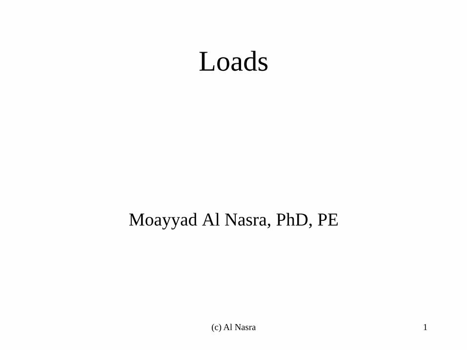
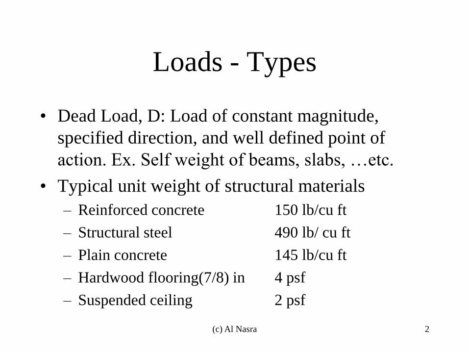
• Dead Load, D: Load of constant magnitude,
specified direction, and well defined point of
action. Ex. Self weight of beams, slabs, …etc.
• Typical unit weight of structural materials
– Reinforced concrete 150 lb/cu ft
– Structural steel 490 lb/ cu ft
– Plain concrete 145 lb/cu ft
– Hardwood flooring(7/8) in 4 psf
– Suspended ceiling 2 psf
2 (c) Al Nasra
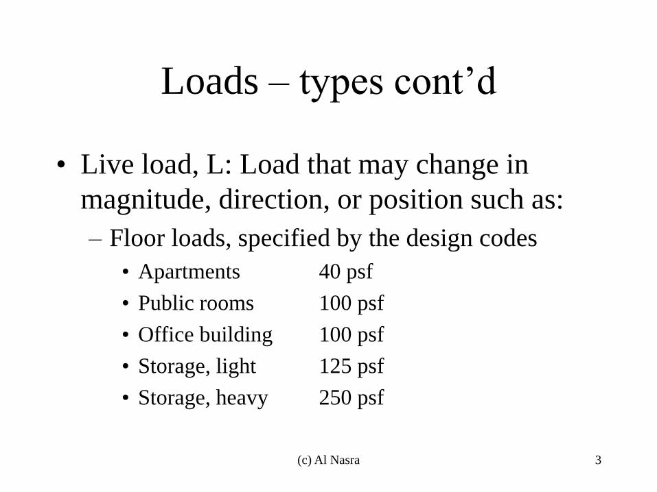
Loads – types cont’d
• Live load, L: Load that may change in
magnitude, direction, or position such as:
– Floor loads, specified by the design codes
• Apartments 40 psf
• Public rooms 100 psf
• Office building 100 psf
• Storage, light 125 psf
• Storage, heavy 250 psf
3 (c) Al Nasra
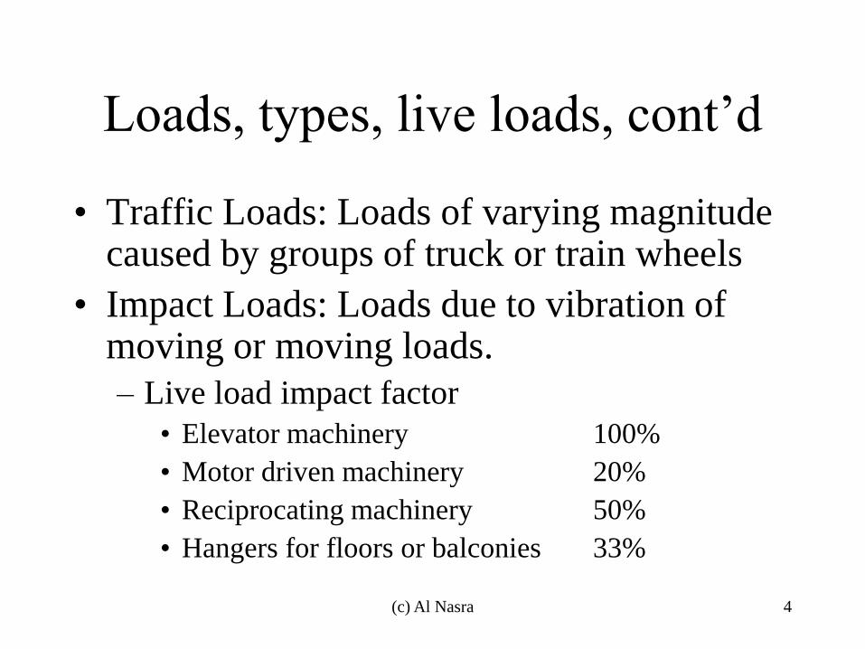
Loads, types, live loads, cont’d
• Traffic Loads: Loads of varying magnitude caused by groups of truck or train wheels
• Impact Loads: Loads due to vibration of moving or moving loads.
– Live load impact factor
• Elevator machinery 100%
• Motor driven machinery 20%
• Reciprocating machinery 50%
• Hangers for floors or balconies 33%
4 (c) Al Nasra
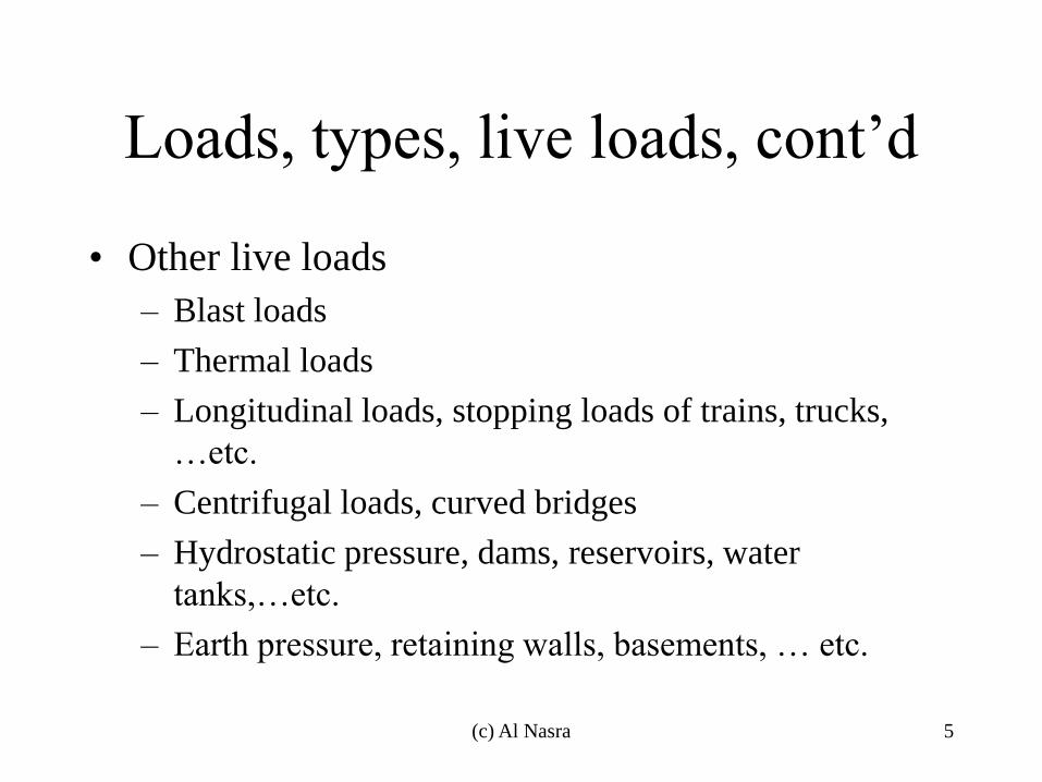
Loads, types, live loads, cont’d
• Other live loads
– Blast loads
– Thermal loads
– Longitudinal loads, stopping loads of trains, trucks,
…etc.
– Centrifugal loads, curved bridges
– Hydrostatic pressure, dams, reservoirs, water
tanks,…etc.
– Earth pressure, retaining walls, basements, … etc.
5 (c) Al Nasra

Loads, types, cont’d
• Environmental loads
– Snow loads: 1 inch of snow is equivalent of 5 psf. Common values ranges between 10 psf to 40 psf.
– Rain loads: The best method of preventing ponding is to have an appreciable slope of the roof at least ¼ in per foot.
– Wind load, Hurricanes and tornados, … etc.
– Earthquake loads, seismic forces
6 (c) Al Nasra

LRFD load combinations
• U= 1.4 D
• U= 1.2 D + 1.6 L + 0.5 (Lr or s or R)
• U= 1.2 D + 1.6 (Lr or s or R) + (0.5L or 0.8W)
• U= 1.2 D + 1.6 W + 0.5 L +0.5( Lr or s or R)
• U= 1.2 D +/- 1.0 E + 0.5 L + 0.2 S
• U= 0.9 D +/- (1.6 W or 1.0 E)
7 (c) Al Nasra
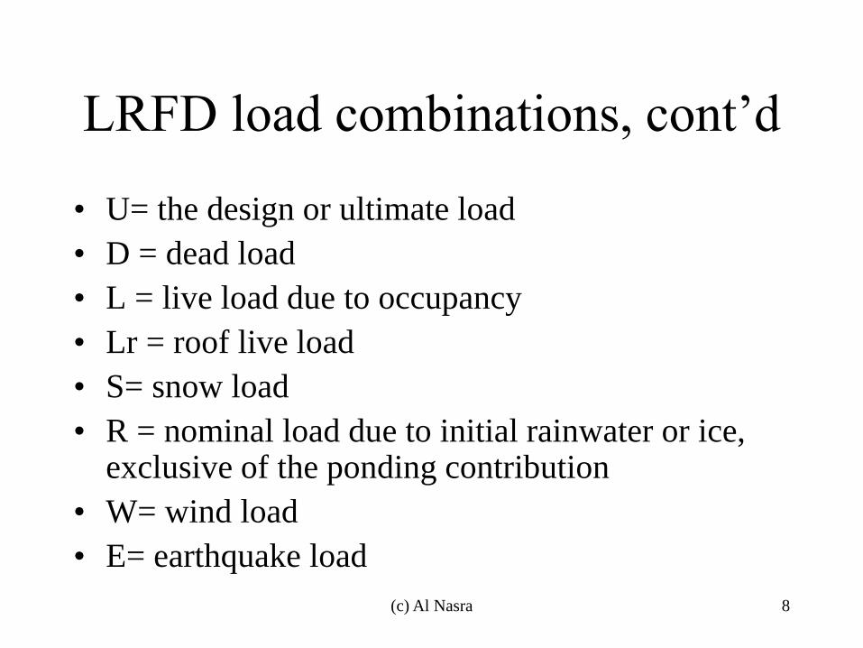
LRFD load combinations, cont’d
• U= the design or ultimate load
• D = dead load
• L = live load due to occupancy
• Lr = roof live load
• S= snow load
• R = nominal load due to initial rainwater or ice, exclusive of the ponding contribution
• W= wind load
• E= earthquake load
8 (c) Al Nasra

Example, Load combination
» W12X120, 10’ O.C
– Floor system has W12X120 beams spaced 10 ft on
center and is supporting a floor dead load of 60 psf, and
a live load of 100 psf. Determine the governing load in
lb/ft that each beam must support.
9 (c) Al Nasra
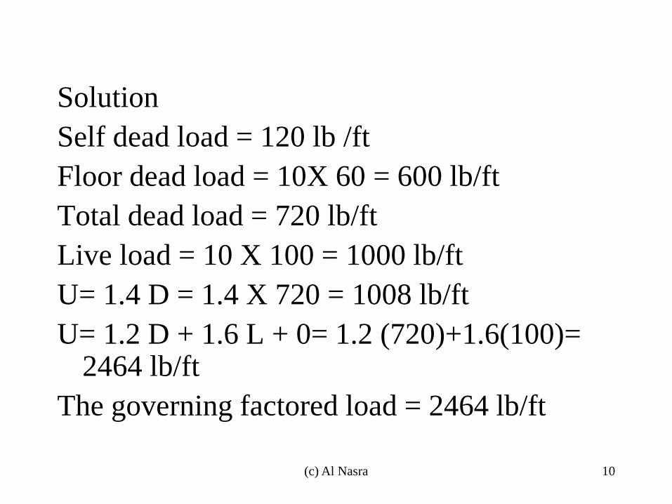
Solution
Self dead load = 120 lb /ft
Floor dead load = 10X 60 = 600 lb/ft
Total dead load = 720 lb/ft
Live load = 10 X 100 = 1000 lb/ft
U= 1.4 D = 1.4 X 720 = 1008 lb/ft
U= 1.2 D + 1.6 L + 0= 1.2 (720)+1.6(100)= 2464 lb/ft
The governing factored load = 2464 lb/ft
10 (c) Al Nasra
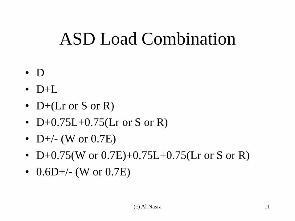
ASD Load Combination
• D
• D+L
• D+(Lr or S or R)
• D+0.75L+0.75(Lr or S or R)
• D+/- (W or 0.7E)
• D+0.75(W or 0.7E)+0.75L+0.75(Lr or S or R)
• 0.6D+/- (W or 0.7E)
11 (c) Al Nasra
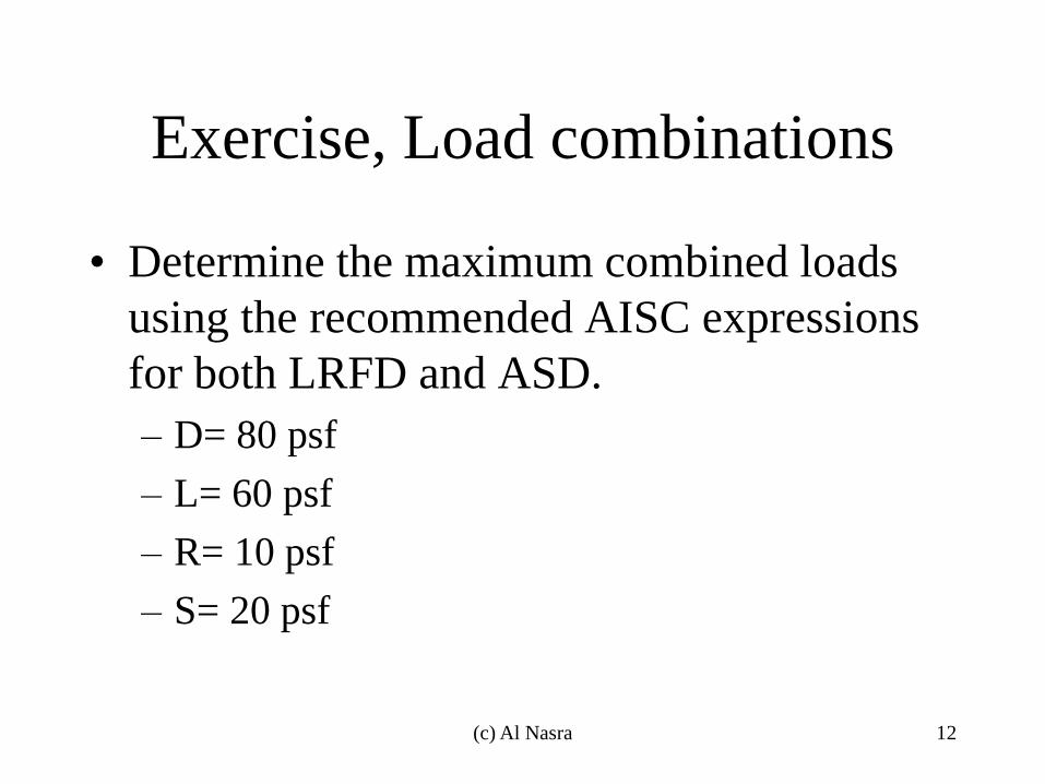
Exercise, Load combinations
• Determine the maximum combined loads
using the recommended AISC expressions
for both LRFD and ASD.
– D= 80 psf
– L= 60 psf
– R= 10 psf
– S= 20 psf
12 (c) Al Nasra
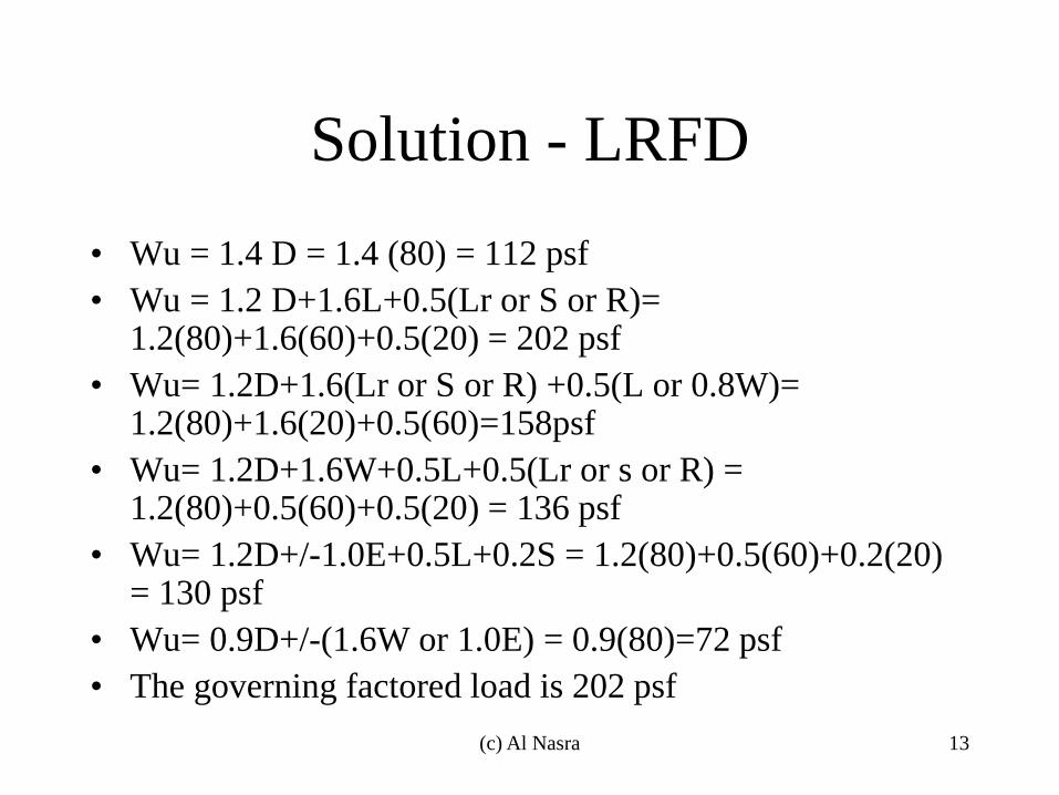
Solution - LRFD
• Wu = 1.4 D = 1.4 (80) = 112 psf
• Wu = 1.2 D+1.6L+0.5(Lr or S or R)= 1.2(80)+1.6(60)+0.5(20) = 202 psf
• Wu= 1.2D+1.6(Lr or S or R) +0.5(L or 0.8W)= 1.2(80)+1.6(20)+0.5(60)=158psf
• Wu= 1.2D+1.6W+0.5L+0.5(Lr or s or R) = 1.2(80)+0.5(60)+0.5(20) = 136 psf
• Wu= 1.2D+/-1.0E+0.5L+0.2S = 1.2(80)+0.5(60)+0.2(20) = 130 psf
• Wu= 0.9D+/-(1.6W or 1.0E) = 0.9(80)=72 psf
• The governing factored load is 202 psf
13 (c) Al Nasra
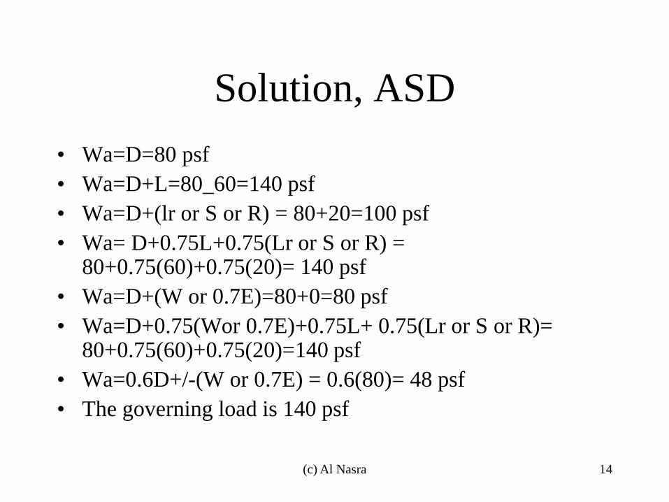
Solution, ASD
• Wa=D=80 psf
• Wa=D+L=80_60=140 psf
• Wa=D+(lr or S or R) = 80+20=100 psf
• Wa= D+0.75L+0.75(Lr or S or R) = 80+0.75(60)+0.75(20)= 140 psf
• Wa=D+(W or 0.7E)=80+0=80 psf
• Wa=D+0.75(Wor 0.7E)+0.75L+ 0.75(Lr or S or R)= 80+0.75(60)+0.75(20)=140 psf
• Wa=0.6D+/-(W or 0.7E) = 0.6(80)= 48 psf
• The governing load is 140 psf
14 (c) Al Nasra

(c) Al Nasra 15
Analysis of Tension Members
Moayyad Al Nasra, Ph.D, PE
(c) Al Nasra 16
Analysis of Tension Members
• Types of tension members:
– L- section,
– round bars,
– flat bars,
– double-angle,
– T-section,
– I-section,
– built-up
(c) Al Nasra 17
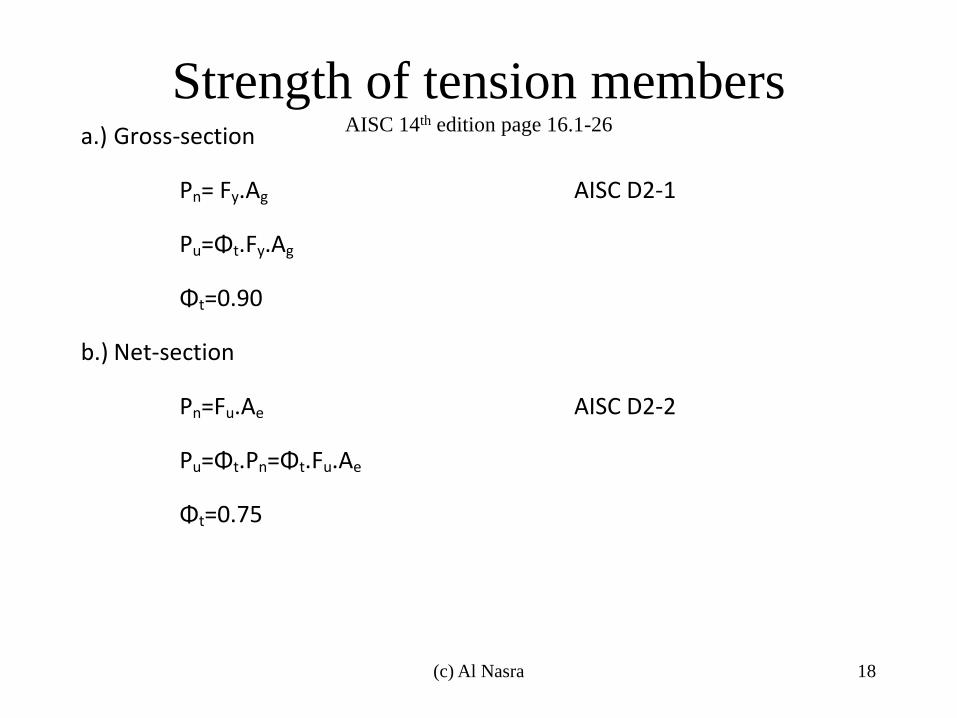
Strength of tension members AISC 14th edition page 16.1-26
a.) Gross-section
Pn= Fy.Ag AISC D2-1
Pu=Φt.Fy.Ag
Φt=0.90
b.) Net-section
Pn=Fu.Ae AISC D2-2
Pu=Φt.Pn=Φt.Fu.Ae
Φt=0.75
(c) Al Nasra 18
The design strength of a tension member
Φt.Pn, is to be the smaller of the above equations
Where:
Pn = nominal tensile force
Pu = ultimate tensile strength
Fy = yield stress
Fu = ultimate stress
Ae = effective area
Ag = gross area
(c) Al Nasra 19
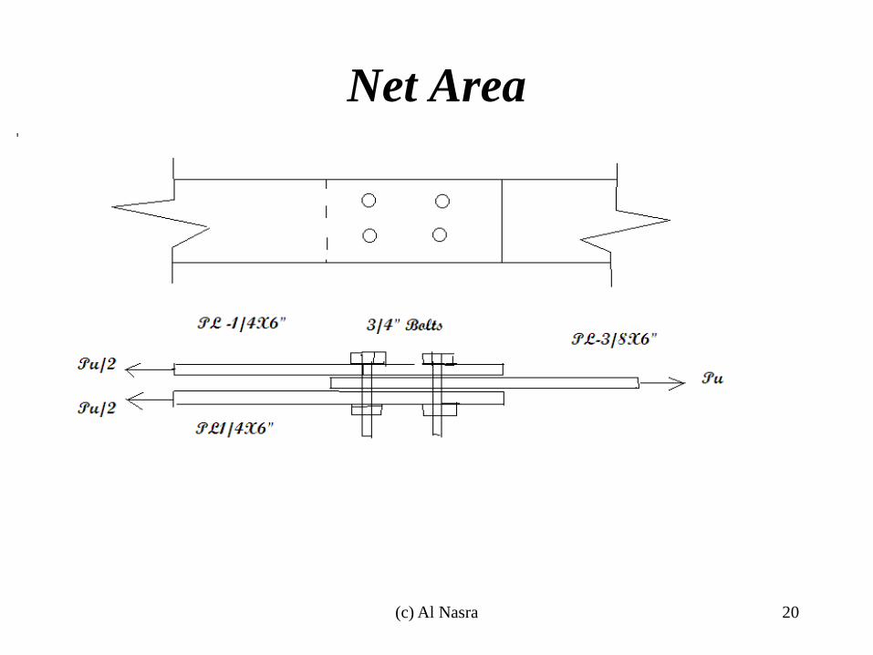
Net Area
(c) Al Nasra 20
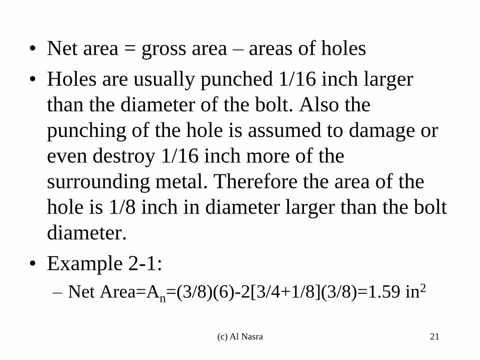
• Net area = gross area – areas of holes
• Holes are usually punched 1/16 inch larger
than the diameter of the bolt. Also the
punching of the hole is assumed to damage or
even destroy 1/16 inch more of the
surrounding metal. Therefore the area of the
hole is 1/8 inch in diameter larger than the bolt
diameter.
• Example 2-1:
– Net Area=An=(3/8)(6)-2[3/4+1/8](3/8)=1.59 in2
(c) Al Nasra 21
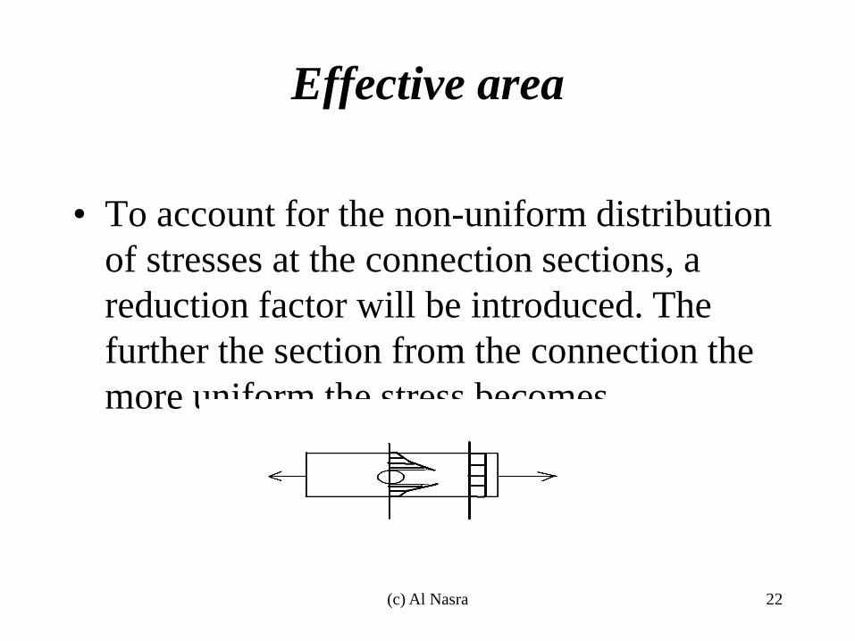
Effective area
• To account for the non-uniform distribution
of stresses at the connection sections, a
reduction factor will be introduced. The
further the section from the connection the
more uniform the stress becomes
(c) Al Nasra 22
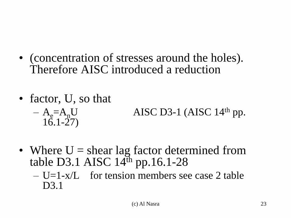
• (concentration of stresses around the holes). Therefore AISC introduced a reduction
• factor, U, so that – Ae=AnU AISC D3-1 (AISC 14th pp.
16.1-27)
• Where U = shear lag factor determined from table D3.1 AISC 14th pp.16.1-28 – U=1-x/L for tension members see case 2 table
D3.1
(c) Al Nasra 23
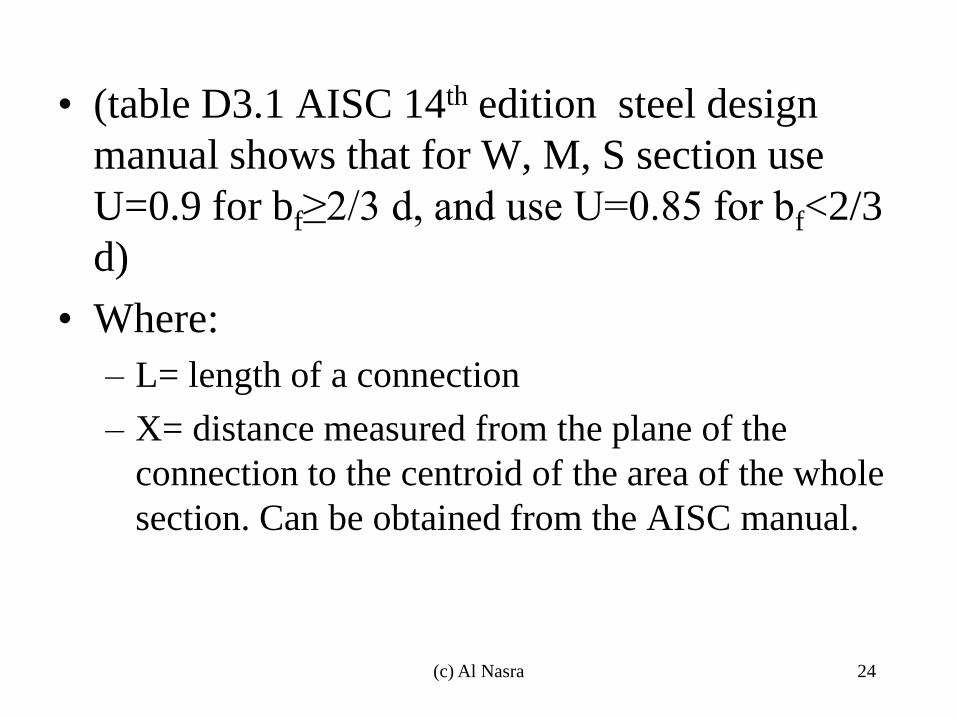
• (table D3.1 AISC 14th edition steel design
manual shows that for W, M, S section use
U=0.9 for bf≥2/3 d, and use U=0.85 for bf<2/3
d)
• Where:
– L= length of a connection
– X= distance measured from the plane of the
connection to the centroid of the area of the whole
section. Can be obtained from the AISC manual.
(c) Al Nasra 24
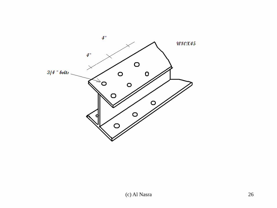
• Example: Determine the LRFD tensile
strength of a W10X45 with two lines of ¾
inch bolts in each flange using A572 grade
50 steel, with Fy=50 ksi, and Fu = 65 ksi,
and the AISC specification. There are
assumed to be at least three bolts in each
line 4 inches on center, and the bolts are not
staggered with respect to each other.
(c) Al Nasra 25
(c) Al Nasra 26
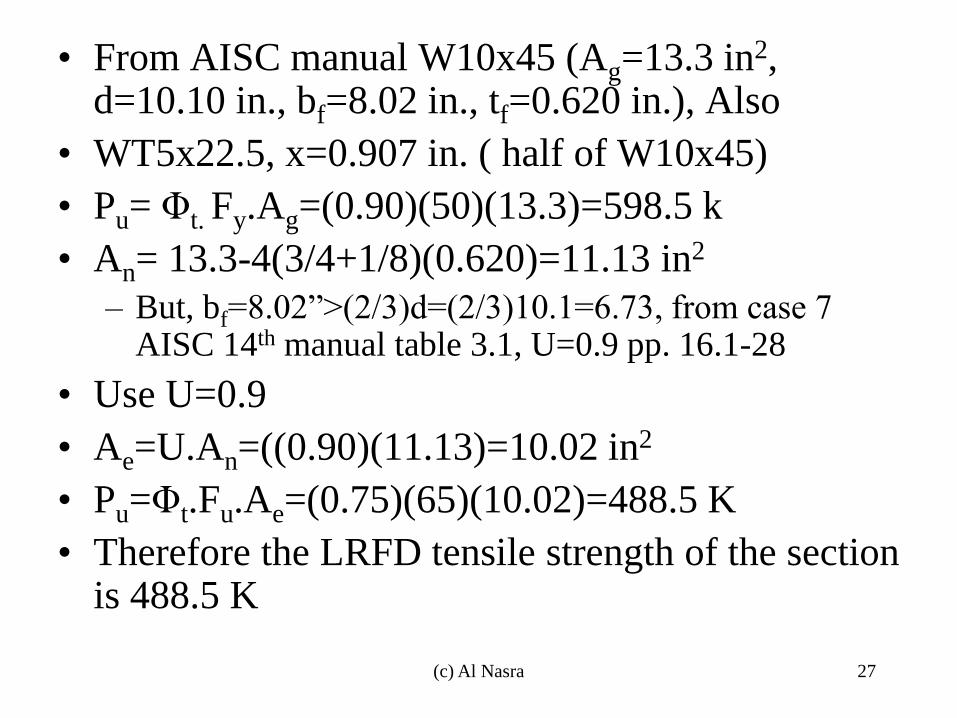
• From AISC manual W10x45 (Ag=13.3 in2, d=10.10 in., bf=8.02 in., tf=0.620 in.), Also
• WT5x22.5, x=0.907 in. ( half of W10x45)
• Pu= Φt. Fy.Ag=(0.90)(50)(13.3)=598.5 k
• An= 13.3-4(3/4+1/8)(0.620)=11.13 in2
– But, bf=8.02”>(2/3)d=(2/3)10.1=6.73, from case 7 AISC 14th manual table 3.1, U=0.9 pp. 16.1-28
• Use U=0.9
• Ae=U.An=((0.90)(11.13)=10.02 in2
• Pu=Φt.Fu.Ae=(0.75)(65)(10.02)=488.5 K
• Therefore the LRFD tensile strength of the section is 488.5 K
(c) Al Nasra 27
Bolted splice plates
• For bolted splice plates
• Ae=An≤0.85 Ag
• Example 2-2
• Same as example 2-1
• Ag=(3/8)(6)=2.25 in2
• 0.85Ag=0.85(2.25)=1.91 in2
• Ae=An=1.59 in2 < 0.85Ag=1.91 in2
(c) Al Nasra 28
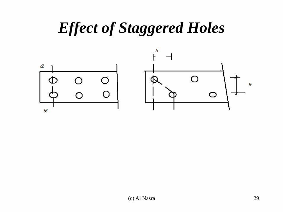
Effect of Staggered Holes
(c) Al Nasra 29

• The joint will fail at the weakest section
• To compute the net width of a tension
member along a zig-zag section:
– Net width=gross width-diameter of holes along
the zig-zag section + S2/(4g)
•
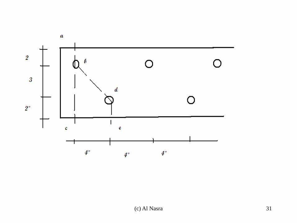
• Example Determine the critical net area of
¼ “ thick plate. The holes are punched for
¾” bolts
(c) Al Nasra 30
(c) Al Nasra 31

• Solution: Possible sections are abc, and abde.
• Hole diameters to be subtracted =3/4+1/8=7/8 in.
• Net width:
– Abc: 7-7/8 = 6.125 in.
– Abde: 7-2(7/8)+42/(4x3)=6.58 in.
• Therefore the section abc controls, net width=6.125
• Net area=An=6.125(1/4)=1.53 in2
(c) Al Nasra 32
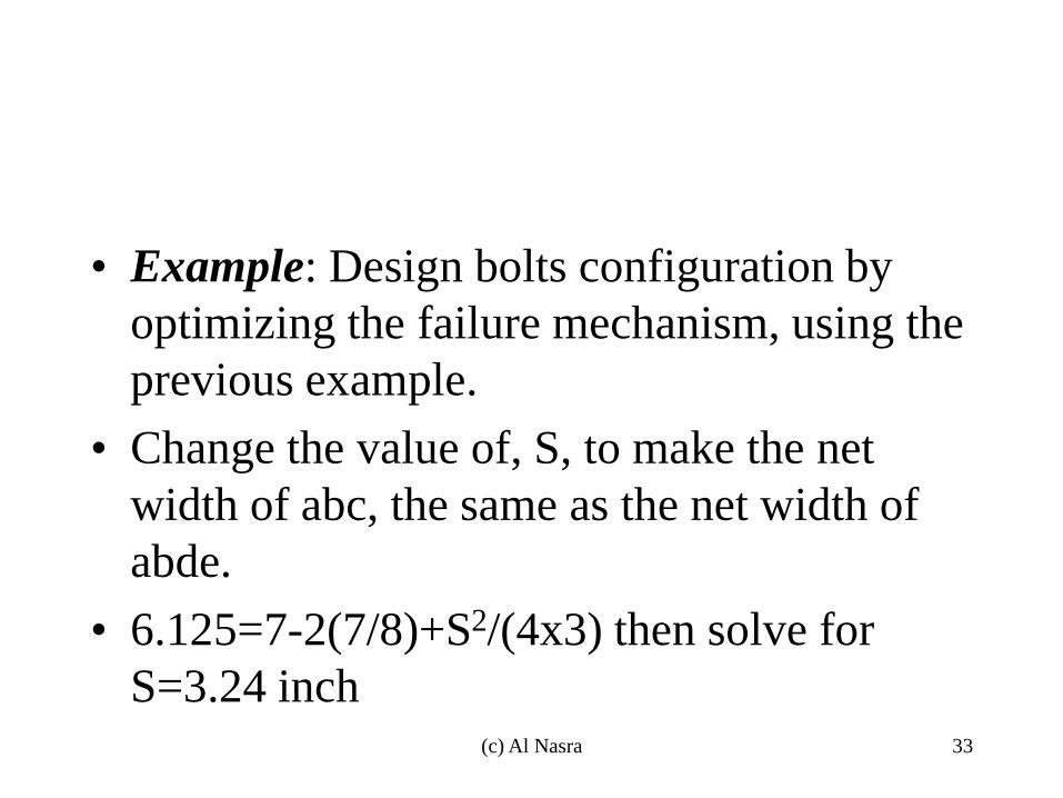
• Example: Design bolts configuration by
optimizing the failure mechanism, using the
previous example.
• Change the value of, S, to make the net
width of abc, the same as the net width of
abde.
• 6.125=7-2(7/8)+S2/(4x3) then solve for
S=3.24 inch
(c) Al Nasra 33

Net Area • In General
– bn=b – Σ dh + Σ (s2/4g)
b dh
s
g
(c) Al Nasra 34
Net Area
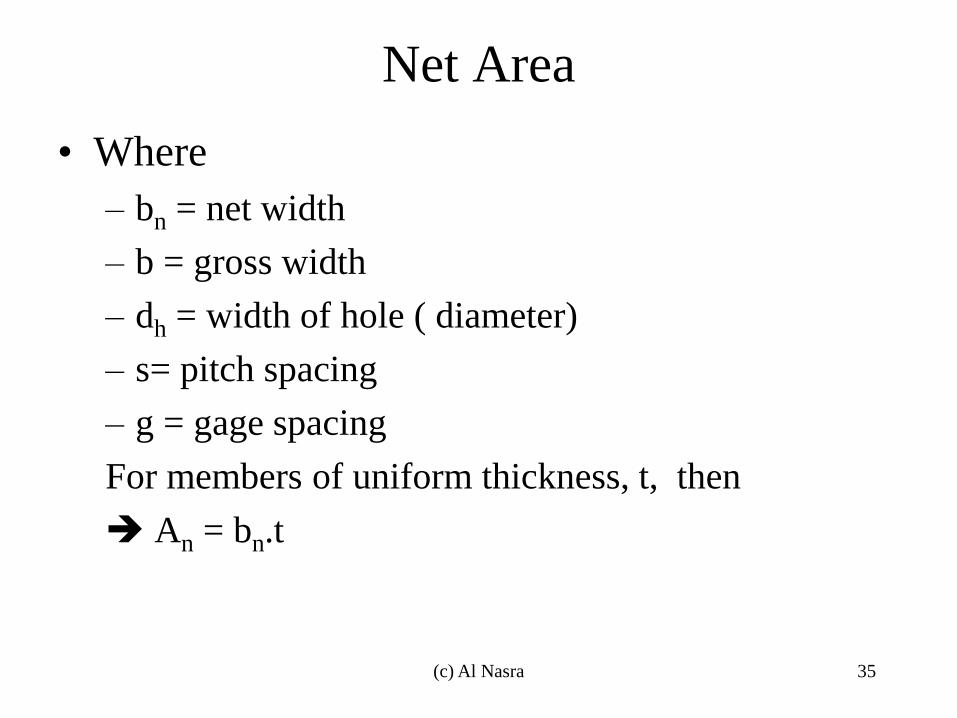
• Where
– bn = net width
– b = gross width
– dh = width of hole ( diameter)
– s= pitch spacing
– g = gage spacing
For members of uniform thickness, t, then
An = bn.t
(c) Al Nasra 35
Net Area
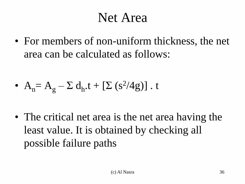
• For members of non-uniform thickness, the net
area can be calculated as follows:
• An= Ag – Σ dh.t + [Σ (s2/4g)] . t
• The critical net area is the net area having the
least value. It is obtained by checking all
possible failure paths
(c) Al Nasra 36
Net Area, Example
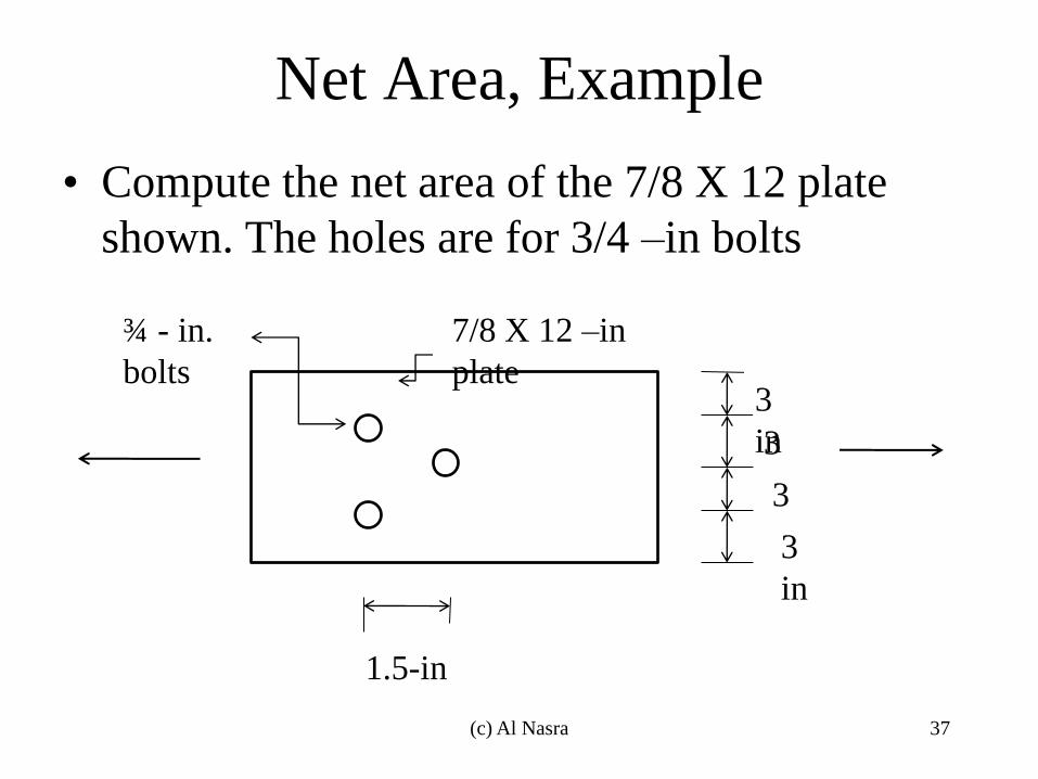
• Compute the net area of the 7/8 X 12 plate
shown. The holes are for 3/4 –in bolts
3
in
3
in
3
in 3
in
1.5-in
¾ - in.
bolts
7/8 X 12 –in
plate
(c) Al Nasra 37
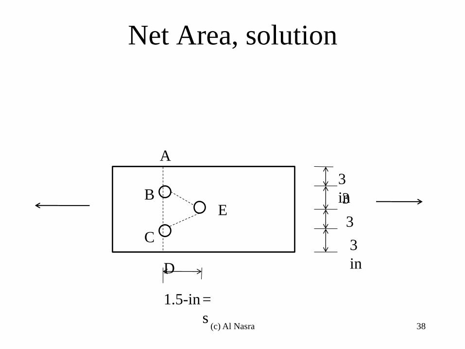
Net Area, solution
3
in
3
in
3
in 3
in
1.5-in
A
B
C
D
E
=
s (c) Al Nasra 38
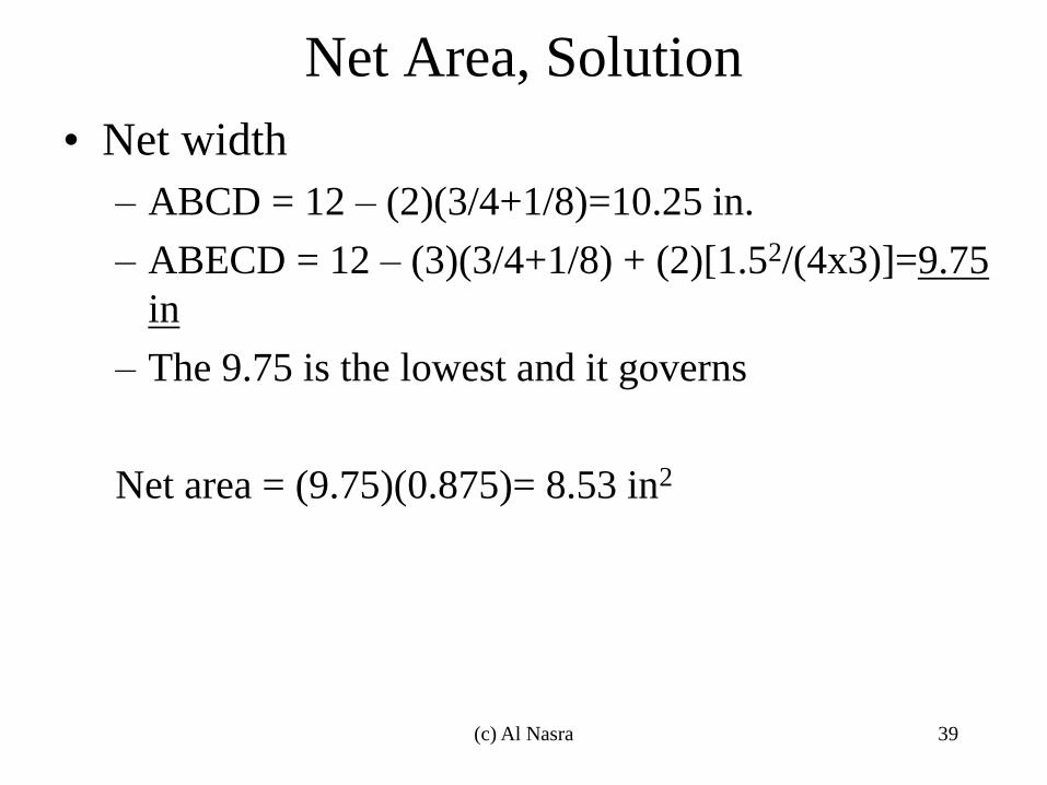
Net Area, Solution
• Net width
– ABCD = 12 – (2)(3/4+1/8)=10.25 in.
– ABECD = 12 – (3)(3/4+1/8) + (2)[1.52/(4x3)]=9.75
in
– The 9.75 is the lowest and it governs
Net area = (9.75)(0.875)= 8.53 in2
(c) Al Nasra 39
Slenderness Ratio
• The AISC steel design manual specification D1 lists a preferred (but not required) maximum slenderness ration (SR) of 300. Rods and wires are excluded from this recommendation,
• SR=l/r
• l= un-braced length
• r= radius of gyration = sqrt(I/A)
• I= moment of inertia
• A= cross-sectional area (c) Al Nasra 40
Block Shear
• The formulae used by LRFD (Φt.Pn) and
ASD (Pn/Ωt) to calculate the allowable
strengths of tension members are not always
the controlling criteria. The allowable
strength in tension may be controlled by
block shear strength, where the failure may
occur along a path involving tension in one
plane and shear on a perpendicular plane.
So it is possible for a block of steel to tear
out. (c) Al Nasra 41
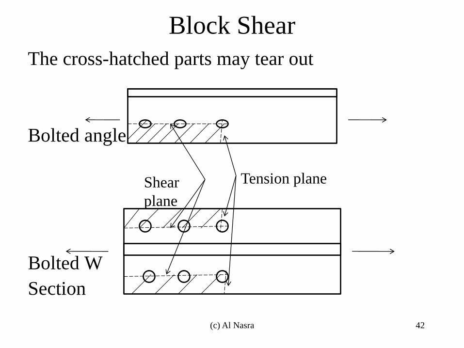
Block Shear
The cross-hatched parts may tear out
Bolted angle
Bolted W
Section
Shear
plane
Tension plane
(c) Al Nasra 42
Block Shear • The AISC specifications (J4.3) states that the
block shear design strength of a particular member is to be determined by
– Computing the tensile fracture strength on the net section in one direction and adding to that value the shear yield strength on the gross area on the perpendicular segment
– Computing the shear fracture strength on the gross area subject to tension and adding it to the tensile yield strength on the net area subject to shear on the perpendicular segment. The expression to apply is the one with the larger rupture term
(c) Al Nasra 43
Block Shear
• The AISC specification (J4.3) states that the available strength, Rn, for the block shear rupture design strength is as follows:
• Rn=0.6FuAnv+UbsFuAnt ≤ 0.6FyAgv+UbsFuAnt (AISC 14th ed. Eq. J4-5,pp. 16.1-129 )
• Φ =0.75 (LRFD), Ω = 2.00 (ASD)
• In which
– Anv =net area subjected to shear, in2 (mm2)
– Ant = net area subjected to tension, in2 (mm2)
– Agv = gross area subjected to shear, in2 (mm2)
(c) Al Nasra 44
Shear Block • To account for the fact that stress distribution may
not be uniform on the tensile plane for some connections, AISC introduced a reduction factor, Ubs. Should the tensile stress distribution be uniform, Ubs. = 1.0 according to AISC specification (J4.3) (i.e. gusset plates, single-row beam connection,…). For non-uniform stress tensile stresses, Ubs. =0.5 (i.e. multiple-row beam end connection,…)
• Should the block shear strength of a connection be insufficient, it may be increased by increasing the edge distance and/or the bolt spacing.
(c) Al Nasra 45
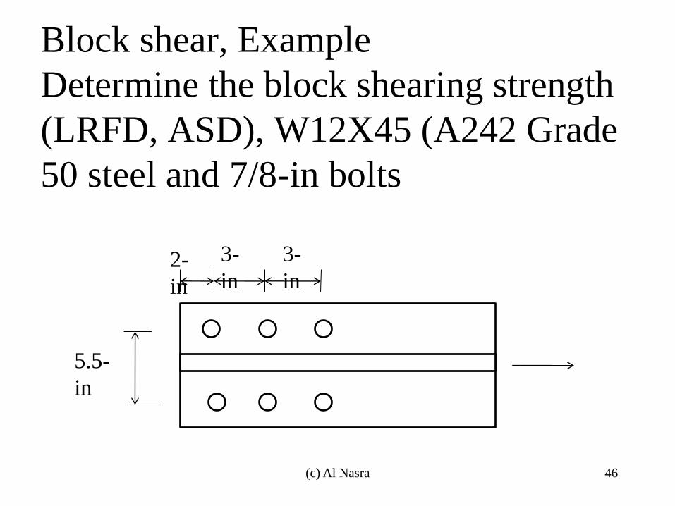
Block shear, Example
Determine the block shearing strength
(LRFD, ASD), W12X45 (A242 Grade
50 steel and 7/8-in bolts
2-
in
3-
in
3-
in
5.5-
in
(c) Al Nasra 46
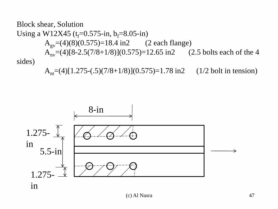
Block shear, Solution
Using a W12X45 (tf=0.575-in, bf=8.05-in)
Agv=(4)(8)(0.575)=18.4 in2 (2 each flange)
Anv=(4)[8-2.5(7/8+1/8)](0.575)=12.65 in2 (2.5 bolts each of the 4
sides)
Ant=(4)[1.275-(.5)(7/8+1/8)](0.575)=1.78 in2 (1/2 bolt in tension)
8-in
1.275-
in
5.5-in
1.275-
in
(c) Al Nasra 47
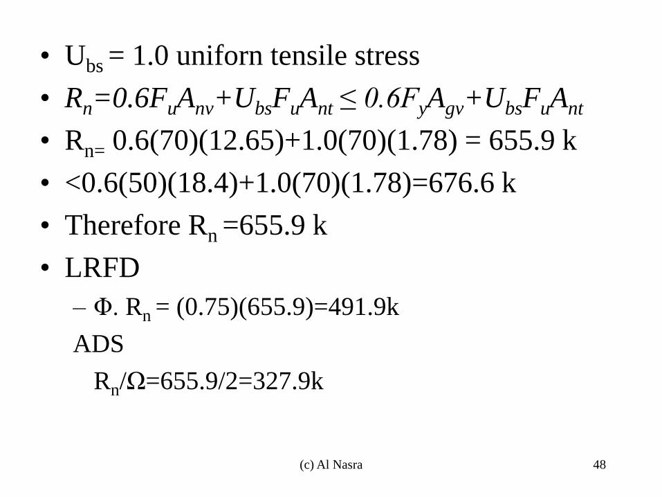
• Ubs = 1.0 uniforn tensile stress
• Rn=0.6FuAnv+UbsFuAnt ≤ 0.6FyAgv+UbsFuAnt
• Rn= 0.6(70)(12.65)+1.0(70)(1.78) = 655.9 k
• <0.6(50)(18.4)+1.0(70)(1.78)=676.6 k
• Therefore Rn =655.9 k
• LRFD
– Φ. Rn = (0.75)(655.9)=491.9k
ADS
Rn/Ω=655.9/2=327.9k
(c) Al Nasra 48