Control of Vibrations due to Moving Loads on Suspension ... · Control of Vibrations due to Moving...
26
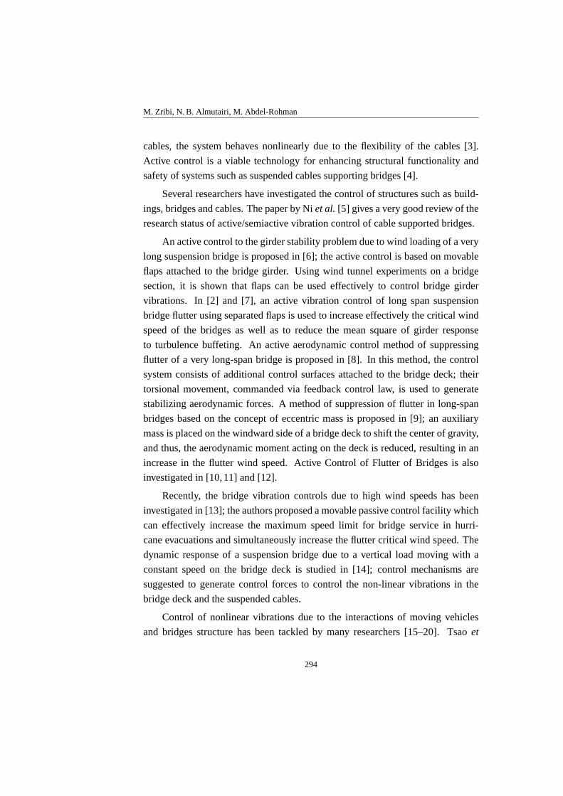
Nonlinear Analysis: Modelling and Control, 2006, Vol. 11, No. 3, 293–318 Control of Vibrations due to Moving Loads on Suspension Bridges M. Zribi, N. B. Almutairi, M. Abdel-Rohman College of Engineering and Petroleum, Kuwait University P.O. Box 5969, Safat-13060, Kuwait [email protected] Received: 31.03.2006 Revised: 04.07.2006 Published online: 01.09.2006 Abstract. The flexibility and low damping of the long span suspended cables in suspension bridges makes them prone to vibrations due to wind and moving loads which affect the dynamic responses of the suspended cables and the bridge deck. This paper investigates the control of vibrations of a suspension bridge due to a vertical load moving on the bridge deck with a constant speed. A vertical cable between the bridge deck and the suspended cables is used to install a hydraulic actuator able to generate an active control force on the bridge deck. Two control schemes are proposed to generate the control force needed to reduce the vertical vibrations in the suspended cables and in the bridge deck. The proposed controllers, whose design is based on Lyapunov theory, guarantee the asymptotic stability of the system. The MATLAB software is used to simulate the performance of the controlled system. The simulation results indicate that the proposed controllers work well. In addition, the performance of the system with the proposed controllers is compared to the performance of the system controlled with a velocity feedback controller. Keywords: suspension bridges, moving loads, vibration control. 1 Introduction Long steel suspended cables such as the ones used in suspension bridges and electric transmission lines are prone to vibration induced by wind and vertical loads [1] and [2]. Suspended cables supporting bridges (see Fig. 1) are tensioned due to the weight of the bridge deck, the traffic loading, and their own weights. When the suspended cables are subjected to any disturbance due to wind or ver- tical loads, and due to the coupling between the bridge deck and the suspended 293
Transcript of Control of Vibrations due to Moving Loads on Suspension ... · Control of Vibrations due to Moving...
Nonlinear Analysis: Modelling and Control, 2006, Vol. 11, No. 3, 293–318
Control of Vibrations due to Moving Loadson Suspension Bridges
M. Zribi, N. B. Almutairi, M. Abdel-Rohman
College of Engineering and Petroleum, Kuwait UniversityP. O. Box 5969, Safat-13060, Kuwait
Received:31.03.2006 Revised:04.07.2006 Published online: 01.09.2006
Abstract. The flexibility and low damping of the long span suspended cablesin suspension bridges makes them prone to vibrations due to wind and movingloads which affect the dynamic responses of the suspended cables and the bridgedeck. This paper investigates the control of vibrations of asuspension bridgedue to a vertical load moving on the bridge deck with a constant speed. Avertical cable between the bridge deck and the suspended cables is used toinstall a hydraulic actuator able to generate an active control force on the bridgedeck. Two control schemes are proposed to generate the control force needed toreduce the vertical vibrations in the suspended cables and in the bridge deck. Theproposed controllers, whose design is based on Lyapunov theory, guarantee theasymptotic stability of the system. The MATLAB software is used to simulatethe performance of the controlled system. The simulation results indicate thatthe proposed controllers work well. In addition, the performance of the systemwith the proposed controllers is compared to the performance of the systemcontrolled with a velocity feedback controller.
Keywords: suspension bridges, moving loads, vibration control.
1 Introduction
Long steel suspended cables such as the ones used in suspension bridges and
electric transmission lines are prone to vibration induced by wind and vertical
loads [1] and [2]. Suspended cables supporting bridges (see Fig. 1)are tensioned
due to the weight of the bridge deck, the traffic loading, and their own weights.
When the suspended cables are subjected to any disturbance due to wind or ver-
tical loads, and due to the coupling between the bridge deck and the suspended
293
M. Zribi, N. B. Almutairi, M. Abdel-Rohman
cables, the system behaves nonlinearly due to the flexibility of the cables [3].
Active control is a viable technology for enhancing structural functionality and
safety of systems such as suspended cables supporting bridges [4].
Several researchers have investigated the control of structures such as build-
ings, bridges and cables. The paper by Niet al.[5] gives a very good review of the
research status of active/semiactive vibration control of cable supported bridges.
An active control to the girder stability problem due to wind loading of a very
long suspension bridge is proposed in [6]; the active control is based on movable
flaps attached to the bridge girder. Using wind tunnel experiments on a bridge
section, it is shown that flaps can be used effectively to control bridge girder
vibrations. In [2] and [7], an active vibration control of long span suspension
bridge flutter using separated flaps is used to increase effectively the critical wind
speed of the bridges as well as to reduce the mean square of girder response
to turbulence buffeting. An active aerodynamic control method of suppressing
flutter of a very long-span bridge is proposed in [8]. In this method, the control
system consists of additional control surfaces attached to the bridge deck; their
torsional movement, commanded via feedback control law, is used to generate
stabilizing aerodynamic forces. A method of suppression of flutter in long-span
bridges based on the concept of eccentric mass is proposed in [9]; an auxiliary
mass is placed on the windward side of a bridge deck to shift the center of gravity,
and thus, the aerodynamic moment acting on the deck is reduced, resulting in an
increase in the flutter wind speed. Active Control of Flutter of Bridges is also
investigated in [10,11] and [12].
Recently, the bridge vibration controls due to high wind speeds has been
investigated in [13]; the authors proposed a movable passive control facility which
can effectively increase the maximum speed limit for bridge service in hurri-
cane evacuations and simultaneously increase the flutter critical wind speed. The
dynamic response of a suspension bridge due to a vertical load moving with a
constant speed on the bridge deck is studied in [14]; control mechanisms are
suggested to generate control forces to control the non-linear vibrations in the
bridge deck and the suspended cables.
Control of nonlinear vibrations due to the interactions of moving vehicles
and bridges structure has been tackled by many researchers [15–20]. Tsaoet
294

Control of Vibrations due to Moving Loads on Suspension Bridges
al. proposed a system model representation for general multiple moving lumped-
parameter systems interacting with a distributed-parameter systems and applied
it to the vehicle-bridge interaction problem. The main aspect of this work is
that the form of the linear parameter varying system developed allows us to con-
sider the analysis and control design using the theoretical results in this field.
In [19], Karoumi uses finite element method to model and analyze the cable-
stayed bridges under the action of moving vehicles. In [17], the effect of using
semi-active control strategy in vehicle suspensions on the coupled vibrations of
a vehicle traversing a bridge is examined and a various designs of suspension
systems for bridge-friendly vehicle are proposed. Recently, an intensive analysis
and experimental work has been done to evaluate the load bearing capacityof
the historic suspension bridges so that traffic loads are managed to ensure their
continued safe operation [21,22].
Benchmark problems in structural control have provided a mean for resear-
chers and designers to assess the merits of various control strategies ona single
problem with a common set of performance criteria. The first generation of
benchmark problems for bridges was based on the cable-stayed bridge inCape
Girardeau, Missouri, USA. The first phase of the benchmark problem considers
the simplest case of excitation which is a uniform excitation in the longitudinal di-
rection of the bridge [23,24]. This problem has been tackled by many researchers
and different controllers have been proposed to solve this problem [25–28]. In the
second phase of the benchmark cable-stayed bridge problem, the complexity of
the excitation is increased. Multiple support excitation with different angles and
times of arrival for each support is considered. Additionally, an alternate model
is developed to study the robust stability and performance of the control system
under realistic conditions. Here the mass of the bridge is incremented due to
snow and rain loads [29, 30]. Different controllers have been proposed to solve
such a problem that can be found in [31–34]. This paper shows the design of two
control schemes to control the nonlinear vibrations in the suspended cableand the
bridge deck due to vertical load moving on the bridge deck with a constant speed.
Numerical example is used to show the effectiveness of the proposed controllers.
Practical implementation will be the focus of one of our future research. The first
control scheme is an optimal state feedback controller while the second control
295

M. Zribi, N. B. Almutairi, M. Abdel-Rohman
scheme is a robust state feedback controller whose design is based on design of
optimal controllers. In order to control the nonlinear vibrations in the suspended
cable and the bridge deck, one may install a vertical cable between the bridge deck
and the suspended cable to install a hydraulic actuator able to generate an active
feedback control force.
This paper investigates the control of vibrations due to moving loads on
suspension bridges. In order to control the nonlinear vibrations in the bridge deck,
one may install a vertical cable between the bridge deck and the suspendedcable
to install a hydraulic actuator able to generate an active feedback controlforce.
The design of the control force to greatly reduce the vertical vibrations inthe
suspended cables and the vertical vibrations in the bridge deck is discussed in this
paper.
The rest of the paper is organized as follows. The dynamic model of a suspen-
sion bridge interacting with a moving load is presented in Section 2. A nonlinear
controller to reduce the vibrations of the system is proposed in Section 3. A
linear controller to reduce the vibrations of the system is presented in Section4.
Simulation results of the proposed control schemes are presented and discussed
in Section 5. Finally, the conclusion is given in Section 6.
In the sequel, we denote byW T the transpose of a matrix or a vectorW .
We useW > 0 (W < 0) to denote a positive- (negative-) definite matrixW .
Sometimes, the arguments of a function will be omitted in the analysis when no
confusion can arise.
2 Dynamic model of the suspension bridge system
The basic equations of motion of the suspended cables (see Fig. 1) are defined
in [35, 36] and [37]. According to the displacements directions defined in Fig. 2,
the general equations of motion are:
∂
∂s
[
(To + τ)∂(x+ U)
∂s
]
= m∂2U
∂t2,
∂
∂s
[
(To + τ)∂(y + V )
∂s
]
= −mg +m∂2V
∂t2+ c
∂V
∂t+ Fv(s, t), (1)
∂
∂s
[
(To + τ)∂W
∂s
]
= m∂2W
∂t2+ c
∂W
∂t+ Fw(s, t),
296

Control of Vibrations due to Moving Loads on Suspension Bridges
wheres is the spatial coordinate along the cable curved length;t is the time;x(s)
is the horizontal coordinate along the cable span;y(s) is the cable static profile;
U(s, t) is the displacement in the tangential direction of the cable;V (s, t) is the
displacement in the vertical direction of the cable;W (s, t) is the displacement in
the transversal direction of the cable;To is the static tension in the cable;τ is the
additional dynamic tension in the cable;g is the gravitational acceleration;c is
the damping coefficient in the cable;m is the mass of the cable per unit length;
Fv(s, t) is the external loading per unit length in the vertical direction;Fw(s, t) is
the external loading per unit length in the transverse direction.
Fig. 1. Suspension bridge.
Fig. 2. Displacements directions of suspended cables.
The nonlinear strain-displacement relationship during the deformation of the
cable is given by:
τ
E A=d s
′
− d s
d s, (2)
whereE is the modulus of elasticity, andA is the cross section area of the cable.
297
M. Zribi, N. B. Almutairi, M. Abdel-Rohman
The deformed cable segment,ds′
, and the un-deformed cable segment,ds are
defined as,
d s′2 = (d x+ ∂U)2 + (d y + ∂V )2 + (∂W )2,
d s2 = d x2 + d y2.(3)
Equations (1) can be simplified [36] based on the assumption of a small curva-
ture regime and condensing the longitudinal displacementU in the case of zero
longitudinal loading which leads to:
(1 + αe)ToLV′′
(s, t) + αβToe+ LFv(s, t) = mL ¨V (s, t) + cL ˙V (s, t),
(1 + αe)ToLW′′
(s, t) + LFw(s, t) = mL ¨W (s, t) + cL ˙W (s, t), (4)
e = −βV (s, t)
L+
1
2
[
V′2(s, t) + W
′2(s, t)
]
.
In equations (4), the prime indicates differentiation with respect tos (the spatial
coordinate along the cable curved length) and the dot indicates differentiation with
respect to timet. Also,L is the length of the suspended cables, and the parameters
α andβ are defined such as,
α =EA
To
and β =mgL
To
. (5)
When the suspended cables are supporting a bridge deck, the equationsof motion
become:
(1 + αe)ToLV′′
+ αβToe+ LKc(z − V ) + Tou(t) = mL ¨V + cL ˙V,
(1 + αe)ToLW′′
+ LFw(s, t) = mL ¨W + cL ˙W,
EI∂4z
∂x4+mb
∂2z
∂t2+cb
∂z
∂t= −Kc(z−V ) − u(t)δ(x−xp) + Pδ(x−xp),
e = −βV
L+
1
2
[
V′2 + W
′2]
.
(6)
The termKc(z − V ) in equations (6) was used to represent the vertical load
Fv(s, t) in equations (4) and it represents the distributed vertical force in the
vertical hangers. Also,z(x, t) is the vertical displacement of the bridge deck;
Kc is the stiffness of the vertical cables which hang the bridge deck;mb is the
mass of the bridge deck;cb is the damping coefficient of the bridge deck;EI is
298

Control of Vibrations due to Moving Loads on Suspension Bridges
the flexural rigidity of the bridge deck;P is the magnitude of the moving load;
xp is the location of the moving load at any timet from the left support;δ is the
Dirac delta function which is used to introduce the concentrated moving load on
the differential equation;u(t) is the active control force.
The displacement functionsW (s, t), V (s, t) andz(x, t) are considered to be
the contribution of the first modes of vibrations. Therefore they are assumed as
follows:
W (s, t) = ψ(s)W (t),
V (s, t) = φ(s)V (t),
z(x, t) = η(x)B(t),
(7)
whereW (t) is the transverse displacement of the suspended cable;V (t) is the
vertical displacement of the suspended cable;B(t) is the vertical displacement
of the bridge deck;φ(s) andψ(s) are the first mode shapes in the vertical and
transversal directions, respectively;η(s) is the first mode shape for the bridge
deck.
The modesψ(s), φ(s) can be determined using linear theory of cables and to
satisfy the boundary conditions [35] which provide:
ψ(s) = sinπ s
L, (8)
φ(s) = Ko
(
1 − tanµπ
2sin
µπ s
L− cos
µπ s
L
)
, (9)
whereKo is a constant chosen to makeφ(L2) = 1 andµ is a constant which fits
with the boundary conditions.
For a two hinged bridge deck, the mode shapeη(x) can be assumed as:
η(x) = sinπx
L. (10)
Substituting equations (7)–(10) into equations (6) and applying an integral
transformation one obtains, respectively, the equations of motion of the suspended
cable in the vertical and the transverse directions and the vertical motion of the
299
M. Zribi, N. B. Almutairi, M. Abdel-Rohman
bridge deck as follows:
V + 2ζωvV + ω2
vV + c1V2 + c2W
2 + c3V3 + c4VW
2
= d1V + d2B + κ1u(t) + fv(t),
W + 2ζωwW + ω2
wW + c5VW + c6V2W + c7W
3 = fw(t),
B + 2ζbωbB + ω2
bB = d3V + d4B + κ2u(t) + P ∗ sin(v t),
(11)
whereωv is the natural frequency of the cable in the vertical direction, and it is
defined in Appendix;ωw is the natural frequency of the cable in the transversal
direction, and it is defined in Appendix;ωb is the natural frequency of the bridge
deck, and it is defined in Appendix;ζ is the damping ratio in the suspended cable;
ζb is the damping ratio in the bridge deck;P ∗ = 2PmbL
, whereP is the magnitude
of the moving load;x is the location of the control forceu(t) with respect to the
origin of x-axis;v is the speed of the moving load. The scalarsc1, c2, c3, . . . , c7,
d1, d2, d3, d4, κ1 andκ2 are constants which are defined in Appendix.
The forcesfv(t), andfw(t) are such,
fv(t) =
−L∫
0
φFv(x, t)dx
mL∫
0
φ2dx
, fw(t) =
−L∫
0
ψFw(x, t)dx
mL∫
0
ψ2dx
. (12)
Define the following state variables:
x1(t) = V (t), x2(t) = V (t), x3(t) = B(t),
x4(t) = B(t), x5(t) = W (t), x6(t) = W (t).(13)
Hence, the equations of a suspension bridge interacting with a moving load
can be written in state-space form as follows:
x(t) = Ax(t) +Bu(t) + gx
(
x(t))
+ d(t), (14)
where
A =
0−ω2
v + d1
0d3
01
1−2ζωv
0000
0d2
0−ω2
b + d4
00
001
−2ζbωb
00
00000
−ω2w
00001
−2ζωw
,
300

Control of Vibrations due to Moving Loads on Suspension Bridges
x =
x1
x2
x3
x4
x5
x6
, B =
0κ1
0κ2
00
, d(t) =
0fv(t)
0P ∗ sin(v t)
0fw(t)
,
gx(x) =
0−c1x
21− c2x
25− c3x
31− c4x1x
25
000
−x1 − c5x1x5 − c6x21x5 − c7x
35
.
Let
g(x, t) = gx(x) + d(t). (15)
Hence the equations of the system in (14) can be written as,
x = Ax +Bu+ g(x, t). (16)
Simulations results of the uncontrolled system show that it is a stable sys-
tem. Also, the simulations indicate that the response of the system oscillates.
Therefore, the objective of this paper is to design control schemes to improve the
stability of the system by reducing the oscillations.
Remark 1. The simulation results indicate that the nonlinear functiong(x, t) in
(15) is uniformly bounded and hence it can be assumed that the nonlinear term
g(x, t) satisfies the following cone-bounding constraint,
∥
∥g(x, t)∥
∥ ≤ µ∥
∥
x(t)∥
∥, (17)
whereµ is a positive scalar.
Remark 2. It can be checked that the pair (A, B) in (16) is controllable. Hence
the poles of the closed loop system can be selected such that the responseof the
linear part of the system (i.e.,g(x, t) = 0) is as desired.
301
M. Zribi, N. B. Almutairi, M. Abdel-Rohman
3 Design of the first control scheme
In this section, a nonlinear controller is used to control the suspension bridge
system described by (16). The control law is divided into a linear part and a
nonlinear part. The linear part of the controller is designed by using the pole
placement technique. The nonlinear part of the controller is designed to guarantee
the asymptotic stability of the closed loop system.
Let the matrixAc be such that
Ac = A−BK (18)
and let the symmetric positive definite matrixP1 be the solution of the following
Lyapunov equation,
ATc P1 + P1Ac = −Q1, (19)
whereQ1 = QT1> 0.
Theorem 1. The control law given by(20)–(22) when applied to the suspension
bridge system(16)guarantees the asymptotic stability of the system.
u = uL + uN (20)
with
uL = −Kx (21)
and
uN = −ρ1 sign(BTP1x). (22)
Proof. Using (16), (20) and (21), it follows that
x = Ax +B(−Kx + uN ) + g(x, t)
= (A−BK)x +BuN + g(x, t)
= Acx +BuN + g(x, t).
(23)
Consider the following Lyapunov function candidate,
V1 = xTP1x. (24)
302

Control of Vibrations due to Moving Loads on Suspension Bridges
Note thatV1 > 0 for x 6= 0 andV1 = 0 for x = 0.Taking the derivative ofV1
with respect to time and using equations (23), (22), (19) and (17), it follows that
V = xTP1x + x
TP1x
=(
Acx +BuN + g(x, t))TP1x + x
TP1
(
Acx +BuN + g(x, t))
= xT (AT
c P1 + P1Ac)x + 2xTP1BuN + 2g(x, t)TP1x
= −xTQ1x + 2xTP1BuN + 2g(x, t)TP1x
≤ −λmin(Q1)‖x‖2 + 2µλmax(P1)‖x‖
2 − 2ρ1xTP1B
BTP1x
|BTP1x|
= −λmin(Q1)‖x‖2 + 2µλmax(P1)||x||
2 − 2ρ1|BTP1x|
≤ −(
λmin(Q1) − 2µλmax(P1))
‖x‖2.
(25)
Therefore, it can be concluded thatV < 0 if the matricesP1 andQ1 are selected
such that the conditionλmin(Q1)− 2µλmax(P1) > 0 . Hence the control scheme
given by (20)–(22) guarantees the asymptotic stability of the closed loop system.
4 Design of the second control scheme
In this section, a linear controller is designed to control the suspension bridge
system described by (16). Again, the control law is divided into two parts.The
first part of the controller is designed by using the pole placement technique as in
the previous section. The second part of the controller is designed to guarantee
the asymptotic stability of the closed loop system.
The matrixAc is such that
Ac = A−BK. (26)
Let the symmetric positive definite matrixP2 be the solution of the following
Lyapunov equation,
ATc P2 + P2Ac = −Q2, (27)
whereQ2 = QT2> 0.
Let the design parameterγ be such that
γ ≥λmax(P2)
λmin(P2BBTP2)µ. (28)
303

M. Zribi, N. B. Almutairi, M. Abdel-Rohman
Theorem 2. The control law given by(29)–(31) when applied to the suspended
cables system(16)guarantees the asymptotic stability of the system.
u = uL1+ uL2
(29)
with
uL1= −Kx (30)
and
uL2= −γBTP2x. (31)
Proof. Using (16), (29) and (30), it follows that
x = Ax +B(−Kx + uL2) + g(x, t)
= (A−BK)x +BuL2+ g(x, t)
= Acx +BuL2+ g(x, t).
(32)
Consider the following Lyapunov function candidate,
V2 = xTP2x. (33)
Note thatV2 > 0 for x 6= 0 andV2 = 0 for x = 0. Taking the derivative ofV2
with respect to time and using (32), (31) and (27), it follows that
V2 = xTP2x + x
TP2x
=(
Acx +BuL2+ g(x, t)
)TP2x + x
TP2
(
Acx +BuL2+ g(x, t)
)
= xT (AT
c P2 + P2Ac)x + 2g(x, t)TP2x + 2xTP2BuL2
= −xTQ2x + 2g(x, t)TP2x + 2xTP2BuL2
≤ −xTQ2x + 2µ‖P2x‖ ‖x‖ − 2γxTP2BB
TP2x
≤ −xTQ2x + 2µλmax(P2) ‖x‖
2 − 2γλmin(P2BBTP ) ‖x‖2
= −xTQ2x + 2
(
µλmax(P2) − γλmin(P2BBTP )
)
‖x‖2
≤ −xTQ2x.
(34)
The choice ofγ guarantees that(µλmax(P2) − γλmin(P2BBTP )) ≤ 0.
Therefore, it can be concluded thatV2 < 0. Hence the control scheme given
by (29)–(31) guarantees the asymptotic stability of the closed loop system.
304

Control of Vibrations due to Moving Loads on Suspension Bridges
5 Simulation results
The controllers designed in Sections 3 and 4 are simulated using the MATLAB
software.
The example in Abdel-Rohman and Spencer [1] is used for simulation pur-
poses. The example consists of a suspended cable of lengthL = 200 m, diameter
D = 10 cm, massmc = 62 Kg/m, tension in the cableTo = 2 × 10⁶ N, axial
stiffnessEA = 1.57 × 10⁹ N. The damping ratio of the cable is assumed to be
ζ = 0.1 %. The mass of the bridge deck ismb = 10000 kg/m, the damping
in the bridge isζb = 0.01. The vertical hangers stiffness is assumed to be
Kc = 106 N/m, the flexural rigidity is taken to beEI = 5 × 10¹⁰ Nm2. The
natural frequencies are such thatωw = 2.8 rps,ωv = 2.8 rps, andωb = 0.552 rps.
The parametersc1 – c7 are such thatc1 = 1.2196, c2 = 0.41, c3 = 0.578,
c4 = 0.56535, c5 = 0.8015, c6 = 0.5634, c7 = 0.55. The parametersd1 – d4
are such thatd1 = −Kc/m, d2 = Kc/m, d3 = Kc/mb, d4 = −Kc/mb. The
parametersκ1 andκ2 are such thatκ1 = 2
mL, κ2 = −2
mbL. The magnitude of the
moving load isP = 100000, andP ∗ = 2PmbL
. The speed of the moving load is
v = 10 m/s, and the location of the control forceu(t) is at0.5L.
Fig. 3 shows the vertical displacement of the suspended cable,V (t) when no
control is applied to the system; it can be seen that the response oscillates with
0 10 20 30 40 50 60 70 80 90 100−0.25
−0.2
−0.15
−0.1
−0.05
0
0.05
0.1
0.15
0.2
0.25
Time (sec)
Dis
plac
emen
t (m
)
Fig. 3. The vertical displacement of the suspended cable,V (t) with no control.
305

M. Zribi, N. B. Almutairi, M. Abdel-Rohman
amplitude of about0.5 m peak to peak. Fig. 4 shows the vertical displacement
of the bridge deck,B(t) when no control is applied to the system; it can be seen
that the response oscillates with amplitude of about0.5 m peak to peak. Fig. 5
shows the transverse displacement of the suspended cable,W (t) when no control
is applied to the system; it can be seen that the response oscillates with amplitude
0 10 20 30 40 50 60 70 80 90 100−0.25
−0.2
−0.15
−0.1
−0.05
0
0.05
0.1
0.15
0.2
0.25
Time (sec)
Dis
plac
emen
t (m
)
Fig. 4. The vertical displacement of the bridge deck,B(t) with no control.
0 10 20 30 40 50 60 70 80 90 100−0.1
−0.08
−0.06
−0.04
−0.02
0
0.02
0.04
0.06
0.08
0.1
Time (sec)
Dis
plac
emen
t (m
)
Fig. 5. The transverse displacement of the suspended cable,W (t) with nocontrol.
306
Control of Vibrations due to Moving Loads on Suspension Bridges
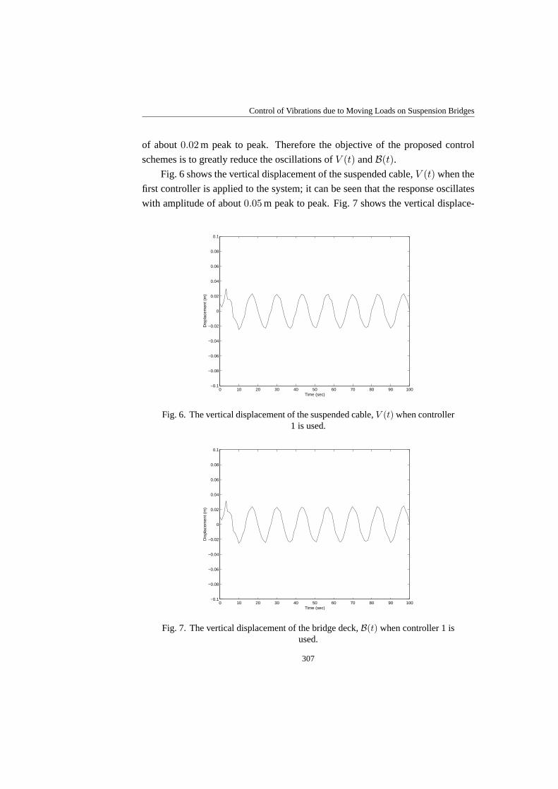
of about0.02 m peak to peak. Therefore the objective of the proposed control
schemes is to greatly reduce the oscillations ofV (t) andB(t).
Fig. 6 shows the vertical displacement of the suspended cable,V (t) when the
first controller is applied to the system; it can be seen that the response oscillates
with amplitude of about0.05 m peak to peak. Fig. 7 shows the vertical displace-
0 10 20 30 40 50 60 70 80 90 100−0.1
−0.08
−0.06
−0.04
−0.02
0
0.02
0.04
0.06
0.08
0.1
Time (sec)
Dis
plac
emen
t (m
)
Fig. 6. The vertical displacement of the suspended cable,V (t) when controller1 is used.
0 10 20 30 40 50 60 70 80 90 100−0.1
−0.08
−0.06
−0.04
−0.02
0
0.02
0.04
0.06
0.08
0.1
Time (sec)
Dis
plac
emen
t (m
)
Fig. 7. The vertical displacement of the bridge deck,B(t) when controller 1 isused.
307

M. Zribi, N. B. Almutairi, M. Abdel-Rohman
ment of the bridge deck,B(t) when the first controller is applied to the system;
it can be seen that the response oscillates with amplitude of about0.05 m peak
to peak. Fig. 8 shows the transverse displacement of the suspended cable,W (t)
when the first controller is applied to the system; it can be seen that the response
oscillates with amplitude of about0.02 m peak to peak. Hence, it can be concluded
that the first control scheme is able to greatly reduce the oscillations ofV (t) and
B(t). The controller did not have much of an effect on the transverse displacement
of the suspended cable,W (t). The plot of controller 1 versus time is shown in
Fig. 9; the range of the controller is about0.8 × 105.
0 10 20 30 40 50 60 70 80 90 100−0.1
−0.08
−0.06
−0.04
−0.02
0
0.02
0.04
0.06
0.08
0.1
Time (sec)
Dis
plac
emen
t (m
)
Fig. 8. The transverse displacement of the suspended cable,W (t) whencontroller 1 is used.
Fig. 10 shows the vertical displacement of the suspended cable,V (t) when
the second controller is applied to the system; it can be seen that the response
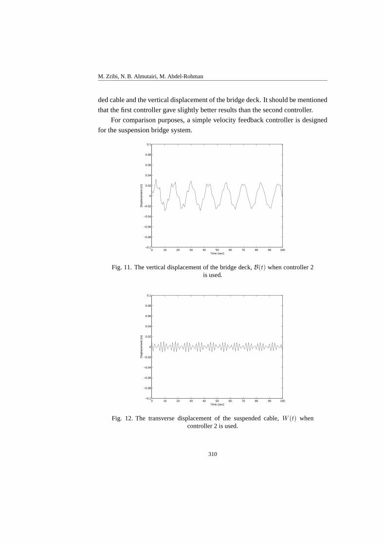
oscillates with amplitude of about0.06 m peak to peak. Fig.11 shows the vertical
displacement of the bridge deck,B(t) when the second controller is applied to the
system; it can be seen that the response oscillates with amplitude of about0.06 m
peak to peak. Fig. 12 shows the transverse displacement of the suspended cable,
W (t) when the second controller is applied to the system; it can be seen that the
response oscillates with amplitude of about0.02 m peak to peak. Hence, it can be
concluded that the second control scheme is able to greatly reduce the oscillations
of V (t) andB(t). The controller did not have much of an effect on the transverse
308

Control of Vibrations due to Moving Loads on Suspension Bridges
displacement of the suspended cable,W (t). The plot of controller 2 versus time
is shown in Fig. 13; the range of the controller is about0.9 × 105.
Therefore, the simulation results show that the proposed control schemesare
able to greatly reduce the oscillations of the vertical displacement of the suspen-
0 10 20 30 40 50 60 70 80 90 100−1
−0.8
−0.6
−0.4
−0.2
0
0.2
0.4
0.6
0.8
1x 10
5
Time (sec)
u(t)
Fig. 9. The response of controller 1 versus time.
0 10 20 30 40 50 60 70 80 90 100−0.1
−0.08
−0.06
−0.04
−0.02
0
0.02
0.04
0.06
0.08
0.1
Time (sec)
Dis
plac
emen
t (m
)
Fig. 10. The vertical displacement of the suspended cable,V (t) whencontroller 2 is used.
309
M. Zribi, N. B. Almutairi, M. Abdel-Rohman
ded cable and the vertical displacement of the bridge deck. It should be mentioned
that the first controller gave slightly better results than the second controller.
For comparison purposes, a simple velocity feedback controller is designed
for the suspension bridge system.
0 10 20 30 40 50 60 70 80 90 100−0.1
−0.08
−0.06
−0.04
−0.02
0
0.02
0.04
0.06
0.08
0.1
Time (sec)
Dis
plac
emen
t (m
)
Fig. 11. The vertical displacement of the bridge deck,B(t) when controller 2is used.
0 10 20 30 40 50 60 70 80 90 100−0.1
−0.08
−0.06
−0.04
−0.02
0
0.02
0.04
0.06
0.08
0.1
Time (sec)
Dis
plac
emen
t (m
)
Fig. 12. The transverse displacement of the suspended cable, W (t) whencontroller 2 is used.
310

Control of Vibrations due to Moving Loads on Suspension Bridges
0 10 20 30 40 50 60 70 80 90 100−1
−0.8
−0.6
−0.4
−0.2
0
0.2
0.4
0.6
0.8
1x 10
5
Time (sec)
u(t)
Fig. 13. The response of controller 2 versus time.
The controller is as follows:
u = −α1V − α2B, (35)
whereα1 andα2 are design parameters.
Fig. 14 shows the vertical displacement of the suspended cable,V (t) when
0 10 20 30 40 50 60 70 80 90 100−0.1
−0.05
0
0.05
0.1
0.15
Time (sec)
Dis
plac
emen
t (m
)
Fig. 14. The vertical displacement of the suspended cable,V (t) when thevelocity feedback controller is used.
311

M. Zribi, N. B. Almutairi, M. Abdel-Rohman
the velocity feedback controller is applied to the system; it can be seen that the
response oscillates with amplitude of about0.2 m peak to peak. Fig. 15 shows
the vertical displacement of the bridge deck,B(t) when the velocity feedback
controller is applied to the system; it can be seen that the response oscillates with
amplitude of about0.2 m peak to peak. Fig. 16 shows the transverse displacement
0 10 20 30 40 50 60 70 80 90 100−0.1
−0.05
0
0.05
0.1
0.15
Time (sec)
Dis
plac
emen
t (m
)
Fig. 15. The vertical displacement of the bridge deck,B(t) when the velocityfeedback controller is used.
0 10 20 30 40 50 60 70 80 90 100−0.1
−0.08
−0.06
−0.04
−0.02
0
0.02
0.04
0.06
0.08
0.1
Time (sec)
Dis
plac
emen
t (m
)
Fig. 16. The transverse displacement of the suspended cable, W (t) when thevelocity feedback controller is used.
312
Control of Vibrations due to Moving Loads on Suspension Bridges
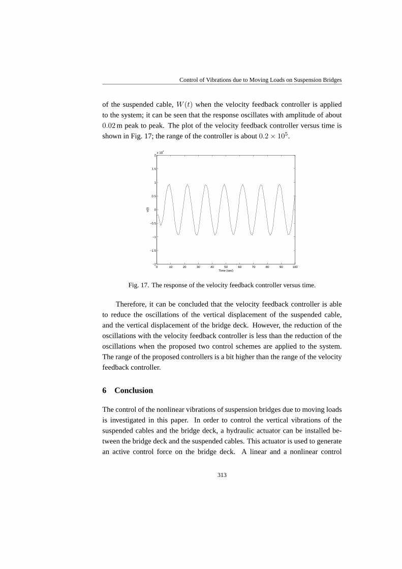
of the suspended cable,W (t) when the velocity feedback controller is applied
to the system; it can be seen that the response oscillates with amplitude of about
0.02 m peak to peak. The plot of the velocity feedback controller versus time is
shown in Fig. 17; the range of the controller is about0.2 × 105.
0 10 20 30 40 50 60 70 80 90 100−2
−1.5
−1
−0.5
0
0.5
1
1.5
2x 10
4
Time (sec)
u(t)
Fig. 17. The response of the velocity feedback controller versus time.
Therefore, it can be concluded that the velocity feedback controller is able
to reduce the oscillations of the vertical displacement of the suspended cable,
and the vertical displacement of the bridge deck. However, the reductionof the
oscillations with the velocity feedback controller is less than the reduction of the
oscillations when the proposed two control schemes are applied to the system.
The range of the proposed controllers is a bit higher than the range of thevelocity
feedback controller.
6 Conclusion
The control of the nonlinear vibrations of suspension bridges due to moving loads
is investigated in this paper. In order to control the vertical vibrations of the
suspended cables and the bridge deck, a hydraulic actuator can be installed be-
tween the bridge deck and the suspended cables. This actuator is used to generate
an active control force on the bridge deck. A linear and a nonlinear control
313
M. Zribi, N. B. Almutairi, M. Abdel-Rohman
schemes are presented to generate the active control force. These controllers
guarantee the asymptotic stability of the closed loop system. The performance
of the controlled system is investigated through simulations using the MATLAB
software. The simulation results indicate that the proposed control schemeswork
well. Moreover, simulation results indicate that the proposed controllers give
better results than a velocity feedback controller.
Appendix
The natural frequency of the cable in the vertical direction is such:
ω2
v =−H
m
L∫
0
φφ′′
dx
L∫
0
φ2dx
.
The natural frequency of the cable in the transversal direction is such:
ω2
w =−H
m
L∫
0
ψψ′′
dx
L∫
0
ψ2dx
.
The natural frequency of the bridge deck is such:
ω2
b =EI
mb
L∫
0
η η′′′′
ds
L∫
0
η2ds
.
The parametersc1, c2, c3, c4, c5, c6 andc7 are such:
c1 =1.5βEA
mL
L∫
0
φφ′2dx
L∫
0
φ2dx
, c2 =βEA
2mL
L∫
0
φψ′2dx
L∫
0
φ2dx
,
314

Control of Vibrations due to Moving Loads on Suspension Bridges
c3 =−1.5EA
m
L∫
0
φφ′2φ
′′
dx
L∫
0
φ2dx
, c4 =−EA
m
L∫
0
φφ′
ψ′
ψ′′
dx+0.5L∫
0
φφ′′
ψ′2dx
L∫
0
φ2dx
,
c5 =EA
mL
L∫
0
φψψ′′
dx
L∫
0
ψ2dx
, c6 =−EA
m
L∫
0
φ′
φ′′
ψψ′
dx+ 0.5L∫
0
φ′2ψψ
′′
dx
L∫
0
ψ2dx
,
c7 =−1.5EA
m
L∫
0
ψψ′2ψ
′′
dx
L∫
0
ψ2dx
.
The parametersd1, d2, d3 andd4 are such:
d1 =−Kc
m, d2 =
Kc
m, d3 =
Kc
mb
, d4 =−Kc
mb
.
The parametersκ1 andκ2 are such:
κ1 =2
mL, κ2 =
−2
mb L.
References
1. M. Abdel-Rohman, B. F. Spencer, Control of Wind-Induced Nonlinear scillations inSuspended Cables,Nonlinear Dynamics,37(4), pp. 341–355, 2004.
2. T. Huynh, P. Thoft-Christensen, Suspension Bridge Flutter for Girders with SeparateControl Flaps,Journal of Bridge Engineering, ASCE,6(3), pp. 168–175, 2001.
3. C. L. Lee, N. C. Perkins, Nonlinear Oscillations of Suspended Cables Containing aTwo-to-One Internal Resonance,Nonlinear Dynamics,3(6), pp. 465–490, 1992.
4. R. Shoureshi, M. Wheeler, G. Alves, D. Maguire, On implementation of activecontrol systems, in: American Control Conference, Seattle, Washington, USA,pp. 2364–2368, 1995.
5. Y. Q. Ni, B. F. Spencer, J. M. Ko, Active/Semiactive Seismic Response Control ofCable-Supported Bridges: current research status and key issues, in:EarthquakeEngineering Frontiers in the New Millennium,B. F. Spencer, Jr., Y. X. Hu (Eds.),A. A. Balkema, Rotterdam, Netherlands, 2001.
315
M. Zribi, N. B. Almutairi, M. Abdel-Rohman
6. P. Thoft-Christensen, Active Control of Suspension Bridges, in: Second EuropeanConference on Structural Control, Champs sur Marne, France, 2000.
7. P. Thoft-Christensen, Improving the Dynamics of Suspension Bridges using ActiveControl Systems, in:The 2nd International Workshop on Life-cycle Cost Analysisand Design of Civil Infrastructure Systems, Ube, Yamaguchi, Japan,pp. 293–304,2001.
8. K. Wilde, Y. Fujino, Aerodynamic Control of Bridge Deck Flutter by ActiveSurfaces,Journal of Engineering Mechanics, ASCE,124(7), pp. 718–727, 1998.
9. S. Phongkumising, K. Wilde, Y. Fujino, Analytical study on flutter suppression byeccentric mass method on FEM model of long-span suspension bridge, Journal ofWind Engineering and Industrial Aerodynamics,89(6), pp. 515–534, 2001.
10. H. Kobayashi, H. Nagaoka, Active Control of Flutter of a Suspension Bridge,Journalof Wind Engineering and Industrial Aerodynamics,41(1–3), pp. 143–151, 1992.
11. T. Miyata, H. Yamada, N. N. Dung, K. Kazama, On Active Control and StructuralResponse Control of the Coupled Flutter Problem for Long Span Bridges, in:Proceedings of the 1st World Conference on Structural Control, pp. 40–49, 1994.
12. S. Preidikman, D. T. Mook, A New Method for Actively Suppressing Flutter ofSuspension Bridges,Journal of Wind Engineering and Industrial Aerodynamics,69,pp. 955–974, 1997.
13. C. S. Cai, S. R. Chen, Wind vibration mitigation of long-span bridges in hurricanes,Journal of Sound and Vibration,274(1–2), pp. 421–432, 2004.
14. M. Abdel-Rohman, Design of a Simple Controller to Control Suspension BridgeNon-linear Vibrations due to Moving Loads,Journal of Vibration and Control,11(7),pp. 867–885, 2005.
15. M. Abdel-Rohman, J. Al-Duaij, Dynamic Response of Hinged-Hinged SingleSpan Bridges with Uneven Deck,Journal of Computers and Structures,59(2),pp. 291–299, 1996.
16. M. Abdel-Rohman, H. Askar, Control by Passive TMD of Wind-Induced NonlinearVibrations in Cable Stayed Bridges,Journal of Vibration and Control,2(2),pp. 251–267, 1996.
17. Y. Chen, C. A. Tan, L. A. Bergman, T.-C. Tsao, Smart Suspension Systems forBridge-Friendly Vehicles, in:The 9th SPIE Annual International Symposium onSmart Structures and Materials, San Diego, California, USA, 2002.
18. R. Karoumi Dynamic Response of Cable-Stayed Bridges Subjected to MovingVehicles, in:IABSE 15th Congress, Denmark,pp. 87–92, 1996.
316
Control of Vibrations due to Moving Loads on Suspension Bridges
19. R. Karoumi, Modeling of Cable Stayed Bridges for Analysis of Traffic InducedVibrations, in:IMAC-XVIII Conference on Structural Dynamics, San Antonio, Texas,USA,2000.
20. T.-C. Tsao, C.-A. Tan, A. Pesterev, B. Yang, L. A. Bergman, Control orientedformulation for structures interacting with moving loads,in: American ControlConference,pp. 441–446, 2001.
21. W.-X. Ren, G. E. Blandford, I. E. Harik, Roebling Suspension Bridge, I: Finite-Element Model and Free Vibration Response,Journal of Bridge Engineering, ASCE,9(2), pp. 110–118, 2004.
22. W.-X. Ren, I. E., Harik, G. E. Blandford, M. Lenett, T. M. Baseheart, RoeblingSuspension Bridge, II: Ambient Testing and Live-Load Response,Journal of BridgeEngineering, ASCE,9(2), pp. 119–126, 2004.
23. S. J. Dyke, G. Turan, J. M., Caicedo, L. A. Bergman, Summary of the BenchmarkControl Problem for Seismic Response of Cable-Stayed Bridges, in: The SecondEuropean Conference on Structural Control, Paris, France,2000.
24. S. J. Dyke, J. M. Caicedo, G. Turan, L. A., Bergman, S. Hague, Phase I BenchmarkControl Problem for Seismic Response of Cable-Stayed Bridges, Journal ofStructural Engineering: Special Issue on Semi-active Control, 129(7), 2003.
25. H. J. Jung, B. F. Spencer, J., I.-W. Lee, Benchmark Control Problem of a SeismicallyExcited Cable Stayed Bridges Using Magnetorheological (MR) Dampers, in:The3rd World Conference in Structural Control, Como, Italy,2002.
26. S. J. Moon, L. A., Bergman P. Voulgaris, Sliding Mode Control of a Semi-ActivelyControlled Cable-Stayed Bridge, in:The 3rd World Conference in Structural Control,Como, Italy,2002.
27. F. Paulet-Crainiceanu, L. Bakule, J. Rodellar, J. M. Rosell, DecentralizedOverlapping Control Design for the Cable-Stayed BenchmarkModel, in: The 3rdWorld Conference in Structural Control, Como, Italy,2002.
28. G. Turan, P. Voulgaris, L. Bergman,µ-Syntesis Control of a Cable-Stayed BridgeAgainst Earthquake Excitation, in:The 3rd World Conference in Structural Control,Como, Italy,2002.
29. J. M. Caicedo, S. J. Dyke, S. J. Moon, L. A. Bergman, G. Turan, S. Hague, Phase IIBenchmark Control Problem for Seismic Response of Cable-Stayed Bridges,Journalof Structural Control: Special Issue on the Cable-Stayed Bridge Seismic BenchmarkControl Problem,10(3–4), pp. 137–168, 2003.
317
M. Zribi, N. B. Almutairi, M. Abdel-Rohman
30. S.-J. Moon, S. J. Dyke, J. M. Caicedo, L. A. Bergman, S. Hague, Phase II BenchmarkControl Problem for Cable-Stayed Bridges, in:The 3rd World Conference inStructural Control, Como, Italy,2002.
31. F. Bontempi, F. Casciati, M. Giudici, Seismic response of a cable-stayed bridge:active and passive control systems (Benchmark Problem),Journal of StructuralControl: Special Issue on the Cable-Stayed Bridge Seismic Benchmark ControlProblem,10(3–4), pp. 169–185, 2003.
32. H. Iemura, M. H. Pradono, Application of pseudo-negative stiffness control to thebenchmark cable-stayed bridge,Journal of Structural Control: Special Issue on theCable-Stayed Bridge Seismic Benchmark Control Problem,10(3–4), pp. 187–203,2003.
33. K.-S. Park, H.-J. Jung, Jr., I.-W. Lee, Hybrid control systems for seismic protectionof a phase II benchmark cable-stayed bridge,Journal of Structural Control: SpecialIssue on the Cable-Stayed Bridge Seismic Benchmark ControlProblem,10(3–4),pp. 231–247, 2003.
34. J. N., Yang, S. Lin, F. Jabbari, H2-based control strategies for civil engineeringstructures,Journal of Structural Control: Special Issue on the Cable-Stayed BridgeSeismic Benchmark Control Problem,10(3–4), pp. 205–230, 2003.
35. M. Irvine,Cable Structures,Dover Publications, Inc., New York, 1992.
36. A. Luongo, G. Piccardo, Nonlinear Galloping of Sagged Cables in 1:2 InternalResonance,Journal of Sound and Vibration,214(5), pp. 915–940, 1998.
37. G. V. Rao, R. N. Iyengar, Internal Resonance and Nonlinear Response of a Cableunder Periodic Excitation,Journal of Sound and Vibration,149(1), pp. 25–41, 1991.
318