Line distance protection REL670 Version 2.2 Product guide...2. Application. M13636-3 v14. The...
167
Relion ® 670 SERIES Line distance protection REL670 Version 2.2 Product guide
Transcript of Line distance protection REL670 Version 2.2 Product guide...2. Application. M13636-3 v14. The...

Relion® 670 SERIES
Line distance protection REL670Version 2.2Product guide

Contents
1. Document revision history.................................................3
2. Application.............................................................................4
3. Available functions............................................................. 12
4. Differential protection......................................................29
5. Impedance protection......................................................30
6. Wide area measurement system................................... 35
7. Current protection.............................................................36
8. Voltage protection.............................................................38
9. Frequency protection....................................................... 39
10. Multipurpose protection................................................ 39
11. General calculation...........................................................39
12. Secondary system supervision.....................................40
13. Control................................................................................. 41
14. Scheme communication.................................................43
15. Logic.................................................................................... 45
16. Monitoring..........................................................................47
17. Metering............................................................................. 50
18. Human machine interface.............................................. 51
19. Basic IED functions...........................................................51
20. Ethernet...............................................................................52
21. Station communication ................................................. 52
22. Remote communication................................................. 54
23. Hardware description..................................................... 55
24. Connection diagrams......................................................58
25. Technical data................................................................... 59
26. Ordering for customized IED.......................................142
27. Ordering for pre-configured IED................................ 154
28. Ordering for Accessories.............................................. 161
Disclaimer
The information in this document is subject to change without notice and should not be construed as a commitment by ABB. ABB assumes no
responsibility for any errors that may appear in this document. Drawings and diagrams are not binding.
© Copyright 2017 ABB. All rights reserved.
Trademarks
ABB and Relion are registered trademarks of the ABB Group. All other brand or product names mentioned in this document may be trademarks or
registered trademarks of their respective holders.
Line distance protection REL670 1MRK 506 372-BEN HVersion 2.2
2 ABB

1. Document revision historyGUID-34B323E4-1319-4D42-80CE-29B0F2D36E2C v2
Table 1. Document revision history
Documentrevision
Date Product revision History
- 2017-07 2.2.0 First release for product version 2.2
A 2017-10 2.2.1 Ethernet ports with RJ45 connector added. enhancements/updatesmade to ZMFPDIS and ZMFCPDIS.
B 2018-04 2.2.1 Document enhancements and corrections
C Document not released
D 2018-07 2.2.2 LDCM galvanic X.21 added. Function PTRSTHR added. Ordering sectionupdated.
E 2018-11 2.2.2 Technical data updated for PSM and EF4PTOC. Corrections/enhancements made to OC4PTOC, TRPTTR, UV2PTUV and OV2PTOV. Case dimensions updated.
F Document not released
G 2018-12 2.2.3 Functions CHMMHAI, VHMMHAI, DELVSPVC, DELSPVC and DELISPVCadded. Updates/enhancements made to ZMFPDIS, ZMFCPDIS, CCRBRF,REALCOMP, PTRSTHR and FNKEYMDx. Ordering section updated.
H 2019-05 2.2.3 PTP enhancements and corrections
Line distance protection REL670Version 2.2
1MRK 506 372-BEN H Issued: May 2019
Revision: H
ABB 3© Copyright 2017 ABB. All rights reserved

2. ApplicationM13636-3 v14
The Intelligent Electronic Device (IED) is used for theprotection, control and monitoring of overhead linesand cables in solidly, impedance earthed or isolatednetworks. The IED can be used up to the high voltagelevels. It is suitable for the protection of heavily loadedlines and multi-terminal lines where the requirement fortripping is one-, two- and/or three-phase. The IED isalso suitable as backup protection of powertransformers, reactors and so on.
With high functional integration capability, theprotection of two overhead lines, one as the main andanother as the backup, can be achieved using a singleIED. When deployed in such applications, this can lead tooverall cost savings including reduced engineering.
Distance protection with quadrilateral or mhocharacteristics is available. The full scheme distanceprotection provides protection of power lines with highsensitivity and low requirement on remote endcommunication. The six zones have fully independentmeasuring and setting which gives high flexibility for alltypes of lines. Load encroachment and adaptive reachcompensation are included.
The modern technical solution offers fast operatingtime of typically less than one cycle.
The IED also includes an alternative for use onimpedance earthed or isolated networks. It includesphase preference logic to select and trip only one line atcross-country faults.
The autorecloser for single-, two-, and/or three-phasetripping and autoreclosing includes priority features formulti-breaker arrangements. It co-operates with thesynchrocheck function with high-speed or delayedreclosing.
A high impedance differential protection can be used toprotect T-feeders or line reactors.
High set instantaneous phase and earth overcurrent,four step directional or non-directional delayed phaseand earth overcurrent, sensitive earth fault for notdirect earthed systems, thermal overload and two stepunder and overvoltage protection are examples of theavailable functions allowing the user to fulfill anyapplication requirement.
The distance phase and earth fault protection, and thedirectional earth overcurrent protection cancommunicate with remote end in any teleprotectioncommunication scheme. With the included remotecommunication, following the IEEE C37.94 standard, upto 192 channels for intertrip and binary signals are
available per LDCM communication module in thecommunication between the IEDs.
The IED can also be provided with full bay control andinterlocking functionality including co-operation withthe synchrocheck function to allow integration of themain or backup control.
Out of Step function is available to separate powersystem sections close to electrical centre at occurringout of step.
The IED can be used in applications with IEC/UCA61850-9-2LE process bus with up to eight merging units(MU) depending on other functionality included in theIED. Each MU has eight analogue channels, normally fourcurrents and four voltages. Conventional and MergingUnit channels can be mixed freely in the application.
Logic is prepared with a graphical tool. The advancedlogic capability allows special applications such asautomatic opening of disconnectors in multi-breakerarrangements, closing of breaker rings, load transferlogics and so on. The graphical configuration tool withdelay mode, ensures simple and fast testing andcommissioning.
Disturbance recorder and fault locator are available toallow independent post-fault analysis after primarydisturbances.
Forcing of binary inputs and outputs is a convenient wayto test wiring in substations as well as testingconfiguration logic in the IEDs. Basically it means that allbinary inputs and outputs on the IED I/O modules (BOM,BIM, IOM & SOM) can be forced to arbitrary values.
Central Account Management is an authenticationinfrastructure that offers a secure solution for enforcingaccess control to IEDs and other systems within asubstation. This incorporates management of useraccounts, roles and certificates and the distribution ofsuch, a procedure completely transparent to the user.
Flexible Product Naming allows the customer to use anIED-vendor independent IEC 61850 model of the IED.This customer model will be used as the IEC 61850 datamodel, but all other aspects of the IED will remainunchanged (e.g., names on the local HMI and names inthe tools). This offers significant flexibility to adapt theIED to the customers' system and standard solution.
M11788-3 v10
Communication via optical connections ensuresimmunity against disturbances.
SEMOD51220-5 v14
Four packages have been defined for the followingapplications:
Line distance protection REL670 1MRK 506 372-BEN HVersion 2.2
4 ABB© Copyright 2017 ABB. All rights reserved

• Single breaker, 1/3 phase tripping, isolated or highimpedance earthed systems (A41)
• Single breaker, 1/3 phase tripping (A42)• Multi breaker, 1/3 phase tripping (B42)• Single breaker, 1/3 phase tripping, with PMU (D42)
Optional functions are not configured but a maximumconfiguration with all optional functions are available as
template in the application configuration tool. Analoginputs and binary input/output signals are pre-definedfor basic use. Other signals may be required by eachparticular application.
Add binary I/O boards as required for the applicationwhen ordering.
Line distance protection REL670 1MRK 506 372-BEN HVersion 2.2
ABB 5© Copyright 2017 ABB. All rights reserved

Description of configuration A41GUID-E5AFA7F9-AA08-48B1-9ABA-B6A9A0B9BE1E v1
QB1 QB2
QA1
QB9
QC9
WA1
WA2REL670 A41 – Single breaker with three phase tripping for
high ohmic and resonance earthed systems 12AI (6I+6U)
ZCLC PSCH
67N
SDE PSDE
IN>
OC4 PTOC
51_67 4(3I>)
LC PTTR
26 θ>
CC RBRF
50BF 3I>BF
Other Functions available from the function library
ROV2 PTOV
59N 2(U0>)
EF4 PTOC
51N_67N 4(IN>)
EF PIOC
50N IN>>
VN MMXU
MET UN
VN MMXU
MET UN
Optional Functions
S SIMG
63
ZC PSCH
85
Q CBAY
3 Control
WA2_VT
WA1_VT
LINE_CT
LINE_VT
SMP PTRC
94 1->0
SMB RREC
79 5(0→1)
SMP PTRC
94 1→0
SES RSYN
25 SC/VC
ZCV PSOF
LOV PTUV
27 3U<
V MSQI
MET Usqi
VN MMXU
MET UN
DRP RDRE
DFR/SER DR
V MMXU
MET U
LMB RFLO
21FL FL
ZMF PDIS
21 Z<
FUF SPVC
U>/I<
C MMXU
MET I
C MSQI
MET Isqi
CV MMXN
MET P/Q
S CILO
3 Control
S CSWI
3 Control
VD SPVC
60 Ud>
CV GAPC
2(I>/U<)
Q CRSV
3 Control
S XSWI
3 Control
UV2 PTUV
27 2(3U<)
OV2 PTOV
59 2(3U>)
CC PDSC
52PD PD
BRC PTOC
46 Iub>
PH PIOC
50 3I>>
S SCBR
Control
S SCBR
Control
S SCBR
Control
SA PTUF
81 f<
SA PTOF
81 f>
SA PFRC
81 df/dt<>
NS4 PTOC
46I2 4(I2>)
PSL PSCH
Zpsl
PMU REP
VR PVOC
51V 2(I>/U<)
ZM RPSB
68 Zpsb
STB PTOC
50STB 3I>STB
LF PTTR
26 θ>
S SIML
71
ZCRW PSCH
85
PPL2 PHIZ
S XCBR
3 Control
IEC16000195-2-en.vsd
VHM MHAI
VTHD UTHD
PTR STHR
51TF
CHM MHAI
ITHDITHD
77V_78V DELTAU
DELV SPVC
71 DELTAI
DELI SPVC DEL SPVC
DELTA
ETP MMTR
MET W/Varh
IEC16000195 V2 EN-US
Figure 1. Configuration diagram for configuration A41
Line distance protection REL670 1MRK 506 372-BEN HVersion 2.2
6 ABB© Copyright 2017 ABB. All rights reserved

Description of configuration A42GUID-8BA33493-DB51-4FCC-A9C6-39E6F78A2606 v1
QB1 QB2
QA1
QB9
QC9
WA1
WA2REL670 A42 – Single breaker with single or three phase tripping
12AI (6I+6U)
CC RBRF
50BF 3I>BF
26
LC PTTR
θ>
OC4 PTOC
51_67 4(3I>)
VN MMXU
MET UN
VN MMXU
MET UN
WA2_VT
WA1_VT
LINE_CT
LINE_VT
SMP PTRC
94 1->0
SMB RREC
79 5(0→1)
SMP PTRC
94 1→0
SES RSYN
25 SC/VC
UV2 PTUV
27 2(3U<)
V MSQI
MET Usqi
VN MMXU
MET UN
V MMXU
MET U
LMB RFLO
21FL FL
EC PSCH
85
ZCRW PSCH
85
ZC PSCH
85
ZM RPSB
68 Zpsb
ZMF PDIS
21 Z<
ZCV PSOF FUF SPVC
U>/I<
DRP RDRE
DFR/SER DR
OV2 PTOV
59 2(3U>)
ECRW PSCH
85
LOV PTUV
27 3U<
C MMXU
MET I
C MSQI
MET Isqi
ETP MMTR
MET W/Varh
CV MMXN
MET P/Q
CC PDSC
52PD PD
EF PIOC
50N IN>>
PH PIOC
50 3I>>
BRC PTOC
46 Iub>
S SCBR
Control
S SCBR
Control
S SCBR
Control
Other Functions available from the function library
S CILO
3 Control
S CSWI
3 Control
ROV2 PTOV
59N 2(U0>)
CCS SPVC
87 INd/I
VDC PTOV
60 Ud>
NS4 PTOC
46I2 4(I2>)
HZ PDIF
87 Id>
CV GAPC
2(I>/U<)
Optional Functions
ZCLC PSCH
Q CBAY
3 Control
Q CRSV
3 Control
S XSWI
3 Control
SDE PSDE
67N IN>
GUP PDUP
37 P<
PSL PSCH
Zpsl
VD SPVC
60 Ud>
OEX PVPH
24 U/f>
GOP PDOP
32 P>
SA PFRC
81 df/dt<>
SA PTOF
81 f>
SA PTUF
81 f>
PSP PPAM
78 Ucos
OOS PPAM
78 Ucos
ZC1P PSCH
85
ZC1W PSCH
85
STB PTOC
50STB 3I>STB
VR PVOC
51V 2(I>/U<)
LF PTTR
26 θ>
PMU REP
S SIMG
63
S SIML
71 S SCBR
Control
S SCBR
Control
S XCBR
3 Control
EF4 PTOC
51N_67N 4(IN>)
IEC16000196-2-en.vsd
7V_78V DELTAU
DELV SPVC DEL SPVC
7 DELTA71 DELTAI
DELI SPVC
VHM MHAI
VTHD UTHD
PTR STHR
51TF
CHM MHAI
ITHDITHD
IEC16000196 V2 EN-US
Figure 2. Configuration diagram for configuration A42
Line distance protection REL670 1MRK 506 372-BEN HVersion 2.2
ABB 7© Copyright 2017 ABB. All rights reserved
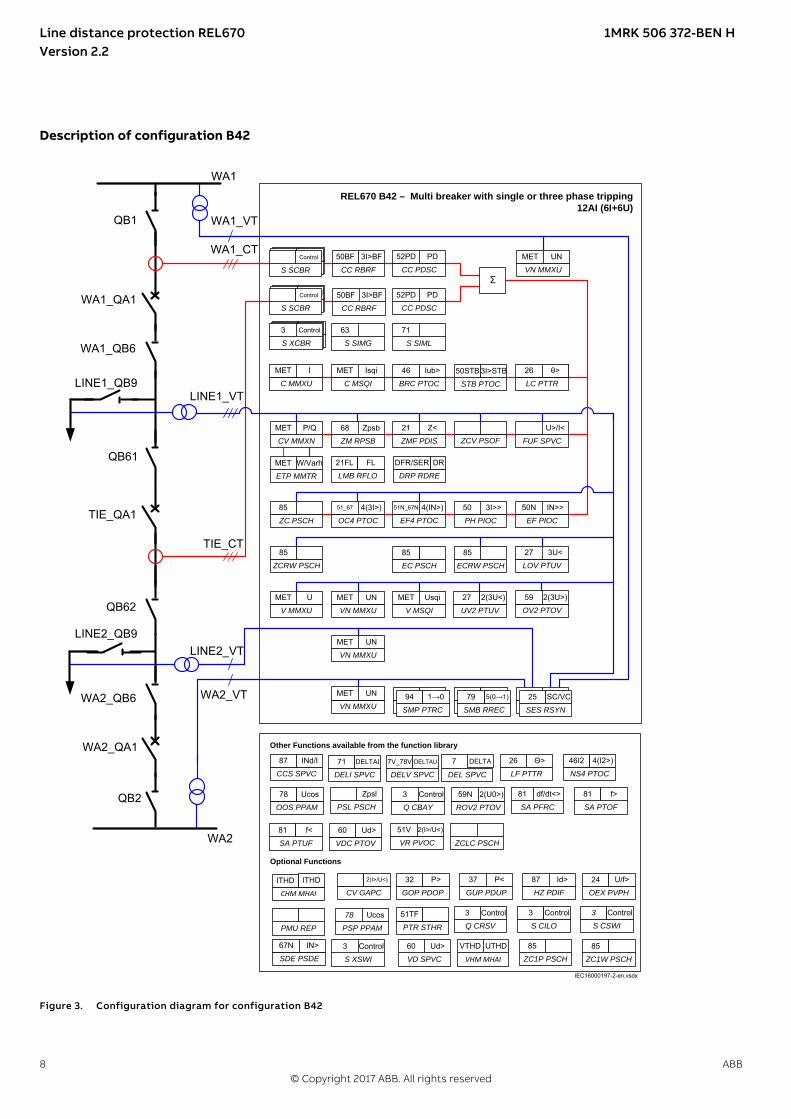
Description of configuration B42GUID-1F828D7F-B53B-418D-8A14-A11D3224B8C8 v1
QB1
WA1_QB6
LINE1_QB9
QB61
QB62
LINE2_QB9
WA2_QB6
WA1_QA1
TIE_QA1
REL670 B42 – Multi breaker with single or three phase tripping 12AI (6I+6U)
VN MMXU
MET UN
LMB RFLO
21FL FL
ETP MMTR
MET W/Varh
QB2
WA2_QA1
ZMF PDIS
21 Z<
V MSQI
MET Usqi
STB PTOC
50STB 3I>STB
C MSQI
MET Isqi
BRC PTOC
46 Iub>
LC PTTR
26 3I>STBθ>
EF PIOC
50N IN>>
Other Functions available from the function library
SA PTUF
81 f<
GUP PDUP
37 P<
NS4 PTOC
46I2 4(I2>)
CV GAPC
2(I>/U<)
VD SPVC
60 Ud>
SA PTOF
81 f>
Optional Functions
ROV2 PTOV
59N 2(U0>)
VDC PTOV
60 Ud>
PSP PPAM
78 Ucos
GOP PDOP
32 P>
ZM RPSB
68 Zpsb
UV2 PTUV
27 2(3U<)
V MMXU
MET U
CV MMXN
MET P/Q
CCS SPVC
87 INd/I
OEX PVPH
24 U/f>
ZCLC PSCH
SDE PSDE
67N IN>
HZ PDIF
87 Id>
SA PFRC
81 df/dt<>
PSL PSCH
Zpsl
ZC PSCH
85
SMB RREC
79 0→1
SMP PTRC
94 1→0
SES RSYN
25 SC
FUF SPVC
U>/I<
ΣCC PDSC
52PD PD
S CILO
3 Control
Q CBAY
3 Control
S CSWI
3 Control
Q CRSV
3 Control
S XSWI
3 Control
CC RBRF
50BF 3I>BF
CC RBRF
50BF 3I>BF
ZCV PSOF
PH PIOC
50 3I>>
EF4 PTOC
51N_67N 4(IN>)
OC4 PTOC
51_67 4(3I>)
C MMXU
MET I
OV2 PTOV
59 2(3U>)
EC PSCH
85
LOV PTUV
27 3U<
ECRW PSCH
85
VN MMXU
MET UN
VN MMXU
MET UN
VN MMXU
MET UN
WA1
WA1_VT
WA1_CT
TIE_CT
LINE1_VT
WA2
WA2_VT
LINE2_VT
ZCRW PSCH
85
DRP RDRE
DFR/SER DR
CC PDSC
52PD PD
ZC1P PSCH
85
ZC1W PSCH
85
SMP PTRC
94 1→0
SES RSYN
25 SC/VC
SMB RREC
5(0→1)79
S SCBR
Control
S SCBR
Control
S SCBR
Control
S SCBR
Control
S SCBR
Control
S SCBR
Control
OOS PPAM
78 Ucos
LF PTTR
26 Θ>
PMU REP
VR PVOC
51V 2(I>/U<)
S SIMG
63
S SIML
71 S SCBR
Control
S SCBR
Control
S XCBR
3 Control
IEC16000197-2-en.vsdx
77V_78V DELTAU
DELV SPVC
71 DELTAI
DELI SPVC DEL SPVC
DELTA
VHM MHAI
VTHD UTHD
PTR STHR
51TF
CHM MHAI
ITHDITHD
IEC16000197 V2 EN-US
Figure 3. Configuration diagram for configuration B42
Line distance protection REL670 1MRK 506 372-BEN HVersion 2.2
8 ABB© Copyright 2017 ABB. All rights reserved

Description of configuration D42GUID-C0623D78-EE13-44E9-BE02-951B54878879 v1
QB1 QB2
QA1
QB9
QC9
WA1
WA2REL670 D42 – Single breaker with single or three phase tripping with PMU functionality
CC RBRF
50BF 3I>BF
26
LC PTTR
θ>
OC4 PTOC
51_67 4(3I>)
Other Functions available from the function library
S CILO
3 Control
S CSWI
3 Control
ROV2 PTOV
59N 2(U0>)
CCS SPVC
87 INd/I
VDC PTOV
60 Ud>
NS4 PTOC
46I2 4(I2>)
HZ PDIF
87 Id>
VN MMXU
MET UN
VN MMXU
MET UN
Optional Functions
ZCLC PSCH
Q CBAY
3 Control
Q CRSV
3 Control
S XSWI
3 Control
WA2_VT
WA1_VT
LINE_CT
LINE_VT
SMP PTRC
94 1->0
SMB RREC
79 5(0→1)
SMP PTRC
94 1→0
SES RSYN
25 SC/VC
UV2 PTUV
27 2(3U<)
V MSQI
MET Usqi
VN MMXU
MET UN
V MMXU
MET U
LMB RFLO
21FL FL
EC PSCH
85
ZCRW PSCH
85
ZC PSCH
85
ZM RPSB
68 Zpsb
ZMF PDIS
21 Z<
ZCV PSOF FUF SPVC
U>/I<
SDE PSDE
67N IN>
GUP PDUP
37 P<
PSL PSCH
Zpsl
VD SPVC
60 Ud>
OEX PVPH
24 U/f>
GOP PDOP
32 P>
SA PFRC
81 df/dt<>
SA PTOF
81 f>
SA PTUF
81 f>
PSP PPAM
78 Ucos
OOS PPAM
78 Ucos
DRP RDRE
DFR/SER DR
OV2 PTOV
59 2(3U>)
ECRW PSCH
85
LOV PTUV
27 3U<
C MMXU
MET I
C MSQI
MET Isqi
ETP MMTR
MET W/Varh
CV MMXN
MET P/Q
ZC1P PSCH
85
ZC1W PSCH
85
CC PDSC
52PD PD
EF PIOC
50N IN>>
PH PIOC
50 3I>>
BRC PTOC
46 Iub>
S SCBR
Control
S SCBR
Control
S SCBR
Control
STB PTOC
50STB 3I>STB
IEC16000198-2-en.vsdx
IEEE Std 1344
IEEE Std C37.118
Phasor data`
PMU REP
VR PVOC
51V 2(I>/U<)
LF PTTR
26 θ>
S SIMG
63
S SIML
71 S SCBR
Control
S SCBR
Control
S XCBR
3 Control
12AI (6I+6U)
EF4 PTOC
51N_67N 4(IN>)
DELI SPVC
71 DELTAI
DEL SPVC
7 DELTA
DELV SPVC
7V_78V DELTAU
VHM MHAI
VTHD UTHD
PTR STHR
51TF
CV GAPC
2(I>/U<)
CHM MHAI
ITHD ITHD
IEC16000198 V2 EN-US
Figure 4. Configuration diagram for configuration D42
Line distance protection REL670 1MRK 506 372-BEN HVersion 2.2
ABB 9© Copyright 2017 ABB. All rights reserved

SEMOD51303-4 v7
Z <55
SC/VCO->I
3I>44
IN>44
I->O
CLOSE
TRIP
BUS A
BUS B
21
51/67
51N/67N
79 25
94/86
3I>50BF
TRIP BUSBAR
en05000276.vsd
3U>59
3U<27
2
22
2
IEC05000276-1 V1 EN-US
Figure 5. The single breaker packages for single- and three phase tripping typical arrangement for one protection sub-system is shownhere.
Line distance protection REL670 1MRK 506 372-BEN HVersion 2.2
10 ABB© Copyright 2017 ABB. All rights reserved

Z <55
SC/VCO->I
3I>44
IN>44
3U>22
3U<22
I->O
CLOSE
TRIP
BUS A
21
51/67
51N/67N
59
27
79 25
94/86
3I>50BF
TRIP BUSBAR & CB2
3I>50BF
S
SC/VCO->I
I->O CLO
SE
TRIP
25
94/86
79
IEC05000317-2-en.vsd
TRIP
CB1/3
CB1
CB2
IEC05000317 V2 EN-US
Figure 6. The multi breaker packages for single- and three phase tripping typical arrangement for one protection sub-system is shownhere. Auto-reclose, Synchrocheck and Breaker failure functions are included for each of the two breakers.
GUID-79B8BC84-4AAB-44E7-86CD-FF63098B009D v3
The basic delivery includes one binary input module andone binary output module, which is sufficient for thedefault configured I/O to trip and close circuit breaker.All IEDs can be reconfigured with the help of theapplication configuration tool in PCM600. The IED canbe adapted to special applications and special logic canbe developed, such as logic for automatic opening ofdisconnectors and closing of ring bays, automatic loadtransfer from one busbar to the other, and so on.
The basic IED configuration is provided with the signalmatrix, single line diagram and the applicationconfiguration prepared for the functions included in theproduct by default. All parameters should be verified by
the customer, since these are specific to the system,object or application. Optional functions and optionalI/O ordered will not be configured at delivery. It shouldbe noted that the standard only includes one binaryinput and one binary output module and only the keyfunctions such as tripping are connected to the outputsin the signal matrix tool. The required total I/O must becalculated and specified at ordering.
The configurations are as far as found necessaryprovided with application comments to explain why thesignals have been connected in the special way. Onrequest, ABB is available to support the re-configurationwork, either directly or to do the design checking.
Line distance protection REL670 1MRK 506 372-BEN HVersion 2.2
ABB 11© Copyright 2017 ABB. All rights reserved

3. Available functionsGUID-F5776DD1-BD04-4872-BB89-A0412B4B5CC3 v1
The following tables list all thefunctions available in the IED. Thosefunctions that are not exposed to theuser or do not need to be configuredare not described in this manual.
Main protection functionsGUID-66BAAD98-851D-4AAC-B386-B38B57718BD2 v15
Table 2. Example of quantities
2 = number of basic instances
0-3 = option quantities
3-A03 = optional function included in packages A03 (refer to ordering details)
Line distance protection REL670 1MRK 506 372-BEN HVersion 2.2
12 ABB© Copyright 2017 ABB. All rights reserved

IEC 61850 orfunction name
ANSI Function description Line Distance
REL670(Customized)
REL
670
(A41
)
REL
670
(A42
)
REL
670
(B42
)
REL
670
(D42
)
Differential protection
HZPDIF 87 High impedance differential protection, singlephase
00-03 3-A02 3-A02 3-A02
LDRGFC 11REL Additional security logic for differentialprotection
0-1
Impedance protection
ZMQPDIS,ZMQAPDIS
21 Distance protection zone, quadrilateralcharacteristic
0-5
ZDRDIR 21D Directional impedance quadrilateral 0-2
ZMCPDIS,ZMCAPDIS
21 Distance measuring zone, quadrilateralcharacteristic for series compensated lines
0-6
ZDSRDIR 21D Directional impedance quadrilateral, includingseries compensation
0-2
FDPSPDIS 21 Phase selection, quadrilateral characteristic withfixed angle
0-2
ZMHPDIS 21 Full-scheme distance protection, mhocharacteristic
0-5
ZMMPDIS,ZMMAPDIS
21 Full-scheme distance protection, quadrilateralfor earth faults
0-5
ZDMRDIR 21D Directional impedance element for mhocharacteristic
0-2
ZDARDIR Additional distance protection directionalfunction for earth faults
0-2
ZSMGAPC Mho impedance supervision logic 0-1
FMPSPDIS 21 Faulty phase identification with loadenchroachment
0-2
ZMRPDIS,ZMRAPDIS
21 Distance measuring zone, quad characteristicseparate Ph-Ph and Ph-E settings
0-5
FRPSPDIS 21 Phase selection, quadrilateral characteristic withsettable angle
0-2
ZMFPDIS 21 High speed distance protection, quad and mhocharacteristic
0-2 1 1 1 1
ZMFCPDIS 21 High speed distance protection for series comp.lines, quad and mho characteristic
0-2
PPLPHIZ Phase preference logic 0-1
PPL2PHIZ Phase preference logic 0-1 1
ZMRPSB 68 Power swing detection 0-1 1 1 1 1
PSLPSCH Power swing logic 0-1 1 1 1 1
Line distance protection REL670 1MRK 506 372-BEN HVersion 2.2
ABB 13© Copyright 2017 ABB. All rights reserved

IEC 61850 orfunction name
ANSI Function description Line Distance
REL670(Customized)
REL
670
(A41
)
REL
670
(A42
)
REL
670
(B42
)
REL
670
(D42
)
PSPPPAM 78 Poleslip/out-of-step protection 0-2 1-B24 1-B24 1-B24
OOSPPAM 78 Out-of-step protection 0-1 1 1 1
ZCVPSOF Automatic switch onto fault logic, voltage andcurrent based
1 1 1 1 1
Line distance protection REL670 1MRK 506 372-BEN HVersion 2.2
14 ABB© Copyright 2017 ABB. All rights reserved

Back-up protection functionsGUID-A8D0852F-807F-4442-8730-E44808E194F0 v15
IEC 61850 orfunction name
ANSI Function description Line Distance
REL670(Customized)
REL
670
(A41
)
REL
670
(A42
)
REL
670
(B42
)
REL
670
(D42
)
Current protection
PHPIOC 50 Instantaneous phase overcurrent protection 0-3 1 1 1 1
OC4PTOC 51_671) Directional phase overcurrent protection, foursteps
0-3 1 1 1 1
EFPIOC 50N Instantaneous residual overcurrent protection 0-3 1 1 1 1
EF4PTOC 51N67N2)
Directional residual overcurrent protection,four steps
0-3 1 1 1 1
NS4PTOC 46I2 Four step directional negative phase sequenceovercurrent protection
0-2 1 1 1 1
SDEPSDE 67N Sensitive directional residual overcurrent andpower protection
0-1 1 1-C16 1-C16 1-C16
LCPTTR 26 Thermal overload protection, one timeconstant, Celsius
0-2 1 1 1 1
LFPTTR 26 Thermal overload protection, one timeconstant, Fahrenheit
0-2 1 1 1 1
CCRBRF 50BF Breaker failure protection 0-2 1 1 2 1
STBPTOC 50STB Stub protection 0-2 1 1 1B1-B27
1
CCPDSC 52PD Pole discordance protection 0-2 1 1 2 1
GUPPDUP 37 Directional underpower protection 0-2 1-C39 1-C39 1-C39
GOPPDOP 32 Directional overpower protection 0-2 1-C39 1-C39 1-C39
BRCPTOC 46 Broken conductor check 1 1 1 1 1
VRPVOC 51V Voltage restrained overcurrent protection 0-3 1 1 1 1
Voltage protection
UV2PTUV 27 Two step undervoltage protection 0-2 1 1 1 1
OV2PTOV 59 Two step overvoltage protection 0-2 1 1 1 1
ROV2PTOV 59N Two step residual overvoltage protection 0-2 1 1 1 1
OEXPVPH 24 Overexcitation protection 0-1 1-D03 1-D03 1-D03
VDCPTOV 60 Voltage differential protection 0-2 2 2 2
LOVPTUV 27 Loss of voltage check 1 1 1 1 1
PAPGAPC 27 Radial feeder protection 0-1
Frequency protection
Line distance protection REL670 1MRK 506 372-BEN HVersion 2.2
ABB 15© Copyright 2017 ABB. All rights reserved

IEC 61850 orfunction name
ANSI Function description Line Distance
REL670(Customized)
REL
670
(A41
)
REL
670
(A42
)
REL
670
(B42
)
REL
670
(D42
)
SAPTUF 81 Underfrequency protection 0-6 1B3-E04
1B3-E04
1B3-E04
1B3-E04
SAPTOF 81 Overfrequency protection 0-6 1B3-E04
1B3-E04
1B3-E04
1B3-E04
SAPFRC 81 Rate-of-change of frequency protection 0-6 1B3-E04
1B3-E04
1B3-E04
1B3-E04
Multipurpose protection
CVGAPC General current and voltage protection 0-4 1 4-F01 4-F01 4-F01
General calculation
SMAIHPAC Multipurpose filter 0-6
1) 67 requires voltage2) 67N requires voltage
Line distance protection REL670 1MRK 506 372-BEN HVersion 2.2
16 ABB© Copyright 2017 ABB. All rights reserved

Control and monitoring functionsGUID-E3777F16-0B76-4157-A3BF-0B6B978863DE v19
IEC 61850 orfunction name
ANSI Function description Line Distance
REL670(Customized)
REL
670
(A41
)
REL
670
(A42
)
REL
670
(B42
)
REL
670
(D42
)
Control
SESRSYN 25 Synchrocheck, energizingcheck and synchronizing
0-2 1 1 2 1
SMBRREC 79 Autorecloser 0-4 1 1B1-H04
2B2-H05
1B1-H04
APC10 3 Control functionality fora single bay, max 10objects (1CB), includinginterlocking (see Table 4)
0-1 1-H37 1-H37 1-H37
APC15 3 Control functionality fora single bay, max 15objects (2CB), includinginterlocking (see Table 5)
0-1 1-H38
QCBAY Bay control 1 1 1 1 1
LOCREM Handling of LR-switchpositions
1 1 1 1 1
LOCREMCTRL LHMI control of PSTO 1 1 1 1 1
SXCBR Circuit breaker 6 3 3 6 3
SLGAPC Logic rotating switch forfunction selection andLHMI presentation
15 15 15 15 15
VSGAPC Selector mini switch 30 30 30 30 30
DPGAPC Generic communicationfunction for Double Pointindication
32 32 32 32 32
SPC8GAPC Single point genericcontrol function 8 signals
5 5 5 5 5
AUTOBITS Automation bits,command function forDNP3.0
3 3 3 3 3
SINGLECMD Single command, 16signals
8 8 8 8 8
I103CMD Function commands forIEC 60870-5-103
1 1 1 1 1
I103GENCMD Function commandsgeneric for IEC60870-5-103
50 50 50 50 50
I103POSCMD IED commands withposition and select forIEC 60870-5-103
50 50 50 50 50
Line distance protection REL670 1MRK 506 372-BEN HVersion 2.2
ABB 17© Copyright 2017 ABB. All rights reserved

IEC 61850 orfunction name
ANSI Function description Line Distance
REL670(Customized)
REL
670
(A41
)
REL
670
(A42
)
REL
670
(B42
)
REL
670
(D42
)
I103POSCMDV IED direct commandswith position for IEC60870-5-103
50 50 50 50 50
I103IEDCMD IED commands for IEC60870-5-103
1 1 1 1 1
I103USRCMD Function commands userdefined for IEC60870-5-103
4 4 4 4 4
Secondarysystemsupervision
CCSSPVC 87 Current circuitsupervision
0-2 1 2 1
FUFSPVC Fuse failure supervision 0-3 1 3 3 3
VDSPVC 60 Fuse failure supervisionbased on voltagedifference
0-2 1-G03 1-G03 1-G03 1-G03
DELVSPVC 7V_78V
Voltage deltasupervision, 2 phase
4 4 4 4 4
DELISPVC 71 Current deltasupervision, 2 phase
4 4 4 4 4
DELSPVC 78 Real delta supervision,real
4 4 4 4 4
Logic
SMPPTRC 94 Tripping logic 12 12 12 12 12
SMAGAPC General start matrixblock
12 12 12 12 12
STARTCOMB Start combinator 32 32 32 32 32
TMAGAPC Trip matrix logic 12 12 12 12 12
ALMCALH Logic for group alarm 5 5 5 5 5
WRNCALH Logic for group warning 5 5 5 5 5
INDCALH Logic for groupindication
5 5 5 5 5
AND, GATE, INV,LLD, OR,PULSETIMER,RSMEMORY,SRMEMORY,TIMERSET, XOR
Basic configurable logicblocks (see Table 3)
40-420 40-420
40-420
40-420
40-420
Line distance protection REL670 1MRK 506 372-BEN HVersion 2.2
18 ABB© Copyright 2017 ABB. All rights reserved

IEC 61850 orfunction name
ANSI Function description Line Distance
REL670(Customized)
REL
670
(A41
)
REL
670
(A42
)
REL
670
(B42
)
REL
670
(D42
)
ANDQT,INDCOMBSPQT,INDEXTSPQT,INVALIDQT,INVERTERQT,ORQT,PULSETIMERQT,RSMEMORYQT,SRMEMORYQT,TIMERSETQT,XORQT
Configurable logic blocksQ/T (see Table 6)
0-1
AND, GATE, INV,LLD, OR,PULSETIMER,RSMEMORY,SLGAPC,SRMEMORY,TIMERSET,VSGAPC, XOR
Extension logic package(see Table 7)
0-1
FXDSIGN Fixed signal functionblock
1 1 1 1 1
B16I Boolean to integerconversion, 16 bit
18 18 18 18 18
BTIGAPC Boolean to integerconversion with logicalnode representation, 16bit
16 16 16 16 16
IB16 Integer to Boolean 16conversion
18 18 18 18 18
ITBGAPC Integer to Boolean 16conversion with LogicNode representation
16 16 16 16 16
TEIGAPC Elapsed time integratorwith limit transgressionand overflow supervision
12 12 12 12 12
INTCOMP Comparator for integerinputs
30 30 30 30 30
REALCOMP Comparator for realinputs
30 30 30 30 30
Line distance protection REL670 1MRK 506 372-BEN HVersion 2.2
ABB 19© Copyright 2017 ABB. All rights reserved

Table 3. Total number of instances for basic configurable logic blocks
Basic configurable logic block Total number of instances
AND 280
GATE 40
INV 420
LLD 40
OR 298
PULSETIMER 40
RSMEMORY 40
SRMEMORY 40
TIMERSET 60
XOR 40
Table 4. Number of function instances in APC10
Function name Function description Total number of instances
SCILO Interlocking 10
BB_ES 3
A1A2_BS 2
A1A2_DC 3
ABC_BC 1
BH_CONN 1
BH_LINE_A 1
BH_LINE_B 1
DB_BUS_A 1
DB_BUS_B 1
DB_LINE 1
ABC_LINE 1
AB_TRAFO 1
SCSWI Switch controller 10
SXSWI Circuit switch 9
QCRSV Apparatus control 2
RESIN1 1
RESIN2 59
POS_EVAL Evaluation of position indication 10
XLNPROXY Proxy for signals from switching device viaGOOSE
12
GOOSEXLNRCV GOOSE function block to receive aswitching device
12
Line distance protection REL670 1MRK 506 372-BEN HVersion 2.2
20 ABB© Copyright 2017 ABB. All rights reserved

Table 5. Number of function instances in APC15
Function name Function description Total number of instances
SCILO Interlocking 15
BB_ES 3
A1A2_BS 2
A1A2_DC 3
ABC_BC 1
BH_CONN 1
BH_LINE_A 1
BH_LINE_B 1
DB_BUS_A 1
DB_BUS_B 1
DB_LINE 1
ABC_LINE 1
AB_TRAFO 1
SCSWI Switch controller 15
SXSWI Circuit switch 14
QCRSV Apparatus control 2
RESIN1 1
RESIN2 59
POS_EVAL Evaluation of position indication 15
XLNPROXY Proxy for signals from switching device viaGOOSE
20
GOOSEXLNRCV GOOSE function block to receive aswitching device
20
Table 6. Total number of instances for configurable logic blocks Q/T
Configurable logic blocks Q/T Total number of instances
ANDQT 120
INDCOMBSPQT 20
INDEXTSPQT 20
INVALIDQT 22
INVERTERQT 120
ORQT 120
PULSETIMERQT 40
RSMEMORYQT 40
SRMEMORYQT 40
TIMERSETQT 40
XORQT 40
Line distance protection REL670 1MRK 506 372-BEN HVersion 2.2
ABB 21© Copyright 2017 ABB. All rights reserved

Table 7. Total number of instances for extended logic package
Extended configurable logic block Total number of instances
AND 220
GATE 49
INV 220
LLD 49
OR 220
PULSETIMER 89
RSMEMORY 40
SLGAPC 74
SRMEMORY 130
TIMERSET 113
VSGAPC 120
XOR 89
Line distance protection REL670 1MRK 506 372-BEN HVersion 2.2
22 ABB© Copyright 2017 ABB. All rights reserved

IEC 61850 orfunction name
ANSI Function description Line Distance
REL670(Customized)
REL
670
(A41
)
REL
670
(A42
)
REL
670
(B42
)
REL
670
(D42
)
Monitoring
CVMMXN Power systemmeasurement
6 6 6 6 6
CMMXU Current measurement 10 10 10 10 10
VMMXU Voltage measurementphase-phase
6 6 6 6 6
CMSQI Current sequencemeasurement
6 6 6 6 6
VMSQI Voltage sequencemeasurement
6 6 6 6 6
VNMMXU Voltage measurementphase-earth
6 6 6 6 6
EVENT Event function 20 20 20 20 20
DRPRDRE,A4RADR,
Disturbance report 1 1 1 1 1
SPGAPC Generic communicationfunction for Single Pointindication
96 96 96 96 96
SP16GAPC Generic communicationfunction for Single Pointindication 16 inputs
16 16 16 16 16
MVGAPC Generic communicationfunction for measuredvalues
24 24 24 24 24
BINSTATREP Logical signal statusreport
3 3 3 3 3
RANGE_XP Measured value expanderblock
66 66 66 66 66
SSIMG 63 Insulation supervision forgas medium
21 21 21 21 21
SSIML 71 Insulation supervision forliquid medium
3 3 3 3 3
SSCBR Circuit breaker conditionmonitoring
0-6 3 3 6 3
LMBRFLO Fault locator 1 1 1 1 1
I103MEAS Measurands for IEC60870-5-103
1 1 1 1 1
I103MEASUSR Measurands user definedsignals for IEC60870-5-103
3 3 3 3 3
Line distance protection REL670 1MRK 506 372-BEN HVersion 2.2
ABB 23© Copyright 2017 ABB. All rights reserved

IEC 61850 orfunction name
ANSI Function description Line Distance
REL670(Customized)
REL
670
(A41
)
REL
670
(A42
)
REL
670
(B42
)
REL
670
(D42
)
I103AR Function status auto-recloser for IEC60870-5-103
1 1 1 1 1
I103EF Function status earth-fault for IEC 60870-5-103
1 1 1 1 1
I103FLTPROT Function status faultprotection for IEC60870-5-103
1 1 1 1 1
I103IED IED status for IEC60870-5-103
1 1 1 1 1
I103SUPERV Supervison status for IEC60870-5-103
1 1 1 1 1
I103USRDEF Status for user definedsignals for IEC60870-5-103
20 20 20 20 20
L4UFCNT Event counter with limitsupervision
30 30 30 30 30
TEILGAPC Running hour meter 6 6 6 6 6
PTRSTHR 51TF Through fault monitoring 0-2 2-M22 2-M22 2-M22 2-M22
CHMMHAI ITHD Current harmonicmonitoring, 3 phase
0-3 0-3 0-3 0-3 0-3
VHMMHAI VTHD Voltage harmonicmonitoring, 3 phase
0-3 0-3 0-3 0-3 0-3
Metering
PCFCNT Pulse-counter logic 16 16 16 16 16
ETPMMTR Function for energycalculation and demandhandling
6 6 6 6 6
Line distance protection REL670 1MRK 506 372-BEN HVersion 2.2
24 ABB© Copyright 2017 ABB. All rights reserved

CommunicationGUID-5F144B53-B9A7-4173-80CF-CD4C84579CB5 v17
IEC 61850 orfunction name
ANSI Function description Line Distance
REL670(Customized)
REL
670
(A41
)
REL
670
(A42
)
REL
670
(B42
)
REL
670
(D42
)
Station communication
LONSPA, SPA SPA communication protocol 1 1 1 1 1
ADE LON communication protocol 1 1 1 1 1
HORZCOMM Network variables via LON 1 1 1 1 1
DNPGEN DNP3.0 communication general protocol 1 1 1 1 1
MST1TCP, MST2TCP,MST3TCP, MST4TCP
DNP3.0 for TCP/IP communication protocol 1 1 1 1 1
IEC 61850-8-1 IEC 61850 1 1 1 1 1
GOOSEINTLKRCV Horizontal communication via GOOSE forinterlocking
59 59 59 59 59
GOOSEBINRCV GOOSE binary receive 16 16 16 16 16
GOOSEDPRCV GOOSE function block to receive a double pointvalue
64 64 64 64 64
GOOSEINTRCV GOOSE function block to receive an integer value 32 32 32 32 32
GOOSEMVRCV GOOSE function block to receive a measurandvalue
60 60 60 60 60
GOOSESPRCV GOOSE function block to receive a single pointvalue
64 64 64 64 64
MULTICMDRCV,MULTICMDSND
Multiple command and transmit 60/10 60/10 60/10 60/10 60/10
OPTICAL103 IEC 60870-5-103 Optical serial communication 1 1 1 1 1
RS485103 IEC 60870-5-103 serial communication for RS485 1 1 1 1 1
AGSAL Generic security application component 1 1 1 1 1
LD0LLN0 IEC 61850 LD0 LLN0 1 1 1 1 1
SYSLLN0 IEC 61850 SYS LLN0 1 1 1 1 1
LPHD Physical device information 1 1 1 1 1
PCMACCS IED configuration protocol 1 1 1 1 1
FSTACCS Field service tool access 1 1 1 1 1
IEC 61850-9-2 Process bus communication, 8merging units
0-1 1-P30 1-P30 1-P30 1-P30
ACTIVLOG Activity logging 1 1 1 1 1
ALTRK Service tracking 1 1 1 1 1
PRP IEC 62439-3 Parallel redundancy protocol 0-1 1-P23 1-P23 1-P23 1-P23
HSR IEC 62439-3 High-availability seamlessredundancy
0-1 1-P24 1-P24 1-P24 1-P24
Line distance protection REL670 1MRK 506 372-BEN HVersion 2.2
ABB 25© Copyright 2017 ABB. All rights reserved

IEC 61850 orfunction name
ANSI Function description Line Distance
REL670(Customized)
REL
670
(A41
)
REL
670
(A42
)
REL
670
(B42
)
REL
670
(D42
)
PMUCONF,PMUREPORT,PHASORREPORT1,ANALOGREPORT1BINARYREPORT1,SMAI1 - SMAI123PHSUMPMUSTATUS
Synchrophasor report, 8 phasors (see Table 8) 0-1 1-P32 1-P32 1-P32 1
PTP Precision time protocol 1 1 1 1 1
SCHLCCH Access point diagnostic for non-redundantEthernet port
6 6 6 6 6
RCHLCCH Access point diagnostic for redundant Ethernetports
3 3 3 3 3
QUALEXP IEC 61850 quality expander 96 96 96 96 96
Remote communication
BinSignRec1_1BinSignRec1_2BinSignReceive2
Binary signal transfer receive 3/3/6 3/3/6 3/3/6 3/3/6 3/3/6
BinSignTrans1_1BinSignTrans1_2BinSignTransm2
Binary signal transfer transmit 3/3/6 3/3/6 3/3/6 3/3/6 3/3/6
BinSigRec1_12MBinSigRec1_22MBinSigTran1_12MBinSigTran1_22M
Binary signal transfer, 2Mbit receive/transmit 3 3 3 3 3
LDCMTRN Transmission of analog data from LDCM 1 1 1 1 1
LDCMTRN_2M Transmission of analog data from LDCM, 2Mbit 6 6 6 6 6
LDCMRecBinStat1LDCMRecBinStat2LDCMRecBinStat3
Receive binary status from remote LDCM 6/3/3 6/3/3 6/3/3 6/3/3 6/3/3
LDCMRecBinS2_2M Receive binary status from LDCM, 2Mbit 3 3 3 3 3
LDCMRecBinS3_2M Receive binary status from remote LDCM, 2Mbit 3 3 3 3 3
Scheme communication
ZCPSCH 85 Scheme communication logic with delta basedblocking scheme signal transmit
0-2 1 1 1 1
ZC1PPSCH 85 Phase segregated scheme communication logicfor distance protection
0-2 1-B05 1-B05 1-B05
ZCRWPSCH 85 Current reversal and weak-end infeed logic fordistance protection
0-2 1 1 1 1
ZC1WPSCH 85 Current reversal and weak-end infeed logic forphase segregated communication
0-2 1-B05 1-B05 1-B05
ZCLCPSCH Local acceleration logic 0-1 1 1 1 1
Line distance protection REL670 1MRK 506 372-BEN HVersion 2.2
26 ABB© Copyright 2017 ABB. All rights reserved

IEC 61850 orfunction name
ANSI Function description Line Distance
REL670(Customized)
REL
670
(A41
)
REL
670
(A42
)
REL
670
(B42
)
REL
670
(D42
)
ECPSCH 85 Scheme communication logic for residualovercurrent protection
0-1 1 1 1
ECRWPSCH 85 Current reversal and weak-end infeed logic forresidual overcurrent protection
0-1 1 1 1
DTT Direct transfer trip 0-1
Table 8. Number of function instances in Synchrophasor report, 8 phasors
Function name Function description Number of instances
PMUCONF Configuration parameters for C37.118 2011 and IEEE1344 protocol 1
PMUREPORT Protocol reporting via IEEE 1344 and C37.118 1
PHASORREPORT1 Protocol reporting of phasor data via IEEE 1344 and C37.118, phasors 1-8 1
ANALOGREPORT1 Protocol reporting of analog data via IEEE 1344 and C37.118, analogs 1-8 1
BINARYREPORT1 Protocol reporting of binary data via IEEE 1344 and C37.118, binary 1-8 1
SMAI1–SMAI12 Signal matrix for analog inputs 1
3PHSUM Summation block 3 phase 6
PMUSTATUS Diagnostics for C37.118 2011 and IEEE1344 protocol 1
Line distance protection REL670 1MRK 506 372-BEN HVersion 2.2
ABB 27© Copyright 2017 ABB. All rights reserved

Basic IED functionsGUID-C8F0E5D2-E305-4184-9627-F6B5864216CA v13
Table 9. Basic IED functions
IEC 61850 or functionname
Description
INTERRSIG Self supervision with internal event list
TIMESYNCHGEN Time synchronization module
BININPUT, SYNCHCAN,SYNCHGPS,SYNCHCMPPS,SYNCHLON,SYNCHPPH, SYNCHPPS,SNTP, SYNCHSPA
Time synchronization
TIMEZONE Time synchronization
IRIG-B Time synchronization
SETGRPS Number of setting groups
ACTVGRP Parameter setting groups
TESTMODE Test mode functionality
CHNGLCK Change lock function
SMBI Signal matrix for binary inputs
SMBO Signal matrix for binary outputs
SMMI Signal matrix for mA inputs
SMAI1 - SMAI12 Signal matrix for analog inputs
3PHSUM Summation block 3 phase
ATHSTAT Authority status
ATHCHCK Authority check
AUTHMAN Authority management
FTPACCS FTP access with password
ALTMS Time master supervision
ALTIM Time management
COMSTATUS Protocol diagnostic
Line distance protection REL670 1MRK 506 372-BEN HVersion 2.2
28 ABB© Copyright 2017 ABB. All rights reserved

Table 10. Local HMI functions
IEC 61850 or functionname
ANSI Description
LHMICTRL Local HMI signals
LANGUAGE Local human machine language
SCREEN Local HMI Local human machine screen behavior
FNKEYTY1–FNKEYTY5FNKEYMD1–FNKEYMD5
Parameter setting function for HMI in PCM600
LEDGEN General LED indication part for LHMI
OPENCLOSE_LED LHMI LEDs for open and close keys
GRP1_LED1–GRP1_LED15GRP2_LED1–GRP2_LED15GRP3_LED1–GRP3_LED15
Basic part for CP HW LED indication module
4.
Differential protection
High impedance differential protection, single phaseHZPDIF
M13071-3 v13
High impedance differential protection, single phase(HZPDIF) functions can be used when the involved CTcores have the same turns ratio and similar magnetizingcharacteristics. It utilizes an external CT secondarycurrent summation by wiring. Actually all CT secondarycircuits which are involved in the differential scheme areconnected in parallel. External series resistor, and avoltage dependent resistor which are both mountedexternally to the IED, are also required.
The external resistor unit shall be ordered under IEDaccessories in the Product Guide.
HZPDIF can be used to protect tee-feeders or busbars,reactors, motors, auto-transformers, capacitor banksand so on. One such function block is used for a high-impedance restricted earth fault protection. Three suchfunction blocks are used to form three-phase, phase-segregated differential protection.
Additional security logic for differential protectionLDRGFC
GUID-8F918A08-E50E-4E7B-BDCA-FF0B5534B289 v3
Additional security logic for differential protection(LDRGFC) can help the security of the protectionespecially when the communication system is inabnormal status or for example when there isunspecified asymmetry in the communication link. Ithelps to reduce the probability for mal-operation of the
protection. LDRGFC is more sensitive than the mainprotection logic to always release operation for all faultsdetected by the differential function. LDRGFC consistsof four sub functions:
• Phase-to-phase current variation• Zero sequence current criterion• Low voltage criterion• Low current criterion
Phase-to-phase current variation takes the currentsamples as input and it calculates the variation usingthe sampling value based algorithm. Phase-to-phasecurrent variation function is major one to fulfill theobjectives of the startup element.
Zero sequence criterion takes the zero sequence currentas input. It increases the security of protection duringthe high impedance fault conditions.
Low voltage criterion takes the phase voltages andphase-to-phase voltages as inputs. It increases thesecurity of protection when the three-phase faultoccurred on the weak end side.
Low current criterion takes the phase currents as inputsand it increases the dependability during the switchonto fault case of unloaded line.
The differential function can be allowed to trip as noload is fed through the line and protection is notworking correctly.
Features:
Line distance protection REL670 1MRK 506 372-BEN HVersion 2.2
ABB 29© Copyright 2017 ABB. All rights reserved

• Startup element is sensitive enough to detect theabnormal status of the protected system
• Startup element does not influence the operationspeed of main protection
• Startup element would detect the evolving faults, highimpedance faults and three phase fault on weak side
• It is possible to block the each sub function of startupelement
• Startup signal has a settable pulse time
5. Impedance protection
Distance protection zone, quadrilateralcharacteristic ZMQPDIS, ZMQAPDIS
M13787-3 v15
The line distance protection is an up to five (dependingon product variant) zone full scheme protection functionwith three fault loops for phase-to-phase faults andthree fault loops for phase-to-earth faults for each ofthe independent zones. Individual settings for each zonein resistive and reactive reach gives flexibility for use asback-up protection for transformer connected tooverhead lines and cables of different types and lengths.
Distance measuring zone, quadrilateral characteristic(ZMQPDIS) together with Phase selection with loadencroachment (FDPSPDIS) has functionality for loadencroachment, which increases the possibility to detecthigh resistive faults on heavily loaded lines, as shown infigure 7.
en05000034.vsd
R
X
Forwardoperation
Reverseoperation
IEC05000034 V1 EN-US
Figure 7. Typical quadrilateral distance protection zone withPhase selection with load encroachment functionFDPSPDIS activated
The independent measurement of impedance for eachfault loop together with a sensitive and reliable built-in
phase selection makes the function suitable inapplications with single-phase autoreclosing.
Built-in adaptive load compensation algorithm preventsoverreaching of zone 1 at load exporting end at phase-to-earth faults on heavily loaded power lines.
The distance protection zones can operateindependently of each other in directional (forward orreverse) or non-directional mode. This makes themsuitable, together with different communicationschemes, for the protection of power lines and cables incomplex network configurations, such as parallel lines,multi-terminal lines.
Distance measuring zone, quadrilateralcharacteristic for series compensated linesZMCPDIS, ZMCAPDIS
SEMOD168173-4 v11
The line distance protection is an up to five (dependingon product variant) zone full scheme protection withthree fault loops for phase-to-phase faults and threefault loops for phase-to-earth fault for each of theindependent zones. Individual settings for each zoneresistive and reactive reach give flexibility for use onoverhead lines and cables of different types and lengths.
Quadrilateral characteristic is available.
Distance measuring zone, quadrilateral characteristicfor series compensated lines (ZMCPDIS) function hasfunctionality for load encroachment which increases thepossibility to detect high resistive faults on heavilyloaded lines.
en05000034.vsd
R
X
Forwardoperation
Reverseoperation
IEC05000034 V1 EN-US
Figure 8. Typical quadrilateral distance protection zone with loadencroachment function activated
The independent measurement of impedance for eachfault loop together with a sensitive and reliable built in
Line distance protection REL670 1MRK 506 372-BEN HVersion 2.2
30 ABB© Copyright 2017 ABB. All rights reserved

phase selection makes the function suitable inapplications with single phase auto-reclosing.
Built-in adaptive load compensation algorithm for thequadrilateral function prevents overreaching of zone1 atload exporting end at phase to earth-faults on heavilyloaded power lines.
The distance protection zones can operate, independentof each other, in directional (forward or reverse) or non-directional mode. This makes them suitable, togetherwith different communication schemes, for theprotection of power lines and cables in complex networkconfigurations, such as parallel lines, multi-terminallines.
Phase selection, quadrilateral characteristic withfixed angle FDPSPDIS
M13139-3 v9
The operation of transmission networks today is inmany cases close to the stability limit. Due toenvironmental considerations, the rate of expansion andreinforcement of the power system is reduced, forexample, difficulties to get permission to build newpower lines. The ability to accurately and reliably classifythe different types of fault, so that single pole trippingand autoreclosing can be used plays an important role inthis matter. Phase selection, quadrilateral characteristicwith fixed angle (FDPSPDIS) is designed to accuratelyselect the proper fault loop in the distance functiondependent on the fault type.
The heavy load transfer that is common in manytransmission networks may make fault resistancecoverage difficult to achieve. Therefore, FDPSPDIS has abuilt-in algorithm for load encroachment, which givesthe possibility to enlarge the resistive setting of boththe phase selection and the measuring zones withoutinterfering with the load.
The extensive output signals from the phase selectiongives also important information about faulty phase(s),which can be used for fault analysis.
A current-based phase selection is also included. Themeasuring elements continuously measure three phasecurrents and the residual current and, compare themwith the set values.
Full-scheme distance measuring, Mho characteristicZMHPDIS
SEMOD175459-4 v12
The numerical mho line distance protection is an up tofive (depending on product variant) zone full schemeprotection of short circuit and earth faults.
The zones have fully independent measuring andsettings, which gives high flexibility for all types of lines.Each zone is an individual function block available forindependent configuration in ACT.
The IED can be used up to the highest voltage levels. It issuitable for the protection of heavily loaded lines andmulti-terminal lines where the requirement for trippingis one-, two- and/or three-pole.
The independent measurement of impedance for eachfault loop together with a sensitive and reliable phaseselection makes the function suitable in applicationswith single phase autoreclosing.
Built-in selectable zone timer logic is also provided inthe function.
Adaptive load compensation algorithm preventsoverreaching at phase-to-earth faults on heavily loadedpower lines, see Figure 9.
Load compensation algorithm prevents overreaching atphase-to-earth faults on heavily loaded power lines, seeFigure 9. This Load encroachment characteristic is takenfrom the FMPSPDIS function.
IEC07000117-2-en.vsd
jX
Operation area Operation area
R
Operation area
No operation area No operation area
IEC07000117 V2 EN-US
Figure 9. Load encroachment influence on the offset mhocharacteristic
The distance protection zones can operate, independentof each other, in directional (forward or reverse) or non-directional mode (offset). This makes them suitable,together with different communication schemes, for theprotection of power lines and cables in complex networkconfigurations, such as parallel lines, multi-terminallines and so on.
The integrated control and monitoring functions offereffective solutions for operating and monitoring alltypes of transmission and sub-transmission lines.
Full-scheme distance protection, quadrilateral forearth faults ZMMPDIS, ZMMAPDIS
SEMOD154544-4 v7
The line distance protection is an up to five (dependingon product variant) zone full scheme protection functionwith three fault loops for phase-to-earth fault for eachof the independent zones. Individual settings for each
Line distance protection REL670 1MRK 506 372-BEN HVersion 2.2
ABB 31© Copyright 2017 ABB. All rights reserved

zone resistive and reactive reach give flexibility for useon overhead lines and cables of different types andlengths.
The Full-scheme distance protection, quadrilateral forearth fault functions have functionality for loadencroachment, which increases the possibility to detecthigh resistive faults on heavily loaded lines , see Figure10.
en05000034.vsd
R
X
Forwardoperation
Reverseoperation
IEC05000034 V1 EN-US
Figure 10. Typical quadrilateral distance protection zone withPhase selection, quadrilateral characteristic withsettable angle function FRPSPDIS activated
The independent measurement of impedance for eachfault loop together with a sensitive and reliable built inphase selection makes the function suitable inapplications with single phase auto-reclosing.
The distance protection zones can operate, independentof each other, in directional (forward or reverse) or non-directional mode. This makes them suitable, togetherwith different communication schemes, for theprotection of power lines and cables in complex networkconfigurations, such as parallel lines, multi-terminallines.
Directional impedance element for Mhocharacteristic ZDMRDIR
SEMOD175532-4 v2
The phase-to-earth impedance elements can beoptionally supervised by a phase unselective directionalfunction (phase unselective, because it is based onsymmetrical components).
Mho impedance supervision logic ZSMGAPCSEMOD153843-5 v3
The Mho impedance supervision logic (ZSMGAPC)includes features for fault inception detection and highSIR detection. It also includes the functionality for loss
of potential logic as well as for the pilot channelblocking scheme.
ZSMGAPC can mainly be decomposed in two differentparts:
1. A fault inception detection logic2. High SIR detection logic
Faulty phase identification with load encroachmentFMPSPDIS
SEMOD153825-5 v7
The ability to accurately and reliably classify differenttypes of fault so that single phase tripping andautoreclosing can be used plays an important roll intoday's power systems.
The phase selection function is design to accuratelyselect the proper fault loop(s) in the distance functiondependent on the fault type.
The heavy load transfer that is common in manytransmission networks may in some cases interfere withthe distance protection zone reach and cause unwantedoperation. Therefore the function has a built inalgorithm for load encroachment, which gives thepossibility to enlarge the resistive setting of themeasuring zones without interfering with the load.
The output signals from the phase selection functionproduce important information about faulty phase(s),which can be used for fault analysis as well.
Distance measuring zone, quad characteristicseparate Ph-Ph and Ph-E settings ZMRPDIS,ZMRAPDIS
GUID-014501E7-EE0D-440F-8DC8-C44B848E49D3 v3
The line distance protection is up to five zone fullscheme protection with three fault loops for phase-to-phase faults and three fault loops for phase-to-earthfault for each of the independent zones. Individualsettings for each zone in resistive and reactive reachgives flexibility for use as back-up protection fortransformer connected to overhead lines and cables ofdifferent types and lengths.
Mho alternative quadrilateral characteristic is available.
Distance protection zone, quadrilateral characteristic(ZMRPDIS) together with Phase selection, quadrilateralcharacteristic with settable angle (FRPSPDIS) hasfunctionality for load encroachment, which increases thepossibility to detect high resistive faults on heavilyloaded lines, as shown in figure 11.
Line distance protection REL670 1MRK 506 372-BEN HVersion 2.2
32 ABB© Copyright 2017 ABB. All rights reserved

en05000034.vsd
R
X
Forwardoperation
Reverseoperation
IEC05000034 V1 EN-US
Figure 11. Typical quadrilateral distance protection zone withPhase selection, quadrilateral characteristic withsettable angle function FRPSPDIS activated
The independent measurement of impedance for eachfault loop together with a sensitive and reliable built-inphase selection makes the function suitable inapplications with single pole tripping and autoreclosing.
Built-in adaptive load compensation algorithm preventsoverreaching of zone 1 at load exporting end at phase-to-earth faults on heavily loaded power lines.
The distance protection zones can operate, independentof each other, in directional (forward or reverse) or non-directional mode. This makes them suitable, togetherwith different communication schemes, for theprotection of power lines and cables in complex networkconfigurations, such as parallel lines, multi-terminallines and so on.
Phase selection, quadrilateral characteristic withsettable angle FRPSPDIS
GUID-09D0E480-C003-424E-BECD-A82BCB0052CD v1
The operation of transmission networks today is inmany cases close to the stability limit. Due toenvironmental considerations, the rate of expansion andreinforcement of the power system is reduced forexample, difficulties to get permission to build newpower lines. The ability to accurately and reliably classifythe different types of fault, so that single pole trippingand autoreclosing can be used plays an important role inthis matter. The phase selection function is designed toaccurately select the proper fault loop in the distancefunction dependent on the fault type.
The heavy load transfer that is common in manytransmission networks may make fault resistancecoverage difficult to achieve. Therefore, the function hasa built in algorithm for load encroachment, which gives
the possibility to enlarge the resistive setting of boththe phase selection and the measuring zones withoutinterfering with the load.
The extensive output signals from the phase selectiongives also important information about faulty phase(s)which can be used for fault analysis.
A current-based phase selection is also included. Themeasuring elements continuously measure three phasecurrents and the residual current and, compare themwith the set values.
High speed distance protection, quadrilateral andmho ZMFPDIS
GUID-2E34AB7F-886E-499F-8984-09041A89238D v8
The high speed distance protection (ZMFPDIS) providesa sub-cycle, down towards a half-cycle operate time. Itssix zone, full scheme protection concept is entirelysuitable in applications with single-phase autoreclosing.
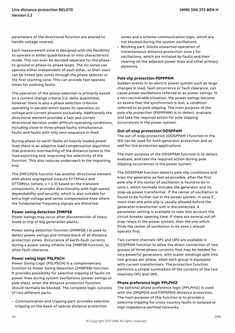
Each measurement zone is designed with the flexibilityto operate in either quadrilateral or mho characteristicmode. This can even be decided separate for the phase-to-ground or phase-to-phase loops. The six zones canoperate either independent of each other, or their startcan be linked (per zone) through the phase selector orthe first starting zone. This can provide fast operatetimes for evolving faults.
The operation of the phase-selection is primarily basedon a current change criteria (i.e. delta quantities),however there is also a phase selection criterionoperating in parallel which bases its operation onvoltage and current phasors exclusively. Additionally thedirectional element provides a fast and correctdirectional decision under difficult operating conditions,including close-in three-phase faults, simultaneousfaults and faults with only zero-sequence in-feed. Duringphase-to-earth faults on heavily loaded power linesthere is an adaptive load compensation algorithm thatprevents overreaching of the distance zones in the loadexporting end, improving the selectivity of the function.This also reduces underreach in the importing end.
High speed distance protection for series comp.lines, quad and mho characteristic ZMFCPDIS
GUID-C5C1ADD8-50A5-4485-848C-77D2222B56DC v8
The high speed distance protection (ZMFCPDIS)provides a sub-cycle, down towards a half-cycle operatetime. Its six zone, full scheme protection concept isentirely suitable in applications with single-phaseautoreclosing.
High speed distance protection ZMFCPDIS isfundamentally the same function as ZMFPDIS butprovides more flexibility in zone settings to suit morecomplex applications, such as series compensated lines.In operation for series compensated networks, the
Line distance protection REL670 1MRK 506 372-BEN HVersion 2.2
ABB 33© Copyright 2017 ABB. All rights reserved
parameters of the directional function are altered tohandle voltage reversal.
Each measurement zone is designed with the flexibilityto operate in either quadrilateral or mho characteristicmode. This can even be decided separate for the phase-to-ground or phase-to-phase loops. The six zones canoperate either independent of each other, or their startcan be linked (per zone) through the phase selector orthe first starting zone. This can provide fast operatetimes for evolving faults.
The operation of the phase-selection is primarily basedon a current change criteria (i.e. delta quantities),however there is also a phase selection criterionoperating in parallel which bases its operation onvoltage and current phasors exclusively. Additionally thedirectional element provides a fast and correctdirectional decision under difficult operating conditions,including close-in three-phase faults, simultaneousfaults and faults with only zero-sequence in-feed.
During phase-to-earth faults on heavily loaded powerlines there is an adaptive load compensation algorithmthat prevents overreaching of the distance zones in theload exporting end, improving the selectivity of thefunction. This also reduces underreach in the importingend.
The ZMFCPDIS function has another directional elementwith phase segregated outputs STTDFwLx andSTTDRVLx (where, x = 1-3) based on the transientcomponents. It provides directionality with high speed,dependability and security, which is also suitable forextra high voltage and series compensated lines wherethe fundamental frequency signals are distorted.
Power swing detection ZMRPSBM13873-3 v12
Power swings may occur after disconnection of heavyloads or trip of big generation plants.
Power swing detection function (ZMRPSB ) is used todetect power swings and initiate block of all distanceprotection zones. Occurrence of earth-fault currentsduring a power swing inhibits the ZMRPSB function, toallow fault clearance.
Power swing logic PSLPSCHSEMOD131350-4 v4
Power Swing Logic (PSLPSCH) is a complementaryfunction to Power Swing Detection (ZMRPSB) function.It provides possibility for selective tripping of faults onpower lines during system oscillations (power swings orpole slips), when the distance protection functionshould normally be blocked. The complete logic consistsof two different parts:
• Communication and tripping part: provides selectivetripping on the basis of special distance protection
zones and a scheme communication logic, which arenot blocked during the system oscillations.
• Blocking part: blocks unwanted operation ofinstantaneous distance protection zone 1 foroscillations, which are initiated by faults and theirclearing on the adjacent power lines and other primaryelements.
Pole slip protection PSPPPAMSEMOD143246-17 v7
Sudden events in an electric power system such as largechanges in load, fault occurrence or fault clearance, cancause power oscillations referred to as power swings. Ina non-recoverable situation, the power swings becomeso severe that the synchronism is lost, a conditionreferred to as pole slipping. The main purpose of thepole slip protection (PSPPPAM) is to detect, evaluate,and take the required action for pole slippingoccurrences in the power system.
Out-of-step protection OOSPPAMGUID-BF2F7D4C-F579-4EBD-9AFC-7C03296BD5D4 v8
The out-of-step protection (OOSPPAM ) function in theIED can be used for both generator protection and aswell for line protection applications.
The main purpose of the OOSPPAM function is to detect,evaluate, and take the required action during poleslipping occurrences in the power system.
The OOSPPAM function detects pole slip conditions andtrips the generator as fast as possible, after the firstpole-slip if the center of oscillation is found to be inzone 1, which normally includes the generator and itsstep-up power transformer. If the center of oscillation isfound to be further out in the power system, in zone 2,more than one pole-slip is usually allowed before thegenerator-transformer unit is disconnected. Aparameter setting is available to take into account thecircuit breaker opening time. If there are several out-of-step relays in the power system, then the one whichfinds the center of oscillation in its zone 1 shouldoperate first.
Two current channels I3P1 and I3P2 are available inOOSPPAM function to allow the direct connection of twogroups of three-phase currents; that may be needed forvery powerful generators, with stator windings split intotwo groups per phase, when each group is equippedwith current transformers. The protection functionperforms a simple summation of the currents of the twochannels I3P1 and I3P2.
Phase preference logic PPLPHIZSEMOD153619-5 v3
The optional phase preference logic (PPLPHIZ) is usedwith the ZMQPDIS and FDPSPDIS distance protection.The main purpose of this function is to provide aselective tripping for cross-country faults in isolated orhigh impedance-earthed networks.
Line distance protection REL670 1MRK 506 372-BEN HVersion 2.2
34 ABB© Copyright 2017 ABB. All rights reserved

Phase preference logic PPL2PHIZGUID-39785DEB-E5D7-447C-977B-9E940CA8E774 v1
The Phase preference logic function (PPL2PHIZ) is usedwith the high speed distance protection, quad and mhocharacteristic (ZMFPDIS). It is intended to be used inisolated or high impedance earthed networks wherethere is a requirement to operate on only one of thefaulty lines during a cross-country fault. It can be usedwithout preference to restrain operation for single earthfaults with a delayed zero-sequence current release.
For cross-country faults, the logic selects either theleading or lagging phase-earth loop for measurement. Itinitiates operation on the preferred fault based on theselected phase preference. A number of different phasepreference combinations are available for selection.
PPL2PHIZ provides an additional phase selectioncriteria, namely under voltage criteria, suitable forcross-country faults. In radial networks, where there isno fault current in the phase with the external fault,current or impedance based phase selection methodsbecome ineffective. Hence, only voltage can be used forphase selection. The phase selection result will be thesame for all bays on a bus since the voltage is the same,which is an important condition for operating withphase preference.
In meshed and stronger networks, it is difficult to findappropriate under-voltage or phase selection settings. IfPPL2PHIZ is unable to detect both faulty phases, then itis not possible to provide preference. The distanceprotection will still be released however, withoutpreference. The final result might be that both faultyfeeders are operated. In other words, operation isprioritized over strict adherence to preference.
Automatic switch onto fault logic, voltage andcurrent based ZCVPSOF
M13829-3 v4
Automatic switch onto fault logic (ZCVPSOF) is afunction that gives an instantaneous trip at closing ofbreaker onto a fault. A dead line detection check isprovided to activate the function when the line is dead.
6. Wide area measurement system
Synchrophasor report, 8 phasorsGUID-7539462D-A3D6-492D-9926-E67C5B7C72D9 v1
Configuration parameters for IEEE1344 and C37.118protocol PMUCONF
GUID-33694C62-A109-4D8F-9063-CEFA5D0E78BC v4
The IED supports the following IEEE synchrophasorstandards:
• IEEE 1344-1995 (Both measurements and datacommunication)
• IEEE Std C37.118-2005 (Both measurements and datacommunication)
• IEEE Std C37.118.1–2011 and C37.118.1a-2014(Measurements)
• IEEE Std C37.118.2-2011 (Data communication)
PMUCONF contains the PMU configuration parametersfor both IEEE C37.118 and IEEE 1344 protocols. Thismeans all the required settings and parameters in orderto establish and define a number of TCP and/or UDPconnections with one or more PDC clients(synchrophasor client). This includes port numbers,TCP/UDP IP addresses, and specific settings for IEEEC37.118 as well as IEEE 1344 protocols.
Protocol reporting via IEEE 1344 and C37.118PMUREPORT
GUID-8DF29209-252A-4E51-9F4A-B14B669E71AB v4
The phasor measurement reporting block moves thephasor calculations into an IEEE C37.118 and/or IEEE1344 synchrophasor frame format. The PMUREPORTblock contains parameters for PMU performance classand reporting rate, the IDCODE and Global PMU ID,format of the data streamed through the protocol, thetype of reported synchrophasors, as well as settings forreporting analog and digital signals.
The message generated by the PMUREPORT functionblock is set in accordance with the IEEE C37.118 and/orIEEE 1344 standards.
There are settings for Phasor type (positive sequence,negative sequence or zero sequence in case of 3-phasephasor and L1, L2 or L3 in case of single phase phasor),PMU's Service class (Protection or Measurement),Phasor representation (polar or rectangular) and thedata types for phasor data, analog data and frequencydata.
Synchrophasor data can be reported to up to 8 clientsover TCP and/or 6 UDP group clients for multicast orunicast transmission of phasor data from the IED. Moreinformation regarding synchrophasor communicationstructure and TCP/UDP configuration is available inApplication Manual under section C37.118 PhasorMeasurement Data Streaming Protocol Configuration.
Multiple PMU functionality can be configured in the IED,which can stream out same or different data at differentreporting rates or different performance (service)classes.
Line distance protection REL670 1MRK 506 372-BEN HVersion 2.2
ABB 35© Copyright 2017 ABB. All rights reserved

7. Current protection
Instantaneous phase overcurrent protection PHPIOCM12910-3 v14
The instantaneous three phase overcurrent (PHPIOC)function has a low transient overreach and shorttripping time to allow use as a high set short-circuitprotection function.
Directional phase overcurrent protection, four stepsOC4PTOC
M12846-3 v17
Directional phase overcurrent protection, four steps(OC4PTOC) has an inverse or definite time delay for eachstep.
All IEC and ANSI inverse time characteristics areavailable together with an optional user defined timecharacteristic.
The directional function needs voltage as it is voltagepolarized with memory. The function can be set to bedirectional or non-directional independently for each ofthe steps.
A second harmonic blocking level can be set for thefunction and can be used to block each step individually.
Instantaneous residual overcurrent protectionEFPIOC
M12701-3 v16
The Instantaneous residual overcurrent protection(EFPIOC) has a low transient overreach and shorttripping times to allow the use for instantaneous earth-fault protection, with the reach limited to less than thetypical eighty percent of the line at minimum sourceimpedance. EFPIOC is configured to measure theresidual current from the three-phase current inputs andcan be configured to measure the current from aseparate current input.
Directional residual overcurrent protection, foursteps EF4PTOC
M13667-3 v19
Directional residual overcurrent protection, four steps(EF4PTOC) can be used as main protection for phase-to-earth faults. It can also be used to provide a systemback-up, for example, in the case of the primaryprotection being out of service due to communication orvoltage transformer circuit failure.
EF4PTOC has an inverse or definite time delayindependent for each step.
All IEC and ANSI time-delayed characteristics areavailable together with an optional user-definedcharacteristic.
EF4PTOC can be set to be directional or non-directionalindependently for each step.
IDir, UPol and IPol can be independently selected to beeither zero sequence or negative sequence.
A second harmonic blocking can be set individually foreach step.
Directional operation can be combined together withthe corresponding communication logic in permissive orblocking teleprotection scheme. The current reversaland weak-end infeed functionality are available as well.
The residual current can be calculated by summing thethree-phase currents or taking the input from theneutral CT.
Four step directional negative phase sequenceovercurrent protection NS4PTOC
GUID-485E9D36-0032-4559-9204-101539A32F47 v6
Four step directional negative phase sequenceovercurrent protection (NS4PTOC) has an inverse ordefinite time delay independent for each stepseparately.
All IEC and ANSI time delayed characteristics areavailable together with an optional user definedcharacteristic.
The directional function is voltage polarized.
NS4PTOC can be set directional or non-directionalindependently for each of the steps.
NS4PTOC can be used as main protection forunsymmetrical fault; phase-phase short circuits, phase-phase-earth short circuits and single phase earth faults.
NS4PTOC can also be used to provide a system backupfor example, in the case of the primary protection beingout of service due to communication or voltagetransformer circuit failure.
Directional operation can be combined together withcorresponding communication logic in permissive orblocking teleprotection scheme. The same logic as fordirectional zero sequence current can be used. Currentreversal and weak-end infeed functionality are available.
Sensitive directional residual overcurrent and powerprotection SDEPSDE
SEMOD171438-5 v6
In isolated networks or in networks with high impedanceearthing, the earth fault current is significantly smallerthan the short circuit currents. In addition to this, themagnitude of the fault current is almost independent onthe fault location in the network. The protection can beselected to use either the residual current or residualpower component 3U0·3I0·cos j, for operating quantitywith maintained short circuit capacity. There is alsoavailable one nondirectional 3I0 step and one 3U0overvoltage tripping step.
Line distance protection REL670 1MRK 506 372-BEN HVersion 2.2
36 ABB© Copyright 2017 ABB. All rights reserved

No specific sensitive current input is needed. Sensitivedirectional residual overcurrent and power protection(SDEPSDE) can be set as low 0.25% of IBase.
Thermal overload protection, one time constantLCPTTR/LFPTTR
M12020-4 v14
The increasing utilization of the power system closer tothe thermal limits has generated a need of a thermaloverload protection for power lines.
A thermal overload will often not be detected by otherprotection functions and the introduction of the thermaloverload protection can allow the protected circuit tooperate closer to the thermal limits.
The three-phase current measuring protection has an I2tcharacteristic with settable time constant and a thermalmemory. The temperature is displayed in either Celsiusor Fahrenheit, depending on whether the function usedis Thermal overload protection (LCPTTR) (Celsius) or(LFPTTR) (Fahrenheit).
An alarm level gives early warning to allow operators totake action well before the line is tripped.
Estimated time to trip before operation, and estimatedtime to reclose after operation are presented.
Breaker failure protection CCRBRFM11550-6 v18
Breaker failure protection (CCRBRF) ensures a fastbackup tripping of the surrounding breakers in case theown breaker fails to open. CCRBRF measurementcriterion can be current based, CB position based or anadaptive combination of these two conditions.
A current based check with extremely short reset time isused as check criterion to achieve high security againstinadvertent operation.
CB position check criteria can be used where the faultcurrent through the breaker is small.
CCRBRF provides three different options to select howt1 and t2 timers are run:1. By external start signals which is internally latched2. Follow external start signal only3. Follow external start signal and the selected
FunctionMode
CCRBRF can be single- or three- phase initiated to allowits use with single phase tripping applications. For thethree-phase application of the CCRBRF the currentcriteria can be set to operate only if “2 elementsoperates out of three phases and neutral” for example;two phases or one phase plus the residual current start.This gives a higher security to the backup trip command.
The CCRBRF function can be programmed to give asingle- or three- phase retrip to its own breaker to avoid
unnecessary tripping of surrounding breakers at anincorrect initiation due to mistakes during testing.
Stub protection STBPTOCM12902-3 v10
When a power line is taken out of service formaintenance and the line disconnector is opened inmulti-breaker arrangements the voltage transformerswill mostly be outside on the disconnected part. Theprimary line distance protection will thus not be able tooperate and must be blocked.
The stub protection (STBPTOC) covers the zone betweenthe current transformers and the open disconnector.The three-phase instantaneous overcurrent function isreleased from a normally open, NO (b) auxiliary contacton the line disconnector.
Pole discordance protection CCPDSCM13269-3 v15
An open phase can cause negative and zero sequencecurrents which cause thermal stress on rotatingmachines and can cause unwanted operation of zerosequence or negative sequence current functions.
Normally the own breaker is tripped to correct such asituation. If the situation persists the surroundingbreakers should be tripped to clear the unsymmetricalload situation.
The Pole discordance protection function (CCPDSC)operates based on information from auxiliary contactsof the circuit breaker for the three phases withadditional criteria from unsymmetrical phase currentswhen required.
Directional over/underpower protection GOPPDOP/GUPPDUP
SEMOD175421-4 v7
The directional over-/under-power protection(GOPPDOP/GUPPDUP) can be used wherever a high/lowactive, reactive or apparent power protection oralarming is required. The functions can alternatively beused to check the direction of active or reactive powerflow in the power system. There are a number ofapplications where such functionality is needed. Someof them are:
• detection of reversed active power flow• detection of high reactive power flow
Each function has two steps with definite time delay.
Broken conductor check BRCPTOCSEMOD171446-5 v2
The main purpose of the function Broken conductorcheck (BRCPTOC) is the detection of broken conductorson protected power lines and cables (series faults).Detection can be used to give alarm only or trip the linebreaker.
Line distance protection REL670 1MRK 506 372-BEN HVersion 2.2
ABB 37© Copyright 2017 ABB. All rights reserved

Voltage-restrained time overcurrent protectionVRPVOC
GUID-935E1CE8-601F-40E2-8D22-2FF68420FADF v6
Voltage-restrained time overcurrent protection(VRPVOC) function can be used as generator backupprotection against short-circuits.
The overcurrent protection feature has a settablecurrent level that can be used either with definite timeor inverse time characteristic. Additionally, it can bevoltage controlled/restrained.
One undervoltage step with definite time characteristicis also available within the function in order to providefunctionality for overcurrent protection withundervoltage seal-in.
8. Voltage protection
Two-step undervoltage protection UV2PTUVM13789-3 v12
Undervoltages can occur in the power system duringfaults or abnormal conditions. The two-stepundervoltage protection function (UV2PTUV) can beused to open circuit breakers to prepare for systemrestoration at power outages or as a long-time delayedback-up to the primary protection.
UV2PTUV has two voltage steps, each with inverse ordefinite time delay.
It has a high reset ratio to allow settings close to thesystem service voltage.
Two step overvoltage protection OV2PTOVM13798-3 v16
Overvoltages may occur in the power system duringabnormal conditions such as sudden power loss, tapchanger regulating failures, and open line ends on longlines.
Two step overvoltage protection (OV2PTOV) functioncan be used to detect open line ends, normally thencombined with a directional reactive over-powerfunction to supervise the system voltage. Whentriggered, the function will cause an alarm, switch inreactors, or switch out capacitor banks.
OV2PTOV has two voltage steps, each of them withinverse or definite time delayed.
OV2PTOV has a high reset ratio to allow settings closeto system service voltage.
Two step residual overvoltage protection ROV2PTOVM13808-3 v11
Residual voltages may occur in the power system duringearth faults.
Two step residual overvoltage protection (ROV2PTOV)function calculates the residual voltage from the three-
phase voltage input transformers or measures it from asingle voltage input transformer fed from an open deltaor neutral point voltage transformer.
ROV2PTOV has two voltage steps, each with inverse ordefinite time delay.
A reset delay ensures operation for intermittent earthfaults.
Overexcitation protection OEXPVPHM13319-3 v9
When the laminated core of a power transformer orgenerator is subjected to a magnetic flux densitybeyond its design limits, stray flux will flow into non-laminated components that are not designed to carryflux. This will cause eddy currents to flow. These eddycurrents can cause excessive heating and severedamage to insulation and adjacent parts in a relativelyshort time. The function has settable inverse operatingcurves and independent alarm stages.
Voltage differential protection VDCPTOVSEMOD153862-5 v7
A voltage differential monitoring function is available. Itcompares the voltages from two three phase sets ofvoltage transformers and has one sensitive alarm stepand one trip step.
Loss of voltage check LOVPTUVSEMOD171457-5 v8
Loss of voltage check (LOVPTUV ) is suitable for use innetworks with an automatic system restorationfunction. LOVPTUV issues a three-pole trip command tothe circuit breaker, if all three phase voltages fall belowthe set value for a time longer than the set time and thecircuit breaker remains closed.
The operation of LOVPTUV is supervised by the fusefailure supervision FUFSPVC.
Radial feeder protection PAPGAPCGUID-82856D0B-5C5E-499A-9A62-CC511E4F047A v3
The radial feeder protection (PAPGAPC) function is usedto provide protection of radial feeders having passiveloads or weak end in-feed sources. It is possible toachieve fast tripping using communication system withremote end or delayed tripping not requiringcommunication or upon communication system failure.For fast tripping, scheme communication is required.Delayed tripping does not require schemecommunication.
The PAPGAPC function performs phase selection usingmeasured voltages. Each phase voltage is compared tothe opposite phase-phase voltage. A phase is deemed tohave a fault if its phase voltage drops below a settablepercentage of the opposite phase-phase voltage. Thephase - phase voltages include memory. This memoryfunction has a settable time constant.
The voltage-based phase selection is used for both fastand delayed tripping. To achieve fast tripping, scheme
Line distance protection REL670 1MRK 506 372-BEN HVersion 2.2
38 ABB© Copyright 2017 ABB. All rights reserved

communication is required. Delayed tripping does notrequire scheme communication. It is possible to permitdelayed tripping only upon failure of thecommunications channel by blocking the delayedtripping logic with a communications channel healthyinput signal.
On receipt of the communications signal, phaseselective outputs for fast tripping are set based on thephase(s) in which the phase selection function hasoperated.
For delayed tripping, single pole and three pole delaysare separately and independently settable. Furthermore,it is possible to enable or disable single pole and threepole delayed tripping. For single phase faults, it ispossible to include a residual current check in thetripping logic. Three pole tripping is always selected forphase selection on more than one phase. Three poletripping will also occur if the residual current exceedsthe set level during fuse failure for a time longer thanthe three pole trip delay time.
9. Frequency protection
Underfrequency protection SAPTUFM13349-3 v13
Underfrequency occurs as a result of a lack ofgeneration in the network.
Underfrequency protection (SAPTUF) measuresfrequency with high accuracy, and is used for loadshedding systems, remedial action schemes, gas turbinestartup and so on. Separate definite time delays areprovided for operate and restore.
SAPTUF is provided with undervoltage blocking.
The operation is based on positive sequence voltagemeasurement and requires two phase-phase or threephase-neutral voltages to be connected.
Overfrequency protection SAPTOFM14953-3 v12
Overfrequency protection function (SAPTOF) isapplicable in all situations, where reliable detection ofhigh fundamental power system frequency is needed.
Overfrequency occurs because of sudden load drops orshunt faults in the power network. Close to thegenerating plant, generator governor problems can alsocause over frequency.
SAPTOF measures frequency with high accuracy, and isused mainly for generation shedding and remedialaction schemes. It is also used as a frequency stageinitiating load restoring. A definite time delay isprovided for operate.
SAPTOF is provided with an undervoltage blocking.
The operation is based on positive sequence voltagemeasurement and requires two phase-phase or threephase-neutral voltages to be connected.
Rate-of-change of frequency protection SAPFRCM14965-3 v14
The rate-of-change of frequency protection function(SAPFRC) gives an early indication of a main disturbancein the system. SAPFRC measures frequency with highaccuracy, and can be used for generation shedding, loadshedding and remedial action schemes. SAPFRC candiscriminate between a positive or negative change offrequency. A definite time delay is provided for operate.
SAPFRC is provided with an undervoltage blocking. Theoperation is based on positive sequence voltagemeasurement and requires two phase-phase or threephase-neutral voltages to be connected.
10. Multipurpose protection
General current and voltage protection CVGAPCM13083-11 v9
The General current and voltage protection (CVGAPC)can be utilized as a negative sequence currentprotection detecting unsymmetrical conditions such asopen phase or unsymmetrical faults.
CVGAPC can also be used to improve phase selection forhigh resistive earth faults, outside the distanceprotection reach, for the transmission line. Threefunctions are used, which measures the neutral currentand each of the three phase voltages. This will give anindependence from load currents and this phaseselection will be used in conjunction with the detectionof the earth fault from the directional earth faultprotection function.
11. General calculation
Multipurpose filter SMAIHPACGUID-EB0B11C3-FF79-4B8D-A335-649623E832F9 v3
The multi-purpose filter function block (SMAIHPAC) isarranged as a three-phase filter. It has very much thesame user interface (e.g. inputs and outputs) as thestandard pre-processing function block SMAI. Howeverthe main difference is that it can be used to extract anyfrequency component from the input signal. Thus it can,for example, be used to build sub-synchronousresonance protection for synchronous generator.
Line distance protection REL670 1MRK 506 372-BEN HVersion 2.2
ABB 39© Copyright 2017 ABB. All rights reserved

12. Secondary system supervision
Current circuit supervision CCSSPVCM12444-3 v10
Open or short circuited current transformer cores cancause unwanted operation of many protection functionssuch as differential, earth-fault current and negative-sequence current functions.
Current circuit supervision (CCSSPVC) compares theresidual current from a three phase set of currenttransformer cores with the neutral point current on aseparate input taken from another set of cores on thecurrent transformer.
A detection of a difference indicates a fault in the circuitand is used as alarm or to block protection functionsexpected to give inadvertent tripping.
Fuse failure supervision FUFSPVCSEMOD113820-4 v12
The aim of the fuse failure supervision function(FUFSPVC) is to block voltage measuring functions atfailures in the secondary circuits between the voltagetransformer and the IED in order to avoid inadvertentoperations that otherwise might occur.
The fuse failure supervision function basically has threedifferent detection methods, negative sequence andzero sequence based detection and an additional deltavoltage and delta current detection.
The negative sequence detection algorithm isrecommended for IEDs used in isolated or high-impedance earthed networks. It is based on thenegative-sequence quantities.
The zero sequence detection is recommended for IEDsused in directly or low impedance earthed networks. It isbased on the zero sequence measuring quantities.
The selection of different operation modes is possibleby a setting parameter in order to take into account theparticular earthing of the network.
A criterion based on delta current and delta voltagemeasurements can be added to the fuse failuresupervision function in order to detect a three phasefuse failure, which in practice is more associated withvoltage transformer switching during stationoperations.
Fuse failure supervision VDSPVCGUID-6AF2219A-264F-4971-8D03-3B8A9D0CB284 v5
Different protection functions within the protection IEDoperates on the basis of measured voltage at the relaypoint. Some example of protection functions are:
• Distance protection function.• Undervoltage function.• Energisation function and voltage check for the weak
infeed logic.
These functions can operate unintentionally, if a faultoccurs in the secondary circuits between voltageinstrument transformers and the IED. Theseunintentional operations can be prevented by fusefailure supervision (VDSPVC).
VDSPVC is designed to detect fuse failures or faults involtage measurement circuit, based on phase wisecomparison of voltages of main and pilot fused circuits.VDSPVC blocking output can be configured to blockfunctions that need to be blocked in case of faults in thevoltage circuit.
Voltage based delta supervision DELVSPVCGUID-6188C4C1-E1D5-421A-B496-96676287EBB2 v2
Delta supervision function is used to quickly detect(sudden) changes in the network. This can, for example,be used to detect faults in the power system networksand islanding in grid networks. Voltage based deltasupervision (DELVSPVC) is needed at the gridinterconnection point.
Current based delta supervision DELISPVCGUID-30A00AE0-8D3A-4CE8-9379-8D1A0A6078E3 v2
Delta supervision function is used to quickly detect(sudden) changes in the network. This can, for example,be used to detect disturbances in the power systemnetwork. Current based delta supervision (DELISPVC)provides selectivity between load change and the fault.
Present power system has many power electronicdevices or FACTS devices, which injects a large numberof harmonics into the system. The function hasadditional features of 2nd harmonic blocking and 3rd
harmonic start level adaption. The 2nd harmonic blockingsecures the operation during the transformer charging,when high inrush currents are supplied into the system.
Delta supervision of real input DELSPVCGUID-8FAD2CCF-091F-4CDB-8ABF-1BDC874A8403 v2
Delta supervision functions are used to quickly detect(sudden) changes in the power system. Real input deltasupervision (DELSPVC) function is a general deltafunction. It is used to detect the change measuredqualities over a settable time period, such as:• Power• Reactive power• Temperature• Frequency• Power factor
Line distance protection REL670 1MRK 506 372-BEN HVersion 2.2
40 ABB© Copyright 2017 ABB. All rights reserved

13. Control
Synchrocheck, energizing check, and synchronizingSESRSYN
M12480-3 v16
The Synchronizing function allows closing ofasynchronous networks at the correct moment includingthe breaker closing time, which improves the networkstability.
Synchrocheck, energizing check, and synchronizing(SESRSYN) function checks that the voltages on bothsides of the circuit breaker are in synchronism, or withat least one side dead to ensure that closing can bedone safely.
SESRSYN function includes a built-in voltage selectionscheme for double bus and 1½ breaker or ring busbararrangements.
Manual closing as well as automatic reclosing can bechecked by the function and can have different settings.
For systems, which can run asynchronously, asynchronizing feature is also provided. The mainpurpose of the synchronizing feature is to providecontrolled closing of circuit breakers when twoasynchronous systems are in phase and can beconnected. The synchronizing feature evaluates voltagedifference, phase angle difference, slip frequency andfrequency rate of change before issuing a controlledclosing of the circuit breaker. Breaker closing time is asetting.
Autorecloser SMBRRECM12390-3 v17
The auto recloser (SMBRREC) function provides:• high-speed and/or delayed auto reclosing• single and/or three phase auto reclosing• support for single or multi-breaker applications.
The auto recloser can be used for delayed busbarrestoration.
Up to five reclosing shots can be performed. The firstshot can be single-, two-, and /or three-phasedepending on the type of the fault and the selected autoreclosing mode.
Several auto reclosing functions can be provided formulti-breaker arrangements. A priority circuit allows onecircuit breaker to reclose first and the second will onlyclose if the fault proved to be transient.
Each auto reclosing function can be configured to co-operate with the synchrocheck function.
Apparatus control APC
M13444-3 v15
The apparatus control functions are used for control andsupervision of circuit breakers, disconnectors andearthing switches within a bay. Permission to operate isgiven after evaluation of conditions from otherfunctions such as interlocking, synchrocheck, operatorplace selection and external or internal blockings.
The complete apparatus controlfunction is not included in this product,and the information below is includedfor understanding of the principle forthe use of QCBAY, LOCREM, andLOCREMCTRL.
Apparatus control features:• Select-Execute principle to give high reliability• Selection function to prevent simultaneous operation• Selection and supervision of operator place• Command supervision• Block/deblock of operation• Block/deblock of updating of position indications• Substitution of position and quality indications• Overriding of interlocking functions• Overriding of synchrocheck• Operation counter• Suppression of mid position
Two types of command models can be used:• Direct with normal security• SBO (Select-Before-Operate) with enhanced security
Normal security means that only the command isevaluated and the resulting position is not supervised.Enhanced security means that the command isevaluated with an additional supervision of the statusvalue of the control object. The command sequence withenhanced security is always terminated by aCommandTermination service primitive and anAddCause telling if the command was successful or ifsomething went wrong.
Control operation can be performed from the local HMIwith authority control if so defined.
InterlockingM13531-3 v4
The interlocking function blocks the possibility tooperate primary switching devices, for instance when adisconnector is under load, in order to prevent materialdamage and/or accidental human injury.
Each apparatus control function has interlockingmodules included for different switchyardarrangements, where each function handles interlockingof one bay. The interlocking function is distributed toeach IED and is not dependent on any central function.
Line distance protection REL670 1MRK 506 372-BEN HVersion 2.2
ABB 41© Copyright 2017 ABB. All rights reserved

For the station-wide interlocking, the IEDs communicatevia the system-wide interbay bus (IEC 61850-8-1) or byusing hard wired binary inputs/outputs. Theinterlocking conditions depend on the circuitconfiguration and apparatus position status at anygiven time.
For easy and safe implementation of the interlockingfunction, the IED is delivered with standardized andtested software interlocking modules containing logicfor the interlocking conditions. The interlockingconditions can be altered, to meet the customer’sspecific requirements, by adding configurable logic bymeans of the graphical configuration tool.
Switch controller SCSWIM13486-3 v10
The Switch controller (SCSWI) initializes and supervisesall functions to properly select and operate switchingprimary apparatuses. The Switch controller may handleand operate on one multi-phase device or up to threeone-phase devices.
Circuit breaker SXCBRM13489-3 v6
The purpose of Circuit breaker (SXCBR) is to provide theactual status of positions and to perform the controloperations, that is, pass all the commands to primaryapparatuses in the form of circuit breakers via binaryoutput boards and to supervise the switching operationand position.
Circuit switch SXSWIM16492-3 v6
The purpose of Circuit switch (SXSWI) function is toprovide the actual status of positions and to performthe control operations, that is, pass all the commands toprimary apparatuses in the form of disconnectors orearthing switches via binary output boards and tosupervise the switching operation and position.
Reservation function QCRSVM13506-3 v5
The purpose of the reservation (QCRSV) function isprimarily to transfer interlocking information betweenIEDs in a safe way and to prevent double operation in abay, switchyard part, or complete substation.
Reservation input RESINM16501-3 v5
The Reservation input (RESIN) function receives thereservation information from other bays. The number ofinstances is the same as the number of involved bays(up to 60 instances are available).
Bay control QCBAYM13447-3 v8
The Bay control (QCBAY) function is used together withLocal remote and local remote control functions tohandle the selection of the operator place per bay.QCBAY also provides blocking functions that can bedistributed to different apparatuses within the bay.
Proxy for signals from switching device via GOOSEXLNPROXY
GUID-11F9CA1C-8E20-489B-822B-34DACC59553A v1
The proxy for signals from switching device via GOOSE(XLNPROXY) gives an internal representation of theposition status and control response for a switchmodelled in a breaker IED. This representation isidentical to that of an SXCBR or SXSWI function.
GOOSE function block to receive a switching deviceGOOSEXLNRCV
GUID-5AC7DE11-CB95-4565-A8AE-FB23D59FD717 v1
The GOOSE XLN Receive component is used to collectinformation from another device’s XCBR/XSWI logicalnode sent over process bus via GOOSE. The GOOSE XLNReceive component includes 12 different outputs (andtheir respective channel valid bits) with defined namesto ease the 61850 mapping of the GOOSE signals in theconfiguration process.
Local remote LOCREM/Local remote controlLOCREMCTRL
M17086-3 v11
The signals from the local HMI or from an external local/remote switch are connected via the function blockslocal remote (LOCREM) and local remote control(LOCREMCTRL) to the Bay control (QCBAY) functionblock. The parameter ControlMode in function blockLOCREM is set to choose if the switch signals arecoming from the local HMI or from an external hardwareswitch connected via binary inputs.
Logic rotating switch for function selection andLHMI presentation SLGAPC
SEMOD114908-4 v11
The logic rotating switch for function selection andLHMI presentation (SLGAPC) (or the selector switchfunction block) is used to get an enhanced selectorswitch functionality compared to the one provided by ahardware selector switch. Hardware selector switchesare used extensively by utilities, in order to havedifferent functions operating on pre-set values.Hardware switches are however sources formaintenance issues, lower system reliability and anextended purchase portfolio. The selector switchfunction eliminates all these problems.
Selector mini switch VSGAPCSEMOD158756-5 v10
The Selector mini switch (VSGAPC) function block is amultipurpose function used for a variety of applications,as a general purpose switch.
VSGAPC can be controlled from the menu, from a symbolon the single line diagram (SLD) on the local HMI or fromBinary inputs.
Generic communication function for Double Pointindication DPGAPC
SEMOD55850-5 v7
Generic communication function for Double Pointindication (DPGAPC) function block is used to senddouble point position indications to other systems,equipment or functions in the substation through IEC61850-8-1 or other communication protocols. It is
Line distance protection REL670 1MRK 506 372-BEN HVersion 2.2
42 ABB© Copyright 2017 ABB. All rights reserved

especially intended to be used in the interlockingstation-wide logics.
Single point generic control 8 signals SPC8GAPCSEMOD176462-4 v11
The Single point generic control 8 signals (SPC8GAPC)function block is a collection of 8 single pointcommands that can be used for direct commands forexample reset of LEDs or putting IED in "ChangeLock"state from remote. In this way, simple commands can besent directly to the IED outputs, without confirmation.Confirmation (status) of the result of the commands issupposed to be achieved by other means, such as binaryinputs and SPGAPC function blocks. The commands canbe pulsed or steady with a settable pulse time.
Automation bits, command function for DNP3.0AUTOBITS
SEMOD158591-5 v8
Automation bits function for DNP3 (AUTOBITS) is usedwithin PCM600 to get into the configuration of thecommands coming through the DNP3 protocol. TheAUTOBITS function plays the same role as functionsGOOSEBINRCV (for IEC 61850) and MULTICMDRCV (forLON).
Single command, 16 signalsM12446-6 v5
The IEDs can receive commands either from asubstation automation system or from the local HMI.The command function block has outputs that can beused, for example, to control high voltage apparatusesor for other user defined functionality.
14. Scheme communication
Scheme communication logic with delta basedblocking scheme signal transmit ZCPSCH
M13860-3 v11
To achieve instantaneous fault clearance for all linefaults, scheme communication logic is provided. Alltypes of communication schemes for permissiveunderreaching, permissive overreaching, blocking, deltabased blocking, unblocking and intertrip are available.
The built-in communication module (LDCM) can be usedfor scheme communication signaling when included.
Phase segregated scheme communication logic fordistance protection ZC1PPSCH
SEMOD141686-4 v3
Communication between line ends is used to achievefault clearance for all faults on a power line. All possibletypes of communication schemes for example,permissive underreach, permissive overreach andblocking schemes are available. To manage problemswith simultaneous faults on parallel power lines phasesegregated communication is needed. This will thenreplace the standard Scheme communication logic fordistance or Overcurrent protection (ZCPSCH) onimportant lines where three communication channels (in
each subsystem) are available for the distanceprotection communication.
The main purpose of the Phase segregated schemecommunication logic for distance protection(ZC1PPSCH) function is to supplement the distanceprotection function such that:
• fast clearance of faults is also achieved at the line endfor which the faults are on the part of the line notcovered by its underreaching zone.
• correct phase selection can be maintained to supportsingle-pole tripping for faults occurring anywhere onthe entire length of a double circuit line.
To accomplish this, three separate communicationchannels, that is, one per phase, each capable oftransmitting a signal in each direction is required.
ZC1PPSCH can be completed with the current reversaland WEI logic for phase segregated communication,when found necessary in Blocking and Permissiveoverreaching schemes.
Current reversal and weak-end infeed logic fordistance protection ZCRWPSCH
M13896-3 v15
The ZCRWPSCH function provides the current reversaland weak end infeed logic functions that supplementthe standard scheme communication logic. It is notsuitable for standalone use as it requires inputs fromthe distance protection functions and the schemecommunications function included within the terminal.
On detection of a current reversal, the current reversallogic provides an output to block the sending of theteleprotection signal to the remote end, and to blockthe permissive tripping at the local end. This blockingcondition is maintained long enough to ensure that nounwanted operation will occur as a result of the currentreversal.
On verification of a weak end infeed condition, the weakend infeed logic provides an output for sending thereceived teleprotection signal back to the remotesending end and other output(s) for local tripping. Forterminals equipped for single- and two-pole tripping,outputs for the faulted phase(s) are provided.Undervoltage detectors are used to detect the faultedphase(s).
Current reversal and weak-end infeed logic for phasesegregated communication ZC1WPSCH
SEMOD156473-5 v3
Current reversal and weak-end infeed logic for phasesegregated communication (ZC1WPSCH) function isused to prevent unwanted operations due to currentreversal when using permissive overreach protectionschemes in application with parallel lines where theoverreach from the two ends overlaps on the parallelline.
Line distance protection REL670 1MRK 506 372-BEN HVersion 2.2
ABB 43© Copyright 2017 ABB. All rights reserved

The weak-end infeed logic is used in cases where theapparent power behind the protection can be too low toactivate the distance protection function. Whenactivated, received carrier signal together with localundervoltage criteria and no reverse zone operationgives an instantaneous trip. The received signal is alsoechoed back to accelerate the sending end.
Local acceleration logic ZCLCPSCHM13823-3 v7
To achieve fast clearing of faults on the whole line, whenno communication channel is available, localacceleration logic (ZCLCPSCH) can be used. This logicenables fast fault clearing and re-closing during certainconditions, but naturally, it can not fully replace acommunication channel.
The logic can be controlled either by the autorecloser(zone extension) or by the loss-of-load current (loss-of-load acceleration).
Scheme communication logic for residualovercurrent protection ECPSCH
M13918-4 v11
To achieve fast fault clearance of earth faults on thepart of the line not covered by the instantaneous step ofthe residual overcurrent protection, the directionalresidual overcurrent protection can be supported with alogic that uses communication channels.
In the directional scheme, information of the faultcurrent direction must be transmitted to the other lineend. With directional comparison, a short operate timeof the protection including a channel transmission time,can be achieved. This short operate time enables rapidautoreclosing function after the fault clearance.
The communication logic module for directional residualcurrent protection enables blocking as well aspermissive under/overreaching, and unblockingschemes. The logic can also be supported by additionallogic for weak-end infeed and current reversal, includedin Current reversal and weak-end infeed logic forresidual overcurrent protection (ECRWPSCH) function.
Current reversal and weak-end infeed logic forresidual overcurrent protection ECRWPSCH
M13928-3 v8
The Current reversal and weak-end infeed logic forresidual overcurrent protection (ECRWPSCH) is asupplement to Scheme communication logic for residualovercurrent protection ECPSCH.
To achieve fast fault clearing for all earth faults on theline, the directional earth fault protection function canbe supported with logic that uses tele-protectionchannels.
This is why the IEDs have available additions to thescheme communication logic.
M13928-6 v2
If parallel lines are connected to common busbars atboth terminals, overreaching permissive communicationschemes can trip unselectively due to fault currentreversal. This unwanted tripping affects the healthy linewhen a fault is cleared on the other line. This lack ofsecurity can result in a total loss of interconnectionbetween the two buses. To avoid this type ofdisturbance, a fault current reversal logic (transientblocking logic) can be used.
M13928-8 v5
Permissive communication schemes for residualovercurrent protection can basically operate only whenthe protection in the remote IED can detect the fault.The detection requires a sufficient minimum residualfault current, out from this IED. The fault current can betoo low due to an opened breaker or high-positiveand/or zero-sequence source impedance behind thisIED. To overcome these conditions, weak-end infeed(WEI) echo logic is used. The weak-end infeed echo islimited to 200 ms to avoid channel lockup.
Direct transfer trip DTTLow active power and power factor protection LAPPGAPC
GUID-25A2A94F-09FE-4552-89F8-CF22632A7A0D v2
Low active power and power factor protection(LAPPGAPC) function measures power flow. It can beused for protection and monitoring of:
• phase wise low active power• phase wise low power factor• phase wise reactive power and apparent power as
service values
Following features are available:
• Definite time stage for low active power protection• Definite time stage for low power factor protection• Individual enabling of Low active power and Low
power factor functions• Low active power trip with 2 selection modes '1 out of
3' and '2 out of 3'• Phase wise calculated values of apparent power,
reactive power, active power and power factor areavailable as service values
• Insensitive to small variations in voltage and current
Compensated over and undervoltage protectionCOUVGAPC
GUID-229EB419-0903-46FA-9192-BBB35725C841 v2
Compensated over and undervoltage protection(COUVGAPC) function calculates the remote end voltageof the transmission line utilizing local measured voltage,current and with the help of transmission lineparameters, that is, line resistance, reactance,capacitance and local shunt reactor. For protection oflong transmission line for in zone faults, COUVGAPCcanbe incorporated with local criteria within direct transfertrip logic to ensure tripping of the line only underabnormal conditions.
Line distance protection REL670 1MRK 506 372-BEN HVersion 2.2
44 ABB© Copyright 2017 ABB. All rights reserved

Sudden change in current variation SCCVPTOCGUID-413851A9-5EB7-4C48-8F5D-E30E470EFFAF v2
Sudden change in current variation (SCCVPTOC)function is a fast way of finding any abnormality in linecurrents. When there is a fault in the system, the currentchanges faster than the voltage. SCCVPTOC findsabnormal condition based on phase-to-phase currentvariation. The main application is as a local criterion toincrease security when transfer trips are used.
Carrier receive logic LCCRPTRCGUID-79AB9B9E-9200-44D7-B4EE-57C9E7BB74A9 v2
In Direct transfer trip (DTT) scheme, the received CRsignal gives the trip to the circuit breaker after checkingcertain local criteria functions in order to increase thesecurity of the overall tripping functionality. Carrierreceive logic (LCCRPTRC) function gives final trip outputof the DTT scheme.
Features:
• Carrier redundancy to ensure security in DTT scheme• Blocking function output on CR Channel Error• Phase wise trip outputs
Negative sequence overvoltage protection LCNSPTOVGUID-C5CBB6A2-780D-4008-98E3-455A404D32CB v2
Negative sequence components are present in all typesof fault condition. Negative sequence voltage andcurrent get high values during unsymmetrical faults.
Zero sequence overvoltage protection LCZSPTOVGUID-4CF3EC6A-D286-4808-929B-C9302418E4ED v2
Zero sequence components are present in all abnormalconditions involving earth. They can reach considerablyhigh values during earth faults.
Negative sequence overcurrent protection LCNSPTOCGUID-C4F99554-88BC-4F11-9EFE-91BCA6ED1261 v2
Negative sequence components are present in all typesof fault condition. They can reach considerably highvalues during abnormal operation.
Zero sequence overcurrent protection LCZSPTOCGUID-F0C38DA1-2F39-46DE-AFFE-F919E6CF4A57 v2
Zero sequence components are present in all abnormalconditions involving earth. They have a considerablyhigh value during earth faults.
Three phase overcurrent LCP3PTOCGUID-AC4FF35E-5D86-421E-82C7-93F600E9F453 v2
Three phase overcurrent (LCP3PTOC) is designed forovercurrent conditions.
Features:
• Phase wise start and trip signals• Overcurrent protection• Phase wise RMS current is available as service values• Single definite time stage trip function.
Three phase undercurrent LCP3PTUCGUID-E8EA5CE8-ED7A-4FA3-9DAC-83227D53387F v3
Three phase undercurrent function (LCP3PTUC) isdesigned for detecting loss of load conditions.
Features:
• Phase wise start and trip signals• Phase wise RMS current is available as service values• Single definite time stage trip function
15. Logic
Tripping logic SMPPTRCM12275-3 v14
A function block for protection tripping and generalstart indication is always provided as a basic functionfor each circuit breaker. It provides a settable pulseprolongation time to ensure a trip pulse of sufficientlength, as well as all functionality necessary for correctco-operation with autoreclosing functions.
The trip function block includes a settable latch functionfor the trip signal and circuit breaker lockout.
The trip function can collect start and directional signalsfrom different application functions. The aggregatedstart and directional signals are mapped to the IEC61850 logical node data model.
General start matrix block SMAGAPCGUID-BA516165-96DE-4CD9-979B-29457C7653C0 v3
The Start Matrix (SMAGAPC) merges start anddirectional output signals from different applicationfunctions and creates a common start and directionaloutput signal (STDIR) to be connected to the Tripfunction.
The purpose of this functionality is to provide generalstart and directional information for the IEC 61850 triplogic data model SMPPTRC.
Trip matrix logic TMAGAPCM15321-3 v13
The trip matrix logic (TMAGAPC) function is used toroute trip signals and other logical output signals todifferent output contacts on the IED.
The trip matrix logic function has 3 output signals andthese outputs can be connected to physical trippingoutputs according to the specific application needs forsettable pulse or steady output.
Group alarm logic function ALMCALHGUID-16E60E27-F7A8-416D-8648-8174AAC49BB5 v4
The group alarm logic function (ALMCALH) is used toroute several alarm signals to a common indication, LEDand/or contact, in the IED.
Group warning logic function WRNCALHGUID-F7D9A012-3AD4-4D86-BE97-DF2A99BE5383 v4
The group warning logic function (WRNCALH) is used toroute several warning signals to a common indication,LED and/or contact, in the IED.
Group indication logic function INDCALHGUID-D8D1A4EE-A87F-46C6-8529-277FC1ADA9B0 v4
The group indication logic function (INDCALH) is used toroute several indication signals to a common indication,LED and/or contact, in the IED.
Line distance protection REL670 1MRK 506 372-BEN HVersion 2.2
ABB 45© Copyright 2017 ABB. All rights reserved

Basic configurable logic blocksM11396-4 v18
The basic configurable logic blocks do not propagatethe time stamp and quality of signals (have no suffix QTat the end of their function name). A number of logicblocks and timers are always available as basic for theuser to adapt the configuration to the specificapplication needs. The list below shows a summary ofthe function blocks and their features.
These logic blocks are also available as part of anextension logic package.
• AND function block. The AND function is used to formgeneral combinatory expressions with booleanvariables. The AND function block has up to fourinputs and two outputs. One of the outputs isinverted.
• GATE function block is used for whether or not asignal should be able to pass from the input to theoutput.
• INVERTER function block that inverts the input signalto the output.
• LLD function block. Loop delay used to delay theoutput signal one execution cycle.
• OR function block. The OR function is used to formgeneral combinatory expressions with booleanvariables. The OR function block has up to six inputsand two outputs. One of the outputs is inverted.
• PULSETIMER function block can be used, for example,for pulse extensions or limiting of operation ofoutputs, settable pulse time.
• RSMEMORY function block is a flip-flop that can resetor set an output from two inputs respectively. Eachblock has two outputs where one is inverted. Thememory setting controls if, after a power interruption,the flip-flop resets or returns to the state it hadbefore the power interruption. RESET input haspriority.
• SRMEMORY function block is a flip-flop that can set orreset an output from two inputs respectively. Eachblock has two outputs where one is inverted. Thememory setting controls if, after a power interruption,the flip-flop resets or returns to the state it hadbefore the power interruption. The SET input haspriority.
• TIMERSET function has pick-up and drop-out delayedoutputs related to the input signal. The timer has asettable time delay.
• XOR is used to generate combinatory expressionswith boolean variables. XOR has two inputs and two
outputs. One of the outputs is inverted. The outputsignal OUT is 1 if the input signals are different and 0if they are the same.
Configurable logic blocks Q/TGUID-0CA6511A-E8BD-416E-9B59-5C6BD98C60B7 v5
The configurable logic blocks QT propagate the timestamp and the quality of the input signals (have suffixQT at the end of their function name).
The function blocks assist the user to adapt the IEDs'configuration to the specific application needs. The listbelow shows a summary of the function blocks and theirfeatures.
• ANDQT AND function block. The function alsopropagates the time stamp and the quality of inputsignals. Each block has four inputs and two outputswhere one is inverted.
• INDCOMBSPQT combines single input signals to groupsignal. Single position input is copied to value part ofSP_OUT output. TIME input is copied to time part ofSP_OUT output. Quality input bits are copied to thecorresponding quality part of SP_OUT output.
• INDEXTSPQT extracts individual signals from a groupsignal input. The value part of single position input iscopied to SI_OUT output. The time part of singleposition input is copied to TIME output. The qualitybits in the common part and the indication part ofinputs signal are copied to the corresponding qualityoutput.
• INVALIDQT function which sets quality invalid ofoutputs according to a "valid" input. Inputs are copiedto outputs. If input VALID is 0, or if its quality invalidbit is set, all outputs invalid quality bit will be set toinvalid. The time stamp of an output will be set to thelatest time stamp of INPUT and VALID inputs.
• INVERTERQT function block that inverts the inputsignal and propagates the time stamp and the qualityof the input signal.
• ORQT OR function block that also propagates the timestamp and the quality of the input signals. Each blockhas six inputs and two outputs where one is inverted.
• PULSETIMERQT Pulse timer function block can beused, for example, for pulse extensions or limiting ofoperation of outputs. The function also propagatesthe time stamp and the quality of the input signal.
• RSMEMORYQT function block is a flip-flop that canreset or set an output from two inputs respectively.Each block has two outputs where one is inverted. Thememory setting controls if the block after a powerinterruption should return to the state before the
Line distance protection REL670 1MRK 506 372-BEN HVersion 2.2
46 ABB© Copyright 2017 ABB. All rights reserved

interruption, or be reset. The function also propagatesthe time stamp and the quality of the input signal.
• SRMEMORYQT function block is a flip-flop that can setor reset an output from two inputs respectively. Eachblock has two outputs where one is inverted. Thememory setting controls if the block after a powerinterruption should return to the state before theinterruption, or be reset. The function also propagatesthe time stamp and the quality of the input signal.
• TIMERSETQT function has pick-up and drop-outdelayed outputs related to the input signal. The timerhas a settable time delay. The function alsopropagates the time stamp and the quality of theinput signal.
• XORQT XOR function block. The function alsopropagates the time stamp and the quality of theinput signals. Each block has two outputs where one isinverted.
Extension logic packageGUID-144BAAA3-A5EF-49AF-8876-93CC5F3D0234 v1
The logic extension block package includes additionaltrip matrix logic and configurable logic blocks.
Fixed signal function block FXDSIGNM15322-3 v15
The Fixed signals function (FXDSIGN) has nine pre-set(fixed) signals that can be used in the configuration ofan IED, either for forcing the unused inputs in otherfunction blocks to a certain level/value, or for creatingcertain logic. Boolean, integer, floating point, stringtypes of signals are available.
One FXDSIGN function block is included in all IEDs.
Elapsed time integrator with limit transgression andoverflow supervision TEIGAPC
GUID-2D64874A-F266-4251-8EED-E813F40513D7 v3
The Elapsed time integrator function (TEIGAPC) is afunction that accumulates the elapsed time when agiven binary signal has been high.
The main features of TEIGAPC
• Applicable to long time integration (≤999 999.9seconds).
• Supervision of limit transgression conditions andoverflow.
• Possibility to define a warning or alarm with theresolution of 10 milliseconds.
• Retaining of the integration value.• Possibilities for blocking and reset.• Reporting of the integrated time.
Boolean to integer conversion, 16 bit B16ISEMOD175725-4 v5
Boolean to integer conversion, 16 bit (B16I) is used totransform a set of 16 boolean (logical) signals into aninteger.
Boolean to integer conversion with logical noderepresentation, 16 bit BTIGAPC
SEMOD175781-4 v8
Boolean to integer conversion with logical noderepresentation, 16 bit (BTIGAPC) is used to transform aset of 16 boolean (logical) signals into an integer. Theblock input will freeze the output at the last value.
Integer to Boolean 16 conversion IB16SEMOD158373-5 v6
Integer to boolean 16 conversion function (IB16) is usedto transform an integer into a set of 16 boolean (logical)signals.
Integer to Boolean 16 conversion with logic noderepresentation ITBGAPC
SEMOD158421-5 v9
Integer to boolean conversion with logic noderepresentation function (ITBGAPC) is used to transforman integer which is transmitted over IEC 61850 andreceived by the function to 16 boolean (logic) outputsignals.
Comparator for integer inputs INTCOMPGUID-A93564FA-0017-4939-A9C1-095DA0FD9832 v1
The function gives the possibility to monitor the level ofinteger values in the system relative to each other or toa fixed value. It is a basic arithmetic function that can beused for monitoring, supervision, interlocking and otherlogics.
Comparator for real inputs REALCOMPGUID-E17A88D7-D095-4F36-9CD5-64EBFD2A1DEA v1
The function gives the possibility to monitor the level ofreal value signals in the system relative to each other orto a fixed value. It is a basic arithmetic function that canbe used for monitoring, supervision, interlocking andother logics.
16. Monitoring
Measurements CVMMXN, CMMXU, VNMMXU,VMMXU, CMSQI, VMSQI
M12024-3 v9
The measurement functions are used to get on-lineinformation from the IED. These service values make itpossible to display on-line information on the local HMIand on the substation automation system about:
• measured voltages, currents, frequency, active,reactive and apparent power and power factor
• measured analog values from merging units• primary phasors• positive, negative and zero sequence currents and
voltages• mA, input currents• pulse counters
Supervision of mA input signalsM16054-3 v2
The main purpose of the function is to measure andprocess signals from different measuring transducers.
Line distance protection REL670 1MRK 506 372-BEN HVersion 2.2
ABB 47© Copyright 2017 ABB. All rights reserved

Many devices used in process control represent variousparameters such as frequency, temperature and DCbattery voltage as low current values, usually in therange 4-20 mA or 0-20 mA.
Alarm limits can be set and used as triggers, e.g. togenerate trip or alarm signals.
The function requires that the IED is equipped with themA input module.
Disturbance report DRPRDREM12153-3 v14
Complete and reliable information about disturbances inthe primary and/or in the secondary system togetherwith continuous event-logging is accomplished by thedisturbance report functionality.
Disturbance report (DRPRDRE), always included in theIED, acquires sampled data of all selected analog inputand binary signals connected to the function block witha maximum of 40 analog and 352 binary signals.
The Disturbance report functionality is a common namefor several functions:
• Event list• Indications• Event recorder• Trip value recorder• Disturbance recorder• Fault locator• Settings information
The Disturbance report function is characterized bygreat flexibility regarding configuration, startingconditions, recording times, and large storage capacity.
A disturbance is defined as an activation of an input tothe AnRADR or BnRBDR function blocks, which are set totrigger the disturbance recorder. All connected signalsfrom start of pre-fault time to the end of post-fault timewill be included in the recording. Disturbance record willhave visible settings from all function instances that areconfigured in the application configuration tool.
Every disturbance report recording is saved in the IED inthe standard Comtrade format as a reader file HDR, aconfiguration file CFG, and a data file DAT. The sameapplies to all events, which are continuously saved in aring-buffer. The local HMI is used to get informationabout the recordings. The disturbance report files canbe uploaded to PCM600 for further analysis using thedisturbance handling tool.
Event list DRPRDREM12412-6 v8
Continuous event-logging is useful for monitoring thesystem from an overview perspective and is acomplement to specific disturbance recorder functions.
The event list logs all binary input signals connected tothe Disturbance recorder function. The list may containup to 1000 time-tagged events stored in a ring-buffer.
Indications DRPRDREM12030-3 v7
To get fast, condensed and reliable information aboutdisturbances in the primary and/or in the secondarysystem it is important to know, for example binarysignals that have changed status during a disturbance.This information is used in the short perspective to getinformation via the local HMI in a straightforward way.
There are three LEDs on the local HMI (green, yellow andred), which will display status information about the IEDand the Disturbance recorder function (triggered).
The Indication list function shows all selected binaryinput signals connected to the Disturbance recorderfunction that have changed status during a disturbance.
Event recorder DRPRDREM12033-3 v8
Quick, complete and reliable information aboutdisturbances in the primary and/or in the secondarysystem is vital, for example, time-tagged events loggedduring disturbances. This information is used fordifferent purposes in the short term (for examplecorrective actions) and in the long term (for examplefunctional analysis).
The event recorder logs all selected binary input signalsconnected to the Disturbance recorder function. Eachrecording can contain up to 150 time-tagged events.
The event recorder information is available for thedisturbances locally in the IED.
The event recording information is an integrated part ofthe disturbance record (Comtrade file).
Trip value recorder DRPRDREM12128-3 v7
Information about the pre-fault and fault values forcurrents and voltages are vital for the disturbanceevaluation.
The Trip value recorder calculates the values of allselected analog input signals connected to theDisturbance recorder function. The result is magnitudeand phase angle before and during the fault for eachanalog input signal.
The trip value recorder information is available for thedisturbances locally in the IED.
The trip value recorder information is an integrated partof the disturbance record (Comtrade file).
Disturbance recorder DRPRDREM12156-3 v12
The Disturbance recorder function supplies fast,complete and reliable information about disturbances inthe power system. It facilitates understanding system
Line distance protection REL670 1MRK 506 372-BEN HVersion 2.2
48 ABB© Copyright 2017 ABB. All rights reserved

behavior and related primary and secondary equipmentduring and after a disturbance. Recorded information isused for different purposes in the short perspective (forexample corrective actions) and long perspective (forexample functional analysis).
The Disturbance recorder acquires sampled data fromselected analog and binary signals connected to theDisturbance recorder function (maximum 40 analog and352 binary signals). The binary signals available are thesame as for the event recorder function.
The function is characterized by great flexibility and isnot dependent on the operation of protection functions.It can record disturbances not detected by protectionfunctions. Up to ten seconds of data before the triggerinstant can be saved in the disturbance file.
The disturbance recorder information for up to 100disturbances are saved in the IED and the local HMI isused to view the list of recordings .
Event functionM12805-6 v11
When using a Substation Automation system with LONor SPA communication, time-tagged events can be sentat change or cyclically from the IED to the station level.These events are created from any available signal in theIED that is connected to the Event function (EVENT). TheEVENT function block is used for LON and SPAcommunication.
Analog, integer and double indication values are alsotransferred through the EVENT function.
Generic communication function for Single Pointindication SPGAPC
SEMOD55713-5 v8
Generic communication function for Single Pointindication (SPGAPC) is used to send one single logicalsignal to other systems or equipment in the substation.
Generic communication function for measuredvalues MVGAPC
SEMOD55872-5 v10
Generic communication function for measured values(MVGAPC) function is used to send the instantaneousvalue of an analog signal to other systems or equipmentin the substation. It can also be used inside the sameIED, to attach a RANGE aspect to an analog value and topermit measurement supervision on that value.
Measured value expander block RANGE_XPSEMOD52450-4 v8
The current and voltage measurements functions(CVMMXN, CMMXU, VMMXU and VNMMXU), current andvoltage sequence measurement functions (CMSQI andVMSQI) and IEC 61850 generic communication I/Ofunctions (MVGAPC) are provided with measurementsupervision functionality. All measured values can besupervised with four settable limits: low-low limit, lowlimit, high limit and high-high limit. The measure valueexpander block (RANGE_XP) has been introduced to
enable translating the integer output signal from themeasuring functions to 5 binary signals: below low-lowlimit, below low limit, normal, above high limit or abovehigh-high limit. The output signals can be used asconditions in the configurable logic or for alarmingpurpose.
Insulation supervision for gas medium functionSSIMG
GUID-0692CD0D-F33E-4370-AC91-B216CAAAFC28 v6
Insulation supervision for gas medium (SSIMG) is usedfor monitoring the circuit breaker condition. Binaryinformation based on the gas pressure in the circuitbreaker is used as input signals to the function. Inaddition, the function generates alarms based onreceived information.
Insulation supervision for liquid medium SSIMLGUID-3B1A665F-60A5-4343-85F4-AD9C066CBE8D v7
Insulation supervision for liquid medium (SSIML) is usedfor monitoring the oil insulated device condition. Forexample, transformers, shunt reactors, and so on. Binaryinformation based on the oil level in the oil insulateddevices are used as input signals to the function. Inaddition, the function generates alarms based on thereceived information.
Circuit breaker condition monitoring SSCBRGUID-E1FD74C3-B9B6-4E11-AA1B-7E7F822FB4DD v13
The circuit breaker condition monitoring function(SSCBR) is used to monitor different parameters of thebreaker condition. The breaker requires maintenancewhen the number of operations reaches a predefinedvalue. For a proper functioning of the circuit breaker, itis essential to monitor the circuit breaker operation,spring charge indication or breaker wear, travel time,number of operation cycles and estimate theaccumulated energy during arcing periods.
Fault locator LMBRFLOM13970-3 v13
The accurate fault locator is an essential component tominimize the outages after a persistent fault and/or topin-point a weak spot on the line.
The fault locator is an impedance measuring functiongiving the distance to the fault in km, miles or % of linelength. The main advantage is the high accuracyachieved by compensating for load current and for themutual zero-sequence effect on double circuit lines.
The compensation includes setting of the remote andlocal sources and calculation of the distribution of faultcurrents from each side. This distribution of faultcurrent, together with recorded load (pre-fault)currents, is used to exactly calculate the fault position.The fault can be recalculated with new source data atthe actual fault to further increase the accuracy.
Especially on heavily loaded long lines, where the sourcevoltage angles can be up to 35-40 degrees apart, the
Line distance protection REL670 1MRK 506 372-BEN HVersion 2.2
ABB 49© Copyright 2017 ABB. All rights reserved

accuracy can be still maintained with the advancedcompensation included in fault locator.
Event counter with limit supervison L4UFCNTGUID-13157EAB-1686-4D2E-85DF-EC89768F3572 v6
The Limit counter (L4UFCNT) provides a settablecounter with four independent limits where the numberof positive and/or negative flanks on the input signalare counted against the setting values for limits. Theoutput for each limit is activated when the countedvalue reaches that limit.
Overflow indication is included for each up-counter.
Running hour-meter TEILGAPCGUID-464FB24F-B367-446C-963A-A14841943B87 v2
The Running hour-meter (TEILGAPC) function is afunction that accumulates the elapsed time when agiven binary signal has been high.
The main features of TEILGAPC are:
• Applicable to very long time accumulation (≤ 99999.9hours)
• Supervision of limit transgression conditions androllover/overflow
• Possibility to define a warning and alarm with theresolution of 0.1 hours
• Retain any saved accumulation value at a restart• Possibilities for blocking and reset• Possibility for manual addition of accumulated time• Reporting of the accumulated time
Through fault monitoring PTRSTHRGUID-D5A0DC68-B3FD-4EBE-A5ED-68BE7DA20245 v1
The through fault monitoring function PTRSTHR is usedto monitor the mechanical stress on a transformer andplace it against its designed withstand capability.During through faults, the fault-current magnitude ishigher as the allowed overload current range. At lowfault current magnitudes which are below the overloadcapability of the transformer, mechanical effects areconsidered less important unless the frequency of faultoccurrence is high. Since through fault currentmagnitudes are typically closer to the extreme designcapabilities of the transformer, mechanical effects aremore significant than thermal effects.
For other power system objects, for example, an over-head line, this function can be used to make a log of allSTART and/or TRIP operations of the protection IED.
Current harmonic monitoring CHMMHAIGUID-CD97D6CF-7343-416B-82D3-8352FFF9D73E v1
Current harmonic monitoring function CHMMHAI is usedto monitor the current part of the power quality of asystem. It calculates the total harmonic distortion (THD)with respect to fundamental signal amplitude, and thetotal demand distortion (TDD) with respect to maximumdemand load current. These indices indicate the currentsignal quality factor.
Additionally, the function is used to calculate thenumerical multiple of rated frequency harmonicsamplitude and harmonic distortion upto the 5th order. Ithelps the user to know the predominant harmonicfrequencies order and their amplitudes present in thesystem. The function also calculates the crest factor toindicate the effectiveness of the signal. All calculationsin the harmonic monitoring function are based on IEEE1459 and IEEE 519 standards.
The current harmonic function monitors the harmonicdistortion and demand distortion values constantly.Whenever these value crosses their set limit levels, awarning signal will be initiated. If the warning signalpersists continuously for the set time, an alarm signalwill be generated.
Voltage harmonic monitoring VHMMHAIGUID-868ED1BB-A921-45DE-94C4-0CF23ECD9ADA v1
Voltage harmonic monitoring function VHMMHAI is usedto monitor the voltage part of the power quality of asystem. It calculates the total harmonic distortion (THD)with respect to the fundamental signal amplitude whichindicates the voltage signal quality factor.
Additionally, the function is used to calculate thenumerical multiple of rated frequency harmonicsamplitude and harmonic distortion upto the 5th order. Ithelps the user to know the predominant harmonicfrequencies order and their amplitudes present in thesystem. The function also calculates the crest factor toindicate the effectiveness of the signal. All calculationsin the harmonic monitoring function are based on IEEE1459 and IEEE 519 standards.
The voltage harmonic function monitors the harmonicdistortion value constantly. Whenever these valuecrosses their set limit levels, a warning signal will beinitiated. If the warning signal persists continuously forthe set time, an alarm signal will be generated.
17. Metering
Pulse-counter logic PCFCNTM13394-3 v7
Pulse-counter logic (PCFCNT) function counts externallygenerated binary pulses, for instance pulses comingfrom an external energy meter, for calculation of energyconsumption values. The pulses are captured by thebinary input module and then read by the PCFCNTfunction. A scaled service value is available over thestation bus. The special Binary input module withenhanced pulse counting capabilities must be orderedto achieve this functionality.
Line distance protection REL670 1MRK 506 372-BEN HVersion 2.2
50 ABB© Copyright 2017 ABB. All rights reserved

Function for energy calculation and demandhandling ETPMMTR
GUID-6898E29B-DA70-421C-837C-1BBED8C63A7A v3
Power system measurement (CVMMXN) can be used tomeasure active as well as reactive power values.Function for energy calculation and demand handling(ETPMMTR) uses measured active and reactive power asinput and calculates the accumulated active and reactiveenergy pulses, in forward and reverse direction. Energyvalues can be read or generated as pulses. Maximumdemand power values are also calculated by thefunction. This function includes zero point clamping toremove noise from the input signal. As output of thisfunction: periodic energy calculations, integration ofenergy values, calculation of energy pulses, alarmsignals for limit violation of energy values and maximumpower demand, can be found.
The values of active and reactive energies are calculatedfrom the input power values by integrating them over aselected time tEnergy. The integration of active andreactive energy values will happen in both forward andreverse directions. These energy values are available asoutput signals and also as pulse outputs. Integration ofenergy values can be controlled by inputs (STARTACCand STOPACC) and EnaAcc setting and it can be reset toinitial values with RSTACC input.
The maximum demand for active and reactive powersare calculated for the set time interval tEnergy andthese values are updated every minute through outputchannels. The active and reactive maximum powerdemand values are calculated for both forward andreverse direction and these values can be reset withRSTDMD input.
18. Human machine interface
Local HMI
AMU0600442 v15
IEC13000239-3-en.vsd
IEC13000239 V3 EN-US
Figure 12. Local human-machine interface
The LHMI of the IED contains the following elements• Graphical display capable of showing a user defined
single line diagram and provide an interface forcontrolling switchgear.
• Navigation buttons and five user defined commandbuttons to shortcuts in the HMI tree or simplecommands.
• 15 user defined three-color LEDs.• Communication port for PCM600.
The LHMI is used for setting, monitoring and controlling.
19. Basic IED functions
Time synchronizationM11344-3 v11
The time synchronization function is used to select acommon source of absolute time for the synchronizationof the IED when it is a part of a protection system. Thismakes it possible to compare events and disturbancedata between all IEDs within a station automationsystem and in between sub-stations. A common sourceshall be used for IED and merging unit when IEC/UCA61850-9-2LE process bus communication is used.
Line distance protection REL670 1MRK 506 372-BEN HVersion 2.2
ABB 51© Copyright 2017 ABB. All rights reserved

M11345-3 v11
Precision time protocol PTPPTP according to IEEE 1588-2008 and specifically itsprofile IEC/IEEE 61850-9-3 for power utility automationis a synchronization method that can be used tomaintain a common time within a station. This time canbe synchronized to the global time using, for instance, aGPS receiver. If PTP is enabled on the IEDs and theswitches that connect the station are compatible withIEEE 1588, the station will become synchronized to onecommon time with an accuracy of under 1us. Using anIED as a boundary clock between several networks willkeep 1us accuracy on three levels or when using an HSR,15 IEDs can be connected in a ring without losing asingle microsecond in accuracy.
20.
Ethernet
Access pointsGUID-6E5D2696-A8EE-43E7-A94B-69C3D0612127 v2
An access point is an Ethernet communication interfacefor single or redundant station communication. Eachaccess point is allocated with one physical Ethernetport, two physical Ethernet ports are allocated ifredundant communication is activated for the accesspoint.
AP1
SFP_302SFP_301
Device 1
AP1
SFP_302SFP_301
Device 1
AP2
IEC16000092-1-en.vsdx
SFP_303
AP3 AP2
SFP_303
AP3
IEC16000092 V1 EN-US
Figure 13. Access points, non redundant (left) and redundantcommunication (right)
Access points diagnosticsGUID-20F64A6D-AA8C-47D7-AA7D-4810996B2FF2 v2
The access point diagnostics function blocks (RCHLCCH,SCHLCCH and FRONTSTATUS) supervisecommunication. SCHLCCH is used for communicationover the rear Ethernet ports, RCHLCCH is used forredundant communications over the rear Ethernet portsand FRONTSTATUS is used for communication over thefront port. All access point function blocks includeoutput signal for denial of service.
Redundant communicationGUID-A90FDBA7-D4D7-4CBD-9F05-13DCC9971779 v7
IEC 62439-3 redundant communication PRPRedundant communication according to IEC 62439-3PRP-0, IEC 62439-3 PRP-1 parallel redundancy protocol(PRP) is available as an option when ordering IEDs. PRPaccording to IEC 62439-3 uses two optical Ethernetports.
IEC 62439-3 High-availability seamless redundancy HSRRedundant station bus communication according to IEC62439-3 Edition 2 High-availability seamless redundancy(HSR) is available as an option when ordering IEDs.Redundant station bus communication according to IEC62439-3 uses two optical Ethernet ports.
The HSR ring supports the connection of up to 30 relays.If more than 30 relays are to be connected, it isrecommended to split the network into several rings toguarantee the performance for real-time applications.
RoutesGUID-95F9C7BA-92F8-489F-AD0A-047410B5E66F v1
A route is a specified path for data to travel between thesource device in a subnetwork to the destination devicein a different subnetwork. A route consists of adestination address and the address of the gateway tobe used when sending data to the destination device,see Figure 14.
Gateway
Source Destination
Default gateway
IEC16000095-1-en.vsdx
IEC16000095 V1 EN-US
Figure 14. Route from source to destination through gateway
21. Station communication
Communication protocolsM14815-3 v14
Each IED is provided with several communicationinterfaces enabling it to connect to one or manysubstation level systems or equipment, either on theSubstation Automation (SA) bus or SubstationMonitoring (SM) bus.
Available communication protocols are:
• IEC 61850-8-1 communication protocol• IEC/UCA 61850-9-2LE communication protocol• LON communication protocol• SPA communication protocol• IEC 60870-5-103 communication protocol
Several protocols can be combined in the same IED.
Line distance protection REL670 1MRK 506 372-BEN HVersion 2.2
52 ABB© Copyright 2017 ABB. All rights reserved

IEC 61850-8-1 communication protocolM14787-3 v16
IEC 61850 Ed.1 or Ed.2 can be chosen by a setting inPCM600. The IED is equipped with up to six (orderdependent) optical Ethernet rear ports for IEC 61850-8-1station bus communication.The IEC 61850-8-1communication is also possible from the electricalEthernet front port. IEC 61850-8-1 protocol allowsintelligent electrical devices (IEDs) from differentvendors to exchange information and simplifies systemengineering. IED-to-IED communication using GOOSEand client-server communication over MMS aresupported. Disturbance recording file (COMTRADE)uploading can be done over MMS or FTP.
The front port is only intended forPCM600 communication, maintenance,training and test purposes due to riskof interference during normaloperation.
IEC 61850 quality expander QUALEXPGUID-9C5DC78E-041B-422B-9668-320E62B847A2 v1
The quality expander component is used to display thedetailed quality of an IEC/UCA 61850-9-2LE analogchannel. The component expands the channel qualityoutput of a Merging Unit analog channel received in theIED as per the IEC 61850-7-3 standard. This componentcan be used during the ACT monitoring to get theparticular channel quality of the Merging Unit.
IEC/UCA 61850-9-2LE communication protocolGUID-C3AA21B4-730F-4327-943A-3C77102A80A0 v4
Optical Ethernet port communication standard IEC/UCA61850-9-2LE for process bus is supported. IEC/UCA61850-9-2LE allows Non Conventional InstrumentTransformers (NCIT) with Merging Units (MUs) or stand-alone MUs to exchange information with the IED, andsimplifies SA engineering. IEC/UCA 61850-9-2LE usesthe same port as IEC 61850-8-1.
LON communication protocolSEMOD120140-5 v3
Existing stations with ABB station bus LON can beextended with use of the optical LON interface (glass orplastic). This allows full SA functionality including peer-to-peer messaging and cooperation between the IEDs.
SPA communication protocolSEMOD120134-5 v1
A single glass or plastic port is provided for the ABB SPAprotocol. This allows extensions of simple substationautomation systems but the main use is for SubstationMonitoring Systems SMS.
IEC 60870-5-103 communication protocolSEMOD120137-5 v4
A single glass or plastic port is provided for the IEC60870-5-103 standard. This allows design of simplesubstation automation systems including equipmentfrom different vendors. Disturbance files uploading isprovided.
Measurands for IEC 60870-5-103 I103MEAS103MEAS is a function block that reports all validmeasuring types depending on the connected signals.The set of connected inputs will control which ASDUs(Application Service Data Units) are generated.
Measurands user-defined signals for IEC 60870-5-103I103MEASUSRI103MEASUSR is a function block with user-defined inputmeasurands in monitor direction. These function blocksinclude the FunctionType parameter for each block inthe private range, and the Information numberparameter for each block.
Function status auto-recloser for IEC 60870-5-103 I103ARI103AR is a function block with defined functions forautorecloser indications in monitor direction. This blockincludes the FunctionType parameter, and theinformation number parameter is defined for eachoutput signal.
Function status earth-fault for IEC 60870-5-103 I103EFI103EF is a function block with defined functions forearth fault indications in monitor direction. This blockincludes the FunctionType parameter; the informationnumber parameter is defined for each output signal.
Function status fault protection for IEC 60870-5-103I103FLTPROTI103FLTPROT is used for fault indications in monitordirection. Each input on the function block is specific fora certain fault type and therefore must be connected toa correspondent signal present in the configuration. Forexample: 68_TRGEN represents the General Trip of thedevice and must be connected to the general trip signalSMPPTRC_TRIP or equivalent.
IED status for IEC 60870-5-103 I103IEDI103IED is a function block with defined IED functions inmonitor direction. This block uses the parameterFunctionType; the information number parameter isdefined for each input signal.
Supervison status for IEC 60870-5-103 I103SUPERVI103SUPERV is a function block with defined functionsfor supervision indications in monitor direction. Thisblock includes the FunctionType parameter; theinformation number parameter is defined for eachoutput signal.
Status for user-defined signals for IEC 60870-5-103I103USRDEFI103USRDEF comprises function blocks with user-defined input signals in monitor direction. Thesefunction blocks include the FunctionType parameter foreach block in the private range, and the informationnumber parameter for each input signal.
Line distance protection REL670 1MRK 506 372-BEN HVersion 2.2
ABB 53© Copyright 2017 ABB. All rights reserved

Function commands for IEC 60870-5-103 I103CMDI103CMD is a command function block in controldirection with pre-defined output signals. The signalsare in steady state, not pulsed, and stored in the IED incase of restart.
IED commands for IEC 60870-5-103 I103IEDCMDI103IEDCMD is a command block in control directionwith defined IED functions. All outputs are pulsed andthey are NOT stored. Pulse-time is a hidden parameter.
Function commands user-defined for IEC 60870-5-103I103USRCMDI103USRCMD is a command block in control directionwith user-defined output signals. These function blocksinclude the FunctionType parameter for each block inthe private range, and the Information numberparameter for each output signal.
Function commands generic for IEC 60870-5-103I103GENCMDI103GENCMD is used for transmitting genericcommands over IEC 60870-5-103. The function has twooutput signals, CMD_OFF and CMD_ON, that can be usedto implement double-point command schemes.
The I103GENCMD component can be configured aseither 2 pulsed ON/OFF or 2 steady ON/OFF outputs.The ON output is pulsed with a command with value 2,while the OFF output is pulsed with a command withvalue 1. If in steady mode is ON asserted and OFFdeasserted with command 2 and vice versa withcommand 1.
IED commands with position and select for IEC60870-5-103 I103POSCMDI103POSCMD has double-point position indicators thatare getting the position value as an integer (forexample, from the POSITION output of the SCSWIfunction block) and sending it over IEC 60870-5-103(1=OPEN; 2=CLOSE). The standard does not define theuse of values 0 and 3. However, when connected to aswitching device, these values are transmitted.
The BLOCK input will block only the signals inmonitoring direction (the position information), not thecommands via IEC 60870-5-103. The SELECT input isused to indicate that the monitored apparatus has beenselected (in a select-before-operate type of control).
DNP3.0 communication protocolSEMOD153688-5 v3
An electrical RS485 serial port, optical serial ports on theserial communication module (SLM), optical Ethernetports are available for DNP3.0 communication. DNP3.0Level 2 communication with unsolicited events, timesynchronization and disturbance reporting is providedfor communication to RTUs, Gateways or HMI systems.
Multiple command and transmitM14791-3 v3
When IEDs are used in Substation Automation systemswith LON, SPA or IEC 60870-5-103 communicationprotocols, the Event and Multiple Command functionblocks are used as the communication interface forvertical communication to station HMI and gateway, andas interface for horizontal peer-to-peer communication(over LON only).
22. Remote communication
Analog and binary signal transfer to remote endM12449-6 v3
Three analog and eight binary signals can be exchangedbetween two IEDs. This functionality is mainly used forthe line differential protection. However it can be usedin other products as well. An IED can communicate withup to 4 remote IEDs.
Binary signal transferSEMOD52522-4 v9
The remote end data communication is used for thetransmission of analog values for line differentialprotection or for the transmission of only binary signalsbetween IEDs. The binary signals are freely configurableand can thus be used for any purpose, such ascommunication scheme related signals, transfer tripand/or other binary signals between IEDs.
Communication between two IEDs requires that eachIED is equipped with a Line Data Communication Module(LDCM). The LDCM then acts as an interface to 64 kbit/sand 2Mbit/s communication channels for duplexcommunication between the IEDs. In 2Mbit/s mode,each LDCM can send and receive up to 9 analog and upto 192 binary signals simultaneously. In 64kbit/s mode,the LDCM can be configured to work in either analogmode or binary mode. In analog mode, the IED can sendand receive up to 3 analog signals and up to 8 binarysignals. In binary mode, the LDCM can send and receiveonly binary data (up to 192 binary signals).
The IED can be equipped with up to two short range,medium range or long range LDCMs.
Line data communication module, short, mediumand long range LDCM
SEMOD168481-4 v10
The line data communication module (LDCM) is used forcommunication between the IEDs situated at a distance<110 km/68 miles or from the IED to the optical-to-electrical converter with G.703 or G.703E1 interfacelocated at a distance < 3 km/1.9 miles away. The LDCMmodule sends and receives data to and from another
Line distance protection REL670 1MRK 506 372-BEN HVersion 2.2
54 ABB© Copyright 2017 ABB. All rights reserved
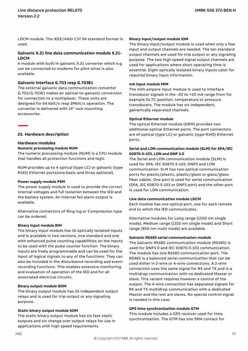
LDCM module. The IEEE/ANSI C37.94 standard format isused.
Galvanic X.21 line data communication module X.21-LDCM
GUID-3C6C7DAC-1DB1-4CB8-991F-3B1D86551F28 v3
A module with built-in galvanic X.21 converter which e.g.can be connected to modems for pilot wires is alsoavailable.
Galvanic interface G.703 resp G.703E1M16035-3 v5
The external galvanic data communication converterG.703/G.703E1 makes an optical-to-galvanic conversionfor connection to a multiplexer. These units aredesigned for 64 kbit/s resp 2Mbit/s operation. Theconverter is delivered with 19” rack mountingaccessories.
23. Hardware description
Hardware modulesIP14529-1 v1
Numeric processing module NUMM12643-3 v4
The numeric processing module (NUM) is a CPU modulethat handles all protection functions and logic.
NUM provides up to 4 optical (type LC) or galvanic (typeRJ45) Ethernet ports(one basic and three optional).
Power supply module PSMM11595-3 v6
The power supply module is used to provide the correctinternal voltages and full isolation between the IED andthe battery system. An internal fail alarm output isavailable.
Alternative connectors of Ring lug or Compression typecan be ordered.
Binary input module BIMM1769-3 v4
The binary input module has 16 optically isolated inputsand is available in two versions, one standard and onewith enhanced pulse counting capabilities on the inputsto be used with the pulse counter function. The binaryinputs are freely programmable and can be used for theinput of logical signals to any of the functions. They canalso be included in the disturbance recording and event-recording functions. This enables extensive monitoringand evaluation of operation of the IED and for allassociated electrical circuits.
Binary output module BOMM6938-3 v4
The binary output module has 24 independent outputrelays and is used for trip output or any signalingpurpose.
Static binary output module SOMSEMOD174196-4 v4
The static binary output module has six fast staticoutputs and six change over output relays for use inapplications with high speed requirements.
Binary input/output module IOMM6939-3 v6
The binary input/output module is used when only a fewinput and output channels are needed. The ten standardoutput channels are used for trip output or any signalingpurpose. The two high speed signal output channels areused for applications where short operating time isessential. Eight optically isolated binary inputs cater forrequired binary input information.
mA input module MIMM15020-3 v4
The milli-ampere input module is used to interfacetransducer signals in the –20 to +20 mA range from forexample OLTC position, temperature or pressuretransducers. The module has six independent,galvanically separated channels.
Optical Ethernet moduleM16073-3 v9
The optical Ethernet module (OEM) provides twoadditional optical Ethernet ports. The port connectorsare of optical (type LC) or galvanic (type RJ45) Ethernetports.
Serial and LON communication module (SLM) for SPA/IEC60870-5-103, LON and DNP 3.0
M14933-3 v6
The Serial and LON communication module (SLM) isused for SPA, IEC 60870-5-103, DNP3 and LONcommunication. SLM has two optical communicationports for plastic/plastic, plastic/glass or glass/glassfiber cables. One port is used for serial communication(SPA, IEC 60870-5-103 or DNP3 port) and the other portis used for LON communication.
Line data communication module LDCMM16075-3 v5
Each module has one optical port, one for each remoteend to which the IED communicates.
Alternative modules for Long range (1550 nm singlemode), Medium range (1310 nm single mode) and Shortrange (850 nm multi mode) are available.
Galvanic RS485 serial communication moduleSEMOD158664-5 v3
The Galvanic RS485 communication module (RS485) isused for DNP3.0 and IEC 60870-5-103 communication.The module has one RS485 communication port. TheRS485 is a balanced serial communication that can beused either in 2-wire or 4-wire connections. A 2-wireconnection uses the same signal for RX and TX and is amultidrop communication with no dedicated Master orslave. This variant requires however a control of theoutput. The 4-wire connection has separated signals forRX and TX multidrop communication with a dedicatedMaster and the rest are slaves. No special control signalis needed in this case.
GPS time synchronization module GTMM14851-3 v5
This module includes a GPS receiver used for timesynchronization. The GTM has one SMA contact for
Line distance protection REL670 1MRK 506 372-BEN HVersion 2.2
ABB 55© Copyright 2017 ABB. All rights reserved

connection to an antenna. It also includes an optical PPSST-connector output.
IRIG-B Time synchronizing moduleSEMOD141113-4 v9
The IRIG-B time synchronizing module is used foraccurate time synchronizing of the IED from a stationclock.
The Pulse Per Second (PPS) input is supported.
Electrical (BNC) and optical connection (ST) for 0XX and12X IRIG-B support.
Transformer input module TRMM14875-3 v9
The transformer input module is used to galvanicallyseparate and adapt the secondary currents and voltagesgenerated by the measuring transformers. The modulehas twelve inputs in different combinations of currentsand voltage inputs.
Alternative connectors of Ring lug or Compression typecan be ordered.
High impedance resistor unitM16727-3 v2
The high impedance resistor unit, with resistors forpick-up value setting and a voltage dependent resistor,is available in a single phase unit and a three phase unit.Both are mounted on a 1/1 19 inch apparatus plate withcompression type terminals.
Layout and dimensionsIP14539-1 v1
DimensionsIP14826-1 v1M15243-4 v7
IEC08000163‐3‐en.vsdx
IEC08000163 V3 EN-US
Figure 15. Case with rear cover
IEC08000165‐3‐en.vsdx
IEC08000165 V3 EN-US
Figure 16. Case with rear cover and 19” rack mounting kit
IEC06000182-2-en.vsdIEC06000182 V2 EN-US
Figure 17. A 1/2 x 19” size IED side-by-side with RHGS6.
M15243-12 v10
Line distance protection REL670 1MRK 506 372-BEN HVersion 2.2
56 ABB© Copyright 2017 ABB. All rights reserved
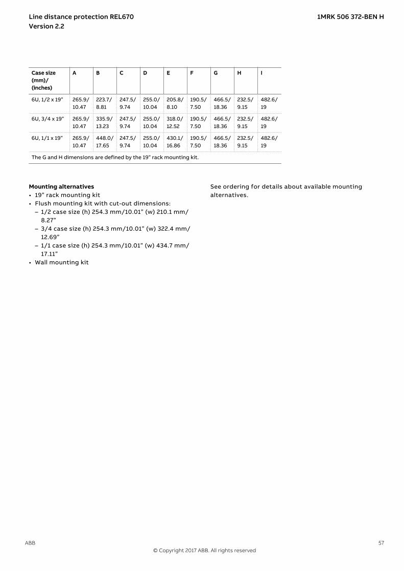
Case size(mm)/(inches)
A B C D E F G H I
6U, 1/2 x 19” 265.9/10.47
223.7/8.81
247.5/9.74
255.0/10.04
205.8/8.10
190.5/7.50
466.5/18.36
232.5/9.15
482.6/19
6U, 3/4 x 19” 265.9/10.47
335.9/13.23
247.5/9.74
255.0/10.04
318.0/12.52
190.5/7.50
466.5/18.36
232.5/9.15
482.6/19
6U, 1/1 x 19” 265.9/10.47
448.0/17.65
247.5/9.74
255.0/10.04
430.1/16.86
190.5/7.50
466.5/18.36
232.5/9.15
482.6/19
The G and H dimensions are defined by the 19” rack mounting kit.
Mounting alternativesM16079-3 v14
• 19” rack mounting kit• Flush mounting kit with cut-out dimensions:
– 1/2 case size (h) 254.3 mm/10.01” (w) 210.1 mm/8.27”
– 3/4 case size (h) 254.3 mm/10.01” (w) 322.4 mm/12.69”
– 1/1 case size (h) 254.3 mm/10.01” (w) 434.7 mm/17.11”
• Wall mounting kit
See ordering for details about available mountingalternatives.
Line distance protection REL670 1MRK 506 372-BEN HVersion 2.2
ABB 57© Copyright 2017 ABB. All rights reserved

24. Connection diagramsGUID-CF4EFFA5-3081-4FC7-9A14-ED127C3C0FDE v7
The connection diagrams are delivered in the IEDConnectivity package as part of the product delivery.
The latest versions of the connection diagrams can bedownloaded fromhttp://www.abb.com/protection-control.
Connection diagrams for IEC Customized products
Connection diagram, 670 series 2.2 1MRK002801-AG
Connection diagrams for Configured products
Connection diagram, REL670 2.2, A41X001MRK002807-LE
Connection diagram, REL670 2.2, A42X001MRK002807-LF
Connection diagram, REL670 2.2, B42X001MRK002807-LG
Connection diagram, REL670 2.2, D42X001MRK002807-LH
Connection diagrams for ANSI Customized products
Connection diagram, 670 series 2.2 1MRK002802-AG
Line distance protection REL670 1MRK 506 372-BEN HVersion 2.2
58 ABB© Copyright 2017 ABB. All rights reserved

25. Technical data
GeneralIP11376-1 v2M10993-1 v3
Definitions
Reference value The specified value of an influencing factor to which are referred the characteristics of the equipment
Nominal range The range of values of an influencing quantity (factor) within which, under specified conditions, the equipment meetsthe specified requirements
Operative range The range of values of a given energizing quantity for which the equipment, under specified conditions, is able toperform its intended functions according to the specified requirements
Presumptions for Technical DataGUID-1E949E38-E04D-4374-A086-912C25E9F93C v2
The technical data stated in this document are only validunder the following circumstances:
1. Main current transformers with 1 A or 2 A secondaryrating are wired to the IED 1 A rated CT inputs.
2. Main current transformer with 5 A secondary ratingare wired to the IED 5 A rated CT inputs.
3. CT and VT ratios in the IED are set in accordance withthe associated main instrument transformers. Notethat for functions which measure an analogue signalwhich do not have corresponding primary quantitythe 1:1 ratio shall be set for the used analogue inputson the IED. Example of such functions are: HZPDIF,ROTIPHIZ and STTIPHIZ.
4. Parameter IBase used by the tested function is setequal to the rated CT primary current.
5. Parameter UBase used by the tested function is setequal to the rated primary phase-to-phase voltage.
6. Parameter SBase used by the tested function is setequal to:– √3 × IBase × UBase
7. The rated secondary quantities have the followingvalues:– Rated secondary phase current Ir is either 1 A or 5 A
depending on selected TRM.– Rated secondary phase-to-phase voltage Ur is
within the range from 100 V to 120 V.– Rated secondary power for three-phase system Sr =
√3 × Ur × Ir
8. For operate and reset time testing, the defaultsetting values of the function are used if not explicitlystated otherwise.
9. During testing, signals with rated frequency havebeen injected if not explicitly stated otherwise.
Line distance protection REL670 1MRK 506 372-BEN HVersion 2.2
ABB 59© Copyright 2017 ABB. All rights reserved

Energizing quantities, rated values and limitsAnalog inputs
IP15842-1 v1M16988-1 v11
Table 11. TRM - Energizing quantities, rated values and limits for protection transformer
Description Value
Frequency
Rated frequency fr 50/60 Hz
Operating range fr ± 10%
Current inputs
Rated current Ir 1 or 5 A
Operating range (0-100) x Ir
Thermal withstand 100 × Ir for 1 s *)30 × Ir for 10 s10 × Ir for 1 min4 × Ir continuously
Dynamic withstand 250 × Ir one half wave
Burden < 20 mVA at Ir = 1 A< 150 mVA at Ir = 5 A
*) max. 350 A for 1 s when COMBITEST test switch is included.
Voltage inputs **)
Rated voltage Ur 110 or 220 V
Operating range 0 - 340 V
Thermal withstand 450 V for 10 s420 V continuously
Burden < 20 mVA at 110 V< 80 mVA at 220 V
**) all values for individual voltage inputs
Note! All current and voltage data are specified as RMS values at rated frequency
Line distance protection REL670 1MRK 506 372-BEN HVersion 2.2
60 ABB© Copyright 2017 ABB. All rights reserved

Table 12. TRM - Energizing quantities, rated values and limits for measuring transformer
Description Value
Frequency
Rated frequency fr 50/60 Hz
Operating range fr ± 10%
Current inputs
Rated current Ir 1A 5 A
Operating range (0-1.8) × Ir (0-1.6) × Ir
Thermal withstand 80 × Ir for 1 s25 × Ir for 10 s10 × Ir for 1 min1.8 × Ir for 30 min1.1 × Ir continuously
65 × Ir for 1 s20 × Ir for 10 s8 × Ir for 1 min1.6 × Ir for 30 min1.1 × Ir continuously
Burden < 200 mVA at Ir < 350 mVA at Ir
Voltage inputs *)
Rated voltage Ur 110 or 220 V
Operating range 0 - 340 V
Thermal withstand 450 V for 10 s420 V continuously
Burden < 20 mVA at 110 V< 80 mVA at 220 V
*) all values for individual voltage inputs
Note! All current and voltage data are specified as RMS values at rated frequency
M6389-1 v5
Table 13. MIM - mA input module
Quantity: Rated value: Nominal range:
Input resistance Rin = 194 Ohm -
Input range ±5, ±10, ±20 mA0-5, 0-10, 0-20, 4-20 mA
-
Power consumptioneach mA boardeach mA input
£ 2 W£ 0.1 W
-
Auxiliary DC voltageIP15843-1 v3M12286-1 v9
Table 14. PSM - Power supply module
Quantity Rated value Nominal range
Auxiliary DC voltage, EL (input) EL = (24-60) VEL = (90-250) V
EL ±20%EL ±20%
Power consumption 50 W typically -
Auxiliary DC power in-rush < 10 A during 0.1 s -
Supply interruption bridging time < 50 ms -
Line distance protection REL670 1MRK 506 372-BEN HVersion 2.2
ABB 61© Copyright 2017 ABB. All rights reserved

Binary inputs and outputsIP15844-1 v1M12576-1 v12
Table 15. BIM - Binary input module
Quantity Rated value Nominal range
Binary inputs 16 -
DC voltage, RL 24/30 V48/60 V110/125 V220/250 V
RL ±20%RL ±20%RL ±20%RL ±20%
Power consumption24/30 V, 50 mA48/60 V, 50 mA110/125 V, 50 mA220/250 V, 50 mA220/250 V, 110 mA
max. 0.05 W/inputmax. 0.1 W/inputmax. 0.2 W/inputmax. 0.4 W/inputmax. 0.5 W/input
-
Counter input frequency 10 pulses/s max -
Oscillating signal discriminator Blocking settable 1–40 HzRelease settable 1–30 Hz
*Debounce filter Settable 1–20 ms
Binary input operate time(Debounce filter set to 0 ms)
3 ms -
* Note: For compliance with surge immunity a debounce filter time setting of 5 ms is required.
Maximum 176 binary input channelsmay be activated simultaneously withinfluencing factors within nominalrange.
The stated operate time for functionsinclude the operating time for thebinary inputs and outputs.
M50609-2 v9
Table 16. BIM - Binary input module with enhanced pulse counting capabilities
Quantity Rated value Nominal range
Binary inputs 16 -
DC voltage, RL 24/30 V48/60 V110/125 V220/250 V
RL ±20%RL ±20%RL ±20%RL ±20%
Power consumption24/30 V48/60 V110/125 V220/250 V
max. 0.05 W/inputmax. 0.1 W/inputmax. 0.2 W/inputmax. 0.4 W/input
-
Counter input frequency 10 pulses/s max -
Balanced counter input frequency 40 pulses/s max -
Oscillating signal discriminator Blocking settable 1–40 HzRelease settable 1–30 Hz
*Debounce filter Settable 1-20 ms
Binary input operate time(Debounce filter set to 0 ms)
3 ms -
* Note: For compliance with surge immunity a debounce filter time setting of 5 ms is required.
Line distance protection REL670 1MRK 506 372-BEN HVersion 2.2
62 ABB© Copyright 2017 ABB. All rights reserved

Maximum 176 binary input channelsmay be activated simultaneously withinfluencing factors within nominalrange.
The stated operate time for functionsinclude the operating time for thebinary inputs and outputs.
M12573-1 v11
Table 17. IOM - Binary input/output module
Quantity Rated value Nominal range
Binary inputs 8 -
DC voltage, RL 24/30 V48/60 V110/125 V220/250 V
RL ±20%RL ±20%RL ±20%RL ±20%
Power consumption24/30 V, 50 mA48/60 V, 50 mA110/125 V, 50 mA220/250 V, 50 mA220/250 V, 110 mA
max. 0.05 W/inputmax. 0.1 W/inputmax. 0.2 W/inputmax. 0.4 W/inputmax. 0.5 W/input
-
Counter input frequency 10 pulses/s max
Oscillating signal discriminator Blocking settable 1-40 HzRelease settable 1-30 Hz
*Debounce filter Settable 1-20 ms
Binary input operate time(Debounce filter set to 0 ms)
3 ms -
* Note: For compliance with surge immunity a debounce filter time setting of 5 ms is required.
Line distance protection REL670 1MRK 506 372-BEN HVersion 2.2
ABB 63© Copyright 2017 ABB. All rights reserved

Maximum 176 binary input channelsmay be activated simultaneously withinfluencing factors within nominalrange.
The stated operate time for functionsinclude the operating time for thebinary inputs and outputs.
M12318-1 v10
Table 18. IOM - Binary input/output module contact data (reference standard: IEC 61810-2)
Function or quantity Trip and signal relays Fast signal relays (parallelreed relay)
Binary outputs 10 2
Max system voltage 250 V AC, DC 250 V DC
Min load voltage 24VDC —
Test voltage across open contact, 1 min 1000 V rms 800 V DC
Current carrying capacityPer relay, continuousPer relay, 1 sPer process connector pin, continuous
8 A10 A12 A
8 A10 A12 A
Making capacity at inductive load with L/R > 10 ms 0.2 s1.0 s
30 A10 A
0.4 A0.4 A
Making capacity at resistive load 0.2 s1.0 s
30 A10 A
220–250 V/0.4 A110–125 V/0.4 A48–60 V/0.2 A24–30 V/0.1 A
Breaking capacity for AC, cos φ > 0.4 250 V/8.0 A 250 V/8.0 A
Breaking capacity for DC with L/R < 40 ms 48 V/1 A110 V/0.4 A125 V/0.35 A220 V/0.2 A250 V/0.15 A
48 V/1 A110 V/0.4 A125 V/0.35 A220 V/0.2 A250 V/0.15 A
Maximum capacitive load - 10 nF
Max operations with load 1000
Max operations with no load 10000
Operating time < 6 ms <= 1 ms
Line distance protection REL670 1MRK 506 372-BEN HVersion 2.2
64 ABB© Copyright 2017 ABB. All rights reserved

Maximum 72 outputs may be activatedsimultaneously with influencing factorswithin nominal range. After 6 ms anadditional 24 outputs may beactivated. The activation time for the96 outputs must not exceed 200 ms. 48outputs can be activated during 1 s.Continued activation is possible withrespect to current consumption butafter 5 minutes the temperature risewill adversely affect the hardware life.Maximum two relays perBOM/IOM/SOM should be activatedcontinuously due to power dissipation.
The stated operate time for functionsinclude the operating time for thebinary inputs and outputs.
M12584-1 v10
Table 19. IOM with MOV and IOM 220/250 V, 110mA - contact data (reference standard: IEC 61810-2)
Function or quantity Trip and Signal relays Fast signal relays (parallel reed relay)
Binary outputs IOM: 10 IOM: 2
Max system voltage 250 V AC, DC 250 V DC
Min load voltage 24VDC -
Test voltage across opencontact, 1 min
250 V rms 250 V rms
Current carrying capacityPer relay, continuousPer relay, 1 sPer process connector pin,continuous
8 A10 A12 A
8 A10 A12 A
Making capacity at inductiveloadwith L/R > 10 ms0.2 s1.0 s
30 A10 A
0.4 A0.4 A
Making capacity at resistiveload 0.2 s1.0 s
30 A10 A
220–250 V/0.4 A110–125 V/0.4 A48–60 V/0.2 A24–30 V/0.1 A
Breaking capacity for AC, cos j> 0.4
250 V/8.0 A 250 V/8.0 A
Breaking capacity for DC withL/R < 40 ms
48 V/1 A110 V/0.4 A220 V/0.2 A250 V/0.15 A
48 V/1 A110 V/0.4 A220 V/0.2 A250 V/0.15 A
Maximum capacitive load - 10 nF
Max operations with load 1000 -
Max operations with no load 10000 -
Operating time < 6 ms <= 1 ms
Line distance protection REL670 1MRK 506 372-BEN HVersion 2.2
ABB 65© Copyright 2017 ABB. All rights reserved

Maximum 72 outputs may be activatedsimultaneously with influencing factorswithin nominal range. After 6 ms anadditional 24 outputs may beactivated. The activation time for the96 outputs must not exceed 200 ms. 48outputs can be activated during 1 s.Continued activation is possible withrespect to current consumption butafter 5 minutes the temperature risewill adversely affect the hardware life.Maximum two relays perBOM/IOM/SOM should be activatedcontinuously due to power dissipation.
The stated operate time for functionsinclude the operating time for thebinary inputs and outputs.
SEMOD175395-2 v9
Table 20. SOM - Static Output Module (reference standard: IEC 61810-2): Static binary outputs
Function of quantity Static binary output trip
Rated voltage 48-60 VDC 110-250 VDC
Number of outputs 6 6
Impedance open state ~300 kΩ ~810 kΩ
Test voltage across open contact, 1 min No galvanic separation No galvanic separation
Current carrying capacity:
Continuous 5 A 5 A
1.0 s 10 A 10 A
Making capacity at capacitive load with themaximum capacitance of 0.2 μF :
0.2 s 30 A 30 A
1.0 s 10 A 10 A
Breaking capacity for DC with L/R ≤ 40 ms 48 V/1 A 110 V/0.4 A
60 V/0.75 A 125 V/0.35 A
220 V/0.2 A
250 V/0.15 A
Operating time < 1 ms < 1 ms
Line distance protection REL670 1MRK 506 372-BEN HVersion 2.2
66 ABB© Copyright 2017 ABB. All rights reserved

Table 21. SOM - Static Output module data (reference standard: IEC 61810-2): Electromechanical relay outputs
Function of quantity Trip and signal relays
Max system voltage 250 V AC/DC
Min load voltage 24VDC
Number of outputs 6
Test voltage across open contact, 1 min 1000 V rms
Current carrying capacity:
Continuous 8 A
1.0 s 10 A
Max operations with load 1000
Max operations with no load 10000
Making capacity at capacitive load with the maximum capacitanceof 0.2 μF:
0.2 s 30 A
1.0 s 10 A
Breaking capacity for DC with L/R ≤ 40 ms 48 V/1 A
110 V/0.4 A
125 V/0.35 A
220 V/0.2 A
250 V/0.15 A
Operating time < 6 ms
Line distance protection REL670 1MRK 506 372-BEN HVersion 2.2
ABB 67© Copyright 2017 ABB. All rights reserved

The stated operate time for functionsinclude the operating time for thebinary inputs and outputs.
M12441-1 v10
Table 22. BOM - Binary output module contact data (reference standard: IEC 61810-2)
Function or quantity Trip and Signal relays
Binary outputs 24
Max system voltage 250 V AC, DC
Min load voltage 24VDC
Test voltage across open contact, 1 min 1000 V rms
Current carrying capacityPer relay, continuousPer relay, 1 sPer process connector pin, continuous
8 A10 A12 A
Max operations with load 1000
Max operations with no load 10000
Making capacity at inductive load with L/R > 10 ms0.2 s1.0 s
30 A10 A
Breaking capacity for AC, cos j > 0.4 250 V/8.0 A
Breaking capacity for DC with L/R < 40 ms 48 V/1 A110 V/0.4 A125 V/0.35 A220 V/0.2 A250 V/0.15 A
Operating time < 6 ms
The stated operate time for functionsinclude the operating time for thebinary inputs and outputs.
Influencing factorsIP15846-1 v1M16705-1 v16
Table 23. Temperature and humidity influence
Parameter Reference value Nominal range Influence
Ambient temperature, operatevalue
+20±5°C -25°C to +55°C 0.02%/°C
Relative humidityOperative range
45-75%0-95%
10-90% -
Storage temperature - -40°C to +70°C -
Line distance protection REL670 1MRK 506 372-BEN HVersion 2.2
68 ABB© Copyright 2017 ABB. All rights reserved

Table 24. Auxiliary DC supply voltage influence on functionality during operation
Dependence on Reference value Within nominalrange
Influence
Ripple, in DC auxiliary voltageOperative range
max. 2%Full waverectified
15% of EL 0.01%/%
Auxiliary voltage dependence,operate value
±20% of EL 0.01%/%
Interrupted auxiliary DC voltage
24-60 V DC ± 20% 100-250 V DC ±20%
Interruptioninterval0–50 ms
No restart
0–∞ s Correct behaviour at power down
Restart time < 300 s
Table 25. Frequency influence (reference standard: IEC 60255–1)
Dependence on Within nominal range Influence
Frequency dependence, operate value fr ±2.5 Hz for 50 Hzfr ±3.0 Hz for 60 Hz
±1.0%/Hz
Frequency dependence for distance protection operate value fr ±2.5 Hz for 50 Hzfr ±3.0 Hz for 60 Hz
±2.0%/Hz
Harmonic frequency dependence (20% content) 2nd, 3rd and 5th harmonic of fr ±2.0%
Harmonic frequency dependence for distance protection (10%content)
2nd, 3rd and 5th harmonic of fr ±10.0%
Harmonic frequency dependence for high impedance differentialprotection (10% content)
2nd, 3rd and 5th harmonic of fr ±10.0%
Harmonic frequency dependence for overcurrent protection 2nd, 3rd and 5th harmonic of fr ±3.0%
Type tests according to standardsIP15778-1 v1M16706-1 v14
Line distance protection REL670 1MRK 506 372-BEN HVersion 2.2
ABB 69© Copyright 2017 ABB. All rights reserved

Table 26. Electromagnetic compatibility
Test Type test values Reference standards
1 MHz burst disturbance 2.5 kV IEC 60255-26
100 kHz slow damped oscillatory wave immunity test 2.5 kV IEC 61000-4-18, Level 3
Ring wave immunity test, 100 kHz 2-4 kV IEC 61000-4-12, Level 4
Electrostatic dischargeDirect applicationIndirect application
15 kV air discharge8 kV contact discharge8 kV contact discharge
IEC 60255-26 IEC 61000-4-2, Level 4
Electrostatic dischargeDirect applicationIndirect application
15 kV air discharge8 kV contact discharge8 kV contact discharge
IEEE/ANSI C37.90.3
Fast transient disturbance 4 kV2 kV, SFP galvanic RJ452 kV, MIM mA-inputs
IEC 60255-26, Zone A IEC 60255-26, Zone B
Surge immunity test 2-4 kV, 1.2/50ms high energy1-2 kV, BOM and IRF outputs
IEC 60255-26, Zone AIEC 60255-26, Zone B
Power frequency immunity test 150-300 V, 50 Hz IEC 60255-26, Zone A
Conducted common mode immunity test 30-3 V, 15-150 Hz IEC 61000-4-16, Level 4
Power frequency magnetic field test 1000 A/m, 3 s100 A/m, cont.
IEC 61000-4-8, Level 5
Pulse magnetic field immunity test 1000 A/m IEC 61000–4–9, Level 5
Damped oscillatory magnetic field test 100 A/m IEC 61000-4-10, Level 5
Radiated electromagnetic field disturbance 20 V/m80-1000 MHz1.4-2.7 GHz10 V/m, 2.7-6.0 GHz
IEC 60255-26IEEE/ANSI C37.90.2EN 50121-5
Radiated emission 30-6000 MHz IEC 60255-26
30-8500 MHz IEEE/ANSI C63.4, FCC
Conducted emission 0.15-30 MHz IEC 60255-26
Table 27. Insulation
Test Type test values Reference standard
Dielectric test 2.0 kV AC, 1 min.1.0 kV AC, 1 min.:-SFP galvanic RJ45- X.21-LDCM
IEC 60255-27ANSI C37.90IEEE 802.3-2015,Environment A
Impulse voltage test 5 kV, 1.2/50ms, 0.5 J1 kV, 1.2/50 ms 0.5 J:-SFP galvanic RJ45- X.21-LDCM
Insulation resistance > 100 MW at 500 VDC
Line distance protection REL670 1MRK 506 372-BEN HVersion 2.2
70 ABB© Copyright 2017 ABB. All rights reserved
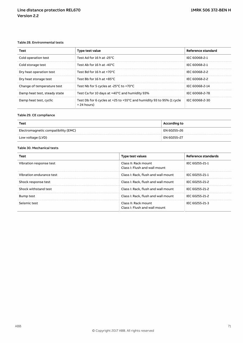
Table 28. Environmental tests
Test Type test value Reference standard
Cold operation test Test Ad for 16 h at -25°C IEC 60068-2-1
Cold storage test Test Ab for 16 h at -40°C IEC 60068-2-1
Dry heat operation test Test Bd for 16 h at +70°C IEC 60068-2-2
Dry heat storage test Test Bb for 16 h at +85°C IEC 60068-2-2
Change of temperature test Test Nb for 5 cycles at -25°C to +70°C IEC 60068-2-14
Damp heat test, steady state Test Ca for 10 days at +40°C and humidity 93% IEC 60068-2-78
Damp heat test, cyclic Test Db for 6 cycles at +25 to +55°C and humidity 93 to 95% (1 cycle= 24 hours)
IEC 60068-2-30
Table 29. CE compliance
Test According to
Electromagnetic compatibility (EMC) EN 60255–26
Low voltage (LVD) EN 60255–27
Table 30. Mechanical tests
Test Type test values Reference standards
Vibration response test Class II: Rack mountClass I: Flush and wall mount
IEC 60255-21-1
Vibration endurance test Class I: Rack, flush and wall mount IEC 60255-21-1
Shock response test Class I: Rack, flush and wall mount IEC 60255-21-2
Shock withstand test Class I: Rack, flush and wall mount IEC 60255-21-2
Bump test Class I: Rack, flush and wall mount IEC 60255-21-2
Seismic test Class II: Rack mountClass I: Flush and wall mount
IEC 60255-21-3
Line distance protection REL670 1MRK 506 372-BEN HVersion 2.2
ABB 71© Copyright 2017 ABB. All rights reserved

Differential protectionM13081-1 v12
Table 31. High impedance differential protection, single phase HZPDIF
Function Range or value Accuracy
Operate voltage (10-900) VI=U/R
±1.0% of Ir at I ≤ Ir±1.0% of I at I > Ir
Reset ratio >95% at (30-900) V -
Maximum continuous power U>Trip2/SeriesResistor ≤200 W -
Operate time at 0 to 10 x Ud Min. = 5 msMax. = 15 ms
Reset time at 10 x Ud to 0 Min. = 75 msMax. = 95 ms
Critical impulse time 2 ms typically at 0 to 10 x Ud -
Operate time at 0 to 2 x Ud Min. = 25 msMax. = 35 ms
Reset time at 2 x Ud to 0 Min. = 50 msMax. = 70 ms
Critical impulse time 15 ms typically at 0 to 2 x Ud -
GUID-0BD8D3C9-620A-426C-BDB5-DAA0E4F8247F v4
Table 32. Additional security logic for differential protection LDRGFC
Function Range or value Accuracy
Operate current, zero sequence current (1-100)% of lBase ±1.0% of Ir
Operate current, low current operation (1-100)% of lBase ±1.0% of Ir
Operate voltage, phase to neutral (1-100)% of UBase ±0.5% of Ur
Operate voltage, phase to phase (1-100)% of UBase ±0.5% of Ur
Independent time delay, zero sequence current at 0 to 2 x Iset (0.000-60.000) s ±0.2% or ±40 mswhichever is greater
Independent time delay, low current operation at 2 x Iset to 0 (0.000-60.000) s ±0.2% or ± 40 mswhichever is greater
Independent time delay, low voltage operation at 2 x Uset to 0 (0.000-60.000) s ±0.2% or ±40 mswhichever is greater
Reset time delay for startup signal at 0 to 2 x Uset (0.000-60.000) s ±0.2% or ±40 mswhichever is greater
Line distance protection REL670 1MRK 506 372-BEN HVersion 2.2
72 ABB© Copyright 2017 ABB. All rights reserved

Impedance protectionM13842-1 v15
Table 33. Distance measuring zone, Quad ZMQPDIS
Function Range or value Accuracy
Number of zones Max 5 with selectabledirection
-
Minimum operate residualcurrent, zone 1
(5-1000)% of IBase -
Minimum operate current,phase-to-phase and phase-to-earth
(10-1000)% of IBase -
Positive sequence reactance (0.10-3000.00) Ω/phase ±2.0% static accuracy±2.0 degrees static angular accuracyConditions:Voltage range: (0.1-1.1) x Ur
Current range: (0.5-30) x IrAngle: at 0 degrees and 85 degrees
Positive sequence resistance (0.01-1000.00) Ω/phase
Zero sequence reactance (0.10-9000.00) Ω/phase
Zero sequence resistance (0.01-3000.00) Ω/phase
Fault resistance, phase-to-earth
(0.10-9000.00) Ω/loop
Fault resistance, phase-to-phase
(0.10-3000.00) Ω/loop
Dynamic overreach <5% at 85 degreesmeasured with CVT’sand 0.5<SIR<30
-
Definite time delay Ph-Ph andPh-E operation
(0.000-60.000) s ±0.2% or ±40 ms whichever is greater
Operate time 25 ms typically IEC 60255-121
Reset ratio 105% typically -
Reset time at 0.1 x Zreach to 2x Zreach
Min. = 20 msMax. = 50 ms
-
Line distance protection REL670 1MRK 506 372-BEN HVersion 2.2
ABB 73© Copyright 2017 ABB. All rights reserved

SEMOD173239-2 v10
Table 34. Distance measuring zone, quadrilateral characteristic for series compensated lines ZMCPDIS, ZMCAPDIS
Function Range or value Accuracy
Number of zones Max 5 with selectable direction -
Minimum operate residualcurrent, zone 1
(5-1000)% of IBase -
Minimum operate current, Ph-Ph and Ph-E
(10-1000)% of IBase -
Positive sequence reactance (0.10-3000.00) Ω/phase ±2.0% static accuracy±2.0 degrees static angular accuracyConditions:Voltage range: (0.1-1.1) x Ur
Current range: (0.5-30) x IrAngle: at 0 degrees and 85 degrees
Positive sequence resistance (0.10-1000.00) Ω/phase
Zero sequence reactance (0.01-9000.00) Ω/phase
Zero sequence resistance (0.01-3000.00) Ω/phase
Fault resistance, Ph-E (0.10-9000.00) Ω/loop
Fault resistance, Ph-Ph (0.10-3000.00) Ω/loop
Dynamic overreach <5% at 85 degrees measuredwith CCVT’s and 0.5<SIR<30
-
Definite time delay Ph-Ph andPh-E operation
(0.000-60.000) s ±0.2% or ± 35 ms whichever is greater
Operate time 25 ms typically IEC 60255-121
Reset ratio 105% typically -
Reset time at 0.1 x Zreach to 2x Zreach
Min. = 20 msMax. = 50 ms
-
M16024-1 v12
Table 35. Phase selection, quadrilateral characteristic with fixed angle FDPSPDIS
Function Range or value Accuracy
Minimum operate current (5-500)% of IBase ±1.0% of Ir at I ≤ Ir±1.0% of I at I > Ir
Reactive reach, positivesequence
(0.50–3000.00) Ω/phase ±2.5% static accuracy±2.0 degrees static angular accuracyConditions:Voltage range: (0.1-1.1) x Ur
Current range: (0.5-30) x IrAngle: at 0 degrees and 85 degrees
Resistive reach, positivesequence
(0.10–1000.00) Ω/phase
Reactive reach, zero sequence (0.50–9000.00) Ω/phase
Resistive reach, zero sequence (0.50–3000.00) Ω/phase
Fault resistance, phase-to-earth faults, forward andreverse
(1.00–9000.00) Ω/loop
Fault resistance, phase-to-phase faults, forward andreverse
(0.50–3000.00) Ω/loop
Load encroachment criteria:Load resistance, forward andreverseSafety load impedance angle
(1.00–3000.00) Ω/phase(5-70) degrees
Reset ratio 105% typically -
Line distance protection REL670 1MRK 506 372-BEN HVersion 2.2
74 ABB© Copyright 2017 ABB. All rights reserved

SEMOD173242-2 v14
Table 36. Full-scheme distance protection, Mho characteristic ZMHPDIS
Function Range or value Accuracy
Number of zones, Ph-E Max 5 with selectabledirection
-
Minimum operate current (10–30)% of IBase -
Positive sequence impedance,Ph-E loop
(0.005–3000.000) W/phase ±2.0% static accuracyConditions:Voltage range: (0.1-1.1) x Ur
Current range: (0.5-30) x IrAngle: 85 degrees
Positive sequence impedanceangle, Ph-E loop
(10–90) degrees
Reverse reach, Ph-E loop(Magnitude)
(0.005–3000.000) Ω/phase
Magnitude of earth returncompensation factor KN
(0.00–3.00)
Angle for earth compensationfactor KN
(-180–180) degrees
Dynamic overreach <5% at 85 degreesmeasured with CVT’s and0.5<SIR<30
-
Definite time delay Ph-Ph andPh-E operation
(0.000-60.000) s ±0.2% or ±60 ms whichever is greater
Operate time 22 ms typically IEC 60255-121
Reset ratio 105% typically -
Reset time at 0.5 x Zreach to1.5 x Zreach
Min. = 30 msMax. = 50 ms
-
SEMOD173249-2 v8
Table 37. Full-scheme distance protection, quadrilateral for earth faults ZMMPDIS
Function Range or value Accuracy
Number of zones Max 5 with selectable direction -
Minimum operate current (10-30)% of IBase -
Positive sequence reactance (0.50-3000.00) W/phase ±2.0% static accuracy±2.0 degrees static angular accuracyConditions:Voltage range: (0.1-1.1) x Ur
Current range: (0.5-30) x IrAngle: at 0 degrees and 85 degrees
Positive sequence resistance (0.10-1000.00) Ω/phase
Zero sequence reactance (0.50-9000.00) Ω/phase
Zero sequence resistance (0.50-3000.00) Ω/phase
Fault resistance, Ph-E (1.00-9000.00) W/loop
Dynamic overreach <5% at 85 degrees measuredwith CCVT’s and 0.5<SIR<30
-
Definite time delay Ph-Ph andPh-E operation
(0.000-60.000) s ±0.2% or ±40 ms whichever is greater
Operate time 25 ms typically IEC 60255-121
Reset ratio 105% typically -
Reset time at 0.1 x Zreach to 2x Zreach
Min. = 20 msMax. = 50 ms
-
Line distance protection REL670 1MRK 506 372-BEN HVersion 2.2
ABB 75© Copyright 2017 ABB. All rights reserved

SEMOD153649-2 v8
Table 38. Faulty phase identification with load encroachment FMPSPDIS
Function Range or value Accuracy
Load encroachment criteria:Load resistance, forward andreverse
(1.00–3000.00) W/phase(5–70) degrees
±2.0% static accuracyConditions:Voltage range: (0.1–1.1) x Ur
Current range: (0.5–30) x IrAngle: at 0 degrees and 85 degrees
GUID-7617A215-AE7C-47CC-B189-4914F530F717 v7
Table 39. Distance measuring zone, quadrilateral characteristic, separate settings ZMRPDIS, ZMRAPDIS
Function Range or value Accuracy
Number of zones Max 5 withselectable direction
-
Minimum operate residualcurrent, zone 1
(5-1000)% of IBase -
Minimum operate current,phase-to-phase and phase-to-earth
(10-1000)% of IBase -
Positive sequence reactance (0.10-3000.00) Ω/phase
±2.0% static accuracy±2.0 degrees static angular accuracyConditions:Voltage range: (0.1-1.1) x Ur
Current range: (0.5-30) x IrAngle: at 0 degrees and 85 degrees
Positive sequence resistance (0.01-1000.00) Ω/phase
Zero sequence reactance (0.10-9000.00) Ω/phase
Zero sequence resistance (0.01-3000.00) Ω/phase
Fault resistance, phase-to-earth
(0.10-9000.00) Ω/loop
Fault resistance, phase-to-phase
(0.10-3000.00) Ω/loop
Dynamic overreach <5% at 85 degreesmeasured with CVT’sand 0.5<SIR<30
-
Definite time delay phase-phase and phase-earthoperation
(0.000-60.000) s ±0.2% or ±40 ms whichever is greater
Operate time 25 ms typically IEC 60255-121
Reset ratio 105% typically -
Reset time at 0.1 x Zreach to 2x Zreach
Min. = 20 msMax. =50 ms
-
Line distance protection REL670 1MRK 506 372-BEN HVersion 2.2
76 ABB© Copyright 2017 ABB. All rights reserved

GUID-9E13C38A-3B6D-402B-98A6-6CDA20632CE7 v5
Table 40. Phase selection, quadrilateral characteristic with settable angle FRPSPDIS
Function Range or value Accuracy
Minimum operate current (5-500)% of IBase ±1.0% of Ir at I ≤ Ir±1.0% of I at I > Ir
Reactive reach, positivesequence
(0.50–3000.00) Ω/phase ±2.0% static accuracy±2.0 degrees static angular accuracyConditions:Voltage range: (0.1-1.1) x Ur
Current range: (0.5-30) x IrAngle: at 0 degrees and 85 degrees
Resistive reach, positivesequence
(0.10–1000.00) Ω/phase
Reactive reach, zero sequence (0.50–9000.00) Ω/phase
Resistive reach, zero sequence (0.50–3000.00) Ω/phase
Fault resistance, Ph-E faults,forward and reverse
(1.00–9000.00) Ω/loop
Fault resistance, Ph-Ph faults,forward and reverse
(0.50–3000.00) Ω/loop
Reset ratio 105% typically -
Line distance protection REL670 1MRK 506 372-BEN HVersion 2.2
ABB 77© Copyright 2017 ABB. All rights reserved

GUID-6C2EF52A-8166-4A23-9861-38931682AA7D v7
Table 41. High speed distance protection ZMFPDIS, ZMFCPDIS
Function Range or value Accuracy
Number of zones 3 selectabledirections, 3 fixeddirections
-
Minimum operate current, Ph-Ph and Ph-E
(5-6000)% of IBase ±1.0% of Ir
Positive sequence reactancereach, Ph-E and Ph-Ph loop
(0.01 - 3000.00)ohm/p
Pseudo continuous ramp:±2.0% of set valueConditions:Voltage range: (0.1-1.1) x Ur
Current range: (0.5-30) x IrAngle: At 0 degrees and 85 degreesIEC 60255-121 points A,B,C,D,E
Ramp of shots:±2.0% of set valueConditions:IEC 60255-121 point B
Positive sequence resistancereach, Ph-E and Ph-Ph loop
(0.00 - 1000.00)ohm/p
Zero sequence reactance reach (0.01 - 9000.00)ohm/p
Zero sequence resistive reach (0.00 - 3000.00)ohm/p
Fault resistance reach, Ph-Eand Ph-Ph
(0.01 -9000.00)ohm/l
Dynamic overreach < 5% at 85 degreesmeasured with CVTsand 0.5 < SIR < 30,IEC 60255-121
-
Reset ratio 105% typically -
Directional blinders Forward: -15 – 120degreesReverse: 165 – -60degrees
Pseudo continuous ramp:±2.0 degrees, IEC 60255-121
Resistance determining theload impedance area - forward
(0.01 - 5000.00)ohm/p
Pseudo continuous ramp:±2.0% of set valueConditions:Tested at ArgLd = 30 degrees
Ramp of shots:±5.0% of set valueConditions:Tested at ArgLd = 30 degrees
Angle determining the loadimpedance area
5 - 70 degrees Pseudo continuous ramp:±2.0 degreesConditions:Tested at RLdFw = 20 ohm/p
Definite time delay to trip, Ph-Eand Ph-Ph operation
(0.000-60.000) s ±0.2% of set value or ±35 ms whichever is greater
Operate time 16 ms typically, IEC60255-121
-
Reset time at 0.1 to 2 x Zreach Min. = 20 msMax. = 35 ms
-
Line distance protection REL670 1MRK 506 372-BEN HVersion 2.2
78 ABB© Copyright 2017 ABB. All rights reserved

M16036-1 v10
Table 42. Power swing detection ZMRPSB
Function Range or value Accuracy
Reactive reach (0.10-3000.00) W/phase
±2.0% static accuracyConditions:Voltage range: (0.1-1.1) x Ur
Current range: (0.5-30) x IrAngle: at 0 degrees and 85 degreesResistive reach (0.10–1000.00) W/loop
Power swing detectionoperate time
(0.000-60.000) s ±0.2% or ±10 ms whichever is greater
Second swing reclaim operatetime
(0.000-60.000) s ±0.2% or ±20 ms whichever is greater
Minimum operate current (5-30)% of IBase ±1.0% of Ir
SEMOD171935-5 v5
Table 43. Power swing logic PSLPSCH
Function Range or value Accuracy
Permitted maximumoperating time differencebetween higher and lowerzone
(0.000 — 60.0000) s ±0,2% or ±15 ms whichever is greater
Delay for operation ofunderreach zone withdetected difference inoperating time
(0.000 — 60.0000) s ±0,2% or ±15 ms whichever is greater
Conditional timer forsending the CS at powerswings
(0.000 — 60.0000) s ±0,2% or ±15 ms whichever is greater
Conditional timer fortripping at power swings
(0.000 — 60.0000) s ±0,2% or ±15 ms whichever is greater
Timer for blocking theoverreaching zones trip
(0.000 — 60.0000) s ±0,2% or ±15 ms whichever is greater
GUID-88E02516-1BFE-4075-BEEB-027484814697 v2
Table 44. Pole slip protection PSPPPAM
Function Range or value Accuracy
Impedance reach (0.00 - 1000.00)% of Zbase ±2.0% of Ur/Ir
Zone 1 and Zone 2 tripcounters
(1 - 20) -
SEMOD175136-2 v8
Table 45. Out-of-step protection OOSPPAM
Function Range or value Accuracy
Impedance reach (0.00 - 1000.00)% of Zbase ±2.0% of Ur/(√3 ⋅ Ir)
Rotor start angle (90.0 - 130.0) degrees ±5.0 degrees
Rotor trip angle (15.0 - 90.0) degrees ±5.0 degrees
Zone 1 and Zone 2 tripcounters
(1 - 20) -
Line distance protection REL670 1MRK 506 372-BEN HVersion 2.2
ABB 79© Copyright 2017 ABB. All rights reserved

GUID-BACA37F7-E945-40BC-BF9D-A65BFC96CA91 v8
Table 46. Phase preference logic PPLPHIZ
Function Range or value Accuracy
Operate value, phase-to-phaseand phase-to-neutralundervoltage
(1 - 100)% of UBase ±0.5% of Ur
Reset ratio, undervoltage < 105% -
Operate value, residual voltage (5 - 300)% of UBase ±0.5% of Ur at U ≤ Ur
±0.5% of U at U > Ur
Reset ratio, residual voltage > 95% -
Operate value, residual current (10 - 200)% of IBase ±1.0% of Ir at I ≤ Ir±1.0% of I at I > Ir
Reset ratio, residual current > 95% -
Independent time delay forresidual current at 0 to 2 x Iset
(0.000 - 60.000) s ±0.2% or ±25 ms whichever is greater
Independent time delay forresidual voltage at 0.8 x Uset to1.2 x Uset
(0.000 - 60.000) s ±0.2% or ±25 ms whichever is greater
Independent dropoff-delay forresidual voltage at 1.2 x Uset to0.8 x Uset
(0.000 - 60.000) s ±0.2% or ±25 ms whichever is greater
Operating mode No Filter, NoPrefCyclic: 1231c, 1321cAcyclic: 123a, 132a, 213a, 231a, 312a, 321a
Line distance protection REL670 1MRK 506 372-BEN HVersion 2.2
80 ABB© Copyright 2017 ABB. All rights reserved

GUID-42119BFF-1756-431C-A5A1-0AB637213E96 v1
Table 47. Phase preference logic PPL2PHIZ
Function Range or value Accuracy
Operate value, phase-to-phaseand phase-to-neutralundervoltage
(1 - 100)% of UBase ±0.5% of Ur
Reset ratio, undervoltage < 105% -
Operate value, residual voltage (5 - 300)% of UBase ±0.5% of Ur at U ≤ Ur
±0.5% of U at U > Ur
Reset ratio, residual voltage > 95% -
Operate value, residual current (10 - 200)% of IBase ±1.0% of Ir at I ≤ Ir±1.0% of I at I > Ir
Reset ratio, residual current > 95% -
Independent time delay forresidual current at 0 to 2 x Iset
(0.000 - 60.000) s ±0.2% or ±25 ms whichever is greater
Independent time delay forresidual voltage at 0.8 to 1.2 xUset
(0.000 - 60.000) s ±0.2% or ±25 ms whichever is greater
Independent dropoff-delay forresidual voltage at 1.2 to 0.8 xUset
(0.000 - 60.000) s ±0.2% or ±25 ms whichever is greater
Operating mode No Filter, NoPrefCyclic: 1231c, 1321cAcyclic: 123a, 132a, 213a, 231a, 312a, 321a
M16043-1 v12
Table 48. Automatic switch onto fault logic ZCVPSOF
Parameter Range or value Accuracy
Operate voltage, detection of dead line (1–100)% ofUBase
±0.5% of Ur
Operate current, detection of dead line (1–100)% ofIBase
±1.0% of Ir
Time delay to operate for the switch onto faultfunction
(0.03-120.00) s ±0.2% or ±20 ms whichever is greater
Time delay for UI detection (0.000-60.000) s ±0.2% or ±20 ms whichever is greater
Delay time for activation of dead line detection (0.000-60.000) s ±0.2% or ±20 ms whichever is greater
Drop-off delay time of switch onto fault function (0.000-60.000) s ±0.2% or ±30 ms whichever is greater
Line distance protection REL670 1MRK 506 372-BEN HVersion 2.2
ABB 81© Copyright 2017 ABB. All rights reserved

Wide area measurement systemGUID-F0BAEBD8-E361-4D50-9737-7DF8B043D66A v4
Table 49. Protocol reporting via IEEE 1344 and C37.118 PMUREPORT
Influencing quantity Range Accuracy
Signal frequency ± 0.1 x fr ≤ 1.0% TVE
Signal magnitude:Voltage phasorCurrent phasor
(0.1–1.2) x Ur
(0.5–2.0) x Ir
Phase angle ± 180°
Harmonic distortion 10% from 2nd – 50th
Interfering signal:MagnitudeMinimum frequencyMaximum frequency
10% of fundamental signal0.1 x fr
1000 Hz
Line distance protection REL670 1MRK 506 372-BEN HVersion 2.2
82 ABB© Copyright 2017 ABB. All rights reserved

Current protectionM12336-1 v13
Table 50. Instantaneous phase overcurrent protection PHPIOC
Function Range or value Accuracy
Operate current (5-2500)% of lBase ±1.0% of Ir at I ≤ Ir±1.0% of I at I > Ir
Reset ratio > 95% at (50–2500)% of IBase -
Operate time at 0 to 2 x Iset Min. = 15 msMax. = 25 ms
-
Reset time at 2 x Iset to 0 Min. = 15 msMax. = 25 ms
-
Critical impulse time 10 ms typically at 0 to 2 x Iset -
Operate time at 0 to 10 x Iset Min. = 5 msMax. = 15 ms
-
Reset time at 10 x Iset to 0 Min. = 25 msMax. = 40 ms
-
Critical impulse time 2 ms typically at 0 to 10 x Iset -
Dynamic overreach < 5% at t = 100 ms -
Line distance protection REL670 1MRK 506 372-BEN HVersion 2.2
ABB 83© Copyright 2017 ABB. All rights reserved

M12342-1 v21
Table 51. Directional phase overcurrent protection, four steps OC4PTOC
Function Range or value Accuracy
Operate current, step 1-4 (5-2500)% of lBase ±1.0% of Ir at I ≤ Ir±1.0% of I at I > Ir
Reset ratio > 95% at (50–2500)% oflBase
-
Minimum operate current, step 1-4 (1-10000)% of lBase ±1.0% of Ir at I ≤ Ir±1.0% of I at I > Ir
Relay characteristic angle (RCA) (40.0–65.0) degrees ±2.0 degrees
Relay operating angle (ROA) (40.0–89.0) degrees ±2.0 degrees
Second harmonic blocking (5–100)% of fundamental ±2.0% of Ir
Independent time delay at 0 to 2 x Iset, step1-4
(0.000-60.000) s ±0.2% or ±35 ms whichever is greater
Minimum operate time for inverse curves ,step 1-4
(0.000-60.000) s ±0.2% or ±35 ms whichever is greater
Inverse time characteristics, see table 187,table 188 and table 189
16 curve types See table 187, table 188 and table 189
Operate time, start non-directional at 0 to2 x Iset
Min. = 15 ms -
Max. = 30 ms
Reset time, start non-directional at 2 x Iset
to 0Min. = 15 ms -
Max. = 30 ms
Operate time, start non-directional at 0 to10 x Iset
Min. = 5 msMax. = 20 ms
-
Reset time, start non-directional at 10 x Iset
to 0Min. = 20 msMax. = 35 ms
-
Critical impulse time 10 ms typically at 0 to 2 x Iset -
Impulse margin time 15 ms typically -
Operate frequency, directional overcurrent 38-83 Hz -
Operate frequency, non-directionalovercurrent
10-90 Hz -
Line distance protection REL670 1MRK 506 372-BEN HVersion 2.2
84 ABB© Copyright 2017 ABB. All rights reserved

M12340-2 v9
Table 52. Instantaneous residual overcurrent protection EFPIOC
Function Range or value Accuracy
Operate current (5-2500)% of lBase ±1.0% of Ir at I ≤ Ir±1.0% of I at I > Ir
Reset ratio > 95% at (50–2500)% of lBase -
Operate time at 0 to 2 x Iset Min. = 15 msMax. = 25 ms
-
Reset time at 2 x Iset to 0 Min. = 15 msMax. = 25 ms
-
Critical impulse time 10 ms typically at 0 to 2 x Iset -
Operate time at 0 to 10 xIset
Min. = 5 msMax. = 15 ms
-
Reset time at 10 x Iset to 0 Min. = 25 msMax. = 35 ms
-
Critical impulse time 2 ms typically at 0 to 10 x Iset -
Dynamic overreach < 5% at t = 100 ms -
Line distance protection REL670 1MRK 506 372-BEN HVersion 2.2
ABB 85© Copyright 2017 ABB. All rights reserved

M15223-1 v18
Table 53. Directional residual overcurrent protection, four steps EF4PTOC
Function Range or value Accuracy
Operate current, step 1-4 (1-2500)% of IBase ±1.0% of Ir at I ≤ Ir±1.0% of I at I > Ir
Reset ratio > 95% at (10-2500)% ofIBase
-
Relay characteristic angle(RCA)
(-180 to 180) degrees ±2.0 degrees
Operate current for directional release (1–100)% of IBase For RCA ±60 degrees:±2.5% of Ir at I ≤ Ir±2.5% of I at I > Ir
Independent time delay at 0 to 2 x Iset,step 1-4
(0.000-60.000) s ±0.2% or ±35 ms whichever is greater
Minimum operate time for inverse curves,step 1-4
(0.000 - 60.000) s ±0.2% or ±35 ms whichever is greater
Inverse time characteristics, see Table 187,Table 188 and Table 189
16 curve types See Table 187, Table 188 and Table 189
Second harmonic blocking (5–100)% of fundamental ±2.0% of Ir
Minimum polarizing voltage (1–100)% of UBase ±0.5% of Ur
Minimum polarizing current (2-100)% of IBase ±1.0% of Ir
Real part of source Z used for currentpolarization
(0.50-1000.00) W/phase -
Imaginary part of source Z used forcurrent polarization
(0.50–3000.00) W/phase -
*Operate time, start non-directional at 0to 2 x Iset
Min. = 15 msMax. = 30 ms
-
*Reset time, start non-directional at 2 x Iset
to 0Min. = 15 msMax. = 30 ms
-
*Operate time, start non-directional at 0to 10 x Iset
Min. = 5 msMax. = 20 ms
-
*Reset time, start non-directional at 10 xIset to 0
Min. = 20 msMax. = 35 ms
-
Critical impulse time 10 ms typically at 0 to 2 x Iset -
Impulse margin time 15 ms typically -
*Note: Operate time and reset time are only valid if harmonic blocking is turned off for a step.
Line distance protection REL670 1MRK 506 372-BEN HVersion 2.2
86 ABB© Copyright 2017 ABB. All rights reserved

GUID-E83AD807-8FE0-4244-A50E-86B9AF92469E v6
Table 54. Four step directional negative phase sequence overcurrent protection NS4PTOC
Function Range or value Accuracy
Operate current, step 1 - 4 (1-2500)% of lBase ±1.0% of Ir at I £ Ir±1.0% of I at I > Ir
Reset ratio > 95% at (10-2500)% ofIBase
-
Independent time delay at 0 to 2 x Iset,step 1 - 4
(0.000-60.000) s ±0.2% or ±35 ms whichever is greater
Minimum operate time for inversecurves, step 1 - 4
(0.000 - 60.000) s ±0.2% or ±35 ms whichever is greater
Inverse time characteristics, see table187, table 188 and table 189
16 curve types See table 187, table 188 and table 189
Minimum operate current, step 1 - 4 (1.00 - 10000.00)% of IBase ±1.0% of Ir at I ≤ Ir±1.0% of I at I > Ir
Relay characteristic angle (RCA) (-180 to 180) degrees ±2.0 degrees
Operate current for directional release (1–100)% of IBase For RCA ±60 degrees:±2.5% of Ir at I ≤ Ir±2.5% of I at I > Ir
Minimum polarizing voltage (1–100)% of UBase ±0.5% of Ur
Real part of negative sequence sourceimpedance used for currentpolarization
(0.50-1000.00) W/phase -
Imaginary part of negative sequencesource impedance used for currentpolarization
(0.50–3000.00) W/phase -
Operate time, start non-directional at 0to 2 x Iset
Min. = 15 msMax. = 30 ms
-
Reset time, start non-directional at 2 xIset to 0
Min. = 15 msMax. = 30 ms
-
Operate time, start non-directional at 0to 10 x Iset
Min. = 5 msMax. = 20 ms
-
Reset time, start non-directional at 10 xIset to 0
Min. = 20 msMax. = 35 ms
-
Critical impulse time 10 ms typically at 0 to 2 x Iset -
Impulse margin time 15 ms typically -
Transient overreach <10% at τ = 100 ms -
Line distance protection REL670 1MRK 506 372-BEN HVersion 2.2
ABB 87© Copyright 2017 ABB. All rights reserved

SEMOD173350-2 v16
Table 55. Sensitive directional residual overcurrent and power protection SDEPSDE
Function Range or value Accuracy
Operate level for 3I0·cosj directionalresidual overcurrent
(0.25-200.00)% of IBase ±1.0% of Ir at I £ Ir±1.0% of I at I > Ir
Operate level for ·3I0·3U0 cosj directionalresidual power
(0.25-200.00)% of SBase ±1.0% of Sr at S £ Sr
±1.0% of S at S > Sr
Operate level for 3I0 and j residualovercurrent
(0.25-200.00)% of IBase ±1.0% of Ir at £ Ir±1.0% of I at I > Ir
Operate level for non-directionalovercurrent
(1.00-400.00)% of IBase ±1.0% of Ir at I £ Ir±1.0% of I at I > Ir
Operate level for non-directional residualovervoltage
(1.00-200.00)% of UBase ±0.5% of Ur at U £ Ur
±0.5% of U at U > Ur
Residual release current for all directionalmodes
(0.25-200.00)% of IBase ±1.0% of Ir at I £ Ir±1.0% of I at I > Ir
Residual release voltage for all directionalmodes
(1.00-300.00)% of UBase ±0.5% of Ur at U £ Ur
±0.5% of U at U > Ur
Operate time for non-directional residualovercurrent at 0 to 2 x Iset
Min. = 40 ms
Max. = 65 ms
Reset time for non-directional residualovercurrent at 2 x Iset to 0
Min. = 40 ms
Max. = 65 ms
Operate time for directional residualovercurrent at 0 to 2 x Iset
Min. = 110 ms
Max. = 160 ms
Reset time for directional residualovercurrent at 2 x Iset to 0
Min. = 20 ms
Max. = 60 ms
Independent time delay for non-directional residual overvoltage at 0.8 xUset to 1.2 x Uset
(0.000 – 60.000) s ±0.2% or ± 75 ms whichever is greater
Independent time delay for non-directional residual overcurrent at 0 to 2 xIset
(0.000 – 60.000) s ±0.2% or ± 75 ms whichever is greater
Independent time delay for directionalresidual overcurrent at 0 to 2 x Iset
(0.000 – 60.000) s ±0.2% or ± 170 ms whichever is greater
Inverse characteristics, see table 190,Table 191 and Table 192
16 curve types See Table 190, Table 191 and Table 192
Relay characteristic angle (RCADir) (-179 to 180) degrees ±2.0 degrees
Relay operate angle (ROADir) (0 to 90) degrees ±2.0 degrees
Line distance protection REL670 1MRK 506 372-BEN HVersion 2.2
88 ABB© Copyright 2017 ABB. All rights reserved

M12352-1 v15
Table 56. Thermal overload protection, one time constant LCPTTR/LFPTTR
Function Range or value Accuracy
Reference current (2-400)% of IBase ±1.0% of Ir
Reference temperature (0-300)°C, (0 - 600)°F ±1.0°C, ±2.0°F
Operate time:
2 2
2 2
ln p
Trip Amb
ref
ref
I It
T TI I
T
σ,
<,
, √
EQUATION13000039 V3 EN-US (Equation 1)
TTrip= set operate temperatureTAmb = ambient temperatureTref = temperature rise above ambient at Iref
Iref = reference load currentI = actual measured currentIp = load current before overload occurs
Time constant t = (1–1000)minutes
IEC 60255-149, ±5.0% or ±200 ms whichever is greater
Alarm temperature (0-200)°C, (0-400)°F ±2.0°C, ±4.0°F
Operate temperature (0-300)°C, (0-600)°F ±2.0°C, ±4.0°F
Reset level temperature (0-300)°C, (0-600)°F ±2.0°C, ±4.0°F
M12353-1 v15
Table 57. Breaker failure protection CCRBRF
Function Range or value Accuracy
Operate phase current (5-200)% of lBase ±1.0% of Ir at I £ Ir±1.0% of I at I > Ir
Reset ratio, phase current > 95% -
Operate residual current (2-200)% of lBase ±1.0% of Ir at I £ Ir±1.0% of I at I > Ir
Reset ratio, residual current > 95% -
Phase current level for blocking of contactfunction
(5-200)% of lBase ±1.0% of Ir at I £ Ir±1.0% of I at I > Ir
Reset ratio > 95% -
Operate time for current detection 10 ms typically -
Reset time for current detection 10 ms maximum * -
Time delay for retrip at 0 to 2 x Iset (0.000-60.000) s ±0.2% or ±15 ms whichever is greater
Time delay for backup trip at 0 to 2 x Iset (0.000-60.000) s ±0.2% or ±15 ms whichever is greater
Time delay for backup trip at multi-phase startat 0 to 2 x Iset
(0.000-60.000) s ±0.2% or ±20 ms whichever is greater
Additional time delay for a second backup tripat 0 to 2 x Iset
(0.000-60.000) s ±0.2% or ±20 ms whichever is greater
Time delay for alarm for faulty circuit breaker (0.000-60.000) s ±0.2% or ±15 ms whichever is greater
Minimum trip pulse duration (0.010-60.000) s ±0.2% or ±5 ms whichever is greater
* Valid for product version 2.2.3 or later
Line distance protection REL670 1MRK 506 372-BEN HVersion 2.2
ABB 89© Copyright 2017 ABB. All rights reserved

M12350-1 v12
Table 58. Stub protection STBPTOC
Function Range or value Accuracy
Operating current (5-2500)% of IBase ±1.0% of Ir at I ≤ Ir±1.0% of I at I > Ir
Reset ratio > 95% at (50-2500)% of IBase -
Independent time delay at 0 to 2 x Iset (0.000-60.000) s ±0.2% or ±30 ms whichever is greater
Operate time, start at 0 to 2 x Iset Min. = 10 msMax. = 20 ms
-
Reset time, start at 2 x Iset to 0 Min. = 10 msMax. = 20 ms
-
Critical impulse time 10 ms typically at 0 to 2 x Iset -
Impulse margin time 15 ms typically -
M13279-1 v10
Table 59. Pole discordance protection CCPDSC
Function Range or value Accuracy
Operate current (0–100)% of IBase ±1.0% of Ir
Independent time delaybetween trip condition andtrip signal
(0.000-60.000) s ±0.2% or ± 30 ms whichever is greater
SEMOD175152-2 v11
Table 60. Directional underpower protection GUPPDUP
Function Range or value Accuracy
Power levelfor Step 1 and Step 2
(0.0–500.0)% of SBase ±1.0% of Sr at S ≤ Sr
±1.0% of S at S > Sr
where
1.732r r rS U I= × ×
Characteristic anglefor Step 1 and Step 2
(-180.0–180.0) degrees ±2.0 degrees
Independent time delay to operate forStep 1 and Step 2 at 2 x Sr to 0.5 x Sr andk=0.000
(0.01-6000.00) s ±0.2% or ±40 ms whichever is greater
Line distance protection REL670 1MRK 506 372-BEN HVersion 2.2
90 ABB© Copyright 2017 ABB. All rights reserved

SEMOD175159-2 v9
Table 61. Directional overpower protection GOPPDOP
Function Range or value Accuracy
Power levelfor Step 1 and Step 2
(0.0–500.0)% of SBase
±1.0% of Sr at S ≤ Sr
±1.0% of S at S > Sr
Characteristic anglefor Step 1 and Step 2
(-180.0–180.0) degrees ±2.0 degrees
Operate time, start at 0.5 x Sr to 2 x Sr andk=0.000
Min. =10 ms
Max. = 25 ms
Reset time, start at 2 x Sr to 0.5 x Sr andk=0.000
Min. = 35 ms
Max. = 55 ms
Independent time delay to operate forStep 1 and Step 2 at 0.5 x Sr to 2 x Sr andk=0.000
(0.01-6000.00) s ±0.2% or ±40 ms whichever is greater
SEMOD175200-2 v7
Table 62. Broken conductor check BRCPTOC
Function Range or value Accuracy
Minimum phase current for operation (5–100)% of IBase ±1.0% of Ir
Unbalance current operation (50–90)% of maximum current ±1.0% of Ir
Independent operate time delay (0.000-60.000) s ±0.2% or ±45 ms whichever is greater
Independent reset time delay (0.010-60.000) s ±0.2% or ±30 ms whichever is greater
Start time at current change from Ir to 0 Min. = 25 msMax. = 35 ms
-
Reset time at current change from 0 toIr
Min. = 5 msMax. = 20 ms
-
Line distance protection REL670 1MRK 506 372-BEN HVersion 2.2
ABB 91© Copyright 2017 ABB. All rights reserved

GUID-7EA9731A-8D56-4689-9072-D72D9CDFD795 v8
Table 63. Voltage-restrained time overcurrent protection VRPVOC
Function Range or value Accuracy
Start overcurrent (2.0 - 5000.0)% of IBase ±1.0% of Ir at I ≤ Ir±1.0% of I at I > Ir
Reset ratio, overcurrent > 95% -
Operate time, start overcurrent at 0 to 2 xIset
Min. = 15 ms -
Max. = 30 ms
Reset time, start overcurrent at 2 x Iset to 0 Min. = 15 ms -
Max. = 30 ms
Operate time, start overcurrent at 0 to 10x Iset
Min. = 5 msMax. = 20 ms
-
Reset time, start overcurrent at 10 x Iset to0
Min. = 20 msMax. = 35 ms
-
Independent time delay to operate at 0 to2 x Iset
(0.00 - 6000.00) s ±0.2% or ±35 ms whichever is greater
Inverse time characteristics,see tables 187 and 188
13 curve types See tables 187 and 188
Minimum operate time for inverse timecharacteristics
(0.00 - 60.00) s ±0.2% or ±35 ms whichever is greater
High voltage limit, voltage dependentoperation
(30.0 - 100.0)% of UBase ±1.0% of Ur
Start undervoltage (2.0 - 100.0)% of UBase ±0.5% of Ur
Reset ratio, undervoltage < 105% -
Operate time start undervoltage at 2 x Uset
to 0Min. = 15 ms -
Max. = 30 ms
Reset time start undervoltage at 0 to 2 xUset
Min. = 15 ms -
Max. = 30 ms
Independent time delay to operate,undervoltage at 2 x Uset to 0
(0.00 - 6000.00) s ±0.2% or ±35 ms whichever is greater
Internal low voltage blocking (0.0 - 5.0)% of UBase ±0.25% of Ur
Overcurrent:Critical impulse timeImpulse margin time
10 ms typically at 0 to 2 x Iset
15 ms typically
-
Undervoltage:Critical impulse timeImpulse margin time
10ms typically at 2 x Uset to 015 ms typically
-
Line distance protection REL670 1MRK 506 372-BEN HVersion 2.2
92 ABB© Copyright 2017 ABB. All rights reserved

Voltage protectionM13290-1 v15
Table 64. Two step undervoltage protection UV2PTUV
Function Range or value Accuracy
Operate voltage, low and high step (1.0–100.0)% of UBase ±0.5% of Ur
Absolute hysteresis (0.0–50.0)% of UBase ±0.5% of Ur
Internal blocking level, step 1 and step2
(1–50)% of UBase ±0.5% of Ur
Inverse time characteristics for step 1and step 2, see table 196
- See table 196
Definite time delay, step 1 at 1.2 x Uset
to 0(0.00-6000.00) s ±0.2% or ±40ms whichever is greater
Definite time delay, step 2 at 1.2 x Uset
to 0(0.000-60.000) s ±0.2% or ±40ms whichever is greater
Minimum operate time, inversecharacteristics
(0.000–60.000) s ±0.5% or ±40ms whichever is greater
Operate time, start at 2 x Uset to 0 Min. = 15 msMax. = 30 ms
-
Reset time, start at 0 to 2 x Uset Min. = 15 msMax. = 30 ms
-
Operate time, start at 1.2 x Uset to 0 Min. = 5 msMax. = 25 ms
-
Reset time, start at 0 to 1.2 x Uset Min. = 15 msMax. = 35 ms
-
Critical impulse time 5 ms typically at 1.2 x Uset to 0 -
Impulse margin time 15 ms typically -
Line distance protection REL670 1MRK 506 372-BEN HVersion 2.2
ABB 93© Copyright 2017 ABB. All rights reserved

M13304-1 v14
Table 65. Two step overvoltage protection OV2PTOV
Function Range or value Accuracy
Operate voltage, step 1 and 2 (1.0-200.0)% of UBase ±0.5% of Ur at U ≤ Ur
±0.5% of U at U > Ur
Absolute hysteresis (0.0–50.0)% of UBase ±0.5% of Ur at U ≤ Ur
±0.5% of U at U > Ur
Inverse time characteristics for steps 1and 2, see table 195
- See table 195
Definite time delay, low step (step 1) at0 to 1.2 x Uset
(0.00 - 6000.00) s ±0.2% or ±45 ms whichever is greater
Definite time delay, high step (step 2) at0 to 1.2 x Uset
(0.000-60.000) s ±0.2% or ±45 ms whichever is greater
Minimum operate time, Inversecharacteristics
(0.000-60.000) s ±0.2% or ±45 ms whichever is greater
Operate time, start at 0 to 2 x Uset Min. = 15 msMax. = 30 ms
-
Reset time, start at 2 x Uset to 0 Min. = 15 msMax. = 30 ms
-
Operate time, start at 0 to 1.2 x Uset Min. = 20 msMax. = 35 ms
-
Reset time, start at 1.2 x Uset to 0 Min. = 5 msMax. = 25 ms
-
Critical impulse time 10 ms typically at 0 to 2 xUset
-
Impulse margin time 15 ms typically -
Line distance protection REL670 1MRK 506 372-BEN HVersion 2.2
94 ABB© Copyright 2017 ABB. All rights reserved

M13317-2 v14
Table 66. Two step residual overvoltage protection ROV2PTOV
Function Range or value Accuracy
Operate voltage, step 1 - step 2 (1.0-200.0)% of UBase ± 0.5% of Ur at U ≤ Ur
± 0.5% of U at U > Ur
Absolute hysteresis (0.0–50.0)% of UBase ± 0.5% of Ur at U ≤ Ur
± 0.5% of U at U > Ur
Inverse time characteristics for lowand high step, see table 197
- See table 197
Definite time delay low step (step 1) at0 to 1.2 x Uset
(0.00–6000.00) s ± 0.2% or ± 45 ms whichever is greater
Definite time delay high step (step 2)at 0 to 1.2 x Uset
(0.000–60.000) s ± 0.2% or ± 45 ms whichever is greater
Minimum operate time (0.000-60.000) s ± 0.2% or ± 45 ms whichever is greater
Operate time, start at 0 to 2 x Uset Min. = 15 msMax. = 30 ms
-
Reset time, start at 2 x Uset to 0 Min. = 15 msMax. = 30 ms
-
Operate time, start at 0 to 1.2 x Uset Min. = 20 msMax. = 35 ms
-
Reset time, start at 1.2 x Uset to 0 Min. = 5 msMax. = 25 ms
-
Critical impulse time 10 ms typically at 0 to 2 x Uset -
Impulse margin time 15 ms typically -
M13338-2 v11
Table 67. Overexcitation protection OEXPVPH
Function Range or value Accuracy
Operate value, start (100–180)% of (UBase/frated) ±0.5% of U
Operate value, alarm (50–120)% of start level ±0.5% of Ur at U ≤ Ur
±0.5% of U at U > Ur
Operate value, high level (100–200)% of (UBase/frated) ±0.5% of U
Curve type IEEE or customer defined
2
(0.18 ):
( 1)k
IEEE tM
×=
-
EQUATION1319 V1 EN-US (Equation 2)
where M = (E/f)/(Ur/fr)
±5.0 % or ±45 ms, whichever is greater
Minimum time delay for inversefunction
(0.000–60.000) s ±1.0% or ±45 ms, whichever is greater
Maximum time delay for inversefunction
(0.00–9000.00) s ±1.0% or ±45 ms, whichever is greater
Alarm time delay (0.00–9000.00) ±1.0% or ±45 ms, whichever is greater
Line distance protection REL670 1MRK 506 372-BEN HVersion 2.2
ABB 95© Copyright 2017 ABB. All rights reserved

SEMOD166919-2 v7
Table 68. Voltage differential protection VDCPTOV
Function Range or value Accuracy
Voltage difference for alarm and trip (2.0–100.0) % of UBase ±0.5% of Ur
Under voltage level (1.0–100.0) % of UBase ±0.5% of Ur
Independent time delay for voltagedifferential alarm at 0.8 x UDAlarm to 1.2 xUDAlarm
(0.000–60.000)s ±0.2% or ±40 ms whichever is greater
Independent time delay for voltagedifferential trip at 0.8 x UDTrip to 1.2 xUDTrip
(0.000–60.000)s ±0.2% or ±40 ms whichever is greater
Independent time delay for voltagedifferential reset at 1.2 x UDTrip to 0.8 xUDTrip
(0.000–60.000)s ±0.2% or ±40 ms whichever is greater
SEMOD175210-2 v6
Table 69. Loss of voltage check LOVPTUV
Function Range or value Accuracy
Operate voltage (1–100)% of UBase ±0.5% of Ur
Pulse timer whendisconnecting all three phases
(0.050–60.000) s ±0.2% or ±15 ms whichever is greater
Time delay for enabling thefunctions after restoration
(0.000–60.000) s ±0.2% or ±35 ms whichever is greater
Operate time delay whendisconnecting all three phases
(0.000–60.000) s ±0.2% or ±35 ms whichever is greater
Time delay to block when allthree phase voltages are notlow
(0.000–60.000) s ±0.2% or ±35 ms whichever is greater
GUID-C172D5EB-51E8-4FC9-B2E7-EF976872FD7E v6
Table 70. Radial feeder protection PAPGAPC
Function Range or value Accuracy
Residual current detection (10 - 150)% of IBase ±1.0% of Ir at I ≤ Ir±1.0% of I at I > Ir
Reset ratio >95% at (50 - 150)% of IBase -
Operate time, residual current detection at0 to 2 x Iset
Min. = 15 ms -
Max. = 30 ms
Independent time delay to operate, residualcurrent detection at 0 to 2 x Iset
(0.000 - 60.000) s ±0.2% or ±40 ms whichever is greater
Voltage based phase selection (30 - 100)% of UBase ±1.0% of Ur
Reset ratio <115% -
Operate time, voltage-based phaseselection at 1.2 x Uset to 0.8 x Uset
Min. = 15 ms -
Max. = 30 ms
Independent time delay to operate, voltage-based phase selection at 1.2 x Uset to 0.8 xUset
(0.000 – 60.000) s ±0.2% or ±40 ms whichever is greater
Line distance protection REL670 1MRK 506 372-BEN HVersion 2.2
96 ABB© Copyright 2017 ABB. All rights reserved

Frequency protectionM13360-1 v15
Table 71. Underfrequency protection SAPTUF
Function Range or value Accuracy
Operate value, start function, at symmetricalthree phase voltage
(35.00-75.00) Hz ±2.0 mHz
Operate time, start at fset + 0.02 Hz to fset - 0.02Hz fn = 50 Hz
Min. = 80 ms
-Max. = 95 ms
fn = 60 HzMin. = 65 ms
Max. = 80 ms
Reset time, start at fset - 0.02 Hz to fset + 0.02 Hz Min. = 15 msMax. = 30 ms
-
Operate time, definite time function at fset +0.02 Hz to fset - 0.02 Hz
(0.000-60.000)s ±0.2% or ±100 ms whichever is greater
Reset time, definite time function at fset - 0.02Hz to fset + 0.02 Hz
(0.000-60.000)s ±0.2% or ±120 ms whichever is greater
Voltage dependent time delay Settings:UNom=(50-150)% of Ubase
UMin=(50-150)% of Ubase
Exponent=0.0-5.0tMax=(0.010–60.000)stMin=(0.010–60.000)s
±1.0% or ±100 ms whichever is greater
( )ExponentU UMin
t tMax tMin tMinUNom UMin
-= × - +
-é ùê úë û
EQUATION1182 V1 EN-US (Equation 3)
U=Umeasured
M14964-1 v12
Table 72. Overfrequency protection SAPTOF
Function Range or value Accuracy
Operate value, start function at symmetrical three-phase voltage (35.00-90.00) Hz ±2.0 mHz
Operate time, start at fset -0.02 Hz to fset +0.02 Hzfn = 50Hz
Min. = 80 msMax. = 95 ms
-
fn = 60 HzMin. = 65 msMax. = 80 ms
Reset time, start at fset +0.02 Hz to fset -0.02 Hz Min. = 15 msMax. = 30 ms
-
Operate time, definite time function at fset -0.02 Hz to fset +0.02 Hz (0.000-60.000)s ±0.2% ±100 mswhichever is greater
Reset time, definite time function at fset +0.02 Hz to fset -0.02 Hz (0.000-60.000)s ±0.2% ±120 ms,whichever is greater
Line distance protection REL670 1MRK 506 372-BEN HVersion 2.2
ABB 97© Copyright 2017 ABB. All rights reserved

M14976-1 v10
Table 73. Rate-of-change of frequency protection SAPFRC
Function Range or value Accuracy
Operate value, start function (-10.00-10.00) Hz/s ±10.0 mHz/s
Operate value, restore enable frequency (45.00-65.00) Hz ±2.0 mHz
Definite restore time delay (0.000-60.000) s ±0.2% or ±100 ms whichever isgreater
Definite time delay for frequency gradient trip (0.000-60.000) s ±0.2% or ±120 ms whichever isgreater
Definite reset time delay (0.000-60.000) s ±0.2% or ±250 ms whichever isgreater
Line distance protection REL670 1MRK 506 372-BEN HVersion 2.2
98 ABB© Copyright 2017 ABB. All rights reserved

Multipurpose protectionM13095-2 v11
Table 74. General current and voltage protection CVGAPC
Function Range or value Accuracy
Measuring current input phase1, phase2, phase3, PosSeq, -NegSeq, -3*ZeroSeq, MaxPh,MinPh, UnbalancePh, phase1-phase2, phase2-phase3, phase3-phase1, MaxPh-Ph, MinPh-Ph,UnbalancePh-Ph
-
Measuring voltage input phase1, phase2, phase3, PosSeq, -NegSeq, -3*ZeroSeq, MaxPh,MinPh, UnbalancePh, phase1-phase2, phase2-phase3, phase3-phase1, MaxPh-Ph, MinPh-Ph,UnbalancePh-Ph
-
Start overcurrent, step 1 - 2 (2 - 5000)% of IBase ±1.0% of Ir at I ≤ Ir±1.0% of I at I > Ir
Start undercurrent, step 1 - 2 (2 - 150)% of IBase ±1.0% of Ir at I ≤ Ir±1.0% of I at I > Ir
Independent time delay, overcurrent at0 to 2 x Iset, step 1 - 2
(0.00 - 6000.00) s ±0.2% or ±35 ms whichever is greater
Independent time delay, undercurrentat 2 x Iset to 0, step 1 - 2
(0.00 - 6000.00) s ±0.2% or ±35 ms whichever is greater
Overcurrent (non-directional):
Start time at 0 to 2 x Iset Min. = 15 msMax. = 30 ms
-
Reset time at 2 x Iset to 0 Min. = 15 msMax. = 30 ms
-
Start time at 0 to 10 x Iset Min. = 5 msMax. = 20 ms
-
Reset time at 10 x Iset to 0 Min. = 20 msMax. = 35 ms
-
Undercurrent:
Start time at 2 x Iset to 0 Min. = 15 msMax. = 30 ms
-
Reset time at 0 to 2 x Iset Min. = 15 msMax. = 30 ms
-
Overcurrent:
Inverse time characteristics, see table187, 188 and table 189
16 curve types See table 187, 188 and table 189
Overcurrent:
Minimum operate time for inversecurves, step 1 - 2
(0.00 - 6000.00) s ±0.2% or ±35 ms whichever is greater
Voltage level where voltage memorytakes over
(0.0 - 5.0)% of UBase ±0.5% of Ur
Start overvoltage, step 1 - 2 (2.0 - 200.0)% of UBase ±0.5% of Ur at U ≤ Ur
±0.5% of U at U > Ur
Line distance protection REL670 1MRK 506 372-BEN HVersion 2.2
ABB 99© Copyright 2017 ABB. All rights reserved

Table 74. General current and voltage protection CVGAPC, continued
Function Range or value Accuracy
Start undervoltage, step 1 - 2 (2.0 - 150.0)% of UBase ±0.5% of Ur at U ≤ Ur
±0.5% of U at U > Ur
Independent time delay, overvoltage at0.8 x Uset to 1.2 x Uset, step 1 - 2
(0.00 - 6000.00) s ±0.2% or ±35 ms whichever is greater
Independent time delay, undervoltageat 1.2 x Uset to 0.8 x Uset, step 1 - 2
(0.00 - 6000.00) s ±0.2% or ±35 ms whichever is greater
Overvoltage:
Start time at 0.8 x Uset to 1.2 x Uset Min. = 15 msMax. = 30 ms
-
Reset time at 1.2 x Uset to 0.8 x Uset Min. = 15 msMax. = 30 ms
-
Undervoltage:
Start time at 1.2 x Uset to 0.8 x Uset Min. = 15 msMax. = 30 ms
-
Reset time at 1.2 x Uset to 0.8 x Uset Min. = 15 msMax. = 30 ms
-
Overvoltage:
Inverse time characteristics, see table195
4 curve types See table 195
Undervoltage:
Inverse time characteristics, see table196
3 curve types See table 196
High and low voltage limit, voltagedependent operation, step 1 - 2
(1.0 - 200.0)% of UBase ±1.0% of Ur at U ≤ Ur
±1.0% of U at U > Ur
Directional function Settable: NonDir, forward andreverse
-
Relay characteristic angle (-180 to +180) degrees ±2.0 degrees
Relay operate angle (1 to 90) degrees ±2.0 degrees
Reset ratio, overcurrent > 95% -
Reset ratio, undercurrent < 105% -
Reset ratio, overvoltage > 95% -
Reset ratio, undervoltage < 105% -
Operate frequency 10-90 Hz -
Overcurrent:
Critical impulse time 10 ms typically at 0 to 2 x Iset -
Impulse margin time 15 ms typically -
Undercurrent:
Critical impulse time 10 ms typically at 2 x Iset to 0 -
Impulse margin time 15 ms typically -
Overvoltage:
Critical impulse time 10 ms typically at 0.8 x Uset to 1.2 xUset
-
Line distance protection REL670 1MRK 506 372-BEN HVersion 2.2
100 ABB© Copyright 2017 ABB. All rights reserved

Table 74. General current and voltage protection CVGAPC, continued
Function Range or value Accuracy
Impulse margin time 15 ms typically -
Undervoltage:
Critical impulse time 10 ms typically at 1.2 x Uset to 0.8 xUset
-
Impulse margin time 15 ms typically -
Line distance protection REL670 1MRK 506 372-BEN HVersion 2.2
ABB 101© Copyright 2017 ABB. All rights reserved

Secondary system supervisionM12358-1 v10
Table 75. Current circuit supervision CCSSPVC
Function Range or value Accuracy
Operate current (10-200)% of IBase ±10.0% of Ir at I ≤ Ir±10.0% of I at I > Ir
Reset ratio, Operate current >90%
Block current (20-500)% of IBase ±5.0% of Ir at I ≤ Ir±5.0% of I at I > Ir
Reset ratio, Block current >90% at (50-500)% of IBase
M16069-1 v12
Table 76. Fuse failure supervision FUFSPVC
Function Range or value Accuracy
Operate voltage, zero sequence (1-100)% of UBase ±0.5% of Ur
Operate current, zero sequence (1–100)% of IBase ±0.5% of Ir
Operate voltage, negative sequence (1-100)% of UBase ±0.5% of Ur
Operate current, negative sequence (1–100)% of IBase ±0.5% of Ir
Operate voltage change level (1-100)% of UBase ±10.0% of Ur
Operate current change level (1–100)% of IBase ±10.0% of Ir
Operate phase voltage (1-100)% of UBase ±0.5% of Ur
Operate phase current (1–100)% of IBase ±0.5% of Ir
Operate phase dead line voltage (1-100)% of UBase ±0.5% of Ur
Operate phase dead line current (1–100)% of IBase ±0.5% of Ir
Operate time, start, 1 ph, at 1 x Ur to 0 Min. = 10 msMax. = 25 ms
-
Reset time, start, 1 ph, at 0 to 1 x Ur Min. = 15 msMax. = 30 ms
-
Line distance protection REL670 1MRK 506 372-BEN HVersion 2.2
102 ABB© Copyright 2017 ABB. All rights reserved

GUID-E2EA8017-BB4B-48B0-BEDA-E71FEE353774 v5
Table 77. Fuse failure supervision VDSPVC
Function Range or value Accuracy
Operate value, block of main fuse failure (10.0-80.0)% of UBase ±0.5% of Ur
Reset ratio <110%
Operate time, block of main fuse failure at 1 x Ur
to 0Min. = 5 ms –
Max. = 15 ms
Reset time, block of main fuse failure at 0 to 1 x Ur Min. = 15 ms –
Max. = 30 ms
Operate value, alarm for pilot fuse failure (10.0-80.0)% of UBase ±0.5% of Ur
Reset ratio <110% –
Operate time, alarm for pilot fuse failure at 1 x Ur
to 0Min. = 5 ms –
Max. = 15 ms
Reset time, alarm for pilot fuse failure at 0 to 1 xUr
Min. = 15 ms –
Max. = 30 ms
GUID-DAECF9F5-1D0B-43FC-AD29-8F96E05DD0DA v3
Table 78. Voltage based delta supervision DELVSPVC
Function Range or value Accuracy
Minimum Voltage (5.0 - 50.0)% of UBase ±0.5% of Ur at U ≤ Ur
DelU> (2.0 - 500.0)% of UBase Instantaneous 1 cycle & Instantaneous2 cycle mode:±20% of Ur at U ≤ Ur±20% of U at U > UrRMS & DFT Magmode:±10% of Ur at U ≤ Ur±10% of Uat U > Ur
DelUAng> (2.0 - 40.0) degrees ±2.0 degrees
Operate time forchangeat Ur to (Ur + 2 xDelU>)at Ur to (Ur + 5 xDelU>)
Instantaneous 1 cycle & Instantaneous2 cycle mode - <20msRMS & DFT Magmode - <30ms
Operate time for jumpfrom Zero degrees to'AngStVal' + 2 degrees
Vector shift mode - <60ms
GUID-ED3FE722-1F29-4340-94E9-6C907C4474F2 v3
Table 79. Current based delta supervision DELISPVC
Function Range or value Accuracy
Minimum current (5.0 - 50.0)% of IBase ±1.0% of Ir at I ≤ Ir±1.0% of I at I > Ir
DelI> (10.0 - 500.0)% of IBase Instantaneous 1 cycle &Instantaneous 2 cycle mode:±20% ofIr at I ≤ Ir±20% of I at I > IrRMS & DFTMag mode:±10% of Ir at I ≤ Ir±10% ofI at I > Ir
Second harmonic blocking (5.0 - 100.0)% of fundamental ±2.0% of Ir
Third harmonic restraining (5.0 - 100.0)% of fundamental ±2.0% of Ir
Operate time for changeatIr to (Ir + 2 x DelI>)at Ir to(Ir + 5 x DelI>)
Instantaneous 1 cycle &Instantaneous 2 cycle mode - <20msRMS & DFT Mag mode - <30ms
Line distance protection REL670 1MRK 506 372-BEN HVersion 2.2
ABB 103© Copyright 2017 ABB. All rights reserved

ControlM12359-1 v15
Table 80. Synchronizing, synchrocheck and energizing check SESRSYN
Function Range or value Accuracy
Phase shift, jline - jbus (-180 to 180) degrees -
Voltage high limit for synchronizing and synchrocheck (50.0-120.0)% of UBase ±0.5% of Ur at U ≤ Ur
±0.5% of U at U > Ur
Reset ratio, synchrocheck > 95% -
Frequency difference limit between bus and line for synchrocheck (0.003-1.000) Hz ±2.5 mHz
Phase angle difference limit between bus and line for synchrocheck (5.0-90.0) degrees ±2.0 degrees
Voltage difference limit between bus and line for synchronizing andsynchrocheck
(0.02-0.5) p.u ±0.5% of Ur
Time delay output for synchrocheck when angle difference betweenbus and line jumps from “PhaseDiff” + 2 degrees to “PhaseDiff” - 2degrees
(0.000-60.000) s ±0.2% or ±35 ms whichever isgreater
Frequency difference minimum limit for synchronizing (0.003-0.250) Hz ±2.5 mHz
Frequency difference maximum limit for synchronizing (0.050-1.000) Hz ±2.5 mHz
Maximum closing angle between bus and line for synchronizing (15-30) degrees ±2.0 degrees
Breaker closing pulse duration (0.050-1.000) s ±0.2% or ±15 ms whichever isgreater
tMaxSynch, which resets synchronizing function if no close has beenmade before set time
(0.000-6000.00) s ±0.2% or ±35 ms whichever isgreater
Minimum time to accept synchronizing conditions (0.000-60.000) s ±0.2% or ±35 ms whichever isgreater
Voltage high limit for energizing check (50.0-120.0)% of UBase ±0.5% of Ur at U ≤ Ur
±0.5% of U at U > Ur
Reset ratio, voltage high limit > 95% -
Voltage low limit for energizing check (10.0-80.0)% of UBase ±0.5% of Ur
Reset ratio, voltage low limit < 105% -
Maximum voltage for energizing (50.0-180.0)% of UBase ±0.5% of Ur at U ≤ Ur
±0.5% of U at U > Ur
Time delay for energizing check when voltage jumps from 0 to 90%of Urated
(0.000-60.000) s ±0.2% or ±100 ms whichever isgreater
Operate time for synchrocheck function when angle differencebetween bus and line jumps from “PhaseDiff” + 2 degrees to“PhaseDiff” - 2 degrees
Min. = 15 msMax. = 30 ms
–
Operate time for energizing function when voltage jumps from 0 to90% of Urated
Min. = 70 msMax. = 90 ms
–
Line distance protection REL670 1MRK 506 372-BEN HVersion 2.2
104 ABB© Copyright 2017 ABB. All rights reserved

M12379-1 v13
Table 81. Autorecloser SMBRREC
Function Range or value Accuracy
Dead time:shot 1 “t1 1Ph”shot 1 “t1 2Ph”shot 1 “t1 3Ph “shot 1 “t1 3PhHS”
(0.000-120.000) s
±0.2% or ±35 mswhichever is greater
Dead time:shot 2 “t2 3Ph”shot 3 “t3 3Ph”shot 4 “t4 3Ph”shot 5 “t5 3Ph”
(0.00-6000.00) s ±0.2% or ±35 mswhichever is greater
Extend three-phase dead time duration “tExtended t1” (0.000-60.000) s ±0.2% or ±35 mswhichever is greater
Minimum time that circuit breaker must be closed before new sequence is allowed“tCBClosedMin”
(0.00-6000.00) s ±0.2% or ±35 mswhichever is greater
Wait time for the slave to close when WAIT input has reset “tSlaveDeadTime” (0.100-60.000) s ±0.2% or ±35 mswhichever is greater
Maximum allowed start pulse duration “tLongStartInh” (0.000-60.000) s ±0.2% or ±15 mswhichever is greater
Circuit breaker closing pulse duration “tPulse” (0.000-60.000) s ±0.2% or ±15 mswhichever is greater
Reclaim time ”tReclaim” (0.00-6000.00) s ±0.2% or ±15 mswhichever is greater
Maximum wait time for release from master “tWaitForMaster” (0.00-6000.00) s ±0.2% or ±15 mswhichever is greater
Reset time for reclosing inhibit “tInhibit” (0.000-60.000) s ±0.2% or ±45 mswhichever is greater
Wait time after close command before proceeding to next shot “tAutoContWait” (0.000-60.000) s ±0.2% or ±45 mswhichever is greater
Maximum wait time for fulfilled synchrocheck conditions “tSync” (0.00-6000.00) s ±0.2% or ±45 mswhichever is greater
Delay time before indicating successful reclosing “tSuccessful” (0.000-60.000) s ±0.2% or ±50 mswhichever is greater
Maximum wait time for circuit breaker closing before indicating unsuccessful“tUnsucCl”
(0.00-6000.00) s ±0.2% or ±45 mswhichever is greater
Line distance protection REL670 1MRK 506 372-BEN HVersion 2.2
ABB 105© Copyright 2017 ABB. All rights reserved

Scheme communicationM16038-1 v14
Table 82. Scheme communication logic with delta based blocking scheme signal transmit ZCPSCH
Function Range or value Accuracy
Scheme type OffIntertripPermissive URPermissive ORBlockingDeltaBlocking
-
Operate voltage, Delta U (0–100)% of UBase ±5.0% of ΔU
Operate current, Delta I (0–200)% of IBase ±5.0% of ΔI
Operate zero sequence voltage,Delta 3U0
(0–100)% of UBase ±10.0% of Δ3U0
Operate zero sequence current,Delta 3I0
(0–200)% of IBase ±10.0% of Δ3I0
Co-ordination time for blockingcommunication scheme
(0.000-60.000) s ±0.2% or ±15 ms whichever is greater
Minimum duration of a carriersend signal
(0.000-60.000) s ±0.2% or ±45 ms whichever is greater
Security timer for loss of guardsignal detection
(0.000-60.000) s ±0.2% or ±15 ms whichever is greater
Operation mode of unblockinglogic
OffNoRestartRestart
-
SEMOD166936-2 v7
Table 83. Phase segregated scheme communication logic for distance protection ZC1PPSCH
Function Range or value Accuracy
Scheme type IntertripPermissive URPermissive ORBlocking
-
Co-ordination time for blockingcommunication scheme
(0.000-60.000) s ±0.2% or ±15 ms whichever is greater
Minimum duration of a carriersend signal
(0.000-60.000) s ±0.2% or ±15 ms whichever is greater
M16039-1 v16
Table 84. Current reversal and weak-end infeed logic for distance protection ZCRWPSCH
Function Range or value Accuracy
Detection level phase-to-neutral voltage
(10-90)% of UBase ±0.5% of Ur
Detection level phase-to-phasevoltage
(10-90)% of UBase ±0.5% of Ur
Operate time for currentreversal logic
(0.000-60.000) s ±0.2% or ±15 ms whichever is greater
Delay time for current reversal (0.000-60.000) s ±0.2% or ±15 ms whichever is greater
Coordination time for weak-end infeed logic
(0.000-60.000) s ±0.2% or ±15 ms whichever is greater
Line distance protection REL670 1MRK 506 372-BEN HVersion 2.2
106 ABB© Copyright 2017 ABB. All rights reserved

SEMOD166938-2 v6
Table 85. Current reversal and weak-end infeed logic for phase segregated communication ZC1WPSCH
Function Range or value Accuracy
Detection level phase toneutral voltage
(10-90)% of UBase ±0.5% of Ur
Detection level phase to phasevoltage
(10-90)% of UBase ±0.5% of Ur
Reset ratio <105% at (20-90)% of UBase -
Operate time for currentreversal
(0.000-60.000) s ±0.2% or ±15 ms whichever is greater
Delay time for current reversal (0.000-60.000) s ±0.2% or ±15 ms whichever is greater
Coordination time for weak-end infeed logic
(0.000-60.000) s ±0.2% or ±15 ms whichever is greater
M16049-1 v10
Table 86. Scheme communication logic for residual overcurrent protection ECPSCH
Function Range or value Accuracy
Scheme type Permissive UnderreachingPermissive OverreachingBlocking
-
Communication schemecoordination time
(0.000-60.000) s ±0.2% or ±20 ms whichever is greater
GUID-CC9A02C2-AAE8-4B8C-A091-D4ED584A2EA7 v1
Table 87. Local acceleration logic ZCLCPSCH
Function Range or value Accuracy
Operate current, LoadCurr (1–100)% of IBase ±1.0% of Ir
Operate current, MinCurr (1–100)% of IBase ±1.0% of Ir
Delay time on pick-up for current release (0.000–60.000) s ±0.2% or ±35 ms whichever is greater
Delay time on drop-off for current release (0.000–60.000) s ±0.2% or ±35 ms whichever is greater
Delay time on pick-up for MinCurr value (0.000–60.000) s ±0.2% or ±35 ms whichever is greater
M16051-2 v11
Table 88. Current reversal and weak-end infeed logic for residual overcurrent protection ECRWPSCH
Function Range or value Accuracy
Operate mode of WEI logic OffEchoEcho & Trip
-
Operate voltage 3U0 for WEItrip
(5-70)% of UBase ±0.5% of Ur
Operate time for currentreversal logic
(0.000-60.000) s ±0.2% or ±30 ms whichever is greater
Delay time for current reversal (0.000-60.000) s ±0.2% or ±30 ms whichever is greater
Coordination time for weak-end infeed logic
(0.000–60.000) s ±0.2% or ±30 ms whichever is greater
Line distance protection REL670 1MRK 506 372-BEN HVersion 2.2
ABB 107© Copyright 2017 ABB. All rights reserved

Direct transfer tripGUID-B5714FAE-A87D-4C2D-A167-6CB3522CE1D5 v5
Table 89. Low active power and power factor protection LAPPGAPC
Function Range or value Accuracy
Operate value, low active power (2.0-100.0)% of SBase ±1.0% of Sr
Reset ratio, low active power <105% -
Operate value, low power factor 0.00-1.00 ±0.02
Independent time delay to operate forlow active power at 1.2 x Pset to 0.8 xPset
(0.000-60.000) s ±0.2% or ±40 ms whichever is greater
Independent time delay to operate forlow power factor at 1.2 x PFset to 0.8 xPFset
(0.000-60.000) s ±0.2% or ±40 ms whichever is greater
Critical impulse time, low active power 10 ms typically at 1.2 x Pset to 0.8x Pset
-
Impulse margin time, low active power 10 ms typically -
GUID-D9EADF1B-5FC7-4FDB-BF38-95BDBC4D7C3D v5
Table 90. Compensated over- and undervoltage protection COUVGAPC
Function Range or value Accuracy
Operate value, undervoltage (1-100)% of UBase ±0,5% of Ur
Absolute hysteresis (0.00–50.0)% of UBase ±0.5% of Ur at U ≤ Ur
±0.5% of U at U > Ur
Critical impulse time, undervoltage 10 ms typically at 1.2 x Uset to 0.8 xUset
-
Impulse margin time, undervoltage 15 ms typically -
Operate value, overvoltage (1-200)% of UBase ±0.5% of Ur at U≤Ur
± 0.5% of U at U>Ur
Critical impulse time, overvoltage 10 ms typically at 0.8 x Uset to 1.2 xUset
-
Impulse margin time, overvoltage 15 ms typically -
Independent time delay forundervoltage functionality at 1.2 xUset to 0.8 x Uset
(0.000-60.000) s ±0.2% or ±40 ms whichever is greater
Independent time delay forovervoltage functionality at 0.8 xUset to 1.2 x Uset
(0.000-60.000) s ±0.2% or ±40 ms whichever is greater
GUID-4BF21D95-4517-424E-BC23-6156EA0E253C v4
Table 91. Sudden change in current variation SCCVPTOC
Function Range or value Accuracy
Operate value, overcurrent (5-100)% of IBase ±2.0% of Ir
Hold time for operate signal at 0 to 2 x Iset (0.000-60.000) s ±0.2% or ±15 ms whichever isgreater
Line distance protection REL670 1MRK 506 372-BEN HVersion 2.2
108 ABB© Copyright 2017 ABB. All rights reserved

GUID-C99E063D-B377-40D5-8481-9F46D4166AED v3
Table 92. Carrier receive logic LCCRPTRC
Function Range or value Accuracy
Operation mode 1 Out Of 22 Out Of 2
-
Independent time delay (0.000-60.000) s ±0.2% or ±35 ms whichever isgreater
GUID-122A206E-27D2-4D15-AD5A-86B68F1ED559 v5
Table 93. Negative sequence overvoltage protection LCNSPTOV
Function Range or value Accuracy
Operate value, negative sequenceovervoltage
(1-200)% of UBase ±0.5% of Ur at U≤Ur
±0.5% of U at U>Ur
Reset ratio, negative sequenceovervoltage
>95% at (10–200)% of UBase -
Operate time, start at 0 to 2 x Uset Min. = 15 msMax. = 30 ms
-
Reset time, start at 2 x Uset to 0 Min. = 15 msMax. = 30 ms
-
Critical impulse time, negativesequence overvoltage
10 ms typically at 0 to 2 x Uset -
Impulse margin time, negativesequence overvoltage
15 ms typically -
Independent time delay to operate at0 to 1.2 x Uset
(0.000-120.000) s ±0.2% or ±40 ms whichever is greater
GUID-7A8E7F49-F079-42A0-8685-20288FAD5982 v5
Table 94. Zero sequence overvoltage protection LCZSPTOV
Function Range or value Accuracy
Operate value, zero sequenceovervoltage
(1-200)% of UBase ±0.5% of Ur at U ≤ Ur
±0.5% of U at U > Ur
Reset ratio, zero sequence overvoltage >95% at (10–200)% of UBase -
Operate time, start at 0 to 2 x Uset Min. = 15 msMax. = 30 ms
-
Reset time, start at 2 x Uset to 0 Min. = 15 msMax. = 30 ms
-
Critical impulse time, zero sequenceovervoltage
10 ms typically at 0 to 2 x Uset -
Impulse margin time, zero sequenceovervoltage
15 ms typically -
Independent time delay to operate at0 to 1.2 x Uset
(0.000-120.000) s ±0.2% or ±40 ms whichever is greater
Line distance protection REL670 1MRK 506 372-BEN HVersion 2.2
ABB 109© Copyright 2017 ABB. All rights reserved

GUID-0E964441-43DE-43B6-B454-485FBBF66B5C v5
Table 95. Negative sequence overcurrent protection LCNSPTOC
Function Range or value Accuracy
Operate value, negative sequenceovercurrent
(3 - 2500)% of IBase ±1.0% of Ir at I ≤ Ir±1.0% of I at I > Ir
Reset ratio, negative sequenceovercurrent
>95% at (50–2500)% of IBase -
Operate time, start at 0 to 2 x Iset Min. = 15 msMax. = 25 ms
-
Reset time, start at 2 x Iset to 0 Min. = 15 msMax. = 25 ms
-
Operate time, start at 0 to 10 x Iset Min. = 10 msMax. = 20 ms
-
Reset time, start at 10 x Iset to 0 Min. = 20 msMax. = 35 ms
-
Critical impulse time, negative sequenceovercurrent
10 ms typically at 0 to 2 x Iset
2 ms typically at 0 to 10 x Iset
-
Impulse margin time, negative sequenceovercurrent
15 ms typically -
Independent time delay at 0 to 2 x Iset (0.000-60.000) s ±0.2% or ±35 ms, whichever is greater
Transient overreach, start function <10% at τ = 100 ms -
GUID-9F739808-04CA-4988-ABBC-1A444297FDB5 v5
Table 96. Zero sequence overcurrent protection LCZSPTOC
Function Range or value Accuracy
Operate value, zero sequenceovercurrent
(3-2500)% of IBase ±1.0% of Ir at I≤Ir±1.0% of I at I>Ir
Reset ratio, zero sequence overcurrent >95% at (50–2500)% of IBase -
Operate time, start at 0 to 2 x Iset Min. = 15 msMax. = 30 ms
-
Reset time, start at 2 x Iset to 0 Min. = 15 msMax. = 30 ms
-
Operate time, start at 0 to 10 x Iset Min. = 10 msMax. = 20 ms
-
Reset time, start at 10 x Iset to 0 Min. = 20 msMax. = 35 ms
-
Critical impulse time, zero sequenceovercurrent
10 ms typically at 0 to 2 x Iset
2 ms typically at 0 to 10 x Iset
-
Impulse margin time, zero sequenceovercurrent
15 ms typically -
Independent time delay at 0 to 2 x Iset (0.000-60.000) s ±0.2% or ±35 ms whichever is greater
Line distance protection REL670 1MRK 506 372-BEN HVersion 2.2
110 ABB© Copyright 2017 ABB. All rights reserved

GUID-C4ACE306-2A54-483D-B247-A479D48CBF5F v5
Table 97. Three phase overcurrent LCP3PTOC
Function Range or value Accuracy
Operate value, overcurrent (5-2500)% of IBase ±1.0% of Ir at I ≤ Ir±1.0% of I at I > Ir
Reset ratio, overcurrent > 95% at (50-2500)% ofIBase
-
Start time at 0 to 2 x Iset Min. = 10 msMax. = 25 ms
-
Reset time at 2 x Iset to 0 Min. = 20 msMax. = 35 ms
-
Critical impulse time, overcurrent 3 ms typically at 0 to 2 x Iset
1 ms typically at 0 to 10 x Iset
-
Impulse margin time, overcurrent 10 ms typically -
Independent time delay to operate at 0 to2 x Iset
(0.000-60.000) s ±0.2% or ±30 ms whichever is greater
GUID-CE2C6F0A-DF49-4AAF-80F0-9CDCBB08E755 v5
Table 98. Three phase undercurrent LCP3PTUC
Function Range or value Accuracy
Operate value, undercurrent (1.00-100.00)% of IBase ±1.0% of Ir
Reset ratio, undercurrent < 105% at (50.00-100.00)% ofIBase
-
Start time at 2 x Iset to 0 Min. = 15 msMax. = 30 ms
-
Reset time at 0 to 2 x Iset Min. = 10 msMax. = 25 ms
-
Critical impulse time, undercurrent 10 ms typically at 2 x Iset to 0 -
Impulse margin time, undercurrent 10 ms typically -
Independent time delay to operate at 2 x Iset
to 0(0.000-60.000) s ±0.2% or ±45 ms whichever is greater
Line distance protection REL670 1MRK 506 372-BEN HVersion 2.2
ABB 111© Copyright 2017 ABB. All rights reserved
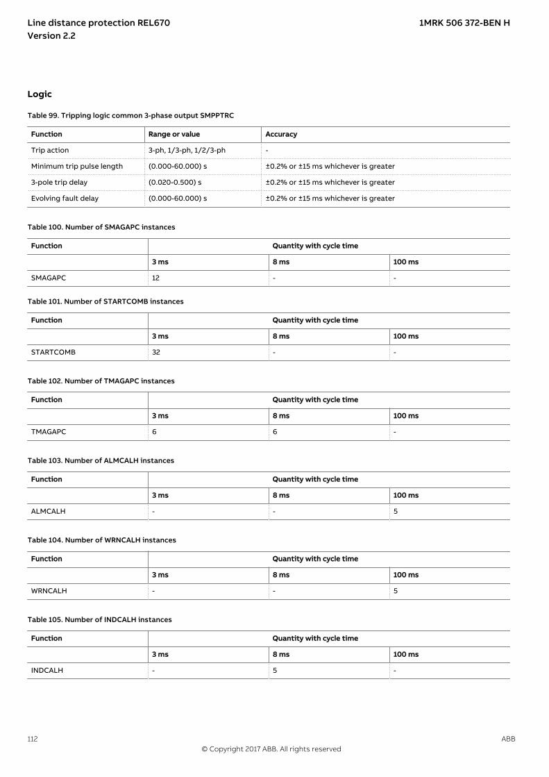
LogicM12380-1 v14
Table 99. Tripping logic common 3-phase output SMPPTRC
Function Range or value Accuracy
Trip action 3-ph, 1/3-ph, 1/2/3-ph -
Minimum trip pulse length (0.000-60.000) s ±0.2% or ±15 ms whichever is greater
3-pole trip delay (0.020-0.500) s ±0.2% or ±15 ms whichever is greater
Evolving fault delay (0.000-60.000) s ±0.2% or ±15 ms whichever is greater
GUID-1E1A829D-1F26-433A-8813-1F5A6F225418 v1
Table 100. Number of SMAGAPC instances
Function Quantity with cycle time
3 ms 8 ms 100 ms
SMAGAPC 12 - -
Table 101. Number of STARTCOMB instances
Function Quantity with cycle time
3 ms 8 ms 100 ms
STARTCOMB 32 - -
GUID-3AB1EE95-51BF-4CC4-99BD-F4ECDAACB75A v3
Table 102. Number of TMAGAPC instances
Function Quantity with cycle time
3 ms 8 ms 100 ms
TMAGAPC 6 6 -
GUID-A05AF26F-DC98-4E62-B96B-E75D19F20767 v2
Table 103. Number of ALMCALH instances
Function Quantity with cycle time
3 ms 8 ms 100 ms
ALMCALH - - 5
GUID-70B7357D-F467-4CF5-9F73-641A82D334F5 v2
Table 104. Number of WRNCALH instances
Function Quantity with cycle time
3 ms 8 ms 100 ms
WRNCALH - - 5
GUID-EAA43288-01A5-49CF-BF5B-9ABF6DC27D85 v2
Table 105. Number of INDCALH instances
Function Quantity with cycle time
3 ms 8 ms 100 ms
INDCALH - 5 -
Line distance protection REL670 1MRK 506 372-BEN HVersion 2.2
112 ABB© Copyright 2017 ABB. All rights reserved

GUID-D1179280-1D99-4A66-91AC-B7343DBA9F23 v3
Table 106. Number of AND instances
Logic block Quantity with cycle time
3 ms 8 ms 100 ms
AND 60 60 160
GUID-45DF373F-DC39-4E1B-B45B-6B454E8E0E50 v3
Table 107. Number of GATE instances
Logic block Quantity with cycle time
3 ms 8 ms 100 ms
GATE 10 10 20
GUID-0EC4192A-EF03-47C0-AEC1-09B68B411A98 v3
Table 108. Number of INV instances
Logic block Quantity with cycle time
3 ms 8 ms 100 ms
INV 90 90 240
GUID-B2E6F510-8766-4381-9618-CE02ED71FFB6 v2
Table 109. Number of LLD instances
Logic block Quantity with cycle time
3 ms 8 ms 100 ms
LLD 10 10 20
GUID-35A795D7-A6BD-4669-A023-43C497DBFB01 v4
Table 110. Number of OR instances
Logic block Quantity with cycle time
3 ms 8 ms 100 ms
OR 78 60 160
GUID-E05E5FB1-23E7-4816-84F2-1FBFFDFF2B43 v2
Table 111. Number of PULSETIMER instances
Logic block Quantity with cycle time Range or Value Accuracy
3 ms 8 ms 100 ms
PULSETIMER 10 10 20 (0.000–90000.000) s ±0.5% ±10 ms
GUID-BE6FD540-E96E-4F15-B2A2-12FFAE6C51DB v2
Table 112. Number of RSMEMORY instances
Logic block Quantity with cycle time
3 ms 8 ms 100 ms
RSMEMORY 10 10 20
GUID-7A0F4327-CA83-4FB0-AB28-7C5F17AE6354 v2
Table 113. Number of SRMEMORY instances
Logic block Quantity with cycle time
3 ms 8 ms 100 ms
SRMEMORY 10 10 20
Line distance protection REL670 1MRK 506 372-BEN HVersion 2.2
ABB 113© Copyright 2017 ABB. All rights reserved

GUID-C6C98FE0-F559-45EE-B853-464516775417 v3
Table 114. Number of TIMERSET instances
Logic block Quantity with cycle time Range or Value Accuracy
3 ms 8 ms 100 ms
TIMERSET 15 15 30 (0.000–90000.000) s ±0.5% ±10 ms
GUID-0B07F78C-10BD-4070-AFF0-6EE36454AA03 v2
Table 115. Number of XOR instances
Logic block Quantity with cycle time
3 ms 8 ms 100 ms
XOR 10 10 20
GUID-23D4121A-4C9A-4072-BBE3-6DB076EDAB79 v1
Table 116. Number of ANDQT instances
Logic block Quantity with cycle time
3 ms 8 ms 100 ms
ANDQT - 20 100
GUID-27DF23C0-A0B2-4BB0-80B5-FC7B7F7FE448 v1
Table 117. Number of INDCOMBSPQT instances
Logic block Quantity with cycle time
3 ms 8 ms 100 ms
INDCOMBSPQT - 10 10
GUID-C1E61AE5-22CF-4198-97CF-8C8043EE96D2 v1
Table 118. Number of INDEXTSPQT instances
Logic block Quantity with cycle time
3 ms 8 ms 100 ms
INDEXTSPQT - 10 10
GUID-77FEBE9B-0882-4E85-8B1A-7671807BFC02 v2
Table 119. Number of INVALIDQT instances
Logic block Quantity with cycle time
3 ms 8 ms 100 ms
INVALIDQT 10 6 6
GUID-F25B94C6-9CC9-48A0-A7A3-47627D2B56E2 v1
Table 120. Number of INVERTERQT instances
Logic block Quantity with cycle time
3 ms 8 ms 100 ms
INVERTERQT - 20 100
GUID-88B27B3C-26D2-47AF-9878-CC19018171B1 v1
Table 121. Number of ORQT instances
Logic block Quantity with cycle time
3 ms 8 ms 100 ms
ORQT - 20 100
Line distance protection REL670 1MRK 506 372-BEN HVersion 2.2
114 ABB© Copyright 2017 ABB. All rights reserved

GUID-61263951-53A8-4113-82B5-3DB3BF0D9449 v1
Table 122. Number of PULSETIMERQT instances
Logic block Quantity with cycle time Range or Value Accuracy
3 ms 8 ms 100 ms
PULSETIMERQT - 10 30 (0.000–90000.000) s ±0.5% ±10 ms
GUID-94C803B4-6C5A-4072-AB5C-20DDE98C9A70 v1
Table 123. Number of RSMEMORYQT instances
Logic block Quantity with cycle time
3 ms 8 ms 100 ms
RSMEMORYQT - 10 30
GUID-341562FB-6149-495B-8A63-200DF16A5590 v1
Table 124. Number of SRMEMORYQT instances
Logic block Quantity with cycle time
3 ms 8 ms 100 ms
SRMEMORYQT - 10 30
GUID-B6231B97-05ED-40E8-B735-1E1A50FDB85F v1
Table 125. Number of TIMERSETQT instances
Logic block Quantity with cycle time Range or Value Accuracy
3 ms 8 ms 100 ms
TIMERSETQT - 10 30 (0.000–90000.000) s ±0.5% ±10 ms
GUID-1C381E02-6B9E-44DC-828F-8B3EA7EDAA54 v1
Table 126. Number of XORQT instances
Logic block Quantity with cycle time
3 ms 8 ms 100 ms
XORQT - 10 30
Line distance protection REL670 1MRK 506 372-BEN HVersion 2.2
ABB 115© Copyright 2017 ABB. All rights reserved

GUID-19810098-1820-4765-8F0B-7D585FFC0C78 v8
Table 127. Number of instances in the extension logic package
Logic block Quantity with cycle time
3 ms 8 ms 100 ms
SLGAPC 10 10 54
VSGAPC 10 10 100
AND 80 40 100
OR 80 40 100
PULSETIMER 20 20 49
GATE — — 49
TIMERSET 34 30 49
XOR 10 10 69
LLD — — 49
SRMEMORY 10 10 110
INV 80 40 100
RSMEMORY 10 10 20
GUID-65A2876A-F779-41C4-ACD7-7662D1E7F1F2 v3
Table 128. Number of B16I instances
Function Quantity with cycle time
3 ms 8 ms 100 ms
B16I 6 4 8
GUID-3820F464-D296-4CAD-8491-F3F997359D79 v2
Table 129. Number of BTIGAPC instances
Function Quantity with cycle time
3 ms 8 ms 100 ms
BTIGAPC 4 4 8
GUID-B45901F4-B163-4696-8220-7F8CAC84D793 v2
Table 130. Number of IB16 instances
Function Quantity with cycle time
3 ms 8 ms 100 ms
IB16 6 4 8
GUID-A339BBA3-8FD0-429D-BB49-809EAC4D53B0 v2
Table 131. Number of ITBGAPC instances
Function Quantity with cycle time
3 ms 8 ms 100 ms
ITBGAPC 4 4 8
Line distance protection REL670 1MRK 506 372-BEN HVersion 2.2
116 ABB© Copyright 2017 ABB. All rights reserved

GUID-B258726E-1129-47C9-94F9-BE634A2085FA v4
Table 132. Elapsed time integrator with limit transgression and overflow supervision TEIGAPC
Function Cycle time (ms) Range or value Accuracy
Elapsed time integration 3 0 ~ 999999.9 s ±0.2% or ±20 ms whichever isgreater
8 0 ~ 999999.9 s ±0.2% or ±100 ms whichever isgreater
100 0 ~ 999999.9 s ±0.2% or ±250 ms whichever isgreater
Table 133. Number of TEIGAPC instances
Function Quantity with cycle time
3 ms 8 ms 100 ms
TEIGAPC 4 4 4
GUID-CEA332FF-838D-42B7-AEFC-C1E87809825E v3
Table 134. Number of INTCOMP instances
Function Quantity with cycle time
3 ms 8 ms 100 ms
INTCOMP 10 10 10
GUID-3FDD7677-1D86-42AD-A545-B66081C49B47 v4
Table 135. Number of REALCOMP instances
Function Quantity with cycle time
3 ms 8 ms 100 ms
REALCOMP 10 10 10
Line distance protection REL670 1MRK 506 372-BEN HVersion 2.2
ABB 117© Copyright 2017 ABB. All rights reserved

MonitoringM12386-1 v16
Table 136. Power system measurement CVMMXN
Function Range or value Accuracy
Frequency (0.95-1.05) x fr ±2.0 mHz
Voltage (10 to 300) V ±0.3% of U at U≤ 50 V±0.2% of U at U> 50 V
Current (0.1-4.0) x Ir ±0.8% of I at 0.1 x Ir< I < 0.2 x Ir± 0.5% of I at 0.2 x Ir< I < 0.5 x Ir±0.2% of I at 0.5 x Ir< I < 4.0 x Ir
Active power, P (10 to 300) V(0.1-4.0) x Ir
±0.5% of Sr at S ≤0.5 x Sr
±0.5% of S at S > 0.5 x Sr
(100 to 220) V(0.5-2.0) x Ircos φ> 0.7
±0.2% of P
Reactive power, Q (10 to 300) V(0.1-4.0) x Ir
±0.5% of Sr at S ≤0.5 x Sr
±0.5% of S at S > 0.5 x Sr
(100 to 220) V(0.5-2.0) x Ircos φ< 0.7
±0.2% of Q
Apparent power, S (10 to 300) V(0.1-4.0) x Ir
±0.5% of Sr at S ≤0.5 x Sr
±0.5% of S at S >0.5 x Sr
(100 to 220) V(0.5-2.0) x Ir
±0.2% of S
Power factor, cos (φ) (10 to 300) V(0.1-4.0) x Ir
<0.02
(100 to 220) V(0.5-2.0) x Ir
<0.01
GUID-5E04B3F9-E1B7-4974-9C0B-DE9CD4A2408F v6
Table 137. Current measurement CMMXU
Function Range or value Accuracy
Current at symmetrical load (0.1-4.0) × Ir ±0.3% of Ir at I ≤ 0.5 × Ir±0.3% of I at I > 0.5 × Ir
Phase angle at symmetricalload
(0.1-4.0) × Ir ±1.0 degrees at 0.1 × Ir < I ≤ 0.5 × Ir±0.5 degrees at 0.5 × Ir < I ≤ 4.0 × Ir
GUID-374C2AF0-D647-4159-8D3A-71190FE3CFE0 v5
Table 138. Voltage measurement phase-phase VMMXU
Function Range or value Accuracy
Voltage (10 to 300) V ±0.5% of U at U ≤ 50 V±0.2% of U at U > 50 V
Phase angle (10 to 300) V ±0.5 degrees at U ≤ 50 V±0.2 degrees at U > 50 V
Line distance protection REL670 1MRK 506 372-BEN HVersion 2.2
118 ABB© Copyright 2017 ABB. All rights reserved

GUID-ED634B6D-9918-464F-B6A4-51B78129B819 v6
Table 139. Voltage measurement phase-earth VNMMXU
Function Range or value Accuracy
Voltage (5 to 175) V ±0.5% of U at U ≤ 50 V±0.2% of U at U > 50 V
Phase angle (5 to 175) V ±0.5 degrees at U ≤ 50 V±0.2 degrees at U > 50 V
GUID-9B8A7FA5-9C98-4CBD-A162-7112869CF030 v5
Table 140. Current sequence measurement CMSQI
Function Range or value Accuracy
Current positive sequence, I1Three phase settings
(0.1–4.0) × Ir ±0.3% of Ir at I ≤ 0.5 × Ir±0.3% of I at I > 0.5 × Ir
Current zero sequence, 3I0Three phase settings
(0.1–1.0) × Ir ±0.3% of Ir at I ≤ 0.5 × Ir±0.3% of I at I > 0.5 × Ir
Current negative sequence, I2Three phase settings
(0.1–1.0) × Ir ±0.3% of Ir at I ≤ 0.5 × Ir±0.3% of I at I > 0.5 × Ir
Phase angle (0.1–4.0) × Ir ±1.0 degrees at 0.1 × Ir < I ≤ 0.5 × Ir±0.5 degrees at 0.5 × Ir < I ≤ 4.0 × Ir
GUID-47094054-A828-459B-BE6A-D7FA1B317DA7 v6
Table 141. Voltage sequence measurement VMSQI
Function Range or value Accuracy
Voltage positive sequence, U1 (10 to 300) V ±0.5% of U at U ≤ 50 V±0.2% of U at U > 50 V
Voltage zero sequence, 3U0 (10 to 300) V ±0.5% of U at U ≤ 50 V±0.2% of U at U > 50 V
Voltage negative sequence, U2 (10 to 300) V ±0.5% of U at U ≤ 50 V±0.2% of U at U > 50 V
Phase angle (10 to 300) V ±0.5 degrees at U ≤ 50 V±0.2 degrees at U > 50 V
M16080-1 v5
Table 142. Supervision of mA input signals
Function Range or value Accuracy
mA measuring function ±5, ±10, ±20 mA0-5, 0-10, 0-20, 4-20 mA
±0.1 % of set value ±0.005 mA
Max current of transducerto input
(-20.00 to +20.00) mA
Min current of transducer toinput
(-20.00 to +20.00) mA
Alarm level for input (-20.00 to +20.00) mA
Warning level for input (-20.00 to +20.00) mA
Alarm hysteresis for input (0.0-20.0) mA
Line distance protection REL670 1MRK 506 372-BEN HVersion 2.2
ABB 119© Copyright 2017 ABB. All rights reserved

M12760-1 v11
Table 143. Disturbance report DRPRDRE
Function Range or value Accuracy
Pre-fault time (0.05–9.90) s -
Post-fault time (0.1–10.0) s -
Limit time (0.5–10.0) s -
Maximum number of recordings 100, first in - first out -
Time tagging resolution 1 ms See table 182
Maximum number of analog inputs 30 + 10 (external + internallyderived)
-
Maximum number of binary inputs 352 -
Maximum number of phasors in the Trip Value recorder per recording 30 -
Maximum number of indications in a disturbance report 352 -
Maximum number of events in the Event recording per recording 150 -
Maximum number of events in the Event list 1000, first in - first out -
Maximum total recording time (3.4 s recording time and maximum numberof channels, typical value)
340 seconds (100 recordings)at 50 Hz, 280 seconds (80recordings) at 60 Hz
-
Sampling rate 1 kHz at 50 Hz1.2 kHz at 60 Hz
-
Recording bandwidth (5-300) Hz -
GUID-F034B396-6600-49EF-B0A5-8ED96766A6A0 v8
Table 144. Insulation supervision for gas medium function SSIMG
Function Range or value Accuracy
Pressure alarm level 1.00-100.00 ±10.0% of set value
Pressure lockout level 1.00-100.00 ±10.0% of set value
Temperature alarm level -40.00-200.00 ±2.5% of set value
Temperature lockout level -40.00-200.00 ±2.5% of set value
Time delay for pressure alarm (0.000-60.000) s ±0.2% or ±250ms whichever is greater
Reset time delay for pressure alarm (0.000-60.000) s ±0.2% or ±250ms whichever is greater
Time delay for pressure lockout (0.000-60.000) s ±0.2% or ±250ms whichever is greater
Time delay for temperature alarm (0.000-60.000) s ±0.2% or ±250ms whichever is greater
Reset time delay for temperature alarm (0.000-60.000) s ±0.2% or ±250ms whichever is greater
Time delay for temperature lockout (0.000-60.000) s ±0.2% or ±250ms whichever is greater
Line distance protection REL670 1MRK 506 372-BEN HVersion 2.2
120 ABB© Copyright 2017 ABB. All rights reserved

GUID-83B0F607-D898-403A-94FD-7FE8D45C73FF v8
Table 145. Insulation supervision for liquid medium function SSIML
Function Range or value Accuracy
Oil alarm level 1.00-100.00 ±10.0% of set value
Oil lockout level 1.00-100.00 ±10.0% of set value
Temperature alarm level -40.00-200.00 ±2.5% of set value
Temperature lockout level -40.00-200.00 ±2.5% of set value
Time delay for oil alarm (0.000-60.000) s ±0.2% or ±250ms whichever is greater
Reset time delay for oil alarm (0.000-60.000) s ±0.2% or ±250ms whichever is greater
Time delay for oil lockout (0.000-60.000) s ±0.2% or ±250ms whichever is greater
Time delay for temperature alarm (0.000-60.000) s ±0.2% or ±250ms whichever is greater
Reset time delay for temperature alarm (0.000-60.000) s ±0.2% or ±250ms whichever is greater
Time delay for temperature lockout (0.000-60.000) s ±0.2% or ±250ms whichever is greater
GUID-B6799420-D726-460E-B02F-C7D4F1937432 v9
Table 146. Circuit breaker condition monitoring SSCBR
Function Range or value Accuracy
Alarm level for open and close travel time (0 – 200) ms ±3 ms
Alarm level for number of operations (0 – 9999) -
Independent time delay for spring chargingtime alarm
(0.00 – 60.00) s ±0.2% or ±30 ms whichever is greater
Independent time delay for gas pressurealarm
(0.00 – 60.00) s ±0.2% or ±30 ms whichever is greater
Independent time delay for gas pressurelockout
(0.00 – 60.00) s ±0.2% or ±30 ms whichever is greater
CB Contact Travel Time, opening andclosing
±3 ms
Remaining Life of CB ±2 operations
Accumulated Energy ±1.0% or ±0.5 whichever is greater
M14987-1 v6
Table 147. Fault locator LMBRFLO
Function Value or range Accuracy
Reactive and resistive reach (0.001-1500.000) Ω/phase ±2.0% static accuracyConditions:Voltage range: (0.1-1.1) x Ur
Current range: (0.5-30) x Ir
Phase selection According to input signals -
Maximum number of faultlocations
100 -
Line distance protection REL670 1MRK 506 372-BEN HVersion 2.2
ABB 121© Copyright 2017 ABB. All rights reserved

M12700-1 v4
Table 148. Event list
Function Value
Buffer capacity Maximum number of events in the list 1000
Resolution 1 ms
Accuracy Depending on time synchronizing
M13765-1 v5
Table 149. Indications
Function Value
Buffer capacity Maximum number of indications presented for single disturbance 352
Maximum number of recorded disturbances 100
M12702-1 v4
Table 150. Event recorder
Function Value
Buffer capacity Maximum number of events in disturbance report 150
Maximum number of disturbance reports 100
Resolution 1 ms
Accuracy Depending on timesynchronizing
M13747-1 v5
Table 151. Trip value recorder
Function Value
Buffer capacity
Maximum number of analog inputs 30
Maximum number of disturbance reports 100
M12384-1 v7
Table 152. Disturbance recorder
Function Value
Buffer capacity Maximum number of analog inputs 40
Maximum number of binary inputs 352
Maximum number of disturbance reports 100
Maximum total recording time (3.4 s recording time and maximumnumber of channels, typical value)
340 seconds (100 recordings) at 50 Hz280 seconds (80 recordings) at 60 Hz
GUID-C43B8654-60FE-4E20-8328-754C238F4AD0 v3
Table 153. Event counter with limit supervision L4UFCNT
Function Range or value Accuracy
Counter value 0-65535 -
Max. count up speed 30 pulses/s (50% duty cycle) -
Line distance protection REL670 1MRK 506 372-BEN HVersion 2.2
122 ABB© Copyright 2017 ABB. All rights reserved

GUID-F5E124E3-0B85-41AC-9830-A2362FD289F2 v1
Table 154. Running hour-meter TEILGAPC
Function Range or value Accuracy
Time limit for alarm supervision, tAlarm (0 - 99999.9) hours ±0.1% of set value
Time limit for warning supervision,tWarning
(0 - 99999.9) hours ±0.1% of set value
Time limit for overflow supervision Fixed to 99999.9 hours ±0.1%
GUID-3763D0D6-AD44-4C9B-91E4-050C0B63C7EA v1
Table 155. Through fault monitoring PTRSTHR
Function Range or value Accuracy
Operate current (50-1000)% of IBase ±1.0% of Ir at I ≤ Ir±1.0% of I at I > Ir
Reset ratio > 95% at (50-1000)% of IBase –
GUID-09EC65AC-C60B-4256-A601-FE2CC90D26EC v1
Table 156. Current harmonic monitoring CHMMHAI (50/60 Hz)
Function Range or value Accuracy
Fundamental Harmonic
Frequency (0.95 - 1.05) X fr 2nd order to 5th order (0.1 - 0.5) X Ir ± 2 mHz
True RMS (0.1 to 1) X Ir None ± 0.5%
1 X Ir 2nd order to 5th order (0.1 - 0.5) X Ir ± 2%
Fundamental (0.1 to 1) X Ir None ± 0.5%
1 X Ir 2nd order to 5th order (0.1 - 0.5) X Ir ± 0.5%
Crest Factor (0.1 to 1) X Ir None ± 2%
HarmonicAmplitude
(0.1 to 1) X Ir 2nd order to 5th order (0.1 - 0.5) X Ir ± 5%
Total DemandDistortion (TDD)
(0.1 to 1) X Ir 2nd order to 5th order (0.1 - 0.5) X Ir ± 6%
Total HarmonicDistortion (ITHD)
(0.1 to 1) X Ir 2nd order to 5th order (0.1 - 0.5) X Ir ± 6%
Line distance protection REL670 1MRK 506 372-BEN HVersion 2.2
ABB 123© Copyright 2017 ABB. All rights reserved
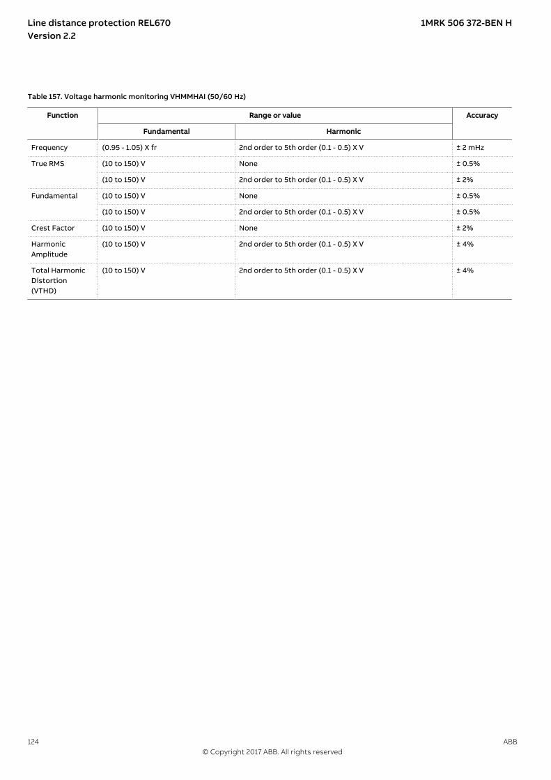
GUID-2068BBA0-9026-48D0-9DEB-301BCB3C600C v1
Table 157. Voltage harmonic monitoring VHMMHAI (50/60 Hz)
Function Range or value Accuracy
Fundamental Harmonic
Frequency (0.95 - 1.05) X fr 2nd order to 5th order (0.1 - 0.5) X V ± 2 mHz
True RMS (10 to 150) V None ± 0.5%
(10 to 150) V 2nd order to 5th order (0.1 - 0.5) X V ± 2%
Fundamental (10 to 150) V None ± 0.5%
(10 to 150) V 2nd order to 5th order (0.1 - 0.5) X V ± 0.5%
Crest Factor (10 to 150) V None ± 2%
HarmonicAmplitude
(10 to 150) V 2nd order to 5th order (0.1 - 0.5) X V ± 4%
Total HarmonicDistortion(VTHD)
(10 to 150) V 2nd order to 5th order (0.1 - 0.5) X V ± 4%
Line distance protection REL670 1MRK 506 372-BEN HVersion 2.2
124 ABB© Copyright 2017 ABB. All rights reserved
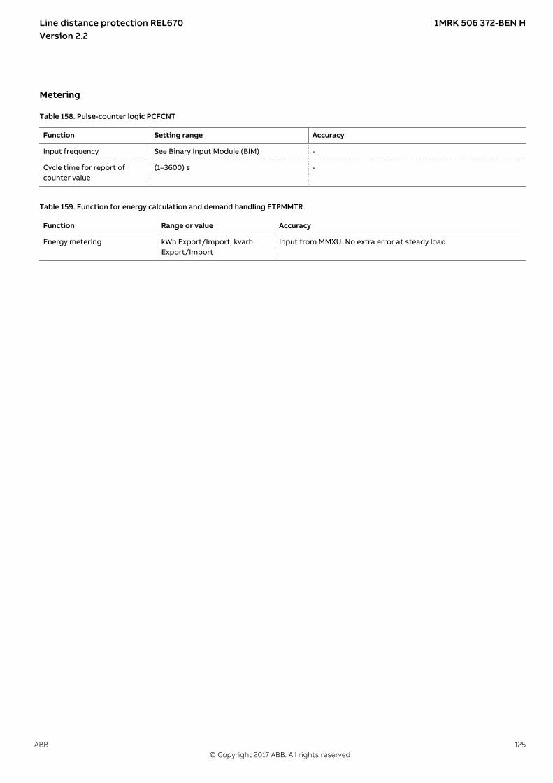
MeteringM13404-2 v5
Table 158. Pulse-counter logic PCFCNT
Function Setting range Accuracy
Input frequency See Binary Input Module (BIM) -
Cycle time for report ofcounter value
(1–3600) s -
SEMOD153707-2 v5
Table 159. Function for energy calculation and demand handling ETPMMTR
Function Range or value Accuracy
Energy metering kWh Export/Import, kvarhExport/Import
Input from MMXU. No extra error at steady load
Line distance protection REL670 1MRK 506 372-BEN HVersion 2.2
ABB 125© Copyright 2017 ABB. All rights reserved
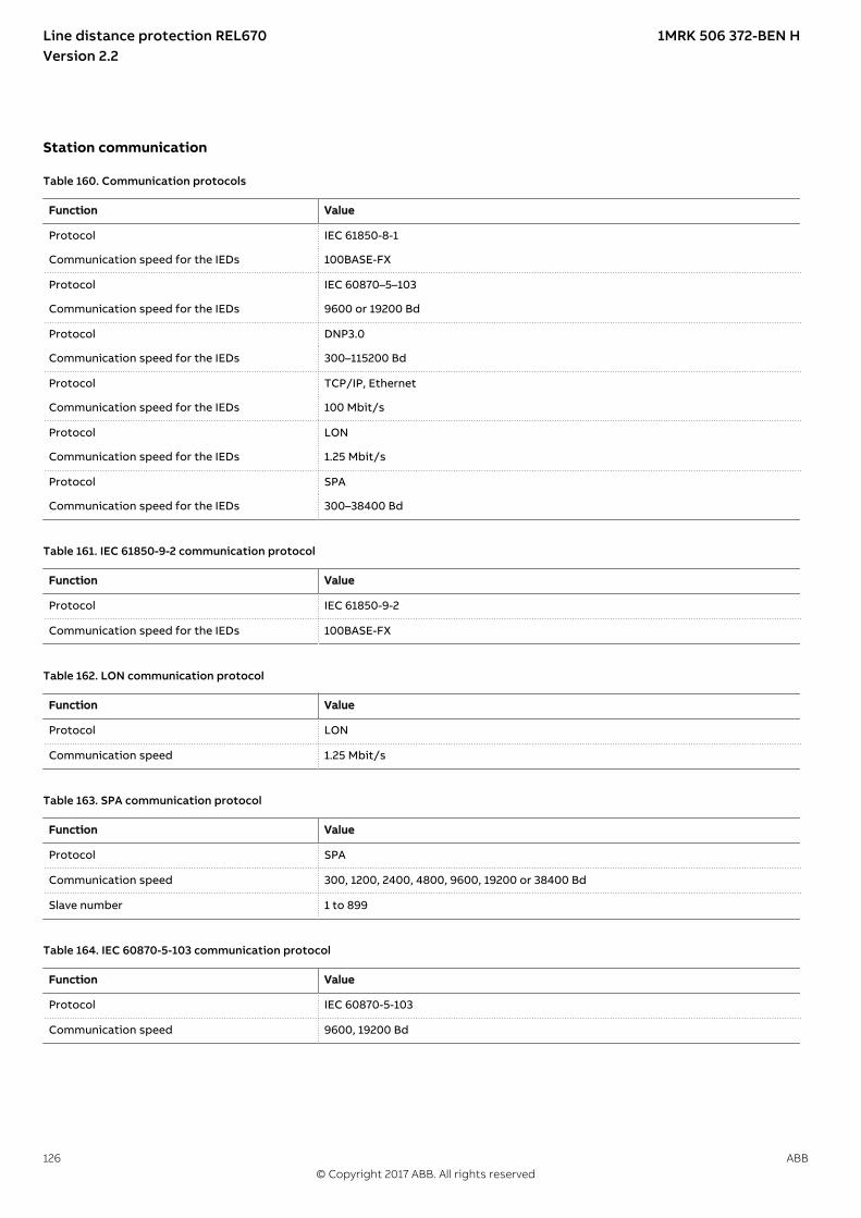
Station communicationM15031-1 v9
Table 160. Communication protocols
Function Value
Protocol IEC 61850-8-1
Communication speed for the IEDs 100BASE-FX
Protocol IEC 60870–5–103
Communication speed for the IEDs 9600 or 19200 Bd
Protocol DNP3.0
Communication speed for the IEDs 300–115200 Bd
Protocol TCP/IP, Ethernet
Communication speed for the IEDs 100 Mbit/s
Protocol LON
Communication speed for the IEDs 1.25 Mbit/s
Protocol SPA
Communication speed for the IEDs 300–38400 Bd
GUID-E8B5405C-241C-4DC2-8AB1-3FA77343A4DE v2
Table 161. IEC 61850-9-2 communication protocol
Function Value
Protocol IEC 61850-9-2
Communication speed for the IEDs 100BASE-FX
M11927-1 v2
Table 162. LON communication protocol
Function Value
Protocol LON
Communication speed 1.25 Mbit/s
M11901-1 v2
Table 163. SPA communication protocol
Function Value
Protocol SPA
Communication speed 300, 1200, 2400, 4800, 9600, 19200 or 38400 Bd
Slave number 1 to 899
M11921-1 v4
Table 164. IEC 60870-5-103 communication protocol
Function Value
Protocol IEC 60870-5-103
Communication speed 9600, 19200 Bd
Line distance protection REL670 1MRK 506 372-BEN HVersion 2.2
126 ABB© Copyright 2017 ABB. All rights reserved

M12589-1 v4
Table 165. SLM – LON port
Quantity Range or value
Optical connector Glass fiber: type STPlastic fiber: type HFBR snap-in
Fiber, optical budget Glass fiber: 11 dB (1000m/3000 ft typically *)Plastic fiber: 7 dB (10m/35ft typically *)
Fiber diameter Glass fiber: 62.5/125 mmPlastic fiber: 1 mm
*) depending on optical budget calculation
SEMOD117441-2 v5
Table 166. SLM – SPA/IEC 60870-5-103/DNP3 port
Quantity Range or value
Optical connector Glass fiber: type STPlastic fiber: type HFBR snap-in
Fiber, optical budget Glass fiber: 11 dB (1000m/3000ft m typically *)Plastic fiber: 7 dB (25m/80ft m typically *)
Fiber diameter Glass fiber: 62.5/125 mmPlastic fiber: 1 mm
*) depending on optical budget calculation
SEMOD158710-2 v2
Table 167. Galvanic RS485 communication module
Quantity Range or value
Communication speed 2400–19200 bauds
External connectors RS-485 6-pole connectorSoft ground 2-pole connector
SEMOD55310-2 v13
Table 168. SFP - Optical ethernet port
Quantity Rated value
Number of channels Up to 6 single or 3 redundant or a combination of single and redundant links forcommunication using any protocol
Standard IEEE 802.3u 100BASE-FX
Type of fiber 62.5/125 mm multimode fiber
Wave length 1310 nm, Class 1 laser safety
Optical connector Type LC
Communication speed Fast Ethernet 100 Mbit/s
Line distance protection REL670 1MRK 506 372-BEN HVersion 2.2
ABB 127© Copyright 2017 ABB. All rights reserved

Table 169. SFP - Galvanic RJ45
Quantity Rated value
Number of channels Up to 6 single or 3 redundant or a combination of single and redundant links forcommunication using any protocol
Standard IEEE 802.3u 100BASE-TX
Type of cable Cat5e FTP
Connector Type RJ45
Communication Speed Fast Ethernet 100 Mbit/s
GUID-8651FF22-C007-4D53-B7E3-686A30F37CB6 v6
Table 170. Ethernet redundancy protocols, IEC 62439-3
Function Value
Protocol IEC 62439-3 Ed.1 Parallel Redundancy Protocol (PRP-0)
Communication speed 100Base-FX
Protocol IEC 62439-3 Ed.2 Parallel Redundancy Protocol (PRP-1)
Communication speed 100Base-FX
Protocol IEC 62439-3 Ed.2 High-availability Seamless Redundancy (HSR)
Communication speed 100Base-FX
Connectors Optical, type LC
Line distance protection REL670 1MRK 506 372-BEN HVersion 2.2
128 ABB© Copyright 2017 ABB. All rights reserved

Remote communication
M12756-1 v12
Table 171. Line data communication module
Characteristic Range or value
Type of LDCM Short range (SR) Medium range (MR) Long range (LR)
Type of fiber Multi-mode fiberglass 62.5/125 µm Multi-mode fiberglass 50/125 µm
Single-mode fiberglass 9/125 µm
Single-mode fiberglass 9/125 µm
Peak Emission Wave lengthNominalMaximumMinimum
820 nm865 nm792 nm
1310 nm1330 nm1290 nm
1550 nm1580 nm1520 nm
Optical budgetMulti-mode fiber glass 62.5/125 mm
18.8 dB (typicaldistance about 3km/2 mile *)
26.8 dB (typicaldistance 80 km/50mile *)
28.7 dB (typicaldistance 120 km/68mile *)
Multi-mode fiber glass 50/125 mm 11.5 dB (typicaldistance about 2km/1 mile *)
Optical connector Type ST Type FC/PC Type FC/PC
Protocol C37.94 C37.94implementation **)
C37.94implementation **)
Data transmission Synchronous Synchronous Synchronous
Transmission rate / Data rate 2 Mbit/s / 64 kbit/s 2 Mbit/s / 64 kbit/s 2 Mbit/s / 64 kbit/s
Clock source Internal or derivedfrom receivedsignal
Internal or derivedfrom receivedsignal
Internal or derivedfrom received signal
*) depending on optical budget calculation**) C37.94 originally defined just for multi-mode; using same header, configuration and data format as C37.94
GUID-83EC40D0-ABCF-4292-B3DF-155C3A556B76 v4
Table 172. Galvanic X.21 line data communication module (X.21-LDCM)
Quantity Range or value
Connector, X.21 Micro D-sub, 15-pole male, 1.27 mm (0.050") pitch
Connector, ground selection 2 pole screw terminal
Standard CCITT X21
Communication speed 64 kbit/s
Insulation 1 kV
Maximum cable length 10 m
Line distance protection REL670 1MRK 506 372-BEN HVersion 2.2
ABB 129© Copyright 2017 ABB. All rights reserved

HardwareIED
SEMOD53385-1 v1M11778-1 v7
Table 173. Case
Material Steel sheet
Front plate Stainless steel with cut-out for HMI
Surface treatment Aluzink preplated steel
Finish Light grey (RAL 7035)
M12327-1 v5
Table 174. Water and dust protection level according to IEC 60529
Front IP40 (IP54 with sealing strip)
Sides, top and bottom IP40
Rear side IP20 with screw compression typeIP10 with ring lug terminals
M11777-1 v7
Table 175. Weight
Case size Weight
6U, 1/2 x 19” £ 7.5 kg/16 lb
6U, 3/4 x 19” £ 15 kg/33 lb
6U, 1/1 x 19” £ 15 kg/33 lb
Electrical safetyGUID-2825B541-DD31-4DAF-B5B3-97555F81A1C2 v1GUID-1CF5B10A-CF8B-407D-8D87-F4B48B43C2B2 v2
Table 176. Electrical safety according to IEC 60255-27
Equipment class I (protective earthed)
Overvoltage category III
Pollution degree 2 (normally only non-conductive pollution occurs except that occasionally a temporary conductivity caused bycondensation is to be expected)
Connection systemSEMOD53371-1 v1SEMOD53376-2 v6
Table 177. CT and VT circuit connectors
Connector type Rated voltage and current Maximum conductor area
Screw compression type 250 V AC, 20 A 4 mm2 (AWG12)2 x 2.5 mm2 (2 x AWG14)
Terminal blocks suitable for ring lug terminals 250 V AC, 20 A 4 mm2 (AWG12)
M12583-1 v8
Table 178. Auxiliary power supply and binary I/O connectors
Connector type Rated voltage Maximum conductor area
Screw compression type 250 V AC 2.5 mm2 (AWG14)2 × 1 mm2 (2 x AWG18)
Terminal blocks suitable for ring lug terminals 300 V AC 3 mm2 (AWG14)
Line distance protection REL670 1MRK 506 372-BEN HVersion 2.2
130 ABB© Copyright 2017 ABB. All rights reserved

Because of limitations of space, whenring lug terminal is ordered for BinaryI/O connections, one blank slot isnecessary between two adjacent I/Omodules. Please refer to the orderingparticulars for details.
GUID-96676D5D-0835-44DA-BC22-058FD18BDF34 v3
Table 179. NUM: Communication ports
NUM 4 Ethernet ports1 Basic, 3 Optional
Ethernet connection type SFP Optical LC or Galvanic RJ45
Carrier modules supported OEM, LDCM
GUID-4876834C-CABB-400B-B84B-215F65D8AF92 v3
Table 180. OEM: Number of Ethernet ports
OEM 2 Ethernet Ports
Ethernet connection type SFP Optical LC or Galvanic RJ45
Line distance protection REL670 1MRK 506 372-BEN HVersion 2.2
ABB 131© Copyright 2017 ABB. All rights reserved

Basic IED functionsM11963-1 v5
Table 181. Self supervision with internal event list
Data Value
Recording manner Continuous, event controlled
List size 40 events, first in-first out
M12331-1 v9
Table 182. Time synchronization, time tagging
Function Value
Time tagging accuracy of the synchrophasor data ± 1 µs
Time tagging resolution, events and sampled measurement values 1 ms
Time tagging error with synchronization once/min (minute pulse synchronization), events and sampledmeasurement values
± 1.0 ms typically
Time tagging error with SNTP synchronization, sampled measurement values ± 1.0 ms typically
GUID-8AEB81D0-1731-46DF-A206-D2E758823575 v2
Table 183. Time synchronization PTP: IEC/IEEE 61850-9-3
Supported types of clock Boundary Clock (BC), Ordinary Clock (OC), Transparent Clock (TC)
Accuracy According to standard IEC/IEEE 61850-9-3
Number of nodes According to standard IEC/IEEE 61850-9-3
Ports supported All rear Ethernet ports
SEMOD55660-2 v3
Table 184. GPS time synchronization module (GTM)
Function Range or value Accuracy
Receiver – ±1µs relative UTC
Time to reliable time reference with antenna in newposition or after power loss longer than 1 month
<30 minutes –
Time to reliable time reference after a power losslonger than 48 hours
<15 minutes –
Time to reliable time reference after a power lossshorter than 48 hours
<5 minutes –
SEMOD55693-2 v5
Table 185. GPS – Antenna and cable
Function Value
Max antenna cable attenuation 26 db @ 1.6 GHz
Antenna cable impedance 50 ohm
Lightning protection Must be provided externally
Antenna cable connector SMA in receiver endTNC in antenna end
Accuracy +/-1μs
Line distance protection REL670 1MRK 506 372-BEN HVersion 2.2
132 ABB© Copyright 2017 ABB. All rights reserved

SEMOD141136-2 v10
Table 186. IRIG-B
Quantity Rated value
Number of channels IRIG-B 1
Number of optical channels 1
Electrical connector:
Electrical connector IRIG-B BNC
Pulse-width modulated 5 Vpp
Amplitude modulated– low level– high level
1-3 Vpp3 x low level, max 9 Vpp
Supported formats IRIG-B 00x, IRIG-B 12x
Accuracy +/-10μs for IRIG-B 00x and +/-100μs for IRIG-B 12x
Input impedance 100 k ohm
Optical connector:
Optical connector IRIG-B Type ST
Type of fiber 62.5/125 μm multimode fiber
Supported formats IRIG-B 00x
Accuracy +/- 1μs
Line distance protection REL670 1MRK 506 372-BEN HVersion 2.2
ABB 133© Copyright 2017 ABB. All rights reserved

Inverse characteristicM12388-1 v23
Table 187. ANSI Inverse time characteristics
Function Range or value Accuracy
Operating characteristic:
( )1P
At B kI
æ öç ÷= + ×ç ÷-è ø
EQUATION1249-SMALL V3 EN-US
Reset characteristic:
( )2 1= ×
-
trt kI
EQUATION1250-SMALL V1 EN-US
I = Imeasured/Iset
0.05 ≤ k ≤ 999.001.5 x Iset ≤ I ≤ 20 x Iset
ANSI/IEEE C37.112 ,±2.0% or ±40 mswhichever is greater
ANSI Extremely Inverse A=28.2, B=0.1217, P=2.0 , tr=29.1
ANSI Very inverse A=19.61, B=0.491, P=2.0 , tr=21.6
ANSI Normal Inverse A=0.0086, B=0.0185, P=0.02, tr=0.46
ANSI Moderately Inverse A=0.0515, B=0.1140, P=0.02, tr=4.85
ANSI Long Time Extremely Inverse A=64.07, B=0.250, P=2.0, tr=30
ANSI Long Time Very Inverse A=28.55, B=0.712, P=2.0, tr=13.46
ANSI Long Time Inverse A=0.086, B=0.185, P=0.02, tr=4.6
Line distance protection REL670 1MRK 506 372-BEN HVersion 2.2
134 ABB© Copyright 2017 ABB. All rights reserved

Table 188. IEC Inverse time characteristics
Function Range or value Accuracy
Operating characteristic:
( )1= ×
-
æ öç ÷ç ÷è ø
P
At k
I
EQUATION1251-SMALL V1 EN-US
I = Imeasured/Iset
0.05 ≤ k ≤ 999.001.5 x Iset ≤ I ≤ 20 x Iset
IEC 60255-151, ±2.0%or ±40 ms whichever isgreater
IEC Normal Inverse A=0.14, P=0.02
IEC Very inverse A=13.5, P=1.0
IEC Inverse A=0.14, P=0.02
IEC Extremely inverse A=80.0, P=2.0
IEC Short time inverse A=0.05, P=0.04
IEC Long time inverse A=120, P=1.0
Programmable characteristicOperate characteristic:
( )= + ×
-
æ öç ÷ç ÷è ø
P
At B k
I C
EQUATION1370-SMALL V1 EN-US
Reset characteristic:
( )= ×
-PR
TRt k
I CR
EQUATION1253-SMALL V1 EN-US
I = Imeasured/Iset
k = (0.05-999) in steps of 0.01A=(0.005-200.000) in steps of 0.001B=(0.00-20.00) in steps of 0.01C=(0.1-10.0) in steps of 0.1P=(0.005-3.000) in steps of 0.001TR=(0.005-100.000) in steps of 0.001CR=(0.1-10.0) in steps of 0.1PR=(0.005-3.000) in steps of 0.001
The parameter setting Characteristn =Reserved (where, n = 1 - 4) shall not beused, since this parameter setting isfor future use and not implementedyet.
Line distance protection REL670 1MRK 506 372-BEN HVersion 2.2
ABB 135© Copyright 2017 ABB. All rights reserved

Table 189. RI and RD type inverse time characteristics
Function Range or value Accuracy
RI type inverse characteristic
1
0.2360.339
= ×
-
t k
IEQUATION1137-SMALL V1 EN-US
I = Imeasured/Iset
0.05 ≤ k ≤ 999.001.5 x Iset ≤ I ≤ 20 x Iset
IEC 60255-151, ±2.0%or ±40 ms whichever isgreater
RD type logarithmic inversecharacteristic
5.8 1.35= - ×æ öç ÷è ø
tI
Ink
EQUATION1138-SMALL V1 EN-US
I = Imeasured/Iset
GUID-19F8E187-4ED0-48C3-92F6-0D9EAA2B39BB v4
Table 190. ANSI Inverse time characteristics for Sensitive directional residual overcurrent and power protection
Function Range or value Accuracy
Operating characteristic:
( )1P
At B kI
æ öç ÷= + ×ç ÷-è ø
EQUATION1249-SMALL V3 EN-US
Reset characteristic:
( )2 1= ×
-
trt kI
EQUATION1250-SMALL V1 EN-US
I = Imeasured/Iset
0.05 ≤ k ≤ 2.001.5 x Iset ≤ I ≤ 20 x Iset
ANSI/IEEE C37.112 ,±5.0% or ±160 mswhichever is greater
ANSI Extremely Inverse A=28.2, B=0.1217, P=2.0 , tr=29.1
ANSI Very inverse A=19.61, B=0.491, P=2.0 , tr=21.6
ANSI Normal Inverse A=0.0086, B=0.0185, P=0.02, tr=0.46
ANSI Moderately Inverse A=0.0515, B=0.1140, P=0.02, tr=4.85
ANSI Long Time Extremely Inverse A=64.07, B=0.250, P=2.0, tr=30
ANSI Long Time Very Inverse A=28.55, B=0.712, P=2.0, tr=13.46
ANSI Long Time Inverse A=0.086, B=0.185, P=0.02, tr=4.6
Line distance protection REL670 1MRK 506 372-BEN HVersion 2.2
136 ABB© Copyright 2017 ABB. All rights reserved

Table 191. IEC Inverse time characteristics for Sensitive directional residual overcurrent and power protection
Function Range or value Accuracy
Operating characteristic:
( )1= ×
-
æ öç ÷ç ÷è ø
P
At k
I
EQUATION1251-SMALL V1 EN-US
I = Imeasured/Iset
0.05 ≤ k ≤ 2.001.5 x Iset ≤ I ≤ 20 x Iset
IEC 60255-151, ±5.0%or ±160 ms whicheveris greater
IEC Normal Inverse A=0.14, P=0.02
IEC Very inverse A=13.5, P=1.0
IEC Inverse A=0.14, P=0.02
IEC Extremely inverse A=80.0, P=2.0
IEC Short time inverse A=0.05, P=0.04
IEC Long time inverse A=120, P=1.0
Programmable characteristicOperate characteristic:
( )= + ×
-
æ öç ÷ç ÷è ø
P
At B k
I C
EQUATION1370-SMALL V1 EN-US
Reset characteristic:
( )= ×
-PR
TRt k
I CR
EQUATION1253-SMALL V1 EN-US
I = Imeasured/Iset
k = (0.05-2.00) in steps of 0.01A=(0.005-200.000) in steps of 0.001B=(0.00-20.00) in steps of 0.01C=(0.1-10.0) in steps of 0.1P=(0.005-3.000) in steps of 0.001TR=(0.005-100.000) in steps of 0.001CR=(0.1-10.0) in steps of 0.1PR=(0.005-3.000) in steps of 0.001
Table 192. RI and RD type inverse time characteristics for Sensitive directional residual overcurrent and power protection
Function Range or value Accuracy
RI type inverse characteristic
1
0.2360.339
= ×
-
t k
IEQUATION1137-SMALL V1 EN-US
I = Imeasured/Iset
0.05 ≤ k ≤ 2.001.5 x Iset ≤ I ≤ 20 x Iset
IEC 60255-151, ±5.0%or ±160 ms whicheveris greater
RD type logarithmic inversecharacteristic
5.8 1.35= - ×æ öç ÷è ø
tI
Ink
EQUATION1138-SMALL V1 EN-US
I = Imeasured/Iset
Line distance protection REL670 1MRK 506 372-BEN HVersion 2.2
ABB 137© Copyright 2017 ABB. All rights reserved
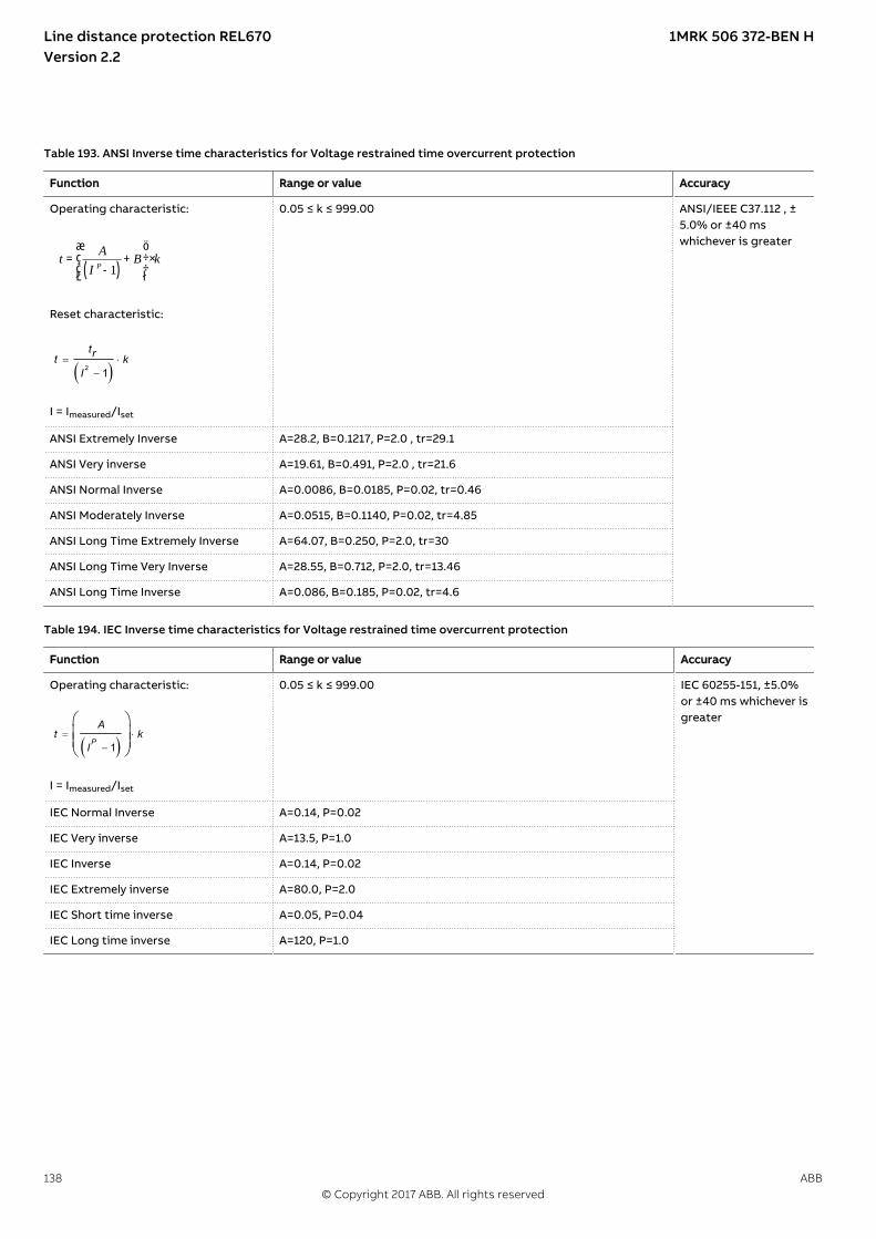
GUID-2AE8C92E-5DA8-487F-927D-8E553EE29240 v2
Table 193. ANSI Inverse time characteristics for Voltage restrained time overcurrent protection
Function Range or value Accuracy
Operating characteristic:
( )1P
At B kI
æ öç ÷= + ×ç ÷-è ø
EQUATION1249-SMALL V3 EN-US
Reset characteristic:
( )2 1= ×
-
trt kI
EQUATION1250-SMALL V1 EN-US
I = Imeasured/Iset
0.05 ≤ k ≤ 999.00 ANSI/IEEE C37.112 , ±5.0% or ±40 mswhichever is greater
ANSI Extremely Inverse A=28.2, B=0.1217, P=2.0 , tr=29.1
ANSI Very inverse A=19.61, B=0.491, P=2.0 , tr=21.6
ANSI Normal Inverse A=0.0086, B=0.0185, P=0.02, tr=0.46
ANSI Moderately Inverse A=0.0515, B=0.1140, P=0.02, tr=4.85
ANSI Long Time Extremely Inverse A=64.07, B=0.250, P=2.0, tr=30
ANSI Long Time Very Inverse A=28.55, B=0.712, P=2.0, tr=13.46
ANSI Long Time Inverse A=0.086, B=0.185, P=0.02, tr=4.6
Table 194. IEC Inverse time characteristics for Voltage restrained time overcurrent protection
Function Range or value Accuracy
Operating characteristic:
( )1= ×
-
æ öç ÷ç ÷è ø
P
At k
I
EQUATION1251-SMALL V1 EN-US
I = Imeasured/Iset
0.05 ≤ k ≤ 999.00 IEC 60255-151, ±5.0%or ±40 ms whichever isgreater
IEC Normal Inverse A=0.14, P=0.02
IEC Very inverse A=13.5, P=1.0
IEC Inverse A=0.14, P=0.02
IEC Extremely inverse A=80.0, P=2.0
IEC Short time inverse A=0.05, P=0.04
IEC Long time inverse A=120, P=1.0
Line distance protection REL670 1MRK 506 372-BEN HVersion 2.2
138 ABB© Copyright 2017 ABB. All rights reserved

SEMOD116978-2 v10
Table 195. Inverse time characteristics for overvoltage protection
Function Range or value Accuracy
Type A curve:
=- >
>
æ öç ÷è ø
tk
U U
UEQUATION1436-SMALL V1 EN-US
U> = Uset
U = Umeasured
k = (0.05-1.10) in steps of 0.01 ±5.0% or ±45 mswhichever is greater
Type B curve:
2.0
4800.035
32 0.5n
n
kt
U U
U
IECEQUATION2423 V2 EN-US
k = (0.05-1.10) in steps of 0.01
Type C curve:
3.0480 0.035
32 0.5n
ktU UU
×= +
- >æ ö× -ç ÷>è øIECEQUATION2421 V1 EN-US
k = (0.05-1.10) in steps of 0.01
Programmable curve:
×= +
- >× -
>
æ öç ÷è ø
P
k At D
U UB C
UEQUATION1439-SMALL V1 EN-US
k = (0.05-1.10) in steps of 0.01A = (0.005-200.000) in steps of 0.001B = (0.50-100.00) in steps of 0.01C = (0.0-1.0) in steps of 0.1D = (0.000-60.000) in steps of 0.001P = (0.000-3.000) in steps of 0.001
Line distance protection REL670 1MRK 506 372-BEN HVersion 2.2
ABB 139© Copyright 2017 ABB. All rights reserved

Table 196. Inverse time characteristics for undervoltage protection
Function Range or value Accuracy
Type A curve:
=< -
<
æ öç ÷è ø
kt
U U
UEQUATION1431-SMALL V1 EN-US
U< = Uset
U = Umeasured
k = (0.05-1.10) in steps of 0.01 ±5.0% or ±45 mswhichever is greater
Type B curve:
2.0
4800.055
32 0.5
×= +
< -× -
<
æ öç ÷è ø
kt
U U
UEQUATION1432-SMALL V1 EN-US
U< = Uset
U = Umeasured
k = (0.05-1.10) in steps of 0.01
Programmable curve:
×= +
< -× -
<
é ùê úê úê úæ öê úç ÷ë è ø û
P
k At D
U UB C
UEQUATION1433-SMALL V1 EN-US
U< = Uset
U = Umeasured
k = (0.05-1.10) in steps of 0.01A = (0.005-200.000) in steps of 0.001B = (0.50-100.00) in steps of 0.01C = (0.0-1.0) in steps of 0.1D = (0.000-60.000) in steps of 0.001P = (0.000-3.000) in steps of 0.001
Line distance protection REL670 1MRK 506 372-BEN HVersion 2.2
140 ABB© Copyright 2017 ABB. All rights reserved

Table 197. Inverse time characteristics for residual overvoltage protection
Function Range or value Accuracy
Type A curve:
=- >
>
æ öç ÷è ø
tk
U U
UEQUATION1436-SMALL V1 EN-US
U> = Uset
U = Umeasured
k = (0.05-1.10) in stepsof 0.01
±5.0% or ±45 ms whichever is greater
Type B curve:
2.0
480
32 0.5
=⋅
− >⋅ −
0.035+
>
tk
U U
UEQUATION1437-SMALL V2 EN-US
k = (0.05-1.10) in stepsof 0.01
Type C curve:
3.0
480
32 0.5
=⋅
⋅ −− >
0.035+
>
tk
U U
UEQUATION1438-SMALL V2 EN-US
k = (0.05-1.10) in stepsof 0.01
Programmable curve:
×= +
- >× -
>
æ öç ÷è ø
P
k At D
U UB C
UEQUATION1439-SMALL V1 EN-US
k = (0.05-1.10) in stepsof 0.01A = (0.005-200.000) insteps of 0.001B = (0.50-100.00) insteps of 0.01C = (0.0-1.0) in steps of0.1D = (0.000-60.000) insteps of 0.001P = (0.000-3.000) insteps of 0.001
Line distance protection REL670 1MRK 506 372-BEN HVersion 2.2
ABB 141© Copyright 2017 ABB. All rights reserved

26. Ordering for customized IEDGUID-1A467B6A-5034-4443-87DE-C8DD2022079C v11
Table 198. General guidelines
GuidelinesCarefully read and follow the set of rules to ensure problem-free order management.Please refer to the available functions table for included application functions.PCM600 can be used to make changes and/or additions to the delivered factory configuration of the pre-configured.
Table 199. Example ordering code
To obtain the complete ordering code, please combine code from the selection tables, as given in the example below.The selected qty of each table must be filled in, if no selection is possible the code is 0
Example of a complete code: REL670*2.2-F00X00 - A0000030000000110 - B55200002202000010110210000 - C3300332122020022241000300 - D22212011 -E22200 - F4 - S6 - G032 - H20401100000 - K20201111 - L1100 - M06102 - P11100000000000100 - B1X0 - AC - CA - B - A3X0 - CD1D1ARGN1N1XXXXXXX -KKKXXHKKLAGXSY
Product definition - Differential protection -
REL670* 2.2 - F00 X00
- A 0 0 0 0 0 0 0 0 0 0 0 0 0 -
Impedance protection -
B 1 0 0 0 0 -
Current protection -
C 00 0 00 1 0 0 0 0 0 -
Voltage protection - Frequency protection - Multipurposeprotection
- Generalcalculation
-
D 0 1 - E 00 - F - S -
Secondary system supervision - Control -
G - H 0 0 0 0 0 0 0 -
Schemecommunication
- Logic - Monitoring - Station communication -
K - L 00 - M 0 - P 0 0 0 0 0 0 0 0 0 0 0 0 0 -
Language - Casing andmounting
- Powersupply
- HMI - Analogsystem
- Binary input/output -
B1 - - - - - -
Station communication, remote end serial communication and time synchronization
K
Table 200. Product definition
REL670* 2.2 F00 X00
Table 201. Product definition ordering codes
Product REL670*
Product version 2.2
Configuration alternative
Line distance protection REL670 F00
ACT configuration
ABB Standard configuration X00
Ordering number
Line distance protection REL670 1MRK002812-AG
Line distance protection REL670 1MRK 506 372-BEN HVersion 2.2
142 ABB© Copyright 2017 ABB. All rights reserved

Table 202. Differential protection
Position 1 2 3 4 5 6 7 8 9 10 11 12 13 14 15 16
A 0 0 0 0 0 0 0 0 0 0 0 0 0 0
Table 203. Differential functions
Function Functionidentification
Ordering no Position Availableqty
Selectedqty
Notes and rules
High impedance differential protection, single phase HZPDIF 1MRK005904-HB 6 00-03
Additional security logic for differential protection LDRGFC 1MRK005904-TA 15 0-1
Table 204. Impedance protection
Position 1 2 3 4 5 6 7 8 9 10 11 12 13 14 15 16 17 18 19 20 21 22 23 24 25 26
B 1 0 0 0 0
Line distance protection REL670 1MRK 506 372-BEN HVersion 2.2
ABB 143© Copyright 2017 ABB. All rights reserved

Table 205. Impedance functions, alternatives
Function Functionidentification
Ordering no Position Availableqty
Selectedqty
Notes andrules
Note: One and only one of alternatives 1 to 6 must be selected. *) Selected qty = 0 for functions in unselected alternatives.
Alternative 1 Distance protection, quadrilateral
Distance protection zone, quadrilateral characteristic ZMQPDIS,ZMQAPDIS
1MRK005907-AA 1 1-5 *)
Directional impedance quadrilateral ZDRDIR 1MRK005907-BA 2 1-2 *)
Phase selection, quadrilateral characteristic with fixedangle
FDPSPDIS 1MRK005907-CA 3 2 *)
Alternative 2 Distance protection for series compensated lines, quadrilateral
Phase selection, quadrilateral characteristic with fixedangle
FDPSPDIS 1MRK005907-CA 3 2 *)
Distance measuring zone, quadrilateral characteristic forseries compensated lines
ZMCPDIS,ZMCAPDIS
1MRK005907-DA 4 1-6 *)
Directional impedance quadrilateral, including seriescompensation
ZDSRDIR 1MRK005907-EA 5 1-2 *)
Alternative 3 Distance protection, mho (mho for phase - phase fault and mho in parallel with quad for earth fault)
Full-scheme distance protection, mho characteristic ZMHPDIS 1MRK005907-FA 6 1-5 *)
Full-scheme distance protection, quadrilateral for earthfaults
ZMMPDIS,ZMMAPDIS
1MRK005907-GA 7 1-5 *)
Directional impedance element for mho characteristic ZDMRDIR 1MRK005907-HA 8 1-2 *)
Additional distance protection directional function for earthfaults
ZDARDIR 1MRK005907-KA 9 1-2 *)
Mho impedance supervision logic ZSMGAPC 1MRK005907-LB 10 1 *)
Faulty phase identification with load encroachment FMPSPDIS 1MRK005907-MA 11 2 *)
Alternative 4 Distance protection, quadrilateral with separate settings for PP and PE
Directional impedance quadrilateral ZDRDIR 1MRK005907-BA 2 1-2 *)
Distance measuring zone, quad characteristic separate Ph-Ph and Ph-E settings
ZMRPDIS,ZMRAPDIS
1MRK005907-NA 12 1-5 *)
Phase selection, quadrilateral characteristic with settableangle
FRPSPDIS 1MRK005907-PA 13 2 *)
Alternative 5 High speed distance protection, quadrilateral and mho
High speed distance protection, quad and mhocharacteristic
ZMFPDIS 1MRK005907-SE 14 1-2 *) If qtyZMFPDIS > 1then eitherIEC 61850 9-2process buscommunication with 8 MUsor LDCM canbe orderedbut not both.
Alternative 6 High speed distance protection for series compensated lines, quadrilateral and mho
High speed distance protection for series comp. lines, quadand mho characteristic
ZMFCPDIS 1MRK005907-RE 15 1-2 *) If qtyZMFCPDIS > 1then eitherIEC 61850 9-2process buscommunication with 8 MUsor LDCM canbe orderedbut not both.
Optional with alternative 1
Directional impedance element for mho characteristic ZDMRDIR 1MRK005907-HA 8 0-2
Optional with alternative 3
Phase selection, quadrilateral characteristic with fixedangle
FDPSPDIS 1MRK005907-CA 3 0-2
Optional with alternatives 1, 2 and 4
Additional distance protection directional function for earthfaults
ZDARDIR 1MRK005907-KA 9 0-2
Faulty phase identification with load encroachment FMPSPDIS 1MRK005907-MA 11 0-2
Optional with alternatives 1, 2, 3 and 4
Phase preference logic PPLPHIZ 1MRK005908-DB 16 0-1
Optional with alternative 5 and 6
Line distance protection REL670 1MRK 506 372-BEN HVersion 2.2
144 ABB© Copyright 2017 ABB. All rights reserved

Table 205. Impedance functions, alternatives, continuedFunction Function
identificationOrdering no Position Available
qtySelectedqty
Notes andrules
Phase preference logic PPL2PHIZ 1MRK005908-DC 17 0-2
Optional with any alternative
Power swing detection ZMRPSB 1MRK005907-UA 18 0-2
Automatic switch onto fault logic, voltage and currentbased
ZCVPSOF 1MRK005908-AA 19 0-2
Power swing logic PSLPSCH 1MRK005907-VA 20 0-2
PoleSlip/Out-of-step protection PSPPPAM 1MRK005908-CB 21 0-2
Out-of-step protection OOSPPAM 1MRK005908-GA 22 0-2
Table 206. Current protection
Position 1 2 3 4 5 6 7 8 9 10 11 12 13 14 15 16 17 18 19 20 21 22 23
C 00 0 00 1 0 0 0 0 0
Table 207. Current functions
Function Functionidentification
Ordering no Position Availableqty
Selectedqty
Notes andrules
Instantaneous phase overcurrent protection PHPIOC 1MRK005910-AD 1 0-3
Directional phase overcurrent protection, four steps OC4PTOC 1MRK005910-BC 2 0-3
Instantaneous residual overcurrent protection EFPIOC 1MRK005910-DD 4 0-3
Directional residual overcurrent protection, four steps EF4PTOC 1MRK005910-EE 5 0-3
Four step directional negative phase sequence overcurrentprotection
NS4PTOC 1MRK005910-FB 6 0-2
Sensitive directional residual overcurrent and powerprotection
SDEPSDE 1MRK005910-GA 7 0-2
Thermal overload protection, one time constant, Celsius LCPTTR 1MRK005911-BA 8 0-2
Thermal overload protection, one time constant, Fahrenheit LFPTTR 1MRK005911-AA 9 0-2
Breaker failure protection CCRBRF 1MRK005910-LC 11 0-2
Stub protection STBPTOC 1MRK005910-NC 13 0-2
Pole discordance protection CCPDSC 1MRK005910-PA 14 0-2
Directional underpower protection GUPPDUP 1MRK005910-RA 15 0-2
Directional overpower protection GOPPDOP 1MRK005910-TA 16 0-2
Broken conductor check BRCPTOC 1MRK005910-SA 17 2
Voltage restrained overcurrent protection VRPVOC 1MRK005910-XA 21 0-3
Table 208. Voltage protection
Position 1 2 3 4 5 6 7 8
D 0 1
Table 209. Voltage functions
Function Functionidentification
Ordering no Position Availableqty
Selectedqty
Notes and rules
Two step undervoltage protection UV2PTUV 1MRK005912-AA 1 0-2
Two step overvoltage protection OV2PTOV 1MRK005912-BA 2 0-2
Two step residual overvoltage protection ROV2PTOV 1MRK005912-CC 3 0-2
Overexcitation protection OEXPVPH 1MRK005912-DA 4 0-1
Voltage differential protection VDCPTOV 1MRK005912-EA 5 0-2
Loss of voltage check LOVPTUV 1MRK005912-GA 7 2
Radial feeder protection PAPGAPC 1MRK005912-HA 8 0-1
Table 210. Frequency protection
Position 1 2 3 4
E 00
Line distance protection REL670 1MRK 506 372-BEN HVersion 2.2
ABB 145© Copyright 2017 ABB. All rights reserved

Table 211. Frequency functions
Function Functionidentification
Ordering no Position Availableqty
Selectedqty
Notes and rules
Underfrequency protection SAPTUF 1MRK005914-AC 1 0-6
Overfrequency protection SAPTOF 1MRK005914-BB 2 0-6
Rate-of-change of frequency protection SAPFRC 1MRK005914-CB 3 0-6
Table 212. Multipurpose protection
Position 1
F
Table 213. Multipurpose functions
Function Functionidentification
Ordering no Position Availableqty
Selectedqty
Notes and rules
General current and voltage protection CVGAPC 1MRK005915-AA 1 0-4
Table 214. General calculation
Position 1
S
Table 215. General calculation functions
Function Functionidentification
Ordering no Position Availableqty
Selectedqty
Notes and rules
Multipurpose filter SMAIHPAC 1MRK005915-KB 1 0-6
Table 216. Secondary system supervision
Position 1 2 3
G
Table 217. Secondary system supervision functions
Function Functionidentification
Ordering no Position Availableqty
Selectedqty
Notes and rules
Current circuit supervision CCSSPVC 1MRK005916-AC 1 0-2
Fuse failure supervision FUFSPVC 1MRK005916-BA 2 0-3
Fuse failure supervision based on voltage difference VDSPVC 1MRK005916-CA 3 0-2
Table 218. Control
Position 1 2 3 4 5 6 7 8 9 10 11
H 0 0 0 0 0 0 0
Table 219. Control functions
Function Functionidentification
Ordering no Position Availableqty
Selectedqty
Notes and rules
Synchrocheck, energizing check and synchronizing SESRSYN 1MRK005917-AC 1 0-2
Autorecloser SMBRREC 1MRK005917-BC 3 0-4
Control functionality for a single bay, max 10 objects (1CB),including interlocking
APC10 1MRK005917-AZ 5 0-1 Only one typeof controlfunctionalitycan be ordered.
Control functionality for a single bay, max 15 objects (2CB),including interlocking
APC15 1MRK005917-BZ 6 0-1
Table 220. Scheme communication
Position 1 2 3 4 5 6 7 8
K
Line distance protection REL670 1MRK 506 372-BEN HVersion 2.2
146 ABB© Copyright 2017 ABB. All rights reserved
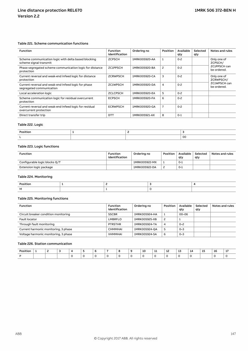
Table 221. Scheme communication functions
Function Functionidentification
Ordering no Position Availableqty
Selectedqty
Notes and rules
Scheme communication logic with delta based blockingscheme signal transmit
ZCPSCH 1MRK005920-AA 1 0-2 Only one ofZCPSCH/ZC1PPSCH canbe ordered.
Phase segregated scheme communication logic for distanceprotection
ZC1PPSCH 1MRK005920-BA 2 0-2
Current reversal and weak-end infeed logic for distanceprotection
ZCRWPSCH 1MRK005920-CA 3 0-2 Only one ofZCRWPSCH/ZC1WPSCH canbe ordered.
Current reversal and weak-end infeed logic for phasesegregated communication
ZC1WPSCH 1MRK005920-DA 4 0-2
Local acceleration logic ZCLCPSCH 1MRK005920-EA 5 0-2
Scheme communication logic for residual overcurrentprotection
ECPSCH 1MRK005920-FA 6 0-2
Current reversal and weak-end infeed logic for residualovercurrent protection
ECRWPSCH 1MRK005920-GA 7 0-2
Direct transfer trip DTT 1MRK005921-AX 8 0-1
Table 222. Logic
Position 1 2 3
L 00
Table 223. Logic functions
Function Functionidentification
Ordering no Position Availableqty
Selectedqty
Notes and rules
Configurable logic blocks Q/T 1MRK005922-MX 1 0-1
Extension logic package 1MRK005922-DA 2 0-1
Table 224. Monitoring
Position 1 2 3 4
M 1 0
Table 225. Monitoring functions
Function Functionidentification
Ordering no Position Availableqty
Selectedqty
Notes and rules
Circuit breaker condition monitoring SSCBR 1MRK005924-HA 1 00–06
Fault locator LMBRFLO 1MRK005925-XB 2 1
Through fault monitoring PTRSTHR 1MRK005924-TA 4 0–2
Current harmonic monitoring, 3 phase CHMMHAI 1MRK005924-QA 5 0–3
Voltage harmonic monitoring, 3 phase VHMMHAI 1MRK005924-SA 6 0–3
Table 226. Station communication
Position 1 2 3 4 5 6 7 8 9 10 11 12 13 14 15 16 17
P 0 0 0 0 0 0 0 0 0 0 0 0 0
Line distance protection REL670 1MRK 506 372-BEN HVersion 2.2
ABB 147© Copyright 2017 ABB. All rights reserved

Table 227. Station communication functions
Function Functionidentification
Ordering no Position Availableqty
Selectedqty
Notes and rules
IEC 61850-9-2 Process bus communication, 8 merging units 1MRK005933-HA 1 0-1
IEC 62439-3 Parallel redundancy protocol PRP 1MRK005932-FA 2 0-1 PRP or HSRrequire twoSFPs placed inpairs.
IEC 62439-3 High-availability seamless redundancy HSR 1MRK005932-NA 3 0-1
Synchrophasor report, 8 phasors 1MRK005933-DA 15 0-1 Thisfunctionalityrequiresaccurate timesynchronization,therefore either‘Precision TimeProtocol (PTP)Time synch orGTM or IRIG-Bwill be required.
Table 228. Language selection
Language Ordering no Selection Notes and rules
First local HMI user dialogue language
HMI language, English IEC 1MRK002930-AA B1
Additional local HMI user dialogue language
No additional HMI language X0 Additional 2nd languages arecontinuously being added.Please get in touch with localABB sales contact.
HMI language, English US 1MRK002920-UB A12
Selected B1
Table 229. Casing selection
Casing Ordering no Selection Notes and rules
1/2 x 19" rack casing, 1 TRM 1MRK000151-VA A
3/4 x 19" rack casing, 1 TRM 1MRK000151-VB B
3/4 x 19" rack casing, 2 TRM 1MRK000151-VE C
1/1 x 19" rack casing, 1 TRM 1MRK000151-VC D
1/1 x 19" rack casing, 2 TRM 1MRK000151-VD E
Selected
Table 230. Mounting selection
Mounting details with IP40 of protection from the front Ordering no Selection Notes and rules
No mounting kit included X
19" rack mounting kit for 1/2 x 19" case or 2xRHGS6 or RHGS12 1MRK002420-BB A
19" rack mounting kit for 3/4 x 19" case or 3xRHGS6 1MRK002420-BA B
19" rack mounting kit for 1/1 x 19" case 1MRK002420-CA C
Wall mounting kit 1MRK002420-DA D Wall mounting notrecommended withcommunication modules withfiber connection
Flush mounting kit 1MRK002420-PA E
Flush mounting kit + IP54 mounting seal 1MRK002420-NA F
Selected
Table 231. Power supply module selection
Power supply module Ordering no Selection Notes and rules
Compression terminals 1MRK002960-GA C
Ringlug terminals 1MRK002960-HA R
Power supply module 24-60 VDC 1MRK002239-AB A
Power supply module 90-250 VDC 1MRK002239-BB B
Selected
Line distance protection REL670 1MRK 506 372-BEN HVersion 2.2
148 ABB© Copyright 2017 ABB. All rights reserved

Table 232. Human machine interface selection
Human machine hardware interface Case size Ordering no Selection Notes and rules
Medium size - graphic display, IEC keypad symbols 1/2 x 19", IEC3/4 x 19”, IEC1/1 x 19”, IEC
1MRK000028-AA1MRK000028-CA1MRK000028-BA
B
Medium size - graphic display, ANSI keypad symbols 1/2 x 19", ANSI3/4 x 19”, ANSI1/1 x 19”, ANSI
1MRK000028-AB1MRK000028-CB1MRK000028-BB
C
Selected
Table 233. Analog system selection
Analog system Ordering no Selection Notes and rules
When more than one TRM is selected, the connector type on both TRMs must be the same (A compression or B ring lug).
Slot position (front view/rear view)
P40
/X40
1
P41/
X41
1
No Transformer input module included X0 X0 Only valid if IEC 61850-9-2Process bus communication isselected.
TRM 9I 1A + 3U 110/220V, 50/60Hz, compression terminals 1MRK002247-BG A3 A3
TRM 9I 5A + 3U 110/220V, 50/60Hz, compression terminals 1MRK002247-BH A4 A4
TRM 5I 1A + 4I 5A + 3U 110/220V, 50/60Hz, compression terminals 1MRK002247-BK A5 A5
TRM 6I 1A + 6U 110/220V, 50/60Hz, compression terminals 1MRK002247-AG A6 A6
TRM 6I 5A + 6U 110/220V, 50/60Hz, compression terminals 1MRK002247-AH A7 A7
TRM 6I 1A, 50/60Hz, compression terminals 1MRK002247-DG A8
TRM 6I 5A, 50/60Hz, compression terminals 1MRK002247-DH A9
TRM 7I 1A + 5U 110/220V, 50/60Hz, compression terminals 1MRK002247-AP A12 A12
TRM 7I 5A + 5U 110/220V, 50/60Hz, compression terminals 1MRK002247-AR A13 A13
TRM 6I 5A + 1I 1A + 5U 110/220V, 50/60Hz, compression terminals 1MRK002247-AU A14 A14
TRM 3I 5A + 4I 1A + 5U 110/220V, 50/60Hz, compression terminals 1MRK002247-AV A15 A15
TRM 3I 5A + 3I 1A + 6U 110/220V, 50/60Hz, compression terminals 1MRK002247-AE A16 A16
TRM 3IM 1A + 4IP 1A + 5U 110/220V, 50/60Hz, compression terminals 1MRK002247-EA A17 A17
TRM 3IM 5A + 4IP 5A + 5U 110/220V, 50/60Hz, compression terminals 1MRK002247-EB A18 A18
TRM 9I 1A + 3U 110/220V, 50/60Hz, ring lug terminals 1MRK002247-BC B3 B3
TRM 9I 5A + 3U 110/220V, 50/60Hz, ring lug terminals 1MRK002247-BD B4 B4
TRM 5I 1A + 4I 5A + 3U 110/220V, 50/60Hz, ring lug terminals 1MRK002247-BF B5 B5
TRM 6I 1A + 6U 110/220V, 50/60Hz, ring lug terminals 1MRK002247-AC B6 B6
TRM 6I 5A + 6U 110/220V, 50/60Hz, ring lug terminals 1MRK002247-AD B7 B7
TRM 6I 1A, 50/60Hz, ring lug terminals 1MRK002247-DC B8
TRM 6I 5A, 50/60Hz, ring lug terminals 1MRK002247-DD B9
TRM 7I 1A + 5U 110/220V, 50/60Hz, ring lug terminals 1MRK002247-AS B12 B12
TRM 7I 5A + 5U 110/220V, 50/60Hz, ring lug terminals 1MRK002247-AT B13 B13
TRM 6I 5A + 1I 1A + 5U 110/220V, 50/60Hz, ring lug terminals 1MRK002247-AX B14 B14
TRM 3I 5A + 4I 1A + 5U 110/220V, 50/60Hz, ring lug terminals 1MRK002247-AY B15 B15
TRM 3I 5A + 3I 1A + 6U 110/220V, 50/60Hz, ring lug terminals 1MRK002247-AF B16 B16
TRM 3IM 1A + 4IP 1A + 5U 110/220V, 50/60Hz, ring lug terminals 1MRK002247-EC B17 B17
TRM 3IM 5A + 4IP 5A + 5U 110/220V, 50/60Hz, ring lug terminals 1MRK002247-ED B18 B18
Selected
Line distance protection REL670 1MRK 506 372-BEN HVersion 2.2
ABB 149© Copyright 2017 ABB. All rights reserved

Table 234. Maximum quantity of I/O modules, with compression terminals
When ordering I/O modules, observe the maximum quantities according to the tables below. Note: Standard order of location for I/O modules is BIM-BOM-SOM-IOM-MIM from left to right as seen from the rear side of the IED, butcan also be freely placed.Note: The maximum quantity of I/O modules depends on the type of connection terminals.
Case sizes BIM IOM BOM/SOM
MIM Maximum in case
1/1 x 19” rack casing,one (1) TRM
14 6 4 4 14 *)
1/1 x 19” rack casing,two (2) TRM
11 6 4 4 11 *)
3/4 x 19” rack casing,one (1) TRM
8 6 4 4 8 *)
3/4 x 19” rack casing,two (2) TRM
5 5 4 4 5 *)
1/2 x 19” rack casing,one (1) TRM
3 3 3 1 3
*) including a combination of maximum four modules of type BOM, SOM and MIM
Table 235. Maximum quantity of I/O modules, with ringlug terminals
Note: Only every second slot can be used.
Case sizes BIM IOM BOM/SOM
MIM Maximum in case
1/1 x 19” rack casing,one (1) TRM
7 6 4 4 7 **) possible locations: P3, P5, P7, P9, P11, P13, P15
1/1 x 19” rack casing,two (2) TRM
5 5 4 4 5 **) possible locations: P3, P5, P7, P9, P11
3/4 x 19” rack casing,one (1) TRM
4 4 4 4 4 **) possible locations: P3, P5, P7, P9
3/4 x 19” rack casing,two (2) TRM
2 2 2 2 2, possible locations: P3, P5
1/2 x 19” rack casing,one (1) TRM
1 1 1 1 1, possible location: P3
**) including a combination of maximum four modules of type BOM, SOM and MIM
Line distance protection REL670 1MRK 506 372-BEN HVersion 2.2
150 ABB© Copyright 2017 ABB. All rights reserved

Table 236. Binary input/output module selection
Binary input/output modules
Ordering no Selection Notes and rules
Slot position(front view/rearview)
P3/X
31
P4/X
41
P5/X
51
P6/X
61
P7/X
71
P8/X
81
P9/X
91
P10
/X10
1
P11/
X11
1
P12/
X12
1
P13/
X13
1
P14/
X14
1
P15/
X15
1
P16/
X16
1
1/2 case with 1TRM
These black marksindicate the maximumnumber of modulesper casing type andthe slots that can beoccupied.
3/4 case with 1TRM
3/4 case with 2TRM
1/1 case with 1TRM
1/1 case with 2TRM
Compressionterminals
1MRK002960-KA C
Ringlugterminals
1MRK002960-LA R Only every second slotcan be used; see Table235
No board in slot X X X X X X X X X X X X X X
Binary outputmodule 24output relays(BOM)
1MRK000614-AB A A A A A A A A A A A A A A
BIM 16 inputs,RL24, 24-30VDC,50mA
1MRK000508-DD B1 B1 B1 B1 B1 B1 B1 B1 B1 B1 B1 B1 B1 B1
BIM 16 inputs,RL48, 48-60VDC,50mA
1MRK000508-AD C1 C1 C1 C1 C1 C1 C1 C1 C1 C1 C1 C1 C1 C1
BIM 16 inputs,RL110,110-125VDC,50mA
1MRK000508-BD D1 D1 D1 D1 D1 D1 D1 D1 D1 D1 D1 D1 D1 D1
BIM 16 inputs,RL220,220-250VDC,50mA
1MRK000508-CD E1 E1 E1 E1 E1 E1 E1 E1 E1 E1 E1 E1 E1 E1
BIM 16 inputs,RL220,220-250VDC,120mA
1MRK000508-CE E2 E2 E2 E2 E2 E2 E2 E2 E2 E2 E2 E2 E2 E2
BIM 16 inputs,RL24, 24-30VDC,50mA, enhancedpulse counting
1MRK000508-HA F F F F F F F F F F F F F F
BIM 16 inputs,RL48, 48-60VDC,50mA, enhancedpulse counting
1MRK000508-EA G G G G G G G G G G G G G G
BIM 16 inputs,RL110,110-125VDC,50mA, enhancedpulse counting
1MRK000508-FA H H H H H H H H H H H H H H
BIM 16 inputs,RL220,220-250VDC,50mA, enhancedpulse counting
1MRK000508-GA K K K K K K K K K K K K K K
IOM 8 inputs,10+2 outputs,RL24, 24-30VDC,50mA
1MRK000173-GD L1 L1 L1 L1 L1 L1 L1 L1 L1 L1 L1 L1 L1 L1
IOM 8 inputs,10+2 outputs,RL48, 48-60VDC,50mA
1MRK000173-AE M1 M1 M1 M1 M1 M1 M1 M1 M1 M1 M1 M1 M1 M1
Line distance protection REL670 1MRK 506 372-BEN HVersion 2.2
ABB 151© Copyright 2017 ABB. All rights reserved
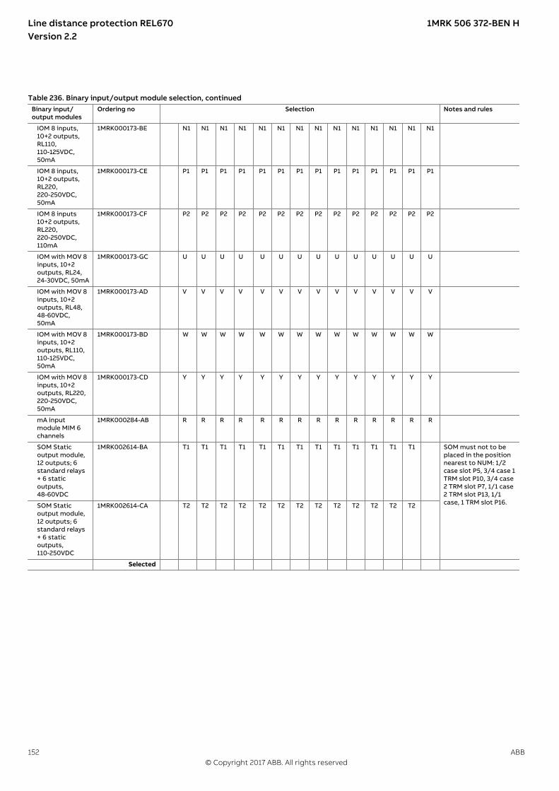
Table 236. Binary input/output module selection, continuedBinary input/output modules
Ordering no Selection Notes and rules
IOM 8 inputs,10+2 outputs,RL110,110-125VDC,50mA
1MRK000173-BE N1 N1 N1 N1 N1 N1 N1 N1 N1 N1 N1 N1 N1 N1
IOM 8 inputs,10+2 outputs,RL220,220-250VDC,50mA
1MRK000173-CE P1 P1 P1 P1 P1 P1 P1 P1 P1 P1 P1 P1 P1 P1
IOM 8 inputs10+2 outputs,RL220,220-250VDC,110mA
1MRK000173-CF P2 P2 P2 P2 P2 P2 P2 P2 P2 P2 P2 P2 P2 P2
IOM with MOV 8inputs, 10+2outputs, RL24,24-30VDC, 50mA
1MRK000173-GC U U U U U U U U U U U U U U
IOM with MOV 8inputs, 10+2outputs, RL48,48-60VDC,50mA
1MRK000173-AD V V V V V V V V V V V V V V
IOM with MOV 8inputs, 10+2outputs, RL110,110-125VDC,50mA
1MRK000173-BD W W W W W W W W W W W W W W
IOM with MOV 8inputs, 10+2outputs, RL220,220-250VDC,50mA
1MRK000173-CD Y Y Y Y Y Y Y Y Y Y Y Y Y Y
mA inputmodule MIM 6channels
1MRK000284-AB R R R R R R R R R R R R R R
SOM Staticoutput module,12 outputs; 6standard relays+ 6 staticoutputs,48-60VDC
1MRK002614-BA T1 T1 T1 T1 T1 T1 T1 T1 T1 T1 T1 T1 T1 SOM must not to beplaced in the positionnearest to NUM: 1/2case slot P5, 3/4 case 1TRM slot P10, 3/4 case2 TRM slot P7, 1/1 case2 TRM slot P13, 1/1case, 1 TRM slot P16. SOM Static
output module,12 outputs; 6standard relays+ 6 staticoutputs,110-250VDC
1MRK002614-CA T2 T2 T2 T2 T2 T2 T2 T2 T2 T2 T2 T2 T2
Selected
Line distance protection REL670 1MRK 506 372-BEN HVersion 2.2
152 ABB© Copyright 2017 ABB. All rights reserved
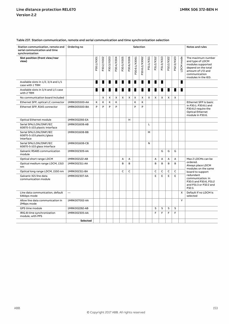
Table 237. Station communication, remote end serial communication and time synchronization selection
Station communication, remote endserial communication and timesynchronization
Ordering no Selection Notes and rules
Slot position (front view/rearview)
P30
:1/X
301
P30
:2/X
302
P30
:3/X
303
P30
:4/X
304
P30
:5/X
305
P30
:6/X
306
P30
:6:1
/X30
61
P30
:6:2
/X30
62
P31:
1/X
311
P31:
2/X
312
P31:
3/X
313
P32:
2/X
322
P32:
3/X
323
LDC
M m
od
e The maximum numberand type of LDCMmodules supporteddepend on the totalamount of I/O andcommunicationmodules in the IED.
Available slots in 1/2, 3/4 and 1/1case with 1 TRM
Available slots in 3/4 and 1/1 casewith 2 TRM
No communication board included X X X X X X X X X X X X
Ethernet SFP, optical LC connector 1MRK005500-AA K K K K K K Ethernet SFP is basicin P30:1. P30:6:1 andP30:6:2 require theOptical Ethernetmodule in P30:6.
Ethernet SFP, RJ45 connector 1MRK005500-BA P P P P P P
Optical Ethernet module 1MRK002266-EA H
Serial SPA/LON/DNP/IEC60870-5-103 plastic interface
1MRK001608-AB L
Serial SPA/LON/DNP/IEC60870-5-103 plastic/glassinterface
1MRK001608-BB M
Serial SPA/LON/DNP/IEC60870-5-103 glass interface
1MRK001608-CB N
Galvanic RS485 communicationmodule
1MRK002309-AA G G G
Optical short range LDCM 1MRK002122-AB A A A A A A Max 2 LDCMs can beordered.Always place LDCMmodules on the sameboard to supportredundantcommunication: inP30:5 and P30:6, P31:2and P31:3 or P32:2 andP32:3.
Optical medium range LDCM, 1310nm
1MRK002311-AA B B B B B B
Optical long range LDCM, 1550 nm 1MRK002311-BA C C C C C C
Galvanic X21 line datacommunication module
1MRK002307-AA E E E E
Line data communication, default64kbps mode
— X Default if no LDCM isselected
Allow line data communication in2Mbps mode
1MRK007002-AA Y
GPS time module 1MRK002282-AB S S S S
IRIG-B time synchronizationmodule, with PPS
1MRK002305-AA F F F F
Selected
Line distance protection REL670 1MRK 506 372-BEN HVersion 2.2
ABB 153© Copyright 2017 ABB. All rights reserved
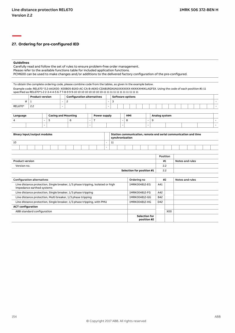
27. Ordering for pre-configured IEDGUID-B482FE4F-883D-4BE6-907B-4E823E21BBFC v14
GuidelinesCarefully read and follow the set of rules to ensure problem-free order management.Please refer to the available functions table for included application functions.PCM600 can be used to make changes and/or additions to the delivered factory configuration of the pre-configured.
To obtain the complete ordering code, please combine code from the tables, as given in the example below.
Example code: REL670 *2.2-A41X00- X00B05-B1X0-AC-CA-B-A6X0-CDAB1RGN1N1XXXXXXX-KKKKXHKKLAGFSX. Using the code of each position #1-11specified as REL670*1-2 2-3-4 4-5 6-7 7-8-9 9 9-10 10 10 10 10 10 10 10-11 11 11 11 11 11 11 11 11 11 11
Product version Configuration alternatives Software options
# 1 - 2 - 3 -
REL670* 2.2 - - -
Language Casing and Mounting Power supply HMI Analog system
4 - 5 6 - 7 - 8 - 9 -
- - - - -
Binary input/output modules Station communication, remote end serial communication and timesynchronization
10 - 11
-
Position
Product version #1 Notes and rules
Version no. 2.2
Selection for position #1 2.2
Configuration alternatives Ordering no #2 Notes and rules
Line distance protection, Single breaker, 1/3 phase tripping, isolated or highimpedance earthed systems
1MRK004812-EG A41
Line distance protection, Single breaker, 1/3 phase tripping 1MRK004812-FG A42
Line distance protection, Multi breaker, 1/3 phase tripping 1MRK004812-GG B42
Line distance protection, Single breaker, 1/3 phase tripping, with PMU 1MRK004812-HG D42
ACT configuration
ABB standard configuration X00
Selection forposition #2
Line distance protection REL670 1MRK 506 372-BEN HVersion 2.2
154 ABB© Copyright 2017 ABB. All rights reserved

Software options Ordering no #3 Notes and rules
No option X00 All fields in the ordering formdo not need to be filled in
High impedance differential protection - 3 blocks 1MRK004001-AB A02 Only for A42/B42/D42
Phase segregated scheme communication 1MRK004001-BE B05
Pole slip protection 1MRK004001-VU B24 Only for A42/B42/D42
Stub protection 1MRK004001-VK B27 Only for B42. One blockincluded as basic.
Sensitive directional residual overcurrent and power protection 1MRK004001-CT C16 Only for A42/B42/D42
Directional power protection 1MRK004001-VM C39 Only for A42/B42/D42
Overexcitation protection - 2 winding 1MRK004001-DC D03
Frequency protection - line 1MRK004001-ED E04 One block included as basic
General current and voltage protection 1MRK004001-FA F01 Only for A42/B42/D42
Fuse failure supervision based on voltage difference 1MRK004001-HC G03
Autorecloser - 1 circuit breaker 1MRK004001-GD H04 Only for A42/D42. One blockincluded as basic.
Autorecloser - 2 circuit breakers 1MRK004001-GE H05 Only for B42. Two blocksincluded as basic.
Control functionality for up to 10 objects 1MRK004001-GW H37 Only for A41/A42/D42
Control functionality for up to 15 objects 1MRK004001-GY H38 Only for B42
Through fault monitoring 1MRK004001-KR M22
Harmonic monitoring 1MRK004001-KS M23
IEC 62439-3 parallel redundancy protocol 1MRK004001-PP P23 Options P23 and P24 requiretwo SFPs placed in pairs. IEC 62439-3 High-availability seamless redundancy 1MRK004001-PR P24
IEC 61850-9-2 Process Bus communication, 8 merging units 1MRK004001-PT P30
Synchrophasor report, 8 phasors 1MRK004001-PV P32 This functionality requiresaccurate time synchronization,therefore either ‘Precision TimeProtocol (PTP) Time synch orGTM or IRIG-B will be required.Only for A41/A42/B42
Selection forposition #3
Language Ordering no #4 Notes and rules
First local HMI user dialogue language
HMI language, English IEC 1MRK002930-AA B1
Additional local HMI user dialogue language
No additional HMI language X0
HMI language, English US 1MRK002920-UB A12 Additional 2nd languages arecontinuously being added.Please get in touch with localABB sales contact.
Selection forposition #4
B1
Casing Ordering no #5 Notes and rules
1/2 x 19" rack casing, 1 TRM 1MRK000151-VA A
3/4 x 19" rack casing, 1 TRM 1MRK000151-VB B Only for A41
3/4 x 19” rack casing, 2 TRM 1MRK000151-VE C Only for A42/B42/D42
1/1 x 19" rack casing, 1 TRM 1MRK000151-VC D Only for A41
1/1 x 19" rack casing, 2 TRM 1MRK000151-VD E Only for A42/B42/D42
Selection forposition #5
Line distance protection REL670 1MRK 506 372-BEN HVersion 2.2
ABB 155© Copyright 2017 ABB. All rights reserved
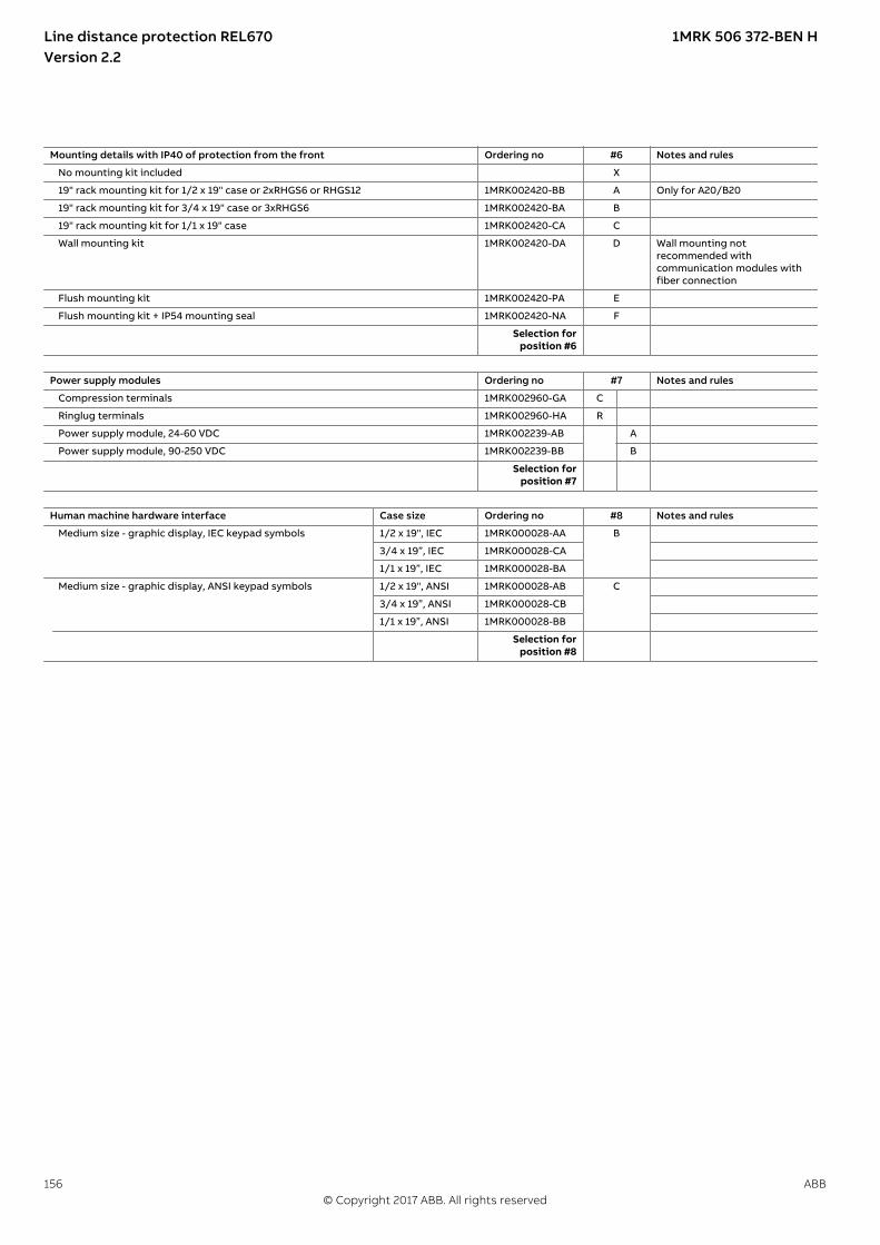
Mounting details with IP40 of protection from the front Ordering no #6 Notes and rules
No mounting kit included X
19" rack mounting kit for 1/2 x 19" case or 2xRHGS6 or RHGS12 1MRK002420-BB A Only for A20/B20
19" rack mounting kit for 3/4 x 19" case or 3xRHGS6 1MRK002420-BA B
19" rack mounting kit for 1/1 x 19" case 1MRK002420-CA C
Wall mounting kit 1MRK002420-DA D Wall mounting notrecommended withcommunication modules withfiber connection
Flush mounting kit 1MRK002420-PA E
Flush mounting kit + IP54 mounting seal 1MRK002420-NA F
Selection forposition #6
Power supply modules Ordering no #7 Notes and rules
Compression terminals 1MRK002960-GA C
Ringlug terminals 1MRK002960-HA R
Power supply module, 24-60 VDC 1MRK002239-AB A
Power supply module, 90-250 VDC 1MRK002239-BB B
Selection forposition #7
Human machine hardware interface Case size Ordering no #8 Notes and rules
Medium size - graphic display, IEC keypad symbols 1/2 x 19", IEC 1MRK000028-AA B
3/4 x 19”, IEC 1MRK000028-CA
1/1 x 19”, IEC 1MRK000028-BA
Medium size - graphic display, ANSI keypad symbols 1/2 x 19", ANSI 1MRK000028-AB C
3/4 x 19”, ANSI 1MRK000028-CB
1/1 x 19”, ANSI 1MRK000028-BB
Selection forposition #8
Line distance protection REL670 1MRK 506 372-BEN HVersion 2.2
156 ABB© Copyright 2017 ABB. All rights reserved

Analog system Ordering no #9 Notes and rules
When more than one TRM is selected, the connector type on both TRMs must be the same (A compression or B ring lug).
Slot position (front view/rear view)
P40
/X40
1
P41/
X41
1
No Transformer input module included X0 X0 Only valid if IEC 61850-9-2Process bus communication isselected.
TRM 9I 1A + 3U 110/220V, 50/60Hz, compression terminals 1MRK002247-BG A3 Only for A42/B42/D42
TRM 9I 5A + 3U 110/220V, 50/60Hz, compression terminals 1MRK002247-BH A4
TRM 5I 1A + 4I 5A + 3U 110/220V, 50/60Hz, compression terminals 1MRK002247-BK A5
TRM 6I 1A + 6U 110/220V, 50/60Hz, compression terminals 1MRK002247-AG A6 A6 Second TRM only forA42/B42/D42 TRM 6I 5A + 6U 110/220V, 50/60Hz, compression terminals 1MRK002247-AH A7 A7
TRM 6I 1A, 50/60Hz, compression terminals 1MRK002247-DG A8 Only for A42/B42/D42
TRM 6I 5A, 50/60Hz, compression terminals 1MRK002247-DH A9
TRM 7I 1A + 5U 110/220V, 50/60Hz, compression terminals 1MRK002247-AP A12
TRM 7I 5A + 5U 110/220V, 50/60Hz, compression terminals 1MRK002247-AR A13
TRM 3I 5A + 3I 1A + 6U 110/220V, 50/60Hz, compression terminals 1MRK002247-AE A16 A16 As a first TRM, only forA41/A42/D42; as a second TRMonly for A42/D42
TRM 9I 1A + 3U 110/220V, 50/60Hz, ring lug terminals 1MRK002247-BC B3 Only for A42/B42/D42
TRM 9I 5A + 3U 110/220V, 50/60Hz, ring lug terminals 1MRK002247-BD B4
TRM 5I 1A + 4I 5A + 3U 110/220V, 50/60Hz, ring lug terminals 1MRK002247-BF B5
TRM 6I 1A + 6U 110/220V, 50/60Hz, ring lug terminals 1MRK002247-AC B6 B6
TRM 6I 5A + 6U 110/220V, 50/60Hz, ring lug terminals 1MRK002247-AD B7 B7
TRM 6I 1A, 50/60Hz, ring lug terminals 1MRK002247-DC B8
TRM 6I 5A, 50/60Hz, ring lug terminals 1MRK002247-DD B9
TRM 7I 1A + 5U 110/220V, 50/60Hz, ring lug terminals 1MRK002247-AS B12
TRM 7I 5A + 5U 110/220V, 50/60Hz, ring lug terminals 1MRK002247-AT B13
TRM 3I 5A + 3I 1A + 6U 110/220V, 50/60Hz, ring lug terminals 1MRK002247-AF B16 B16 Only for A42/D42
Selection forposition #9
Line distance protection REL670 1MRK 506 372-BEN HVersion 2.2
ABB 157© Copyright 2017 ABB. All rights reserved

Binary input/output modules
Ordering no #10 Notes and rules
For pulse counting, for example kWh metering, the BIM with enhanced pulse counting capabilities must be used.
1 BIM and 1 BOM required in positions P3 and P4 in REL A42, B42 and D42. B42 requires one extra BIM in position P5. 1 IOM requiredin position P3 in A41.
Slot position(front view/rearview)
P3/X
31
P4/X
41
P5/X
51
P6/X
61
P7/X
71
P8/X
81
P9/X
91
P10
/X10
1
P11/
X11
1
P12/
X12
1
P13/
X13
1
P14/
X14
1
P15/
X15
1
P16/
X16
1
1/2 case with 1TRM
These black marksindicate the maximumnumber of modulesper casing type andthe slots that can beoccupied.
3/4 case with 1TRM
3/4 case with 2TRM
1/1 case with 1TRM
1/1 case with 2TRM
Compressionterminals
1MRK002960-KA C
No board in slot X X X X X X X X X X X X X
Binary outputmodule 24output relays(BOM)
1MRK000614-AB A A A A A A A A A A A A A Maximum 4 (BOM+SOM+MIM) boards
BIM 16 inputs,RL24, 24-30VDC,50mA
1MRK000508-DD B1 B1 B1 B1 B1 B1 B1 B1 B1 B1 B1 B1 B1 B1
BIM 16 inputs,RL48, 48-60VDC,50mA
1MRK000508-AD C1 C1 C1 C1 C1 C1 C1 C1 C1 C1 C1 C1 C1 C1
BIM 16 inputs,RL110,110-125VDC,50mA
1MRK000508-BD D1 D1 D1 D1 D1 D1 D1 D1 D1 D1 D1 D1 D1 D1
BIM 16 inputs,RL220,220-250VDC,50mA
1MRK000508-CD E1 E1 E1 E1 E1 E1 E1 E1 E1 E1 E1 E1 E1 E1
BIM 16 inputs,RL220,220-250VDC,120mA
1MRK000508-CE E2 E2 E2 E2 E2 E2 E2 E2 E2 E2 E2 E2 E2 E2
BIM 16 inputs,RL24, 24-30VDC,50mA, enhancedpulse counting
1MRK000508-HA F F F F F F F F F F F F F
BIM 16 inputs,RL48, 48-60VDC,50mA, enhancedpulse counting
1MRK000508-EA G G G G G G G G G G G G G
BIM 16 inputs,RL110,110-125VDC,50mA, enhancedpulse counting
1MRK000508-FA H H H H H H H H H H H H H
BIM 16 inputs,RL220,220-250VDC,50mA, enhancedpulse counting
1MRK000508-GA K K K K K K K K K K K K K
IOM 8 inputs,10+2 outputs,RL24, 24-30VDC,50mA
1MRK000173-GD L1 L1 L1 L1 L1 L1 L1 L1 L1 L1 L1 L1 L1 L1
Line distance protection REL670 1MRK 506 372-BEN HVersion 2.2
158 ABB© Copyright 2017 ABB. All rights reserved
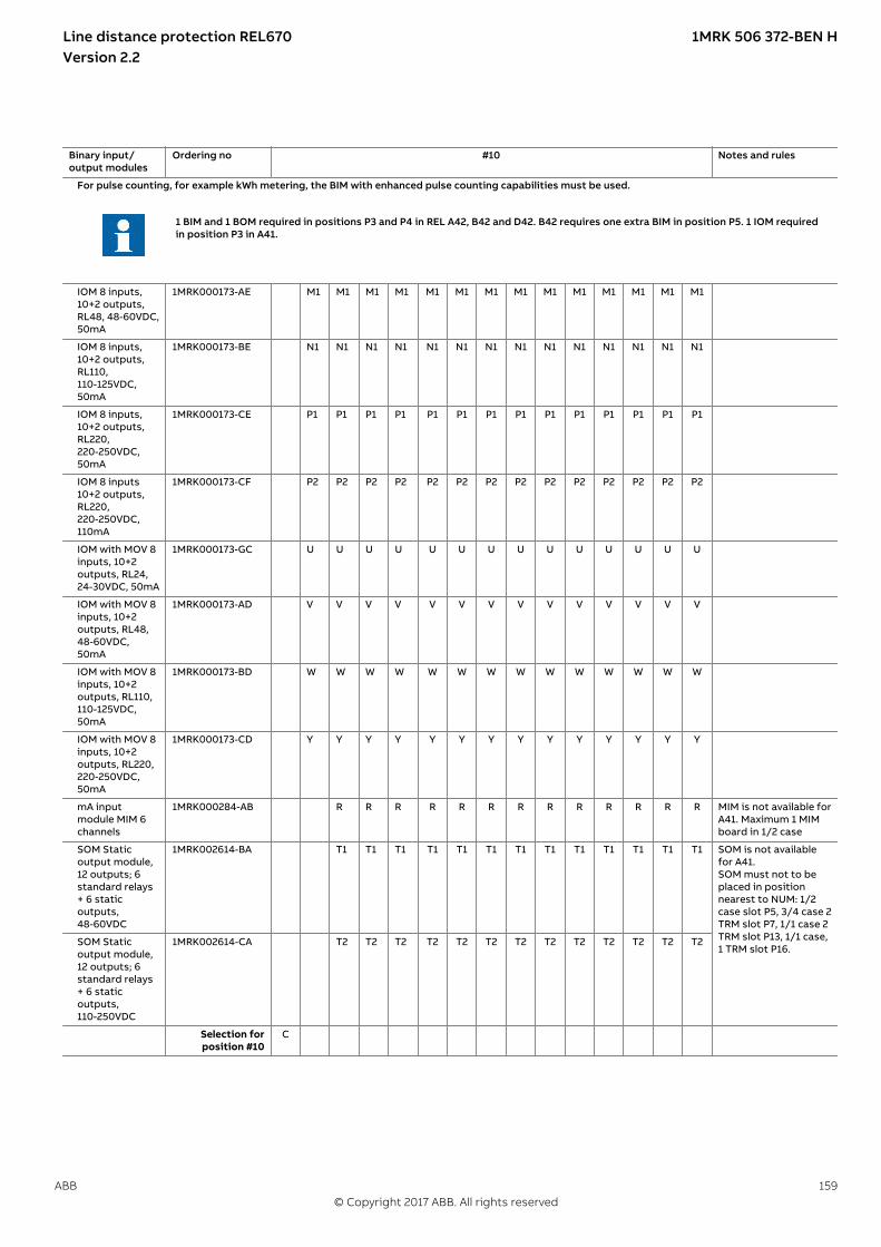
Binary input/output modules
Ordering no #10 Notes and rules
For pulse counting, for example kWh metering, the BIM with enhanced pulse counting capabilities must be used.
1 BIM and 1 BOM required in positions P3 and P4 in REL A42, B42 and D42. B42 requires one extra BIM in position P5. 1 IOM requiredin position P3 in A41.
IOM 8 inputs,10+2 outputs,RL48, 48-60VDC,50mA
1MRK000173-AE M1 M1 M1 M1 M1 M1 M1 M1 M1 M1 M1 M1 M1 M1
IOM 8 inputs,10+2 outputs,RL110,110-125VDC,50mA
1MRK000173-BE N1 N1 N1 N1 N1 N1 N1 N1 N1 N1 N1 N1 N1 N1
IOM 8 inputs,10+2 outputs,RL220,220-250VDC,50mA
1MRK000173-CE P1 P1 P1 P1 P1 P1 P1 P1 P1 P1 P1 P1 P1 P1
IOM 8 inputs10+2 outputs,RL220,220-250VDC,110mA
1MRK000173-CF P2 P2 P2 P2 P2 P2 P2 P2 P2 P2 P2 P2 P2 P2
IOM with MOV 8inputs, 10+2outputs, RL24,24-30VDC, 50mA
1MRK000173-GC U U U U U U U U U U U U U U
IOM with MOV 8inputs, 10+2outputs, RL48,48-60VDC,50mA
1MRK000173-AD V V V V V V V V V V V V V V
IOM with MOV 8inputs, 10+2outputs, RL110,110-125VDC,50mA
1MRK000173-BD W W W W W W W W W W W W W W
IOM with MOV 8inputs, 10+2outputs, RL220,220-250VDC,50mA
1MRK000173-CD Y Y Y Y Y Y Y Y Y Y Y Y Y Y
mA inputmodule MIM 6channels
1MRK000284-AB R R R R R R R R R R R R R MIM is not available forA41. Maximum 1 MIMboard in 1/2 case
SOM Staticoutput module,12 outputs; 6standard relays+ 6 staticoutputs,48-60VDC
1MRK002614-BA T1 T1 T1 T1 T1 T1 T1 T1 T1 T1 T1 T1 T1 SOM is not availablefor A41.SOM must not to beplaced in positionnearest to NUM: 1/2case slot P5, 3/4 case 2TRM slot P7, 1/1 case 2TRM slot P13, 1/1 case,1 TRM slot P16.
SOM Staticoutput module,12 outputs; 6standard relays+ 6 staticoutputs,110-250VDC
1MRK002614-CA T2 T2 T2 T2 T2 T2 T2 T2 T2 T2 T2 T2 T2
Selection forposition #10
C
Line distance protection REL670 1MRK 506 372-BEN HVersion 2.2
ABB 159© Copyright 2017 ABB. All rights reserved
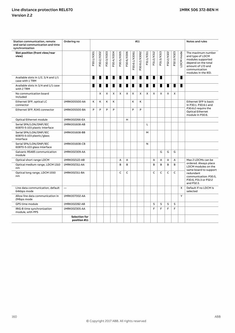
Station communication, remoteend serial communication and timesynchronization
Ordering no #11 Notes and rules
Slot position (front view/rearview)
P30
:1/X
301
P30
:2/X
302
P30
:3/X
303
P30
:4/X
304
P30
:5/X
305
P30
:6/X
306
P30
:6:1
/X30
61
P30
:6:2
/X30
62
P31:
1/X
311
P31:
2/X
312
P31:
3/X
313
P32:
2/X
322
P32:
3/X
323
LDC
M m
od
e The maximum numberand type of LDCMmodules supporteddepend on the totalamount of I/O andcommunicationmodules in the IED.
Available slots in 1/2, 3/4 and 1/1case with 1 TRM
Available slots in 3/4 and 1/1 casewith 2 TRM
No communication boardincluded
X X X X X X X X X X X X
Ethernet SFP, optical LCconnector
1MRK005500-AA K K K K K K Ethernet SFP is basicin P30:1. P30:6:1 andP30:6:2 require theOptical Ethernetmodule in P30:6.
Ethernet SFP, RJ45 connector 1MRK005500-BA P P P P P P
Optical Ethernet module 1MRK002266-EA H
Serial SPA/LON/DNP/IEC60870-5-103 plastic interface
1MRK001608-AB L
Serial SPA/LON/DNP/IEC60870-5-103 plastic/glassinterface
1MRK001608-BB M
Serial SPA/LON/DNP/IEC60870-5-103 glass interface
1MRK001608-CB N
Galvanic RS485 communicationmodule
1MRK002309-AA G G G
Optical short range LDCM 1MRK002122-AB A A A A A A Max 2 LDCMs can beordered. Always placeLDCM modules on thesame board to supportredundantcommunication: P30:5,P30:6, P31:3 or P32:2and P32:3.
Optical medium range, LDCM 1310nm
1MRK002311-AA B B B B B B
Optical long range, LDCM 1550nm
1MRK002311-BA C C C C C C
Line data communication, default64kbps mode
— X Default if no LDCM isselected
Allow line data communication in2Mbps mode
1MRK007002-AA Y
GPS time module 1MRK002282-AB S S S S
IRIG-B time synchronizationmodule, with PPS
1MRK002305-AA F F F F
Selection forposition #11
Line distance protection REL670 1MRK 506 372-BEN HVersion 2.2
160 ABB© Copyright 2017 ABB. All rights reserved

28. Ordering for Accessories
AccessoriesIP15151-1 v1
GPS antenna and mounting detailsM12374-3 v5
GPS antenna, including mounting kits Quantity: 1MRK 001 640-AA
Cable for antenna, 20 m (Appx. 65 ft) Quantity: 1MRK 001 665-AA
Cable for antenna, 40 m (Appx. 131 ft) Quantity: 1MRK 001 665-BA
Interface converter (for remote end data communication)M16668-3 v9
External interface converter from C37.94 (64kbps) to G703 Quantity:
1 2 1MRK 002 245-AA
External interface converter from C37.94 (64kbps/2Mbps) to G703.E1 Quantity:
1 2 1MRK 002 245-BA
Test switchSEMOD111888-5 v12
The test system COMBITEST intended for use with theIEDs is described in 1MRK 512 001-BEN and 1MRK001024-CA. Please refer to the website:www.abb.com/protection-control for detailedinformation.
Due to the high flexibility of our product and the widevariety of applications possible the test switches needsto be selected for each specific application.
Select your suitable test switch base on the availablecontacts arrangements shown in the referencedocumentation.
However our proposals for suitable variants are;
Single breaker/Single or Three Phase trip with internalneutral on current circuits (ordering number RK926 315-AK).
Single breaker/Single or Three Phase trip with externalneutral on current circuits (ordering number RK926 315-AC).
Multi-breaker/Single or Three Phase trip with internalneutral on current circuits (ordering number RK926 315-BE).
Multi-breaker/Single or Three Phase trip with externalneutral on current circuit (ordering number RK926 315-BV).
The normally open "In test mode" contact 29-30 on theRTXP test switches should be connected to the input ofthe test function block to allow activation of functionsindividually during testing.
Test switches type RTXP 24 is ordered separately. Pleaserefer to Section Related documents for references tocorresponding documents.
RHGS 6 Case or RHGS 12 Case with mounted RTXP 24and the on/off switch for dc-supply are orderedseparately. Please refer to Section Related documentsfor references to corresponding documents.
Line distance protection REL670 1MRK 506 372-BEN HVersion 2.2
ABB 161© Copyright 2017 ABB. All rights reserved

Protection coverM15040-3 v7
Protective cover for rear side of RHGS6, 6U, 1/4 x 19” Quantity: 1MRK 002 420-AE
Protective cover for rear side of terminal, 6U, 1/2 x 19” Quantity: 1MRK 002 420-TA
Protective cover for rear side of terminal, 6U, 3/4 x 19” Quantity: 1MRK 002 420-SA
Protective cover for rear side of terminal, 6U, 1/1 x 19” Quantity: 1MRK 002 420-RA
External resistor unitSEMOD120228-4 v8
High impedance resistor unit with resistor and voltage dependent resistor 20-100V,1ph
Quantity:
1 2 3 RK 795 101-MA
High impedance resistor unit with resistor and voltage dependent resistor 20-100V,3ph
Quantity:
RK 795 101-MB
High impedance resistor unit with resistor and voltage dependent resistor100-400V, 1ph
Quantity:
1 2 3 RK 795 101-CB
High impedance resistor unit with resistor and voltage dependent resistor100-400V, 3ph
Quantity:
RK 795 101-DC
CombiflexIP15161-1 v1
Key switch for settingsSEMOD130356-4 v7
Key switch for lock-out of settings via LHMI Quantity: 1MRK 000 611-A
Note: To connect the key switch, leads with 10 A Combiflex socket on one end must be used.SEMOD130267-5 v8
Mounting kit
Side-by-side mounting kit Quantity: 1MRK 002 420-Z
Configuration and monitoring toolsIP15162-1 v2M15042-3 v5
Front connection cable between LHMI and PC Quantity: 1MRK 001 665-CA
SEMOD131414-4 v4
LED Label special paper A4, 1 pc Quantity: 1MRK 002 038-CA
LED Label special paper Letter, 1 pc Quantity: 1MRK 002 038-DA
ManualsM15161-3 v15
Note: One (1) IED Connect USB flash drive containing user documentation (Operation manual,Technical manual, Installation manual, Commissioning manual, Application manual and Gettingstarted guide), Connectivity packages and LED label template is always included for each IED.
Line distance protection REL670 1MRK 506 372-BEN HVersion 2.2
162 ABB© Copyright 2017 ABB. All rights reserved

Rule: Specify additional quantity of IED Connect USB flash drive requested. Quantity: 1MRK 002 290-AE
Line distance protection REL670 1MRK 506 372-BEN HVersion 2.2
ABB 163© Copyright 2017 ABB. All rights reserved
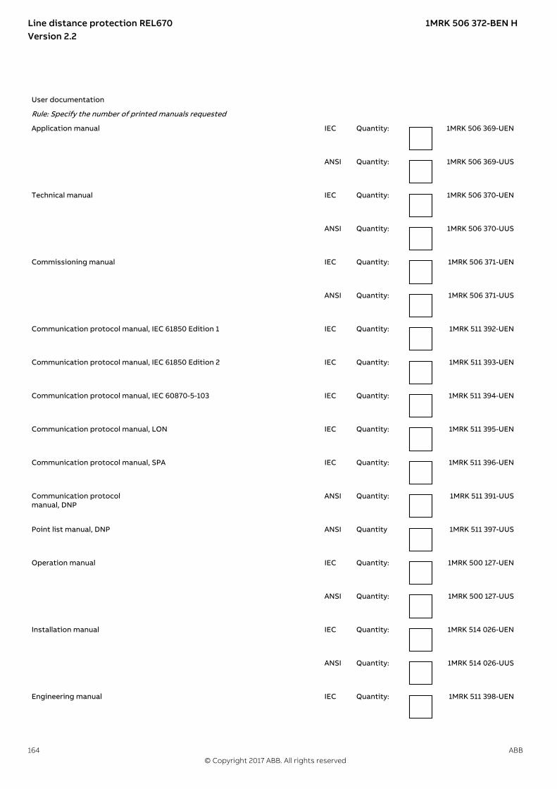
User documentation
Rule: Specify the number of printed manuals requested
Application manual IEC Quantity: 1MRK 506 369-UEN
ANSI Quantity: 1MRK 506 369-UUS
Technical manual IEC Quantity: 1MRK 506 370-UEN
ANSI Quantity: 1MRK 506 370-UUS
Commissioning manual IEC Quantity: 1MRK 506 371-UEN
ANSI Quantity: 1MRK 506 371-UUS
Communication protocol manual, IEC 61850 Edition 1
IEC Quantity: 1MRK 511 392-UEN
Communication protocol manual, IEC 61850 Edition 2 IEC Quantity: 1MRK 511 393-UEN
Communication protocol manual, IEC 60870-5-103 IEC Quantity: 1MRK 511 394-UEN
Communication protocol manual, LON IEC Quantity: 1MRK 511 395-UEN
Communication protocol manual, SPA IEC Quantity: 1MRK 511 396-UEN
Communication protocolmanual, DNP
ANSI Quantity: 1MRK 511 391-UUS
Point list manual, DNP ANSI Quantity 1MRK 511 397-UUS
Operation manual IEC Quantity: 1MRK 500 127-UEN
ANSI Quantity: 1MRK 500 127-UUS
Installation manual IEC Quantity: 1MRK 514 026-UEN
ANSI Quantity: 1MRK 514 026-UUS
Engineering manual IEC Quantity: 1MRK 511 398-UEN
Line distance protection REL670 1MRK 506 372-BEN HVersion 2.2
164 ABB© Copyright 2017 ABB. All rights reserved

ANSI Quantity: 1MRK 511 398-UUS
Cyber security deployment guideline IEC Quantity: 1MRK 511 399-UEN
Application guide, Communication set-up IEC Quantity: 1MRK 505 382-UEN
Reference informationM2175-3 v4
For our reference and statistics we would be pleased to be provided with the following application data:
Country: End user:
Station name: Voltage level: kV
Related documentsGUID-94E8A5CA-BE1B-45AF-81E7-5A41D34EE112 v7
Documents related to REL670 Document numbers
Application manual IEC:1MRK 506 369-UENANSI:1MRK 506 369-UUS
Commissioning manual IEC:1MRK 506 371-UENANSI:1MRK 506 371-UUS
Product guide 1MRK 506 372-BEN
Technical manual IEC:1MRK 506 370-UENANSI:1MRK 506 370-UUS
Type test certificate IEC:1MRK 506 372-TENANSI:1MRK 506 372-TUS
670 series manuals Document numbers
Operation manual IEC:1MRK 500 127-UENANSI:1MRK 500 127-UUS
Engineering manual IEC:1MRK 511 398-UENANSI:1MRK 511 398-UUS
Installation manual IEC:1MRK 514 026-UENANSI:1MRK 514 026-UUS
Communication protocolmanual, DNP3
1MRK 511 391-UUS
Communication protocolmanual, IEC 60870-5-103
1MRK 511 394-UEN
Communication protocolmanual, IEC 61850 Edition 1
1MRK 511 392-UEN
Communication protocolmanual, IEC 61850 Edition 2
1MRK 511 393-UEN
Communication protocolmanual, LON
1MRK 511 395-UEN
Communication protocolmanual, SPA
1MRK 511 396-UEN
Point list manual, DNP3 1MRK 511 397-UUS
Accessories guide IEC:1MRK 514 012-BENANSI:1MRK 514 012-BUS
Cyber security deploymentguideline
1MRK 511 399-UEN
Connection and Installationcomponents
1MRK 513 003-BEN
Test system, COMBITEST 1MRK 512 001-BEN
Application guide,Communication set-up
1MRK 505 382-UEN
Line distance protection REL670 1MRK 506 372-BEN HVersion 2.2
ABB 165© Copyright 2017 ABB. All rights reserved

166

ABB ABGrid Automation ProductsSE-721 59 Västerås, SwedenPhone +46 (0) 21 32 50 00
www.abb.com/protection-control
© Copyright 2017 ABB.All rights reserved.
Scan this QR code to visit our website
1MR
K 5
06
372-
BE
N