
Line distance protection REL670 2.1 IEC Product guide · Line distance protection REL670 2.1 IEC...
132
Relion ® 670 series Line distance protection REL670 2.1 IEC Product guide
Transcript of Line distance protection REL670 2.1 IEC Product guide · Line distance protection REL670 2.1 IEC...
Relion® 670 series
Line distance protection REL670 2.1 IECProduct guide
Contents
1. Application..................................................................... 3
2. Available functions........................................................11
3. Differential protection....................................................22
4. Impedance protection.................................................. 23
5. Current protection........................................................ 28
6. Voltage protection........................................................ 30
7. Frequency protection....................................................31
8. Multipurpose protection................................................31
9. Secondary system supervision..................................... 31
10. Control........................................................................ 32
11. Scheme communication..............................................34
12. Logic...........................................................................36
13. Monitoring...................................................................38
14. Metering......................................................................40
15. Human machine interface............................................41
16. Basic IED functions..................................................... 41
17. Station communication ...............................................41
18. Remote communication.............................................. 42
19. Hardware description.................................................. 42
20. Connection diagrams.................................................. 45
21. Technical data.............................................................46
22. Ordering for customized IED......................................113
23. Ordering for pre-configured IED.................................122
24. Ordering for Accessories........................................... 127
Disclaimer
The information in this document is subject to change without notice and should not be construed as a commitment by ABB. ABB assumes no responsibility for any errors
that may appear in this document. Drawings and diagrams are not binding.
© Copyright 2015 ABB.
All rights reserved.
Trademarks
ABB and Relion are registered trademarks of the ABB Group. All other brand or product names mentioned in this document may be trademarks or registered trademarks
of their respective holders.
1MRK 506 356-BEN -Line distance protection REL670 2.1 IEC Product version: 2.1
2 ABB

1. ApplicationDistance protection with quadrilateral or mho characteristics isavailable. The full scheme distance protection providesprotection of power lines with high sensitivity and lowrequirement on remote end communication. The six zones havefully independent measuring and setting which gives highflexibility for all types of lines. Load encroachment and adaptivereach compensation are included.
The modern technical solution offers fast operating time oftypically less than one cycle.
The IED also includes an alternative for use on impedanceearthed or isolated networks. It includes phase preference logicto select and trip only one line at cross-country faults.
The autorecloser for single-, two-, and/or three-phase trippingand autoreclosing includes priority features for multi-breakerarrangements. It co-operates with the synchrocheck functionwith high-speed or delayed reclosing.
A high impedance differential protection can be used to protectT-feeders or line reactors.
High set instantaneous phase and earth overcurrent, four stepdirectional or non-directional delayed phase and earthovercurrent, sensitive earth fault for not direct earthed systems,thermal overload and two step under and overvoltageprotection are examples of the available functions allowing theuser to fulfill any application requirement.
The distance phase and earth fault protection, and thedirectional earth overcurrent protection can communicate withremote end in any teleprotection communication scheme. Withthe included remote communication, following the IEEE C37.94standard, 6 x 32 channels for intertrip and binary signals areavailable per LDCM communication module in thecommunication between the IEDs.
The IED can also be provided with full bay control andinterlocking functionality including co-operation with thesynchrocheck function to allow integration of the main or back-up control.
Out of Step function is available to separate power systemsections close to electrical centre at occurring out of step.
The IED can be used in applications with IEC 61850-9-2LEprocess bus with up to six merging units (MU) depending onother functionality included in the IED. Each MU has eightanalogue channels, normally four currents and four voltages.Conventional and Merging Unit channels can be mixed freely inthe application.
Logic is prepared with a graphical tool. The advanced logiccapability allows special applications such as automatic
opening of disconnectors in multi-breaker arrangements,closing of breaker rings, load transfer logics and so on. Thegraphical configuration tool with delay mode, ensures simpleand fast testing and commissioning.
Disturbance recorder and fault locator are available to allowindependent post-fault analysis after primary disturbances.
Forcing of binary inputs and outputs is a convenient way to testwiring in substations as well as testing configuration logic in theIEDs. Basically it means that all binary inputs and outputs on theIED I/O modules (BOM, BIM, IOM & SOM) can be forced toarbitrary values.
Central Account Management is an authenticationinfrastructure that offers a secure solution for enforcing accesscontrol to IEDs and other systems within a substation. Thisincorporates management of user accounts, roles andcertificates and the distribution of such, a procedure completelytransparent to the user.
Flexible Product Naming allows the customer to use an IED-vendor independent 61850 model of the IED. This customermodel will be used as the IEC 61850 data model, but all otheraspects of the IED will remain unchanged (e.g., names on thelocal HMI and names in the tools). This offers significantflexibility to adapt the IED to the customers system andstandard solution
Communication via optical connections ensures immunityagainst disturbances.
Five packages have been defined for following applications:
• Single-breaker (double or single bus) with three phasetripping for high ohmic and resonance earthed systems(A21)
• Single-breaker (double or single bus) with three phasetripping (A31)
• Single-breaker (double or single bus) with single phasetripping (A32)
• Multi-breaker (one-and a half or ring) with three phasetripping (B31)
• Multi-breaker (one-and a half or ring) with single phasetripping (B32)
Optional functions are not configured but a maximumconfiguration with all optional functions are available astemplate in the graphical configuration tool. Analog inputs andbinary input/output signals are pre-defined for basic use. Othersignals may be required by each particular application.
Add binary I/O boards as required for the application whenordering.
1MRK 506 356-BEN -Line distance protection REL670 2.1 IEC Product version: 2.1 Issued: December 2015
Revision: -
ABB 3
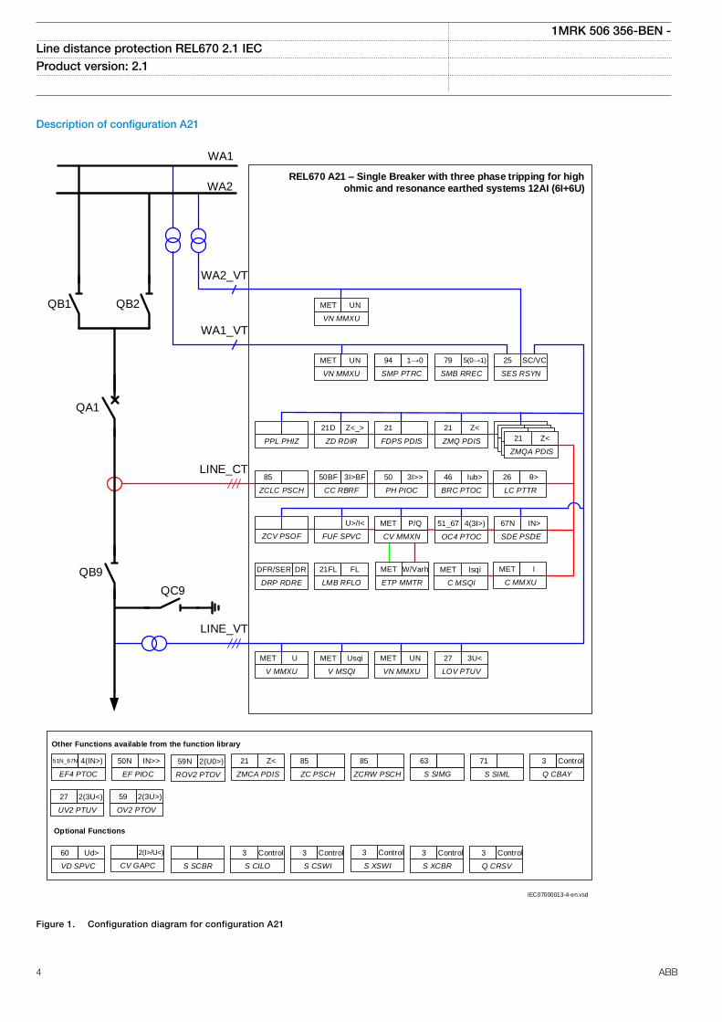
Description of configuration A21
QB1 QB2
QA1
QB9
QC9
WA1
WA2REL670 A21 – Single Breaker with three phase tripping for high
ohmic and resonance earthed systems 12AI (6I+6U)
ZCLC PSCH
85
67N
SDE PSDE
IN>
OC4 PTOC
51_67 4(3I>)
LC PTTR
26 θ>
BRC PTOC
46 Iub>
PH PIOC
50 3I>>
CC RBRF
50BF 3I>BF
Other Functions available from the function library
ROV2 PTOV
59N 2(U0>)
EF4 PTOC
51N_67N 4(IN>)
EF PIOC
50N IN>>
ZMCA PDIS
21 Z<
VN MMXU
MET UN
VN MMXU
MET UN
Optional Functions
S SIMG
63
ZC PSCH
85
ZCRW PSCH
85
S SIML
71
Q CBAY
3 Control
WA2_VT
WA1_VT
LINE_CT
LINE_VT
SMP PTRC
94 1->0
SMB RREC
79 5(0→1)
SMP PTRC
94 1→0
SES RSYN
25 SC/VC
ZCV PSOF
LOV PTUV
27 3U<
V MSQI
MET Usqi
VN MMXU
MET UN
DRP RDRE
DFR/SER DR
V MMXU
MET U
LMB RFLO
21FL FL
PPL PHIZ ZD RDIR
21D Z<_>
FDPS PDIS
21
ZMQ PDIS
21 Z<
ZMQ PDIS
21 3Z<
ZMQ PDIS
21 3Z<
ZMQ PDIS
21 3Z<
ZMQA PDIS
21 Z<
FUF SPVC
U>/I<
C MMXU
MET I
C MSQI
MET Isqi
CV MMXN
MET P/Q
ETP MMTR
MET W/Varh
S CILO
3 Control
S CSWI
3 Control
S SCBR
VD SPVC
60 Ud>
CV GAPC
2(I>/U<)
S XCBR
3 Control
Q CRSV
3 Control
S XSWI
3 Control
UV2 PTUV
27 2(3U<)
OV2 PTOV
59 2(3U>)
IEC07000013-4-en.vsd
IEC07000013 V4 EN
Figure 1. Configuration diagram for configuration A21
1MRK 506 356-BEN -Line distance protection REL670 2.1 IEC Product version: 2.1
4 ABB
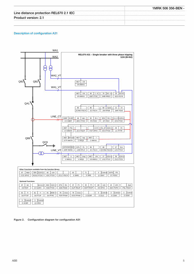
Description of configuration A31
QB1 QB2
QA1
QB9
QC9
WA1
WA2REL670 A31 – Single breaker with three phase tripping
12AI (6I+6U)
CC RBRF
50BF 3I>BF
26
LC PTTR
θ>
OC4 PTOC
51_67 4(3I>)
EF4 PTOC
51N_67N 4(IN>)
EF PIOC
50N IN>>
PH PIOC
50 3I>>
BRC PTOC
46 Iub>
Other Functions available from the function library
CC PDSC
52PD PD
S CILO
3 Control
S CSWI
3 Control
ROV2 PTOV
59N 2(U0>)
CCS SPVC
87 INd/I
VDC PTOV
60 Ud>
NS4 PTOC
46I2 4(I2>)
HZ PDIF
87 Id>
CV GAPC
2(I>/U<)
VN MMXU
MET UN
VN MMXU
MET UN
Optional Functions
S SIMG
63
ZCLC PSCH S SIML
71
Q CBAY
3 Control
Q CRSV
3 Control
S XCBR
3 Control
S XSWI
3 Control
WA2_VT
WA1_VT
LINE_CT
LINE_VT
SMP PTRC
94 1->0
SMB RREC
79 5(0→1)
SMP PTRC
94 1→0
SES RSYN
25 SC/VC
UV2 PTUV
27 2(3U<)
V MSQI
MET Usqi
VN MMXU
MET UN
V MMXU
MET U
LMB RFLO
21FL FL
EC PSCH
85
ZCRW PSCH
85
ZC PSCH
85
ZM RPSB
68 Zpsb
ZMF PDIS
21 Z<
ZCV PSOF FUF SPVC
U>/I<
SDE PSDE
67N IN>
GUP PDUP
37 P<
PSL PSCH
Zpsl
VD SPVC
60 Ud>
OEX PVPH
24 U/f>
GOP PDOP
32 P>
SA PFRC
81 df/dt<>
SA PTOF
81 f>
SA PTUF
81 f>
PSP PPAM
78 Ucos
OOS PPAM
78 Ucos
S SCBR
DRP RDRE
DFR/SER DR
OV2 PTOV
59 2(3U>)
ECRW PSCH
85
LOV PTUV
27 3U<
C MMXU
MET I
C MSQI
MET Isqi
ETP MMTR
MET W/Varh
CV MMXN
MET P/Q
IEC05000846 V4 EN
Figure 2. Configuration diagram for configuration A31
1MRK 506 356-BEN -Line distance protection REL670 2.1 IEC Product version: 2.1
ABB 5
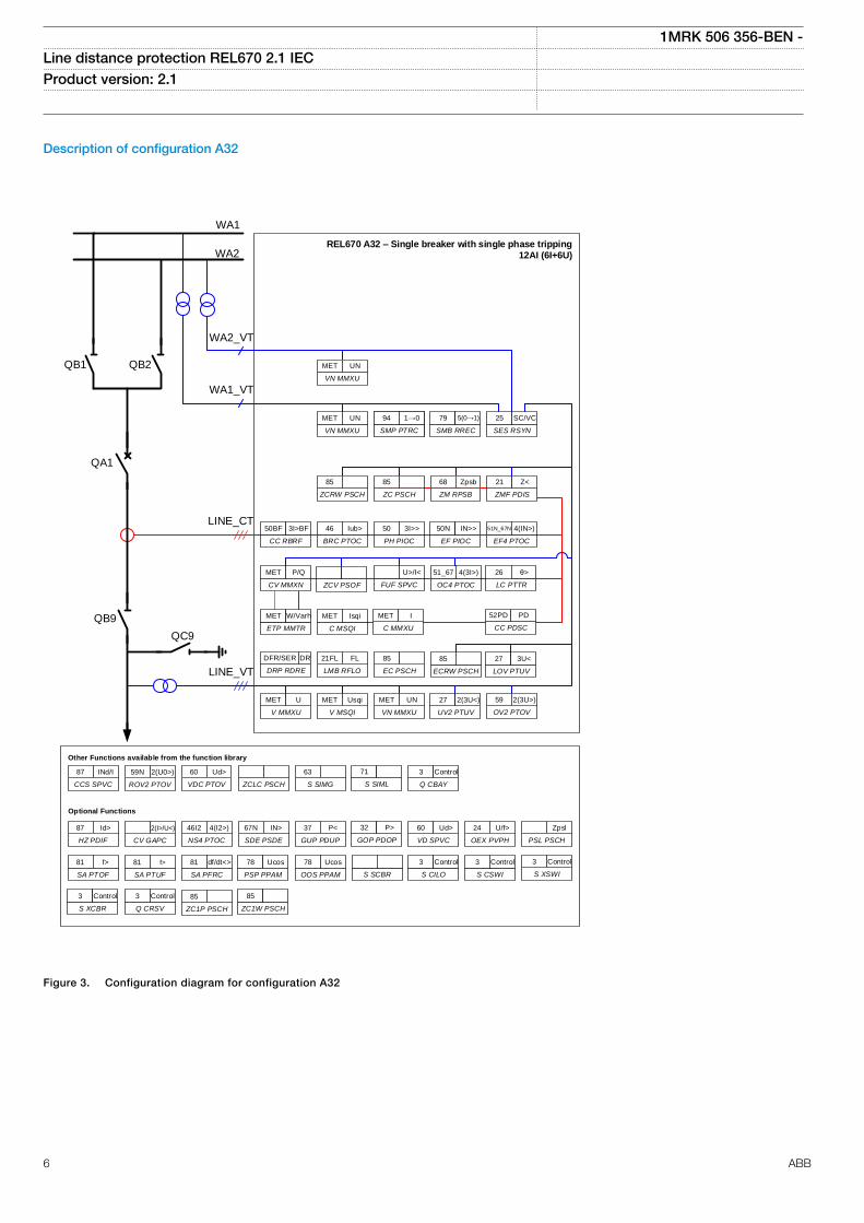
Description of configuration A32
QB1 QB2
QA1
QB9
QC9
WA1
WA2REL670 A32 – Single breaker with single phase tripping
12AI (6I+6U)
CC RBRF
50BF 3I>BF
26
LC PTTR
θ>
OC4 PTOC
51_67 4(3I>)
EF4 PTOC
51N_67N 4(IN>)
EF PIOC
50N IN>>
PH PIOC
50 3I>>
BRC PTOC
46 Iub>
Other Functions available from the function library
S CILO
3 Control
S CSWI
3 Control
ROV2 PTOV
59N 2(U0>)
CCS SPVC
87 INd/I
VDC PTOV
60 Ud>
NS4 PTOC
46I2 4(I2>)
HZ PDIF
87 Id>
CV GAPC
2(I>/U<)
VN MMXU
MET UN
VN MMXU
MET UN
Optional Functions
S SIMG
63
ZCLC PSCH S SIML
71
Q CBAY
3 Control
Q CRSV
3 Control
S XCBR
3 Control
S XSWI
3 Control
WA2_VT
WA1_VT
LINE_CT
LINE_VT
SMP PTRC
94 1->0
SMB RREC
79 5(0→1)
SMP PTRC
94 1→0
SES RSYN
25 SC/VC
UV2 PTUV
27 2(3U<)
V MSQI
MET Usqi
VN MMXU
MET UN
V MMXU
MET U
LMB RFLO
21FL FL
EC PSCH
85
ZCRW PSCH
85
ZC PSCH
85
ZM RPSB
68 Zpsb
ZMF PDIS
21 Z<
ZCV PSOF FUF SPVC
U>/I<
SDE PSDE
67N IN>
GUP PDUP
37 P<
PSL PSCH
Zpsl
VD SPVC
60 Ud>
OEX PVPH
24 U/f>
GOP PDOP
32 P>
SA PFRC
81 df/dt<>
SA PTOF
81 f>
SA PTUF
81 f>
PSP PPAM
78 Ucos
OOS PPAM
78 Ucos
S SCBR
DRP RDRE
DFR/SER DR
OV2 PTOV
59 2(3U>)
ECRW PSCH
85
LOV PTUV
27 3U<
C MMXU
MET I
C MSQI
MET Isqi
ETP MMTR
MET W/Varh
CV MMXN
MET P/Q
ZC1P PSCH
85
ZC1W PSCH
85
CC PDSC
52PD PD
IEC05000844 V4 EN
Figure 3. Configuration diagram for configuration A32
1MRK 506 356-BEN -Line distance protection REL670 2.1 IEC Product version: 2.1
6 ABB
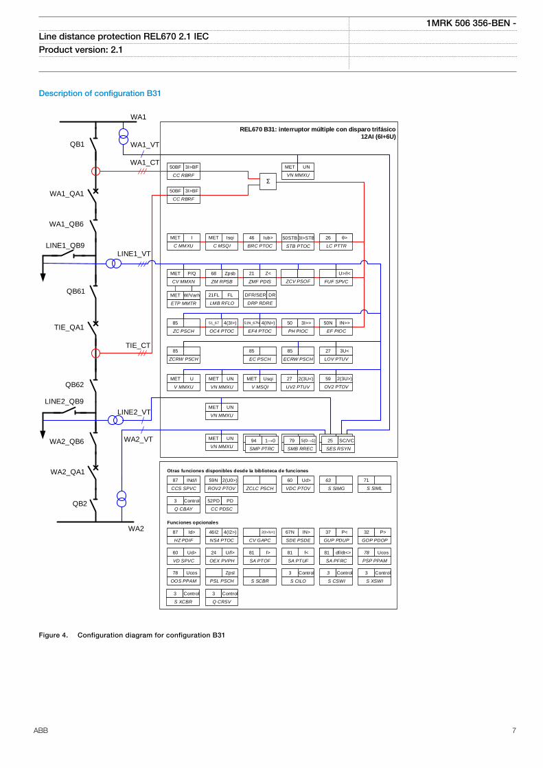
Description of configuration B31
QB1
WA1_QB6
LINE1_QB9
QB61
QB62
LINE2_QB9
WA2_QB6
WA1_QA1
TIE_QA1
REL670 B31: interruptor múltiple con disparo trifásico
12AI (6I+6U)
VN MMXU
MET UN
LMB RFLO
21FL FL
ETP MMTR
MET W/Varh
QB2
WA2_QA1
ZMF PDIS
21 Z<
V MSQI
MET Usqi
STB PTOC
50STB 3I>STB
C MSQI
MET Isqi
BRC PTOC
46 Iub>
LC PTTR
26 3I>STBθ>
EF PIOC
50N IN>>
Otras funciones disponibles desde la biblioteca de funciones
SA PTUF
81 f<
SA PFRC
81 f<
GUP PDUP
37 P<
NS4 PTOC
46I2 4(I2>)
CV GAPC
2(I>/U<)
VD SPVC
60 Ud>
SA PTOF
81 f>
Funciones opcionales
ROV2 PTOV
59N 2(U0>)
VDC PTOV
60 Ud>
PSP PPAM
78 Ucos
GOP PDOP
32 P>
ZM RPSB
68 Zpsb
UV2 PTUV
27 2(3U<)
V MMXU
MET U
CV MMXN
MET P/Q
CCS SPVC
87 INd/I
OEX PVPH
24 U/f>
ZCLC PSCH
SDE PSDE
67N IN>
HZ PDIF
87 Id>
SA PFRC
81 df/dt<>
OOS PPAM
78 Ucos
S SCBR
PSL PSCH
Zpsl
ZC PSCH
85
SMB RREC
79 0→1
SMP PTRC
94 1→0
SES RSYN
25 SC
SMB RREC
79 5(0→1)
SMP PTRC
94 1→0
SES RSYN
25 SC/VC
FUF SPVC
U>/I<
Σ
CC PDSC
52PD PD
S CILO
3 Control
S SIML
71
Q CBAY
3 Control
S CSWI
3 Control
Q CRSV
3 Control
S XSWI
3 Control
S XCBR
3 Control
S SIMG
63
CC RBRF
50BF 3I>BF
CC RBRF
50BF 3I>BF
ZCV PSOF
PH PIOC
50 3I>>
EF4 PTOC
51N_67N 4(IN>)
OC4 PTOC
51_67 4(3I>)
C MMXU
MET I
OV2 PTOV
59 2(3U>)
EC PSCH
85
LOV PTUV
27 3U<
ECRW PSCH
85
VN MMXU
MET UN
VN MMXU
MET UN
VN MMXU
MET UN
WA1
WA1_VT
WA1_CT
TIE_CT
LINE1_VT
WA2
WA2_VT
LINE2_VT
ZCRW PSCH
85
DRP RDRE
DFR/SER DR
IEC05000847 V4 EN
Figure 4. Configuration diagram for configuration B31
1MRK 506 356-BEN -Line distance protection REL670 2.1 IEC Product version: 2.1
ABB 7
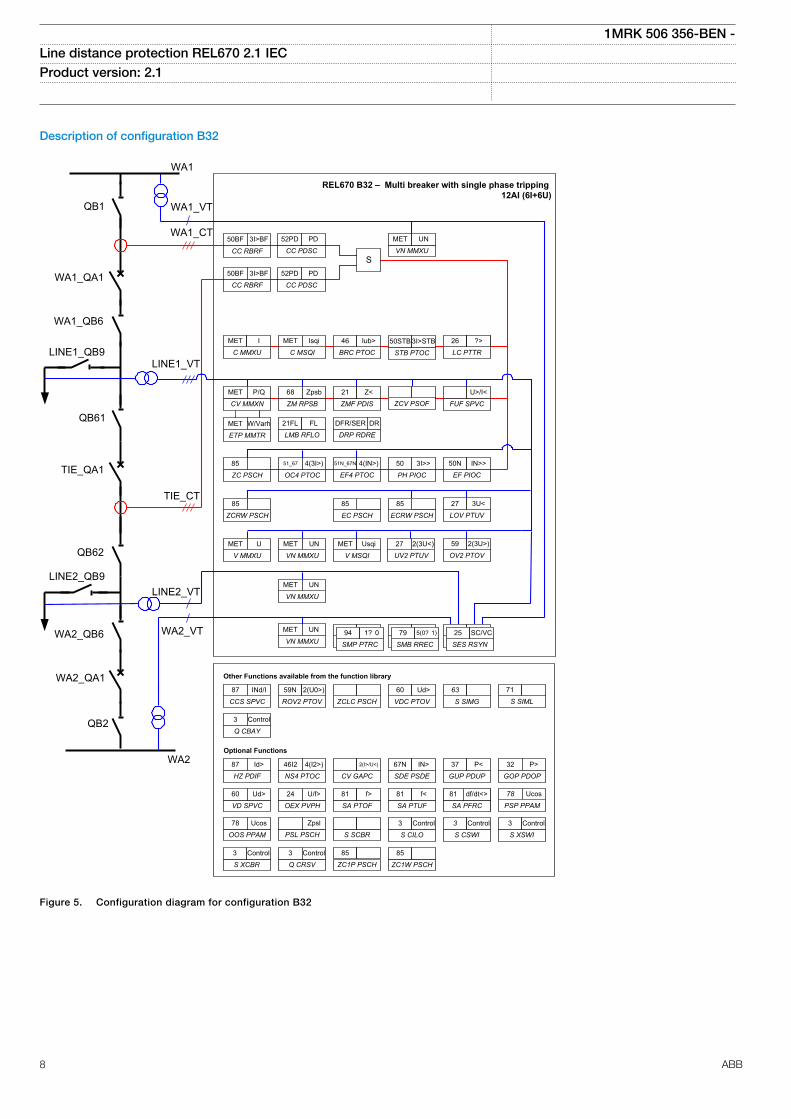
Description of configuration B32
QB1
WA1_QB6
LINE1_QB9
QB61
QB62
LINE2_QB9
WA2_QB6
WA1_QA1
TIE_QA1
REL670 B32 – Multi breaker with single phase tripping 12AI (6I+6U)
VN MMXU
MET UN
LMB RFLO
21FL FL
ETP MMTR
MET W/Varh
QB2
WA2_QA1
ZMF PDIS
21 Z<
V MSQI
MET Usqi
STB PTOC
50STB 3I>STBC MSQI
MET Isqi
BRC PTOC
46 Iub>
LC PTTR
26 3I>STB?>
EF PIOC
50N IN>>
Other Functions available from the function library
SA PTUF
81 f<
SA PFRC
81 f<
GUP PDUP
37 P<
NS4 PTOC
46I2 4(I2>)
CV GAPC
2(I>/U<)
VD SPVC
60 Ud>
SA PTOF
81 f>
Optional Functions
ROV2 PTOV
59N 2(U0>)
VDC PTOV
60 Ud>
PSP PPAM
78 Ucos
GOP PDOP
32 P>
ZM RPSB
68 Zpsb
UV2 PTUV
27 2(3U<)
V MMXU
MET U
CV MMXN
MET P/Q
CCS SPVC
87 INd/I
OEX PVPH
24 U/f>
ZCLC PSCH
SDE PSDE
67N IN>
HZ PDIF
87 Id>
SA PFRC
81 df/dt<>
OOS PPAM
78 Ucos
S SCBR
PSL PSCH
Zpsl
ZC PSCH
85
SMB RREC
79 0? 1
SMP PTRC
94 1? 0
SES RSYN
25 SC
SMB RREC
79 5(0? 1)
SMP PTRC
94 1? 0
SES RSYN
25 SC/VC
FUF SPVC
U>/I<
SCC PDSC
52PD PD
S CILO
3 Control
S SIML
71
Q CBAY
3 Control
S CSWI
3 Control
Q CRSV
3 Control
S XSWI
3 Control
S XCBR
3 Control
S SIMG
63
CC RBRF
50BF 3I>BF
CC RBRF
50BF 3I>BF
ZCV PSOF
PH PIOC
50 3I>>
EF4 PTOC
51N_67N 4(IN>)
OC4 PTOC
51_67 4(3I>)
C MMXU
MET I
OV2 PTOV
59 2(3U>)
EC PSCH
85
LOV PTUV
27 3U<
ECRW PSCH
85
VN MMXU
MET UN
VN MMXU
MET UN
VN MMXU
MET UN
WA1
WA1_VT
WA1_CT
TIE_CT
LINE1_VT
WA2
WA2_VT
LINE2_VT
ZCRW PSCH
85
DRP RDRE
DFR/SER DR
CC PDSC
52PD PD
ZC1P PSCH
85
ZC1W PSCH
85
IEC05000845 V4 EN
Figure 5. Configuration diagram for configuration B32
1MRK 506 356-BEN -Line distance protection REL670 2.1 IEC Product version: 2.1
8 ABB
Z <55
SC/VCO->I
3I>44
IN>44
I->O
CLOSE
TRIP
BUS A
BUS B
21
51/67
51N/67N
79 25
94/86
3I>50BF
TRIP BUSBAR
en05000276.vsd
3U>59
3U<27
2
22
2
IEC05000276-1 V1 EN
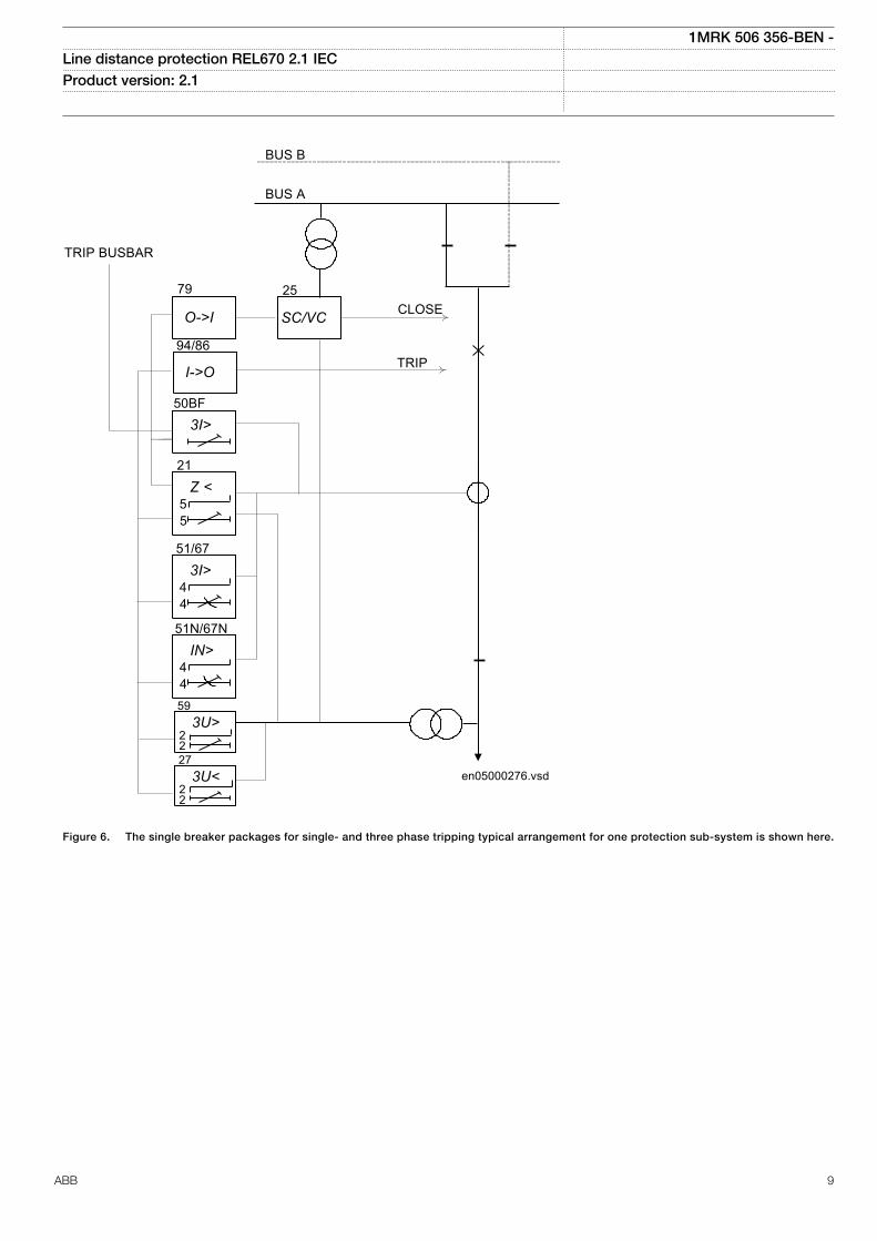
Figure 6. The single breaker packages for single- and three phase tripping typical arrangement for one protection sub-system is shown here.
1MRK 506 356-BEN -Line distance protection REL670 2.1 IEC Product version: 2.1
ABB 9
Z <55
SC/VCO->I
3I>44
IN>44
3U>22
3U<22
I->O
CLOSE
TRIP
BUS A
21
51/67
51N/67N
59
27
79 25
94/86
3I>50BF
TRIP BUSBAR & CB2
3I>50BF
S
SC/VCO->I
I->O CLO
SE
TRIP
25
94/86
79
IEC05000317-2-en.vsd
TRIP
CB1/3
CB1
CB2
IEC05000317 V2 EN
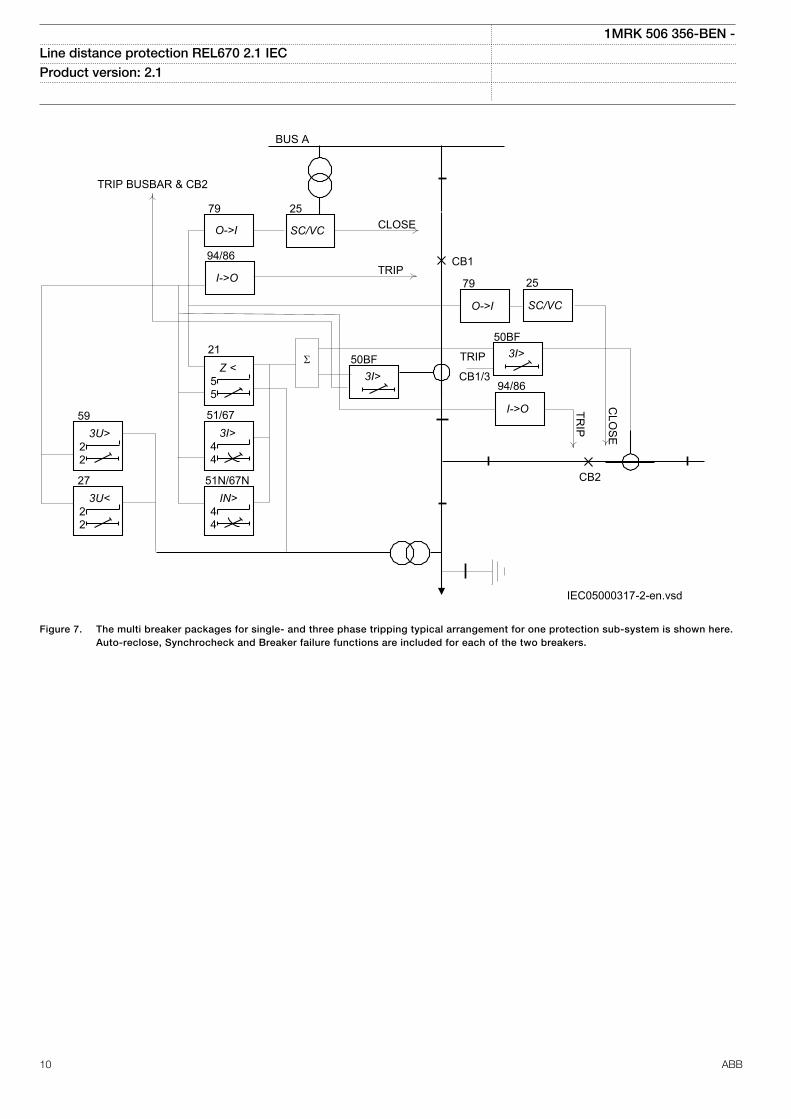
Figure 7. The multi breaker packages for single- and three phase tripping typical arrangement for one protection sub-system is shown here.Auto-reclose, Synchrocheck and Breaker failure functions are included for each of the two breakers.
1MRK 506 356-BEN -Line distance protection REL670 2.1 IEC Product version: 2.1
10 ABB

2. Available functions
Main protection functions
Table 1. Example of quantities
2 = number of basic instances0-3 = option quantities3-A03 = optional function included in packages A03 (refer to ordering details)
1MRK 506 356-BEN -Line distance protection REL670 2.1 IEC Product version: 2.1
ABB 11
IEC 61850 ANSI Function description Line Distance
REL670(Customized)
RE
L670
(A21
)
RE
L670
(A31
)
RE
L670
(B31
)
RE
L670
(A32
)
RE
L670
(B32
)
Differential protection
HZPDIF 87 1Ph high impedance differential protection 0-3 3-A02 3-A02 3-A02 3-A02
LDRGFC 11REL Additional security logic for differentialprotection
0-1
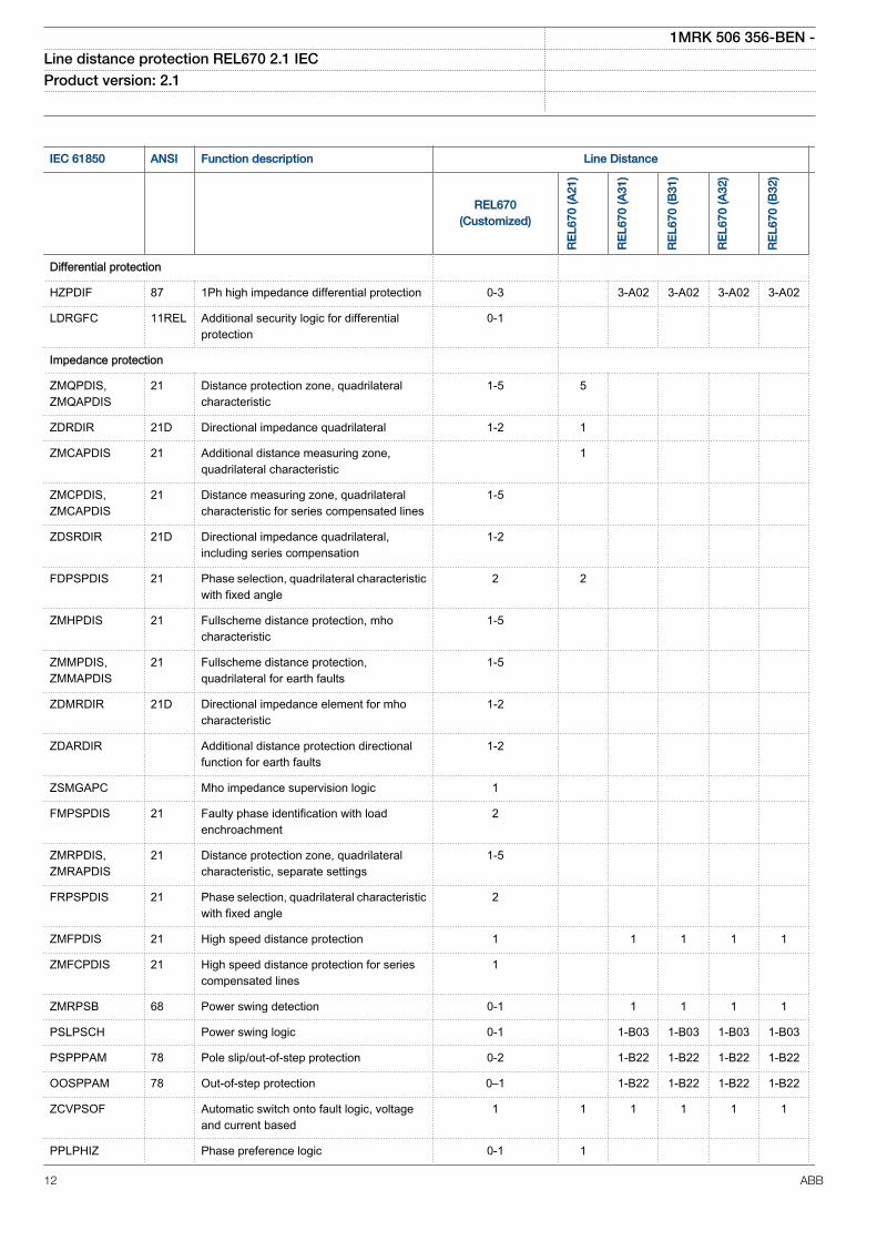
Impedance protection
ZMQPDIS,ZMQAPDIS
21 Distance protection zone, quadrilateralcharacteristic
1-5 5
ZDRDIR 21D Directional impedance quadrilateral 1-2 1
ZMCAPDIS 21 Additional distance measuring zone,quadrilateral characteristic
1
ZMCPDIS,ZMCAPDIS
21 Distance measuring zone, quadrilateralcharacteristic for series compensated lines
1-5
ZDSRDIR 21D Directional impedance quadrilateral,including series compensation
1-2
FDPSPDIS 21 Phase selection, quadrilateral characteristicwith fixed angle
2 2
ZMHPDIS 21 Fullscheme distance protection, mhocharacteristic
1-5
ZMMPDIS,ZMMAPDIS
21 Fullscheme distance protection,quadrilateral for earth faults
1-5
ZDMRDIR 21D Directional impedance element for mhocharacteristic
1-2
ZDARDIR Additional distance protection directionalfunction for earth faults
1-2
ZSMGAPC Mho impedance supervision logic 1
FMPSPDIS 21 Faulty phase identification with loadenchroachment
2
ZMRPDIS,ZMRAPDIS
21 Distance protection zone, quadrilateralcharacteristic, separate settings
1-5
FRPSPDIS 21 Phase selection, quadrilateral characteristicwith fixed angle
2
ZMFPDIS 21 High speed distance protection 1 1 1 1 1
ZMFCPDIS 21 High speed distance protection for seriescompensated lines
1
ZMRPSB 68 Power swing detection 0-1 1 1 1 1
PSLPSCH Power swing logic 0-1 1-B03 1-B03 1-B03 1-B03
PSPPPAM 78 Pole slip/out-of-step protection 0-2 1-B22 1-B22 1-B22 1-B22
OOSPPAM 78 Out-of-step protection 0–1 1-B22 1-B22 1-B22 1-B22
ZCVPSOF Automatic switch onto fault logic, voltageand current based
1 1 1 1 1 1
PPLPHIZ Phase preference logic 0-1 1
1MRK 506 356-BEN -Line distance protection REL670 2.1 IEC Product version: 2.1
12 ABB
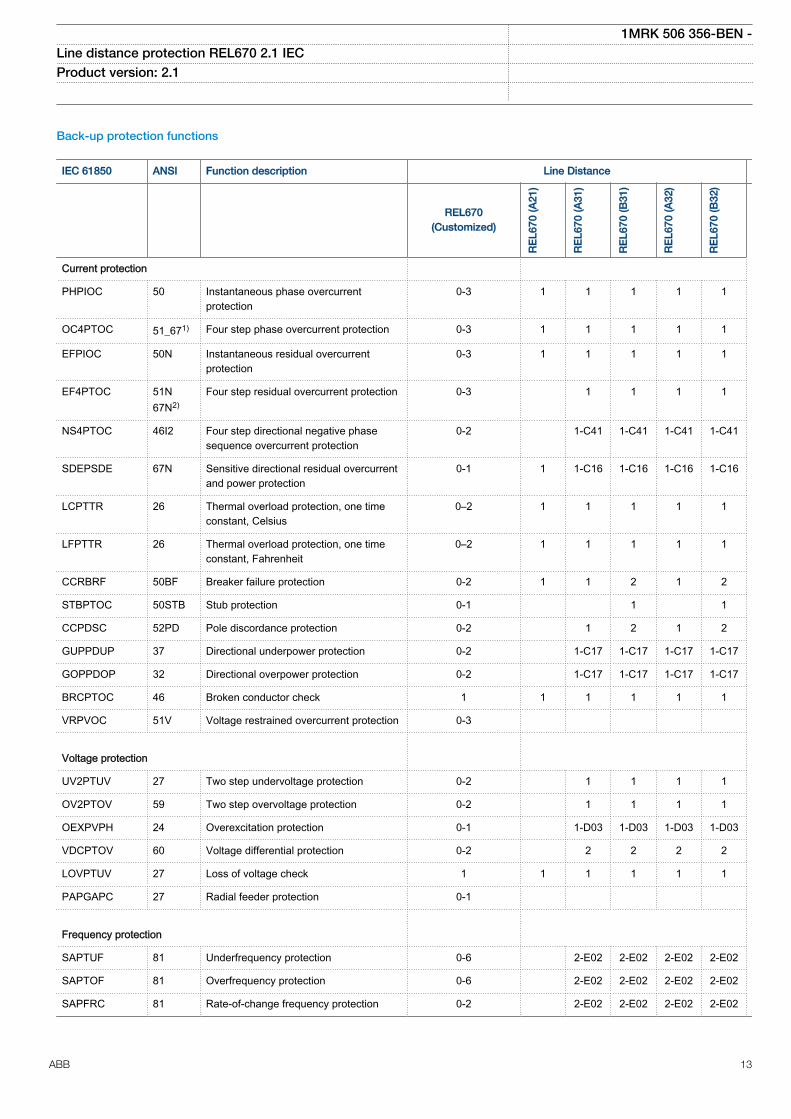
Back-up protection functions
IEC 61850 ANSI Function description Line Distance
REL670(Customized)
RE
L670
(A21
)
RE
L670
(A31
)
RE
L670
(B31
)
RE
L670
(A32
)
RE
L670
(B32
)
Current protection
PHPIOC 50 Instantaneous phase overcurrentprotection
0-3 1 1 1 1 1
OC4PTOC 51_671) Four step phase overcurrent protection 0-3 1 1 1 1 1
EFPIOC 50N Instantaneous residual overcurrentprotection
0-3 1 1 1 1 1
EF4PTOC 51N67N2)
Four step residual overcurrent protection 0-3 1 1 1 1
NS4PTOC 46I2 Four step directional negative phasesequence overcurrent protection
0-2 1-C41 1-C41 1-C41 1-C41
SDEPSDE 67N Sensitive directional residual overcurrentand power protection
0-1 1 1-C16 1-C16 1-C16 1-C16
LCPTTR 26 Thermal overload protection, one timeconstant, Celsius
0–2 1 1 1 1 1
LFPTTR 26 Thermal overload protection, one timeconstant, Fahrenheit
0–2 1 1 1 1 1
CCRBRF 50BF Breaker failure protection 0-2 1 1 2 1 2
STBPTOC 50STB Stub protection 0-1 1 1
CCPDSC 52PD Pole discordance protection 0-2 1 2 1 2
GUPPDUP 37 Directional underpower protection 0-2 1-C17 1-C17 1-C17 1-C17
GOPPDOP 32 Directional overpower protection 0-2 1-C17 1-C17 1-C17 1-C17
BRCPTOC 46 Broken conductor check 1 1 1 1 1 1
VRPVOC 51V Voltage restrained overcurrent protection 0-3
Voltage protection
UV2PTUV 27 Two step undervoltage protection 0-2 1 1 1 1
OV2PTOV 59 Two step overvoltage protection 0-2 1 1 1 1
OEXPVPH 24 Overexcitation protection 0-1 1-D03 1-D03 1-D03 1-D03
VDCPTOV 60 Voltage differential protection 0-2 2 2 2 2
LOVPTUV 27 Loss of voltage check 1 1 1 1 1 1
PAPGAPC 27 Radial feeder protection 0-1
Frequency protection
SAPTUF 81 Underfrequency protection 0-6 2-E02 2-E02 2-E02 2-E02
SAPTOF 81 Overfrequency protection 0-6 2-E02 2-E02 2-E02 2-E02
SAPFRC 81 Rate-of-change frequency protection 0-2 2-E02 2-E02 2-E02 2-E02
1MRK 506 356-BEN -Line distance protection REL670 2.1 IEC Product version: 2.1
ABB 13
IEC 61850 ANSI Function description Line Distance
REL670(Customized)
RE
L670
(A21
)
RE
L670
(A31
)
RE
L670
(B31
)
RE
L670
(A32
)
RE
L670
(B32
)
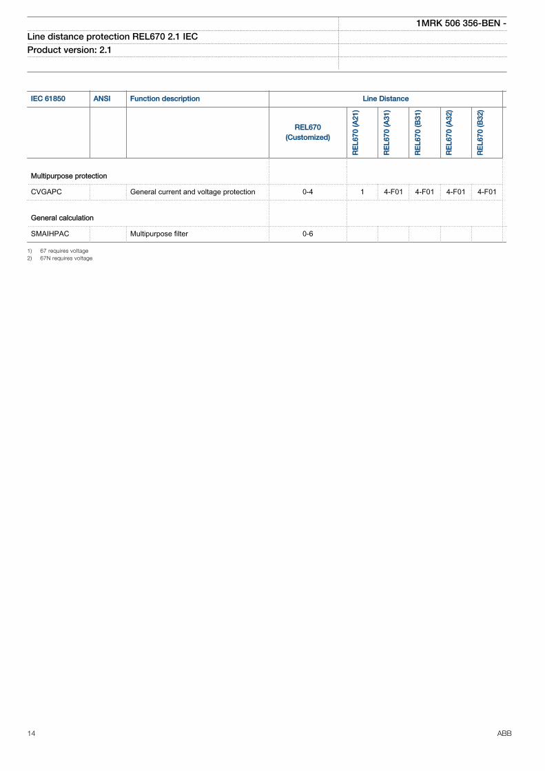
Multipurpose protection
CVGAPC General current and voltage protection 0-4 1 4-F01 4-F01 4-F01 4-F01
General calculation
SMAIHPAC Multipurpose filter 0-6
1) 67 requires voltage2) 67N requires voltage
1MRK 506 356-BEN -Line distance protection REL670 2.1 IEC Product version: 2.1
14 ABB
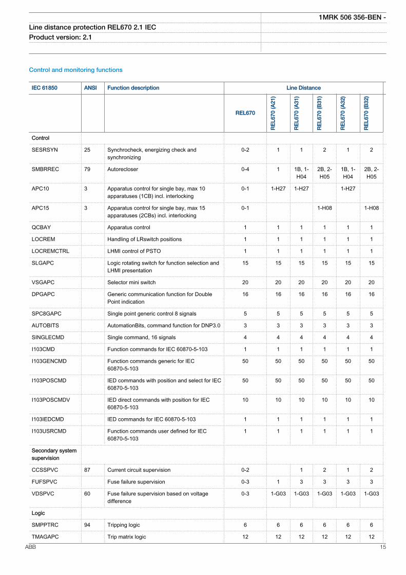
Control and monitoring functions
IEC 61850 ANSI Function description Line Distance
REL670
RE
L670
(A21
)
RE
L670
(A31
)
RE
L670
(B31
)
RE
L670
(A32
)
RE
L670
(B32
)
Control
SESRSYN 25 Synchrocheck, energizing check andsynchronizing
0-2 1 1 2 1 2
SMBRREC 79 Autorecloser 0-4 1 1B, 1-H04
2B, 2-H05
1B, 1-H04
2B, 2-H05
APC10 3 Apparatus control for single bay, max 10apparatuses (1CB) incl. interlocking
0-1 1-H27 1-H27 1-H27
APC15 3 Apparatus control for single bay, max 15apparatuses (2CBs) incl. interlocking
0-1 1-H08 1-H08
QCBAY Apparatus control 1 1 1 1 1 1
LOCREM Handling of LRswitch positions 1 1 1 1 1 1
LOCREMCTRL LHMI control of PSTO 1 1 1 1 1 1
SLGAPC Logic rotating switch for function selection andLHMI presentation
15 15 15 15 15 15
VSGAPC Selector mini switch 20 20 20 20 20 20
DPGAPC Generic communication function for DoublePoint indication
16 16 16 16 16 16
SPC8GAPC Single point generic control 8 signals 5 5 5 5 5 5
AUTOBITS AutomationBits, command function for DNP3.0 3 3 3 3 3 3
SINGLECMD Single command, 16 signals 4 4 4 4 4 4
I103CMD Function commands for IEC 60870-5-103 1 1 1 1 1 1
I103GENCMD Function commands generic for IEC60870-5-103
50 50 50 50 50 50
I103POSCMD IED commands with position and select for IEC60870-5-103
50 50 50 50 50 50
I103POSCMDV IED direct commands with position for IEC60870-5-103
10 10 10 10 10 10
I103IEDCMD IED commands for IEC 60870-5-103 1 1 1 1 1 1
I103USRCMD Function commands user defined for IEC60870-5-103
1 1 1 1 1 1
Secondary systemsupervision
CCSSPVC 87 Current circuit supervision 0-2 1 2 1 2
FUFSPVC Fuse failure supervision 0-3 1 3 3 3 3
VDSPVC 60 Fuse failure supervision based on voltagedifference
0-3 1-G03 1-G03 1-G03 1-G03 1-G03
Logic
SMPPTRC 94 Tripping logic 6 6 6 6 6 6
TMAGAPC Trip matrix logic 12 12 12 12 12 12
1MRK 506 356-BEN -Line distance protection REL670 2.1 IEC Product version: 2.1
ABB 15
IEC 61850 ANSI Function description Line Distance
REL670
RE
L670
(A21
)
RE
L670
(A31
)
RE
L670
(B31
)
RE
L670
(A32
)
RE
L670
(B32
)
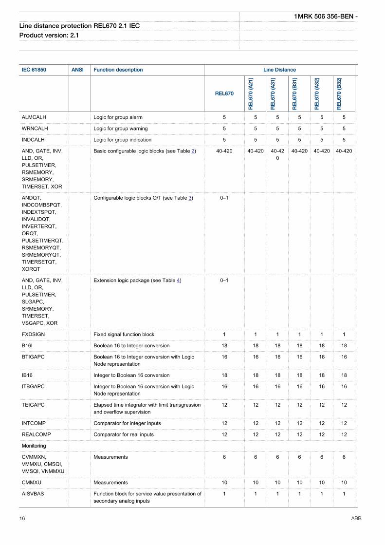
ALMCALH Logic for group alarm 5 5 5 5 5 5
WRNCALH Logic for group warning 5 5 5 5 5 5
INDCALH Logic for group indication 5 5 5 5 5 5
AND, GATE, INV,LLD, OR,PULSETIMER,RSMEMORY,SRMEMORY,TIMERSET, XOR
Basic configurable logic blocks (see Table 2) 40-420 40-420 40-420
40-420 40-420 40-420
ANDQT,INDCOMBSPQT,INDEXTSPQT,INVALIDQT,INVERTERQT,ORQT,PULSETIMERQT,RSMEMORYQT,SRMEMORYQT,TIMERSETQT,XORQT
Configurable logic blocks Q/T (see Table 3) 0–1
AND, GATE, INV,LLD, OR,PULSETIMER,SLGAPC,SRMEMORY,TIMERSET,VSGAPC, XOR
Extension logic package (see Table 4) 0–1
FXDSIGN Fixed signal function block 1 1 1 1 1 1
B16I Boolean 16 to Integer conversion 18 18 18 18 18 18
BTIGAPC Boolean 16 to Integer conversion with LogicNode representation
16 16 16 16 16 16
IB16 Integer to Boolean 16 conversion 18 18 18 18 18 18
ITBGAPC Integer to Boolean 16 conversion with LogicNode representation
16 16 16 16 16 16
TEIGAPC Elapsed time integrator with limit transgressionand overflow supervision
12 12 12 12 12 12
INTCOMP Comparator for integer inputs 12 12 12 12 12 12
REALCOMP Comparator for real inputs 12 12 12 12 12 12
Monitoring
CVMMXN,VMMXU, CMSQI,VMSQI, VNMMXU
Measurements 6 6 6 6 6 6
CMMXU Measurements 10 10 10 10 10 10
AISVBAS Function block for service value presentation ofsecondary analog inputs
1 1 1 1 1 1
1MRK 506 356-BEN -Line distance protection REL670 2.1 IEC Product version: 2.1
16 ABB
IEC 61850 ANSI Function description Line Distance
REL670
RE
L670
(A21
)
RE
L670
(A31
)
RE
L670
(B31
)
RE
L670
(A32
)
RE
L670
(B32
)
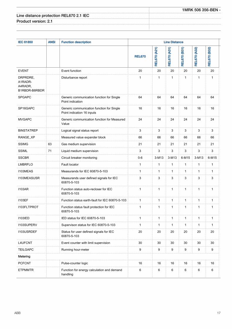
EVENT Event function 20 20 20 20 20 20
DRPRDRE,A1RADR-A4RADR,B1RBDR-B8RBDR
Disturbance report 1 1 1 1 1 1
SPGAPC Generic communication function for SinglePoint indication
64 64 64 64 64 64
SP16GAPC Generic communication function for SinglePoint indication 16 inputs
16 16 16 16 16 16
MVGAPC Generic communication function for MeasuredValue
24 24 24 24 24 24
BINSTATREP Logical signal status report 3 3 3 3 3 3
RANGE_XP Measured value expander block 66 66 66 66 66 66
SSIMG 63 Gas medium supervision 21 21 21 21 21 21
SSIML 71 Liquid medium supervision 3 3 3 3 3 3
SSCBR Circuit breaker monitoring 0-6 3-M13 3-M13 6-M15 3-M13 6-M15
LMBRFLO Fault locator 1 1 1 1 1 1
I103MEAS Measurands for IEC 60870-5-103 1 1 1 1 1 1
I103MEASUSR Measurands user defined signals for IEC60870-5-103
3 3 3 3 3 3
I103AR Function status auto-recloser for IEC60870-5-103
1 1 1 1 1 1
I103EF Function status earth-fault for IEC 60870-5-103 1 1 1 1 1 1
I103FLTPROT Function status fault protection for IEC60870-5-103
1 1 1 1 1 1
I103IED IED status for IEC 60870-5-103 1 1 1 1 1 1
I103SUPERV Supervison status for IEC 60870-5-103 1 1 1 1 1 1
I103USRDEF Status for user defined signals for IEC60870-5-103
20 20 20 20 20 20
L4UFCNT Event counter with limit supervision 30 30 30 30 30 30
TEILGAPC Running hour-meter 9 9 9 9 9 9
Metering
PCFCNT Pulse-counter logic 16 16 16 16 16 16
ETPMMTR Function for energy calculation and demandhandling
6 6 6 6 6 6
1MRK 506 356-BEN -Line distance protection REL670 2.1 IEC Product version: 2.1
ABB 17
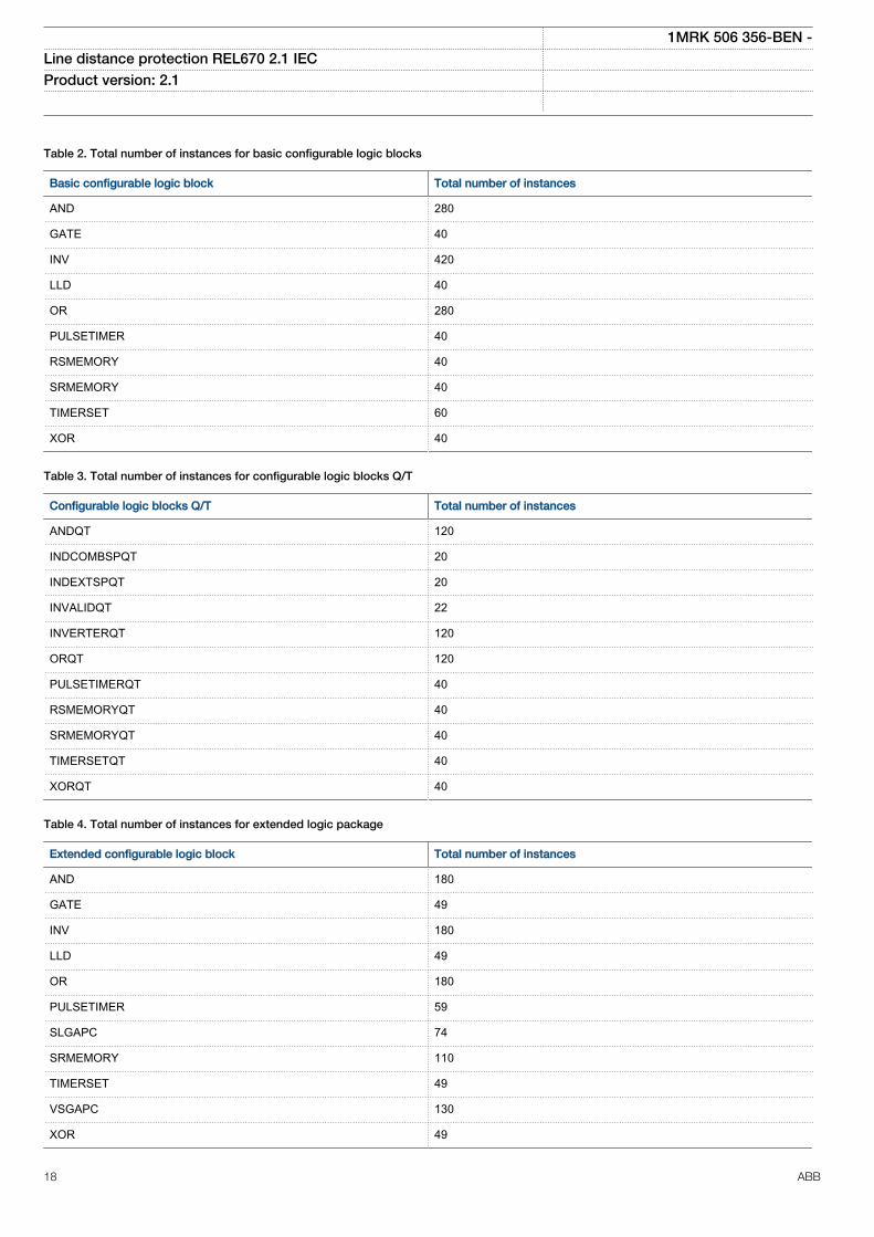
Table 2. Total number of instances for basic configurable logic blocks
Basic configurable logic block Total number of instances
AND 280
GATE 40
INV 420
LLD 40
OR 280
PULSETIMER 40
RSMEMORY 40
SRMEMORY 40
TIMERSET 60
XOR 40
Table 3. Total number of instances for configurable logic blocks Q/T
Configurable logic blocks Q/T Total number of instances
ANDQT 120
INDCOMBSPQT 20
INDEXTSPQT 20
INVALIDQT 22
INVERTERQT 120
ORQT 120
PULSETIMERQT 40
RSMEMORYQT 40
SRMEMORYQT 40
TIMERSETQT 40
XORQT 40
Table 4. Total number of instances for extended logic package
Extended configurable logic block Total number of instances
AND 180
GATE 49
INV 180
LLD 49
OR 180
PULSETIMER 59
SLGAPC 74
SRMEMORY 110
TIMERSET 49
VSGAPC 130
XOR 49
1MRK 506 356-BEN -Line distance protection REL670 2.1 IEC Product version: 2.1
18 ABB
Communication
IEC 61850 ANSI Function description Line Distance
REL670(Customized)
RE
L670
(A21
)
RE
L670
(A31
)
RE
L670
(B31
)
RE
L670
(A32
)
RE
L670
(B32
)
Station communication
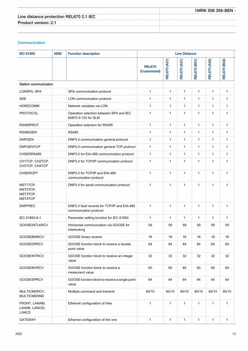
LONSPA, SPA SPA communication protocol 1 1 1 1 1 1
ADE LON communication protocol 1 1 1 1 1 1
HORZCOMM Network variables via LON 1 1 1 1 1 1
PROTOCOL Operation selection between SPA and IEC60870-5-103 for SLM
1 1 1 1 1 1
RS485PROT Operation selection for RS485 1 1 1 1 1 1
RS485GEN RS485 1 1 1 1 1 1
DNPGEN DNP3.0 communication general protocol 1 1 1 1 1 1
DNPGENTCP DNP3.0 communication general TCP protocol 1 1 1 1 1 1
CHSERRS485 DNP3.0 for EIA-485 communication protocol 1 1 1 1 1 1
CH1TCP, CH2TCP,CH3TCP, CH4TCP
DNP3.0 for TCP/IP communication protocol 1 1 1 1 1 1
CHSEROPT DNP3.0 for TCP/IP and EIA-485communication protocol
1 1 1 1 1 1
MST1TCP,MST2TCP,MST3TCP,MST4TCP
DNP3.0 for serial communication protocol 1 1 1 1 1 1
DNPFREC DNP3.0 fault records for TCP/IP and EIA-485communication protocol
1 1 1 1 1 1
IEC 61850-8-1 Parameter setting function for IEC 61850 1 1 1 1 1 1
GOOSEINTLKRCV Horizontal communication via GOOSE forinterlocking
59 59 59 59 59 59
GOOSEBINRCV GOOSE binary receive 16 16 16 16 16 16
GOOSEDPRCV GOOSE function block to receive a doublepoint value
64 64 64 64 64 64
GOOSEINTRCV GOOSE function block to receive an integervalue
32 32 32 32 32 32
GOOSEMVRCV GOOSE function block to receive ameasurand value
60 60 60 60 60 60
GOOSESPRCV GOOSE function block to receive a single pointvalue
64 64 64 64 64 64
MULTICMDRCV,MULTICMDSND
Multiple command and transmit 60/10 60/10 60/10 60/10 60/10 60/10
FRONT, LANABI,LANAB, LANCDI,LANCD
Ethernet configuration of links 1 1 1 1 1 1
GATEWAY Ethernet configuration of link one 1 1 1 1 1 1
1MRK 506 356-BEN -Line distance protection REL670 2.1 IEC Product version: 2.1
ABB 19
IEC 61850 ANSI Function description Line Distance
REL670(Customized)
RE
L670
(A21
)
RE
L670
(A31
)
RE
L670
(B31
)
RE
L670
(A32
)
RE
L670
(B32
)
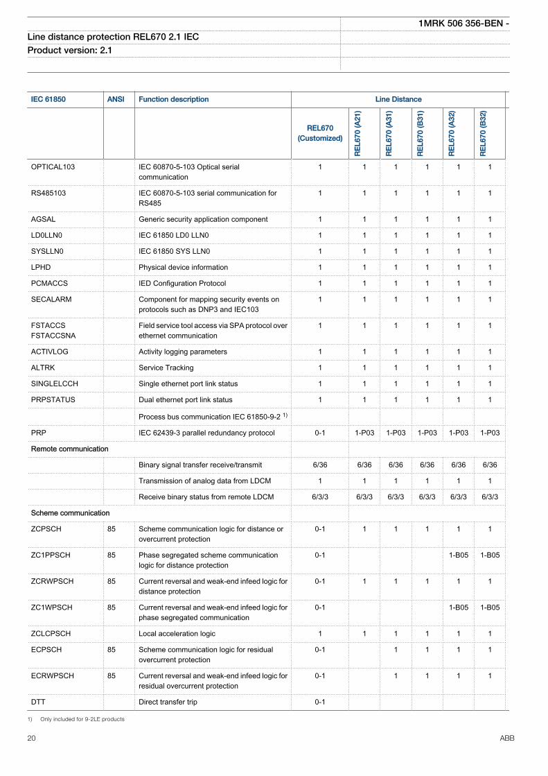
OPTICAL103 IEC 60870-5-103 Optical serialcommunication
1 1 1 1 1 1
RS485103 IEC 60870-5-103 serial communication forRS485
1 1 1 1 1 1
AGSAL Generic security application component 1 1 1 1 1 1
LD0LLN0 IEC 61850 LD0 LLN0 1 1 1 1 1 1
SYSLLN0 IEC 61850 SYS LLN0 1 1 1 1 1 1
LPHD Physical device information 1 1 1 1 1 1
PCMACCS IED Configuration Protocol 1 1 1 1 1 1
SECALARM Component for mapping security events onprotocols such as DNP3 and IEC103
1 1 1 1 1 1
FSTACCSFSTACCSNA
Field service tool access via SPA protocol overethernet communication
1 1 1 1 1 1
ACTIVLOG Activity logging parameters 1 1 1 1 1 1
ALTRK Service Tracking 1 1 1 1 1 1
SINGLELCCH Single ethernet port link status 1 1 1 1 1 1
PRPSTATUS Dual ethernet port link status 1 1 1 1 1 1
Process bus communication IEC 61850-9-2 1)
PRP IEC 62439-3 parallel redundancy protocol 0-1 1-P03 1-P03 1-P03 1-P03 1-P03
Remote communication
Binary signal transfer receive/transmit 6/36 6/36 6/36 6/36 6/36 6/36
Transmission of analog data from LDCM 1 1 1 1 1 1
Receive binary status from remote LDCM 6/3/3 6/3/3 6/3/3 6/3/3 6/3/3 6/3/3
Scheme communication
ZCPSCH 85 Scheme communication logic for distance orovercurrent protection
0-1 1 1 1 1 1
ZC1PPSCH 85 Phase segregated scheme communicationlogic for distance protection
0-1 1-B05 1-B05
ZCRWPSCH 85 Current reversal and weak-end infeed logic fordistance protection
0-1 1 1 1 1 1
ZC1WPSCH 85 Current reversal and weak-end infeed logic forphase segregated communication
0-1 1-B05 1-B05
ZCLCPSCH Local acceleration logic 1 1 1 1 1 1
ECPSCH 85 Scheme communication logic for residualovercurrent protection
0-1 1 1 1 1
ECRWPSCH 85 Current reversal and weak-end infeed logic forresidual overcurrent protection
0-1 1 1 1 1
DTT Direct transfer trip 0-1
1) Only included for 9-2LE products
1MRK 506 356-BEN -Line distance protection REL670 2.1 IEC Product version: 2.1
20 ABB
Basic IED functions
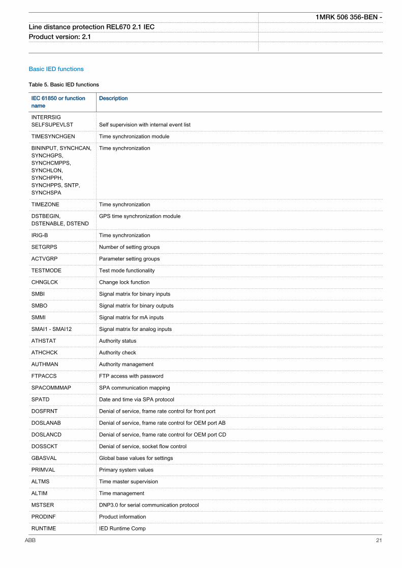
Table 5. Basic IED functions
IEC 61850 or functionname
Description
INTERRSIGSELFSUPEVLST Self supervision with internal event list
TIMESYNCHGEN Time synchronization module
BININPUT, SYNCHCAN,SYNCHGPS,SYNCHCMPPS,SYNCHLON,SYNCHPPH,SYNCHPPS, SNTP,SYNCHSPA
Time synchronization
TIMEZONE Time synchronization
DSTBEGIN,DSTENABLE, DSTEND
GPS time synchronization module
IRIG-B Time synchronization
SETGRPS Number of setting groups
ACTVGRP Parameter setting groups
TESTMODE Test mode functionality
CHNGLCK Change lock function
SMBI Signal matrix for binary inputs
SMBO Signal matrix for binary outputs
SMMI Signal matrix for mA inputs
SMAI1 - SMAI12 Signal matrix for analog inputs
ATHSTAT Authority status
ATHCHCK Authority check
AUTHMAN Authority management
FTPACCS FTP access with password
SPACOMMMAP SPA communication mapping
SPATD Date and time via SPA protocol
DOSFRNT Denial of service, frame rate control for front port
DOSLANAB Denial of service, frame rate control for OEM port AB
DOSLANCD Denial of service, frame rate control for OEM port CD
DOSSCKT Denial of service, socket flow control
GBASVAL Global base values for settings
PRIMVAL Primary system values
ALTMS Time master supervision
ALTIM Time management
MSTSER DNP3.0 for serial communication protocol
PRODINF Product information
RUNTIME IED Runtime Comp
1MRK 506 356-BEN -Line distance protection REL670 2.1 IEC Product version: 2.1
ABB 21
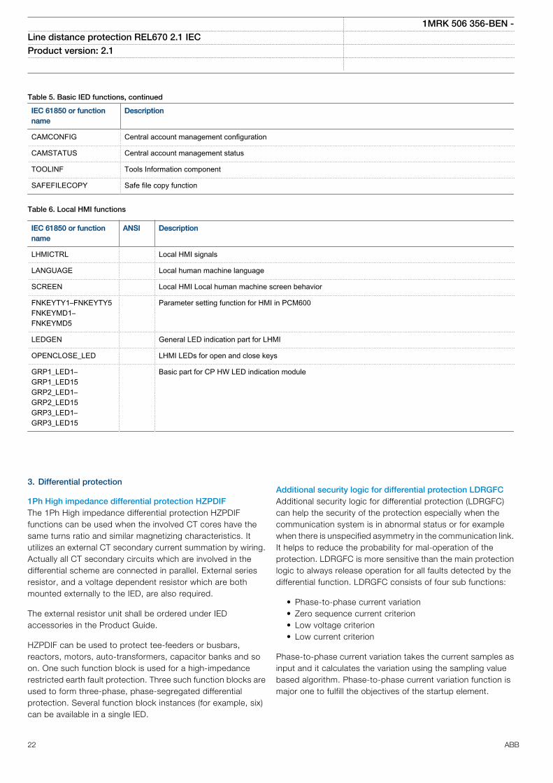
Table 5. Basic IED functions, continued
IEC 61850 or functionname
Description
CAMCONFIG Central account management configuration
CAMSTATUS Central account management status
TOOLINF Tools Information component
SAFEFILECOPY Safe file copy function
Table 6. Local HMI functions
IEC 61850 or functionname
ANSI Description
LHMICTRL Local HMI signals
LANGUAGE Local human machine language
SCREEN Local HMI Local human machine screen behavior
FNKEYTY1–FNKEYTY5FNKEYMD1–FNKEYMD5
Parameter setting function for HMI in PCM600
LEDGEN General LED indication part for LHMI
OPENCLOSE_LED LHMI LEDs for open and close keys
GRP1_LED1–GRP1_LED15GRP2_LED1–GRP2_LED15GRP3_LED1–GRP3_LED15
Basic part for CP HW LED indication module
3. Differential protection
1Ph High impedance differential protection HZPDIFThe 1Ph High impedance differential protection HZPDIFfunctions can be used when the involved CT cores have thesame turns ratio and similar magnetizing characteristics. Itutilizes an external CT secondary current summation by wiring.Actually all CT secondary circuits which are involved in thedifferential scheme are connected in parallel. External seriesresistor, and a voltage dependent resistor which are bothmounted externally to the IED, are also required.
The external resistor unit shall be ordered under IEDaccessories in the Product Guide.
HZPDIF can be used to protect tee-feeders or busbars,reactors, motors, auto-transformers, capacitor banks and soon. One such function block is used for a high-impedancerestricted earth fault protection. Three such function blocks areused to form three-phase, phase-segregated differentialprotection. Several function block instances (for example, six)can be available in a single IED.
Additional security logic for differential protection LDRGFCAdditional security logic for differential protection (LDRGFC)can help the security of the protection especially when thecommunication system is in abnormal status or for examplewhen there is unspecified asymmetry in the communication link.It helps to reduce the probability for mal-operation of theprotection. LDRGFC is more sensitive than the main protectionlogic to always release operation for all faults detected by thedifferential function. LDRGFC consists of four sub functions:
• Phase-to-phase current variation• Zero sequence current criterion• Low voltage criterion• Low current criterion
Phase-to-phase current variation takes the current samples asinput and it calculates the variation using the sampling valuebased algorithm. Phase-to-phase current variation function ismajor one to fulfill the objectives of the startup element.
1MRK 506 356-BEN -Line distance protection REL670 2.1 IEC Product version: 2.1
22 ABB
Zero sequence criterion takes the zero sequence current asinput. It increases the security of protection during the highimpedance fault conditions.
Low voltage criterion takes the phase voltages and phase-to-phase voltages as inputs. It increases the security of protectionwhen the three-phase fault occurred on the weak end side.
Low current criterion takes the phase currents as inputs and itincreases the dependability during the switch onto fault case ofunloaded line.
The differential function can be allowed to trip as no load is fedthrough the line and protection is not working correctly.
Features:
• Startup element is sensitive enough to detect theabnormal status of the protected system
• Startup element does not influence the operation speed ofmain protection
• Startup element would detect the evolving faults, highimpedance faults and three phase fault on weak side
• It is possible to block the each sub function of startupelement
• Startup signal has a settable pulse time
4. Impedance protection
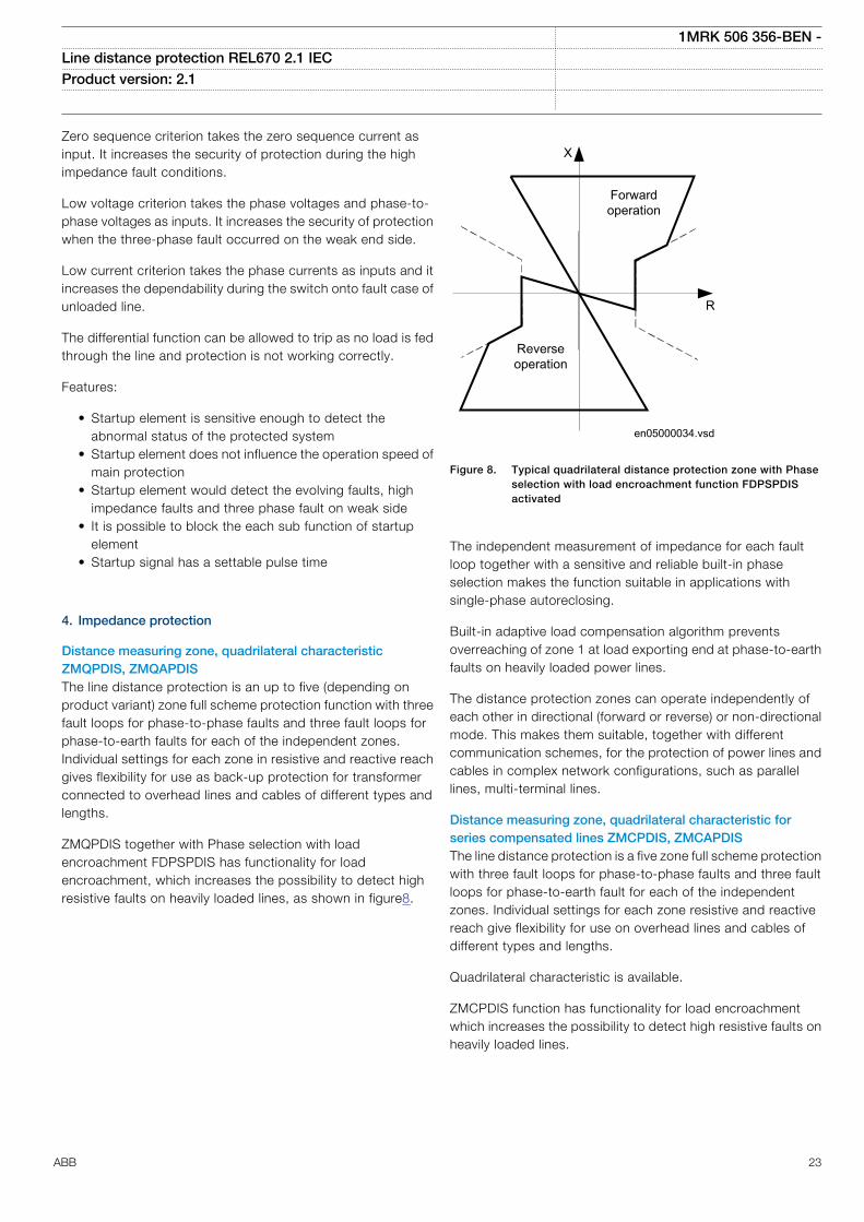
Distance measuring zone, quadrilateral characteristicZMQPDIS, ZMQAPDISThe line distance protection is an up to five (depending onproduct variant) zone full scheme protection function with threefault loops for phase-to-phase faults and three fault loops forphase-to-earth faults for each of the independent zones.Individual settings for each zone in resistive and reactive reachgives flexibility for use as back-up protection for transformerconnected to overhead lines and cables of different types andlengths.
ZMQPDIS together with Phase selection with loadencroachment FDPSPDIS has functionality for loadencroachment, which increases the possibility to detect highresistive faults on heavily loaded lines, as shown in figure8.
en05000034.vsd
R
X
Forwardoperation
Reverseoperation
IEC05000034 V1 EN
Figure 8. Typical quadrilateral distance protection zone with Phaseselection with load encroachment function FDPSPDISactivated
The independent measurement of impedance for each faultloop together with a sensitive and reliable built-in phaseselection makes the function suitable in applications withsingle-phase autoreclosing.
Built-in adaptive load compensation algorithm preventsoverreaching of zone 1 at load exporting end at phase-to-earthfaults on heavily loaded power lines.
The distance protection zones can operate independently ofeach other in directional (forward or reverse) or non-directionalmode. This makes them suitable, together with differentcommunication schemes, for the protection of power lines andcables in complex network configurations, such as parallellines, multi-terminal lines.
Distance measuring zone, quadrilateral characteristic forseries compensated lines ZMCPDIS, ZMCAPDISThe line distance protection is a five zone full scheme protectionwith three fault loops for phase-to-phase faults and three faultloops for phase-to-earth fault for each of the independentzones. Individual settings for each zone resistive and reactivereach give flexibility for use on overhead lines and cables ofdifferent types and lengths.
Quadrilateral characteristic is available.
ZMCPDIS function has functionality for load encroachmentwhich increases the possibility to detect high resistive faults onheavily loaded lines.
1MRK 506 356-BEN -Line distance protection REL670 2.1 IEC Product version: 2.1
ABB 23
en05000034.vsd
R
X
Forwardoperation
Reverseoperation
IEC05000034 V1 EN
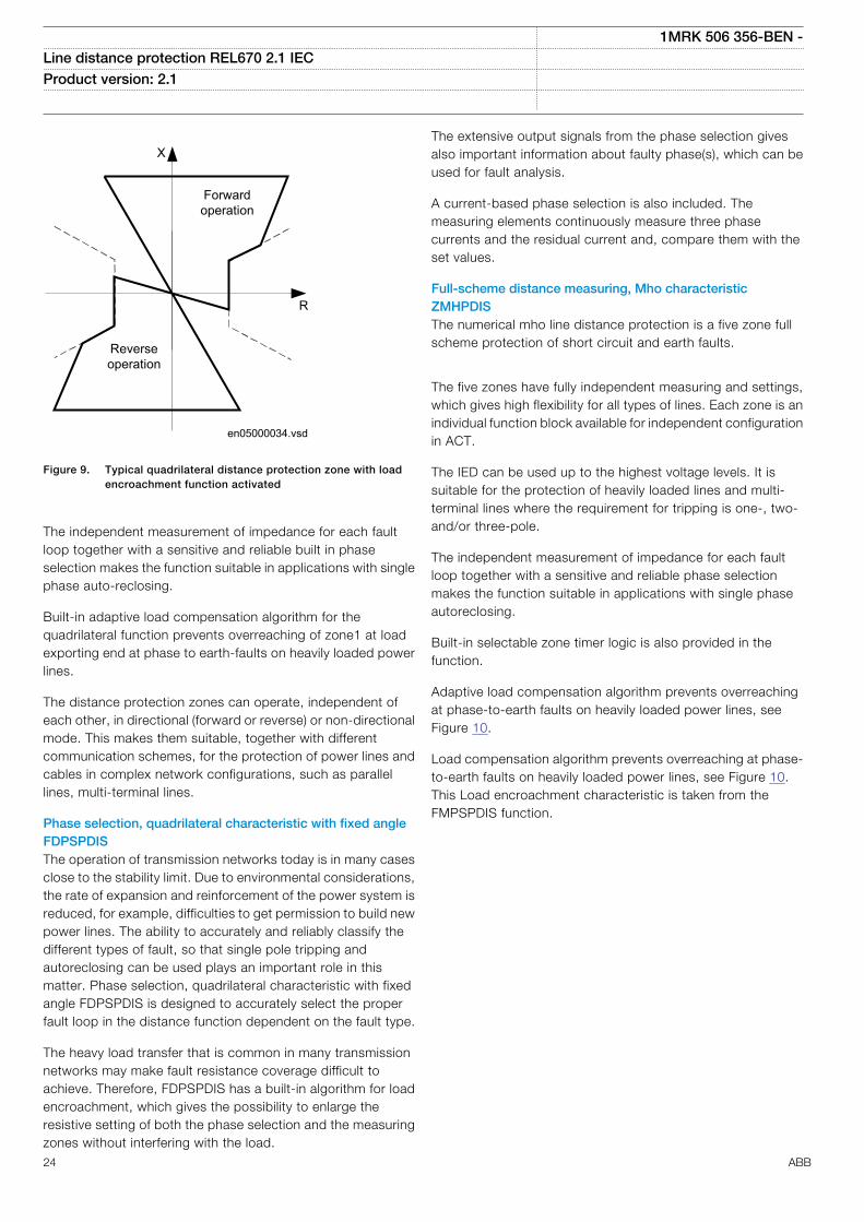
Figure 9. Typical quadrilateral distance protection zone with loadencroachment function activated
The independent measurement of impedance for each faultloop together with a sensitive and reliable built in phaseselection makes the function suitable in applications with singlephase auto-reclosing.
Built-in adaptive load compensation algorithm for thequadrilateral function prevents overreaching of zone1 at loadexporting end at phase to earth-faults on heavily loaded powerlines.
The distance protection zones can operate, independent ofeach other, in directional (forward or reverse) or non-directionalmode. This makes them suitable, together with differentcommunication schemes, for the protection of power lines andcables in complex network configurations, such as parallellines, multi-terminal lines.
Phase selection, quadrilateral characteristic with fixed angleFDPSPDISThe operation of transmission networks today is in many casesclose to the stability limit. Due to environmental considerations,the rate of expansion and reinforcement of the power system isreduced, for example, difficulties to get permission to build newpower lines. The ability to accurately and reliably classify thedifferent types of fault, so that single pole tripping andautoreclosing can be used plays an important role in thismatter. Phase selection, quadrilateral characteristic with fixedangle FDPSPDIS is designed to accurately select the properfault loop in the distance function dependent on the fault type.
The heavy load transfer that is common in many transmissionnetworks may make fault resistance coverage difficult toachieve. Therefore, FDPSPDIS has a built-in algorithm for loadencroachment, which gives the possibility to enlarge theresistive setting of both the phase selection and the measuringzones without interfering with the load.
The extensive output signals from the phase selection givesalso important information about faulty phase(s), which can beused for fault analysis.
A current-based phase selection is also included. Themeasuring elements continuously measure three phasecurrents and the residual current and, compare them with theset values.
Full-scheme distance measuring, Mho characteristicZMHPDISThe numerical mho line distance protection is a five zone fullscheme protection of short circuit and earth faults.
The five zones have fully independent measuring and settings,which gives high flexibility for all types of lines. Each zone is anindividual function block available for independent configurationin ACT.
The IED can be used up to the highest voltage levels. It issuitable for the protection of heavily loaded lines and multi-terminal lines where the requirement for tripping is one-, two-and/or three-pole.
The independent measurement of impedance for each faultloop together with a sensitive and reliable phase selectionmakes the function suitable in applications with single phaseautoreclosing.
Built-in selectable zone timer logic is also provided in thefunction.
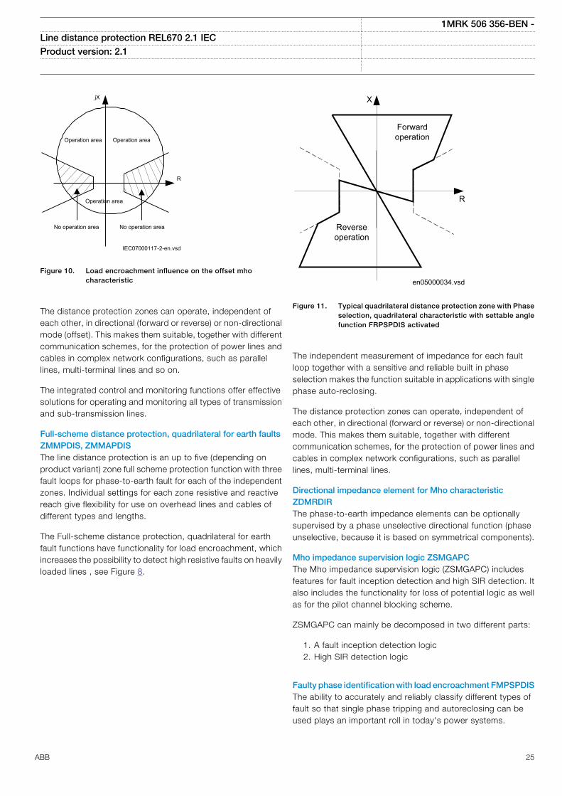
Adaptive load compensation algorithm prevents overreachingat phase-to-earth faults on heavily loaded power lines, seeFigure 10.
Load compensation algorithm prevents overreaching at phase-to-earth faults on heavily loaded power lines, see Figure 10.This Load encroachment characteristic is taken from theFMPSPDIS function.
1MRK 506 356-BEN -Line distance protection REL670 2.1 IEC Product version: 2.1
24 ABB
IEC07000117-2-en.vsd
jX
Operation area Operation area
R
Operation area
No operation area No operation area
IEC07000117 V2 EN
Figure 10. Load encroachment influence on the offset mhocharacteristic
The distance protection zones can operate, independent ofeach other, in directional (forward or reverse) or non-directionalmode (offset). This makes them suitable, together with differentcommunication schemes, for the protection of power lines andcables in complex network configurations, such as parallellines, multi-terminal lines and so on.
The integrated control and monitoring functions offer effectivesolutions for operating and monitoring all types of transmissionand sub-transmission lines.
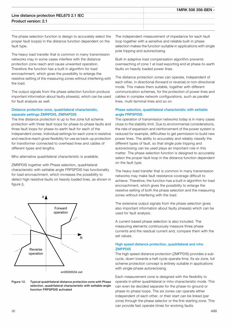
Full-scheme distance protection, quadrilateral for earth faultsZMMPDIS, ZMMAPDISThe line distance protection is an up to five (depending onproduct variant) zone full scheme protection function with threefault loops for phase-to-earth fault for each of the independentzones. Individual settings for each zone resistive and reactivereach give flexibility for use on overhead lines and cables ofdifferent types and lengths.
The Full-scheme distance protection, quadrilateral for earthfault functions have functionality for load encroachment, whichincreases the possibility to detect high resistive faults on heavilyloaded lines , see Figure 8.
en05000034.vsd
R
X
Forwardoperation
Reverseoperation
IEC05000034 V1 EN
Figure 11. Typical quadrilateral distance protection zone with Phaseselection, quadrilateral characteristic with settable anglefunction FRPSPDIS activated
The independent measurement of impedance for each faultloop together with a sensitive and reliable built in phaseselection makes the function suitable in applications with singlephase auto-reclosing.
The distance protection zones can operate, independent ofeach other, in directional (forward or reverse) or non-directionalmode. This makes them suitable, together with differentcommunication schemes, for the protection of power lines andcables in complex network configurations, such as parallellines, multi-terminal lines.
Directional impedance element for Mho characteristicZDMRDIRThe phase-to-earth impedance elements can be optionallysupervised by a phase unselective directional function (phaseunselective, because it is based on symmetrical components).
Mho impedance supervision logic ZSMGAPCThe Mho impedance supervision logic (ZSMGAPC) includesfeatures for fault inception detection and high SIR detection. Italso includes the functionality for loss of potential logic as wellas for the pilot channel blocking scheme.
ZSMGAPC can mainly be decomposed in two different parts:
1. A fault inception detection logic2. High SIR detection logic
Faulty phase identification with load encroachment FMPSPDISThe ability to accurately and reliably classify different types offault so that single phase tripping and autoreclosing can beused plays an important roll in today's power systems.
1MRK 506 356-BEN -Line distance protection REL670 2.1 IEC Product version: 2.1
ABB 25
The phase selection function is design to accurately select theproper fault loop(s) in the distance function dependent on thefault type.
The heavy load transfer that is common in many transmissionnetworks may in some cases interfere with the distanceprotection zone reach and cause unwanted operation.Therefore the function has a built in algorithm for loadencroachment, which gives the possibility to enlarge theresistive setting of the measuring zones without interfering withthe load.
The output signals from the phase selection function produceimportant information about faulty phase(s), which can be usedfor fault analysis as well.
Distance protection zone, quadrilateral characteristic,separate settings ZMRPDIS, ZMRAPDISThe line distance protection is up to five zone full schemeprotection with three fault loops for phase-to-phase faults andthree fault loops for phase-to-earth fault for each of theindependent zones. Individual settings for each zone in resistiveand reactive reach gives flexibility for use as back-up protectionfor transformer connected to overhead lines and cables ofdifferent types and lengths.
Mho alternative quadrilateral characteristic is available.
ZMRPDIS together with Phase selection, quadrilateralcharacteristic with settable angle FRPSPDIS has functionalityfor load encroachment, which increases the possibility todetect high resistive faults on heavily loaded lines, as shown infigure 8.
en05000034.vsd
R
X
Forwardoperation
Reverseoperation
IEC05000034 V1 EN
Figure 12. Typical quadrilateral distance protection zone with Phaseselection, quadrilateral characteristic with settable anglefunction FRPSPDIS activated
The independent measurement of impedance for each faultloop together with a sensitive and reliable built-in phaseselection makes the function suitable in applications with singlepole tripping and autoreclosing.
Built-in adaptive load compensation algorithm preventsoverreaching of zone 1 at load exporting end at phase-to-earthfaults on heavily loaded power lines.
The distance protection zones can operate, independent ofeach other, in directional (forward or reverse) or non-directionalmode. This makes them suitable, together with differentcommunication schemes, for the protection of power lines andcables in complex network configurations, such as parallellines, multi-terminal lines and so on.
Phase selection, quadrilateral characteristic with settableangle FRPSPDISThe operation of transmission networks today is in many casesclose to the stability limit. Due to environmental considerations,the rate of expansion and reinforcement of the power system isreduced for example, difficulties to get permission to build newpower lines. The ability to accurately and reliably classify thedifferent types of fault, so that single pole tripping andautoreclosing can be used plays an important role in thismatter. The phase selection function is designed to accuratelyselect the proper fault loop in the distance function dependenton the fault type.
The heavy load transfer that is common in many transmissionnetworks may make fault resistance coverage difficult toachieve. Therefore, the function has a built in algorithm for loadencroachment, which gives the possibility to enlarge theresistive setting of both the phase selection and the measuringzones without interfering with the load.
The extensive output signals from the phase selection givesalso important information about faulty phase(s) which can beused for fault analysis.
A current-based phase selection is also included. Themeasuring elements continuously measure three phasecurrents and the residual current and, compare them with theset values.
High speed distance protection, quadrilateral and mhoZMFPDISThe high speed distance protection (ZMFPDIS) provides a sub-cycle, down towards a half-cycle operate time. Its six zone, fullscheme protection concept is entirely suitable in applicationswith single-phase autoreclosing.
Each measurement zone is designed with the flexibility tooperate in either quadrilateral or mho characteristic mode. Thiscan even be decided separate for the phase-to-ground orphase-to-phase loops. The six zones can operate eitherindependent of each other, or their start can be linked (perzone) through the phase selector or the first starting zone. Thiscan provide fast operate times for evolving faults.
1MRK 506 356-BEN -Line distance protection REL670 2.1 IEC Product version: 2.1
26 ABB
The operation of the phase-selection is primarily based on acurrent change criteria (i.e. delta quantities), however there isalso a phase selection criterion operating in parallel whichbases its operation on voltage and current phasors exclusively.Additionally the directional element provides a fast and correctdirectional decision under difficult operating conditions,including close-in three-phase faults, simultaneous faults andfaults with only zero-sequence in-feed.During phase-to-earthfaults on heavily loaded power lines there is an adaptive loadcompensation algorithm that prevents overreaching of thedistance zones in the load exporting end, improving theselectivity of the function. This also reduces underreach in theimporting end.
Distance zones quad with high speed distance for seriescompensated networks ZMFCPDISThe high speed distance protection (ZMCPDIS) provides a sub-cycle, down towards a half-cycle operate time. Its six zone, fullscheme protection concept is entirely suitable in applicationswith single-phase autoreclosing.
High speed distance protection ZMFCPDIS is fundamentallythe same function as ZMFPDIS but provides more flexibility inzone settings to suit more complex applications, such as seriescompensated lines. In operation for series compensatednetworks, the parameters of the directional function are alteredto handle voltage reversal.
Each measurement zone is designed with the flexibility tooperate in either quadrilateral or mho characteristic mode. Thiscan even be decided separate for the phase-to-ground orphase-to-phase loops. The six zones can operate eitherindependent of each other, or their start can be linked (perzone) through the phase selector or the first starting zone. Thiscan provide fast operate times for evolving faults.
The operation of the phase-selection is primarily based on acurrent change criteria (i.e. delta quantities), however there isalso a phase selection criterion operating in parallel whichbases its operation on voltage and current phasors exclusively.Additionally the directional element provides a fast and correctdirectional decision under difficult operating conditions,including close-in three-phase faults, simultaneous faults andfaults with only zero-sequence in-feed.
During phase-to-earth faults on heavily loaded power linesthere is an adaptive load compensation algorithm that preventsoverreaching of the distance zones in the load exporting end,improving the selectivity of the function. This also reducesunderreach in the importing end.
Power swing detection ZMRPSBPower swings may occur after disconnection of heavy loads ortrip of big generation plants.
Power swing detection function ZMRPSB is used to detectpower swings and initiate block of all distance protection zones.
Occurrence of earth-fault currents during a power swinginhibits the ZMRPSB function, to allow fault clearance.
Power swing logic PSLPSCHPower Swing Logic (PSLPSCH) is a complementary function toPower Swing Detection (ZMRPSB) function. It providespossibility for selective tripping of faults on power lines duringsystem oscillations (power swings or pole slips), when thedistance protection function should normally be blocked. Thecomplete logic consists of two different parts:
• Communication and tripping part: provides selectivetripping on the basis of special distance protection zonesand a scheme communication logic, which are notblocked during the system oscillations.
• Blocking part: blocks unwanted operation ofinstantaneous distance protection zone 1 for oscillations,which are initiated by faults and their clearing on theadjacent power lines and other primary elements.
Pole slip protection PSPPPAMThe situation with pole slip of a generator can be caused bydifferent reasons.
A short circuit may occur in the external power grid, close to thegenerator. If the fault clearing time is too long, the generator willaccelerate so much, that the synchronism cannot bemaintained.
Undamped oscillations occur in the power system, wheregenerator groups at different locations, oscillate against eachother. If the connection between the generators is too weak themagnitude of the oscillations will increase until the angularstability is lost.
The operation of a generator having pole slip will give risk ofdamages to the generator, shaft and turbine.
• At each pole slip there will be significant torque impact onthe generator-turbine shaft.
• In asynchronous operation there will be induction ofcurrents in parts of the generator normally not carryingcurrent, thus resulting in increased heating. Theconsequence can be damages on insulation and stator/rotor iron.
The Pole slip protection (PSPPPAM) function shall detect poleslip conditions and trip the generator as fast as possible if thelocus of the measured impedance is inside the generator-transformer block. If the centre of pole slip is outside in thepower grid, the first action should be to split the network intotwo parts, after line protection action. If this fails there should beoperation of the generator PSPPPAM in zone 2, to preventfurther damages to the generator, shaft and turbine.
Pole slip protection PSPPPAMSudden events in an electric power system such as largechanges in load, fault occurrence or fault clearance, can cause
1MRK 506 356-BEN -Line distance protection REL670 2.1 IEC Product version: 2.1
ABB 27
power oscillations referred to as power swings. In a non-recoverable situation, the power swings become so severe thatthe synchronism is lost, a condition referred to as pole slipping.The main purpose of the pole slip protection (PSPPPAM) is todetect, evaluate, and take the required action for pole slippingoccurrences in the power system.
Out-of-step protection OOSPPAMThe out-of-step protection OOSPPAM function in the IED canbe used for both generator protection and as well for lineprotection applications.
The main purpose of the OOSPPAM function is to detect,evaluate, and take the required action during pole slippingoccurrences in the power system.
The OOSPPAM function detects pole slip conditions and tripsthe generator as fast as possible, after the first pole-slip if thecenter of oscillation is found to be in zone 1, which normallyincludes the generator and its step-up power transformer. If thecenter of oscillation is found to be further out in the powersystem, in zone 2, more than one pole-slip is usually allowedbefore the generator-transformer unit is disconnected. Aparameter setting is available to take into account the circuitbreaker opening time. If there are several out-of-step relays inthe power system, then the one which finds the center ofoscillation in its zone 1 should operate first.
Two current channels I3P1 and I3P2 are available in OOSPPAMfunction to allow the direct connection of two groups of three-phase currents; that may be needed for very powerfulgenerators, with stator windings split into two groups perphase, when each group is equipped with current transformers.The protection function performs a simple summation of thecurrents of the two channels I3P1 and I3P2.
Phase preference logic PPLPHIZThe optional phase preference logic main purpose is to providea selective tripping for cross-country faults in isolated or highimpedance-earthed networks.
Automatic switch onto fault logic, voltage and current basedZCVPSOFAutomatic switch onto fault logic (ZCVPSOF) is a function thatgives an instantaneous trip at closing of breaker onto a fault. Adead line detection check is provided to activate the functionwhen the line is dead.
5. Current protection
Instantaneous phase overcurrent protection PHPIOCThe instantaneous three phase overcurrent function has a lowtransient overreach and short tripping time to allow use as ahigh set short-circuit protection function.
Four-step phase overcurrent protection OC4PTOCThe four step three-phase overcurrent protection functionOC4PTOC has an inverse or definite time delay independent forstep 1 to 4 separately.
All IEC and ANSI inverse time characteristics are availabletogether with an optional user defined time characteristic.
The directional function needs voltage as it is voltage polarizedwith memory. The function can be set to be directional or non-directional independently for each of the steps.
A second harmonic blocking level can be set for the functionand can be used to block each step individually.
Instantaneous residual overcurrent protection EFPIOCThe Instantaneous residual overcurrent protection EFPIOC hasa low transient overreach and short tripping times to allow theuse for instantaneous earth-fault protection, with the reachlimited to less than the typical eighty percent of the line atminimum source impedance. EFPIOC is configured to measurethe residual current from the three-phase current inputs andcan be configured to measure the current from a separatecurrent input.
Four step residual overcurrent protection, zero sequence andnegative sequence direction EF4PTOCThe four step residual overcurrent protection EF4PTOC has aninverse or definite time delay independent for each step.
All IEC and ANSI time-delayed characteristics are availabletogether with an optional user defined characteristic.
EF4PTOC can be set directional or non-directionalindependently for each of the steps.
IDir, UPol and IPol can be independently selected to be eitherzero sequence or negative sequence.
Second harmonic blocking can be set individually for each step.
EF4PTOC can be used as main protection for phase-to-earthfaults.
EF4PTOC can also be used to provide a system back-up forexample, in the case of the primary protection being out ofservice due to communication or voltage transformer circuitfailure.
Directional operation can be combined together withcorresponding communication logic in permissive or blockingteleprotection scheme. Current reversal and weak-end infeedfunctionality are available as well.
Residual current can be calculated by summing the three phasecurrents or taking the input from neutral CT
1MRK 506 356-BEN -Line distance protection REL670 2.1 IEC Product version: 2.1
28 ABB
Four step negative sequence overcurrent protectionNS4PTOCFour step negative sequence overcurrent protection(NS4PTOC) has an inverse or definite time delay independentfor each step separately.
All IEC and ANSI time delayed characteristics are availabletogether with an optional user defined characteristic.
The directional function is voltage polarized.
NS4PTOC can be set directional or non-directionalindependently for each of the steps.
NS4PTOC can be used as main protection for unsymmetricalfault; phase-phase short circuits, phase-phase-earth shortcircuits and single phase earth faults.
NS4PTOC can also be used to provide a system backup forexample, in the case of the primary protection being out ofservice due to communication or voltage transformer circuitfailure.
Directional operation can be combined together withcorresponding communication logic in permissive or blockingteleprotection scheme. The same logic as for directional zerosequence current can be used. Current reversal and weak-endinfeed functionality are available.
Sensitive directional residual overcurrent and powerprotection SDEPSDEIn isolated networks or in networks with high impedanceearthing, the earth fault current is significantly smaller than theshort circuit currents. In addition to this, the magnitude of thefault current is almost independent on the fault location in thenetwork. The protection can be selected to use either theresidual current or residual power component 3U0·3I0·cos j,for operating quantity with maintained short circuit capacity.There is also available one nondirectional 3I0 step and one 3U0overvoltage tripping step.
No specific sensitive current input is needed. SDEPSDE can beset as low 0.25% of IBase.
Thermal overload protection, one time constant LCPTTR/LFPTTRThe increasing utilization of the power system closer to thethermal limits has generated a need of a thermal overloadprotection for power lines.
A thermal overload will often not be detected by otherprotection functions and the introduction of the thermaloverload protection can allow the protected circuit to operatecloser to the thermal limits.
The three-phase current measuring protection has an I2tcharacteristic with settable time constant and a thermalmemory. The temperature is displayed in either Celsius or
Fahrenheit, depending on whether the function used is LCPTTR(Celsius) or LFPTTR (Fahrenheit).
An alarm level gives early warning to allow operators to takeaction well before the line is tripped.
Estimated time to trip before operation, and estimated time toreclose after operation are presented.
Breaker failure protection CCRBRFBreaker failure protection (CCRBRF) ensures a fast backuptripping of the surrounding breakers in case the own breakerfails to open. CCRBRF can be current-based, contact-based oran adaptive combination of these two conditions.
A current check with extremely short reset time is used ascheck criterion to achieve high security against inadvertentoperation.
Contact check criteria can be used where the fault currentthrough the breaker is small.
CCRBRF can be single- or three-phase initiated to allow usewith single phase tripping applications. For the three-phaseversion of CCRBRF the current criteria can be set to operateonly if two out of four for example, two phases or one phaseplus the residual current start. This gives a higher security to theback-up trip command.
CCRBRF function can be programmed to give a single- orthree-phase re-trip of its own breaker to avoid unnecessarytripping of surrounding breakers at an incorrect initiation due tomistakes during testing.
Stub protection STBPTOCWhen a power line is taken out of service for maintenance andthe line disconnector is opened in multi-breaker arrangementsthe voltage transformers will mostly be outside on thedisconnected part. The primary line distance protection willthus not be able to operate and must be blocked.
The stub protection STBPTOC covers the zone between thecurrent transformers and the open disconnector. The three-phase instantaneous overcurrent function is released from anormally open, NO (b) auxiliary contact on the linedisconnector.
Pole discordance protection CCPDSCAn open phase can cause negative and zero sequence currentswhich cause thermal stress on rotating machines and cancause unwanted operation of zero sequence or negativesequence current functions.
Normally the own breaker is tripped to correct such a situation.If the situation persists the surrounding breakers should betripped to clear the unsymmetrical load situation.
The Pole discordance protection function CCPDSC operatesbased on information from auxiliary contacts of the circuit
1MRK 506 356-BEN -Line distance protection REL670 2.1 IEC Product version: 2.1
ABB 29
breaker for the three phases with additional criteria fromunsymmetrical phase currents when required.
Directional over/underpower protection GOPPDOP/GUPPDUPThe directional over-/under-power protection GOPPDOP/GUPPDUP can be used wherever a high/low active, reactive orapparent power protection or alarming is required. Thefunctions can alternatively be used to check the direction ofactive or reactive power flow in the power system. There are anumber of applications where such functionality is needed.Some of them are:
• detection of reversed active power flow• detection of high reactive power flow
Each function has two steps with definite time delay.
Broken conductor check BRCPTOCThe main purpose of the function Broken conductor check(BRCPTOC) is the detection of broken conductors on protectedpower lines and cables (series faults). Detection can be used togive alarm only or trip the line breaker.
Voltage-restrained time overcurrent protection VRPVOCVoltage-restrained time overcurrent protection (VRPVOC)function can be used as generator backup protection againstshort-circuits.
The overcurrent protection feature has a settable current levelthat can be used either with definite time or inverse timecharacteristic. Additionally, it can be voltage controlled/restrained.
One undervoltage step with definite time characteristic is alsoavailable within the function in order to provide functionality forovercurrent protection with undervoltage seal-in.
6. Voltage protection
Two step undervoltage protection UV2PTUVUndervoltages can occur in the power system during faults orabnormal conditions. Two step undervoltage protection(UV2PTUV) function can be used to open circuit breakers toprepare for system restoration at power outages or as long-time delayed back-up to primary protection.
UV2PTUV has two voltage steps, each with inverse or definitetime delay.
UV2PTUV has a high reset ratio to allow settings close tosystem service voltage.
Two step overvoltage protection OV2PTOVOvervoltages may occur in the power system during abnormalconditions such as sudden power loss, tap changer regulatingfailures, and open line ends on long lines.
Two step overvoltage protection (OV2PTOV) function can beused to detect open line ends, normally then combined with adirectional reactive over-power function to supervise thesystem voltage. When triggered, the function will cause analarm, switch in reactors, or switch out capacitor banks.
OV2PTOV has two voltage steps, each of them with inverse ordefinite time delayed.
OV2PTOV has a high reset ratio to allow settings close tosystem service voltage.
Overexcitation protection OEXPVPHWhen the laminated core of a power transformer or generator issubjected to a magnetic flux density beyond its design limits,stray flux will flow into non-laminated components that are notdesigned to carry flux. This will cause eddy currents to flow.These eddy currents can cause excessive heating and severedamage to insulation and adjacent parts in a relatively shorttime. The function has settable inverse operating curves andindependent alarm stages.
Voltage differential protection VDCPTOVA voltage differential monitoring function is available. Itcompares the voltages from two three phase sets of voltagetransformers and has one sensitive alarm step and one tripstep.
Loss of voltage check LOVPTUVLoss of voltage check LOVPTUV is suitable for use in networkswith an automatic system restoration function. LOVPTUVissues a three-pole trip command to the circuit breaker, if allthree phase voltages fall below the set value for a time longerthan the set time and the circuit breaker remains closed.
The operation of LOVPTUV is supervised by the fuse failuresupervision FUFSPVC.
Radial feeder protection PAPGAPCThe PAPGAPC function is used to provide protection of radialfeeders having passive loads or weak end in-feed sources. It ispossible to achieve fast tripping using communication systemwith remote end or delayed tripping not requiringcommunication or upon communication system failure. For fasttripping, scheme communication is required. Delayed trippingdoes not require scheme communication.
The PAPGAPC function performs phase selection usingmeasured voltages. Each phase voltage is compared to theopposite phase-phase voltage. A phase is deemed to have afault if its phase voltage drops below a settable percentage ofthe opposite phase-phase voltage. The phase - phase voltagesinclude memory. This memory function has a settable timeconstant.
The voltage-based phase selection is used for both fast anddelayed tripping. To achieve fast tripping, schemecommunication is required. Delayed tripping does not requirescheme communication. It is possible to permit delayed
1MRK 506 356-BEN -Line distance protection REL670 2.1 IEC Product version: 2.1
30 ABB
tripping only upon failure of the communications channel byblocking the delayed tripping logic with a communicationschannel healthy input signal.
On receipt of the communications signal, phase selectiveoutputs for fast tripping are set based on the phase(s) in whichthe phase selection function has operated.
For delayed tripping, single pole and three pole delays areseparately and independently settable. Furthermore, it ispossible to enable or disable single pole and three pole delayedtripping. For single phase faults, it is possible to include aresidual current check in the tripping logic. Three pole trippingis always selected for phase selection on more than one phase.Three pole tripping will also occur if the residual currentexceeds the set level during fuse failure for a time longer thanthe three pole trip delay time.
7. Frequency protection
Underfrequency protection SAPTUFUnderfrequency occurs as a result of a lack of generation in thenetwork.
Underfrequency protection SAPTUF measures frequency withhigh accuracy, and is used for load shedding systems, remedialaction schemes, gas turbine startup and so on. Separatedefinite time delays are provided for operate and restore.
SAPTUF is provided with undervoltage blocking.
The operation is based on positive sequence voltagemeasurement and requires two phase-phase or three phase-neutral voltages to be connected. For information about how toconnect analog inputs, refer to Application manual/IEDapplication/Analog inputs/Setting guidelines
Overfrequency protection SAPTOFOverfrequency protection function SAPTOF is applicable in allsituations, where reliable detection of high fundamental powersystem frequency is needed.
Overfrequency occurs because of sudden load drops or shuntfaults in the power network. Close to the generating plant,generator governor problems can also cause over frequency.
SAPTOF measures frequency with high accuracy, and is usedmainly for generation shedding and remedial action schemes. Itis also used as a frequency stage initiating load restoring. Adefinite time delay is provided for operate.
SAPTOF is provided with an undervoltage blocking.
The operation is based on positive sequence voltagemeasurement and requires two phase-phase or three phase-neutral voltages to be connected. For information about how toconnect analog inputs, refer to Application manual/IEDapplication/Analog inputs/Setting guidelines
Rate-of-change frequency protection SAPFRCThe rate-of-change frequency protection function SAPFRCgives an early indication of a main disturbance in the system.SAPFRC measures frequency with high accuracy, and can beused for generation shedding, load shedding and remedialaction schemes. SAPFRC can discriminate between a positiveor negative change of frequency. A definite time delay isprovided for operate.
SAPFRC is provided with an undervoltage blocking. Theoperation is based on positive sequence voltage measurementand requires two phase-phase or three phase-neutral voltagesto be connected. For information about how to connect analoginputs, refer to Application manual/IED application/Analoginputs/Setting guidelines.
8. Multipurpose protection
General current and voltage protection CVGAPCThe General current and voltage protection (CVGAPC) can beutilized as a negative sequence current protection detectingunsymmetrical conditions such as open phase orunsymmetrical faults.
CVGAPC can also be used to improve phase selection for highresistive earth faults, outside the distance protection reach, forthe transmission line. Three functions are used, whichmeasures the neutral current and each of the three phasevoltages. This will give an independence from load currents andthis phase selection will be used in conjunction with thedetection of the earth fault from the directional earth faultprotection function.
Voltage-restrained time overcurrent protection VRPVOCVoltage-restrained time overcurrent protection (VRPVOC)function can be used as generator backup protection againstshort-circuits.
The overcurrent protection feature has a settable current levelthat can be used either with definite time or inverse timecharacteristic. Additionally, it can be voltage controlled/restrained.
One undervoltage step with definite time characteristic is alsoavailable within the function in order to provide functionality forovercurrent protection with undervoltage seal-in.
9. Secondary system supervision
Current circuit supervision CCSSPVCOpen or short circuited current transformer cores can causeunwanted operation of many protection functions such asdifferential, earth-fault current and negative-sequence currentfunctions.
Current circuit supervision (CCSSPVC) compares the residualcurrent from a three phase set of current transformer cores with
1MRK 506 356-BEN -Line distance protection REL670 2.1 IEC Product version: 2.1
ABB 31
the neutral point current on a separate input taken from anotherset of cores on the current transformer.
A detection of a difference indicates a fault in the circuit and isused as alarm or to block protection functions expected to giveinadvertent tripping.
Fuse failure supervision FUFSPVCThe aim of the fuse failure supervision function FUFSPVC is toblock voltage measuring functions at failures in the secondarycircuits between the voltage transformer and the IED in order toavoid inadvertent operations that otherwise might occur.
The fuse failure supervision function basically has three differentdetection methods, negative sequence and zero sequencebased detection and an additional delta voltage and deltacurrent detection.
The negative sequence detection algorithm is recommendedfor IEDs used in isolated or high-impedance earthed networks.It is based on the negative-sequence quantities.
The zero sequence detection is recommended for IEDs used indirectly or low impedance earthed networks. It is based on thezero sequence measuring quantities.
The selection of different operation modes is possible by asetting parameter in order to take into account the particularearthing of the network.
A criterion based on delta current and delta voltagemeasurements can be added to the fuse failure supervisionfunction in order to detect a three phase fuse failure, which inpractice is more associated with voltage transformer switchingduring station operations.
Fuse failure supervision VDSPVCDifferent protection functions within the protection IEDoperates on the basis of measured voltage at the relay point.Some example of protection functions are:
• Distance protection function.• Undervoltage function.• Energisation function and voltage check for the weak
infeed logic.
These functions can operate unintentionally, if a fault occurs inthe secondary circuits between voltage instrumenttransformers and the IED. These unintentional operations canbe prevented by VDSPVC.
VDSPVC is designed to detect fuse failures or faults in voltagemeasurement circuit, based on phase wise comparison ofvoltages of main and pilot fused circuits. VDSPVC blockingoutput can be configured to block functions that need to beblocked in case of faults in the voltage circuit.
Multipurpose filter SMAIHPACThe multi-purpose filter function block, SMAIHPAC, is arrangedas a three-phase filter. It has very much the same user interface
(e.g. inputs and outputs) as the standard pre-processingfunction block SMAI. However the main difference is that it canbe used to extract any frequency component from the inputsignal. Thus it can, for example, be used to build sub-synchronous resonance protection for synchronous generator.
10. Control
Synchrocheck, energizing check, and synchronizing SESRSYNThe Synchronizing function allows closing of asynchronousnetworks at the correct moment including the breaker closingtime, which improves the network stability.
Synchrocheck, energizing check, and synchronizing SESRSYNfunction checks that the voltages on both sides of the circuitbreaker are in synchronism, or with at least one side dead toensure that closing can be done safely.
SESRSYN function includes a built-in voltage selection schemefor double bus and 1½ breaker or ring busbar arrangements.
Manual closing as well as automatic reclosing can be checkedby the function and can have different settings.
For systems, which are running asynchronous, a synchronizingfunction is provided. The main purpose of the synchronizingfunction is to provide controlled closing of circuit breakers whentwo asynchronous systems are going to be connected. Thesynchronizing function evaluates voltage difference, phaseangle difference, slip frequency and frequency rate of changebefore issuing a controlled closing of the circuit breaker.Breaker closing time is a parameter setting.
Autorecloser SMBRRECThe autorecloser SMBRREC function provides high-speedand/or delayed auto-reclosing for single or multi-breakerapplications.
Up to five three-phase reclosing attempts can be included byparameter setting. The first attempt can be single-, two and/orthree phase for single phase or multi-phase faults respectively.
Multiple autoreclosing functions are provided for multi-breakerarrangements. A priority circuit allows one circuit breaker toclose first and the second will only close if the fault proved to betransient.
Each autoreclosing function is configured to co-operate withthe synchrocheck function.
The autoreclosing function provides high-speed and/or delayedthree pole autoreclosing.
Apparatus control APCThe apparatus control functions are used for control andsupervision of circuit breakers, disconnectors and earthingswitches within a bay. Permission to operate is given afterevaluation of conditions from other functions such as
1MRK 506 356-BEN -Line distance protection REL670 2.1 IEC Product version: 2.1
32 ABB
interlocking, synchrocheck, operator place selection andexternal or internal blockings.
Apparatus control features:• Select-Execute principle to give high reliability• Selection function to prevent simultaneous operation• Selection and supervision of operator place• Command supervision• Block/deblock of operation• Block/deblock of updating of position indications• Substitution of position and quality indications• Overriding of interlocking functions• Overriding of synchrocheck• Operation counter• Suppression of mid position
Two types of command models can be used:• Direct with normal security• SBO (Select-Before-Operate) with enhanced security
Normal security means that only the command is evaluated andthe resulting position is not supervised. Enhanced securitymeans that the command is evaluated with an additionalsupervision of the status value of the control object. Thecommand sequence with enhanced security is alwaysterminated by a CommandTermination service primitive and anAddCause telling if the command was successful or ifsomething went wrong.
Control operation can be performed from the local HMI withauthority control if so defined.
InterlockingThe interlocking function blocks the possibility to operateprimary switching devices, for instance when a disconnector isunder load, in order to prevent material damage and/oraccidental human injury.
Each apparatus control function has interlocking modulesincluded for different switchyard arrangements, where eachfunction handles interlocking of one bay. The interlockingfunction is distributed to each IED and is not dependent on anycentral function. For the station-wide interlocking, the IEDscommunicate via the system-wide interbay bus (IEC61850-8-1) or by using hard wired binary inputs/outputs. Theinterlocking conditions depend on the circuit configuration andapparatus position status at any given time.
For easy and safe implementation of the interlocking function,the IED is delivered with standardized and tested softwareinterlocking modules containing logic for the interlockingconditions. The interlocking conditions can be altered, to meetthe customer’s specific requirements, by adding configurablelogic by means of the graphical configuration tool.
Switch controller SCSWIThe Switch controller (SCSWI) initializes and supervises allfunctions to properly select and operate switching primaryapparatuses. The Switch controller may handle and operate onone three-phase device or up to three one-phase devices.
Circuit breaker SXCBRThe purpose of Circuit breaker (SXCBR) is to provide the actualstatus of positions and to perform the control operations, thatis, pass all the commands to primary apparatuses in the form ofcircuit breakers via binary output boards and to supervise theswitching operation and position.
Circuit switch SXSWIThe purpose of Circuit switch (SXSWI) function is to provide theactual status of positions and to perform the control operations,that is, pass all the commands to primary apparatuses in theform of disconnectors or earthing switches via binary outputboards and to supervise the switching operation and position.
Reservation function QCRSVThe purpose of the reservation function is primarily to transferinterlocking information between IEDs in a safe way and toprevent double operation in a bay, switchyard part, or completesubstation.
Reservation input RESINThe Reservation input (RESIN) function receives the reservationinformation from other bays. The number of instances is thesame as the number of involved bays (up to 60 instances areavailable).
Bay control QCBAYThe Bay control QCBAY function is used together with Localremote and local remote control functions to handle theselection of the operator place per bay. QCBAY also providesblocking functions that can be distributed to differentapparatuses within the bay.
Local remote LOCREM/Local remote control LOCREMCTRLThe signals from the local HMI or from an external local/remoteswitch are connected via the function blocks LOCREM andLOCREMCTRL to the Bay control QCBAY function block. Theparameter ControlMode in function block LOCREM is set tochoose if the switch signals are coming from the local HMI orfrom an external hardware switch connected via binary inputs.
Logic rotating switch for function selection and LHMIpresentation SLGAPCThe logic rotating switch for function selection and LHMIpresentation SLGAPC (or the selector switch function block) isused to get an enhanced selector switch functionalitycompared to the one provided by a hardware selector switch.Hardware selector switches are used extensively by utilities, inorder to have different functions operating on pre-set values.Hardware switches are however sources for maintenanceissues, lower system reliability and an extended purchase
1MRK 506 356-BEN -Line distance protection REL670 2.1 IEC Product version: 2.1
ABB 33
portfolio. The selector switch function eliminates all theseproblems.
Selector mini switch VSGAPCThe Selector mini switch VSGAPC function block is amultipurpose function used for a variety of applications, as ageneral purpose switch.
VSGAPC can be controlled from the menu or from a symbol onthe single line diagram (SLD) on the local HMI.
Generic communication function for Double Point indicationDPGAPCGeneric communication function for Double Point indicationDPGAPC function block is used to send double indications toother systems, equipment or functions in the substationthrough IEC 61850-8-1 or other communication protocols. It isespecially used in the interlocking station-wide logics.
Single point generic control 8 signals SPC8GAPCThe Single point generic control 8 signals SPC8GAPC functionblock is a collection of 8 single point commands, designed tobring in commands from REMOTE (SCADA) to those parts ofthe logic configuration that do not need extensive commandreceiving functionality (for example, SCSWI). In this way, simplecommands can be sent directly to the IED outputs, withoutconfirmation. Confirmation (status) of the result of thecommands is supposed to be achieved by other means, suchas binary inputs and SPGAPC function blocks. The commandscan be pulsed or steady with a settable pulse time.
AutomationBits, command function for DNP3.0 AUTOBITSAutomationBits function for DNP3 (AUTOBITS) is used withinPCM600 to get into the configuration of the commands comingthrough the DNP3 protocol. The AUTOBITS function plays thesame role as functions GOOSEBINRCV (for IEC 61850) andMULTICMDRCV (for LON).
Single command, 16 signalsThe IEDs can receive commands either from a substationautomation system or from the local HMI. The commandfunction block has outputs that can be used, for example, tocontrol high voltage apparatuses or for other user definedfunctionality.
11. Scheme communication
Scheme communication logic for distance or overcurrentprotection ZCPSCHTo achieve instantaneous fault clearance for all line faults,scheme communication logic is provided. All types ofcommunication schemes for permissive underreaching,permissive overreaching, blocking, delta based blocking,unblocking and intertrip are available.
The built-in communication module (LDCM) can be used forscheme communication signaling when included.
Phase segregated scheme communication logic for distanceprotection ZC1PPSCHCommunication between line ends is used to achieve faultclearance for all faults on a power line. All possible types ofcommunication schemes for example, permissive underreach,permissive overreach and blocking schemes are available. Tomanage problems with simultaneous faults on parallel powerlines phase segregated communication is needed. This will thenreplace the standard Scheme communication logic for distanceor Overcurrent protection (ZCPSCH) on important lines wherethree communication channels (in each subsystem) areavailable for the distance protection communication.
The main purpose of the Phase segregated schemecommunication logic for distance protection (ZC1PPSCH)function is to supplement the distance protection function suchthat:
• fast clearance of faults is also achieved at the line end forwhich the faults are on the part of the line not covered byits underreaching zone.
• correct phase selection can be maintained to supportsingle-pole tripping for faults occurring anywhere on theentire length of a double circuit line.
To accomplish this, three separate communication channels,that is, one per phase, each capable of transmitting a signal ineach direction is required.
ZC1PPSCH can be completed with the current reversal andWEI logic for phase segregated communication, when foundnecessary in Blocking and Permissive overreaching schemes.
Current reversal and weak-end infeed logic for distanceprotection ZCRWPSCHThe ZCRWPSCH function provides the current reversal andweak end infeed logic functions that supplement the standardscheme communication logic. It is not suitable for standaloneuse as it requires inputs from the distance protection functionsand the scheme communications function included within theterminal.
On detection of a current reversal, the current reversal logicprovides an output to block the sending of the teleprotectionsignal to the remote end, and to block the permissive tripping atthe local end. This blocking condition is maintained longenough to ensure that no unwanted operation will occur as aresult of the current reversal.
On verification of a weak end infeed condition, the weak endinfeed logic provides an output for sending the receivedteleprotection signal back to the remote sending end and otheroutput(s) for local tripping. For terminals equipped for single-and two-pole tripping, outputs for the faulted phase(s) areprovided. Undervoltage detectors are used to detect the faultedphase(s).
1MRK 506 356-BEN -Line distance protection REL670 2.1 IEC Product version: 2.1
34 ABB
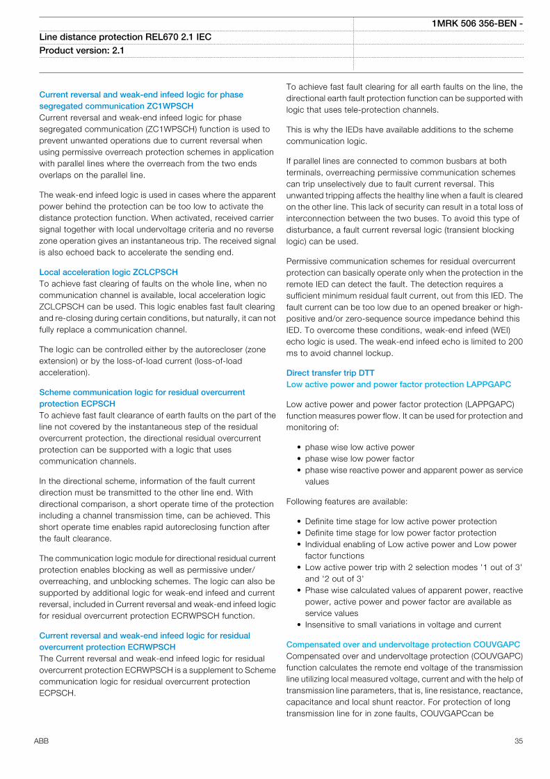
Current reversal and weak-end infeed logic for phasesegregated communication ZC1WPSCHCurrent reversal and weak-end infeed logic for phasesegregated communication (ZC1WPSCH) function is used toprevent unwanted operations due to current reversal whenusing permissive overreach protection schemes in applicationwith parallel lines where the overreach from the two endsoverlaps on the parallel line.
The weak-end infeed logic is used in cases where the apparentpower behind the protection can be too low to activate thedistance protection function. When activated, received carriersignal together with local undervoltage criteria and no reversezone operation gives an instantaneous trip. The received signalis also echoed back to accelerate the sending end.
Local acceleration logic ZCLCPSCHTo achieve fast clearing of faults on the whole line, when nocommunication channel is available, local acceleration logicZCLCPSCH can be used. This logic enables fast fault clearingand re-closing during certain conditions, but naturally, it can notfully replace a communication channel.
The logic can be controlled either by the autorecloser (zoneextension) or by the loss-of-load current (loss-of-loadacceleration).
Scheme communication logic for residual overcurrentprotection ECPSCHTo achieve fast fault clearance of earth faults on the part of theline not covered by the instantaneous step of the residualovercurrent protection, the directional residual overcurrentprotection can be supported with a logic that usescommunication channels.
In the directional scheme, information of the fault currentdirection must be transmitted to the other line end. Withdirectional comparison, a short operate time of the protectionincluding a channel transmission time, can be achieved. Thisshort operate time enables rapid autoreclosing function afterthe fault clearance.
The communication logic module for directional residual currentprotection enables blocking as well as permissive under/overreaching, and unblocking schemes. The logic can also besupported by additional logic for weak-end infeed and currentreversal, included in Current reversal and weak-end infeed logicfor residual overcurrent protection ECRWPSCH function.
Current reversal and weak-end infeed logic for residualovercurrent protection ECRWPSCHThe Current reversal and weak-end infeed logic for residualovercurrent protection ECRWPSCH is a supplement to Schemecommunication logic for residual overcurrent protectionECPSCH.
To achieve fast fault clearing for all earth faults on the line, thedirectional earth fault protection function can be supported withlogic that uses tele-protection channels.
This is why the IEDs have available additions to the schemecommunication logic.
If parallel lines are connected to common busbars at bothterminals, overreaching permissive communication schemescan trip unselectively due to fault current reversal. Thisunwanted tripping affects the healthy line when a fault is clearedon the other line. This lack of security can result in a total loss ofinterconnection between the two buses. To avoid this type ofdisturbance, a fault current reversal logic (transient blockinglogic) can be used.
Permissive communication schemes for residual overcurrentprotection can basically operate only when the protection in theremote IED can detect the fault. The detection requires asufficient minimum residual fault current, out from this IED. Thefault current can be too low due to an opened breaker or high-positive and/or zero-sequence source impedance behind thisIED. To overcome these conditions, weak-end infeed (WEI)echo logic is used. The weak-end infeed echo is limited to 200ms to avoid channel lockup.
Direct transfer trip DTTLow active power and power factor protection LAPPGAPC
Low active power and power factor protection (LAPPGAPC)function measures power flow. It can be used for protection andmonitoring of:
• phase wise low active power• phase wise low power factor• phase wise reactive power and apparent power as service
values
Following features are available:
• Definite time stage for low active power protection• Definite time stage for low power factor protection• Individual enabling of Low active power and Low power
factor functions• Low active power trip with 2 selection modes '1 out of 3'
and '2 out of 3'• Phase wise calculated values of apparent power, reactive
power, active power and power factor are available asservice values
• Insensitive to small variations in voltage and current
Compensated over and undervoltage protection COUVGAPCCompensated over and undervoltage protection (COUVGAPC)function calculates the remote end voltage of the transmissionline utilizing local measured voltage, current and with the help oftransmission line parameters, that is, line resistance, reactance,capacitance and local shunt reactor. For protection of longtransmission line for in zone faults, COUVGAPCcan be
1MRK 506 356-BEN -Line distance protection REL670 2.1 IEC Product version: 2.1
ABB 35
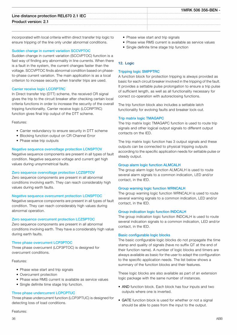
incorporated with local criteria within direct transfer trip logic toensure tripping of the line only under abnormal conditions.
Sudden change in current variation SCCVPTOCSudden change in current variation (SCCVPTOC) function is afast way of finding any abnormality in line currents. When thereis a fault in the system, the current changes faster than thevoltage. SCCVPTOC finds abnormal condition based on phase-to-phase current variation. The main application is as a localcriterion to increase security when transfer trips are used.
Carrier receive logic LCCRPTRCIn Direct transfer trip (DTT) scheme, the received CR signalgives the trip to the circuit breaker after checking certain localcriteria functions in order to increase the security of the overalltripping functionality. Carrier receive logic (LCCRPTRC)function gives final trip output of the DTT scheme.
Features:
• Carrier redundancy to ensure security in DTT scheme• Blocking function output on CR Channel Error• Phase wise trip outputs
Negative sequence overvoltage protection LCNSPTOVNegative sequence components are present in all types of faultcondition. Negative sequence voltage and current get highvalues during unsymmetrical faults.
Zero sequence overvoltage protection LCZSPTOVZero sequence components are present in all abnormalconditions involving earth. They can reach considerably highvalues during earth faults.
Negative sequence overcurrent protection LCNSPTOCNegative sequence components are present in all types of faultcondition. They can reach considerably high values duringabnormal operation.
Zero sequence overcurrent protection LCZSPTOCZero sequence components are present in all abnormalconditions involving earth. They have a considerably high valueduring earth faults.
Three phase overcurrent LCP3PTOCThree phase overcurrent (LCP3PTOC) is designed forovercurrent conditions.
Features:
• Phase wise start and trip signals• Overcurrent protection• Phase wise RMS current is available as service values• Single definite time stage trip function.
Three phase undercurrent LCPCPTUCThree phase undercurrent function (LCP3PTUC) is designed fordetecting loss of load conditions.
Features:
• Phase wise start and trip signals• Phase wise RMS current is available as service values• Single definite time stage trip function
12. Logic
Tripping logic SMPPTRCA function block for protection tripping is always provided asbasic for each circuit breaker involved in the tripping of the fault.It provides a settable pulse prolongation to ensure a trip pulseof sufficient length, as well as all functionality necessary forcorrect co-operation with autoreclosing functions.
The trip function block also includes a settable latchfunctionality for evolving faults and breaker lock-out.
Trip matrix logic TMAGAPCThe trip matrix logic TMAGAPC function is used to route tripsignals and other logical output signals to different outputcontacts on the IED.
The trip matrix logic function has 3 output signals and theseoutputs can be connected to physical tripping outputsaccording to the specific application needs for settable pulse orsteady output.
Group alarm logic function ALMCALHThe group alarm logic function ALMCALH is used to routeseveral alarm signals to a common indication, LED and/orcontact, in the IED.
Group warning logic function WRNCALHThe group warning logic function WRNCALH is used to routeseveral warning signals to a common indication, LED and/orcontact, in the IED.
Group indication logic function INDCALHThe group indication logic function INDCALH is used to routeseveral indication signals to a common indication, LED and/orcontact, in the IED.
Basic configurable logic blocksThe basic configurable logic blocks do not propagate the timestamp and quality of signals (have no suffix QT at the end oftheir function name). A number of logic blocks and timers arealways available as basic for the user to adapt the configurationto the specific application needs. The list below shows asummary of the function blocks and their features.
These logic blocks are also available as part of an extensionlogic package with the same number of instances.
• AND function block. Each block has four inputs and twooutputs where one is inverted.
• GATE function block is used for whether or not a signalshould be able to pass from the input to the output.
1MRK 506 356-BEN -Line distance protection REL670 2.1 IEC Product version: 2.1
36 ABB
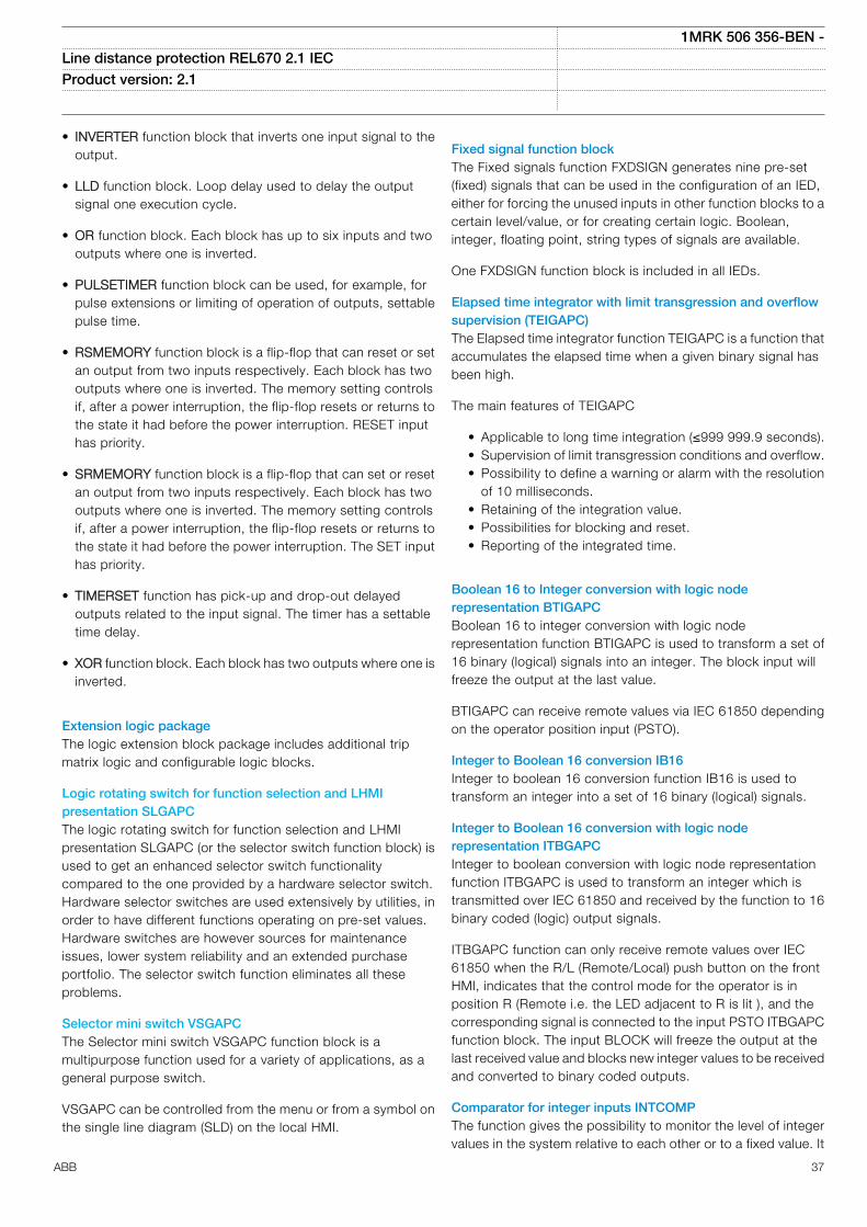
• INVERTER function block that inverts one input signal to theoutput.
• LLD function block. Loop delay used to delay the outputsignal one execution cycle.
• OR function block. Each block has up to six inputs and twooutputs where one is inverted.
• PULSETIMER function block can be used, for example, forpulse extensions or limiting of operation of outputs, settablepulse time.
• RSMEMORY function block is a flip-flop that can reset or setan output from two inputs respectively. Each block has twooutputs where one is inverted. The memory setting controlsif, after a power interruption, the flip-flop resets or returns tothe state it had before the power interruption. RESET inputhas priority.
• SRMEMORY function block is a flip-flop that can set or resetan output from two inputs respectively. Each block has twooutputs where one is inverted. The memory setting controlsif, after a power interruption, the flip-flop resets or returns tothe state it had before the power interruption. The SET inputhas priority.
• TIMERSET function has pick-up and drop-out delayedoutputs related to the input signal. The timer has a settabletime delay.
• XOR function block. Each block has two outputs where one isinverted.
Extension logic packageThe logic extension block package includes additional tripmatrix logic and configurable logic blocks.
Logic rotating switch for function selection and LHMIpresentation SLGAPCThe logic rotating switch for function selection and LHMIpresentation SLGAPC (or the selector switch function block) isused to get an enhanced selector switch functionalitycompared to the one provided by a hardware selector switch.Hardware selector switches are used extensively by utilities, inorder to have different functions operating on pre-set values.Hardware switches are however sources for maintenanceissues, lower system reliability and an extended purchaseportfolio. The selector switch function eliminates all theseproblems.
Selector mini switch VSGAPCThe Selector mini switch VSGAPC function block is amultipurpose function used for a variety of applications, as ageneral purpose switch.
VSGAPC can be controlled from the menu or from a symbol onthe single line diagram (SLD) on the local HMI.
Fixed signal function blockThe Fixed signals function FXDSIGN generates nine pre-set(fixed) signals that can be used in the configuration of an IED,either for forcing the unused inputs in other function blocks to acertain level/value, or for creating certain logic. Boolean,integer, floating point, string types of signals are available.
One FXDSIGN function block is included in all IEDs.
Elapsed time integrator with limit transgression and overflowsupervision (TEIGAPC)The Elapsed time integrator function TEIGAPC is a function thataccumulates the elapsed time when a given binary signal hasbeen high.
The main features of TEIGAPC
• Applicable to long time integration (≤999 999.9 seconds).• Supervision of limit transgression conditions and overflow.• Possibility to define a warning or alarm with the resolution
of 10 milliseconds.• Retaining of the integration value.• Possibilities for blocking and reset.• Reporting of the integrated time.
Boolean 16 to Integer conversion with logic noderepresentation BTIGAPCBoolean 16 to integer conversion with logic noderepresentation function BTIGAPC is used to transform a set of16 binary (logical) signals into an integer. The block input willfreeze the output at the last value.
BTIGAPC can receive remote values via IEC 61850 dependingon the operator position input (PSTO).
Integer to Boolean 16 conversion IB16Integer to boolean 16 conversion function IB16 is used totransform an integer into a set of 16 binary (logical) signals.
Integer to Boolean 16 conversion with logic noderepresentation ITBGAPCInteger to boolean conversion with logic node representationfunction ITBGAPC is used to transform an integer which istransmitted over IEC 61850 and received by the function to 16binary coded (logic) output signals.
ITBGAPC function can only receive remote values over IEC61850 when the R/L (Remote/Local) push button on the frontHMI, indicates that the control mode for the operator is inposition R (Remote i.e. the LED adjacent to R is lit ), and thecorresponding signal is connected to the input PSTO ITBGAPCfunction block. The input BLOCK will freeze the output at thelast received value and blocks new integer values to be receivedand converted to binary coded outputs.
Comparator for integer inputs INTCOMPThe function gives the possibility to monitor the level of integervalues in the system relative to each other or to a fixed value. It
1MRK 506 356-BEN -Line distance protection REL670 2.1 IEC Product version: 2.1
ABB 37
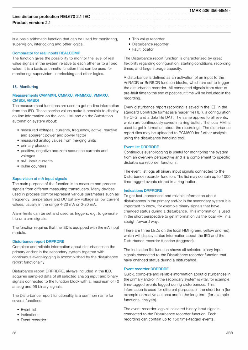
is a basic arithmetic function that can be used for monitoring,supervision, interlocking and other logics.
Comparator for real inputs REALCOMPThe function gives the possibility to monitor the level of realvalue signals in the system relative to each other or to a fixedvalue. It is a basic arithmetic function that can be used formonitoring, supervision, interlocking and other logics.
13. Monitoring
Measurements CVMMXN, CMMXU, VNMMXU, VMMXU,CMSQI, VMSQIThe measurement functions are used to get on-line informationfrom the IED. These service values make it possible to displayon-line information on the local HMI and on the Substationautomation system about:
• measured voltages, currents, frequency, active, reactiveand apparent power and power factor
• measured analog values from merging units• primary phasors• positive, negative and zero sequence currents and
voltages• mA, input currents• pulse counters
Supervision of mA input signalsThe main purpose of the function is to measure and processsignals from different measuring transducers. Many devicesused in process control represent various parameters such asfrequency, temperature and DC battery voltage as low currentvalues, usually in the range 4-20 mA or 0-20 mA.
Alarm limits can be set and used as triggers, e.g. to generatetrip or alarm signals.
The function requires that the IED is equipped with the mA inputmodule.
Disturbance report DRPRDREComplete and reliable information about disturbances in theprimary and/or in the secondary system together withcontinuous event-logging is accomplished by the disturbancereport functionality.
Disturbance report DRPRDRE, always included in the IED,acquires sampled data of all selected analog input and binarysignals connected to the function block with a, maximum of 40analog and 96 binary signals.
The Disturbance report functionality is a common name forseveral functions:
• Event list• Indications• Event recorder
• Trip value recorder• Disturbance recorder• Fault locator
The Disturbance report function is characterized by greatflexibility regarding configuration, starting conditions, recordingtimes, and large storage capacity.
A disturbance is defined as an activation of an input to theAnRADR or BnRBDR function blocks, which are set to triggerthe disturbance recorder. All connected signals from start ofpre-fault time to the end of post-fault time will be included in therecording.
Every disturbance report recording is saved in the IED in thestandard Comtrade format as a reader file HDR, a configurationfile CFG, and a data file DAT. The same applies to all events,which are continuously saved in a ring-buffer. The local HMI isused to get information about the recordings. The disturbancereport files may be uploaded to PCM600 for further analysisusing the disturbance handling tool.
Event list DRPRDREContinuous event-logging is useful for monitoring the systemfrom an overview perspective and is a complement to specificdisturbance recorder functions.
The event list logs all binary input signals connected to theDisturbance recorder function. The list may contain up to 1000time-tagged events stored in a ring-buffer.
Indications DRPRDRETo get fast, condensed and reliable information aboutdisturbances in the primary and/or in the secondary system it isimportant to know, for example binary signals that havechanged status during a disturbance. This information is usedin the short perspective to get information via the local HMI in astraightforward way.
There are three LEDs on the local HMI (green, yellow and red),which will display status information about the IED and theDisturbance recorder function (triggered).
The Indication list function shows all selected binary inputsignals connected to the Disturbance recorder function thathave changed status during a disturbance.
Event recorder DRPRDREQuick, complete and reliable information about disturbances inthe primary and/or in the secondary system is vital, for example,time-tagged events logged during disturbances. Thisinformation is used for different purposes in the short term (forexample corrective actions) and in the long term (for examplefunctional analysis).
The event recorder logs all selected binary input signalsconnected to the Disturbance recorder function. Eachrecording can contain up to 150 time-tagged events.
1MRK 506 356-BEN -Line distance protection REL670 2.1 IEC Product version: 2.1
38 ABB
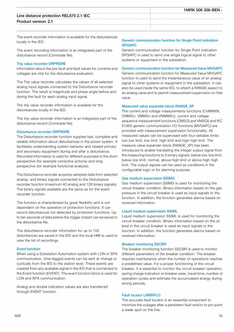
The event recorder information is available for the disturbanceslocally in the IED.
The event recording information is an integrated part of thedisturbance record (Comtrade file).
Trip value recorder DRPRDREInformation about the pre-fault and fault values for currents andvoltages are vital for the disturbance evaluation.
The Trip value recorder calculates the values of all selectedanalog input signals connected to the Disturbance recorderfunction. The result is magnitude and phase angle before andduring the fault for each analog input signal.
The trip value recorder information is available for thedisturbances locally in the IED.
The trip value recorder information is an integrated part of thedisturbance record (Comtrade file).
Disturbance recorder DRPRDREThe Disturbance recorder function supplies fast, complete andreliable information about disturbances in the power system. Itfacilitates understanding system behavior and related primaryand secondary equipment during and after a disturbance.Recorded information is used for different purposes in the shortperspective (for example corrective actions) and longperspective (for example functional analysis).
The Disturbance recorder acquires sampled data from selectedanalog- and binary signals connected to the Disturbancerecorder function (maximum 40 analog and 128 binary signals).The binary signals available are the same as for the eventrecorder function.
The function is characterized by great flexibility and is notdependent on the operation of protection functions. It canrecord disturbances not detected by protection functions. Upto ten seconds of data before the trigger instant can be saved inthe disturbance file.
The disturbance recorder information for up to 100disturbances are saved in the IED and the local HMI is used toview the list of recordings.
Event functionWhen using a Substation Automation system with LON or SPAcommunication, time-tagged events can be sent at change orcyclically from the IED to the station level. These events arecreated from any available signal in the IED that is connected tothe Event function (EVENT). The event function block is used forLON and SPA communication.
Analog and double indication values are also transferredthrough EVENT function.
Generic communication function for Single Point indicationSPGAPCGeneric communication function for Single Point indicationSPGAPC is used to send one single logical signal to othersystems or equipment in the substation.
Generic communication function for Measured Value MVGAPCGeneric communication function for Measured Value MVGAPCfunction is used to send the instantaneous value of an analogsignal to other systems or equipment in the substation. It canalso be used inside the same IED, to attach a RANGE aspect toan analog value and to permit measurement supervision on thatvalue.
Measured value expander block RANGE_XPThe current and voltage measurements functions (CVMMXN,CMMXU, VMMXU and VNMMXU), current and voltagesequence measurement functions (CMSQI and VMSQI) and IEC61850 generic communication I/O functions (MVGAPC) areprovided with measurement supervision functionality. Allmeasured values can be supervised with four settable limits:low-low limit, low limit, high limit and high-high limit. Themeasure value expander block (RANGE_XP) has beenintroduced to enable translating the integer output signal fromthe measuring functions to 5 binary signals: below low-low limit,below low limit, normal, above high limit or above high-highlimit. The output signals can be used as conditions in theconfigurable logic or for alarming purpose.
Gas medium supervision SSIMGGas medium supervision SSIMG is used for monitoring thecircuit breaker condition. Binary information based on the gaspressure in the circuit breaker is used as input signals to thefunction. In addition, the function generates alarms based onreceived information.
Liquid medium supervision SSIMLLiquid medium supervision SSIML is used for monitoring thecircuit breaker condition. Binary information based on the oillevel in the circuit breaker is used as input signals to thefunction. In addition, the function generates alarms based onreceived information.
Breaker monitoring SSCBRThe breaker monitoring function SSCBR is used to monitordifferent parameters of the breaker condition. The breakerrequires maintenance when the number of operations reachesa predefined value. For a proper functioning of the circuitbreaker, it is essential to monitor the circuit breaker operation,spring charge indication or breaker wear, travel time, number ofoperation cycles and estimate the accumulated energy duringarcing periods.
Fault locator LMBRFLOThe accurate fault locator is an essential component tominimize the outages after a persistent fault and/or to pin-pointa weak spot on the line.
1MRK 506 356-BEN -Line distance protection REL670 2.1 IEC Product version: 2.1
ABB 39
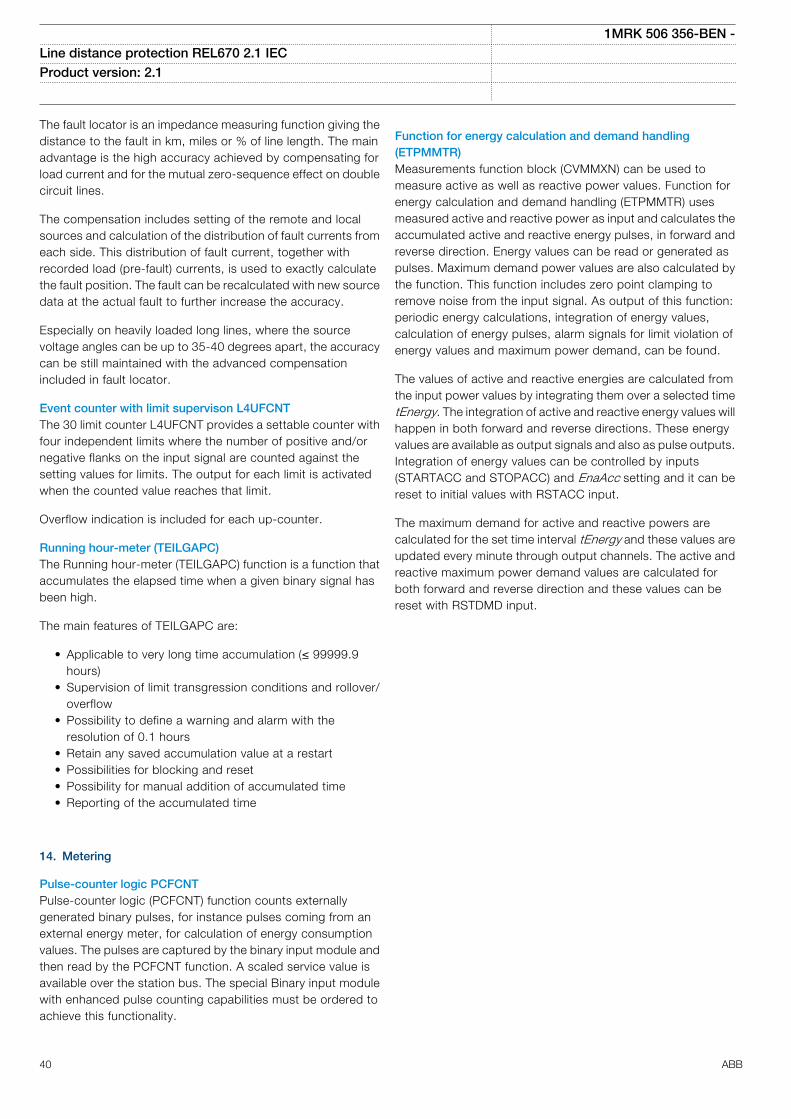
The fault locator is an impedance measuring function giving thedistance to the fault in km, miles or % of line length. The mainadvantage is the high accuracy achieved by compensating forload current and for the mutual zero-sequence effect on doublecircuit lines.
The compensation includes setting of the remote and localsources and calculation of the distribution of fault currents fromeach side. This distribution of fault current, together withrecorded load (pre-fault) currents, is used to exactly calculatethe fault position. The fault can be recalculated with new sourcedata at the actual fault to further increase the accuracy.
Especially on heavily loaded long lines, where the sourcevoltage angles can be up to 35-40 degrees apart, the accuracycan be still maintained with the advanced compensationincluded in fault locator.
Event counter with limit supervison L4UFCNTThe 30 limit counter L4UFCNT provides a settable counter withfour independent limits where the number of positive and/ornegative flanks on the input signal are counted against thesetting values for limits. The output for each limit is activatedwhen the counted value reaches that limit.
Overflow indication is included for each up-counter.
Running hour-meter (TEILGAPC)The Running hour-meter (TEILGAPC) function is a function thataccumulates the elapsed time when a given binary signal hasbeen high.
The main features of TEILGAPC are:
• Applicable to very long time accumulation (≤ 99999.9hours)
• Supervision of limit transgression conditions and rollover/overflow
• Possibility to define a warning and alarm with theresolution of 0.1 hours
• Retain any saved accumulation value at a restart• Possibilities for blocking and reset• Possibility for manual addition of accumulated time• Reporting of the accumulated time
14. Metering
Pulse-counter logic PCFCNTPulse-counter logic (PCFCNT) function counts externallygenerated binary pulses, for instance pulses coming from anexternal energy meter, for calculation of energy consumptionvalues. The pulses are captured by the binary input module andthen read by the PCFCNT function. A scaled service value isavailable over the station bus. The special Binary input modulewith enhanced pulse counting capabilities must be ordered toachieve this functionality.
Function for energy calculation and demand handling(ETPMMTR)Measurements function block (CVMMXN) can be used tomeasure active as well as reactive power values. Function forenergy calculation and demand handling (ETPMMTR) usesmeasured active and reactive power as input and calculates theaccumulated active and reactive energy pulses, in forward andreverse direction. Energy values can be read or generated aspulses. Maximum demand power values are also calculated bythe function. This function includes zero point clamping toremove noise from the input signal. As output of this function:periodic energy calculations, integration of energy values,calculation of energy pulses, alarm signals for limit violation ofenergy values and maximum power demand, can be found.
The values of active and reactive energies are calculated fromthe input power values by integrating them over a selected timetEnergy. The integration of active and reactive energy values willhappen in both forward and reverse directions. These energyvalues are available as output signals and also as pulse outputs.Integration of energy values can be controlled by inputs(STARTACC and STOPACC) and EnaAcc setting and it can bereset to initial values with RSTACC input.
The maximum demand for active and reactive powers arecalculated for the set time interval tEnergy and these values areupdated every minute through output channels. The active andreactive maximum power demand values are calculated forboth forward and reverse direction and these values can bereset with RSTDMD input.
1MRK 506 356-BEN -Line distance protection REL670 2.1 IEC Product version: 2.1
40 ABB
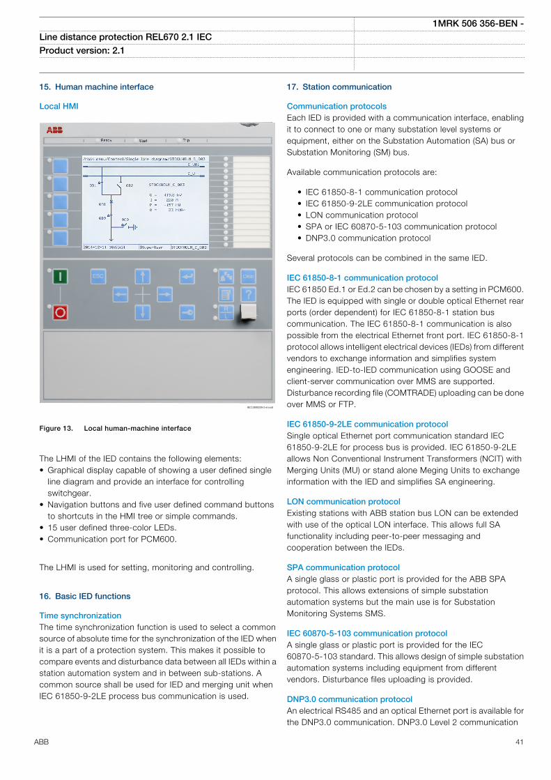
15. Human machine interface
Local HMI
IEC13000239-2-en.vsd
IEC13000239 V2 EN
Figure 13. Local human-machine interface
The LHMI of the IED contains the following elements:• Graphical display capable of showing a user defined single
line diagram and provide an interface for controllingswitchgear.
• Navigation buttons and five user defined command buttonsto shortcuts in the HMI tree or simple commands.
• 15 user defined three-color LEDs.• Communication port for PCM600.
The LHMI is used for setting, monitoring and controlling.
16. Basic IED functions
Time synchronizationThe time synchronization function is used to select a commonsource of absolute time for the synchronization of the IED whenit is a part of a protection system. This makes it possible tocompare events and disturbance data between all IEDs within astation automation system and in between sub-stations. Acommon source shall be used for IED and merging unit whenIEC 61850-9-2LE process bus communication is used.
17. Station communication
Communication protocolsEach IED is provided with a communication interface, enablingit to connect to one or many substation level systems orequipment, either on the Substation Automation (SA) bus orSubstation Monitoring (SM) bus.
Available communication protocols are:
• IEC 61850-8-1 communication protocol• IEC 61850-9-2LE communication protocol• LON communication protocol• SPA or IEC 60870-5-103 communication protocol• DNP3.0 communication protocol
Several protocols can be combined in the same IED.
IEC 61850-8-1 communication protocolIEC 61850 Ed.1 or Ed.2 can be chosen by a setting in PCM600.The IED is equipped with single or double optical Ethernet rearports (order dependent) for IEC 61850-8-1 station buscommunication. The IEC 61850-8-1 communication is alsopossible from the electrical Ethernet front port. IEC 61850-8-1protocol allows intelligent electrical devices (IEDs) from differentvendors to exchange information and simplifies systemengineering. IED-to-IED communication using GOOSE andclient-server communication over MMS are supported.Disturbance recording file (COMTRADE) uploading can be doneover MMS or FTP.
IEC 61850-9-2LE communication protocolSingle optical Ethernet port communication standard IEC61850-9-2LE for process bus is provided. IEC 61850-9-2LEallows Non Conventional Instrument Transformers (NCIT) withMerging Units (MU) or stand alone Meging Units to exchangeinformation with the IED and simplifies SA engineering.
LON communication protocolExisting stations with ABB station bus LON can be extendedwith use of the optical LON interface. This allows full SAfunctionality including peer-to-peer messaging andcooperation between the IEDs.
SPA communication protocolA single glass or plastic port is provided for the ABB SPAprotocol. This allows extensions of simple substationautomation systems but the main use is for SubstationMonitoring Systems SMS.
IEC 60870-5-103 communication protocolA single glass or plastic port is provided for the IEC60870-5-103 standard. This allows design of simple substationautomation systems including equipment from differentvendors. Disturbance files uploading is provided.
DNP3.0 communication protocolAn electrical RS485 and an optical Ethernet port is available forthe DNP3.0 communication. DNP3.0 Level 2 communication
1MRK 506 356-BEN -Line distance protection REL670 2.1 IEC Product version: 2.1
ABB 41
with unsolicited events, time synchronizing and disturbancereporting is provided for communication to RTUs, Gateways orHMI systems.
Multiple command and transmitWhen IEDs are used in Substation Automation systems withLON, SPA or IEC 60870-5-103 communication protocols, theEvent and Multiple Command function blocks are used as thecommunication interface for vertical communication to stationHMI and gateway, and as interface for horizontal peer-to-peercommunication (over LON only).
IEC 62439-3 Parallel Redundancy ProtocolRedundant station bus communication according to IEC62439-3 Edition 1 and IEC 62439-3 Edition 2 parallelredundancy protocol (PRP) are available as options whenordering IEDs. Redundant station bus communicationaccording to IEC 62439-3 uses both port AB and port CD onthe OEM module.
18. Remote communication
Analog and binary signal transfer to remote endThree analog and eight binary signals can be exchangedbetween two IEDs. This functionality is mainly used for the linedifferential protection. However it can be used in other productsas well. An IED can communicate with up to 4 remote IEDs.
Binary signal transfer to remote end, 192 signalsIf the communication channel is used for transfer of binarysignals only, up to 192 binary signals can be exchangedbetween two IEDs. For example, this functionality can be usedto send information such as status of primary switchgearapparatus or intertripping signals to the remote IED. An IED cancommunicate with up to 4 remote IEDs.
Line data communication module, short, medium and longrange LDCMThe line data communication module (LDCM) is used forcommunication between the IEDs situated at distances <110km/68 miles or from the IED to optical to electrical converterwith G.703 or G.703E1 interface located on a distances < 3km/1.9 miles away. The LDCM module sends and receivesdata, to and from another LDCM module. The IEEE/ANSIC37.94 standard format is used.
Galvanic X.21 line data communication module X.21-LDCMA module with built-in galvanic X.21 converter which e.g. canbe connected to modems for pilot wires is also available.
Galvanic interface G.703 resp G.703E1The external galvanic data communication converter G.703/G.703E1 makes an optical-to-galvanic conversion for connectionto a multiplexer. These units are designed for 64 kbit/s resp2Mbit/s operation. The converter is delivered with 19” rackmounting accessories.
19. Hardware description
Hardware modulesPower supply module PSMThe power supply module is used to provide the correct internalvoltages and full isolation between the IED and the batterysystem. An internal fail alarm output is available.
Binary input module BIMThe binary input module has 16 optically isolated inputs and isavailable in two versions, one standard and one with enhancedpulse counting capabilities on the inputs to be used with thepulse counter function. The binary inputs are freelyprogrammable and can be used for the input of logical signalsto any of the functions. They can also be included in thedisturbance recording and event-recording functions. Thisenables extensive monitoring and evaluation of operation of theIED and for all associated electrical circuits.
Binary output module BOMThe binary output module has 24 independent output relaysand is used for trip output or any signaling purpose.
Static binary output module SOMThe static binary output module has six fast static outputs andsix change over output relays for use in applications with highspeed requirements.
Binary input/output module IOMThe binary input/output module is used when only a few inputand output channels are needed. The ten standard outputchannels are used for trip output or any signaling purpose. Thetwo high speed signal output channels are used for applicationswhere short operating time is essential. Eight optically isolatedbinary inputs cater for required binary input information.
mA input module MIMThe milli-ampere input module is used to interface transducersignals in the –20 to +20 mA range from for example OLTCposition, temperature or pressure transducers. The module hassix independent, galvanically separated channels.
Optical ethernet module OEMThe optical fast-ethernet module is used for fast andinterference-free communication of synchrophasor data overIEEE C37.118 and/or IEEE 1344 protocols. It is also used toconnect an IED to the communication buses (like the stationbus) that use the IEC 61850-8-1 protocol (OEM rear port A, B).The process bus use the IEC 61850-9-2LE protocol (OEM rearport C, D). The module has one or two optical ports with STconnectors.
Serial and LON communication module SLM, supportsSPA/IEC 60870-5-103, LON and DNP 3.0The serial and LON communication module (SLM) is used forSPA, IEC 60870-5-103, DNP3 and LON communication. Themodule has two optical communication ports for plastic/plastic,plastic/glass or glass/glass. One port is used for serial
1MRK 506 356-BEN -Line distance protection REL670 2.1 IEC Product version: 2.1
42 ABB
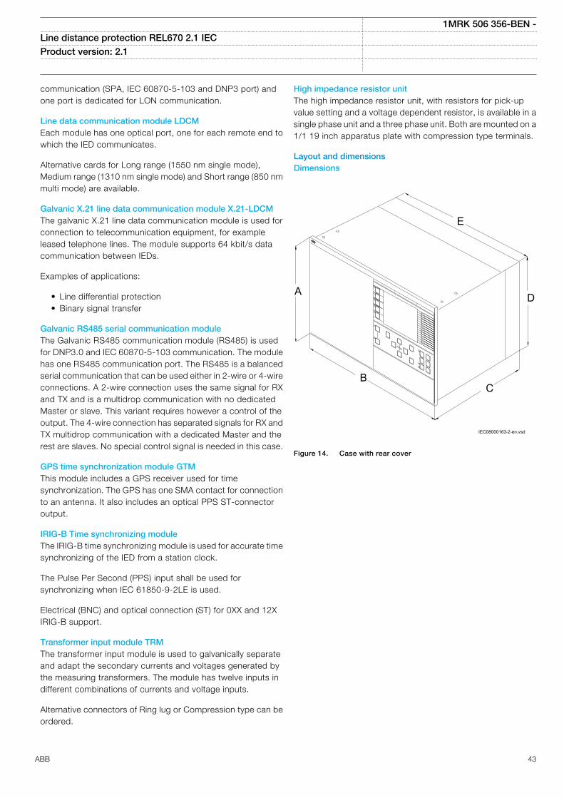
communication (SPA, IEC 60870-5-103 and DNP3 port) andone port is dedicated for LON communication.
Line data communication module LDCMEach module has one optical port, one for each remote end towhich the IED communicates.
Alternative cards for Long range (1550 nm single mode),Medium range (1310 nm single mode) and Short range (850 nmmulti mode) are available.
Galvanic X.21 line data communication module X.21-LDCMThe galvanic X.21 line data communication module is used forconnection to telecommunication equipment, for exampleleased telephone lines. The module supports 64 kbit/s datacommunication between IEDs.
Examples of applications:
• Line differential protection• Binary signal transfer
Galvanic RS485 serial communication moduleThe Galvanic RS485 communication module (RS485) is usedfor DNP3.0 and IEC 60870-5-103 communication. The modulehas one RS485 communication port. The RS485 is a balancedserial communication that can be used either in 2-wire or 4-wireconnections. A 2-wire connection uses the same signal for RXand TX and is a multidrop communication with no dedicatedMaster or slave. This variant requires however a control of theoutput. The 4-wire connection has separated signals for RX andTX multidrop communication with a dedicated Master and therest are slaves. No special control signal is needed in this case.
GPS time synchronization module GTMThis module includes a GPS receiver used for timesynchronization. The GPS has one SMA contact for connectionto an antenna. It also includes an optical PPS ST-connectoroutput.
IRIG-B Time synchronizing moduleThe IRIG-B time synchronizing module is used for accurate timesynchronizing of the IED from a station clock.
The Pulse Per Second (PPS) input shall be used forsynchronizing when IEC 61850-9-2LE is used.
Electrical (BNC) and optical connection (ST) for 0XX and 12XIRIG-B support.
Transformer input module TRMThe transformer input module is used to galvanically separateand adapt the secondary currents and voltages generated bythe measuring transformers. The module has twelve inputs indifferent combinations of currents and voltage inputs.
Alternative connectors of Ring lug or Compression type can beordered.
High impedance resistor unitThe high impedance resistor unit, with resistors for pick-upvalue setting and a voltage dependent resistor, is available in asingle phase unit and a three phase unit. Both are mounted on a1/1 19 inch apparatus plate with compression type terminals.
Layout and dimensionsDimensions
CB
D
E
A
IEC08000163-2-en.vsd
IEC08000163 V2 EN
Figure 14. Case with rear cover
1MRK 506 356-BEN -Line distance protection REL670 2.1 IEC Product version: 2.1
ABB 43
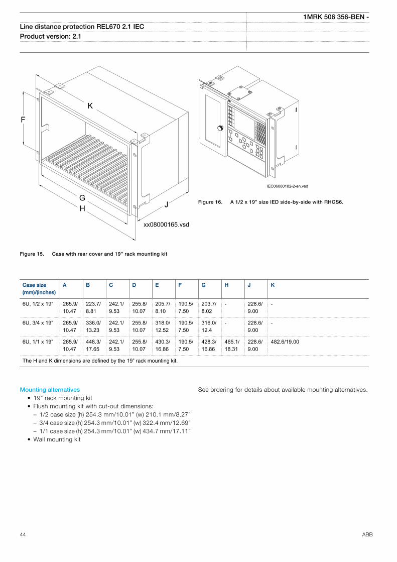
xx08000165.vsd
JG
F
K
H
IEC08000165 V1 EN
Figure 15. Case with rear cover and 19” rack mounting kit
IEC06000182-2-en.vsdIEC06000182 V2 EN
Figure 16. A 1/2 x 19” size IED side-by-side with RHGS6.
Case size(mm)/(inches)
A B C D E F G H J K
6U, 1/2 x 19” 265.9/10.47
223.7/8.81
242.1/9.53
255.8/10.07
205.7/8.10
190.5/7.50
203.7/8.02
- 228.6/9.00
-
6U, 3/4 x 19” 265.9/10.47
336.0/13.23
242.1/9.53
255.8/10.07
318.0/12.52
190.5/7.50
316.0/12.4
- 228.6/9.00
-
6U, 1/1 x 19” 265.9/10.47
448.3/17.65
242.1/9.53
255.8/10.07
430.3/16.86
190.5/7.50
428.3/16.86
465.1/18.31
228.6/9.00
482.6/19.00
The H and K dimensions are defined by the 19” rack mounting kit.
Mounting alternatives• 19” rack mounting kit• Flush mounting kit with cut-out dimensions:
– 1/2 case size (h) 254.3 mm/10.01” (w) 210.1 mm/8.27”– 3/4 case size (h) 254.3 mm/10.01” (w) 322.4 mm/12.69”– 1/1 case size (h) 254.3 mm/10.01” (w) 434.7 mm/17.11”
• Wall mounting kit
See ordering for details about available mounting alternatives.
1MRK 506 356-BEN -Line distance protection REL670 2.1 IEC Product version: 2.1
44 ABB

20. Connection diagrams
Connection diagramsThe connection diagrams are delivered on the IED Connectivitypackage DVD as part of the product delivery.
The latest versions of the connection diagrams can bedownloaded from http://www.abb.com/substationautomation.
Connection diagrams for Customized products
Connection diagram, 670 series 2.11MRK002801-AF
Connection diagrams for Configured products
Connection diagram, REL670 2.1, A21 1MRK002803-ME
Connection diagram, REL670 2.1, A31 1MRK002803-MA
Connection diagram, REL670 2.1, B31 1MRK002803-MB
Connection diagram, REL670 2.1, A32 1MRK002803-MC
Connection diagram, REL670 2.1, B32 1MRK002803-MD
Connection diagrams for Customized products
Connection diagram, 670 series 2.1 1MRK002802-AF
1MRK 506 356-BEN -Line distance protection REL670 2.1 IEC Product version: 2.1
ABB 45
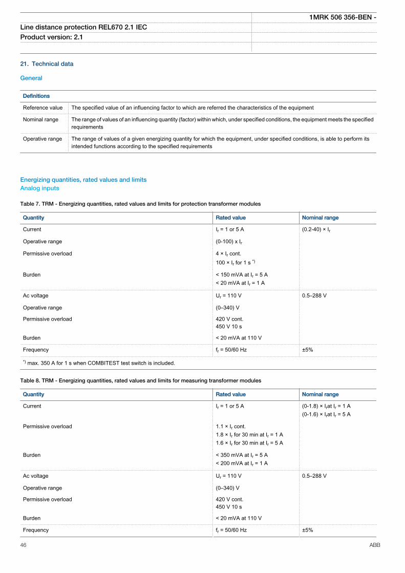
21. Technical data
General
Definitions
Reference value The specified value of an influencing factor to which are referred the characteristics of the equipment
Nominal range The range of values of an influencing quantity (factor) within which, under specified conditions, the equipment meets the specifiedrequirements
Operative range The range of values of a given energizing quantity for which the equipment, under specified conditions, is able to perform itsintended functions according to the specified requirements
Energizing quantities, rated values and limitsAnalog inputs
Table 7. TRM - Energizing quantities, rated values and limits for protection transformer modules
Quantity Rated value Nominal range
Current Ir = 1 or 5 A (0.2-40) × Ir
Operative range (0-100) x Ir
Permissive overload 4 × Ir cont.100 × Ir for 1 s *)
Burden < 150 mVA at Ir = 5 A< 20 mVA at Ir = 1 A
Ac voltage Ur = 110 V 0.5–288 V
Operative range (0–340) V
Permissive overload 420 V cont.450 V 10 s
Burden < 20 mVA at 110 V
Frequency fr = 50/60 Hz ±5%
*) max. 350 A for 1 s when COMBITEST test switch is included.
Table 8. TRM - Energizing quantities, rated values and limits for measuring transformer modules
Quantity Rated value Nominal range
Current Ir = 1 or 5 A (0-1.8) × Irat Ir = 1 A(0-1.6) × Irat Ir = 5 A
Permissive overload 1.1 × Ir cont.1.8 × Ir for 30 min at Ir = 1 A1.6 × Ir for 30 min at Ir = 5 A
Burden < 350 mVA at Ir = 5 A< 200 mVA at Ir = 1 A
Ac voltage Ur = 110 V 0.5–288 V
Operative range (0–340) V
Permissive overload 420 V cont.450 V 10 s
Burden < 20 mVA at 110 V
Frequency fr = 50/60 Hz ±5%
1MRK 506 356-BEN -Line distance protection REL670 2.1 IEC Product version: 2.1
46 ABB
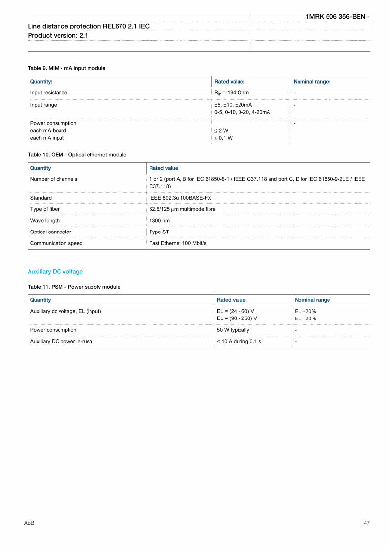
Table 9. MIM - mA input module
Quantity: Rated value: Nominal range:
Input resistance Rin = 194 Ohm -
Input range ±5, ±10, ±20mA0-5, 0-10, 0-20, 4-20mA
-
Power consumptioneach mA-boardeach mA input
£ 2 W£ 0.1 W
-
Table 10. OEM - Optical ethernet module
Quantity Rated value
Number of channels 1 or 2 (port A, B for IEC 61850-8-1 / IEEE C37.118 and port C, D for IEC 61850-9-2LE / IEEEC37.118)
Standard IEEE 802.3u 100BASE-FX
Type of fiber 62.5/125 mm multimode fibre
Wave length 1300 nm
Optical connector Type ST
Communication speed Fast Ethernet 100 Mbit/s
Auxiliary DC voltage
Table 11. PSM - Power supply module
Quantity Rated value Nominal range
Auxiliary dc voltage, EL (input) EL = (24 - 60) VEL = (90 - 250) V
EL ±20%EL ±20%
Power consumption 50 W typically -
Auxiliary DC power in-rush < 10 A during 0.1 s -
1MRK 506 356-BEN -Line distance protection REL670 2.1 IEC Product version: 2.1
ABB 47
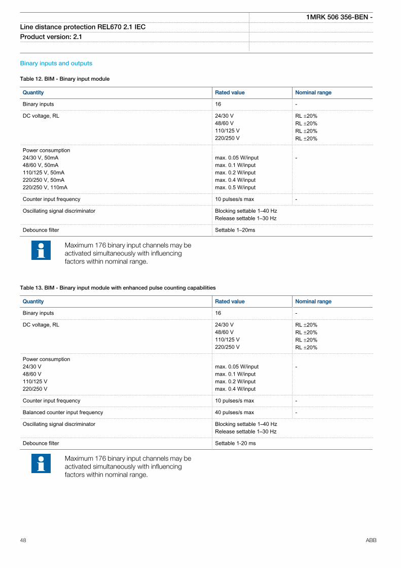
Binary inputs and outputs
Table 12. BIM - Binary input module
Quantity Rated value Nominal range
Binary inputs 16 -
DC voltage, RL 24/30 V48/60 V110/125 V220/250 V
RL ±20%RL ±20%RL ±20%RL ±20%
Power consumption24/30 V, 50mA48/60 V, 50mA110/125 V, 50mA220/250 V, 50mA220/250 V, 110mA
max. 0.05 W/inputmax. 0.1 W/inputmax. 0.2 W/inputmax. 0.4 W/inputmax. 0.5 W/input
-
Counter input frequency 10 pulses/s max -
Oscillating signal discriminator Blocking settable 1–40 HzRelease settable 1–30 Hz
Debounce filter Settable 1–20ms
Maximum 176 binary input channels may beactivated simultaneously with influencingfactors within nominal range.
Table 13. BIM - Binary input module with enhanced pulse counting capabilities
Quantity Rated value Nominal range
Binary inputs 16 -
DC voltage, RL 24/30 V48/60 V110/125 V220/250 V
RL ±20%RL ±20%RL ±20%RL ±20%
Power consumption24/30 V48/60 V110/125 V220/250 V
max. 0.05 W/inputmax. 0.1 W/inputmax. 0.2 W/inputmax. 0.4 W/input
-
Counter input frequency 10 pulses/s max -
Balanced counter input frequency 40 pulses/s max -
Oscillating signal discriminator Blocking settable 1–40 HzRelease settable 1–30 Hz
Debounce filter Settable 1-20 ms
Maximum 176 binary input channels may beactivated simultaneously with influencingfactors within nominal range.
1MRK 506 356-BEN -Line distance protection REL670 2.1 IEC Product version: 2.1
48 ABB
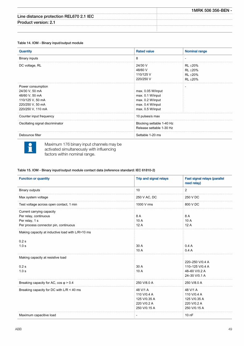
Table 14. IOM - Binary input/output module
Quantity Rated value Nominal range
Binary inputs 8 -
DC voltage, RL 24/30 V48/60 V110/125 V220/250 V
RL ±20%RL ±20%RL ±20%RL ±20%
Power consumption24/30 V, 50 mA48/60 V, 50 mA110/125 V, 50 mA220/250 V, 50 mA220/250 V, 110 mA
max. 0.05 W/inputmax. 0.1 W/inputmax. 0.2 W/inputmax. 0.4 W/inputmax. 0.5 W/input
-
Counter input frequency 10 pulses/s max
Oscillating signal discriminator Blocking settable 1-40 HzRelease settable 1-30 Hz
Debounce filter Settable 1-20 ms
Maximum 176 binary input channels may beactivated simultaneously with influencingfactors within nominal range.
Table 15. IOM - Binary input/output module contact data (reference standard: IEC 61810-2)
Function or quantity Trip and signal relays Fast signal relays (parallelreed relay)
Binary outputs 10 2
Max system voltage 250 V AC, DC 250 V DC
Test voltage across open contact, 1 min 1000 V rms 800 V DC
Current carrying capacityPer relay, continuousPer relay, 1 sPer process connector pin, continuous
8 A10 A12 A
8 A10 A12 A
Making capacity at inductive load with L/R>10 ms 0.2 s1.0 s
30 A10 A
0.4 A0.4 A
Making capacity at resistive load 0.2 s1.0 s
30 A10 A
220–250 V/0.4 A110–125 V/0.4 A48–60 V/0.2 A24–30 V/0.1 A
Breaking capacity for AC, cos φ > 0.4 250 V/8.0 A 250 V/8.0 A
Breaking capacity for DC with L/R < 40 ms 48 V/1 A110 V/0.4 A125 V/0.35 A220 V/0.2 A250 V/0.15 A
48 V/1 A110 V/0.4 A125 V/0.35 A220 V/0.2 A250 V/0.15 A
Maximum capacitive load - 10 nF
1MRK 506 356-BEN -Line distance protection REL670 2.1 IEC Product version: 2.1
ABB 49
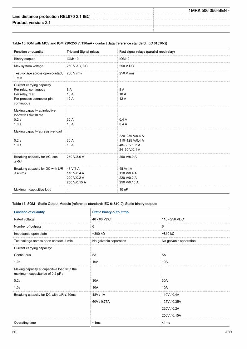
Table 16. IOM with MOV and IOM 220/250 V, 110mA - contact data (reference standard: IEC 61810-2)
Function or quantity Trip and Signal relays Fast signal relays (parallel reed relay)
Binary outputs IOM: 10 IOM: 2
Max system voltage 250 V AC, DC 250 V DC
Test voltage across open contact,1 min
250 V rms 250 V rms
Current carrying capacityPer relay, continuousPer relay, 1 sPer process connector pin,continuous
8 A10 A12 A
8 A10 A12 A
Making capacity at inductiveloadwith L/R>10 ms0.2 s1.0 s
30 A10 A
0.4 A0.4 A
Making capacity at resistive load 0.2 s1.0 s
30 A10 A
220–250 V/0.4 A110–125 V/0.4 A48–60 V/0.2 A24–30 V/0.1 A
Breaking capacity for AC, cosj>0.4
250 V/8.0 A 250 V/8.0 A
Breaking capacity for DC with L/R< 40 ms
48 V/1 A110 V/0.4 A220 V/0.2 A250 V/0.15 A
48 V/1 A110 V/0.4 A220 V/0.2 A250 V/0.15 A
Maximum capacitive load - 10 nF
Table 17. SOM - Static Output Module (reference standard: IEC 61810-2): Static binary outputs
Function of quantity Static binary output trip
Rated voltage 48 - 60 VDC 110 - 250 VDC
Number of outputs 6 6
Impedance open state ~300 kΩ ~810 kΩ
Test voltage across open contact, 1 min No galvanic separation No galvanic separation
Current carrying capacity:
Continuous 5A 5A
1.0s 10A 10A
Making capacity at capacitive load with themaximum capacitance of 0.2 μF :
0.2s 30A 30A
1.0s 10A 10A
Breaking capacity for DC with L/R ≤ 40ms 48V / 1A 110V / 0.4A
60V / 0.75A 125V / 0.35A
220V / 0.2A
250V / 0.15A
Operating time <1ms <1ms
1MRK 506 356-BEN -Line distance protection REL670 2.1 IEC Product version: 2.1
50 ABB
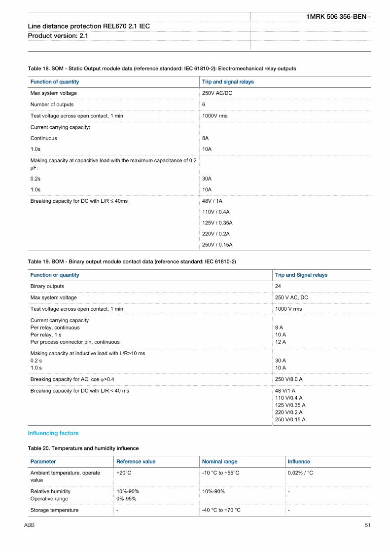
Table 18. SOM - Static Output module data (reference standard: IEC 61810-2): Electromechanical relay outputs
Function of quantity Trip and signal relays
Max system voltage 250V AC/DC
Number of outputs 6
Test voltage across open contact, 1 min 1000V rms
Current carrying capacity:
Continuous 8A
1.0s 10A
Making capacity at capacitive load with the maximum capacitance of 0.2μF:
0.2s 30A
1.0s 10A
Breaking capacity for DC with L/R ≤ 40ms 48V / 1A
110V / 0.4A
125V / 0.35A
220V / 0.2A
250V / 0.15A
Table 19. BOM - Binary output module contact data (reference standard: IEC 61810-2)
Function or quantity Trip and Signal relays
Binary outputs 24
Max system voltage 250 V AC, DC
Test voltage across open contact, 1 min 1000 V rms
Current carrying capacityPer relay, continuousPer relay, 1 sPer process connector pin, continuous
8 A10 A12 A
Making capacity at inductive load with L/R>10 ms0.2 s1.0 s
30 A10 A
Breaking capacity for AC, cos j>0.4 250 V/8.0 A
Breaking capacity for DC with L/R < 40 ms 48 V/1 A110 V/0.4 A125 V/0.35 A220 V/0.2 A250 V/0.15 A
Influencing factors
Table 20. Temperature and humidity influence
Parameter Reference value Nominal range Influence
Ambient temperature, operatevalue
+20°C -10 °C to +55°C 0.02% / °C
Relative humidityOperative range
10%-90%0%-95%
10%-90% -
Storage temperature - -40 °C to +70 °C -
1MRK 506 356-BEN -Line distance protection REL670 2.1 IEC Product version: 2.1
ABB 51
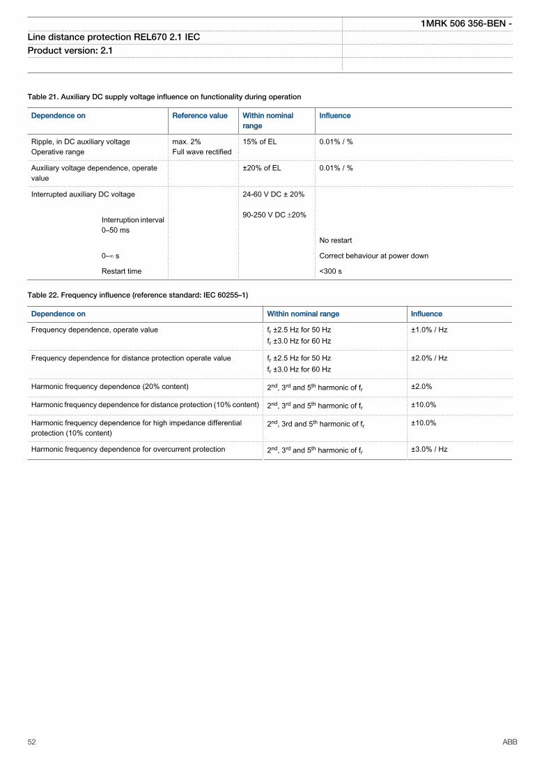
Table 21. Auxiliary DC supply voltage influence on functionality during operation
Dependence on Reference value Within nominalrange
Influence
Ripple, in DC auxiliary voltageOperative range
max. 2%Full wave rectified
15% of EL 0.01% / %
Auxiliary voltage dependence, operatevalue
±20% of EL 0.01% / %
Interrupted auxiliary DC voltage
24-60 V DC ± 20% 90-250 V DC ±20%
Interruption interval0–50 ms
No restart
0–∞ s Correct behaviour at power down
Restart time <300 s
Table 22. Frequency influence (reference standard: IEC 60255–1)
Dependence on Within nominal range Influence
Frequency dependence, operate value fr ±2.5 Hz for 50 Hzfr ±3.0 Hz for 60 Hz
±1.0% / Hz
Frequency dependence for distance protection operate value fr ±2.5 Hz for 50 Hzfr ±3.0 Hz for 60 Hz
±2.0% / Hz
Harmonic frequency dependence (20% content) 2nd, 3rd and 5th harmonic of fr ±2.0%
Harmonic frequency dependence for distance protection (10% content) 2nd, 3rd and 5th harmonic of fr ±10.0%
Harmonic frequency dependence for high impedance differentialprotection (10% content)
2nd, 3rd and 5th harmonic of fr ±10.0%
Harmonic frequency dependence for overcurrent protection 2nd, 3rd and 5th harmonic of fr ±3.0% / Hz
1MRK 506 356-BEN -Line distance protection REL670 2.1 IEC Product version: 2.1
52 ABB
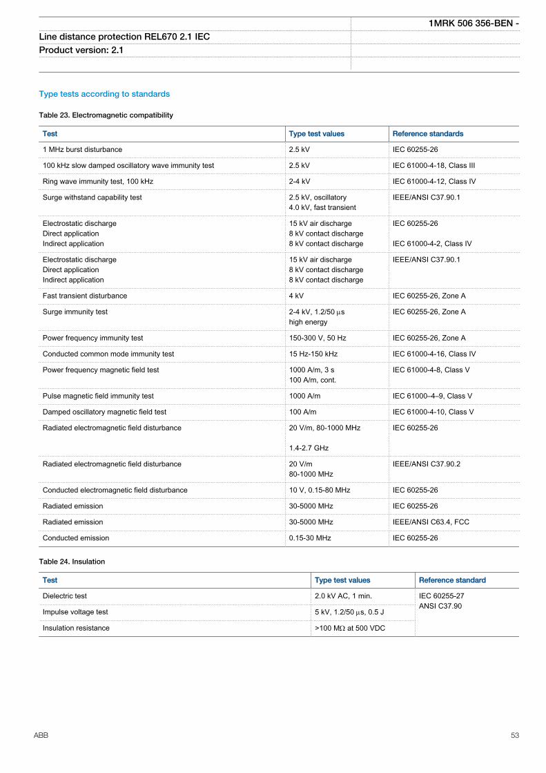
Type tests according to standards
Table 23. Electromagnetic compatibility
Test Type test values Reference standards
1 MHz burst disturbance 2.5 kV IEC 60255-26
100 kHz slow damped oscillatory wave immunity test 2.5 kV IEC 61000-4-18, Class III
Ring wave immunity test, 100 kHz 2-4 kV IEC 61000-4-12, Class IV
Surge withstand capability test 2.5 kV, oscillatory4.0 kV, fast transient
IEEE/ANSI C37.90.1
Electrostatic dischargeDirect applicationIndirect application
15 kV air discharge8 kV contact discharge8 kV contact discharge
IEC 60255-26 IEC 61000-4-2, Class IV
Electrostatic dischargeDirect applicationIndirect application
15 kV air discharge8 kV contact discharge8 kV contact discharge
IEEE/ANSI C37.90.1
Fast transient disturbance 4 kV IEC 60255-26, Zone A
Surge immunity test 2-4 kV, 1.2/50 mshigh energy
IEC 60255-26, Zone A
Power frequency immunity test 150-300 V, 50 Hz IEC 60255-26, Zone A
Conducted common mode immunity test 15 Hz-150 kHz IEC 61000-4-16, Class IV
Power frequency magnetic field test 1000 A/m, 3 s100 A/m, cont.
IEC 61000-4-8, Class V
Pulse magnetic field immunity test 1000 A/m IEC 61000–4–9, Class V
Damped oscillatory magnetic field test 100 A/m IEC 61000-4-10, Class V
Radiated electromagnetic field disturbance 20 V/m, 80-1000 MHz 1.4-2.7 GHz
IEC 60255-26
Radiated electromagnetic field disturbance 20 V/m80-1000 MHz
IEEE/ANSI C37.90.2
Conducted electromagnetic field disturbance 10 V, 0.15-80 MHz IEC 60255-26
Radiated emission 30-5000 MHz IEC 60255-26
Radiated emission 30-5000 MHz IEEE/ANSI C63.4, FCC
Conducted emission 0.15-30 MHz IEC 60255-26
Table 24. Insulation
Test Type test values Reference standard
Dielectric test 2.0 kV AC, 1 min. IEC 60255-27ANSI C37.90
Impulse voltage test 5 kV, 1.2/50 ms, 0.5 J
Insulation resistance >100 MW at 500 VDC
1MRK 506 356-BEN -Line distance protection REL670 2.1 IEC Product version: 2.1
ABB 53
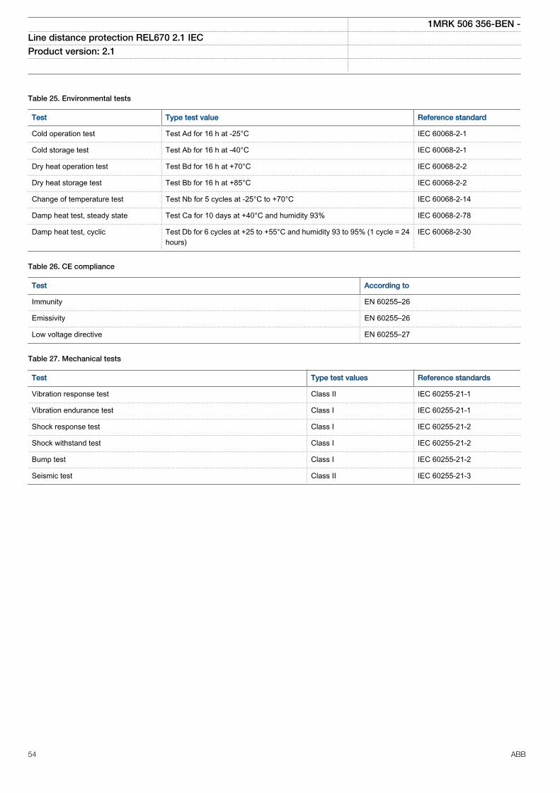
Table 25. Environmental tests
Test Type test value Reference standard
Cold operation test Test Ad for 16 h at -25°C IEC 60068-2-1
Cold storage test Test Ab for 16 h at -40°C IEC 60068-2-1
Dry heat operation test Test Bd for 16 h at +70°C IEC 60068-2-2
Dry heat storage test Test Bb for 16 h at +85°C IEC 60068-2-2
Change of temperature test Test Nb for 5 cycles at -25°C to +70°C IEC 60068-2-14
Damp heat test, steady state Test Ca for 10 days at +40°C and humidity 93% IEC 60068-2-78
Damp heat test, cyclic Test Db for 6 cycles at +25 to +55°C and humidity 93 to 95% (1 cycle = 24hours)
IEC 60068-2-30
Table 26. CE compliance
Test According to
Immunity EN 60255–26
Emissivity EN 60255–26
Low voltage directive EN 60255–27
Table 27. Mechanical tests
Test Type test values Reference standards
Vibration response test Class II IEC 60255-21-1
Vibration endurance test Class I IEC 60255-21-1
Shock response test Class I IEC 60255-21-2
Shock withstand test Class I IEC 60255-21-2
Bump test Class I IEC 60255-21-2
Seismic test Class II IEC 60255-21-3
1MRK 506 356-BEN -Line distance protection REL670 2.1 IEC Product version: 2.1
54 ABB
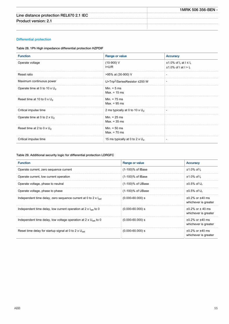
Differential protection
Table 28. 1Ph High impedance differential protection HZPDIF
Function Range or value Accuracy
Operate voltage (10-900) VI=U/R
±1.0% of Ir at I ≤ Ir±1.0% of I at I > Ir
Reset ratio >95% at (30-900) V -
Maximum continuous power U>Trip2/SeriesResistor ≤200 W -
Operate time at 0 to 10 x Ud Min. = 5 msMax. = 15 ms
Reset time at 10 to 0 x Ud Min. = 75 msMax. = 95 ms
Critical impulse time 2 ms typically at 0 to 10 x Ud -
Operate time at 0 to 2 x Ud Min. = 25 msMax. = 35 ms
Reset time at 2 to 0 x Ud Min. = 50 msMax. = 70 ms
Critical impulse time 15 ms typically at 0 to 2 x Ud -
Table 29. Additional security logic for differential protection LDRGFC
Function Range or value Accuracy
Operate current, zero sequence current (1-100)% of lBase ±1.0% of Ir
Operate current, low current operation (1-100)% of lBase ±1.0% of Ir
Operate voltage, phase to neutral (1-100)% of UBase ±0.5% of Ur
Operate voltage, phase to phase (1-100)% of UBase ±0.5% of Ur
Independent time delay, zero sequence current at 0 to 2 x Iset (0.000-60.000) s ±0.2% or ±40 mswhichever is greater
Independent time delay, low current operation at 2 x Iset to 0 (0.000-60.000) s ±0.2% or ± 40 mswhichever is greater
Independent time delay, low voltage operation at 2 x Uset to 0 (0.000-60.000) s ±0.2% or ±40 mswhichever is greater
Reset time delay for startup signal at 0 to 2 x Uset (0.000-60.000) s ±0.2% or ±40 mswhichever is greater
1MRK 506 356-BEN -Line distance protection REL670 2.1 IEC Product version: 2.1
ABB 55
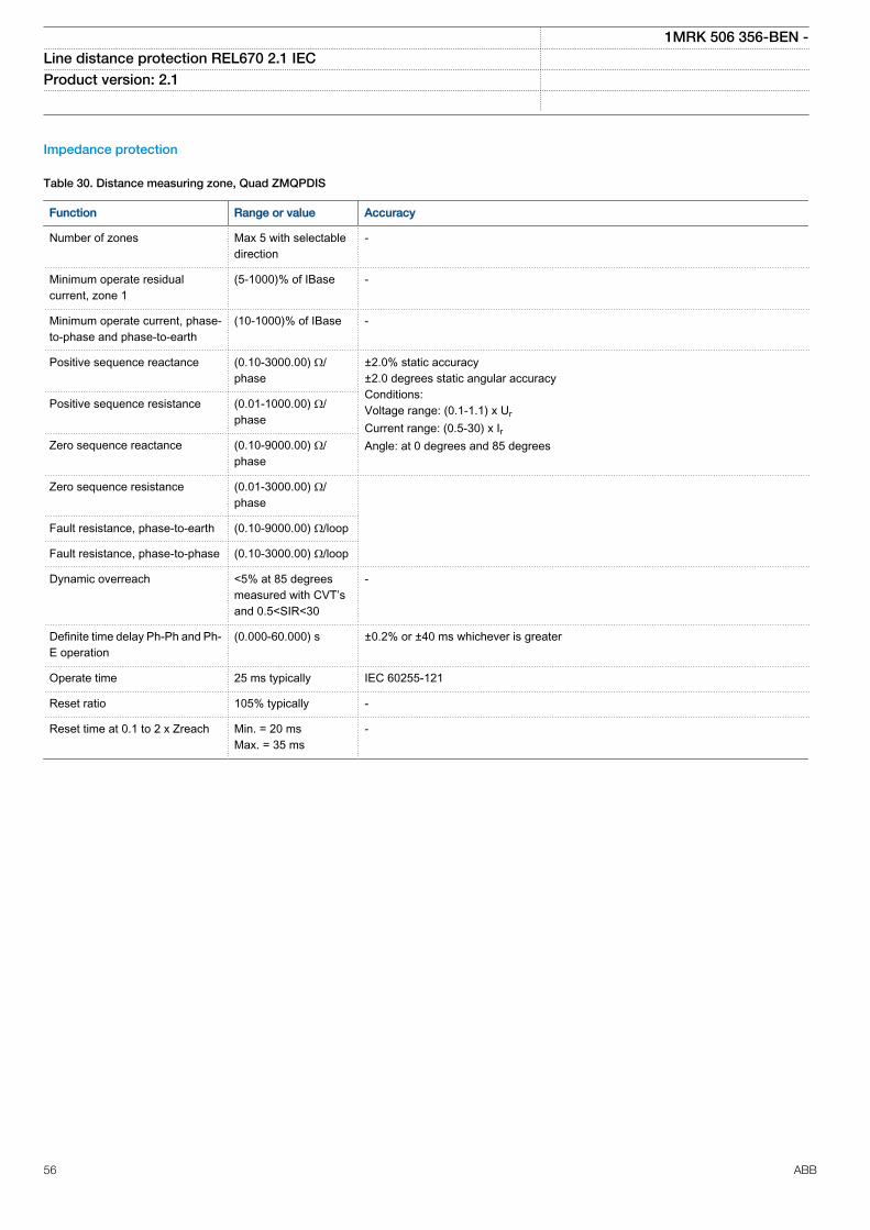
Impedance protection
Table 30. Distance measuring zone, Quad ZMQPDIS
Function Range or value Accuracy
Number of zones Max 5 with selectabledirection
-
Minimum operate residualcurrent, zone 1
(5-1000)% of IBase -
Minimum operate current, phase-to-phase and phase-to-earth
(10-1000)% of IBase -
Positive sequence reactance (0.10-3000.00) Ω/phase
±2.0% static accuracy±2.0 degrees static angular accuracyConditions:Voltage range: (0.1-1.1) x UrCurrent range: (0.5-30) x IrAngle: at 0 degrees and 85 degrees
Positive sequence resistance (0.01-1000.00) Ω/phase
Zero sequence reactance (0.10-9000.00) Ω/phase
Zero sequence resistance (0.01-3000.00) Ω/phase
Fault resistance, phase-to-earth (0.10-9000.00) Ω/loop
Fault resistance, phase-to-phase (0.10-3000.00) Ω/loop
Dynamic overreach <5% at 85 degreesmeasured with CVT’sand 0.5<SIR<30
-
Definite time delay Ph-Ph and Ph-E operation
(0.000-60.000) s ±0.2% or ±40 ms whichever is greater
Operate time 25 ms typically IEC 60255-121
Reset ratio 105% typically -
Reset time at 0.1 to 2 x Zreach Min. = 20 msMax. = 35 ms
-
1MRK 506 356-BEN -Line distance protection REL670 2.1 IEC Product version: 2.1
56 ABB
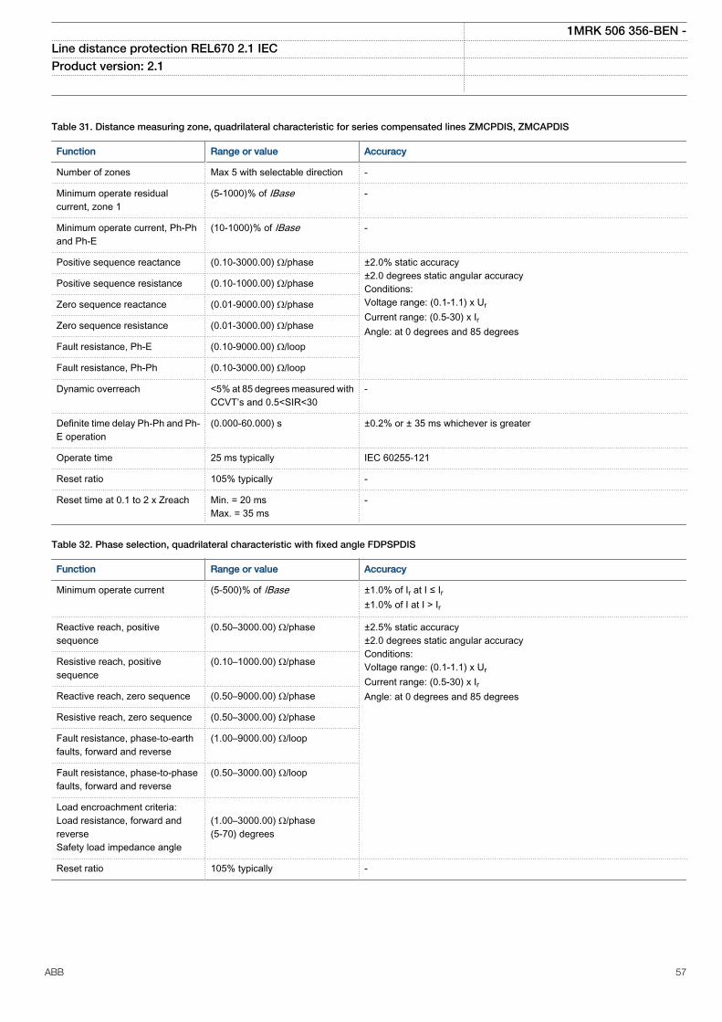
Table 31. Distance measuring zone, quadrilateral characteristic for series compensated lines ZMCPDIS, ZMCAPDIS
Function Range or value Accuracy
Number of zones Max 5 with selectable direction -
Minimum operate residualcurrent, zone 1
(5-1000)% of IBase -
Minimum operate current, Ph-Phand Ph-E
(10-1000)% of IBase -
Positive sequence reactance (0.10-3000.00) Ω/phase ±2.0% static accuracy±2.0 degrees static angular accuracyConditions:Voltage range: (0.1-1.1) x UrCurrent range: (0.5-30) x IrAngle: at 0 degrees and 85 degrees
Positive sequence resistance (0.10-1000.00) Ω/phase
Zero sequence reactance (0.01-9000.00) Ω/phase
Zero sequence resistance (0.01-3000.00) Ω/phase
Fault resistance, Ph-E (0.10-9000.00) Ω/loop
Fault resistance, Ph-Ph (0.10-3000.00) Ω/loop
Dynamic overreach <5% at 85 degrees measured withCCVT’s and 0.5<SIR<30
-
Definite time delay Ph-Ph and Ph-E operation
(0.000-60.000) s ±0.2% or ± 35 ms whichever is greater
Operate time 25 ms typically IEC 60255-121
Reset ratio 105% typically -
Reset time at 0.1 to 2 x Zreach Min. = 20 msMax. = 35 ms
-
Table 32. Phase selection, quadrilateral characteristic with fixed angle FDPSPDIS
Function Range or value Accuracy
Minimum operate current (5-500)% of IBase ±1.0% of Ir at I ≤ Ir±1.0% of I at I > Ir
Reactive reach, positivesequence
(0.50–3000.00) Ω/phase ±2.5% static accuracy±2.0 degrees static angular accuracyConditions:Voltage range: (0.1-1.1) x UrCurrent range: (0.5-30) x IrAngle: at 0 degrees and 85 degrees
Resistive reach, positivesequence
(0.10–1000.00) Ω/phase
Reactive reach, zero sequence (0.50–9000.00) Ω/phase
Resistive reach, zero sequence (0.50–3000.00) Ω/phase
Fault resistance, phase-to-earthfaults, forward and reverse
(1.00–9000.00) Ω/loop
Fault resistance, phase-to-phasefaults, forward and reverse
(0.50–3000.00) Ω/loop
Load encroachment criteria:Load resistance, forward andreverseSafety load impedance angle
(1.00–3000.00) Ω/phase(5-70) degrees
Reset ratio 105% typically -
1MRK 506 356-BEN -Line distance protection REL670 2.1 IEC Product version: 2.1
ABB 57
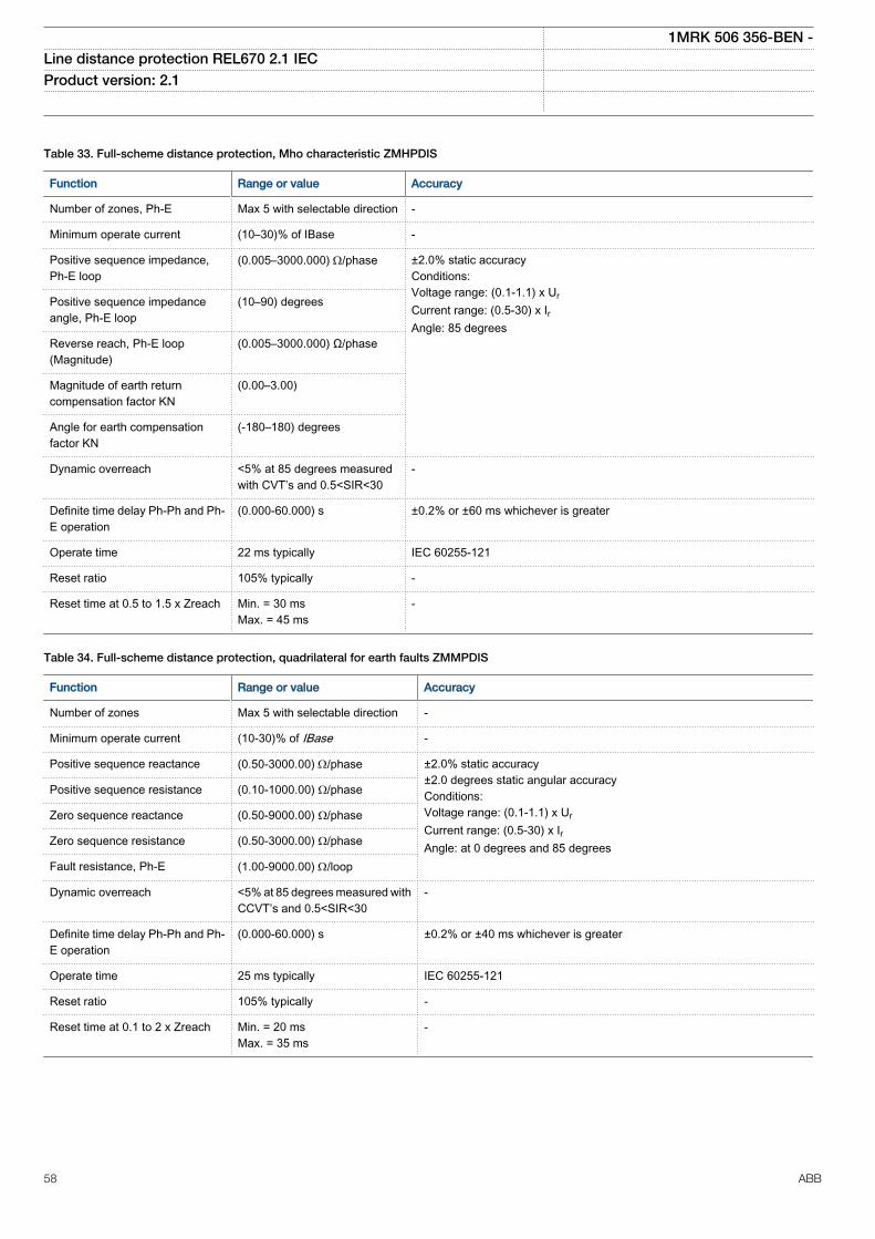
Table 33. Full-scheme distance protection, Mho characteristic ZMHPDIS
Function Range or value Accuracy
Number of zones, Ph-E Max 5 with selectable direction -
Minimum operate current (10–30)% of IBase -
Positive sequence impedance,Ph-E loop
(0.005–3000.000) W/phase ±2.0% static accuracyConditions:Voltage range: (0.1-1.1) x UrCurrent range: (0.5-30) x IrAngle: 85 degrees
Positive sequence impedanceangle, Ph-E loop
(10–90) degrees
Reverse reach, Ph-E loop(Magnitude)
(0.005–3000.000) Ω/phase
Magnitude of earth returncompensation factor KN
(0.00–3.00)
Angle for earth compensationfactor KN
(-180–180) degrees
Dynamic overreach <5% at 85 degrees measuredwith CVT’s and 0.5<SIR<30
-
Definite time delay Ph-Ph and Ph-E operation
(0.000-60.000) s ±0.2% or ±60 ms whichever is greater
Operate time 22 ms typically IEC 60255-121
Reset ratio 105% typically -
Reset time at 0.5 to 1.5 x Zreach Min. = 30 msMax. = 45 ms
-
Table 34. Full-scheme distance protection, quadrilateral for earth faults ZMMPDIS
Function Range or value Accuracy
Number of zones Max 5 with selectable direction -
Minimum operate current (10-30)% of IBase -
Positive sequence reactance (0.50-3000.00) W/phase ±2.0% static accuracy±2.0 degrees static angular accuracyConditions:Voltage range: (0.1-1.1) x UrCurrent range: (0.5-30) x IrAngle: at 0 degrees and 85 degrees
Positive sequence resistance (0.10-1000.00) Ω/phase
Zero sequence reactance (0.50-9000.00) Ω/phase
Zero sequence resistance (0.50-3000.00) Ω/phase
Fault resistance, Ph-E (1.00-9000.00) W/loop
Dynamic overreach <5% at 85 degrees measured withCCVT’s and 0.5<SIR<30
-
Definite time delay Ph-Ph and Ph-E operation
(0.000-60.000) s ±0.2% or ±40 ms whichever is greater
Operate time 25 ms typically IEC 60255-121
Reset ratio 105% typically -
Reset time at 0.1 to 2 x Zreach Min. = 20 msMax. = 35 ms
-
1MRK 506 356-BEN -Line distance protection REL670 2.1 IEC Product version: 2.1
58 ABB
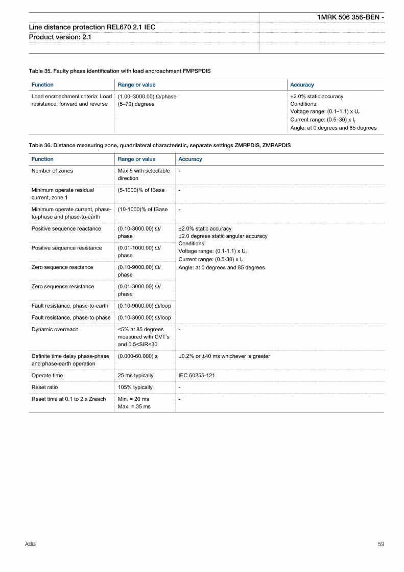
Table 35. Faulty phase identification with load encroachment FMPSPDIS
Function Range or value Accuracy
Load encroachment criteria: Loadresistance, forward and reverse
(1.00–3000.00) W/phase(5–70) degrees
±2.0% static accuracyConditions:Voltage range: (0.1–1.1) x UrCurrent range: (0.5–30) x IrAngle: at 0 degrees and 85 degrees
Table 36. Distance measuring zone, quadrilateral characteristic, separate settings ZMRPDIS, ZMRAPDIS
Function Range or value Accuracy
Number of zones Max 5 with selectabledirection
-
Minimum operate residualcurrent, zone 1
(5-1000)% of IBase -
Minimum operate current, phase-to-phase and phase-to-earth
(10-1000)% of IBase -
Positive sequence reactance (0.10-3000.00) Ω/phase
±2.0% static accuracy±2.0 degrees static angular accuracyConditions:Voltage range: (0.1-1.1) x UrCurrent range: (0.5-30) x IrAngle: at 0 degrees and 85 degrees
Positive sequence resistance (0.01-1000.00) Ω/phase
Zero sequence reactance (0.10-9000.00) Ω/phase
Zero sequence resistance (0.01-3000.00) Ω/phase
Fault resistance, phase-to-earth (0.10-9000.00) Ω/loop
Fault resistance, phase-to-phase (0.10-3000.00) Ω/loop
Dynamic overreach <5% at 85 degreesmeasured with CVT’sand 0.5<SIR<30
-
Definite time delay phase-phaseand phase-earth operation
(0.000-60.000) s ±0.2% or ±40 ms whichever is greater
Operate time 25 ms typically IEC 60255-121
Reset ratio 105% typically -
Reset time at 0.1 to 2 x Zreach Min. = 20 msMax. = 35 ms
-
1MRK 506 356-BEN -Line distance protection REL670 2.1 IEC Product version: 2.1
ABB 59
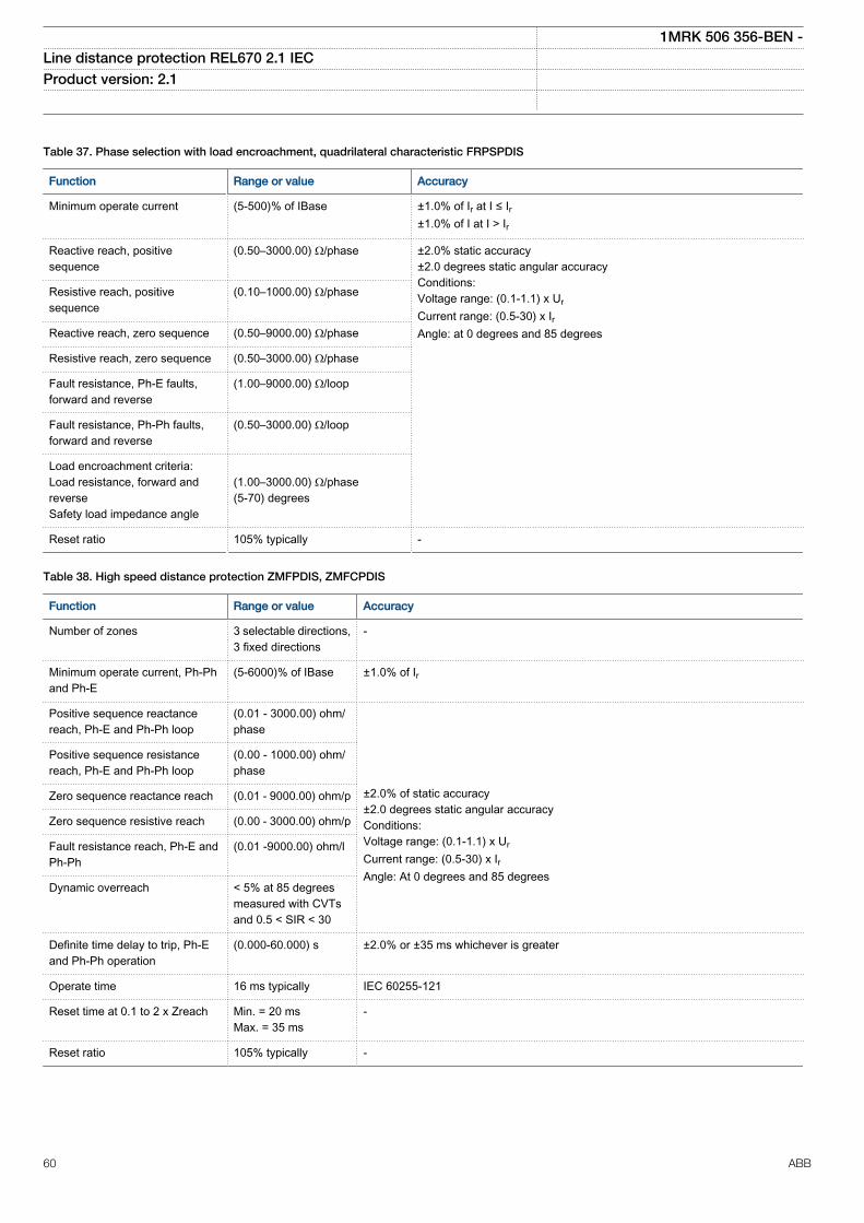
Table 37. Phase selection with load encroachment, quadrilateral characteristic FRPSPDIS
Function Range or value Accuracy
Minimum operate current (5-500)% of IBase ±1.0% of Ir at I ≤ Ir±1.0% of I at I > Ir
Reactive reach, positivesequence
(0.50–3000.00) Ω/phase ±2.0% static accuracy±2.0 degrees static angular accuracyConditions:Voltage range: (0.1-1.1) x UrCurrent range: (0.5-30) x IrAngle: at 0 degrees and 85 degrees
Resistive reach, positivesequence
(0.10–1000.00) Ω/phase
Reactive reach, zero sequence (0.50–9000.00) Ω/phase
Resistive reach, zero sequence (0.50–3000.00) Ω/phase
Fault resistance, Ph-E faults,forward and reverse
(1.00–9000.00) Ω/loop
Fault resistance, Ph-Ph faults,forward and reverse
(0.50–3000.00) Ω/loop
Load encroachment criteria:Load resistance, forward andreverseSafety load impedance angle
(1.00–3000.00) Ω/phase(5-70) degrees
Reset ratio 105% typically -
Table 38. High speed distance protection ZMFPDIS, ZMFCPDIS
Function Range or value Accuracy
Number of zones 3 selectable directions,3 fixed directions
-
Minimum operate current, Ph-Phand Ph-E
(5-6000)% of IBase ±1.0% of Ir
Positive sequence reactancereach, Ph-E and Ph-Ph loop
(0.01 - 3000.00) ohm/phase
±2.0% of static accuracy±2.0 degrees static angular accuracyConditions:Voltage range: (0.1-1.1) x UrCurrent range: (0.5-30) x IrAngle: At 0 degrees and 85 degrees
Positive sequence resistancereach, Ph-E and Ph-Ph loop
(0.00 - 1000.00) ohm/phase
Zero sequence reactance reach (0.01 - 9000.00) ohm/p
Zero sequence resistive reach (0.00 - 3000.00) ohm/p
Fault resistance reach, Ph-E andPh-Ph
(0.01 -9000.00) ohm/l
Dynamic overreach < 5% at 85 degreesmeasured with CVTsand 0.5 < SIR < 30
Definite time delay to trip, Ph-Eand Ph-Ph operation
(0.000-60.000) s ±2.0% or ±35 ms whichever is greater
Operate time 16 ms typically IEC 60255-121
Reset time at 0.1 to 2 x Zreach Min. = 20 msMax. = 35 ms
-
Reset ratio 105% typically -
1MRK 506 356-BEN -Line distance protection REL670 2.1 IEC Product version: 2.1
60 ABB
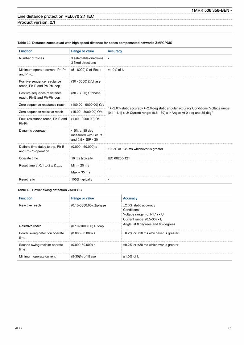
Table 39. Distance zones quad with high speed distance for series compensated networks ZMFCPDIS
Function Range or value Accuracy
Number of zones 3 selectable directions,3 fixed directions
-
Minimum operate current, Ph-Phand Ph-E
(5 - 6000)% of IBase ±1.0% of In
Positive sequence reactancereach, Ph-E and Ph-Ph loop
(30 - 3000) Ω/phase
" +- 2.0% static accuracy +- 2.0 deg static angular accuracy Conditions: Voltage range:(0.1 - 1.1) x Ur Current range: (0.5 - 30) x Ir Angle: At 0 deg and 85 deg"
Positive sequence resistancereach, Ph-E and Ph-Ph loop
(30 - 3000) Ω/phase
Zero sequence reactance reach (100.00 - 9000.00) Ω/p
Zero sequence resistive reach (15.00 - 3000.00) Ω/p
Fault resistance reach, Ph-E andPh-Ph
(1.00 - 9000.00) Ω/l
Dynamic overreach < 5% at 85 degmeasured with CVT'sand 0.5 < SIR <30
Definite time delay to trip, Ph-Eand Ph-Ph operation
(0.000 - 60.000) s ±0.2% or ±35 ms whichever is greater
Operate time 16 ms typically IEC 60255-121
Reset time at 0.1 to 2 x Zreach Min = 20 ms-
Max = 35 ms
Reset ratio 105% typically -
Table 40. Power swing detection ZMRPSB
Function Range or value Accuracy
Reactive reach (0.10-3000.00) W/phase
±2.0% static accuracyConditions:Voltage range: (0.1-1.1) x UrCurrent range: (0.5-30) x IrAngle: at 0 degrees and 85 degreesResistive reach (0.10–1000.00) W/loop
Power swing detection operatetime
(0.000-60.000) s ±0.2% or ±10 ms whichever is greater
Second swing reclaim operatetime
(0.000-60.000) s ±0.2% or ±20 ms whichever is greater
Minimum operate current (5-30)% of IBase ±1.0% of Ir
1MRK 506 356-BEN -Line distance protection REL670 2.1 IEC Product version: 2.1
ABB 61
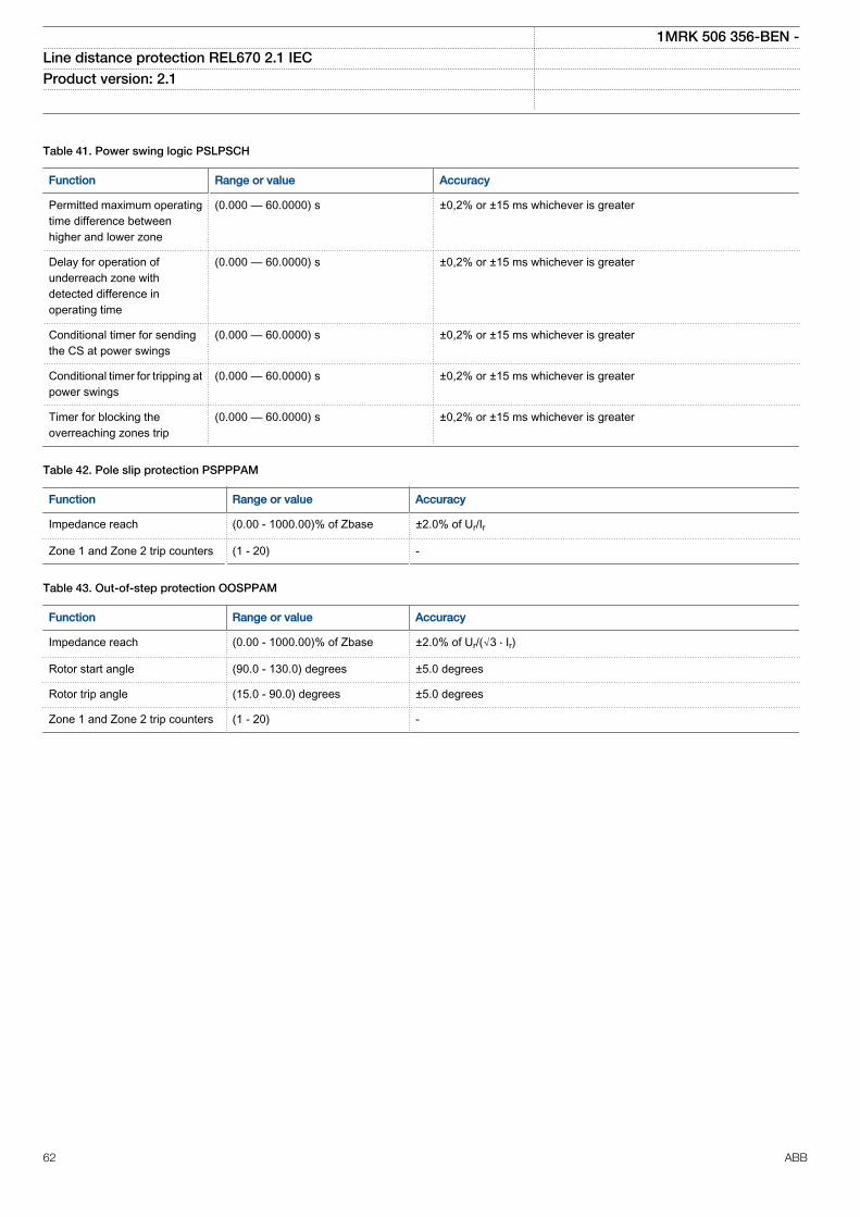
Table 41. Power swing logic PSLPSCH
Function Range or value Accuracy
Permitted maximum operatingtime difference betweenhigher and lower zone
(0.000 — 60.0000) s ±0,2% or ±15 ms whichever is greater
Delay for operation ofunderreach zone withdetected difference inoperating time
(0.000 — 60.0000) s ±0,2% or ±15 ms whichever is greater
Conditional timer for sendingthe CS at power swings
(0.000 — 60.0000) s ±0,2% or ±15 ms whichever is greater
Conditional timer for tripping atpower swings
(0.000 — 60.0000) s ±0,2% or ±15 ms whichever is greater
Timer for blocking theoverreaching zones trip
(0.000 — 60.0000) s ±0,2% or ±15 ms whichever is greater
Table 42. Pole slip protection PSPPPAM
Function Range or value Accuracy
Impedance reach (0.00 - 1000.00)% of Zbase ±2.0% of Ur/Ir
Zone 1 and Zone 2 trip counters (1 - 20) -
Table 43. Out-of-step protection OOSPPAM
Function Range or value Accuracy
Impedance reach (0.00 - 1000.00)% of Zbase ±2.0% of Ur/(√3 ⋅ Ir)
Rotor start angle (90.0 - 130.0) degrees ±5.0 degrees
Rotor trip angle (15.0 - 90.0) degrees ±5.0 degrees
Zone 1 and Zone 2 trip counters (1 - 20) -
1MRK 506 356-BEN -Line distance protection REL670 2.1 IEC Product version: 2.1
62 ABB
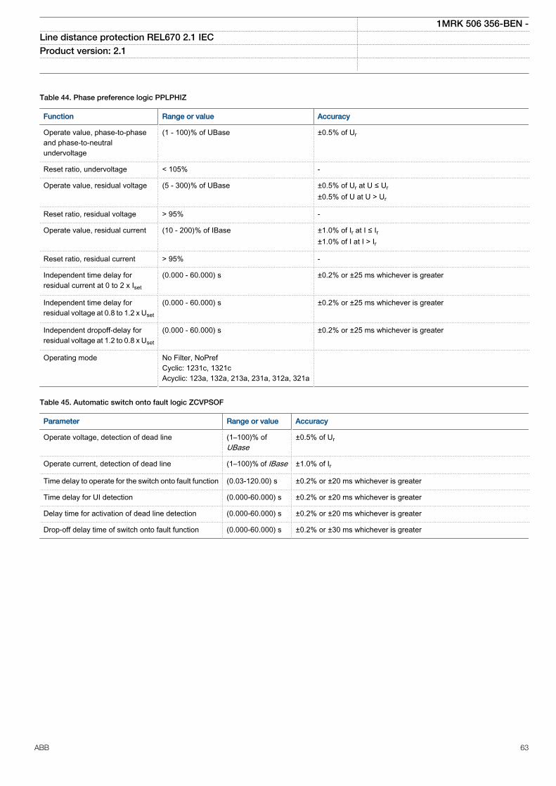
Table 44. Phase preference logic PPLPHIZ
Function Range or value Accuracy
Operate value, phase-to-phaseand phase-to-neutralundervoltage
(1 - 100)% of UBase ±0.5% of Ur
Reset ratio, undervoltage < 105% -
Operate value, residual voltage (5 - 300)% of UBase ±0.5% of Ur at U ≤ Ur±0.5% of U at U > Ur
Reset ratio, residual voltage > 95% -
Operate value, residual current (10 - 200)% of IBase ±1.0% of Ir at I ≤ Ir±1.0% of I at I > Ir
Reset ratio, residual current > 95% -
Independent time delay forresidual current at 0 to 2 x Iset
(0.000 - 60.000) s ±0.2% or ±25 ms whichever is greater
Independent time delay forresidual voltage at 0.8 to 1.2 x Uset
(0.000 - 60.000) s ±0.2% or ±25 ms whichever is greater
Independent dropoff-delay forresidual voltage at 1.2 to 0.8 x Uset
(0.000 - 60.000) s ±0.2% or ±25 ms whichever is greater
Operating mode No Filter, NoPrefCyclic: 1231c, 1321cAcyclic: 123a, 132a, 213a, 231a, 312a, 321a
Table 45. Automatic switch onto fault logic ZCVPSOF
Parameter Range or value Accuracy
Operate voltage, detection of dead line (1–100)% ofUBase
±0.5% of Ur
Operate current, detection of dead line (1–100)% of IBase ±1.0% of Ir
Time delay to operate for the switch onto fault function (0.03-120.00) s ±0.2% or ±20 ms whichever is greater
Time delay for UI detection (0.000-60.000) s ±0.2% or ±20 ms whichever is greater
Delay time for activation of dead line detection (0.000-60.000) s ±0.2% or ±20 ms whichever is greater
Drop-off delay time of switch onto fault function (0.000-60.000) s ±0.2% or ±30 ms whichever is greater
1MRK 506 356-BEN -Line distance protection REL670 2.1 IEC Product version: 2.1
ABB 63
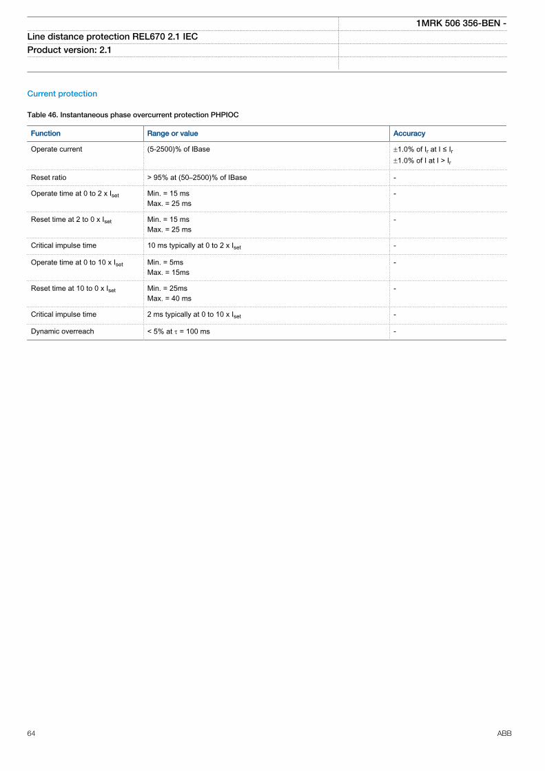
Current protection
Table 46. Instantaneous phase overcurrent protection PHPIOC
Function Range or value Accuracy
Operate current (5-2500)% of lBase ±1.0% of Ir at I ≤ Ir±1.0% of I at I > Ir
Reset ratio > 95% at (50–2500)% of IBase -
Operate time at 0 to 2 x Iset Min. = 15 msMax. = 25 ms
-
Reset time at 2 to 0 x Iset Min. = 15 msMax. = 25 ms
-
Critical impulse time 10 ms typically at 0 to 2 x Iset -
Operate time at 0 to 10 x Iset Min. = 5msMax. = 15ms
-
Reset time at 10 to 0 x Iset Min. = 25msMax. = 40 ms
-
Critical impulse time 2 ms typically at 0 to 10 x Iset -
Dynamic overreach < 5% at t = 100 ms -
1MRK 506 356-BEN -Line distance protection REL670 2.1 IEC Product version: 2.1
64 ABB
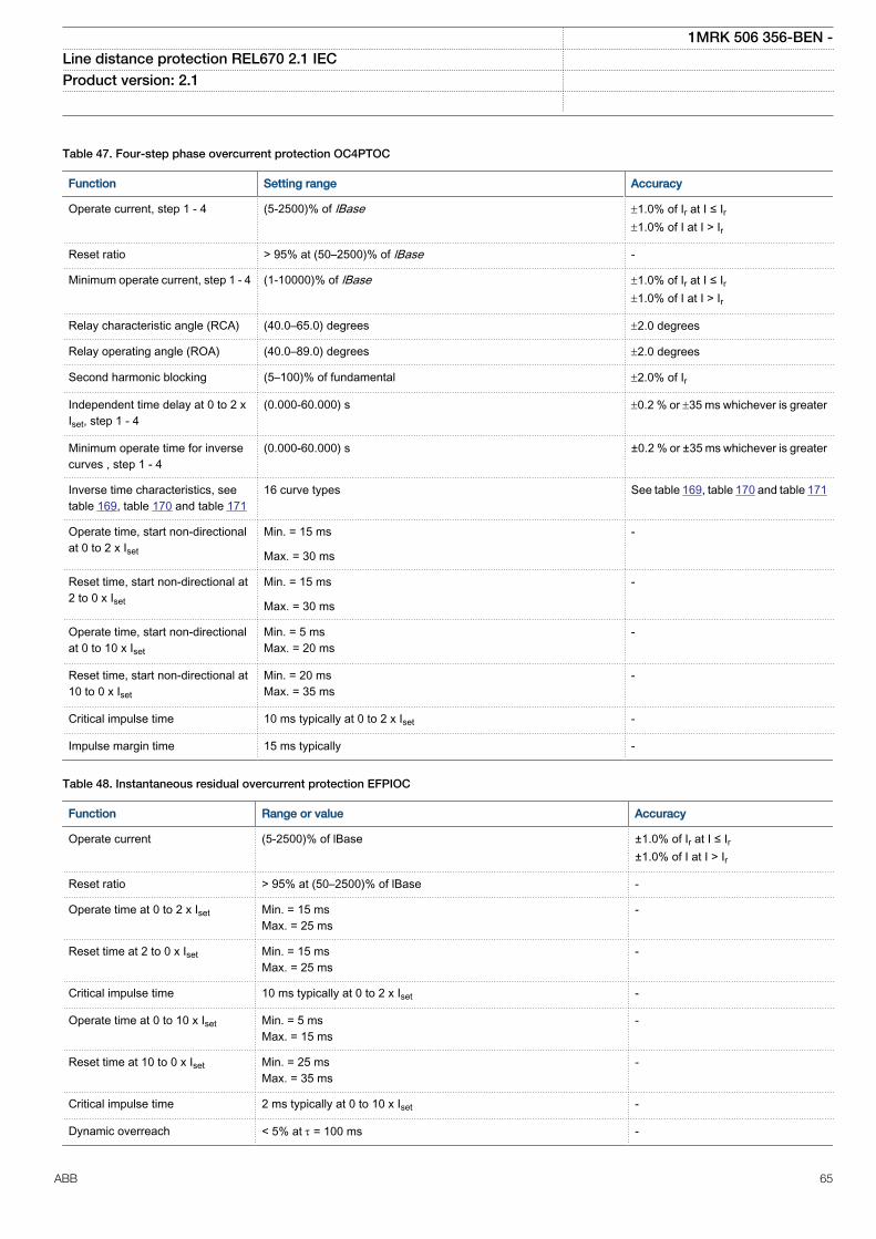
Table 47. Four-step phase overcurrent protection OC4PTOC
Function Setting range Accuracy
Operate current, step 1 - 4 (5-2500)% of lBase ±1.0% of Ir at I ≤ Ir±1.0% of I at I > Ir
Reset ratio > 95% at (50–2500)% of lBase -
Minimum operate current, step 1 - 4 (1-10000)% of lBase ±1.0% of Ir at I ≤ Ir±1.0% of I at I > Ir
Relay characteristic angle (RCA) (40.0–65.0) degrees ±2.0 degrees
Relay operating angle (ROA) (40.0–89.0) degrees ±2.0 degrees
Second harmonic blocking (5–100)% of fundamental ±2.0% of Ir
Independent time delay at 0 to 2 xIset, step 1 - 4
(0.000-60.000) s ±0.2 % or ±35 ms whichever is greater
Minimum operate time for inversecurves , step 1 - 4
(0.000-60.000) s ±0.2 % or ±35 ms whichever is greater
Inverse time characteristics, seetable 169, table 170 and table 171
16 curve types See table 169, table 170 and table 171
Operate time, start non-directionalat 0 to 2 x Iset
Min. = 15 ms -
Max. = 30 ms
Reset time, start non-directional at2 to 0 x Iset
Min. = 15 ms -
Max. = 30 ms
Operate time, start non-directionalat 0 to 10 x Iset
Min. = 5 msMax. = 20 ms
-
Reset time, start non-directional at10 to 0 x Iset
Min. = 20 msMax. = 35 ms
-
Critical impulse time 10 ms typically at 0 to 2 x Iset -
Impulse margin time 15 ms typically -
Table 48. Instantaneous residual overcurrent protection EFPIOC
Function Range or value Accuracy
Operate current (5-2500)% of lBase ±1.0% of Ir at I ≤ Ir±1.0% of I at I > Ir
Reset ratio > 95% at (50–2500)% of lBase -
Operate time at 0 to 2 x Iset Min. = 15 msMax. = 25 ms
-
Reset time at 2 to 0 x Iset Min. = 15 msMax. = 25 ms
-
Critical impulse time 10 ms typically at 0 to 2 x Iset -
Operate time at 0 to 10 x Iset Min. = 5 msMax. = 15 ms
-
Reset time at 10 to 0 x Iset Min. = 25 msMax. = 35 ms
-
Critical impulse time 2 ms typically at 0 to 10 x Iset -
Dynamic overreach < 5% at t = 100 ms -
1MRK 506 356-BEN -Line distance protection REL670 2.1 IEC Product version: 2.1
ABB 65
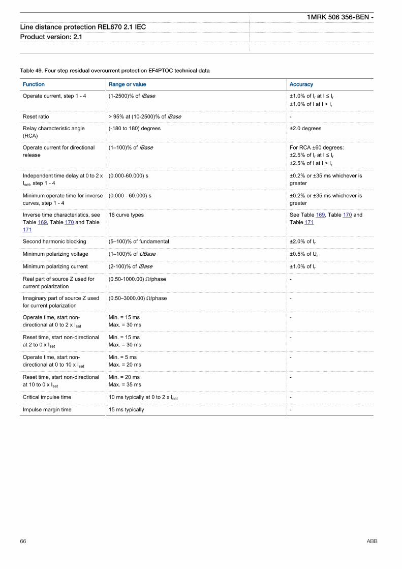
Table 49. Four step residual overcurrent protection EF4PTOC technical data
Function Range or value Accuracy
Operate current, step 1 - 4 (1-2500)% of lBase ±1.0% of Ir at I ≤ Ir±1.0% of I at I > Ir
Reset ratio > 95% at (10-2500)% of lBase -
Relay characteristic angle(RCA)
(-180 to 180) degrees ±2.0 degrees
Operate current for directionalrelease
(1–100)% of lBase For RCA ±60 degrees:±2.5% of Ir at I ≤ Ir±2.5% of I at I > Ir
Independent time delay at 0 to 2 xIset, step 1 - 4
(0.000-60.000) s ±0.2% or ±35 ms whichever isgreater
Minimum operate time for inversecurves, step 1 - 4
(0.000 - 60.000) s ±0.2% or ±35 ms whichever isgreater
Inverse time characteristics, seeTable 169, Table 170 and Table171
16 curve types See Table 169, Table 170 andTable 171
Second harmonic blocking (5–100)% of fundamental ±2.0% of Ir
Minimum polarizing voltage (1–100)% of UBase ±0.5% of Ur
Minimum polarizing current (2-100)% of IBase ±1.0% of Ir
Real part of source Z used forcurrent polarization
(0.50-1000.00) W/phase -
Imaginary part of source Z usedfor current polarization
(0.50–3000.00) W/phase -
Operate time, start non-directional at 0 to 2 x Iset
Min. = 15 msMax. = 30 ms
-
Reset time, start non-directionalat 2 to 0 x Iset
Min. = 15 msMax. = 30 ms
-
Operate time, start non-directional at 0 to 10 x Iset
Min. = 5 msMax. = 20 ms
-
Reset time, start non-directionalat 10 to 0 x Iset
Min. = 20 msMax. = 35 ms
-
Critical impulse time 10 ms typically at 0 to 2 x Iset -
Impulse margin time 15 ms typically -
1MRK 506 356-BEN -Line distance protection REL670 2.1 IEC Product version: 2.1
66 ABB
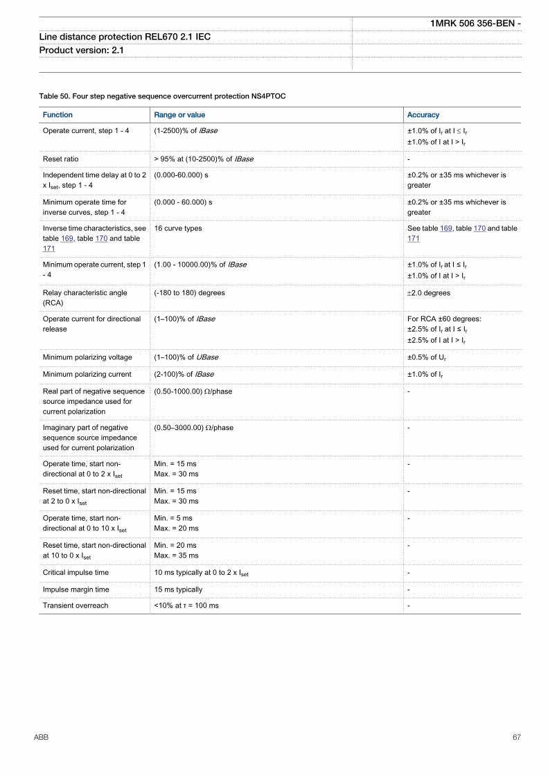
Table 50. Four step negative sequence overcurrent protection NS4PTOC
Function Range or value Accuracy
Operate current, step 1 - 4 (1-2500)% of lBase ±1.0% of Ir at I £ Ir±1.0% of I at I > Ir
Reset ratio > 95% at (10-2500)% of IBase -
Independent time delay at 0 to 2x Iset, step 1 - 4
(0.000-60.000) s ±0.2% or ±35 ms whichever isgreater
Minimum operate time forinverse curves, step 1 - 4
(0.000 - 60.000) s ±0.2% or ±35 ms whichever isgreater
Inverse time characteristics, seetable 169, table 170 and table171
16 curve types See table 169, table 170 and table171
Minimum operate current, step 1- 4
(1.00 - 10000.00)% of IBase ±1.0% of Ir at I ≤ Ir±1.0% of I at I > Ir
Relay characteristic angle(RCA)
(-180 to 180) degrees ±2.0 degrees
Operate current for directionalrelease
(1–100)% of IBase For RCA ±60 degrees:±2.5% of Ir at I ≤ Ir±2.5% of I at I > Ir
Minimum polarizing voltage (1–100)% of UBase ±0.5% of Ur
Minimum polarizing current (2-100)% of IBase ±1.0% of Ir
Real part of negative sequencesource impedance used forcurrent polarization
(0.50-1000.00) W/phase -
Imaginary part of negativesequence source impedanceused for current polarization
(0.50–3000.00) W/phase -
Operate time, start non-directional at 0 to 2 x Iset
Min. = 15 msMax. = 30 ms
-
Reset time, start non-directionalat 2 to 0 x Iset
Min. = 15 msMax. = 30 ms
-
Operate time, start non-directional at 0 to 10 x Iset
Min. = 5 msMax. = 20 ms
-
Reset time, start non-directionalat 10 to 0 x Iset
Min. = 20 msMax. = 35 ms
-
Critical impulse time 10 ms typically at 0 to 2 x Iset -
Impulse margin time 15 ms typically -
Transient overreach <10% at τ = 100 ms -
1MRK 506 356-BEN -Line distance protection REL670 2.1 IEC Product version: 2.1
ABB 67
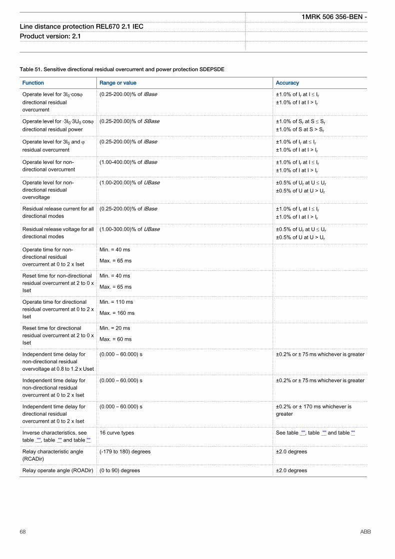
Table 51. Sensitive directional residual overcurrent and power protection SDEPSDE
Function Range or value Accuracy
Operate level for 3I0·cosjdirectional residualovercurrent
(0.25-200.00)% of lBase ±1.0% of Ir at I £ Ir±1.0% of I at I > Ir
Operate level for ·3I0·3U0 cosjdirectional residual power
(0.25-200.00)% of SBase ±1.0% of Sr at S £ Sr±1.0% of S at S > Sr
Operate level for 3I0 and jresidual overcurrent
(0.25-200.00)% of lBase ±1.0% of Ir at £ Ir±1.0% of I at I > Ir
Operate level for non-directional overcurrent
(1.00-400.00)% of lBase ±1.0% of Ir at I £ Ir±1.0% of I at I > Ir
Operate level for non-directional residualovervoltage
(1.00-200.00)% of UBase ±0.5% of Ur at U £ Ur±0.5% of U at U > Ur
Residual release current for alldirectional modes
(0.25-200.00)% of lBase ±1.0% of Ir at I £ Ir±1.0% of I at I > Ir
Residual release voltage for alldirectional modes
(1.00-300.00)% of UBase ±0.5% of Ur at U £ Ur±0.5% of U at U > Ur
Operate time for non-directional residualovercurrent at 0 to 2 x Iset
Min. = 40 ms
Max. = 65 ms
Reset time for non-directionalresidual overcurrent at 2 to 0 xIset
Min. = 40 ms
Max. = 65 ms
Operate time for directionalresidual overcurrent at 0 to 2 xIset
Min. = 110 ms
Max. = 160 ms
Reset time for directionalresidual overcurrent at 2 to 0 xIset
Min. = 20 ms
Max. = 60 ms
Independent time delay fornon-directional residualovervoltage at 0.8 to 1.2 x Uset
(0.000 – 60.000) s ±0.2% or ± 75 ms whichever is greater
Independent time delay fornon-directional residualovercurrent at 0 to 2 x Iset
(0.000 – 60.000) s ±0.2% or ± 75 ms whichever is greater
Independent time delay fordirectional residualovercurrent at 0 to 2 x Iset
(0.000 – 60.000) s ±0.2% or ± 170 ms whichever isgreater
Inverse characteristics, seetable "", table "" and table ""
16 curve types See table "", table "" and table ""
Relay characteristic angle(RCADir)
(-179 to 180) degrees ±2.0 degrees
Relay operate angle (ROADir) (0 to 90) degrees ±2.0 degrees
1MRK 506 356-BEN -Line distance protection REL670 2.1 IEC Product version: 2.1
68 ABB
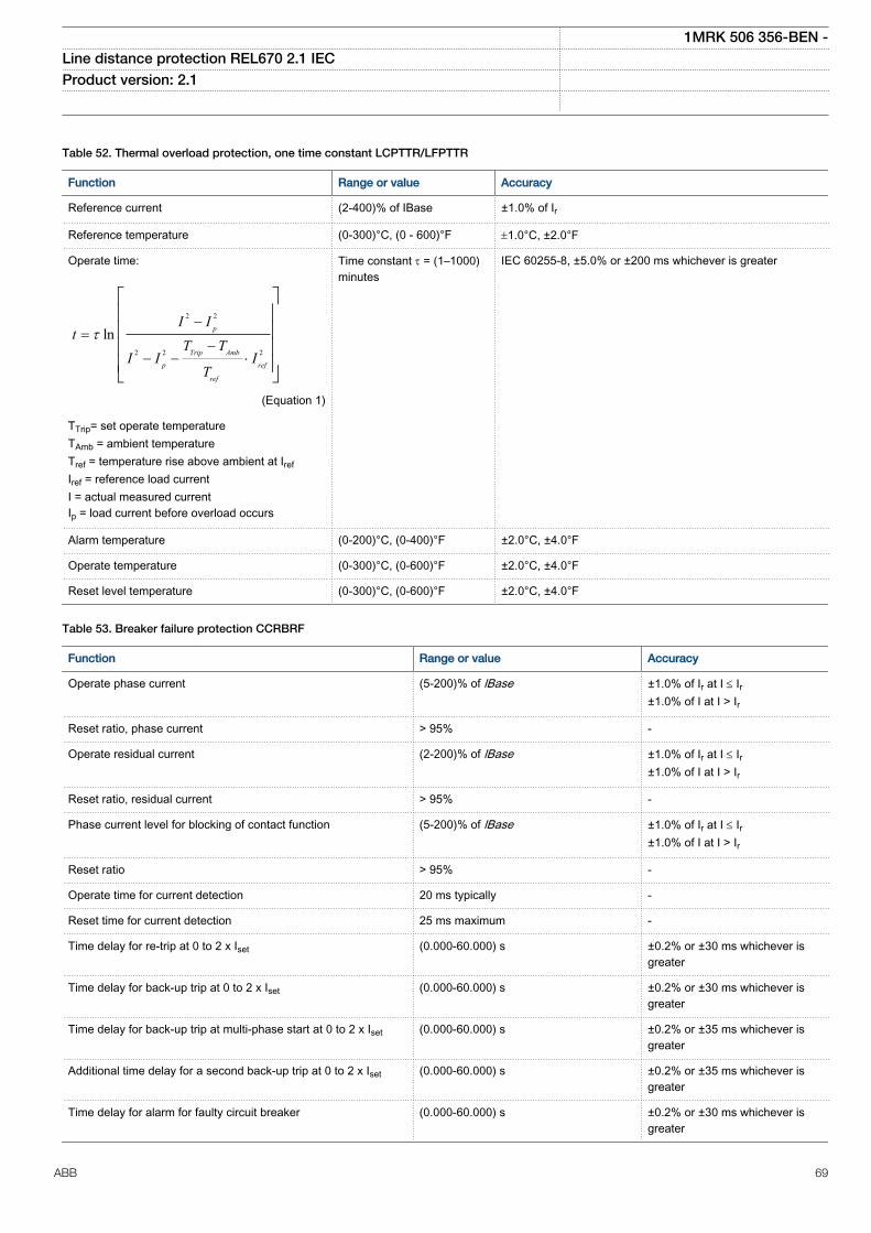
Table 52. Thermal overload protection, one time constant LCPTTR/LFPTTR
Function Range or value Accuracy
Reference current (2-400)% of IBase ±1.0% of Ir
Reference temperature (0-300)°C, (0 - 600)°F ±1.0°C, ±2.0°F
Operate time:
2 2
2 2 2
ln p
Trip Amb
p ref
ref
I It
T TI I I
T
t-
=-
- - ×
é ùê úê úê úê úë û
EQUATION13000039 V2 EN (Equation 1)
TTrip= set operate temperatureTAmb = ambient temperatureTref = temperature rise above ambient at IrefIref = reference load currentI = actual measured currentIp = load current before overload occurs
Time constant t = (1–1000)minutes
IEC 60255-8, ±5.0% or ±200 ms whichever is greater
Alarm temperature (0-200)°C, (0-400)°F ±2.0°C, ±4.0°F
Operate temperature (0-300)°C, (0-600)°F ±2.0°C, ±4.0°F
Reset level temperature (0-300)°C, (0-600)°F ±2.0°C, ±4.0°F
Table 53. Breaker failure protection CCRBRF
Function Range or value Accuracy
Operate phase current (5-200)% of lBase ±1.0% of Ir at I £ Ir±1.0% of I at I > Ir
Reset ratio, phase current > 95% -
Operate residual current (2-200)% of lBase ±1.0% of Ir at I £ Ir±1.0% of I at I > Ir
Reset ratio, residual current > 95% -
Phase current level for blocking of contact function (5-200)% of lBase ±1.0% of Ir at I £ Ir±1.0% of I at I > Ir
Reset ratio > 95% -
Operate time for current detection 20 ms typically -
Reset time for current detection 25 ms maximum -
Time delay for re-trip at 0 to 2 x Iset (0.000-60.000) s ±0.2% or ±30 ms whichever isgreater
Time delay for back-up trip at 0 to 2 x Iset (0.000-60.000) s ±0.2% or ±30 ms whichever isgreater
Time delay for back-up trip at multi-phase start at 0 to 2 x Iset (0.000-60.000) s ±0.2% or ±35 ms whichever isgreater
Additional time delay for a second back-up trip at 0 to 2 x Iset (0.000-60.000) s ±0.2% or ±35 ms whichever isgreater
Time delay for alarm for faulty circuit breaker (0.000-60.000) s ±0.2% or ±30 ms whichever isgreater
1MRK 506 356-BEN -Line distance protection REL670 2.1 IEC Product version: 2.1
ABB 69
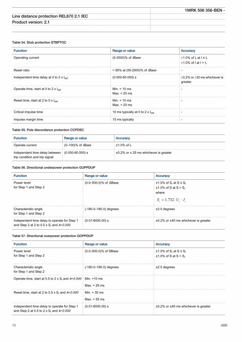
Table 54. Stub protection STBPTOC
Function Range or value Accuracy
Operating current (5-2500)% of IBase ±1.0% of Ir at I ≤ Ir±1.0% of I at I > Ir
Reset ratio > 95% at (50-2500)% of IBase -
Independent time delay at 0 to 2 x Iset (0.000-60.000) s ±0.2% or ±30 ms whichever isgreater
Operate time, start at 0 to 2 x Iset Min. = 10 msMax. = 20 ms
-
Reset time, start at 2 to 0 x Iset Min. = 10 msMax. = 20 ms
-
Critical impulse time 10 ms typically at 0 to 2 x Iset -
Impulse margin time 15 ms typically -
Table 55. Pole discordance protection CCPDSC
Function Range or value Accuracy
Operate current (0–100)% of IBase ±1.0% of Ir
Independent time delay betweentrip condition and trip signal
(0.000-60.000) s ±0.2% or ± 25 ms whichever is greater
Table 56. Directional underpower protection GUPPDUP
Function Range or value Accuracy
Power levelfor Step 1 and Step 2
(0.0–500.0)% of SBase ±1.0% of Sr at S ≤ Sr±1.0% of S at S > Srwhere
1.732r r rS U I= × ×
Characteristic anglefor Step 1 and Step 2
(-180.0–180.0) degrees ±2.0 degrees
Independent time delay to operate for Step 1and Step 2 at 2 to 0.5 x Sr and k=0.000
(0.01-6000.00) s ±0.2% or ±40 ms whichever is greater
Table 57. Directional overpower protection GOPPDOP
Function Range or value Accuracy
Power levelfor Step 1 and Step 2
(0.0–500.0)% of SBase
±1.0% of Sr at S ≤ Sr±1.0% of S at S > Sr
Characteristic anglefor Step 1 and Step 2
(-180.0–180.0) degrees ±2.0 degrees
Operate time, start at 0.5 to 2 x Sr and k=0.000 Min. =10 ms
Max. = 25 ms
Reset time, start at 2 to 0.5 x Sr and k=0.000 Min. = 35 ms
Max. = 55 ms
Independent time delay to operate for Step 1and Step 2 at 0.5 to 2 x Sr and k=0.000
(0.01-6000.00) s ±0.2% or ±40 ms whichever is greater
1MRK 506 356-BEN -Line distance protection REL670 2.1 IEC Product version: 2.1
70 ABB
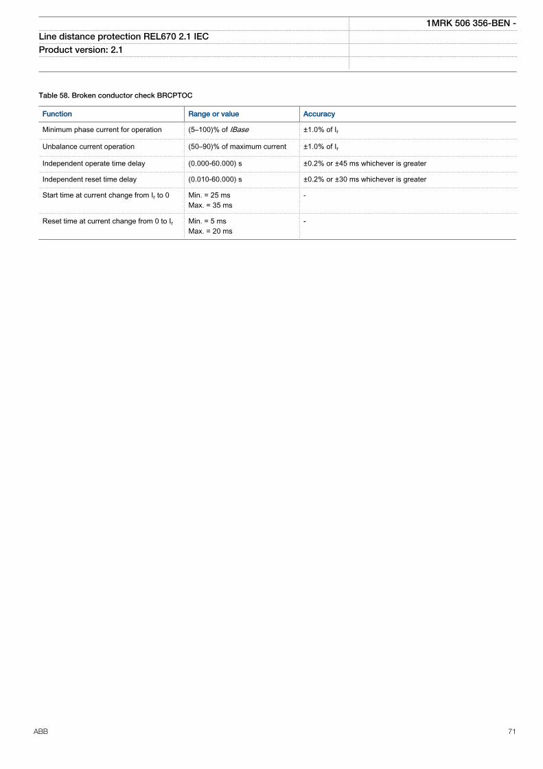
Table 58. Broken conductor check BRCPTOC
Function Range or value Accuracy
Minimum phase current for operation (5–100)% of IBase ±1.0% of Ir
Unbalance current operation (50–90)% of maximum current ±1.0% of Ir
Independent operate time delay (0.000-60.000) s ±0.2% or ±45 ms whichever is greater
Independent reset time delay (0.010-60.000) s ±0.2% or ±30 ms whichever is greater
Start time at current change from Ir to 0 Min. = 25 msMax. = 35 ms
-
Reset time at current change from 0 to Ir Min. = 5 msMax. = 20 ms
-
1MRK 506 356-BEN -Line distance protection REL670 2.1 IEC Product version: 2.1
ABB 71
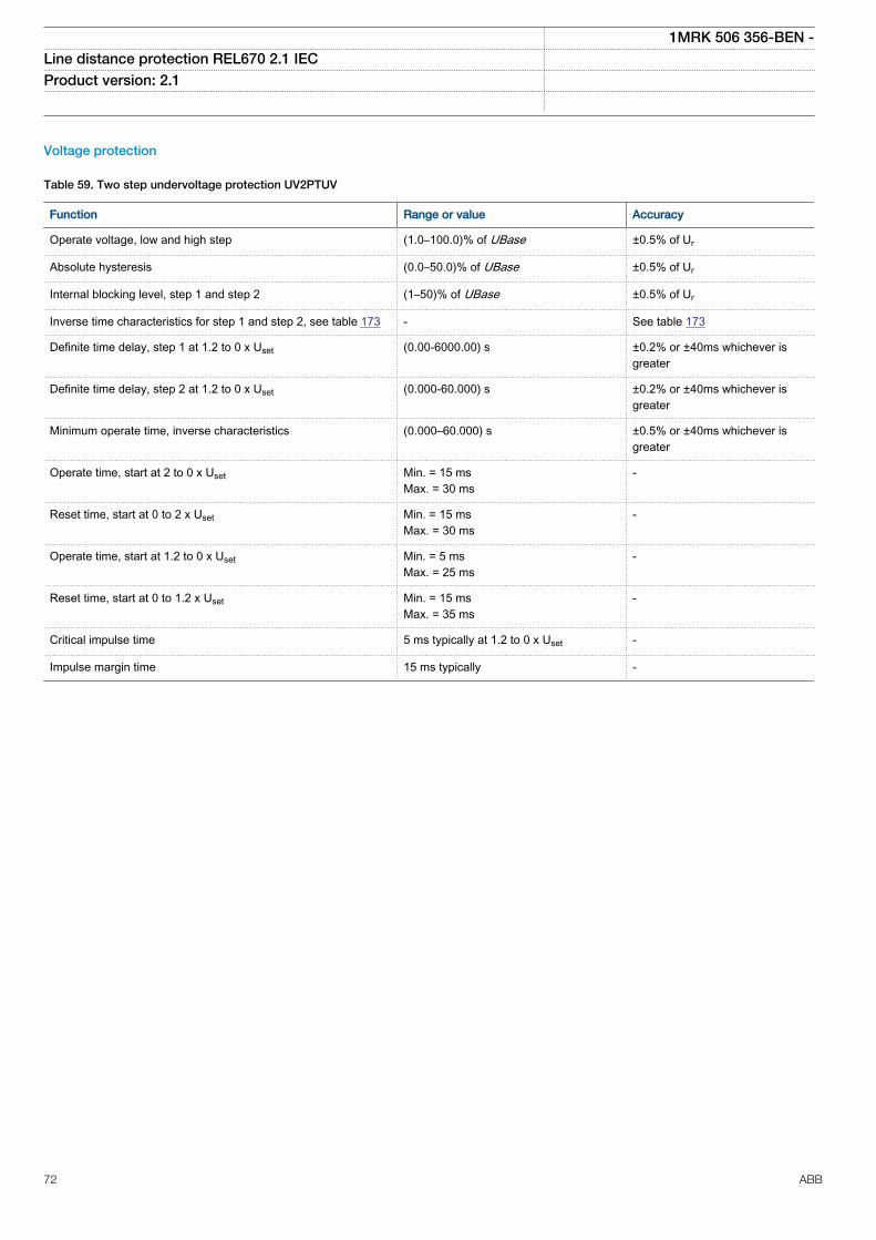
Voltage protection
Table 59. Two step undervoltage protection UV2PTUV
Function Range or value Accuracy
Operate voltage, low and high step (1.0–100.0)% of UBase ±0.5% of Ur
Absolute hysteresis (0.0–50.0)% of UBase ±0.5% of Ur
Internal blocking level, step 1 and step 2 (1–50)% of UBase ±0.5% of Ur
Inverse time characteristics for step 1 and step 2, see table 173 - See table 173
Definite time delay, step 1 at 1.2 to 0 x Uset (0.00-6000.00) s ±0.2% or ±40ms whichever isgreater
Definite time delay, step 2 at 1.2 to 0 x Uset (0.000-60.000) s ±0.2% or ±40ms whichever isgreater
Minimum operate time, inverse characteristics (0.000–60.000) s ±0.5% or ±40ms whichever isgreater
Operate time, start at 2 to 0 x Uset Min. = 15 msMax. = 30 ms
-
Reset time, start at 0 to 2 x Uset Min. = 15 msMax. = 30 ms
-
Operate time, start at 1.2 to 0 x Uset Min. = 5 msMax. = 25 ms
-
Reset time, start at 0 to 1.2 x Uset Min. = 15 msMax. = 35 ms
-
Critical impulse time 5 ms typically at 1.2 to 0 x Uset -
Impulse margin time 15 ms typically -
1MRK 506 356-BEN -Line distance protection REL670 2.1 IEC Product version: 2.1
72 ABB
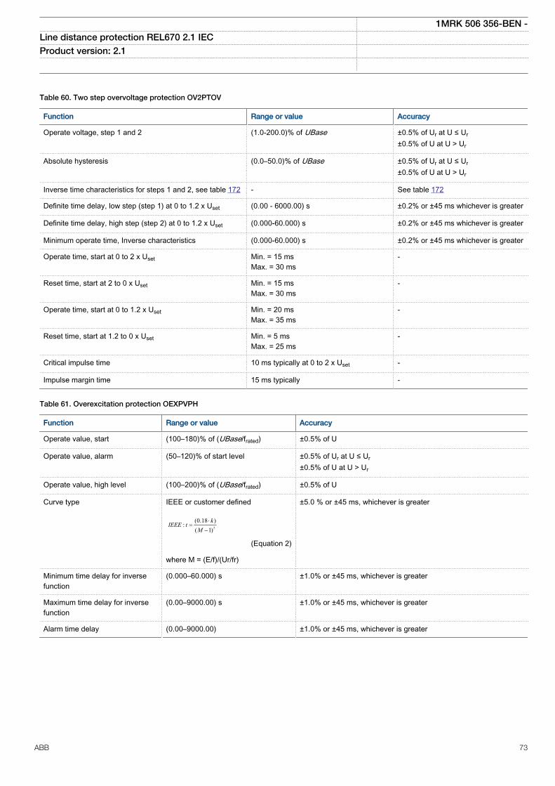
Table 60. Two step overvoltage protection OV2PTOV
Function Range or value Accuracy
Operate voltage, step 1 and 2 (1.0-200.0)% of UBase ±0.5% of Ur at U ≤ Ur±0.5% of U at U > Ur
Absolute hysteresis (0.0–50.0)% of UBase ±0.5% of Ur at U ≤ Ur±0.5% of U at U > Ur
Inverse time characteristics for steps 1 and 2, see table 172 - See table 172
Definite time delay, low step (step 1) at 0 to 1.2 x Uset (0.00 - 6000.00) s ±0.2% or ±45 ms whichever is greater
Definite time delay, high step (step 2) at 0 to 1.2 x Uset (0.000-60.000) s ±0.2% or ±45 ms whichever is greater
Minimum operate time, Inverse characteristics (0.000-60.000) s ±0.2% or ±45 ms whichever is greater
Operate time, start at 0 to 2 x Uset Min. = 15 msMax. = 30 ms
-
Reset time, start at 2 to 0 x Uset Min. = 15 msMax. = 30 ms
-
Operate time, start at 0 to 1.2 x Uset Min. = 20 msMax. = 35 ms
-
Reset time, start at 1.2 to 0 x Uset Min. = 5 msMax. = 25 ms
-
Critical impulse time 10 ms typically at 0 to 2 x Uset -
Impulse margin time 15 ms typically -
Table 61. Overexcitation protection OEXPVPH
Function Range or value Accuracy
Operate value, start (100–180)% of (UBase/frated) ±0.5% of U
Operate value, alarm (50–120)% of start level ±0.5% of Ur at U ≤ Ur±0.5% of U at U > Ur
Operate value, high level (100–200)% of (UBase/frated) ±0.5% of U
Curve type IEEE or customer defined
2
(0.18 ):
( 1)k
IEEE tM
×=
-
EQUATION1319 V1 EN (Equation 2)
where M = (E/f)/(Ur/fr)
±5.0 % or ±45 ms, whichever is greater
Minimum time delay for inversefunction
(0.000–60.000) s ±1.0% or ±45 ms, whichever is greater
Maximum time delay for inversefunction
(0.00–9000.00) s ±1.0% or ±45 ms, whichever is greater
Alarm time delay (0.00–9000.00) ±1.0% or ±45 ms, whichever is greater
1MRK 506 356-BEN -Line distance protection REL670 2.1 IEC Product version: 2.1
ABB 73
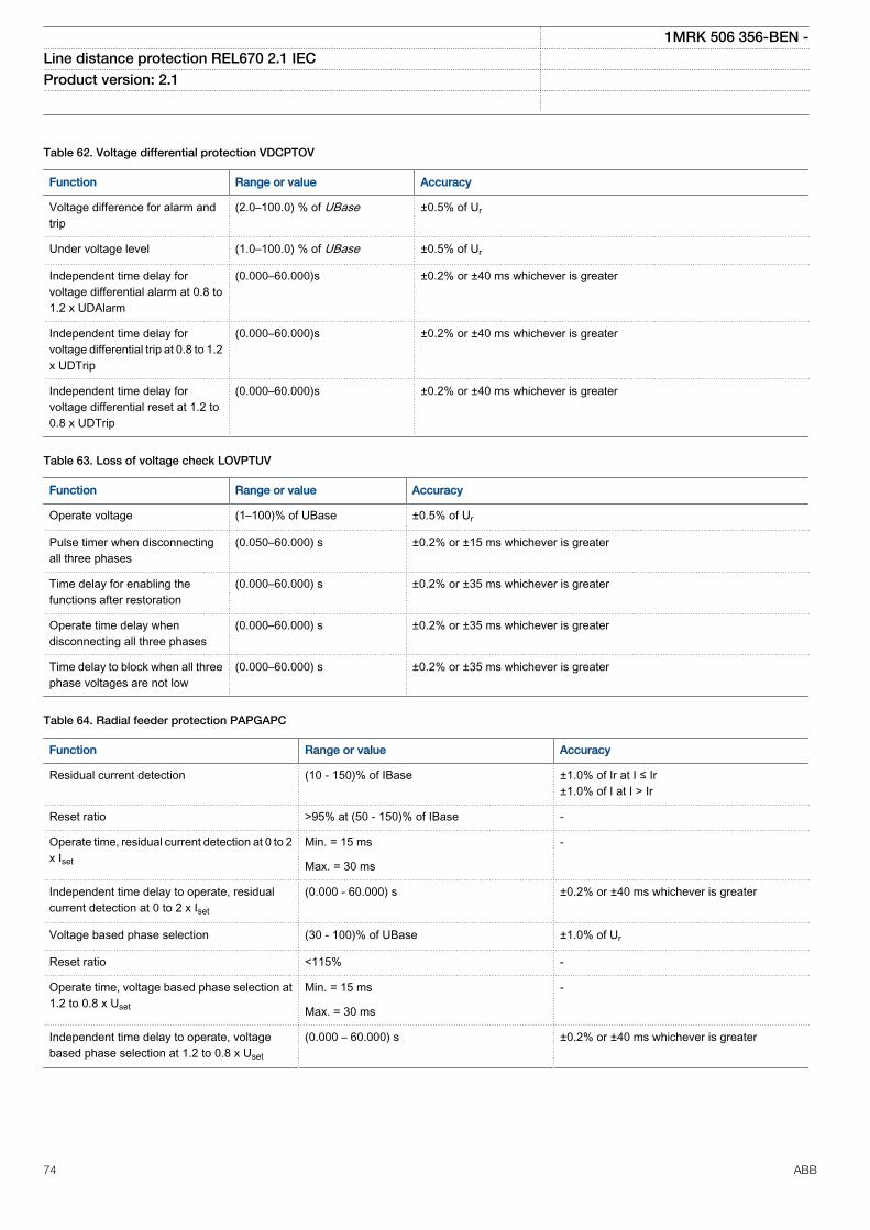
Table 62. Voltage differential protection VDCPTOV
Function Range or value Accuracy
Voltage difference for alarm andtrip
(2.0–100.0) % of UBase ±0.5% of Ur
Under voltage level (1.0–100.0) % of UBase ±0.5% of Ur
Independent time delay forvoltage differential alarm at 0.8 to1.2 x UDAlarm
(0.000–60.000)s ±0.2% or ±40 ms whichever is greater
Independent time delay forvoltage differential trip at 0.8 to 1.2x UDTrip
(0.000–60.000)s ±0.2% or ±40 ms whichever is greater
Independent time delay forvoltage differential reset at 1.2 to0.8 x UDTrip
(0.000–60.000)s ±0.2% or ±40 ms whichever is greater
Table 63. Loss of voltage check LOVPTUV
Function Range or value Accuracy
Operate voltage (1–100)% of UBase ±0.5% of Ur
Pulse timer when disconnectingall three phases
(0.050–60.000) s ±0.2% or ±15 ms whichever is greater
Time delay for enabling thefunctions after restoration
(0.000–60.000) s ±0.2% or ±35 ms whichever is greater
Operate time delay whendisconnecting all three phases
(0.000–60.000) s ±0.2% or ±35 ms whichever is greater
Time delay to block when all threephase voltages are not low
(0.000–60.000) s ±0.2% or ±35 ms whichever is greater
Table 64. Radial feeder protection PAPGAPC
Function Range or value Accuracy
Residual current detection (10 - 150)% of IBase ±1.0% of Ir at I ≤ Ir±1.0% of I at I > Ir
Reset ratio >95% at (50 - 150)% of IBase -
Operate time, residual current detection at 0 to 2x Iset
Min. = 15 ms -
Max. = 30 ms
Independent time delay to operate, residualcurrent detection at 0 to 2 x Iset
(0.000 - 60.000) s ±0.2% or ±40 ms whichever is greater
Voltage based phase selection (30 - 100)% of UBase ±1.0% of Ur
Reset ratio <115% -
Operate time, voltage based phase selection at1.2 to 0.8 x Uset
Min. = 15 ms -
Max. = 30 ms
Independent time delay to operate, voltagebased phase selection at 1.2 to 0.8 x Uset
(0.000 – 60.000) s ±0.2% or ±40 ms whichever is greater
1MRK 506 356-BEN -Line distance protection REL670 2.1 IEC Product version: 2.1
74 ABB
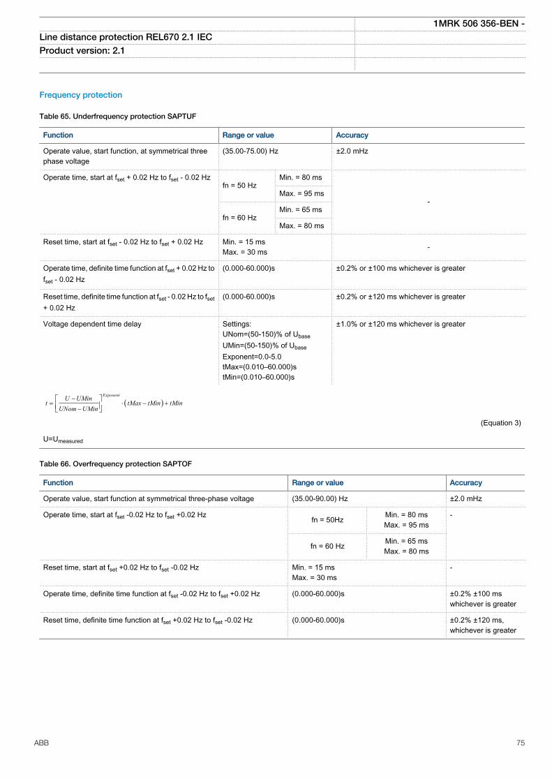
Frequency protection
Table 65. Underfrequency protection SAPTUF
Function Range or value Accuracy
Operate value, start function, at symmetrical threephase voltage
(35.00-75.00) Hz ±2.0 mHz
Operate time, start at fset + 0.02 Hz to fset - 0.02 Hzfn = 50 Hz
Min. = 80 ms
-Max. = 95 ms
fn = 60 HzMin. = 65 ms
Max. = 80 ms
Reset time, start at fset - 0.02 Hz to fset + 0.02 Hz Min. = 15 msMax. = 30 ms -
Operate time, definite time function at fset + 0.02 Hz tofset - 0.02 Hz
(0.000-60.000)s ±0.2% or ±100 ms whichever is greater
Reset time, definite time function at fset - 0.02 Hz to fset+ 0.02 Hz
(0.000-60.000)s ±0.2% or ±120 ms whichever is greater
Voltage dependent time delay Settings:UNom=(50-150)% of UbaseUMin=(50-150)% of UbaseExponent=0.0-5.0tMax=(0.010–60.000)stMin=(0.010–60.000)s
±1.0% or ±120 ms whichever is greater
( )ExponentU UMin
t tMax tMin tMinUNom UMin
-= × - +
-é ùê úë û
EQUATION1182 V1 EN (Equation 3)
U=Umeasured
Table 66. Overfrequency protection SAPTOF
Function Range or value Accuracy
Operate value, start function at symmetrical three-phase voltage (35.00-90.00) Hz ±2.0 mHz
Operate time, start at fset -0.02 Hz to fset +0.02 Hz fn = 50Hz Min. = 80 msMax. = 95 ms
-
fn = 60 Hz Min. = 65 msMax. = 80 ms
Reset time, start at fset +0.02 Hz to fset -0.02 Hz Min. = 15 msMax. = 30 ms
-
Operate time, definite time function at fset -0.02 Hz to fset +0.02 Hz (0.000-60.000)s ±0.2% ±100 mswhichever is greater
Reset time, definite time function at fset +0.02 Hz to fset -0.02 Hz (0.000-60.000)s ±0.2% ±120 ms,whichever is greater
1MRK 506 356-BEN -Line distance protection REL670 2.1 IEC Product version: 2.1
ABB 75
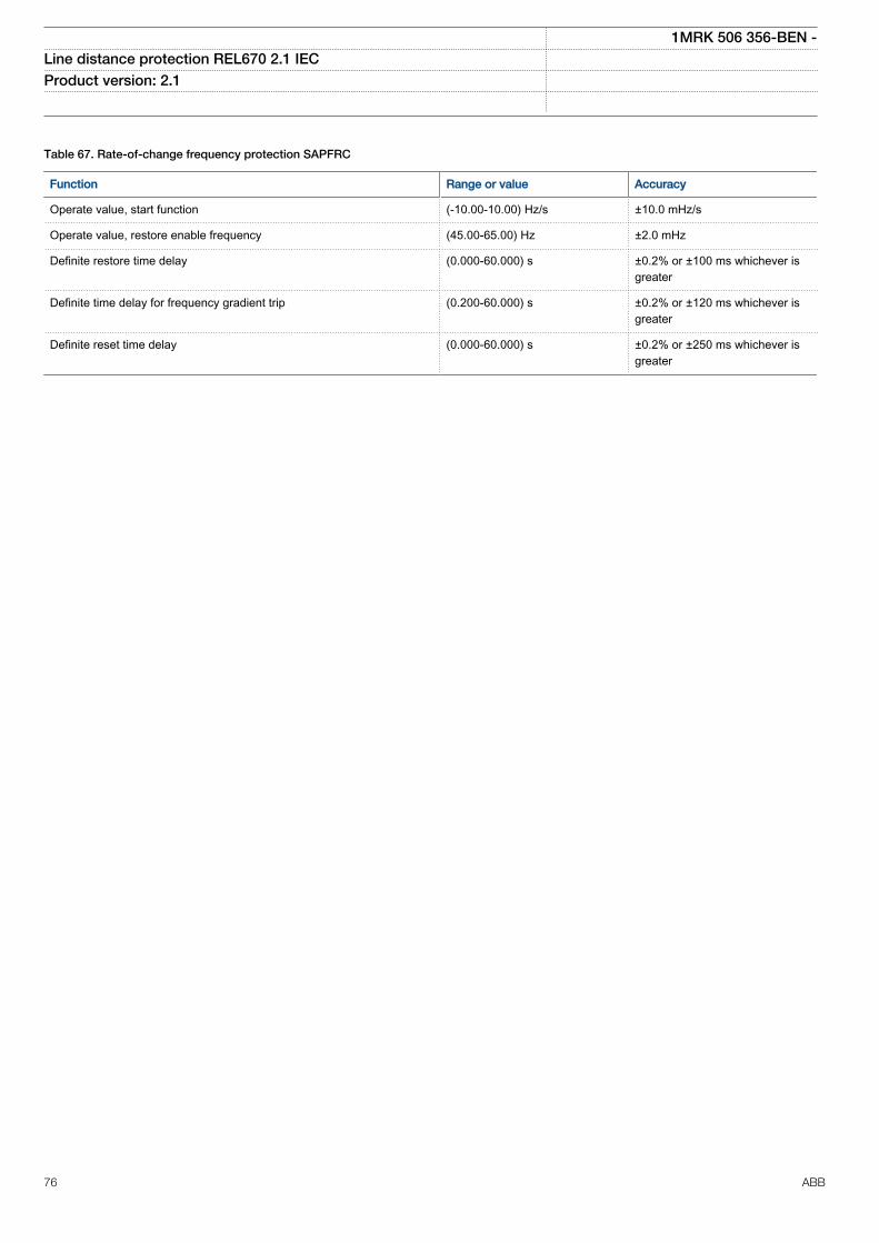
Table 67. Rate-of-change frequency protection SAPFRC
Function Range or value Accuracy
Operate value, start function (-10.00-10.00) Hz/s ±10.0 mHz/s
Operate value, restore enable frequency (45.00-65.00) Hz ±2.0 mHz
Definite restore time delay (0.000-60.000) s ±0.2% or ±100 ms whichever isgreater
Definite time delay for frequency gradient trip (0.200-60.000) s ±0.2% or ±120 ms whichever isgreater
Definite reset time delay (0.000-60.000) s ±0.2% or ±250 ms whichever isgreater
1MRK 506 356-BEN -Line distance protection REL670 2.1 IEC Product version: 2.1
76 ABB
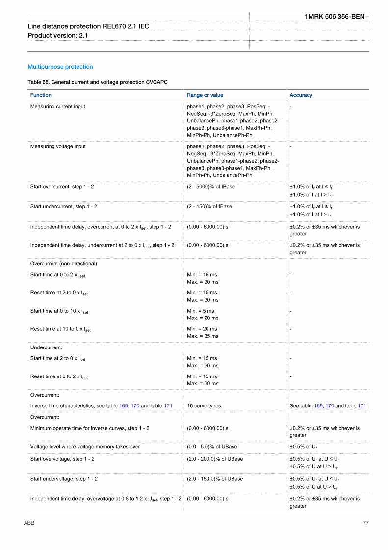
Multipurpose protection
Table 68. General current and voltage protection CVGAPC
Function Range or value Accuracy
Measuring current input phase1, phase2, phase3, PosSeq, -NegSeq, -3*ZeroSeq, MaxPh, MinPh,UnbalancePh, phase1-phase2, phase2-phase3, phase3-phase1, MaxPh-Ph,MinPh-Ph, UnbalancePh-Ph
-
Measuring voltage input phase1, phase2, phase3, PosSeq, -NegSeq, -3*ZeroSeq, MaxPh, MinPh,UnbalancePh, phase1-phase2, phase2-phase3, phase3-phase1, MaxPh-Ph,MinPh-Ph, UnbalancePh-Ph
-
Start overcurrent, step 1 - 2 (2 - 5000)% of IBase ±1.0% of Ir at I ≤ Ir±1.0% of I at I > Ir
Start undercurrent, step 1 - 2 (2 - 150)% of IBase ±1.0% of Ir at I ≤ Ir±1.0% of I at I > Ir
Independent time delay, overcurrent at 0 to 2 x Iset, step 1 - 2 (0.00 - 6000.00) s ±0.2% or ±35 ms whichever isgreater
Independent time delay, undercurrent at 2 to 0 x Iset, step 1 - 2 (0.00 - 6000.00) s ±0.2% or ±35 ms whichever isgreater
Overcurrent (non-directional):
Start time at 0 to 2 x Iset Min. = 15 msMax. = 30 ms
-
Reset time at 2 to 0 x Iset Min. = 15 msMax. = 30 ms
-
Start time at 0 to 10 x Iset Min. = 5 msMax. = 20 ms
-
Reset time at 10 to 0 x Iset Min. = 20 msMax. = 35 ms
-
Undercurrent:
Start time at 2 to 0 x Iset Min. = 15 msMax. = 30 ms
-
Reset time at 0 to 2 x Iset Min. = 15 msMax. = 30 ms
-
Overcurrent:
Inverse time characteristics, see table 169, 170 and table 171 16 curve types See table 169, 170 and table 171
Overcurrent:
Minimum operate time for inverse curves, step 1 - 2 (0.00 - 6000.00) s ±0.2% or ±35 ms whichever isgreater
Voltage level where voltage memory takes over (0.0 - 5.0)% of UBase ±0.5% of Ur
Start overvoltage, step 1 - 2 (2.0 - 200.0)% of UBase ±0.5% of Ur at U ≤ Ur±0.5% of U at U > Ur
Start undervoltage, step 1 - 2 (2.0 - 150.0)% of UBase ±0.5% of Ur at U ≤ Ur±0.5% of U at U > Ur
Independent time delay, overvoltage at 0.8 to 1.2 x Uset, step 1 - 2 (0.00 - 6000.00) s ±0.2% or ±35 ms whichever isgreater
1MRK 506 356-BEN -Line distance protection REL670 2.1 IEC Product version: 2.1
ABB 77
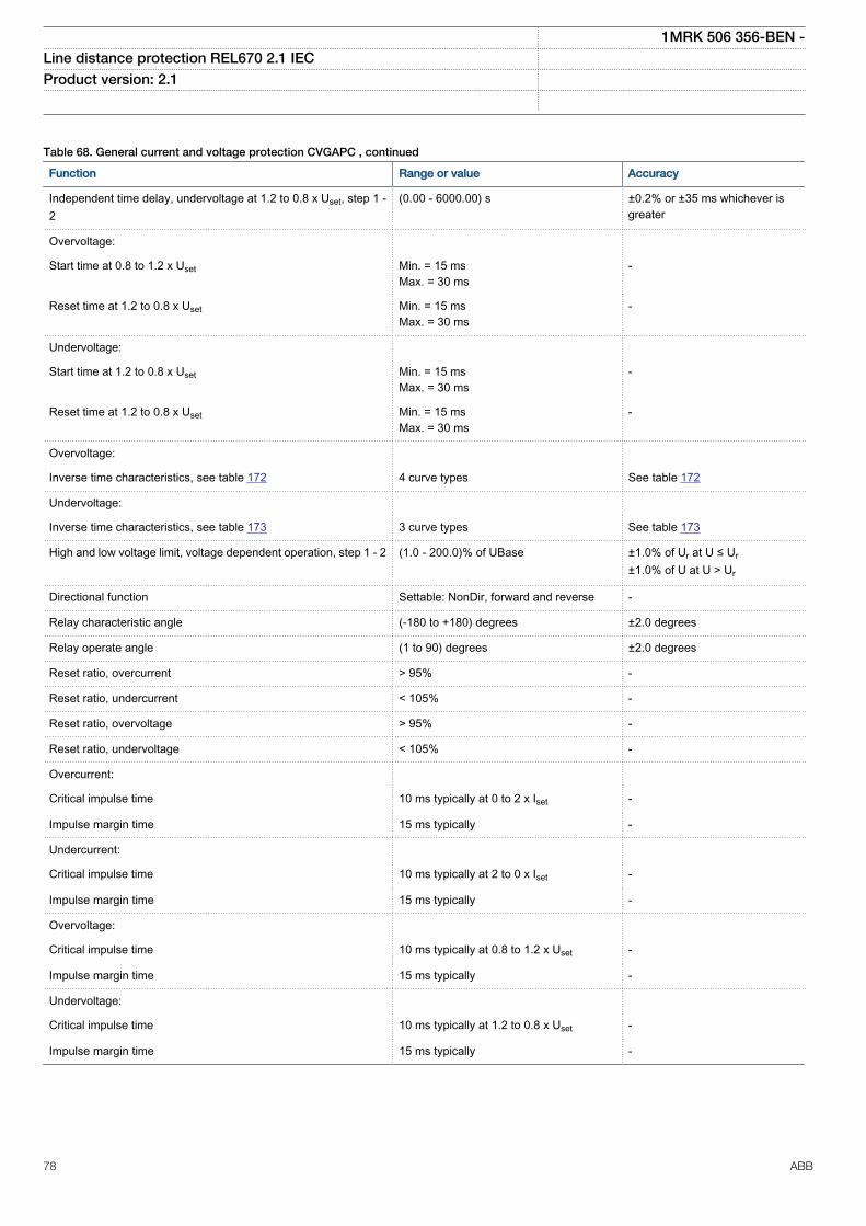
Table 68. General current and voltage protection CVGAPC , continued
Function Range or value Accuracy
Independent time delay, undervoltage at 1.2 to 0.8 x Uset, step 1 -2
(0.00 - 6000.00) s ±0.2% or ±35 ms whichever isgreater
Overvoltage:
Start time at 0.8 to 1.2 x Uset Min. = 15 msMax. = 30 ms
-
Reset time at 1.2 to 0.8 x Uset Min. = 15 msMax. = 30 ms
-
Undervoltage:
Start time at 1.2 to 0.8 x Uset Min. = 15 msMax. = 30 ms
-
Reset time at 1.2 to 0.8 x Uset Min. = 15 msMax. = 30 ms
-
Overvoltage:
Inverse time characteristics, see table 172 4 curve types See table 172
Undervoltage:
Inverse time characteristics, see table 173 3 curve types See table 173
High and low voltage limit, voltage dependent operation, step 1 - 2 (1.0 - 200.0)% of UBase ±1.0% of Ur at U ≤ Ur±1.0% of U at U > Ur
Directional function Settable: NonDir, forward and reverse -
Relay characteristic angle (-180 to +180) degrees ±2.0 degrees
Relay operate angle (1 to 90) degrees ±2.0 degrees
Reset ratio, overcurrent > 95% -
Reset ratio, undercurrent < 105% -
Reset ratio, overvoltage > 95% -
Reset ratio, undervoltage < 105% -
Overcurrent:
Critical impulse time 10 ms typically at 0 to 2 x Iset -
Impulse margin time 15 ms typically -
Undercurrent:
Critical impulse time 10 ms typically at 2 to 0 x Iset -
Impulse margin time 15 ms typically -
Overvoltage:
Critical impulse time 10 ms typically at 0.8 to 1.2 x Uset -
Impulse margin time 15 ms typically -
Undervoltage:
Critical impulse time 10 ms typically at 1.2 to 0.8 x Uset -
Impulse margin time 15 ms typically -
1MRK 506 356-BEN -Line distance protection REL670 2.1 IEC Product version: 2.1
78 ABB
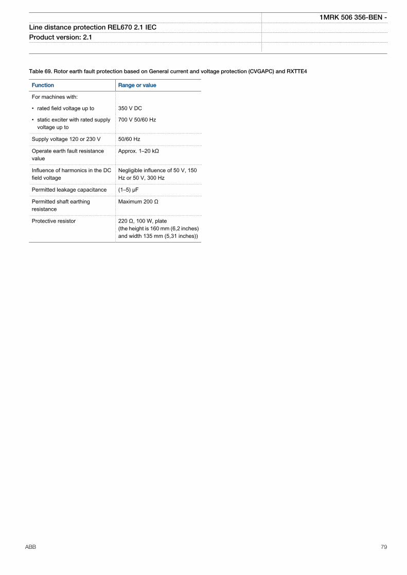
Table 69. Rotor earth fault protection based on General current and voltage protection (CVGAPC) and RXTTE4
Function Range or value
For machines with:
• rated field voltage up to 350 V DC
• static exciter with rated supplyvoltage up to
700 V 50/60 Hz
Supply voltage 120 or 230 V 50/60 Hz
Operate earth fault resistancevalue
Approx. 1–20 kΩ
Influence of harmonics in the DCfield voltage
Negligible influence of 50 V, 150Hz or 50 V, 300 Hz
Permitted leakage capacitance (1–5) μF
Permitted shaft earthingresistance
Maximum 200 Ω
Protective resistor 220 Ω, 100 W, plate(the height is 160 mm (6,2 inches)and width 135 mm (5,31 inches))
1MRK 506 356-BEN -Line distance protection REL670 2.1 IEC Product version: 2.1
ABB 79
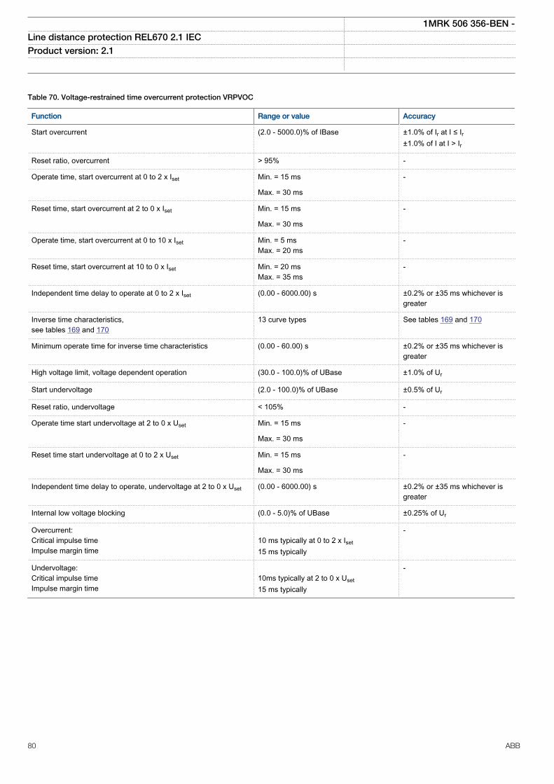
Table 70. Voltage-restrained time overcurrent protection VRPVOC
Function Range or value Accuracy
Start overcurrent (2.0 - 5000.0)% of IBase ±1.0% of Ir at I ≤ Ir±1.0% of I at I > Ir
Reset ratio, overcurrent > 95% -
Operate time, start overcurrent at 0 to 2 x Iset Min. = 15 ms -
Max. = 30 ms
Reset time, start overcurrent at 2 to 0 x Iset Min. = 15 ms -
Max. = 30 ms
Operate time, start overcurrent at 0 to 10 x Iset Min. = 5 msMax. = 20 ms
-
Reset time, start overcurrent at 10 to 0 x Iset Min. = 20 msMax. = 35 ms
-
Independent time delay to operate at 0 to 2 x Iset (0.00 - 6000.00) s ±0.2% or ±35 ms whichever isgreater
Inverse time characteristics,see tables 169 and 170
13 curve types See tables 169 and 170
Minimum operate time for inverse time characteristics (0.00 - 60.00) s ±0.2% or ±35 ms whichever isgreater
High voltage limit, voltage dependent operation (30.0 - 100.0)% of UBase ±1.0% of Ur
Start undervoltage (2.0 - 100.0)% of UBase ±0.5% of Ur
Reset ratio, undervoltage < 105% -
Operate time start undervoltage at 2 to 0 x Uset Min. = 15 ms -
Max. = 30 ms
Reset time start undervoltage at 0 to 2 x Uset Min. = 15 ms -
Max. = 30 ms
Independent time delay to operate, undervoltage at 2 to 0 x Uset (0.00 - 6000.00) s ±0.2% or ±35 ms whichever isgreater
Internal low voltage blocking (0.0 - 5.0)% of UBase ±0.25% of Ur
Overcurrent:Critical impulse timeImpulse margin time
10 ms typically at 0 to 2 x Iset15 ms typically
-
Undervoltage:Critical impulse timeImpulse margin time
10ms typically at 2 to 0 x Uset15 ms typically
-
1MRK 506 356-BEN -Line distance protection REL670 2.1 IEC Product version: 2.1
80 ABB
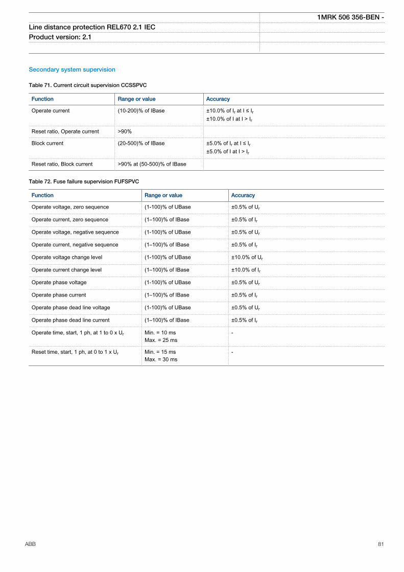
Secondary system supervision
Table 71. Current circuit supervision CCSSPVC
Function Range or value Accuracy
Operate current (10-200)% of IBase ±10.0% of Ir at I ≤ Ir±10.0% of I at I > Ir
Reset ratio, Operate current >90%
Block current (20-500)% of IBase ±5.0% of Ir at I ≤ Ir±5.0% of I at I > Ir
Reset ratio, Block current >90% at (50-500)% of IBase
Table 72. Fuse failure supervision FUFSPVC
Function Range or value Accuracy
Operate voltage, zero sequence (1-100)% of UBase ±0.5% of Ur
Operate current, zero sequence (1–100)% of IBase ±0.5% of Ir
Operate voltage, negative sequence (1-100)% of UBase ±0.5% of Ur
Operate current, negative sequence (1–100)% of IBase ±0.5% of Ir
Operate voltage change level (1-100)% of UBase ±10.0% of Ur
Operate current change level (1–100)% of IBase ±10.0% of Ir
Operate phase voltage (1-100)% of UBase ±0.5% of Ur
Operate phase current (1–100)% of IBase ±0.5% of Ir
Operate phase dead line voltage (1-100)% of UBase ±0.5% of Ur
Operate phase dead line current (1–100)% of IBase ±0.5% of Ir
Operate time, start, 1 ph, at 1 to 0 x Ur Min. = 10 msMax. = 25 ms
-
Reset time, start, 1 ph, at 0 to 1 x Ur Min. = 15 msMax. = 30 ms
-
1MRK 506 356-BEN -Line distance protection REL670 2.1 IEC Product version: 2.1
ABB 81
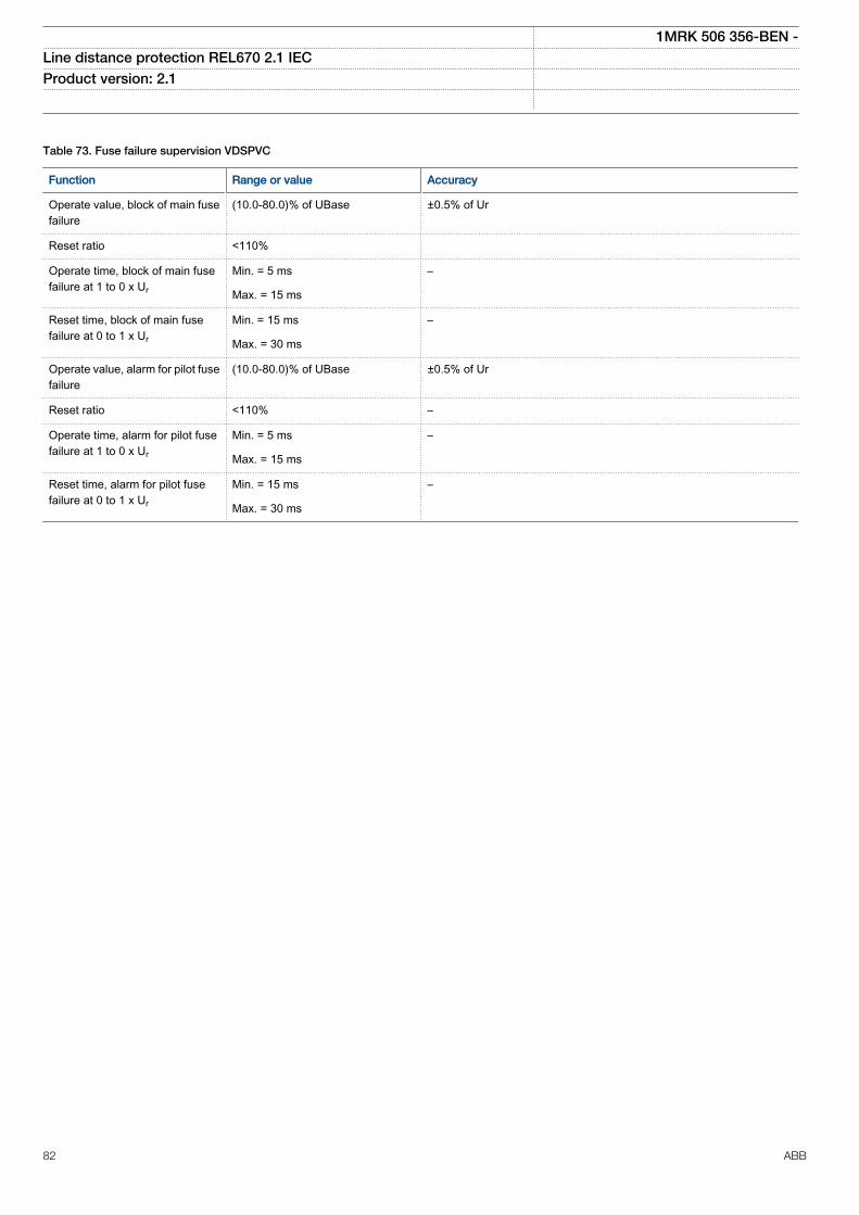
Table 73. Fuse failure supervision VDSPVC
Function Range or value Accuracy
Operate value, block of main fusefailure
(10.0-80.0)% of UBase ±0.5% of Ur
Reset ratio <110%
Operate time, block of main fusefailure at 1 to 0 x Ur
Min. = 5 ms –
Max. = 15 ms
Reset time, block of main fusefailure at 0 to 1 x Ur
Min. = 15 ms –
Max. = 30 ms
Operate value, alarm for pilot fusefailure
(10.0-80.0)% of UBase ±0.5% of Ur
Reset ratio <110% –
Operate time, alarm for pilot fusefailure at 1 to 0 x Ur
Min. = 5 ms –
Max. = 15 ms
Reset time, alarm for pilot fusefailure at 0 to 1 x Ur
Min. = 15 ms –
Max. = 30 ms
1MRK 506 356-BEN -Line distance protection REL670 2.1 IEC Product version: 2.1
82 ABB
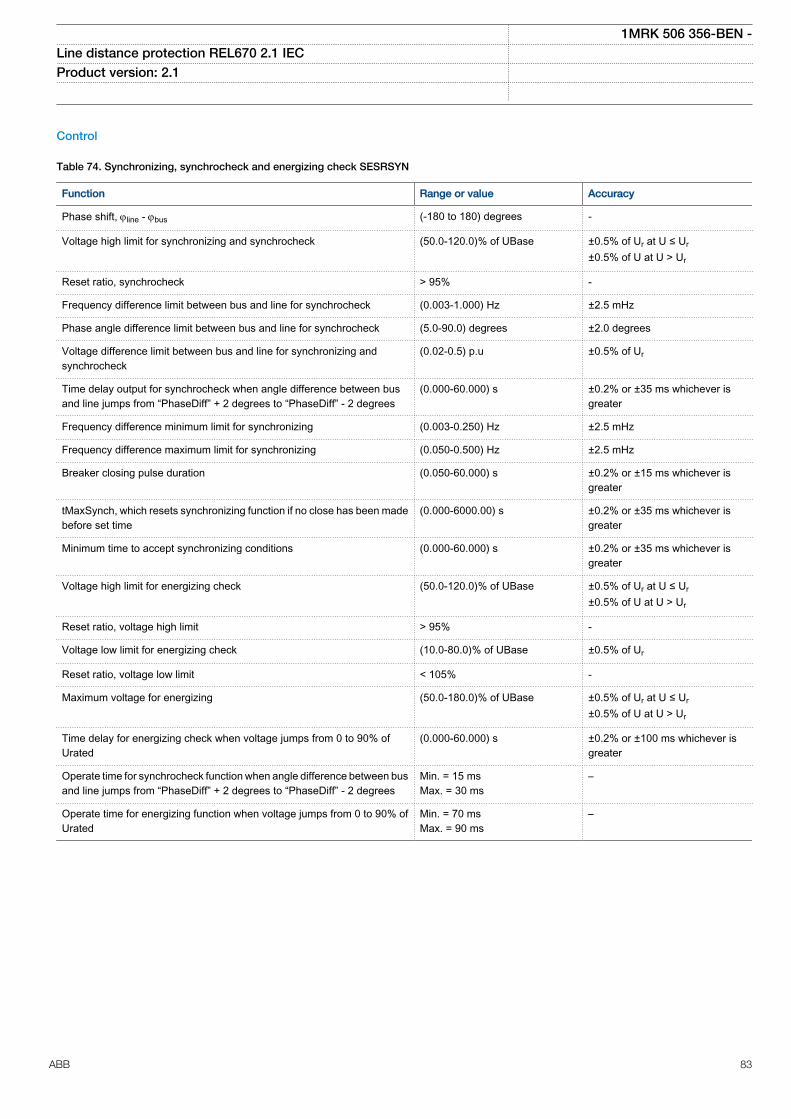
Control
Table 74. Synchronizing, synchrocheck and energizing check SESRSYN
Function Range or value Accuracy
Phase shift, jline - jbus (-180 to 180) degrees -
Voltage high limit for synchronizing and synchrocheck (50.0-120.0)% of UBase ±0.5% of Ur at U ≤ Ur±0.5% of U at U > Ur
Reset ratio, synchrocheck > 95% -
Frequency difference limit between bus and line for synchrocheck (0.003-1.000) Hz ±2.5 mHz
Phase angle difference limit between bus and line for synchrocheck (5.0-90.0) degrees ±2.0 degrees
Voltage difference limit between bus and line for synchronizing andsynchrocheck
(0.02-0.5) p.u ±0.5% of Ur
Time delay output for synchrocheck when angle difference between busand line jumps from “PhaseDiff” + 2 degrees to “PhaseDiff” - 2 degrees
(0.000-60.000) s ±0.2% or ±35 ms whichever isgreater
Frequency difference minimum limit for synchronizing (0.003-0.250) Hz ±2.5 mHz
Frequency difference maximum limit for synchronizing (0.050-0.500) Hz ±2.5 mHz
Breaker closing pulse duration (0.050-60.000) s ±0.2% or ±15 ms whichever isgreater
tMaxSynch, which resets synchronizing function if no close has been madebefore set time
(0.000-6000.00) s ±0.2% or ±35 ms whichever isgreater
Minimum time to accept synchronizing conditions (0.000-60.000) s ±0.2% or ±35 ms whichever isgreater
Voltage high limit for energizing check (50.0-120.0)% of UBase ±0.5% of Ur at U ≤ Ur±0.5% of U at U > Ur
Reset ratio, voltage high limit > 95% -
Voltage low limit for energizing check (10.0-80.0)% of UBase ±0.5% of Ur
Reset ratio, voltage low limit < 105% -
Maximum voltage for energizing (50.0-180.0)% of UBase ±0.5% of Ur at U ≤ Ur±0.5% of U at U > Ur
Time delay for energizing check when voltage jumps from 0 to 90% ofUrated
(0.000-60.000) s ±0.2% or ±100 ms whichever isgreater
Operate time for synchrocheck function when angle difference between busand line jumps from “PhaseDiff” + 2 degrees to “PhaseDiff” - 2 degrees
Min. = 15 msMax. = 30 ms
–
Operate time for energizing function when voltage jumps from 0 to 90% ofUrated
Min. = 70 msMax. = 90 ms
–
1MRK 506 356-BEN -Line distance protection REL670 2.1 IEC Product version: 2.1
ABB 83
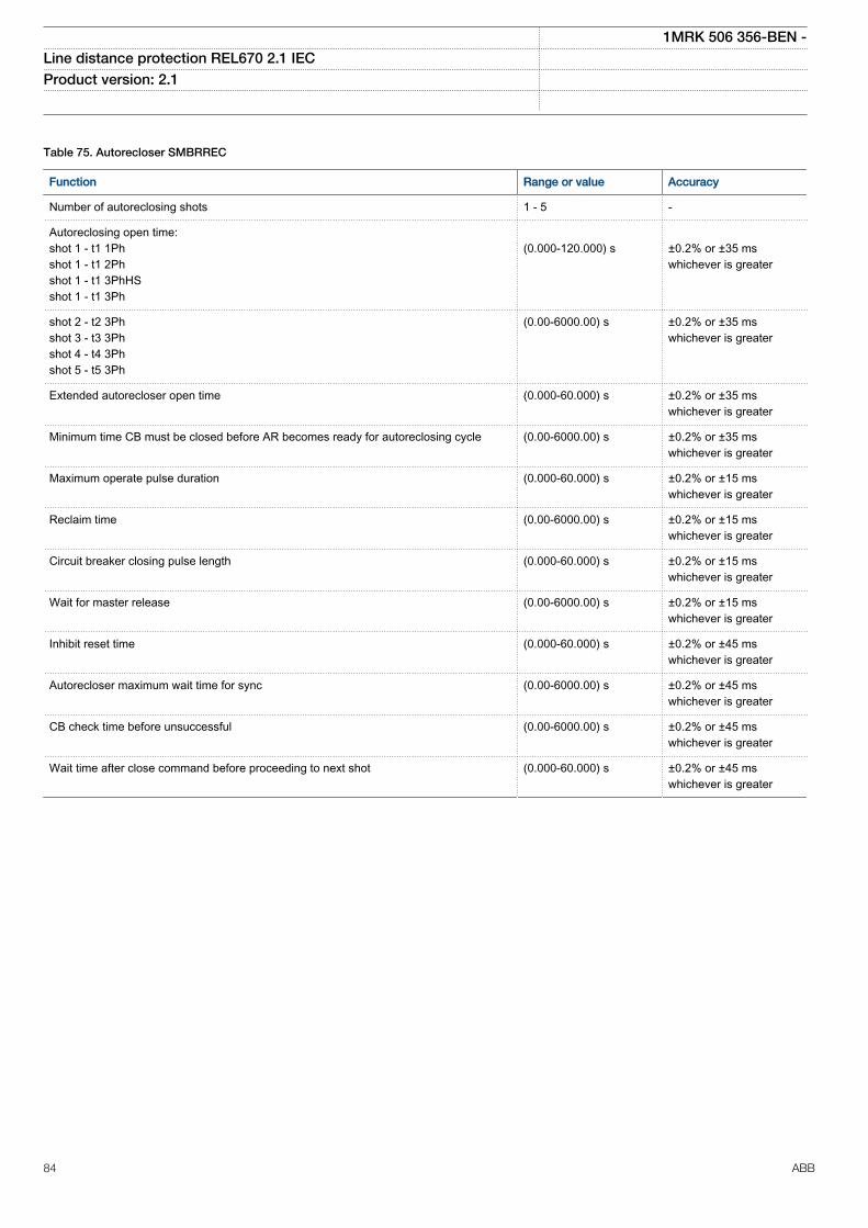
Table 75. Autorecloser SMBRREC
Function Range or value Accuracy
Number of autoreclosing shots 1 - 5 -
Autoreclosing open time:shot 1 - t1 1Phshot 1 - t1 2Phshot 1 - t1 3PhHSshot 1 - t1 3Ph
(0.000-120.000) s
±0.2% or ±35 mswhichever is greater
shot 2 - t2 3Phshot 3 - t3 3Phshot 4 - t4 3Phshot 5 - t5 3Ph
(0.00-6000.00) s ±0.2% or ±35 mswhichever is greater
Extended autorecloser open time (0.000-60.000) s ±0.2% or ±35 mswhichever is greater
Minimum time CB must be closed before AR becomes ready for autoreclosing cycle (0.00-6000.00) s ±0.2% or ±35 mswhichever is greater
Maximum operate pulse duration (0.000-60.000) s ±0.2% or ±15 mswhichever is greater
Reclaim time (0.00-6000.00) s ±0.2% or ±15 mswhichever is greater
Circuit breaker closing pulse length (0.000-60.000) s ±0.2% or ±15 mswhichever is greater
Wait for master release (0.00-6000.00) s ±0.2% or ±15 mswhichever is greater
Inhibit reset time (0.000-60.000) s ±0.2% or ±45 mswhichever is greater
Autorecloser maximum wait time for sync (0.00-6000.00) s ±0.2% or ±45 mswhichever is greater
CB check time before unsuccessful (0.00-6000.00) s ±0.2% or ±45 mswhichever is greater
Wait time after close command before proceeding to next shot (0.000-60.000) s ±0.2% or ±45 mswhichever is greater
1MRK 506 356-BEN -Line distance protection REL670 2.1 IEC Product version: 2.1
84 ABB
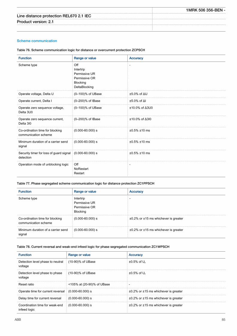
Scheme communication
Table 76. Scheme communication logic for distance or overcurrent protection ZCPSCH
Function Range or value Accuracy
Scheme type OffIntertripPermissive URPermissive ORBlockingDeltaBlocking
-
Operate voltage, Delta U (0–100)% of UBase ±5.0% of ΔU
Operate current, Delta I (0–200)% of IBase ±5.0% of ΔI
Operate zero sequence voltage,Delta 3U0
(0–100)% of UBase ±10.0% of Δ3U0
Operate zero sequence current,Delta 3I0
(0–200)% of IBase ±10.0% of Δ3I0
Co-ordination time for blockingcommunication scheme
(0.000-60.000) s ±0.5% ±10 ms
Minimum duration of a carrier sendsignal
(0.000-60.000) s ±0.5% ±10 ms
Security timer for loss of guard signaldetection
(0.000-60.000) s ±0.5% ±10 ms
Operation mode of unblocking logic OffNoRestartRestart
-
Table 77. Phase segregated scheme communication logic for distance protection ZC1PPSCH
Function Range or value Accuracy
Scheme type IntertripPermissive URPermissive ORBlocking
-
Co-ordination time for blockingcommunication scheme
(0.000-60.000) s ±0.2% or ±15 ms whichever is greater
Minimum duration of a carrier sendsignal
(0.000-60.000) s ±0.2% or ±15 ms whichever is greater
Table 78. Current reversal and weak-end infeed logic for phase segregated communication ZC1WPSCH
Function Range or value Accuracy
Detection level phase to neutralvoltage
(10-90)% of UBase ±0.5% of Ur
Detection level phase to phasevoltage
(10-90)% of UBase ±0.5% of Ur
Reset ratio <105% at (20-90)% of UBase -
Operate time for current reversal (0.000-60.000) s ±0.2% or ±15 ms whichever is greater
Delay time for current reversal (0.000-60.000) s ±0.2% or ±15 ms whichever is greater
Coordination time for weak-endinfeed logic
(0.000-60.000) s ±0.2% or ±15 ms whichever is greater
1MRK 506 356-BEN -Line distance protection REL670 2.1 IEC Product version: 2.1
ABB 85
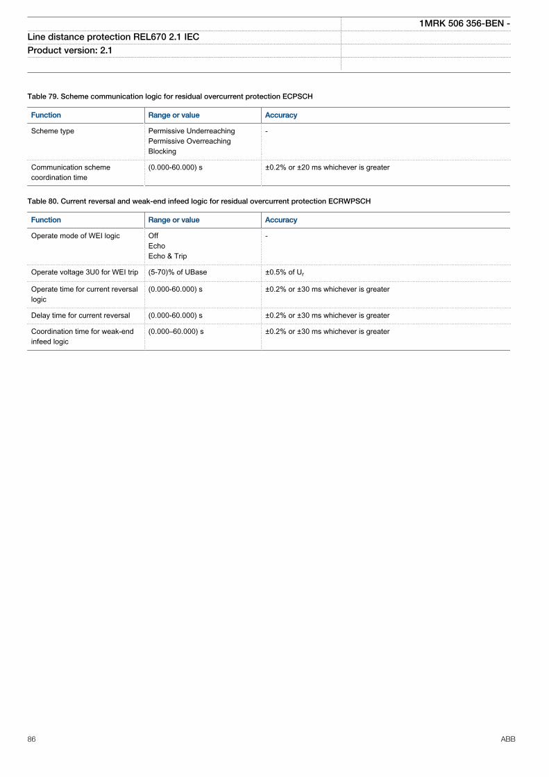
Table 79. Scheme communication logic for residual overcurrent protection ECPSCH
Function Range or value Accuracy
Scheme type Permissive UnderreachingPermissive OverreachingBlocking
-
Communication schemecoordination time
(0.000-60.000) s ±0.2% or ±20 ms whichever is greater
Table 80. Current reversal and weak-end infeed logic for residual overcurrent protection ECRWPSCH
Function Range or value Accuracy
Operate mode of WEI logic OffEchoEcho & Trip
-
Operate voltage 3U0 for WEI trip (5-70)% of UBase ±0.5% of Ur
Operate time for current reversallogic
(0.000-60.000) s ±0.2% or ±30 ms whichever is greater
Delay time for current reversal (0.000-60.000) s ±0.2% or ±30 ms whichever is greater
Coordination time for weak-endinfeed logic
(0.000–60.000) s ±0.2% or ±30 ms whichever is greater
1MRK 506 356-BEN -Line distance protection REL670 2.1 IEC Product version: 2.1
86 ABB
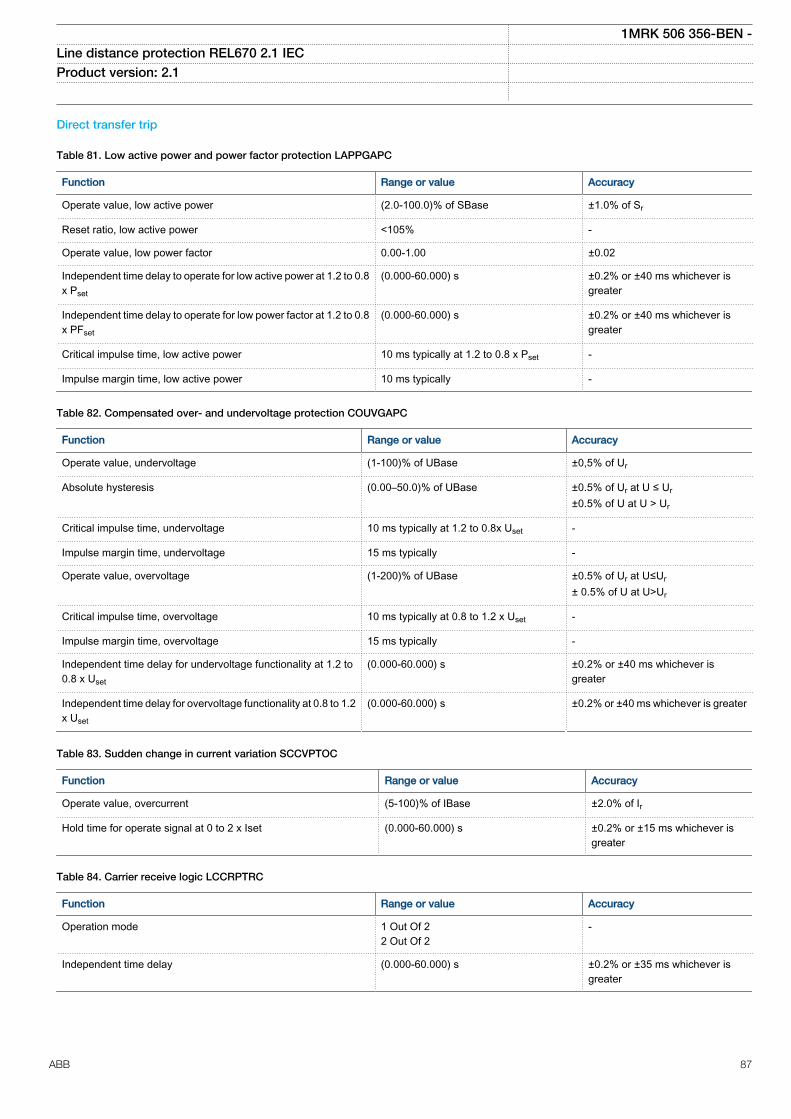
Direct transfer trip
Table 81. Low active power and power factor protection LAPPGAPC
Function Range or value Accuracy
Operate value, low active power (2.0-100.0)% of SBase ±1.0% of Sr
Reset ratio, low active power <105% -
Operate value, low power factor 0.00-1.00 ±0.02
Independent time delay to operate for low active power at 1.2 to 0.8x Pset
(0.000-60.000) s ±0.2% or ±40 ms whichever isgreater
Independent time delay to operate for low power factor at 1.2 to 0.8x PFset
(0.000-60.000) s ±0.2% or ±40 ms whichever isgreater
Critical impulse time, low active power 10 ms typically at 1.2 to 0.8 x Pset -
Impulse margin time, low active power 10 ms typically -
Table 82. Compensated over- and undervoltage protection COUVGAPC
Function Range or value Accuracy
Operate value, undervoltage (1-100)% of UBase ±0,5% of Ur
Absolute hysteresis (0.00–50.0)% of UBase ±0.5% of Ur at U ≤ Ur±0.5% of U at U > Ur
Critical impulse time, undervoltage 10 ms typically at 1.2 to 0.8x Uset -
Impulse margin time, undervoltage 15 ms typically -
Operate value, overvoltage (1-200)% of UBase ±0.5% of Ur at U≤Ur± 0.5% of U at U>Ur
Critical impulse time, overvoltage 10 ms typically at 0.8 to 1.2 x Uset -
Impulse margin time, overvoltage 15 ms typically -
Independent time delay for undervoltage functionality at 1.2 to0.8 x Uset
(0.000-60.000) s ±0.2% or ±40 ms whichever isgreater
Independent time delay for overvoltage functionality at 0.8 to 1.2x Uset
(0.000-60.000) s ±0.2% or ±40 ms whichever is greater
Table 83. Sudden change in current variation SCCVPTOC
Function Range or value Accuracy
Operate value, overcurrent (5-100)% of IBase ±2.0% of Ir
Hold time for operate signal at 0 to 2 x Iset (0.000-60.000) s ±0.2% or ±15 ms whichever isgreater
Table 84. Carrier receive logic LCCRPTRC
Function Range or value Accuracy
Operation mode 1 Out Of 22 Out Of 2
-
Independent time delay (0.000-60.000) s ±0.2% or ±35 ms whichever isgreater
1MRK 506 356-BEN -Line distance protection REL670 2.1 IEC Product version: 2.1
ABB 87
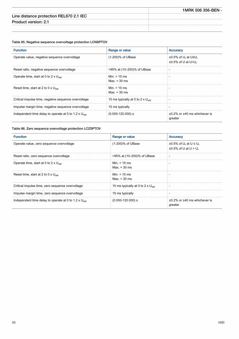
Table 85. Negative sequence overvoltage protection LCNSPTOV
Function Range or value Accuracy
Operate value, negative sequence overvoltage (1-200)% of UBase ±0.5% of Ur at U≤Ur±0.5% of U at U>Ur
Reset ratio, negative sequence overvoltage >95% at (10–200)% of UBase -
Operate time, start at 0 to 2 x Uset Min. = 15 msMax. = 30 ms
-
Reset time, start at 2 to 0 x Uset Min. = 15 msMax. = 30 ms
-
Critical impulse time, negative sequence overvoltage 10 ms typically at 0 to 2 x Uset -
Impulse margin time, negative sequence overvoltage 15 ms typically -
Independent time delay to operate at 0 to 1.2 x Uset (0.000-120.000) s ±0.2% or ±40 ms whichever isgreater
Table 86. Zero sequence overvoltage protection LCZSPTOV
Function Range or value Accuracy
Operate value, zero sequence overvoltage (1-200)% of UBase ±0.5% of Ur at U ≤ Ur±0.5% of U at U > Ur
Reset ratio, zero sequence overvoltage >95% at (10–200)% of UBase -
Operate time, start at 0 to 2 x Uset Min. = 15 msMax. = 30 ms
-
Reset time, start at 2 to 0 x Uset Min. = 15 msMax. = 30 ms
-
Critical impulse time, zero sequence overvoltage 10 ms typically at 0 to 2 x Uset -
Impulse margin time, zero sequence overvoltage 15 ms typically -
Independent time delay to operate at 0 to 1.2 x Uset (0.000-120.000) s ±0.2% or ±40 ms whichever isgreater
1MRK 506 356-BEN -Line distance protection REL670 2.1 IEC Product version: 2.1
88 ABB
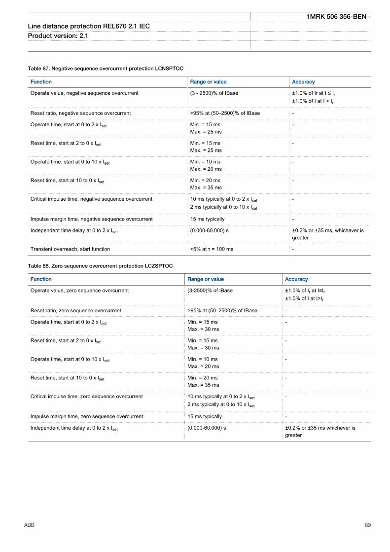
Table 87. Negative sequence overcurrent protection LCNSPTOC
Function Range or value Accuracy
Operate value, negative sequence overcurrent (3 - 2500)% of IBase ±1.0% of Ir at I ≤ Ir±1.0% of I at I > Ir
Reset ratio, negative sequence overcurrent >95% at (50–2500)% of IBase -
Operate time, start at 0 to 2 x Iset Min. = 15 msMax. = 25 ms
-
Reset time, start at 2 to 0 x Iset Min. = 15 msMax. = 25 ms
-
Operate time, start at 0 to 10 x Iset Min. = 10 msMax. = 20 ms
-
Reset time, start at 10 to 0 x Iset Min. = 20 msMax. = 35 ms
-
Critical impulse time, negative sequence overcurrent 10 ms typically at 0 to 2 x Iset2 ms typically at 0 to 10 x Iset
-
Impulse margin time, negative sequence overcurrent 15 ms typically -
Independent time delay at 0 to 2 x Iset (0.000-60.000) s ±0.2% or ±35 ms, whichever isgreater
Transient overreach, start function <5% at τ = 100 ms -
Table 88. Zero sequence overcurrent protection LCZSPTOC
Function Range or value Accuracy
Operate value, zero sequence overcurrent (3-2500)% of IBase ±1.0% of Ir at I≤Ir±1.0% of I at I>Ir
Reset ratio, zero sequence overcurrent >95% at (50–2500)% of IBase -
Operate time, start at 0 to 2 x Iset Min. = 15 msMax. = 30 ms
-
Reset time, start at 2 to 0 x Iset Min. = 15 msMax. = 30 ms
-
Operate time, start at 0 to 10 x Iset Min. = 10 msMax. = 20 ms
-
Reset time, start at 10 to 0 x Iset Min. = 20 msMax. = 35 ms
-
Critical impulse time, zero sequence overcurrent 10 ms typically at 0 to 2 x Iset2 ms typically at 0 to 10 x Iset
-
Impulse margin time, zero sequence overcurrent 15 ms typically -
Independent time delay at 0 to 2 x Iset (0.000-60.000) s ±0.2% or ±35 ms whichever isgreater
1MRK 506 356-BEN -Line distance protection REL670 2.1 IEC Product version: 2.1
ABB 89
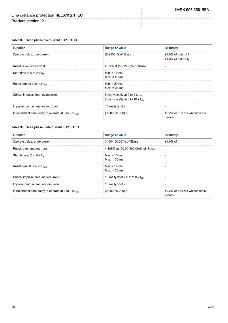
Table 89. Three phase overcurrent LCP3PTOC
Function Range or value Accuracy
Operate value, overcurrent (5-2500)% of IBase ±1.0% of Ir at I ≤ Ir±1.0% of I at I > Ir
Reset ratio, overcurrent > 95% at (50-2500)% of IBase -
Start time at 0 to 2 x Iset Min. = 10 msMax. = 25 ms
-
Reset time at 2 to 0 x Iset Min. = 20 msMax. = 35 ms
-
Critical impulse time, overcurrent 5 ms typically at 0 to 2 x Iset2 ms typically at 0 to 10 x Iset
-
Impulse margin time, overcurrent 10 ms typically -
Independent time delay to operate at 0 to 2 x Iset (0.000-60.000) s ±0.2% or ±30 ms whichever isgreater
Table 90. Three phase undercurrent LCP3PTUC
Function Range or value Accuracy
Operate value, undercurrent (1.00-100.00)% of IBase ±1.0% of Ir
Reset ratio, undercurrent < 105% at (50.00-100.00)% of IBase -
Start time at 2 to 0 x Iset Min. = 15 msMax. = 30 ms
-
Reset time at 0 to 2 x Iset Min. = 10 msMax. = 25 ms
-
Critical impulse time, undercurrent 10 ms typically at 2 to 0 x Iset -
Impulse margin time, undercurrent 10 ms typically -
Independent time delay to operate at 2 to 0 x Iset (0.000-60.000) s ±0.2% or ±45 ms whichever isgreater
1MRK 506 356-BEN -Line distance protection REL670 2.1 IEC Product version: 2.1
90 ABB
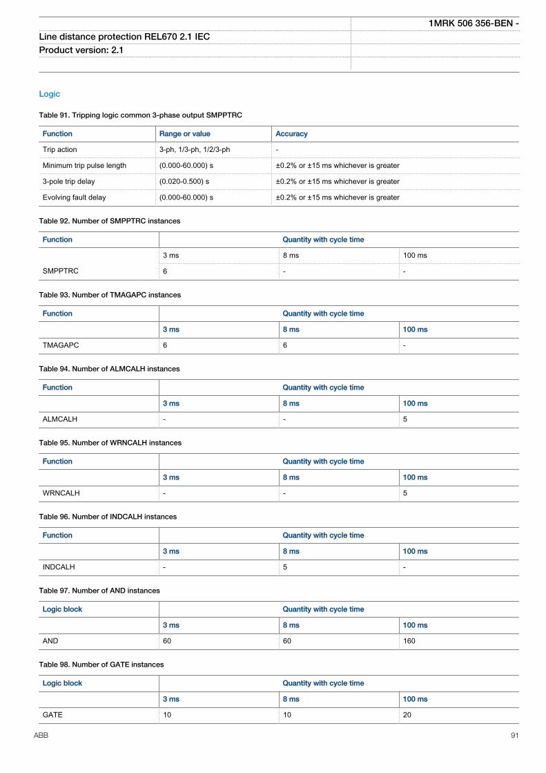
Logic
Table 91. Tripping logic common 3-phase output SMPPTRC
Function Range or value Accuracy
Trip action 3-ph, 1/3-ph, 1/2/3-ph -
Minimum trip pulse length (0.000-60.000) s ±0.2% or ±15 ms whichever is greater
3-pole trip delay (0.020-0.500) s ±0.2% or ±15 ms whichever is greater
Evolving fault delay (0.000-60.000) s ±0.2% or ±15 ms whichever is greater
Table 92. Number of SMPPTRC instances
Function Quantity with cycle time
3 ms 8 ms 100 ms
SMPPTRC 6 - -
Table 93. Number of TMAGAPC instances
Function Quantity with cycle time
3 ms 8 ms 100 ms
TMAGAPC 6 6 -
Table 94. Number of ALMCALH instances
Function Quantity with cycle time
3 ms 8 ms 100 ms
ALMCALH - - 5
Table 95. Number of WRNCALH instances
Function Quantity with cycle time
3 ms 8 ms 100 ms
WRNCALH - - 5
Table 96. Number of INDCALH instances
Function Quantity with cycle time
3 ms 8 ms 100 ms
INDCALH - 5 -
Table 97. Number of AND instances
Logic block Quantity with cycle time
3 ms 8 ms 100 ms
AND 60 60 160
Table 98. Number of GATE instances
Logic block Quantity with cycle time
3 ms 8 ms 100 ms
GATE 10 10 20
1MRK 506 356-BEN -Line distance protection REL670 2.1 IEC Product version: 2.1
ABB 91
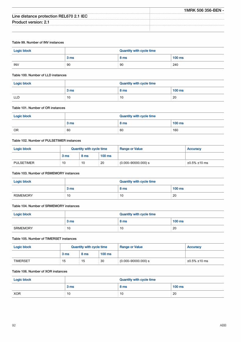
Table 99. Number of INV instances
Logic block Quantity with cycle time
3 ms 8 ms 100 ms
INV 90 90 240
Table 100. Number of LLD instances
Logic block Quantity with cycle time
3 ms 8 ms 100 ms
LLD 10 10 20
Table 101. Number of OR instances
Logic block Quantity with cycle time
3 ms 8 ms 100 ms
OR 60 60 160
Table 102. Number of PULSETIMER instances
Logic block Quantity with cycle time Range or Value Accuracy
3 ms 8 ms 100 ms
PULSETIMER 10 10 20 (0.000–90000.000) s ±0.5% ±10 ms
Table 103. Number of RSMEMORY instances
Logic block Quantity with cycle time
3 ms 8 ms 100 ms
RSMEMORY 10 10 20
Table 104. Number of SRMEMORY instances
Logic block Quantity with cycle time
3 ms 8 ms 100 ms
SRMEMORY 10 10 20
Table 105. Number of TIMERSET instances
Logic block Quantity with cycle time Range or Value Accuracy
3 ms 8 ms 100 ms
TIMERSET 15 15 30 (0.000–90000.000) s ±0.5% ±10 ms
Table 106. Number of XOR instances
Logic block Quantity with cycle time
3 ms 8 ms 100 ms
XOR 10 10 20
1MRK 506 356-BEN -Line distance protection REL670 2.1 IEC Product version: 2.1
92 ABB
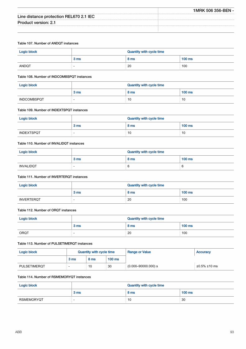
Table 107. Number of ANDQT instances
Logic block Quantity with cycle time
3 ms 8 ms 100 ms
ANDQT - 20 100
Table 108. Number of INDCOMBSPQT instances
Logic block Quantity with cycle time
3 ms 8 ms 100 ms
INDCOMBSPQT - 10 10
Table 109. Number of INDEXTSPQT instances
Logic block Quantity with cycle time
3 ms 8 ms 100 ms
INDEXTSPQT - 10 10
Table 110. Number of INVALIDQT instances
Logic block Quantity with cycle time
3 ms 8 ms 100 ms
INVALIDQT - 6 6
Table 111. Number of INVERTERQT instances
Logic block Quantity with cycle time
3 ms 8 ms 100 ms
INVERTERQT - 20 100
Table 112. Number of ORQT instances
Logic block Quantity with cycle time
3 ms 8 ms 100 ms
ORQT - 20 100
Table 113. Number of PULSETIMERQT instances
Logic block Quantity with cycle time Range or Value Accuracy
3 ms 8 ms 100 ms
PULSETIMERQT - 10 30 (0.000–90000.000) s ±0.5% ±10 ms
Table 114. Number of RSMEMORYQT instances
Logic block Quantity with cycle time
3 ms 8 ms 100 ms
RSMEMORYQT - 10 30
1MRK 506 356-BEN -Line distance protection REL670 2.1 IEC Product version: 2.1
ABB 93
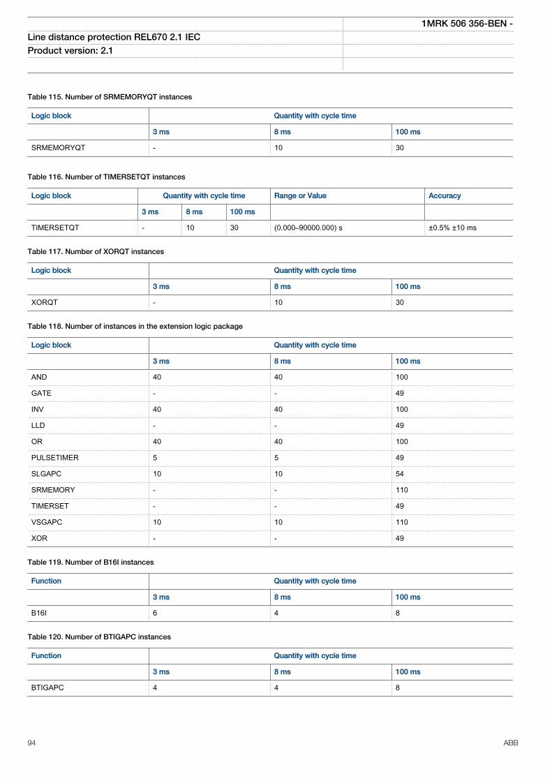
Table 115. Number of SRMEMORYQT instances
Logic block Quantity with cycle time
3 ms 8 ms 100 ms
SRMEMORYQT - 10 30
Table 116. Number of TIMERSETQT instances
Logic block Quantity with cycle time Range or Value Accuracy
3 ms 8 ms 100 ms
TIMERSETQT - 10 30 (0.000–90000.000) s ±0.5% ±10 ms
Table 117. Number of XORQT instances
Logic block Quantity with cycle time
3 ms 8 ms 100 ms
XORQT - 10 30
Table 118. Number of instances in the extension logic package
Logic block Quantity with cycle time
3 ms 8 ms 100 ms
AND 40 40 100
GATE - - 49
INV 40 40 100
LLD - - 49
OR 40 40 100
PULSETIMER 5 5 49
SLGAPC 10 10 54
SRMEMORY - - 110
TIMERSET - - 49
VSGAPC 10 10 110
XOR - - 49
Table 119. Number of B16I instances
Function Quantity with cycle time
3 ms 8 ms 100 ms
B16I 6 4 8
Table 120. Number of BTIGAPC instances
Function Quantity with cycle time
3 ms 8 ms 100 ms
BTIGAPC 4 4 8
1MRK 506 356-BEN -Line distance protection REL670 2.1 IEC Product version: 2.1
94 ABB
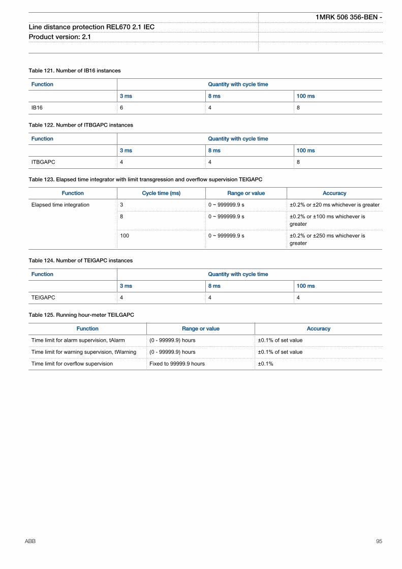
Table 121. Number of IB16 instances
Function Quantity with cycle time
3 ms 8 ms 100 ms
IB16 6 4 8
Table 122. Number of ITBGAPC instances
Function Quantity with cycle time
3 ms 8 ms 100 ms
ITBGAPC 4 4 8
Table 123. Elapsed time integrator with limit transgression and overflow supervision TEIGAPC
Function Cycle time (ms) Range or value Accuracy
Elapsed time integration 3 0 ~ 999999.9 s ±0.2% or ±20 ms whichever is greater
8 0 ~ 999999.9 s ±0.2% or ±100 ms whichever isgreater
100 0 ~ 999999.9 s ±0.2% or ±250 ms whichever isgreater
Table 124. Number of TEIGAPC instances
Function Quantity with cycle time
3 ms 8 ms 100 ms
TEIGAPC 4 4 4
Table 125. Running hour-meter TEILGAPC
Function Range or value Accuracy
Time limit for alarm supervision, tAlarm (0 - 99999.9) hours ±0.1% of set value
Time limit for warning supervision, tWarning (0 - 99999.9) hours ±0.1% of set value
Time limit for overflow supervision Fixed to 99999.9 hours ±0.1%
1MRK 506 356-BEN -Line distance protection REL670 2.1 IEC Product version: 2.1
ABB 95
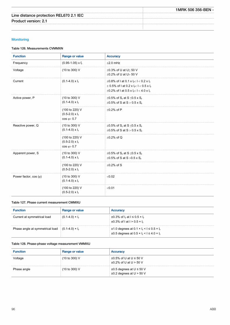
Monitoring
Table 126. Measurements CVMMXN
Function Range or value Accuracy
Frequency (0.95-1.05) x fr ±2.0 mHz
Voltage (10 to 300) V ±0.3% of U at U≤ 50 V±0.2% of U at U> 50 V
Current (0.1-4.0) x Ir ±0.8% of I at 0.1 x Ir< I < 0.2 x Ir± 0.5% of I at 0.2 x Ir< I < 0.5 x Ir±0.2% of I at 0.5 x Ir< I < 4.0 x Ir
Active power, P (10 to 300) V(0.1-4.0) x Ir
±0.5% of Sr at S ≤0.5 x Sr
±0.5% of S at S > 0.5 x Sr
(100 to 220) V(0.5-2.0) x Ircos φ< 0.7
±0.2% of P
Reactive power, Q (10 to 300) V(0.1-4.0) x Ir
±0.5% of Sr at S ≤0.5 x Sr
±0.5% of S at S > 0.5 x Sr
(100 to 220) V(0.5-2.0) x Ircos φ> 0.7
±0.2% of Q
Apparent power, S (10 to 300) V(0.1-4.0) x Ir
±0.5% of Sr at S ≤0.5 x Sr
±0.5% of S at S >0.5 x Sr
(100 to 220) V(0.5-2.0) x Ir
±0.2% of S
Power factor, cos (φ) (10 to 300) V(0.1-4.0) x Ir
<0.02
(100 to 220) V(0.5-2.0) x Ir
<0.01
Table 127. Phase current measurement CMMXU
Function Range or value Accuracy
Current at symmetrical load (0.1-4.0) × Ir ±0.3% of Ir at I ≤ 0.5 × Ir±0.3% of I at I > 0.5 × Ir
Phase angle at symmetrical load (0.1-4.0) × Ir ±1.0 degrees at 0.1 × Ir < I ≤ 0.5 × Ir±0.5 degrees at 0.5 × Ir < I ≤ 4.0 × Ir
Table 128. Phase-phase voltage measurement VMMXU
Function Range or value Accuracy
Voltage (10 to 300) V ±0.5% of U at U ≤ 50 V±0.2% of U at U > 50 V
Phase angle (10 to 300) V ±0.5 degrees at U ≤ 50 V±0.2 degrees at U > 50 V
1MRK 506 356-BEN -Line distance protection REL670 2.1 IEC Product version: 2.1
96 ABB
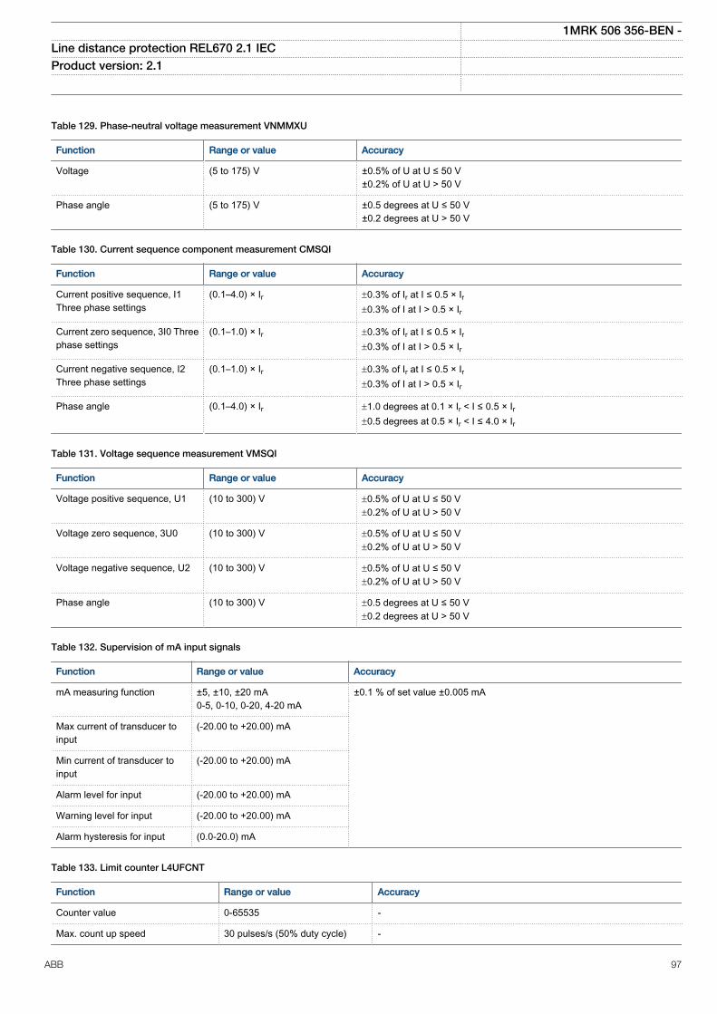
Table 129. Phase-neutral voltage measurement VNMMXU
Function Range or value Accuracy
Voltage (5 to 175) V ±0.5% of U at U ≤ 50 V±0.2% of U at U > 50 V
Phase angle (5 to 175) V ±0.5 degrees at U ≤ 50 V±0.2 degrees at U > 50 V
Table 130. Current sequence component measurement CMSQI
Function Range or value Accuracy
Current positive sequence, I1Three phase settings
(0.1–4.0) × Ir ±0.3% of Ir at I ≤ 0.5 × Ir±0.3% of I at I > 0.5 × Ir
Current zero sequence, 3I0 Threephase settings
(0.1–1.0) × Ir ±0.3% of Ir at I ≤ 0.5 × Ir±0.3% of I at I > 0.5 × Ir
Current negative sequence, I2Three phase settings
(0.1–1.0) × Ir ±0.3% of Ir at I ≤ 0.5 × Ir±0.3% of I at I > 0.5 × Ir
Phase angle (0.1–4.0) × Ir ±1.0 degrees at 0.1 × Ir < I ≤ 0.5 × Ir±0.5 degrees at 0.5 × Ir < I ≤ 4.0 × Ir
Table 131. Voltage sequence measurement VMSQI
Function Range or value Accuracy
Voltage positive sequence, U1 (10 to 300) V ±0.5% of U at U ≤ 50 V±0.2% of U at U > 50 V
Voltage zero sequence, 3U0 (10 to 300) V ±0.5% of U at U ≤ 50 V±0.2% of U at U > 50 V
Voltage negative sequence, U2 (10 to 300) V ±0.5% of U at U ≤ 50 V±0.2% of U at U > 50 V
Phase angle (10 to 300) V ±0.5 degrees at U ≤ 50 V±0.2 degrees at U > 50 V
Table 132. Supervision of mA input signals
Function Range or value Accuracy
mA measuring function ±5, ±10, ±20 mA0-5, 0-10, 0-20, 4-20 mA
±0.1 % of set value ±0.005 mA
Max current of transducer toinput
(-20.00 to +20.00) mA
Min current of transducer toinput
(-20.00 to +20.00) mA
Alarm level for input (-20.00 to +20.00) mA
Warning level for input (-20.00 to +20.00) mA
Alarm hysteresis for input (0.0-20.0) mA
Table 133. Limit counter L4UFCNT
Function Range or value Accuracy
Counter value 0-65535 -
Max. count up speed 30 pulses/s (50% duty cycle) -
1MRK 506 356-BEN -Line distance protection REL670 2.1 IEC Product version: 2.1
ABB 97
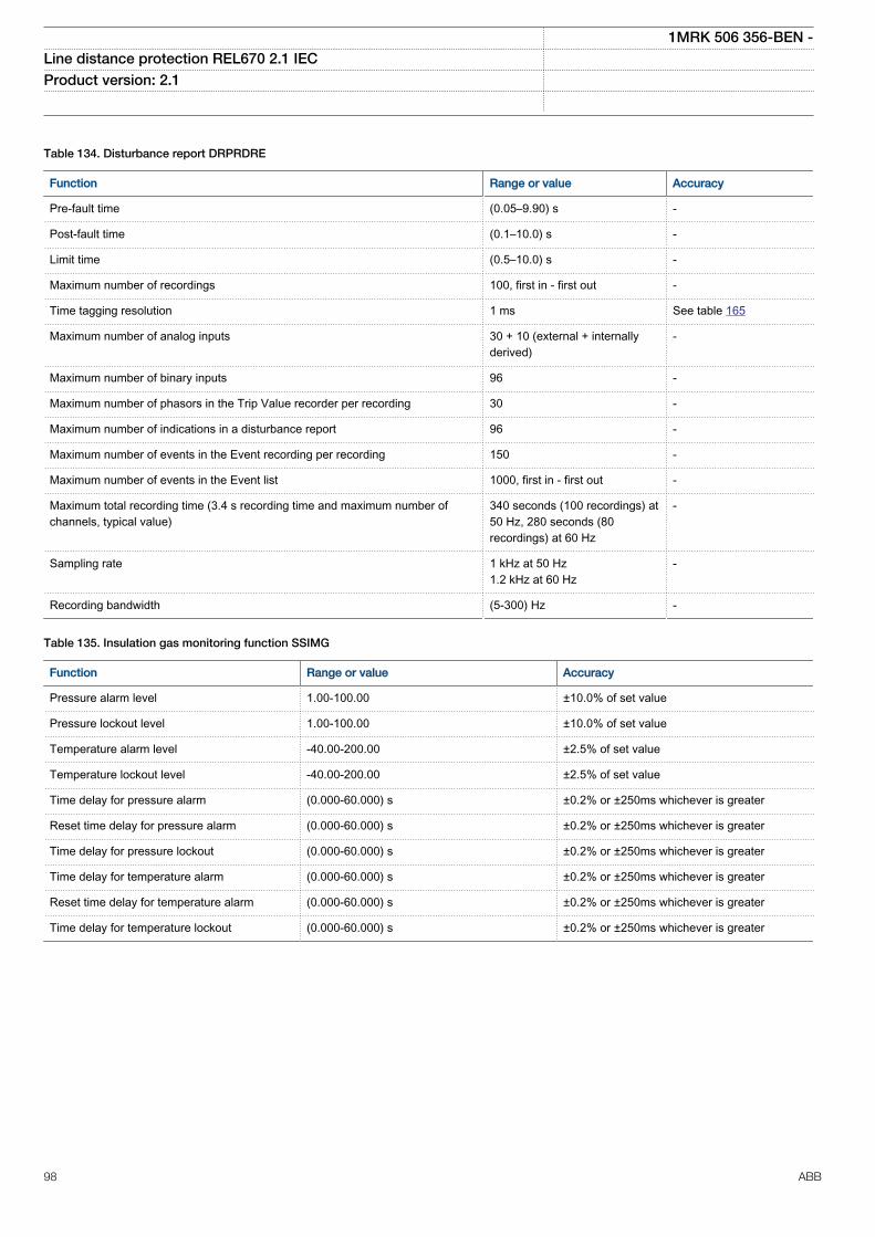
Table 134. Disturbance report DRPRDRE
Function Range or value Accuracy
Pre-fault time (0.05–9.90) s -
Post-fault time (0.1–10.0) s -
Limit time (0.5–10.0) s -
Maximum number of recordings 100, first in - first out -
Time tagging resolution 1 ms See table 165
Maximum number of analog inputs 30 + 10 (external + internallyderived)
-
Maximum number of binary inputs 96 -
Maximum number of phasors in the Trip Value recorder per recording 30 -
Maximum number of indications in a disturbance report 96 -
Maximum number of events in the Event recording per recording 150 -
Maximum number of events in the Event list 1000, first in - first out -
Maximum total recording time (3.4 s recording time and maximum number ofchannels, typical value)
340 seconds (100 recordings) at50 Hz, 280 seconds (80recordings) at 60 Hz
-
Sampling rate 1 kHz at 50 Hz1.2 kHz at 60 Hz
-
Recording bandwidth (5-300) Hz -
Table 135. Insulation gas monitoring function SSIMG
Function Range or value Accuracy
Pressure alarm level 1.00-100.00 ±10.0% of set value
Pressure lockout level 1.00-100.00 ±10.0% of set value
Temperature alarm level -40.00-200.00 ±2.5% of set value
Temperature lockout level -40.00-200.00 ±2.5% of set value
Time delay for pressure alarm (0.000-60.000) s ±0.2% or ±250ms whichever is greater
Reset time delay for pressure alarm (0.000-60.000) s ±0.2% or ±250ms whichever is greater
Time delay for pressure lockout (0.000-60.000) s ±0.2% or ±250ms whichever is greater
Time delay for temperature alarm (0.000-60.000) s ±0.2% or ±250ms whichever is greater
Reset time delay for temperature alarm (0.000-60.000) s ±0.2% or ±250ms whichever is greater
Time delay for temperature lockout (0.000-60.000) s ±0.2% or ±250ms whichever is greater
1MRK 506 356-BEN -Line distance protection REL670 2.1 IEC Product version: 2.1
98 ABB
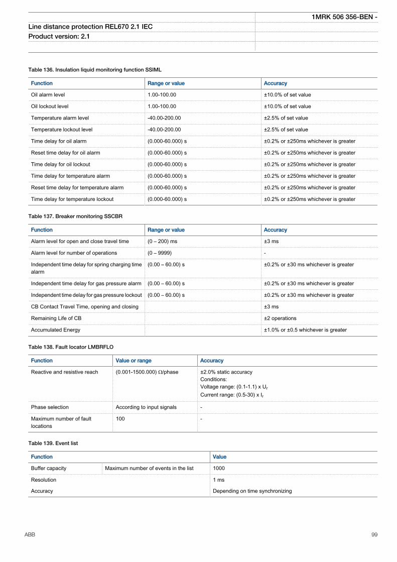
Table 136. Insulation liquid monitoring function SSIML
Function Range or value Accuracy
Oil alarm level 1.00-100.00 ±10.0% of set value
Oil lockout level 1.00-100.00 ±10.0% of set value
Temperature alarm level -40.00-200.00 ±2.5% of set value
Temperature lockout level -40.00-200.00 ±2.5% of set value
Time delay for oil alarm (0.000-60.000) s ±0.2% or ±250ms whichever is greater
Reset time delay for oil alarm (0.000-60.000) s ±0.2% or ±250ms whichever is greater
Time delay for oil lockout (0.000-60.000) s ±0.2% or ±250ms whichever is greater
Time delay for temperature alarm (0.000-60.000) s ±0.2% or ±250ms whichever is greater
Reset time delay for temperature alarm (0.000-60.000) s ±0.2% or ±250ms whichever is greater
Time delay for temperature lockout (0.000-60.000) s ±0.2% or ±250ms whichever is greater
Table 137. Breaker monitoring SSCBR
Function Range or value Accuracy
Alarm level for open and close travel time (0 – 200) ms ±3 ms
Alarm level for number of operations (0 – 9999) -
Independent time delay for spring charging timealarm
(0.00 – 60.00) s ±0.2% or ±30 ms whichever is greater
Independent time delay for gas pressure alarm (0.00 – 60.00) s ±0.2% or ±30 ms whichever is greater
Independent time delay for gas pressure lockout (0.00 – 60.00) s ±0.2% or ±30 ms whichever is greater
CB Contact Travel Time, opening and closing ±3 ms
Remaining Life of CB ±2 operations
Accumulated Energy ±1.0% or ±0.5 whichever is greater
Table 138. Fault locator LMBRFLO
Function Value or range Accuracy
Reactive and resistive reach (0.001-1500.000) Ω/phase ±2.0% static accuracyConditions:Voltage range: (0.1-1.1) x UrCurrent range: (0.5-30) x Ir
Phase selection According to input signals -
Maximum number of faultlocations
100 -
Table 139. Event list
Function Value
Buffer capacity Maximum number of events in the list 1000
Resolution 1 ms
Accuracy Depending on time synchronizing
1MRK 506 356-BEN -Line distance protection REL670 2.1 IEC Product version: 2.1
ABB 99
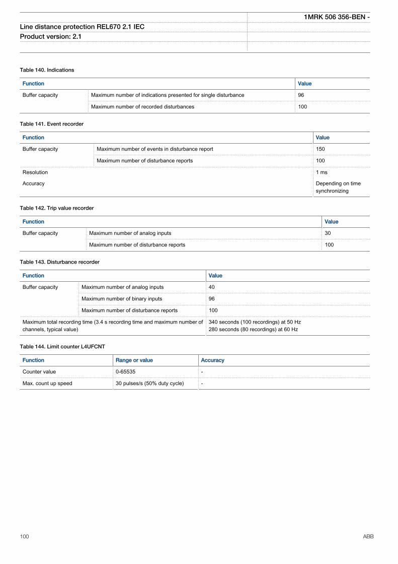
Table 140. Indications
Function Value
Buffer capacity Maximum number of indications presented for single disturbance 96
Maximum number of recorded disturbances 100
Table 141. Event recorder
Function Value
Buffer capacity Maximum number of events in disturbance report 150
Maximum number of disturbance reports 100
Resolution 1 ms
Accuracy Depending on timesynchronizing
Table 142. Trip value recorder
Function Value
Buffer capacity
Maximum number of analog inputs 30
Maximum number of disturbance reports 100
Table 143. Disturbance recorder
Function Value
Buffer capacity Maximum number of analog inputs 40
Maximum number of binary inputs 96
Maximum number of disturbance reports 100
Maximum total recording time (3.4 s recording time and maximum number ofchannels, typical value)
340 seconds (100 recordings) at 50 Hz280 seconds (80 recordings) at 60 Hz
Table 144. Limit counter L4UFCNT
Function Range or value Accuracy
Counter value 0-65535 -
Max. count up speed 30 pulses/s (50% duty cycle) -
1MRK 506 356-BEN -Line distance protection REL670 2.1 IEC Product version: 2.1
100 ABB
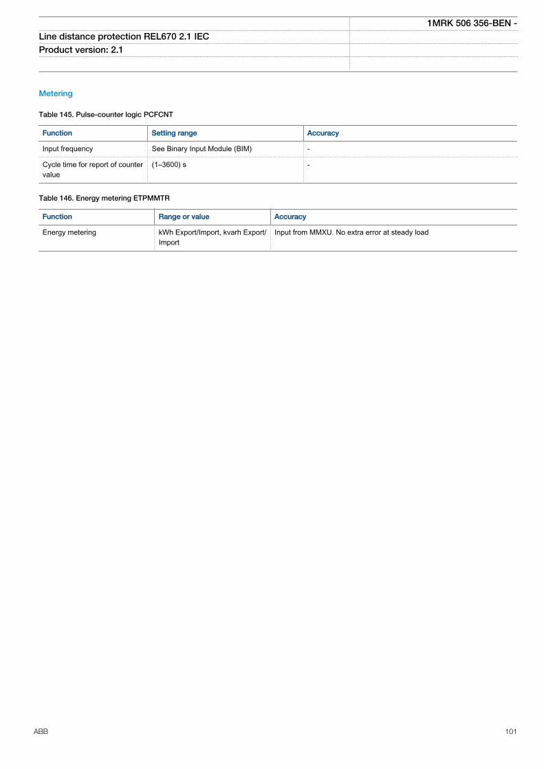
Metering
Table 145. Pulse-counter logic PCFCNT
Function Setting range Accuracy
Input frequency See Binary Input Module (BIM) -
Cycle time for report of countervalue
(1–3600) s -
Table 146. Energy metering ETPMMTR
Function Range or value Accuracy
Energy metering kWh Export/Import, kvarh Export/Import
Input from MMXU. No extra error at steady load
1MRK 506 356-BEN -Line distance protection REL670 2.1 IEC Product version: 2.1
ABB 101
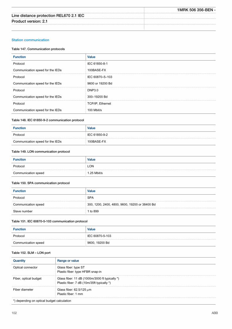
Station communication
Table 147. Communication protocols
Function Value
Protocol IEC 61850-8-1
Communication speed for the IEDs 100BASE-FX
Protocol IEC 60870–5–103
Communication speed for the IEDs 9600 or 19200 Bd
Protocol DNP3.0
Communication speed for the IEDs 300–19200 Bd
Protocol TCP/IP, Ethernet
Communication speed for the IEDs 100 Mbit/s
Table 148. IEC 61850-9-2 communication protocol
Function Value
Protocol IEC 61850-9-2
Communication speed for the IEDs 100BASE-FX
Table 149. LON communication protocol
Function Value
Protocol LON
Communication speed 1.25 Mbit/s
Table 150. SPA communication protocol
Function Value
Protocol SPA
Communication speed 300, 1200, 2400, 4800, 9600, 19200 or 38400 Bd
Slave number 1 to 899
Table 151. IEC 60870-5-103 communication protocol
Function Value
Protocol IEC 60870-5-103
Communication speed 9600, 19200 Bd
Table 152. SLM – LON port
Quantity Range or value
Optical connector Glass fiber: type STPlastic fiber: type HFBR snap-in
Fiber, optical budget Glass fiber: 11 dB (1000m/3000 ft typically *)Plastic fiber: 7 dB (10m/35ft typically *)
Fiber diameter Glass fiber: 62.5/125 mmPlastic fiber: 1 mm
*) depending on optical budget calculation
1MRK 506 356-BEN -Line distance protection REL670 2.1 IEC Product version: 2.1
102 ABB
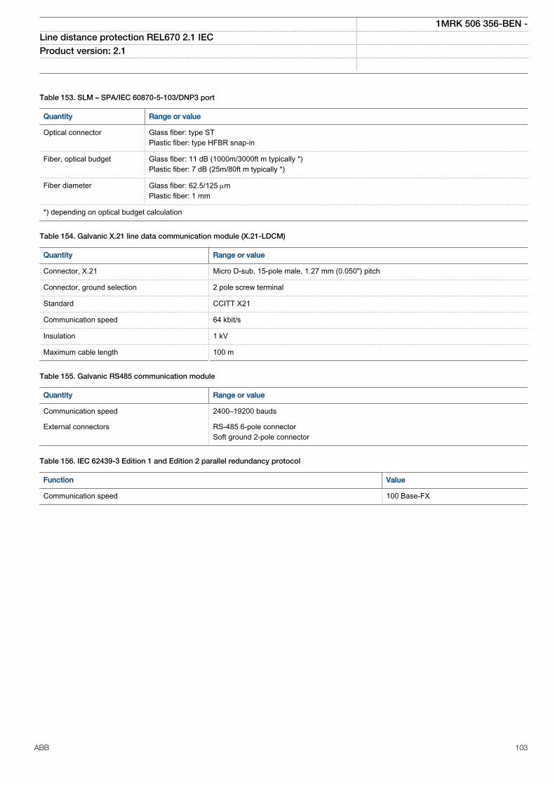
Table 153. SLM – SPA/IEC 60870-5-103/DNP3 port
Quantity Range or value
Optical connector Glass fiber: type STPlastic fiber: type HFBR snap-in
Fiber, optical budget Glass fiber: 11 dB (1000m/3000ft m typically *)Plastic fiber: 7 dB (25m/80ft m typically *)
Fiber diameter Glass fiber: 62.5/125 mmPlastic fiber: 1 mm
*) depending on optical budget calculation
Table 154. Galvanic X.21 line data communication module (X.21-LDCM)
Quantity Range or value
Connector, X.21 Micro D-sub, 15-pole male, 1.27 mm (0.050") pitch
Connector, ground selection 2 pole screw terminal
Standard CCITT X21
Communication speed 64 kbit/s
Insulation 1 kV
Maximum cable length 100 m
Table 155. Galvanic RS485 communication module
Quantity Range or value
Communication speed 2400–19200 bauds
External connectors RS-485 6-pole connectorSoft ground 2-pole connector
Table 156. IEC 62439-3 Edition 1 and Edition 2 parallel redundancy protocol
Function Value
Communication speed 100 Base-FX
1MRK 506 356-BEN -Line distance protection REL670 2.1 IEC Product version: 2.1
ABB 103
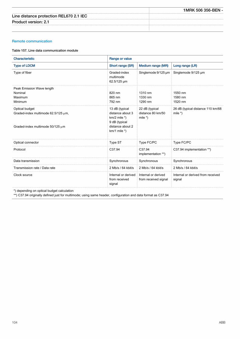
Remote communication
Table 157. Line data communication module
Characteristic Range or value
Type of LDCM Short range (SR) Medium range (MR) Long range (LR)
Type of fiber Graded-indexmultimode62.5/125 µm
Singlemode 9/125 µm Singlemode 9/125 µm
Peak Emission Wave lengthNominalMaximumMinimum
820 nm865 nm792 nm
1310 nm1330 nm1290 nm
1550 nm1580 nm1520 nm
Optical budgetGraded-index multimode 62.5/125 mm, Graded-index multimode 50/125 mm
13 dB (typicaldistance about 3km/2 mile *)9 dB (typicaldistance about 2km/1 mile *)
22 dB (typicaldistance 80 km/50mile *)
26 dB (typical distance 110 km/68mile *)
Optical connector Type ST Type FC/PC Type FC/PC
Protocol C37.94 C37.94implementation **)
C37.94 implementation **)
Data transmission Synchronous Synchronous Synchronous
Transmission rate / Data rate 2 Mb/s / 64 kbit/s 2 Mb/s / 64 kbit/s 2 Mb/s / 64 kbit/s
Clock source Internal or derivedfrom receivedsignal
Internal or derivedfrom received signal
Internal or derived from receivedsignal
*) depending on optical budget calculation**) C37.94 originally defined just for multimode; using same header, configuration and data format as C37.94
1MRK 506 356-BEN -Line distance protection REL670 2.1 IEC Product version: 2.1
104 ABB
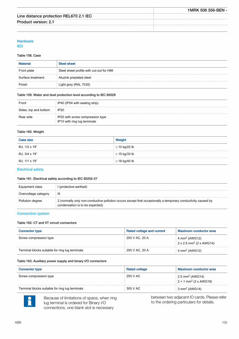
HardwareIED
Table 158. Case
Material Steel sheet
Front plate Steel sheet profile with cut-out for HMI
Surface treatment Aluzink preplated steel
Finish Light grey (RAL 7035)
Table 159. Water and dust protection level according to IEC 60529
Front IP40 (IP54 with sealing strip)
Sides, top and bottom IP20
Rear side IP20 with screw compression typeIP10 with ring lug terminals
Table 160. Weight
Case size Weight
6U, 1/2 x 19” £ 10 kg/22 lb
6U, 3/4 x 19” £ 15 kg/33 lb
6U, 1/1 x 19” £ 18 kg/40 lb
Electrical safety
Table 161. Electrical safety according to IEC 60255-27
Equipment class I (protective earthed)
Overvoltage category III
Pollution degree 2 (normally only non-conductive pollution occurs except that occasionally a temporary conductivity caused bycondensation is to be expected)
Connection system
Table 162. CT and VT circuit connectors
Connector type Rated voltage and current Maximum conductor area
Screw compression type 250 V AC, 20 A 4 mm2 (AWG12)2 x 2.5 mm2 (2 x AWG14)
Terminal blocks suitable for ring lug terminals 250 V AC, 20 A 4 mm2 (AWG12)
Table 163. Auxiliary power supply and binary I/O connectors
Connector type Rated voltage Maximum conductor area
Screw compression type 250 V AC 2.5 mm2 (AWG14)2 × 1 mm2 (2 x AWG18)
Terminal blocks suitable for ring lug terminals 300 V AC 3 mm2 (AWG14)
Because of limitations of space, when ringlug terminal is ordered for Binary I/Oconnections, one blank slot is necessary
between two adjacent IO cards. Please referto the ordering particulars for details.
1MRK 506 356-BEN -Line distance protection REL670 2.1 IEC Product version: 2.1
ABB 105
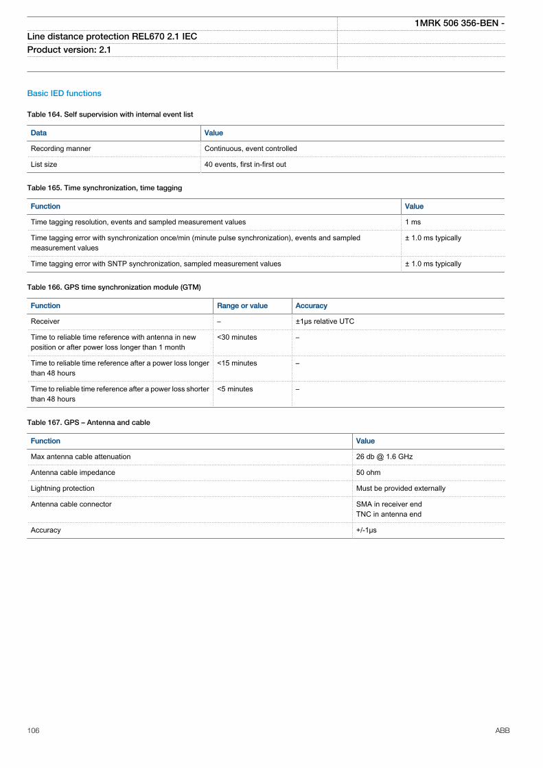
Basic IED functions
Table 164. Self supervision with internal event list
Data Value
Recording manner Continuous, event controlled
List size 40 events, first in-first out
Table 165. Time synchronization, time tagging
Function Value
Time tagging resolution, events and sampled measurement values 1 ms
Time tagging error with synchronization once/min (minute pulse synchronization), events and sampledmeasurement values
± 1.0 ms typically
Time tagging error with SNTP synchronization, sampled measurement values ± 1.0 ms typically
Table 166. GPS time synchronization module (GTM)
Function Range or value Accuracy
Receiver – ±1µs relative UTC
Time to reliable time reference with antenna in newposition or after power loss longer than 1 month
<30 minutes –
Time to reliable time reference after a power loss longerthan 48 hours
<15 minutes –
Time to reliable time reference after a power loss shorterthan 48 hours
<5 minutes –
Table 167. GPS – Antenna and cable
Function Value
Max antenna cable attenuation 26 db @ 1.6 GHz
Antenna cable impedance 50 ohm
Lightning protection Must be provided externally
Antenna cable connector SMA in receiver endTNC in antenna end
Accuracy +/-1μs
1MRK 506 356-BEN -Line distance protection REL670 2.1 IEC Product version: 2.1
106 ABB
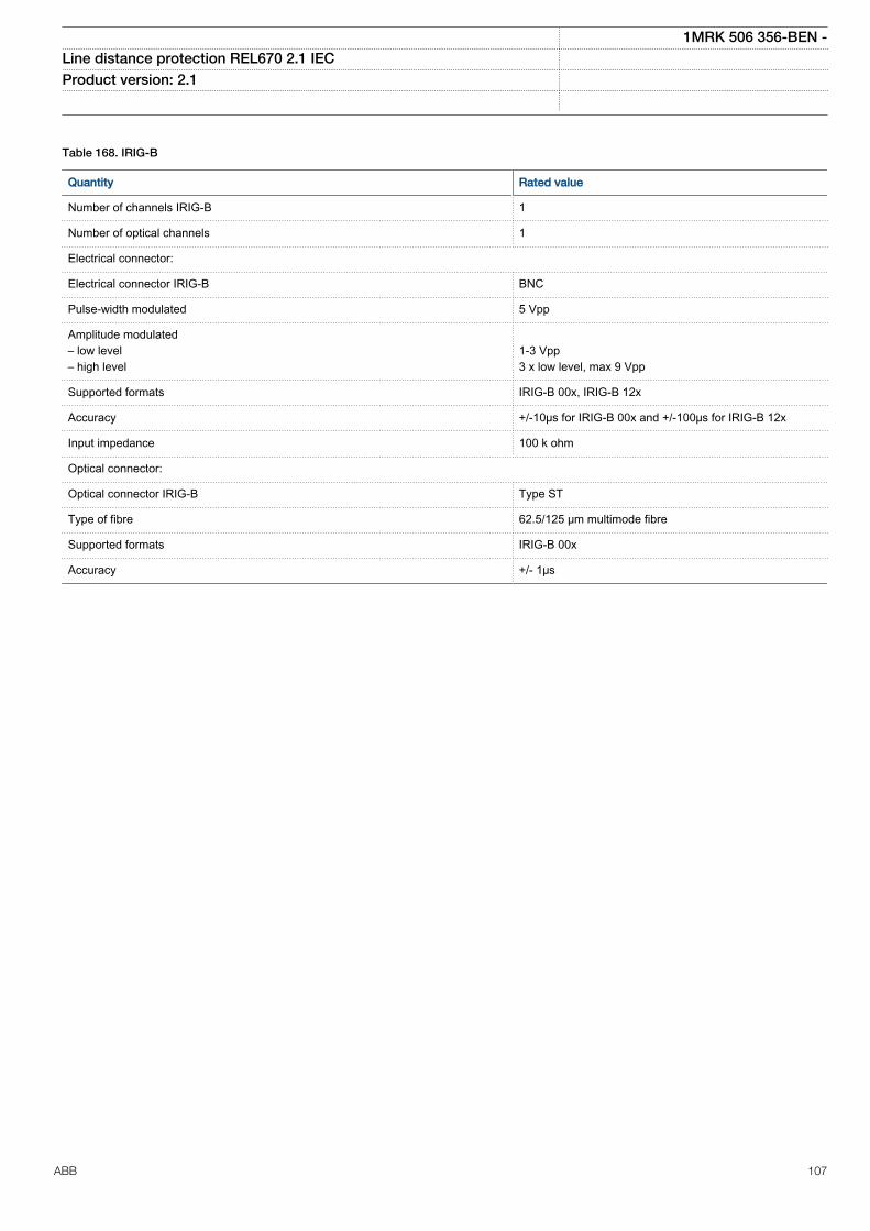
Table 168. IRIG-B
Quantity Rated value
Number of channels IRIG-B 1
Number of optical channels 1
Electrical connector:
Electrical connector IRIG-B BNC
Pulse-width modulated 5 Vpp
Amplitude modulated– low level– high level
1-3 Vpp3 x low level, max 9 Vpp
Supported formats IRIG-B 00x, IRIG-B 12x
Accuracy +/-10μs for IRIG-B 00x and +/-100μs for IRIG-B 12x
Input impedance 100 k ohm
Optical connector:
Optical connector IRIG-B Type ST
Type of fibre 62.5/125 μm multimode fibre
Supported formats IRIG-B 00x
Accuracy +/- 1μs
1MRK 506 356-BEN -Line distance protection REL670 2.1 IEC Product version: 2.1
ABB 107
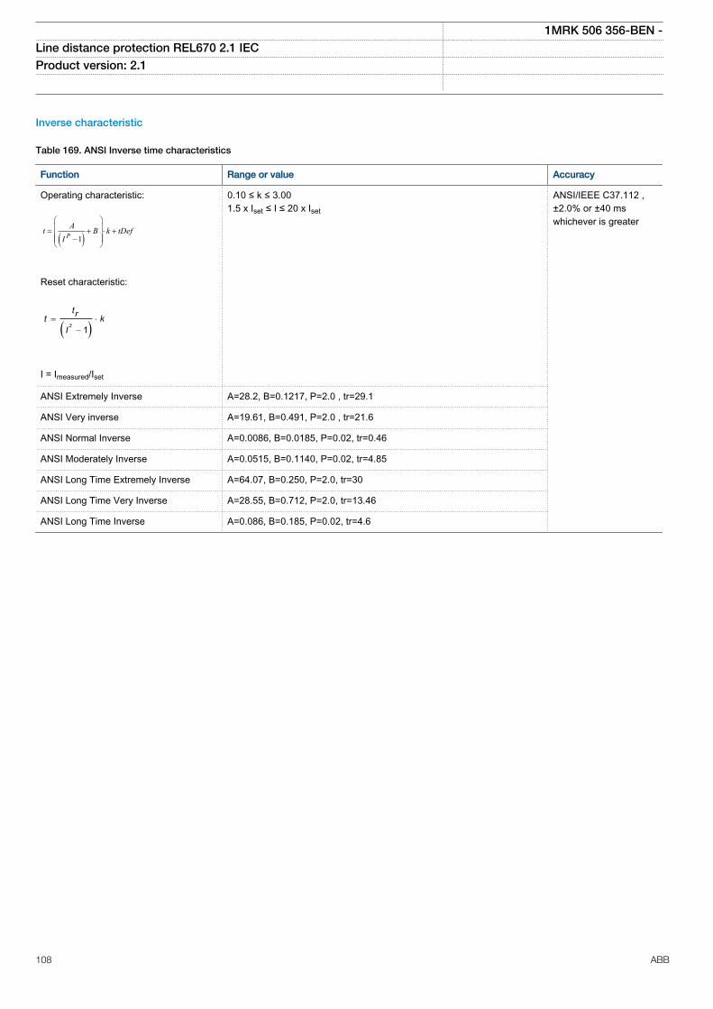
Inverse characteristic
Table 169. ANSI Inverse time characteristics
Function Range or value Accuracy
Operating characteristic:
( )1PAt B k tDef
I
æ öç ÷= + × +ç ÷ç - ÷è ø
EQUATION1249-SMALL V2 EN
Reset characteristic:
( )2 1= ×
-
trt kI
EQUATION1250-SMALL V1 EN
I = Imeasured/Iset
0.10 ≤ k ≤ 3.001.5 x Iset ≤ I ≤ 20 x Iset
ANSI/IEEE C37.112 ,±2.0% or ±40 mswhichever is greater
ANSI Extremely Inverse A=28.2, B=0.1217, P=2.0 , tr=29.1
ANSI Very inverse A=19.61, B=0.491, P=2.0 , tr=21.6
ANSI Normal Inverse A=0.0086, B=0.0185, P=0.02, tr=0.46
ANSI Moderately Inverse A=0.0515, B=0.1140, P=0.02, tr=4.85
ANSI Long Time Extremely Inverse A=64.07, B=0.250, P=2.0, tr=30
ANSI Long Time Very Inverse A=28.55, B=0.712, P=2.0, tr=13.46
ANSI Long Time Inverse A=0.086, B=0.185, P=0.02, tr=4.6
1MRK 506 356-BEN -Line distance protection REL670 2.1 IEC Product version: 2.1
108 ABB
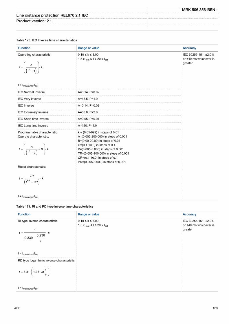
Table 170. IEC Inverse time characteristics
Function Range or value Accuracy
Operating characteristic:
( )1= ×
-
æ öç ÷ç ÷è ø
P
At k
I
EQUATION1251-SMALL V1 EN
I = Imeasured/Iset
0.10 ≤ k ≤ 3.001.5 x Iset ≤ I ≤ 20 x Iset
IEC 60255-151, ±2.0%or ±40 ms whichever isgreater
IEC Normal Inverse A=0.14, P=0.02
IEC Very inverse A=13.5, P=1.0
IEC Inverse A=0.14, P=0.02
IEC Extremely inverse A=80.0, P=2.0
IEC Short time inverse A=0.05, P=0.04
IEC Long time inverse A=120, P=1.0
Programmable characteristicOperate characteristic:
( )= + ×
-
æ öç ÷ç ÷è ø
P
At B k
I C
EQUATION1370-SMALL V1 EN
Reset characteristic:
( )= ×
-PR
TRt k
I CR
EQUATION1253-SMALL V1 EN
I = Imeasured/Iset
k = (0.05-999) in steps of 0.01A=(0.005-200.000) in steps of 0.001B=(0.00-20.00) in steps of 0.01C=(0.1-10.0) in steps of 0.1P=(0.005-3.000) in steps of 0.001TR=(0.005-100.000) in steps of 0.001CR=(0.1-10.0) in steps of 0.1PR=(0.005-3.000) in steps of 0.001
Table 171. RI and RD type inverse time characteristics
Function Range or value Accuracy
RI type inverse characteristic
1
0.2360.339
= ×
-
t k
IEQUATION1137-SMALL V1 EN
I = Imeasured/Iset
0.10 ≤ k ≤ 3.001.5 x Iset ≤ I ≤ 20 x Iset
IEC 60255-151, ±2.0%or ±40 ms whichever isgreater
RD type logarithmic inverse characteristic
5.8 1.35= - ×æ öç ÷è ø
tI
Ink
EQUATION1138-SMALL V1 EN
I = Imeasured/Iset
1MRK 506 356-BEN -Line distance protection REL670 2.1 IEC Product version: 2.1
ABB 109
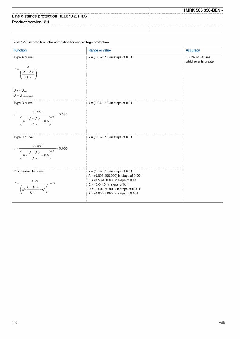
Table 172. Inverse time characteristics for overvoltage protection
Function Range or value Accuracy
Type A curve:
=- >
>
æ öç ÷è ø
tk
U U
U
EQUATION1436-SMALL V1 EN
U> = UsetU = Umeasured
k = (0.05-1.10) in steps of 0.01 ±5.0% or ±45 mswhichever is greater
Type B curve:
2.0
480
32 0.5
=⋅
− >⋅ −
0.035+
>
tk
U U
UEQUATION1437-SMALL V2 EN
k = (0.05-1.10) in steps of 0.01
Type C curve:
3.0
480
32 0.5
=⋅
⋅ −− >
0.035+
>
tk
U U
UEQUATION1438-SMALL V2 EN
k = (0.05-1.10) in steps of 0.01
Programmable curve:
×= +
- >× -
>
æ öç ÷è ø
P
k At D
U UB C
U
EQUATION1439-SMALL V1 EN
k = (0.05-1.10) in steps of 0.01A = (0.005-200.000) in steps of 0.001B = (0.50-100.00) in steps of 0.01C = (0.0-1.0) in steps of 0.1D = (0.000-60.000) in steps of 0.001P = (0.000-3.000) in steps of 0.001
1MRK 506 356-BEN -Line distance protection REL670 2.1 IEC Product version: 2.1
110 ABB
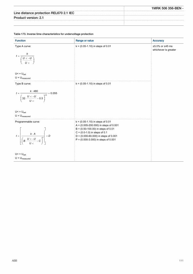
Table 173. Inverse time characteristics for undervoltage protection
Function Range or value Accuracy
Type A curve:
=< -
<
æ öç ÷è ø
kt
U U
U
EQUATION1431-SMALL V1 EN
U< = UsetU = Umeasured
k = (0.05-1.10) in steps of 0.01 ±5.0% or ±45 mswhichever is greater
Type B curve:
2.0
4800.055
32 0.5
×= +
< -× -
<
æ öç ÷è ø
kt
U U
U
EQUATION1432-SMALL V1 EN
U< = UsetU = Umeasured
k = (0.05-1.10) in steps of 0.01
Programmable curve:
×= +
< -× -
<
é ùê úê úê úæ öê úç ÷ë è ø û
P
k At D
U UB C
U
EQUATION1433-SMALL V1 EN
U< = UsetU = Umeasured
k = (0.05-1.10) in steps of 0.01A = (0.005-200.000) in steps of 0.001B = (0.50-100.00) in steps of 0.01C = (0.0-1.0) in steps of 0.1D = (0.000-60.000) in steps of 0.001P = (0.000-3.000) in steps of 0.001
1MRK 506 356-BEN -Line distance protection REL670 2.1 IEC Product version: 2.1
ABB 111
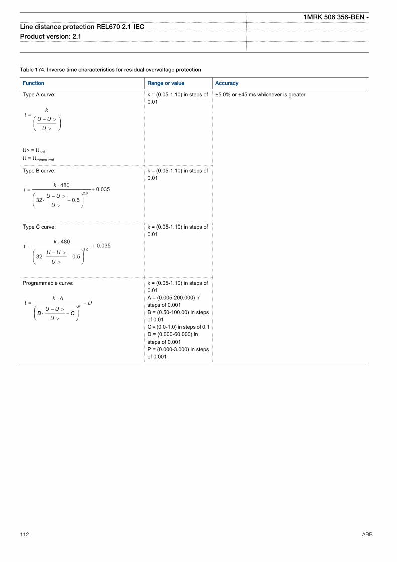
Table 174. Inverse time characteristics for residual overvoltage protection
Function Range or value Accuracy
Type A curve:
=- >
>
æ öç ÷è ø
tk
U U
U
EQUATION1436-SMALL V1 EN
U> = UsetU = Umeasured
k = (0.05-1.10) in steps of0.01
±5.0% or ±45 ms whichever is greater
Type B curve:
2.0
480
32 0.5
=⋅
− >⋅ −
0.035+
>
tk
U U
U
EQUATION1437-SMALL V2 EN
k = (0.05-1.10) in steps of0.01
Type C curve:
3.0
480
32 0.5
=⋅
⋅ −− >
0.035+
>
tk
U U
U
EQUATION1438-SMALL V2 EN
k = (0.05-1.10) in steps of0.01
Programmable curve:
×= +
- >× -
>
æ öç ÷è ø
P
k At D
U UB C
U
EQUATION1439-SMALL V1 EN
k = (0.05-1.10) in steps of0.01A = (0.005-200.000) insteps of 0.001B = (0.50-100.00) in stepsof 0.01C = (0.0-1.0) in steps of 0.1D = (0.000-60.000) insteps of 0.001P = (0.000-3.000) in stepsof 0.001
1MRK 506 356-BEN -Line distance protection REL670 2.1 IEC Product version: 2.1
112 ABB
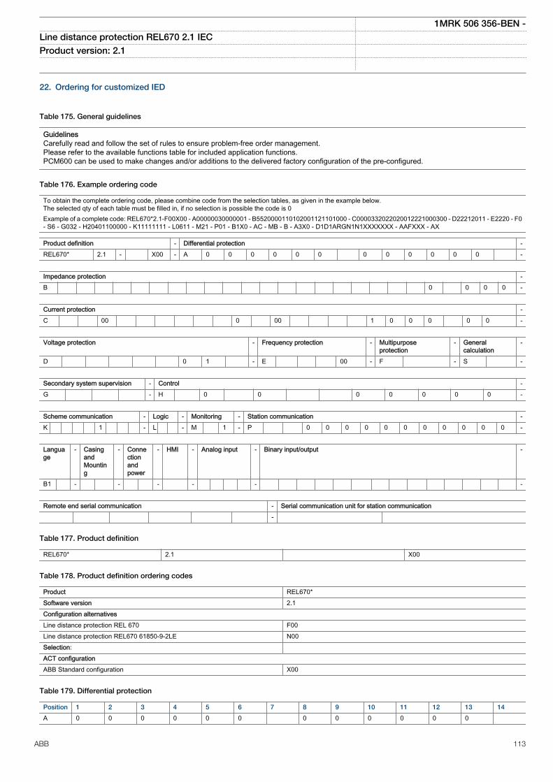
22. Ordering for customized IED
Table 175. General guidelines
GuidelinesCarefully read and follow the set of rules to ensure problem-free order management.Please refer to the available functions table for included application functions.PCM600 can be used to make changes and/or additions to the delivered factory configuration of the pre-configured.
Table 176. Example ordering code
To obtain the complete ordering code, please combine code from the selection tables, as given in the example below.The selected qty of each table must be filled in, if no selection is possible the code is 0Example of a complete code: REL670*2.1-F00X00 - A00000030000001 - B5520000110102001121101000 - C0000332022020012221000300 - D22212011 - E2220 - F0- S6 - G032 - H20401100000 - K11111111 - L0611 - M21 - P01 - B1X0 - AC - MB - B - A3X0 - D1D1ARGN1N1XXXXXXX - AAFXXX - AX
Product definition - Differential protection -REL670* 2.1 - X00 - A 0 0 0 0 0 0 0 0 0 0 0 0 -
Impedance protection -B 0 0 0 0 -
Current protection -C 00 0 00 1 0 0 0 0 0 -
Voltage protection - Frequency protection - Multipurposeprotection
- Generalcalculation
-
D 0 1 - E 00 - F - S -
Secondary system supervision - Control -G - H 0 0 0 0 0 0 0 -
Scheme communication - Logic - Monitoring - Station communication -K 1 - L - M 1 - P 0 0 0 0 0 0 0 0 0 0 0 -
Language
- CasingandMounting
- Connectionandpower
- HMI - Analog input - Binary input/output -
B1 - - - - - -
Remote end serial communication - Serial communication unit for station communication -
Table 177. Product definition
REL670* 2.1 X00
Table 178. Product definition ordering codes
Product REL670*Software version 2.1Configuration alternativesLine distance protection REL 670 F00Line distance protection REL670 61850-9-2LE N00Selection: ACT configurationABB Standard configuration X00
Table 179. Differential protection
Position 1 2 3 4 5 6 7 8 9 10 11 12 13 14
A 0 0 0 0 0 0 0 0 0 0 0 0
1MRK 506 356-BEN -Line distance protection REL670 2.1 IEC Product version: 2.1
ABB 113
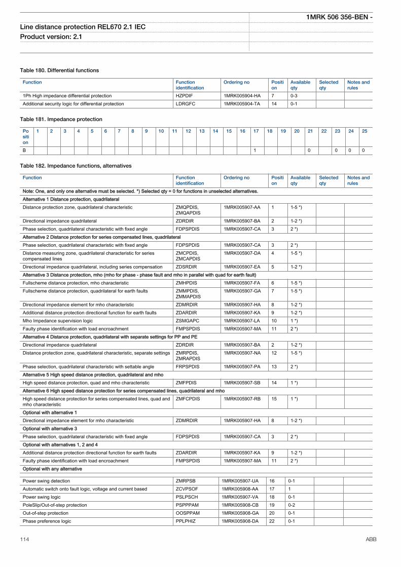
Table 180. Differential functions
Function Functionidentification
Ordering no Position
Availableqty
Selectedqty
Notes andrules
1Ph High impedance differential protection HZPDIF 1MRK005904-HA 7 0-3 Additional security logic for differential protection LDRGFC 1MRK005904-TA 14 0-1
Table 181. Impedance protection
Position
1 2 3 4 5 6 7 8 9 10 11 12 13 14 15 16 17 18 19 20 21 22 23 24 25
B 1 0 0 0 0
Table 182. Impedance functions, alternatives
Function Functionidentification
Ordering no Position
Availableqty
Selectedqty
Notes andrules
Note: One, and only one alternative must be selected. *) Selected qty = 0 for functions in unselected alternatives.Alternative 1 Distance protection, quadrilateralDistance protection zone, quadrilateral characteristic ZMQPDIS,
ZMQAPDIS1MRK005907-AA 1 1-5 *)
Directional impedance quadrilateral ZDRDIR 1MRK005907-BA 2 1-2 *) Phase selection, quadrilateral characteristic with fixed angle FDPSPDIS 1MRK005907-CA 3 2 *) Alternative 2 Distance protection for series compensated lines, quadrilateral Phase selection, quadrilateral characteristic with fixed angle FDPSPDIS 1MRK005907-CA 3 2 *) Distance measuring zone, quadrilateral characteristic for seriescompensated lines
ZMCPDIS,ZMCAPDIS
1MRK005907-DA 4 1-5 *)
Directional impedance quadrilateral, including series compensation ZDSRDIR 1MRK005907-EA 5 1-2 *) Alternative 3 Distance protection, mho (mho for phase - phase fault and mho in parallel with quad for earth fault) Fullscheme distance protection, mho characteristic ZMHPDIS 1MRK005907-FA 6 1-5 *) Fullscheme distance protection, quadrilateral for earth faults ZMMPDIS,
ZMMAPDIS1MRK005907-GA 7 1-5 *)
Directional impedance element for mho characteristic ZDMRDIR 1MRK005907-HA 8 1-2 *) Additional distance protection directional function for earth faults ZDARDIR 1MRK005907-KA 9 1-2 *) Mho Impedance supervision logic ZSMGAPC 1MRK005907-LA 10 1 *) Faulty phase identification with load encroachment FMPSPDIS 1MRK005907-MA 11 2 *) Alternative 4 Distance protection, quadrilateral with separate settings for PP and PE Directional impedance quadrilateral ZDRDIR 1MRK005907-BA 2 1-2 *) Distance protection zone, quadrilateral characteristic, separate settings ZMRPDIS,
ZMRAPDIS1MRK005907-NA 12 1-5 *)
Phase selection, quadrilateral characteristic with settable angle FRPSPDIS 1MRK005907-PA 13 2 *) Alternative 5 High speed distance protection, quadrilateral and mho High speed distance protection, quad and mho characteristic ZMFPDIS 1MRK005907-SB 14 1 *) Alternative 6 High speed distance protection for series compensated lines, quadrilateral and mho High speed distance protection for series compensated lines, quad andmho characteristic
ZMFCPDIS 1MRK005907-RB 15 1 *)
Optional with alternative 1Directional impedance element for mho characteristic ZDMRDIR 1MRK005907-HA 8 1-2 *) Optional with alternative 3Phase selection, quadrilateral characteristic with fixed angle FDPSPDIS 1MRK005907-CA 3 2 *) Optional with alternatives 1, 2 and 4Additional distance protection directional function for earth faults ZDARDIR 1MRK005907-KA 9 1-2 *) Faulty phase identification with load encroachment FMPSPDIS 1MRK005907-MA 11 2 *) Optional with any alternative
Power swing detection ZMRPSB 1MRK005907-UA 16 0-1 Automatic switch onto fault logic, voltage and current based ZCVPSOF 1MRK005908-AA 17 1 Power swing logic PSLPSCH 1MRK005907-VA 18 0-1 PoleSlip/Out-of-step protection PSPPPAM 1MRK005908-CB 19 0-2 Out-of-step protection OOSPPAM 1MRK005908-GA 20 0-1 Phase preference logic PPLPHIZ 1MRK005908-DA 22 0-1
1MRK 506 356-BEN -Line distance protection REL670 2.1 IEC Product version: 2.1
114 ABB

Table 183. Current protection
Position
1 2 3 4 5 6 7 8 9 10 11 12 13 14 15 16 17 18 19 20 21 22 23
C 00 0 00 1 0 0 0 0 0
Table 184. Current functions
Function Functionidentification
Ordering no Position
Availableqty
Selectedqty
Notes andrules
Instantaneous phase overcurrent protection PHPIOC 1MRK005910-AC 1 0-3 Four step phase overcurrent protection OC4PTOC 1MRK005910-BB 2 0-3 Instantaneous residual overcurrent protection EFPIOC 1MRK005910-DC 4 0-3 Four step residual overcurrent protection EF4PTOC 1MRK005910-EC 5 0-3 Four step directional negative phase sequence overcurrent protection NS4PTOC 1MRK005910-FB 6 0-2 Sensitive Directional residual over current and power protetcion SDEPSDE 1MRK005910-GA 7 0-1 Thermal overload protection, one time constant, Celcius LCPTTR 1MRK005911-BA 8 0-2 Thermal overload protection, one time constant, Fahrenheit LFPTTR 1MRK005911-AA 9 0-2 Breaker failure protection CCRBRF 1MRK005910-LA 11 0-2 Stub protection STBPTOC 1MRK005910-NA 13 0-1 Pole discordance protection CCPDSC 1MRK005910-PA 14 0-2 Directional Underpower protection GUPPDUP 1MRK005910-RA 15 0-2 Directional Overpower protection GOPPDOP 1MRK005910-TA 16 0-2 Broken conductor check BRCPTOC 1MRK005910-SA 17 1 Voltage restrained overcurrent protection VRPVOC 1MRK005910-XA 21 0-3
Table 185. Voltage protection
Position 1 2 3 4 5 6 7 8
D 0 1
Table 186. Voltage functions
Function Functionidentification
Ordering no Position
Availableqty
Selectedqty
Notes andrules
Two step undervoltage protection UV2PTUV 1MRK005912-AA 1 0-2 Two step overvoltage protection OV2PTOV 1MRK005912-BA 2 0-2 Two step residual overvoltage protection ROV2PTOV 1MRK005912-CC 3 0-2 Overexcitation protection OEXPVPH 1MRK005912-DA 4 0-1 Voltage differential protection VDCPTOV 1MRK005912-EA 5 0-2 Loss of voltage check LOVPTUV 1MRK005912-GA 7 1 Radial feeder protection PAPGAPC 1MRK005912-HA 8 0-1
Table 187. Frequency protection
Position 1 2 3 4
E 00
Table 188. Frequency functions
Function Functionidentification
Ordering no position
Availableqty
Selectedqty
Notes andrules
Underfrequency protection SAPTUF 1MRK005914-AA 1 0-6 Overfrequency protection SAPTOF 1MRK005914-BA 2 0-6 Rate-of-change frequency protection SAPFRC 1MRK005914-CA 3 0-6
Table 189. Multipurpose protection
Position 1
F
1MRK 506 356-BEN -Line distance protection REL670 2.1 IEC Product version: 2.1
ABB 115
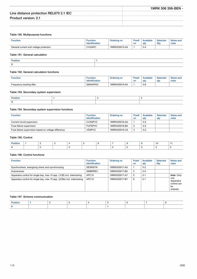
Table 190. Multipurpose functions
Function Functionidentification
Ordering no Position
Availableqty
SelectedQty
Notes andrules
General current and voltage protection CVGAPC 1MRK005915-AA 1 0-4
Table 191. General calculation
Position 1
S
Table 192. General calculation functions
Function Functionidentification
Ordering no Position
Availableqty
Selectedqty
Notes andrules
Frequency tracking filter SMAIHPAC 1MRK005915-KA 1 0-6
Table 193. Secondary system supervision
Position 1 2 3
G
Table 194. Secondary system supervision functions
Function Functionidentification
Ordering no Position
Availableqty
Selectedqty
Notes andrules
Current circuit supervison CCSSPVC 1MRK005916-AA 1 0-2 Fuse failure supervision FUFSPVC 1MRK005916-BA 2 0-3 Fuse failure supervision based on voltage difference VDSPVC 1MRK005916-CA 3 0-2
Table 195. Control
Position 1 2 3 4 5 6 7 8 9 10 11
H 0 0 0 0 0 0 0
Table 196. Control functions
Function Functionidentification
Ordering no Position
Availableqty
SelectedQty
Notes andrules
Synchrocheck, energizing check and synchronizing SESRSYN 1MRK005917-AA 1 0-2 Autorecloser SMBRREC 1MRK005917-BA 3 0-4 Apparatus control for single bay, max 10 app. (1CB) incl. Interlocking APC10 1MRK005917-AY 5 0-1 Note: Only
oneApparatuscontrol canbeordered.
Apparatus control for single bay, max 15 app. (2CBs) incl. Interlocking APC15 1MRK005917-BY 6 0-1
Table 197. Scheme communication
Position 1 2 3 4 5 6 7 8
K 1
1MRK 506 356-BEN -Line distance protection REL670 2.1 IEC Product version: 2.1
116 ABB
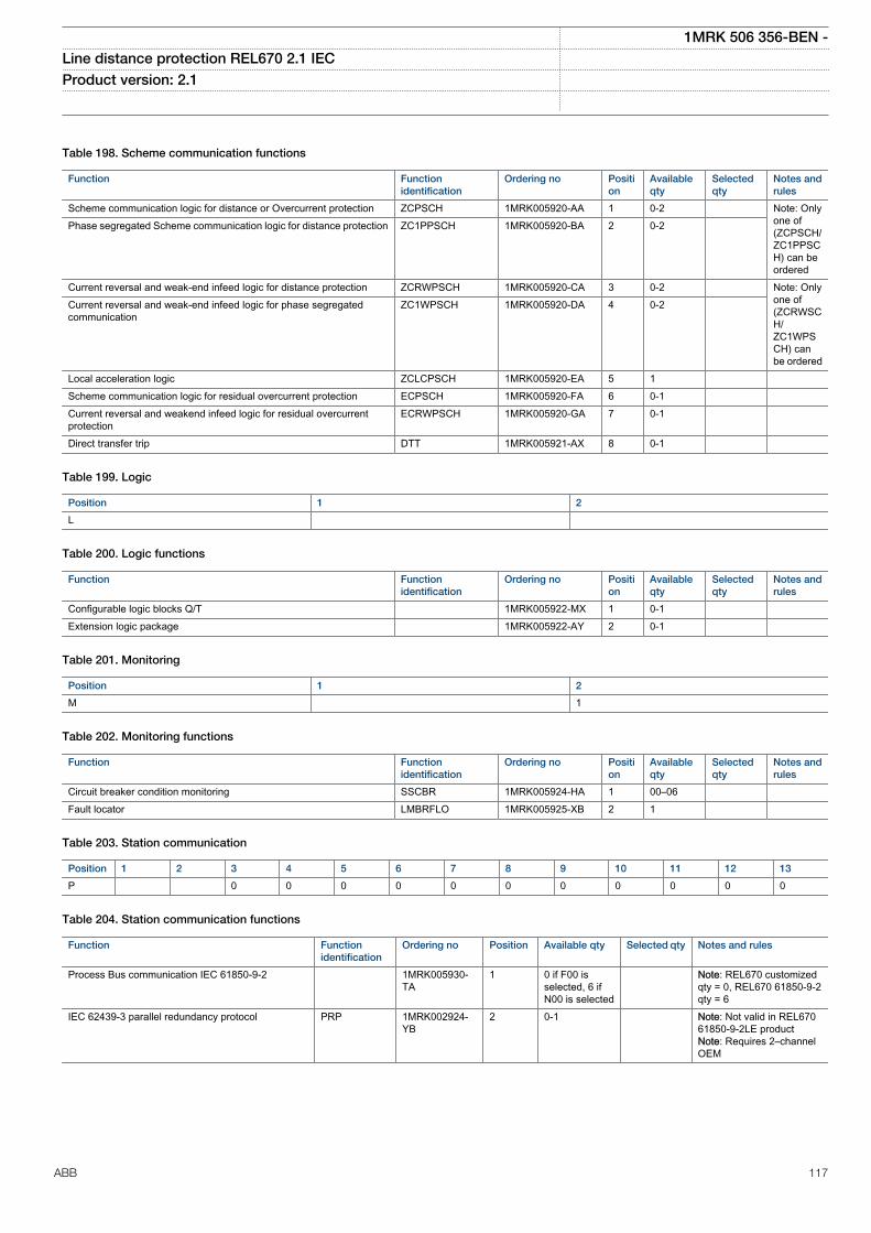
Table 198. Scheme communication functions
Function Functionidentification
Ordering no Position
Availableqty
Selectedqty
Notes andrules
Scheme communication logic for distance or Overcurrent protection ZCPSCH 1MRK005920-AA 1 0-2 Note: Onlyone of(ZCPSCH/ZC1PPSCH) can beordered
Phase segregated Scheme communication logic for distance protection ZC1PPSCH 1MRK005920-BA 2 0-2
Current reversal and weak-end infeed logic for distance protection ZCRWPSCH 1MRK005920-CA 3 0-2 Note: Onlyone of(ZCRWSCH/ZC1WPSCH) canbe ordered
Current reversal and weak-end infeed logic for phase segregatedcommunication
ZC1WPSCH 1MRK005920-DA 4 0-2
Local acceleration logic ZCLCPSCH 1MRK005920-EA 5 1 Scheme communication logic for residual overcurrent protection ECPSCH 1MRK005920-FA 6 0-1 Current reversal and weakend infeed logic for residual overcurrentprotection
ECRWPSCH 1MRK005920-GA 7 0-1
Direct transfer trip DTT 1MRK005921-AX 8 0-1
Table 199. Logic
Position 1 2
L
Table 200. Logic functions
Function Functionidentification
Ordering no Position
Availableqty
Selectedqty
Notes andrules
Configurable logic blocks Q/T 1MRK005922-MX 1 0-1 Extension logic package 1MRK005922-AY 2 0-1
Table 201. Monitoring
Position 1 2
M 1
Table 202. Monitoring functions
Function Functionidentification
Ordering no Position
Availableqty
Selectedqty
Notes andrules
Circuit breaker condition monitoring SSCBR 1MRK005924-HA 1 00–06 Fault locator LMBRFLO 1MRK005925-XB 2 1
Table 203. Station communication
Position 1 2 3 4 5 6 7 8 9 10 11 12 13
P 0 0 0 0 0 0 0 0 0 0 0
Table 204. Station communication functions
Function Functionidentification
Ordering no Position Available qty Selected qty Notes and rules
Process Bus communication IEC 61850-9-2 1MRK005930-TA
1 0 if F00 isselected, 6 ifN00 is selected
Note: REL670 customizedqty = 0, REL670 61850-9-2qty = 6
IEC 62439-3 parallel redundancy protocol PRP 1MRK002924-YB
2 0-1 Note: Not valid in REL67061850-9-2LE productNote: Requires 2–channelOEM
1MRK 506 356-BEN -Line distance protection REL670 2.1 IEC Product version: 2.1
ABB 117
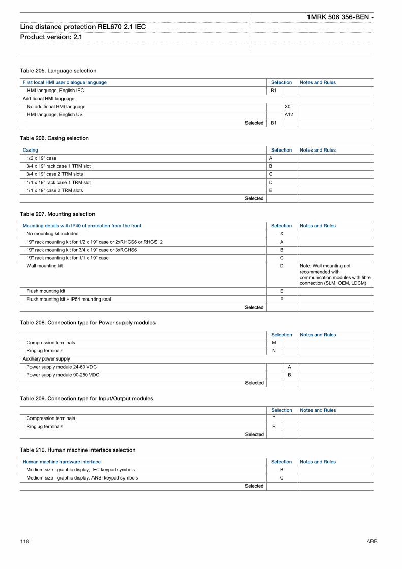
Table 205. Language selection
First local HMI user dialogue language Selection Notes and Rules
HMI language, English IEC B1 Additional HMI language No additional HMI language X0 HMI language, English US A12 Selected B1
Table 206. Casing selection
Casing Selection Notes and Rules
1/2 x 19" case A 3/4 x 19" rack case 1 TRM slot B 3/4 x 19" case 2 TRM slots C 1/1 x 19" rack case 1 TRM slot D 1/1 x 19" case 2 TRM slots E Selected
Table 207. Mounting selection
Mounting details with IP40 of protection from the front Selection Notes and Rules
No mounting kit included X 19" rack mounting kit for 1/2 x 19" case or 2xRHGS6 or RHGS12 A 19" rack mounting kit for 3/4 x 19" case or 3xRGHS6 B 19" rack mounting kit for 1/1 x 19" case C Wall mounting kit D Note: Wall mounting not
recommended withcommunication modules with fibreconnection (SLM, OEM, LDCM)
Flush mounting kit E Flush mounting kit + IP54 mounting seal F Selected
Table 208. Connection type for Power supply modules
Selection Notes and Rules
Compression terminals M Ringlug terminals N Auxiliary power supply Power supply module 24-60 VDC A Power supply module 90-250 VDC B Selected
Table 209. Connection type for Input/Output modules
Selection Notes and Rules
Compression terminals P Ringlug terminals R Selected
Table 210. Human machine interface selection
Human machine hardware interface Selection Notes and Rules
Medium size - graphic display, IEC keypad symbols B Medium size - graphic display, ANSI keypad symbols C Selected
1MRK 506 356-BEN -Line distance protection REL670 2.1 IEC Product version: 2.1
118 ABB
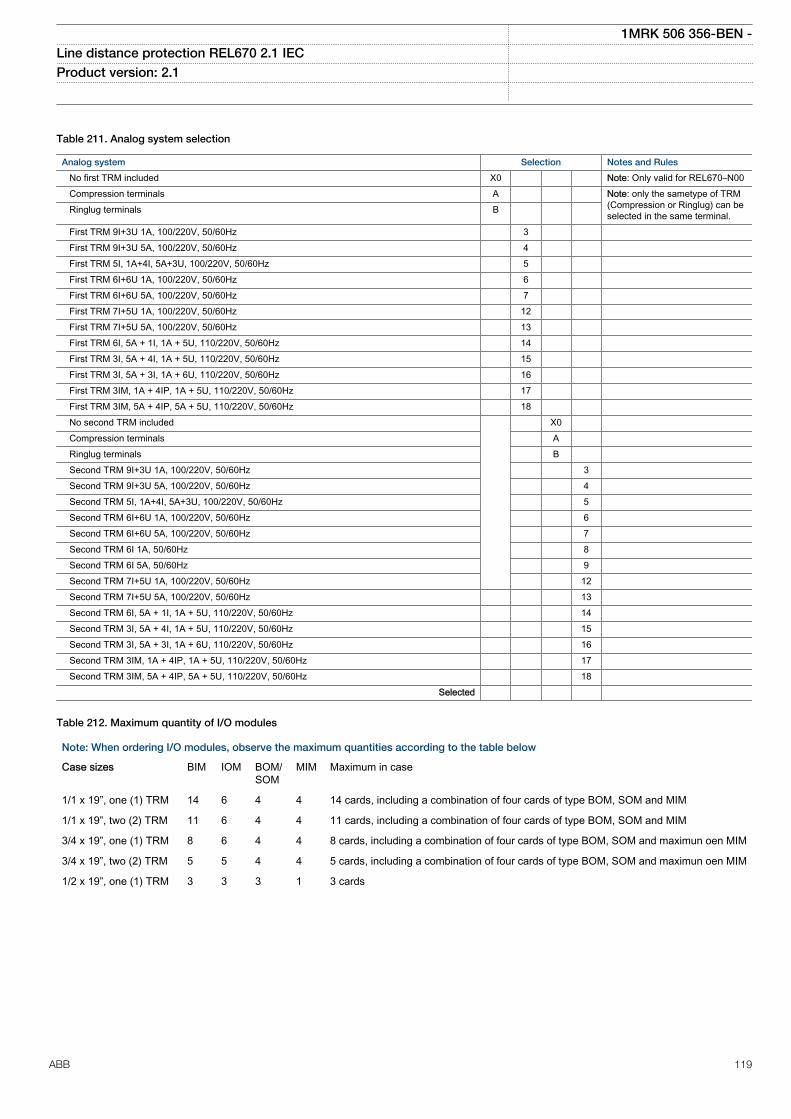
Table 211. Analog system selection
Analog system Selection Notes and Rules
No first TRM included X0 Note: Only valid for REL670–N00 Compression terminals A Note: only the sametype of TRM
(Compression or Ringlug) can beselected in the same terminal. Ringlug terminals B
First TRM 9I+3U 1A, 100/220V, 50/60Hz 3 First TRM 9I+3U 5A, 100/220V, 50/60Hz 4 First TRM 5I, 1A+4I, 5A+3U, 100/220V, 50/60Hz 5 First TRM 6I+6U 1A, 100/220V, 50/60Hz 6 First TRM 6I+6U 5A, 100/220V, 50/60Hz 7 First TRM 7I+5U 1A, 100/220V, 50/60Hz 12 First TRM 7I+5U 5A, 100/220V, 50/60Hz 13 First TRM 6I, 5A + 1I, 1A + 5U, 110/220V, 50/60Hz 14 First TRM 3I, 5A + 4I, 1A + 5U, 110/220V, 50/60Hz 15 First TRM 3I, 5A + 3I, 1A + 6U, 110/220V, 50/60Hz 16 First TRM 3IM, 1A + 4IP, 1A + 5U, 110/220V, 50/60Hz 17 First TRM 3IM, 5A + 4IP, 5A + 5U, 110/220V, 50/60Hz 18 No second TRM included X0 Compression terminals A Ringlug terminals B Second TRM 9I+3U 1A, 100/220V, 50/60Hz 3 Second TRM 9I+3U 5A, 100/220V, 50/60Hz 4 Second TRM 5I, 1A+4I, 5A+3U, 100/220V, 50/60Hz 5 Second TRM 6I+6U 1A, 100/220V, 50/60Hz 6 Second TRM 6I+6U 5A, 100/220V, 50/60Hz 7 Second TRM 6I 1A, 50/60Hz 8 Second TRM 6I 5A, 50/60Hz 9 Second TRM 7I+5U 1A, 100/220V, 50/60Hz 12 Second TRM 7I+5U 5A, 100/220V, 50/60Hz 13 Second TRM 6I, 5A + 1I, 1A + 5U, 110/220V, 50/60Hz 14 Second TRM 3I, 5A + 4I, 1A + 5U, 110/220V, 50/60Hz 15 Second TRM 3I, 5A + 3I, 1A + 6U, 110/220V, 50/60Hz 16 Second TRM 3IM, 1A + 4IP, 1A + 5U, 110/220V, 50/60Hz 17 Second TRM 3IM, 5A + 4IP, 5A + 5U, 110/220V, 50/60Hz 18 Selected
Table 212. Maximum quantity of I/O modules
Note: When ordering I/O modules, observe the maximum quantities according to the table below
Case sizes BIM IOM BOM/SOM
MIM Maximum in case
1/1 x 19”, one (1) TRM 14 6 4 4 14 cards, including a combination of four cards of type BOM, SOM and MIM
1/1 x 19”, two (2) TRM 11 6 4 4 11 cards, including a combination of four cards of type BOM, SOM and MIM
3/4 x 19”, one (1) TRM 8 6 4 4 8 cards, including a combination of four cards of type BOM, SOM and maximun oen MIM
3/4 x 19”, two (2) TRM 5 5 4 4 5 cards, including a combination of four cards of type BOM, SOM and maximun oen MIM
1/2 x 19”, one (1) TRM 3 3 3 1 3 cards
1MRK 506 356-BEN -Line distance protection REL670 2.1 IEC Product version: 2.1
ABB 119
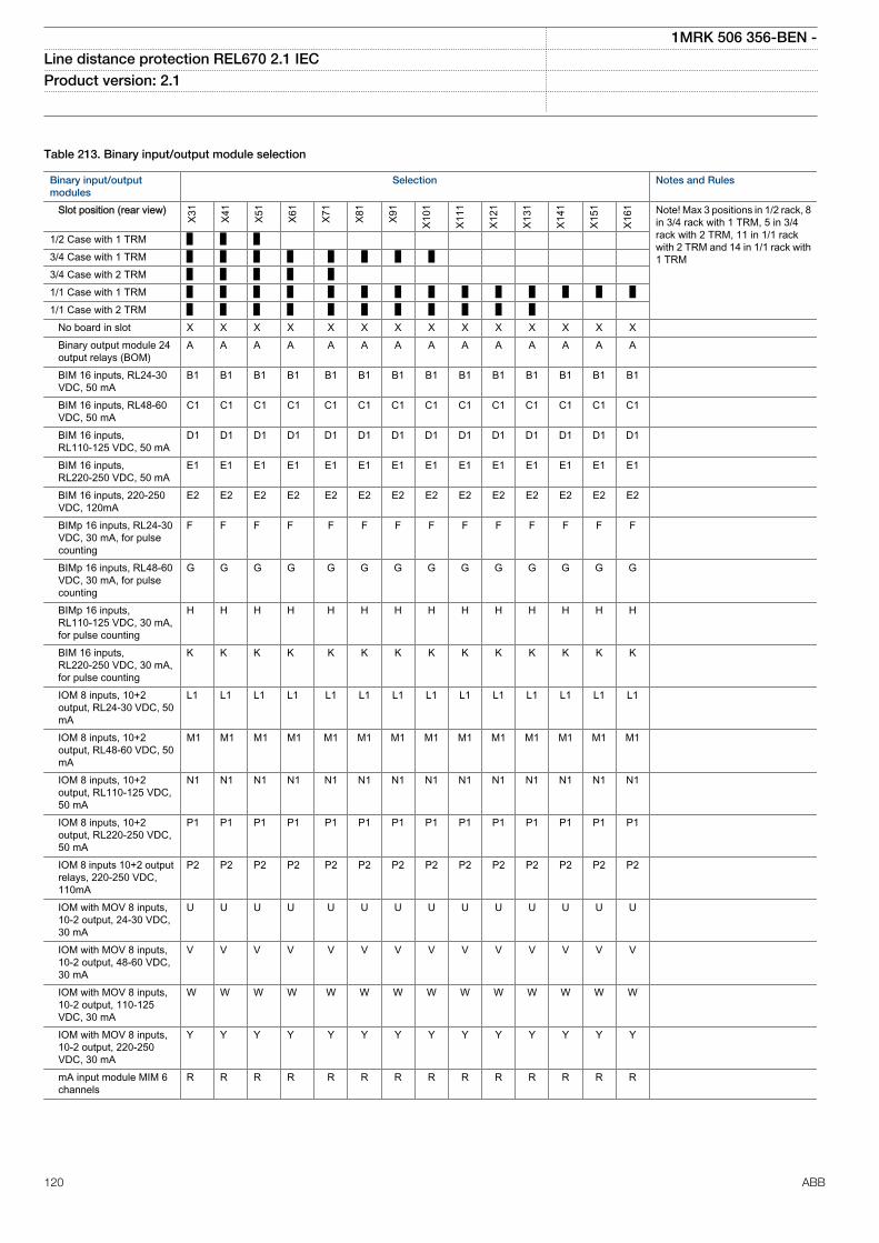
Table 213. Binary input/output module selection
Binary input/outputmodules
Selection Notes and Rules
Slot position (rear view)
X31
X41
X51
X61
X71
X81
X91
X101
X111
X121
X131
X141
X151
X161 Note! Max 3 positions in 1/2 rack, 8
in 3/4 rack with 1 TRM, 5 in 3/4rack with 2 TRM, 11 in 1/1 rackwith 2 TRM and 14 in 1/1 rack with1 TRM
1/2 Case with 1 TRM 3/4 Case with 1 TRM 3/4 Case with 2 TRM 1/1 Case with 1 TRM 1/1 Case with 2 TRM No board in slot X X X X X X X X X X X X X X Binary output module 24
output relays (BOM)A A A A A A A A A A A A A A
BIM 16 inputs, RL24-30VDC, 50 mA
B1 B1 B1 B1 B1 B1 B1 B1 B1 B1 B1 B1 B1 B1
BIM 16 inputs, RL48-60VDC, 50 mA
C1 C1 C1 C1 C1 C1 C1 C1 C1 C1 C1 C1 C1 C1
BIM 16 inputs,RL110-125 VDC, 50 mA
D1 D1 D1 D1 D1 D1 D1 D1 D1 D1 D1 D1 D1 D1
BIM 16 inputs,RL220-250 VDC, 50 mA
E1 E1 E1 E1 E1 E1 E1 E1 E1 E1 E1 E1 E1 E1
BIM 16 inputs, 220-250VDC, 120mA
E2 E2 E2 E2 E2 E2 E2 E2 E2 E2 E2 E2 E2 E2
BIMp 16 inputs, RL24-30VDC, 30 mA, for pulsecounting
F F F F F F F F F F F F F F
BIMp 16 inputs, RL48-60VDC, 30 mA, for pulsecounting
G G G G G G G G G G G G G G
BIMp 16 inputs,RL110-125 VDC, 30 mA,for pulse counting
H H H H H H H H H H H H H H
BIM 16 inputs,RL220-250 VDC, 30 mA,for pulse counting
K K K K K K K K K K K K K K
IOM 8 inputs, 10+2output, RL24-30 VDC, 50mA
L1 L1 L1 L1 L1 L1 L1 L1 L1 L1 L1 L1 L1 L1
IOM 8 inputs, 10+2output, RL48-60 VDC, 50mA
M1 M1 M1 M1 M1 M1 M1 M1 M1 M1 M1 M1 M1 M1
IOM 8 inputs, 10+2output, RL110-125 VDC,50 mA
N1 N1 N1 N1 N1 N1 N1 N1 N1 N1 N1 N1 N1 N1
IOM 8 inputs, 10+2output, RL220-250 VDC,50 mA
P1 P1 P1 P1 P1 P1 P1 P1 P1 P1 P1 P1 P1 P1
IOM 8 inputs 10+2 outputrelays, 220-250 VDC,110mA
P2 P2 P2 P2 P2 P2 P2 P2 P2 P2 P2 P2 P2 P2
IOM with MOV 8 inputs,10-2 output, 24-30 VDC,30 mA
U U U U U U U U U U U U U U
IOM with MOV 8 inputs,10-2 output, 48-60 VDC,30 mA
V V V V V V V V V V V V V V
IOM with MOV 8 inputs,10-2 output, 110-125VDC, 30 mA
W W W W W W W W W W W W W W
IOM with MOV 8 inputs,10-2 output, 220-250VDC, 30 mA
Y Y Y Y Y Y Y Y Y Y Y Y Y Y
mA input module MIM 6channels
R R R R R R R R R R R R R R
1MRK 506 356-BEN -Line distance protection REL670 2.1 IEC Product version: 2.1
120 ABB
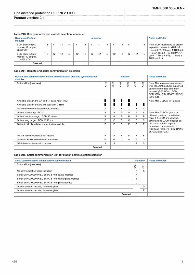
Table 213. Binary input/output module selection, continuedBinary input/outputmodules
Selection Notes and Rules
SOM Static outputmodule, 12 outputs,48-60 VDC
T1 T1 T1 T1 T1 T1 T1 T1 T1 T1 T1 T1 T1 T1 Note: SOM must not to be placedin position nearest to NUM; 1/2case slot P5, 3/4 case 1 TRM slotP10, 3/4 case 2 TRM slot P7, 1/1case 1 TRM slot P16, 1/1 case 2TRM slot P13
SOM static outputsmodule, 12 outputs,110-250 VDC
T2 T2 T2 T2 T2 T2 T2 T2 T2 T2 T2 T2 T2 T2
Selected.
Table 214. Remote end serial communication selection
Remote end communication, station communication and time synchronizationmodules
Selection Notes and Rules
Slot position (rear view)
X312
X313
X302
X303
X322
X323 Note: The maximum number and
type of LDCM modules supporteddepend on the total amount ofmodules (BIM, BOM, LDCM,OEM, GTM, SLM, RS485, IRIG-B)in the IED.
Available slots in 1/2, 3/4 and 1/1 case with 1TRM Note: Max 2 LDCM in 1/2 case Available slots in 3/4 and 1/1 case with 2 TRM No remote communication board included X X X X X X Optical short range LDCM A A A A A A Note: Max 2 LDCM (same or
different type) can be selectedRule: if 2 LDCM are selected,always place LDCM modules onthe same board to supportredundant communication; inP30:2 and P30:3, P31:2 and P31:3or P32:2 and P32:3
Optical medium range, LDCM 1310 nm B B B B B B Optical long range, LDCM 1550 nm C C C C C C Galvanic X21 line data communication module E E E E E E
IRIG-B Time synchronization module F F F F F F Galvanic RS485 communication module G G G G G G GPS time synchronization module S S S S Selected
Table 215. Serial communication unit for station communication selection
Serial communication unit for station communication Selection Notes and Rules
Slot position (rear view)
X301
X311
No communication board included X X Serial SPA/LON/DNP/IEC 60870-5-103 plastic interface A Serial SPA/LON/DNP/IEC 60870-5-103 plastic/glass interface B Serial SPA/LON/DNP/IEC 60870-5-103 glass interface C Optical ethernet module, 1 channel glass D Optical ethernet module, 2 channel glass E Selected.
1MRK 506 356-BEN -Line distance protection REL670 2.1 IEC Product version: 2.1
ABB 121
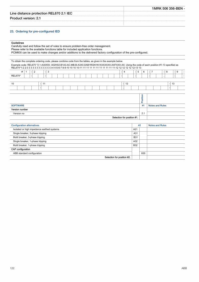
23. Ordering for pre-configured IED
GuidelinesCarefully read and follow the set of rules to ensure problem-free order management.Please refer to the available functions table for included application functions.PCM600 can be used to make changes and/or additions to the delivered factory configuration of the pre-configured.
To obtain the complete ordering code, please combine code from the tables, as given in the example below.Example code: REL670 *2.1-A30X00- A02H02-B1A3-AC-MB-B-A3X0-DAB1RGN1N1XXXXXXX-AXFXXX-AX. Using the code of each position #1-13 specified asREL670*1-2 2-3 3 3 3 3 3 3 3 3 3 3 3 3-4 4-5-6-7 8-9-10 10 10 10-11 11 11 11 11 11 11 11 11 11 11-12 12 12 12 12 12-13 13
# 1 - 2 - 3 - 4 - 5 6 - 7 - 8 - 9 -REL670* - - - - - . - -
10 - 11 - 12 - 13 - . -
Po
sitio
n
SOFTWARE #1 Notes and Rules
Version number Version no 2.1
Selection for position #1.
Configuration alternatives #2 Notes and Rules
Isolated or high impedance earthed systems A21 Single breaker, 3-phase tripping A31 Multi breaker, 3-phase tripping B31 Single breaker, 1-phase tripping A32 Multi breaker, 1-phase tripping B32 CAP configuration ABB standard configuration X00 Selection for position #2.
1MRK 506 356-BEN -Line distance protection REL670 2.1 IEC Product version: 2.1
122 ABB
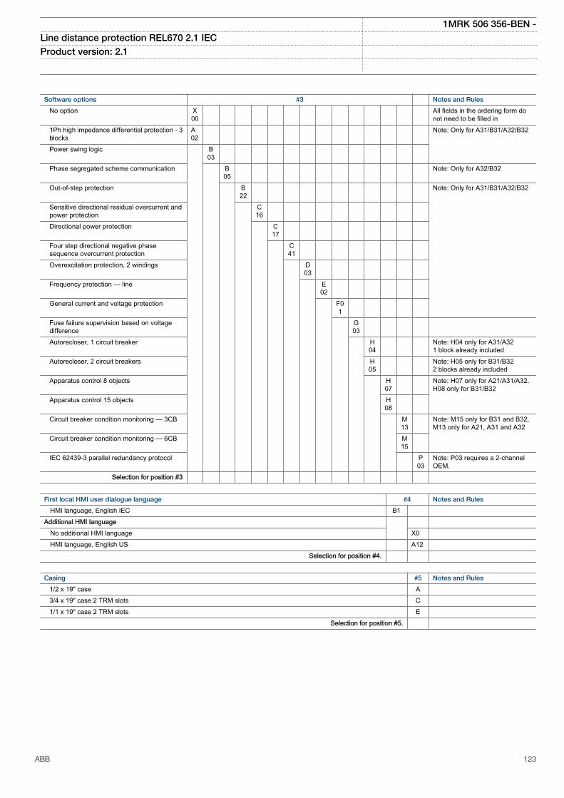
Software options #3 Notes and Rules
No option X00
All fields in the ordering form donot need to be filled in
1Ph high impedance differential protection - 3blocks
A02
Note: Only for A31/B31/A32/B32
Power swing logic B03
Phase segregated scheme communication B05
Note: Only for A32/B32
Out-of-step protection B22
Note: Only for A31/B31/A32/B32
Sensitive directional residual overcurrent andpower protection
C16
Directional power protection C17
Four step directional negative phasesequence overcurrent protection
C41
Overexcitation protection, 2 windings D03
Frequency protection — line E02
General current and voltage protection F01
Fuse failure supervision based on voltagedifference
G03
Autorecloser, 1 circuit breaker H04
Note: H04 only for A31/A321 block already included
Autorecloser, 2 circuit breakers H05
Note: H05 only for B31/B322 blocks already included
Apparatus control 8 objects H07
Note: H07 only for A21/A31/A32.H08 only for B31/B32
Apparatus control 15 objects H08
Circuit breaker condition monitoring — 3CB M13
Note: M15 only for B31 and B32,M13 only for A21, A31 and A32
Circuit breaker condition monitoring — 6CB M15
IEC 62439-3 parallel redundancy protocol P03
Note: P03 requires a 2-channelOEM.
Selection for position #3
First local HMI user dialogue language #4 Notes and Rules
HMI language, English IEC B1 Additional HMI language No additional HMI language X0 HMI language, English US A12 Selection for position #4.
Casing #5 Notes and Rules
1/2 x 19" case A 3/4 x 19" case 2 TRM slots C 1/1 x 19" case 2 TRM slots E Selection for position #5.
1MRK 506 356-BEN -Line distance protection REL670 2.1 IEC Product version: 2.1
ABB 123
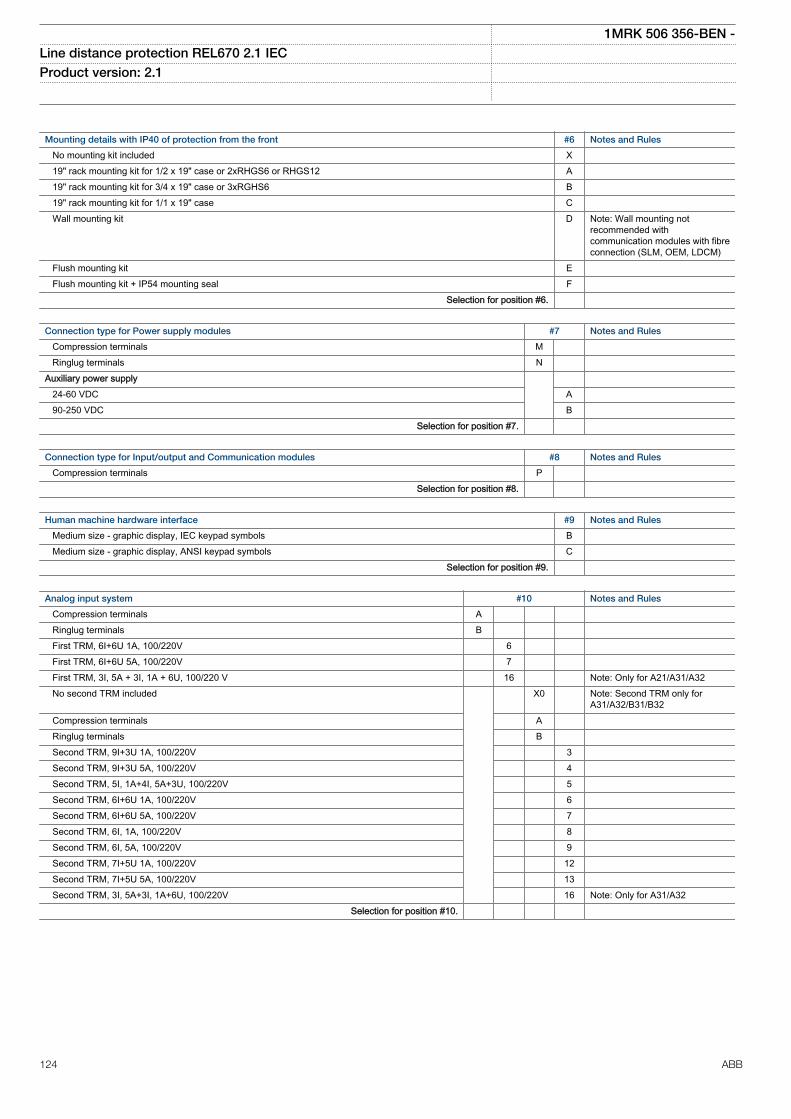
Mounting details with IP40 of protection from the front #6 Notes and Rules
No mounting kit included X 19" rack mounting kit for 1/2 x 19" case or 2xRHGS6 or RHGS12 A 19" rack mounting kit for 3/4 x 19" case or 3xRGHS6 B 19" rack mounting kit for 1/1 x 19" case C Wall mounting kit D Note: Wall mounting not
recommended withcommunication modules with fibreconnection (SLM, OEM, LDCM)
Flush mounting kit E Flush mounting kit + IP54 mounting seal F Selection for position #6.
Connection type for Power supply modules #7 Notes and Rules
Compression terminals M Ringlug terminals N Auxiliary power supply 24-60 VDC A 90-250 VDC B Selection for position #7.
Connection type for Input/output and Communication modules #8 Notes and Rules
Compression terminals P Selection for position #8.
Human machine hardware interface #9 Notes and Rules
Medium size - graphic display, IEC keypad symbols B Medium size - graphic display, ANSI keypad symbols C Selection for position #9.
Analog input system #10 Notes and Rules
Compression terminals A Ringlug terminals B First TRM, 6I+6U 1A, 100/220V 6 First TRM, 6I+6U 5A, 100/220V 7 First TRM, 3I, 5A + 3I, 1A + 6U, 100/220 V 16 Note: Only for A21/A31/A32 No second TRM included X0 Note: Second TRM only for
A31/A32/B31/B32 Compression terminals A Ringlug terminals B Second TRM, 9I+3U 1A, 100/220V 3 Second TRM, 9I+3U 5A, 100/220V 4 Second TRM, 5I, 1A+4I, 5A+3U, 100/220V 5 Second TRM, 6I+6U 1A, 100/220V 6 Second TRM, 6I+6U 5A, 100/220V 7 Second TRM, 6I, 1A, 100/220V 8 Second TRM, 6I, 5A, 100/220V 9 Second TRM, 7I+5U 1A, 100/220V 12 Second TRM, 7I+5U 5A, 100/220V 13 Second TRM, 3I, 5A+3I, 1A+6U, 100/220V 16 Note: Only for A31/A32 Selection for position #10.
1MRK 506 356-BEN -Line distance protection REL670 2.1 IEC Product version: 2.1
124 ABB
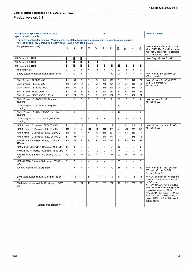
Binary input/output module, mA and timesynchronization boards.
#11 Notes and Rules
For pulse counting, for example kWh metering, the BIM with enhanced pulse counting capabilities must be used.Note: 1BIM and 1 BOM included In A31/A32/B31/B32, 1 IOM basic in A21.
Slot position (rear view)
X31
X41
X51
X61
X71
X81
X91
X101
X111
X121
X131 Note: Max 3 positions in 1/2 rack
with 1 TRM, Max 5 positions in 3/4rack with 2 TRM, Max 11 positionsin 1/1 rack with 2 TRM
1/2 Case with 1 TRM Note: Only 1/2 case for A21.3/4 Case with 2 TRM 1/1 Case with 2 TRM No board in slot X X X X X X X X X X X Binary output module 24 output relays (BOM) A A A A A A A A A A Note: Maximum 4 (BOM+SOM
+MIM) boards. BIM 16 inputs, RL24-30 VDC B1 B1 B1 B1 B1 B1 B1 B1 B1 B1 B1 Note: X31 only for A31/A32/B31/
B32, X41 only for A21X51 not in B32 BIM 16 inputs, RL48-60 VDC C1 C1 C1 C1 C1 C1 C1 C1 C1 C1 C1
BIM 16 inputs, RL110-125 VDC D1 D1 D1 D1 D1 D1 D1 D1 D1 D1 D1 BIM 16 inputs, RL220-250 VDC E1 E1 E1 E1 E1 E1 E1 E1 E1 E1 E1 BIM 16 inputs, 220-250 VDC, 120mA E2 E2 E2 E2 E2 E2 E2 E2 E2 E2 E2 BIMp 16 inputs, RL24-30 VDC, for pulse
counting F F F F F F F F F F Note: X41 only for A21
X51 not in B32 BIMp 16 inputs, RL48-60 VDC, for pulse
counting G G G G G G G G G G
BIMp 16 inputs, RL110-125 VDC, for pulsecounting
H H H H H H H H H H
BIMp 16 inputs, RL220-250 VDC, for pulsecounting
K K K K K K K K K K
IOM 8 inputs, 10+2 output, RL24-30 VDC L1 L1 L1 L1 L1 L1 L1 L1 L1 L1 L1 Note: X31 and X41 only for A21,X51 not in B32 IOM 8 inputs, 10+2 output, RL48-60 VDC M1 M1 M1 M1 M1 M1 M1 M1 M1 M1 M1
IOM 8 inputs, 10+2 output, RL110-125 VDC N1 N1 N1 N1 N1 N1 N1 N1 N1 N1 N1 IOM 8 inputs, 10+2 output, RL220-250 VDC P1 P1 P1 P1 P1 P1 P1 P1 P1 P1 P1 IOM 8 inputs 10+2 output relays, 220-250 VDC,
110mAP2 P2 P2 P2 P2 P2 P2 P2 P2 P2 P2
IOM with MOV 8 inputs, 10-2 output, 24-30 VDC U U U U U U U U U U U IOM with MOV 8 inputs, 10-2 output, 48-60 VDC V V V V V V V V V V V IOM with MOV 8 inputs, 10-2 output, 110-125
VDCW W W W W W W W W W W
IOM with MOV 8 inputs, 10-2 output, 220-250VDC
Y Y Y Y Y Y Y Y Y Y Y
mA input module MIM 6 channels R R R R R R R R R R Note: Maximum 1 MIM board in1/2 case. X51 not for B32X41 only for A21.
SOM Static output module, 12 outputs, 48-60VDC
T1 T1 T1 T1 T1 T1 T1 T1 T1 T1 No SOM board in slot X51 for 1/2case, X71 for 3/4 case and X131for 1/1 case.X41 only for A21. X51 not in B32Note: SOM must not to be placedin position nearest to NUM; 1/2case slot P5, 3/4 case 1 TRM slotP10, 3/4 case 2 TRM slot P7, 1/1case 1 TRM slot P16, 1/1 case 2TRM slot P13
SOM static outputs module, 12 outputs, 110-250VDC
T2 T2 T2 T2 T2 T2 T2 T2 T2 T2
Selection for position #11.
1MRK 506 356-BEN -Line distance protection REL670 2.1 IEC Product version: 2.1
ABB 125
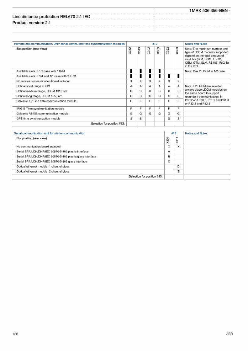
Remote end communication, DNP serial comm. and time synchronization modules #12 Notes and Rules
Slot position (rear view)
X312
X313
X302
X303
X322
X323 Note: The maximum number and
type of LDCM modules supporteddepend on the total amount ofmodules (BIM, BOM, LDCM,OEM, GTM, SLM, RS485, IRIG-B)in the IED.
Available slots in 1/2 case with 1TRM Note: Max 2 LDCM in 1/2 case Available slots in 3/4 and 1/1 case with 2 TRM No remote communication board included X X X X X X Optical short range LDCM A A A A A A Note: if 2 LDCM are selected,
always place LDCM modules onthe same board to supportredundant communication; inP30:2 and P30:3, P31:2 and P31:3or P32:2 and P32:3
Optical medium range, LDCM 1310 nm B B B B B B Optical long range, LDCM 1550 nm C C C C C C Galvanic X21 line data communication module E E E E E E
IRIG-B Time synchronization module F F F F F F Galvanic RS485 communication module G G G G G G GPS time synchronization module S S S S Selection for position #12.
Serial communication unit for station communication #13 Notes and Rules
Slot position (rear view)
X301
X311
No communication board included X X Serial SPA/LON/DNP/IEC 60870-5-103 plastic interface A Serial SPA/LON/DNP/IEC 60870-5-103 plastic/glass interface B Serial SPA/LON/DNP/IEC 60870-5-103 glass interface C Optical ethernet module, 1 channel glass D Optical ethernet module, 2 channel glass E Selection for position #13.
1MRK 506 356-BEN -Line distance protection REL670 2.1 IEC Product version: 2.1
126 ABB
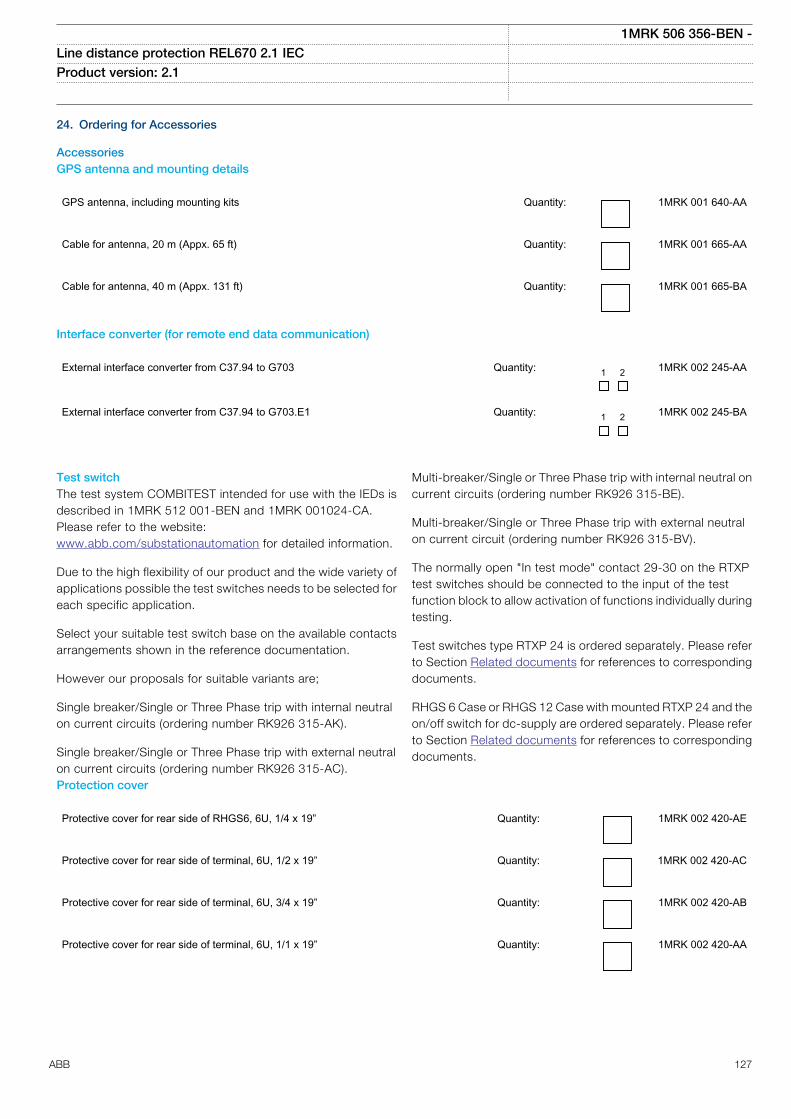
24. Ordering for Accessories
AccessoriesGPS antenna and mounting details
GPS antenna, including mounting kits Quantity: 1MRK 001 640-AA
Cable for antenna, 20 m (Appx. 65 ft) Quantity: 1MRK 001 665-AA
Cable for antenna, 40 m (Appx. 131 ft) Quantity: 1MRK 001 665-BA
Interface converter (for remote end data communication)
External interface converter from C37.94 to G703 Quantity: 1 2 1MRK 002 245-AA
External interface converter from C37.94 to G703.E1 Quantity: 1 2 1MRK 002 245-BA
Test switchThe test system COMBITEST intended for use with the IEDs isdescribed in 1MRK 512 001-BEN and 1MRK 001024-CA.Please refer to the website:www.abb.com/substationautomation for detailed information.
Due to the high flexibility of our product and the wide variety ofapplications possible the test switches needs to be selected foreach specific application.
Select your suitable test switch base on the available contactsarrangements shown in the reference documentation.
However our proposals for suitable variants are;
Single breaker/Single or Three Phase trip with internal neutralon current circuits (ordering number RK926 315-AK).
Single breaker/Single or Three Phase trip with external neutralon current circuits (ordering number RK926 315-AC).
Multi-breaker/Single or Three Phase trip with internal neutral oncurrent circuits (ordering number RK926 315-BE).
Multi-breaker/Single or Three Phase trip with external neutralon current circuit (ordering number RK926 315-BV).
The normally open "In test mode" contact 29-30 on the RTXPtest switches should be connected to the input of the testfunction block to allow activation of functions individually duringtesting.
Test switches type RTXP 24 is ordered separately. Please referto Section Related documents for references to correspondingdocuments.
RHGS 6 Case or RHGS 12 Case with mounted RTXP 24 and theon/off switch for dc-supply are ordered separately. Please referto Section Related documents for references to correspondingdocuments.
Protection cover
Protective cover for rear side of RHGS6, 6U, 1/4 x 19” Quantity: 1MRK 002 420-AE
Protective cover for rear side of terminal, 6U, 1/2 x 19” Quantity: 1MRK 002 420-AC
Protective cover for rear side of terminal, 6U, 3/4 x 19” Quantity: 1MRK 002 420-AB
Protective cover for rear side of terminal, 6U, 1/1 x 19” Quantity: 1MRK 002 420-AA
1MRK 506 356-BEN -Line distance protection REL670 2.1 IEC Product version: 2.1
ABB 127
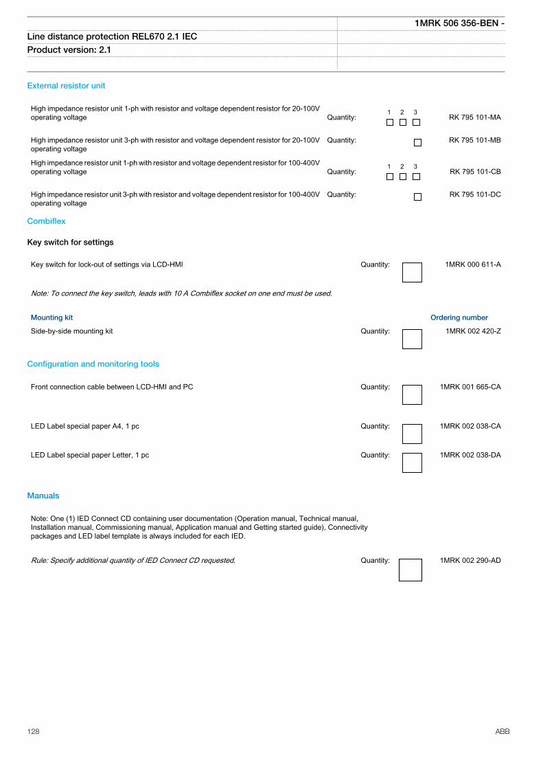
External resistor unit
High impedance resistor unit 1-ph with resistor and voltage dependent resistor for 20-100Voperating voltage
Quantity:
1 2 3 RK 795 101-MA
High impedance resistor unit 3-ph with resistor and voltage dependent resistor for 20-100Voperating voltage
Quantity: RK 795 101-MB
High impedance resistor unit 1-ph with resistor and voltage dependent resistor for 100-400Voperating voltage
Quantity:
1 2 3 RK 795 101-CB
High impedance resistor unit 3-ph with resistor and voltage dependent resistor for 100-400Voperating voltage
Quantity: RK 795 101-DC
Combiflex
Key switch for settings
Key switch for lock-out of settings via LCD-HMI Quantity: 1MRK 000 611-A
Note: To connect the key switch, leads with 10 A Combiflex socket on one end must be used.
Mounting kit Ordering number
Side-by-side mounting kit Quantity: 1MRK 002 420-Z
Configuration and monitoring tools
Front connection cable between LCD-HMI and PC Quantity: 1MRK 001 665-CA
LED Label special paper A4, 1 pc Quantity: 1MRK 002 038-CA
LED Label special paper Letter, 1 pc Quantity: 1MRK 002 038-DA
Manuals
Note: One (1) IED Connect CD containing user documentation (Operation manual, Technical manual,Installation manual, Commissioning manual, Application manual and Getting started guide), Connectivitypackages and LED label template is always included for each IED.
Rule: Specify additional quantity of IED Connect CD requested. Quantity: 1MRK 002 290-AD
1MRK 506 356-BEN -Line distance protection REL670 2.1 IEC Product version: 2.1
128 ABB
User documentation
Rule: Specify the number of printed manuals requested
Application manual IEC Quantity: 1MRK 506 353-UEN
ANSI Quantity: 1MRK 506 338-UUS
Technical manual IEC Quantity: 1MRK 506 354-UEN
ANSI Quantity: 1MRK 506 339-UUS
Commissioning manual IEC Quantity: 1MRK 506 355-UEN
ANSI Quantity: 1MRK 506 340-UUS
Communication protocol manual, IEC 61850 Edition 1
IEC Quantity: 1MRK 511 349-UEN
Communication protocol manual, IEC 61850 Edition 2 IEC Quantity: 1MRK 511 350-UEN
Communication protocol manual, IEC 60870-5-103 IEC Quantity: 1MRK 511 351-UEN
Communication protocol manual, LON IEC Quantity: 1MRK 511 352-UEN
Communication protocol manual, SPA IEC Quantity: 1MRK 511 353-UEN
Communication protocol manual, DNP ANSI Quantity: 1MRK 511 348-UUS
Point list manual, DNP ANSI Quantity 1MRK 511 354-UUS
Operation manual IEC Quantity: 1MRK 500 123-UEN
ANSI Quantity: 1MRK 500 123-UUS
Installation manual IEC Quantity: 1MRK 514 024-UEN
ANSI Quantity: 1MRK 514 024-UUS
1MRK 506 356-BEN -Line distance protection REL670 2.1 IEC Product version: 2.1
ABB 129
Engineering manual, 670 series IEC Quantity: 1MRK 511 355-UEN
ANSI Quantity: 1MRK 511 355-UUS
Cyber security guideline IEC Quantity: 1MRK 511 356-UEN
Reference information
For our reference and statistics we would be pleased to be provided with the following application data:
Country: End user:
Station name: Voltage level: kV
Related documents
Documents related to REL670 Document numbers
Application manual IEC:1MRK 506 353-UENANSI:1MRK 506 353-UUS
Commissioning manual IEC:1MRK 506 355-UENANSI:1MRK 506 355-UUS
Product guide 1MRK 506 356-BEN
Technical manual IEC:1MRK 506 354-UENANSI:1MRK 506 354-UUS
Type test certificate IEC:1MRK 506 356-TENANSI:1MRK 506 356-TUS
670 series manuals Document numbers
Operation manual IEC:1MRK 500 123-UENANSI:1MRK 500 123-UUS
Engineering manual IEC:1MRK 511 355-UENANSI:1MRK 511 355-UUS
Installation manual IEC:1MRK 514 024-UENANSI:1MRK 514 024-UUS
Communication protocol manual,DNP3
1MRK 511 348-UUS
Communication protocol manual,IEC 60870-5-103
1MRK 511 351-UEN
Communication protocol manual,IEC 61850 Edition 1
1MRK 511 349-UEN
Communication protocol manual,IEC 61850 Edition 2
1MRK 511 350-UEN
Communication protocol manual,LON
1MRK 511 352-UEN
Communication protocol manual,SPA
1MRK 511 353-UEN
Point list manual, DNP3 1MRK 511 354-UUS
Accessories guide IEC:1MRK 514 012-BENANSI:1MRK 514 012-BUS
Cyber security deploymentguideline
1MRK 511 356-UEN
Connection and Installationcomponents
1MRK 513 003-BEN
Test system, COMBITEST 1MRK 512 001-BEN
1MRK 506 356-BEN -Line distance protection REL670 2.1 IEC Product version: 2.1
130 ABB

131
Contact us
ABB ABSubstation Automation ProductsSE-721 59 Västerås, SwedenPhone +46 (0) 21 32 50 00Fax +46 (0) 21 14 69 18
www.abb.com/substationautomation
1MR
K 5
06 3
56-B
EN
-©
Cop
yrig
ht 2
015
AB
B. A
ll rig
hts
rese
rved
.