Lincoln Quicklub centralized and automatic lubrication · PDF fileQuicklub® Lubrication...
40
Lincoln Quicklub centralized and automatic lubrication systems
Transcript of Lincoln Quicklub centralized and automatic lubrication · PDF fileQuicklub® Lubrication...
Lincoln Quicklub centralized and automatic lubrication systems

People, capabilities and systems to save money and increase productivity
We’re the largest and most successful company in our field because we continu-ally satisfy our customers with the world’s best lubrication and pumping systems. For more than a century, companies have relied on our technical and quality leader-ship, our world-class manufacturing and customer service, and our vast network of distributors and support facilities.
Lincoln develops new products and systems at research and development facilities in the U.S., Germany and India that provide global and regional applica-tion solutions.
We have solutions for large processing plants, automotive manufacturing, pulp and paper mills, and food and beverage facilities. Virtually every industrial professional involved in operations and maintenance can benefit from Lincoln systems.
On the road or in the field, Lincoln pro-tects heavy equipment used in mining, construction, agriculture and over-the-road trucking. The world’s leading manufacturers offer our systems as standard equipment or factory options.
Lincoln builds precision metal compo-nents, state-of-the-art electronic con-trols, and the industry’s top-performing pump systems. Our quality systems in the United States and Germany are ISO 9001 registered.
With five technical support centers on three continents, and a network of systems houses and distributors suppor-ted by regional sales and service offices, our customers can always draw on our worldwide resources.
To make sure your investment results in significant savings, Lincoln developed a unique program called BearingSaver. You not only get a complete audit of your facility, you also receive an analysis of your return on investment.

Quicklub® Lubrication Systems
1
Table of Contents
Introduction to Quicklub . . . . . . . . . . . . . . . . . . . . . . . . 2
SSV Divider Valves . . . . . . . . . . . . . . . . . . . . . . . . . . . . 4
SSVM Divider Valves . . . . . . . . . . . . . . . . . . . . . . . . . . . 5
SSV-D Divider Valves . . . . . . . . . . . . . . . . . . . . . . . . . . 6 with Outlets 1 and 2 Together . . . . . . . . . . . . . . . . 7
Electric Grease Pumps . . . . . . . . . . . . . . . . . . . . . . . . . 8 203 Series . . . . . . . . . . . . . . . . . . . . . . . . . . . . . . . . 8 233 Series . . . . . . . . . . . . . . . . . . . . . . . . . . . . . . . 13 Reservoir Field Upgrades . . . . . . . . . . . . . . . . . . 14 QLS 401 Series . . . . . . . . . . . . . . . . . . . . . . . . . . . 15 QLS 301 Series . . . . . . . . . . . . . . . . . . . . . . . . . . . 18 QLS 311 Series . . . . . . . . . . . . . . . . . . . . . . . . . . . 19 QLS 421 Series . . . . . . . . . . . . . . . . . . . . . . . . . . . 21 Hammer . . . . . . . . . . . . . . . . . . . . . . . . . . . . . . . . . 22
Pump Accessories . . . . . . . . . . . . . . . . . . . . . . . . . . . 24
Installation Components . . . . . . . . . . . . . . . . . . . . . . . 25
Fittings, Adapters and Accessories . . . . . . . . . . . . . . 26
Single Point Lubrication Kits . . . . . . . . . . . . . . . . . . . 32
Numerical Index . . . . . . . . . . . . . . . . . . . . . . . . . . . . . . 35
Quicklub® Lubrication Systems
2
Introduction to Quicklub®
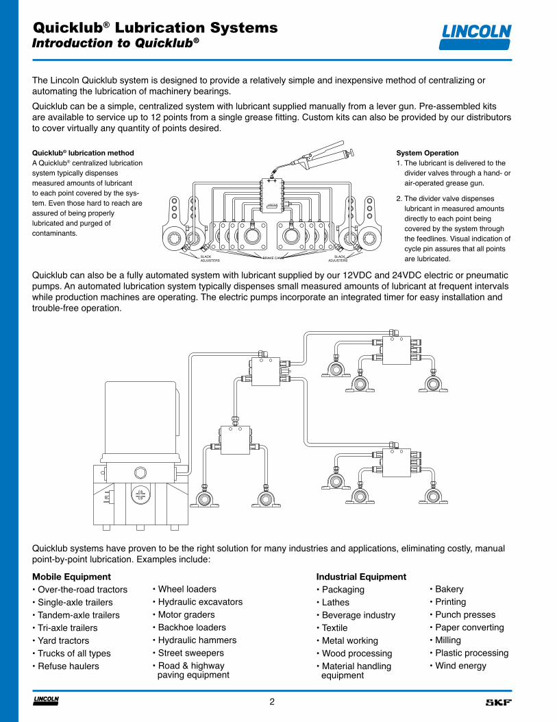
The Lincoln Quicklub system is designed to provide a relatively simple and inexpensive method of centralizing or automating the lubrication of machinery bearings.Quicklub can be a simple, centralized system with lubricant supplied manually from a lever gun. Pre-assembled kits are available to service up to 12 points from a single grease fitting. Custom kits can also be provided by our distributors to cover virtually any quantity of points desired.
Quicklub® lubrication methodA Quicklub® centralized lubrication system typically dispenses measured amounts of lubricant to each point covered by the sys-tem. Even those hard to reach are assured of being properly lubricated and purged of contaminants.
System Operation1. The lubricant is delivered to the
divider valves through a hand- or air-operated grease gun.
2. The divider valve dispenses lubricant in measured amounts directly to each point being covered by the system through the feedlines. Visual indication of cycle pin assures that all points are lubricated.
Quicklub can also be a fully automated system with lubricant supplied by our 12VDC and 24VDC electric or pneumatic pumps. An automated lubrication system typically dispenses small measured amounts of lubricant at frequent intervals while production machines are operating. The electric pumps incorporate an integrated timer for easy installation and trouble-free operation.
Quicklub systems have proven to be the right solution for many industries and applications, eliminating costly, manual point-by-point lubrication. Examples include:
LINCOLN
7
1
3
5
9
11
8
2
4
6
10
12
BRAKE CAMSSLACKADJUSTERS
SLACKADJUSTERS
Mobile Equipment• Over-the-road tractors• Single-axle trailers• Tandem-axle trailers• Tri-axle trailers• Yard tractors• Trucks of all types• Refuse haulers
• Wheel loaders• Hydraulic excavators• Motor graders• Backhoe loaders• Hydraulic hammers• Street sweepers• Road & highway paving equipment
• Bakery• Printing• Punch presses• Paper converting• Milling• Plastic processing• Wind energy
Industrial Equipment• Packaging• Lathes• Beverage industry• Textile• Metal working• Wood processing• Material handling equipment
Quicklub® Lubrication Systems
3
Introduction to Quicklub®
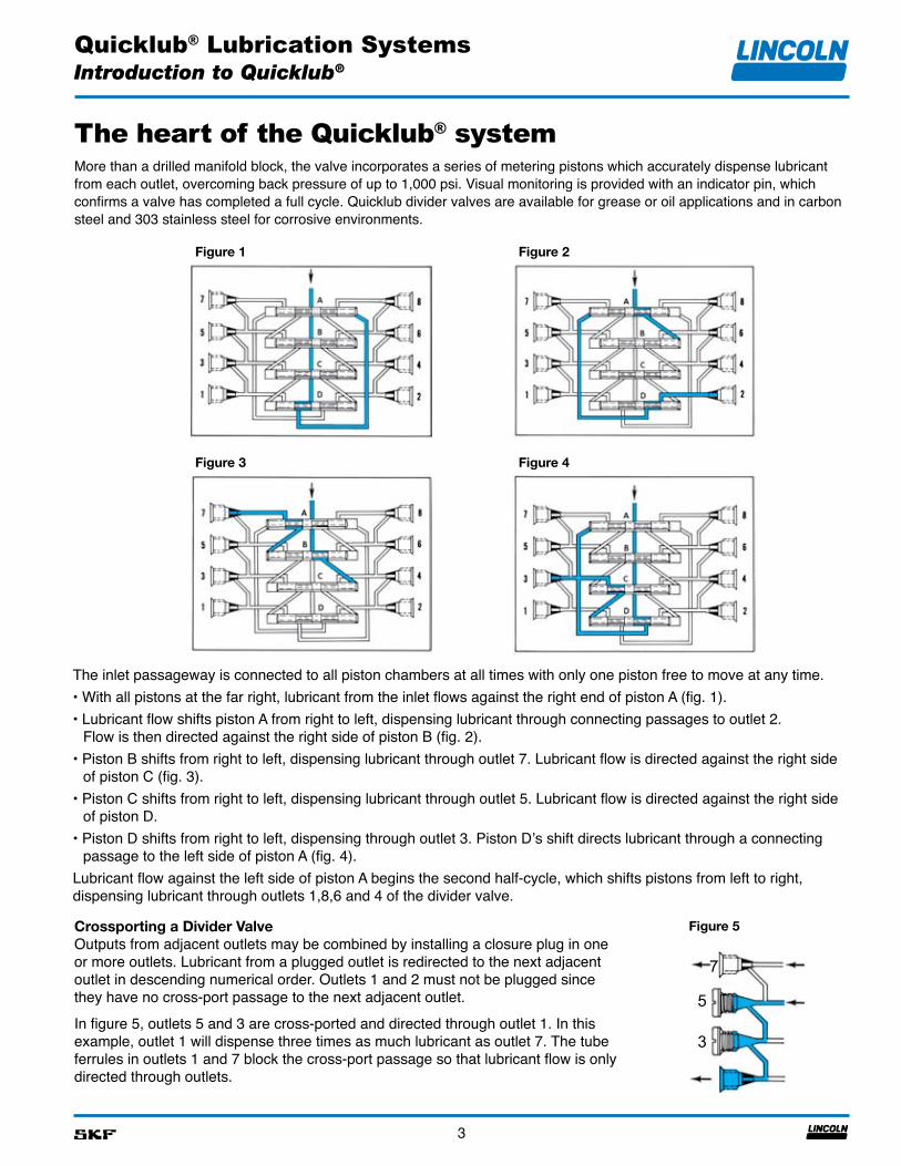
The heart of the Quicklub® systemMore than a drilled manifold block, the valve incorporates a series of metering pistons which accurately dispense lubricant from each outlet, overcoming back pressure of up to 1,000 psi. Visual monitoring is provided with an indicator pin, which confirms a valve has completed a full cycle. Quicklub divider valves are available for grease or oil applications and in carbon steel and 303 stainless steel for corrosive environments.
Figure 1 Figure 2
Figure 3 Figure 4
The inlet passageway is connected to all piston chambers at all times with only one piston free to move at any time.• With all pistons at the far right, lubricant from the inlet flows against the right end of piston A (fig. 1).• Lubricant flow shifts piston A from right to left, dispensing lubricant through connecting passages to outlet 2.
Flow is then directed against the right side of piston B (fig. 2).• Piston B shifts from right to left, dispensing lubricant through outlet 7. Lubricant flow is directed against the right side
of piston C (fig. 3).• Piston C shifts from right to left, dispensing lubricant through outlet 5. Lubricant flow is directed against the right side
of piston D.• Piston D shifts from right to left, dispensing through outlet 3. Piston D’s shift directs lubricant through a connecting
passage to the left side of piston A (fig. 4).Lubricant flow against the left side of piston A begins the second half-cycle, which shifts pistons from left to right, dispensing lubricant through outlets 1,8,6 and 4 of the divider valve.
Crossporting a Divider ValveOutputs from adjacent outlets may be combined by installing a closure plug in one or more outlets. Lubricant from a plugged outlet is redirected to the next adjacent outlet in descending numerical order. Outlets 1 and 2 must not be plugged since they have no cross-port passage to the next adjacent outlet.
In figure 5, outlets 5 and 3 are cross-ported and directed through outlet 1. In this example, outlet 1 will dispense three times as much lubricant as outlet 7. The tube ferrules in outlets 1 and 7 block the cross-port passage so that lubricant flow is only directed through outlets. 1
Figure 5
3
5
7
Quicklub® Lubrication Systems
4
Divider Valves
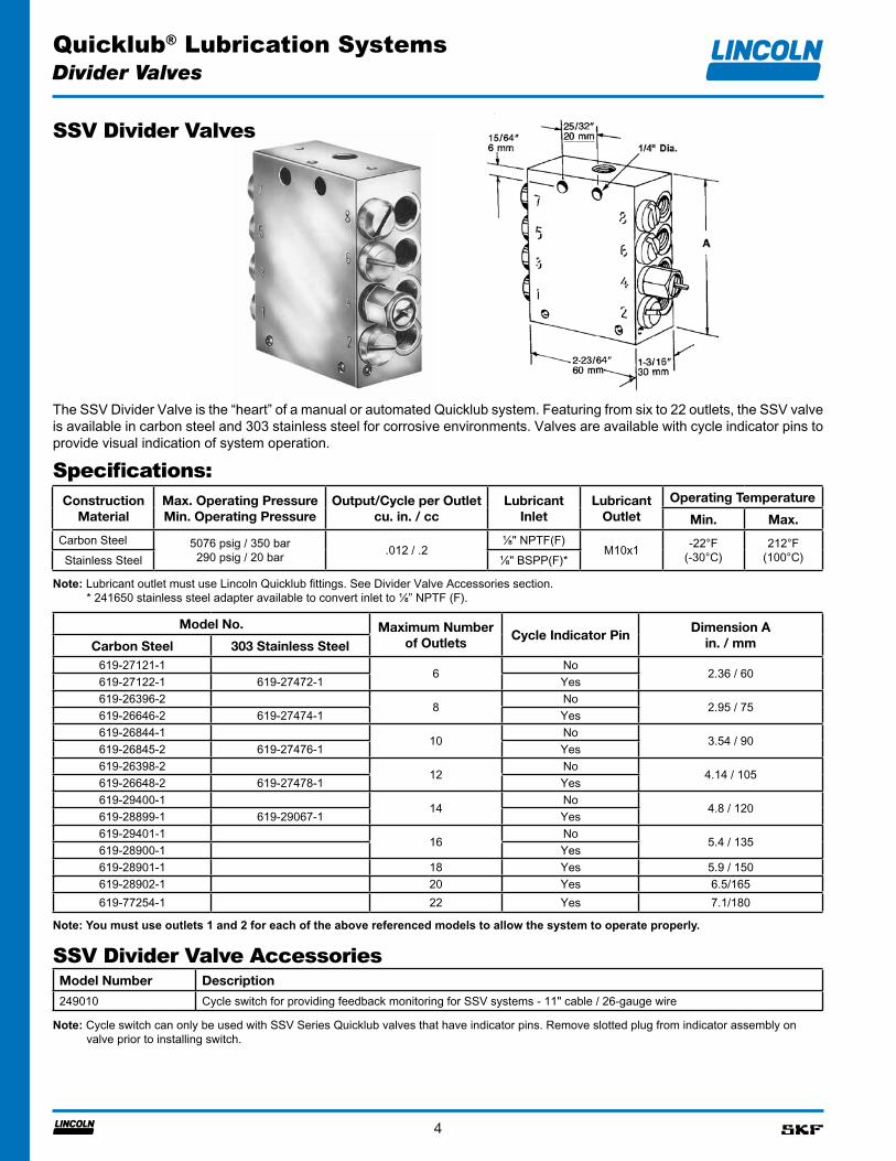
SSV Divider Valves
The SSV Divider Valve is the “heart” of a manual or automated Quicklub system. Featuring from six to 22 outlets, the SSV valve is available in carbon steel and 303 stainless steel for corrosive environments. Valves are available with cycle indicator pins to provide visual indication of system operation.
ConstructionMaterial
Max. Operating PressureMin. Operating Pressure
Output/Cycle per Outletcu. in. / cc
LubricantInlet
Lubricant Outlet
Operating Temperature
Min. Max.
Carbon Steel 5076 psig / 350 bar290 psig / 20 bar .012 / .2
⅛" NPTF(F)M10x1 -22°F
(-30°C)212°F
(100°C)Stainless Steel ⅛" BSPP(F)*
Specifications:
Model No. Maximum Number of Outlets
Cycle Indicator PinDimension A
in. / mmCarbon Steel 303 Stainless Steel619-27121-1
6No
2.36 / 60619-27122-1 619-27472-1 Yes619-26396-2
8No
2.95 / 75619-26646-2 619-27474-1 Yes619-26844-1
10No
3.54 / 90619-26845-2 619-27476-1 Yes619-26398-2
12No
4.14 / 105619-26648-2 619-27478-1 Yes619-29400-1
14No
4.8 / 120619-28899-1 619-29067-1 Yes619-29401-1
16No
5.4 / 135619-28900-1 Yes619-28901-1 18 Yes 5.9 / 150619-28902-1 20 Yes 6.5/165619-77254-1 22 Yes 7.1/180
Model Number Description
249010 Cycle switch for providing feedback monitoring for SSV systems - 11" cable / 26-gauge wire
Note: Lubricant outlet must use Lincoln Quicklub fittings. See Divider Valve Accessories section. * 241650 stainless steel adapter available to convert inlet to ⅛” NPTF (F).
Note: You must use outlets 1 and 2 for each of the above referenced models to allow the system to operate properly.
Note: Cycle switch can only be used with SSV Series Quicklub valves that have indicator pins. Remove slotted plug from indicator assembly on valve prior to installing switch.
SSV Divider Valve Accessories
Quicklub® Lubrication Systems
5
Divider Valves
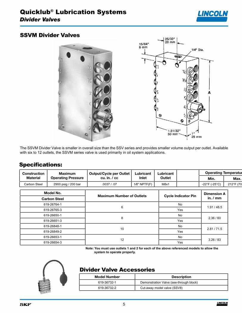
SSVM Divider Valves
Model No.Maximum Number of Outlets Cycle Indicator Pin
Dimension A in. / mmCarbon Steel
619-26764-16
No1.91 / 48.5
619-26765-3 Yes619-26650-1
8No
2.36 / 60619-26651-3 Yes619-26848-1
10No
2.81 / 71.5619-26849-2 Yes619-26653-1
12No
3.26 / 83619-26654-3 Yes
ConstructionMaterial
MaximumOperating Pressure
Output/Cycle per Outletcu. in. / cc
LubricantInlet
Lubricant Outlet
Operating Temperature
Min. Max.
Carbon Steel 2900 psig / 200 bar .0037 / .07 1⁄8" NPTF(F) M8x1 -22°F (-25°C) 212°F (70°C)
Specifications:
Model Number Description
619-36732-1 Demonstration Valve (see-through block)619-36732-2 Cut-away model valve (SSV8)
The SSVM Divider Valve is smaller in overall size than the SSV series and provides smaller volume output per outlet. Available with six to 12 outlets, the SSVM series valve is used primarily in oil system applications.
Note: You must use outlets 1 and 2 for each of the above referenced models to allow the system to operate properly.
Divider Valve Accessories
Quicklub® Lubrication Systems
6
Divider Valves
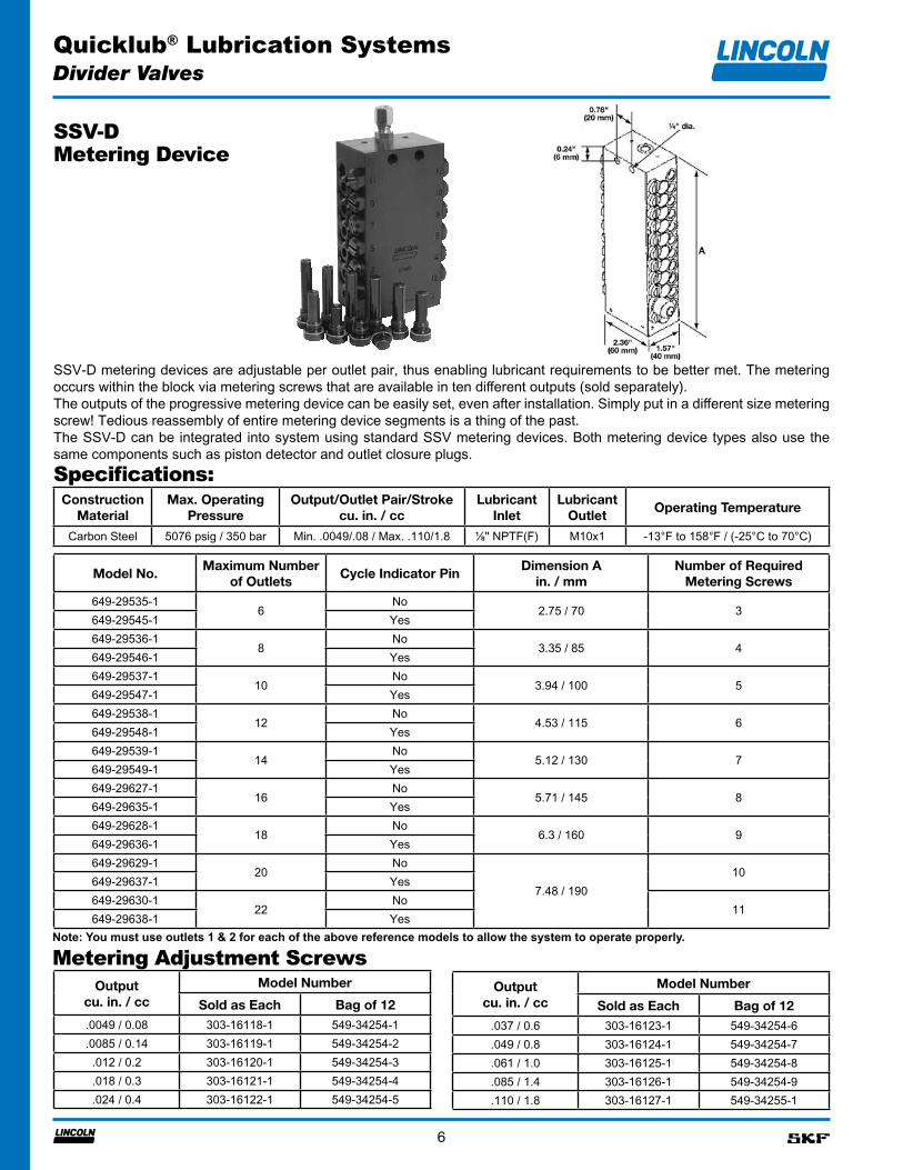
SSV-D
SSV-D metering devices are adjustable per outlet pair, thus enabling lubricant requirements to be better met. The metering occurs within the block via metering screws that are available in ten different outputs (sold separately).The outputs of the progressive metering device can be easily set, even after installation. Simply put in a different size metering screw! Tedious reassembly of entire metering device segments is a thing of the past.The SSV-D can be integrated into system using standard SSV metering devices. Both metering device types also use the same components such as piston detector and outlet closure plugs.
Model No.Maximum Number
of OutletsCycle Indicator Pin
Dimension A in. / mm
Number of Required Metering Screws
649-29535-16
No2.75 / 70 3
649-29545-1 Yes649-29536-1
8No
3.35 / 85 4649-29546-1 Yes649-29537-1
10No
3.94 / 100 5649-29547-1 Yes649-29538-1
12No
4.53 / 115 6649-29548-1 Yes649-29539-1
14No
5.12 / 130 7649-29549-1 Yes649-29627-1
16No
5.71 / 145 8649-29635-1 Yes649-29628-1
18No
6.3 / 160 9649-29636-1 Yes649-29629-1
20No
7.48 / 19010
649-29637-1 Yes649-29630-1
22No
11649-29638-1 Yes
Output cu. in. / cc
Model Number
Sold as Each Bag of 12.0049 / 0.08 303-16118-1 549-34254-1.0085 / 0.14 303-16119-1 549-34254-2.012 / 0.2 303-16120-1 549-34254-3.018 / 0.3 303-16121-1 549-34254-4.024 / 0.4 303-16122-1 549-34254-5
Output cu. in. / cc
Model Number
Sold as Each Bag of 12.037 / 0.6 303-16123-1 549-34254-6.049 / 0.8 303-16124-1 549-34254-7.061 / 1.0 303-16125-1 549-34254-8.085 / 1.4 303-16126-1 549-34254-9.110 / 1.8 303-16127-1 549-34255-1
ConstructionMaterial
Max. OperatingPressure
Output/Outlet Pair/Strokecu. in. / cc
LubricantInlet
Lubricant Outlet
Operating Temperature
Carbon Steel 5076 psig / 350 bar Min. .0049/.08 / Max. .110/1.8 ⅛" NPTF(F) M10x1 -13°F to 158°F / (-25°C to 70°C)
Specifications:
Metering Device
Note: You must use outlets 1 & 2 for each of the above reference models to allow the system to operate properly.
Metering Adjustment Screws
Quicklub® Lubrication Systems
7
Divider Valves
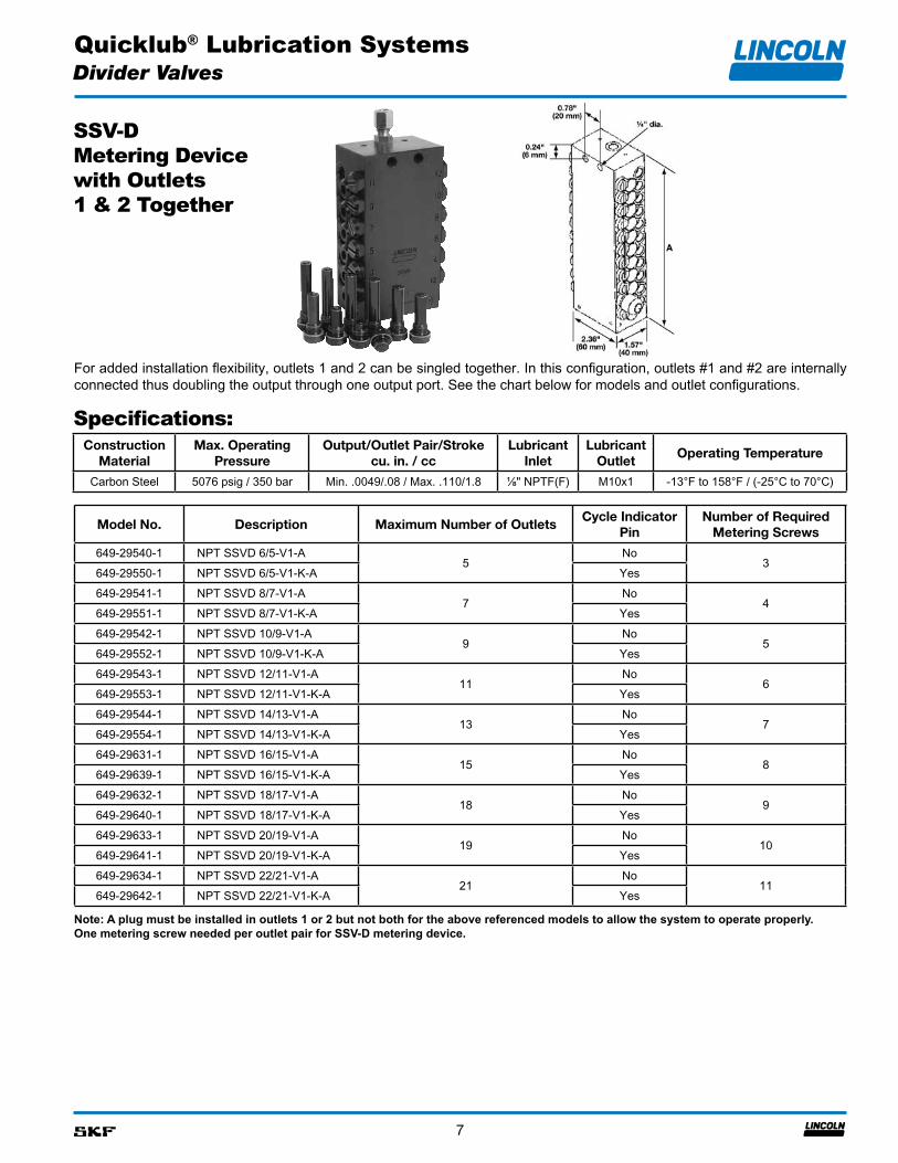
SSV-D Metering Device with Outlets 1 & 2 Together
For added installation flexibility, outlets 1 and 2 can be singled together. In this configuration, outlets #1 and #2 are internally connected thus doubling the output through one output port. See the chart below for models and outlet configurations.
ConstructionMaterial
Max. OperatingPressure
Output/Outlet Pair/Strokecu. in. / cc
LubricantInlet
Lubricant Outlet
Operating Temperature
Carbon Steel 5076 psig / 350 bar Min. .0049/.08 / Max. .110/1.8 ⅛" NPTF(F) M10x1 -13°F to 158°F / (-25°C to 70°C)
Specifications:
Note: A plug must be installed in outlets 1 or 2 but not both for the above referenced models to allow the system to operate properly.One metering screw needed per outlet pair for SSV-D metering device.
Model No. Description Maximum Number of OutletsCycle Indicator
PinNumber of Required
Metering Screws
649-29540-1 NPT SSVD 6/5-V1-A5
No3
649-29550-1 NPT SSVD 6/5-V1-K-A Yes649-29541-1 NPT SSVD 8/7-V1-A
7No
4649-29551-1 NPT SSVD 8/7-V1-K-A Yes649-29542-1 NPT SSVD 10/9-V1-A
9No
5649-29552-1 NPT SSVD 10/9-V1-K-A Yes649-29543-1 NPT SSVD 12/11-V1-A
11No
6649-29553-1 NPT SSVD 12/11-V1-K-A Yes649-29544-1 NPT SSVD 14/13-V1-A
13No
7649-29554-1 NPT SSVD 14/13-V1-K-A Yes649-29631-1 NPT SSVD 16/15-V1-A
15No
8649-29639-1 NPT SSVD 16/15-V1-K-A Yes649-29632-1 NPT SSVD 18/17-V1-A
18No
9649-29640-1 NPT SSVD 18/17-V1-K-A Yes649-29633-1 NPT SSVD 20/19-V1-A
19No
10649-29641-1 NPT SSVD 20/19-V1-K-A Yes649-29634-1 NPT SSVD 22/21-V1-A
21No
11649-29642-1 NPT SSVD 22/21-V1-K-A Yes

Quicklub® Lubrication Systems
8
Electric Grease Pumps—203 Series
P203 Series PumpThese pumps are electrically operated and are used in progressive-type automated lubrication systems. The proven and reliable P203 pump has been designed to develop high operating pressures allowing it to supply NLGI #2 grease in most ambient temperatures. Versatile, compact and ecomomical, this pump can be enhanced with several options including an integrated controller, low-level monitoring and system monitoring. Special configurations are available upon request.Note: Customer must furnish a 12- or 24-volt D.C. power source.
* Protected from water sprayed in all directions.** Single 6mm element standard; to increase pump output, add one or two additional element(s) #600-26876-2 and relief valve #270864.*** Pressure relief valve included with these models.
Model Specifications
* Can be set for either minutes or seconds.
Electric Grease Pumps Without Integrated ControllerModel Specifications
Model No. Electrical RequirementsReservoir Capacity
lb. kg. Liters
94224 24 VDC - 2 Amps4 1.8 2
94212 12 VDC - 3.5 Amps644-46278-3 24 VDC - 2 Amps 30 13.6 15
Electric Grease Pumps with Integrated On/Off ControllerOutput/Min Per Element**: .171 cu. in. / 2.8 cc
Lubricant Outlet: ⅛" NPT (F)
Max. System Operating Pressure: 5000 psig / 350 bar
Enclosure Rating: IP6K9K*
Operating Temperature Range: Min. -13°F / -25°C / Max. 158°F / 70°C
Reservoir Capacity: 2-, 4-, 8- or 15-liter ***
Reservoir Fill Method: By grease fitting
Pressure Relief Valve: 4000 psi, +/- 250 psi / 276 bar, +/- 17 bar
Model No.
Electrical Requirements
Interval Timer Setting Reservoir Capacity
On Time* (2 minute increments)
Off Time (1 hour increment) lb. kg. liter
Min Max Min Max
94012
12 VDC / 3.5 Amps
2 minutes 30 minutes 1 hour 15 hours
4 1.8 294412 8 3.6 494812 16 7.2 8
94412LDL 8 3.6 494812LDL 16 7.2 8
94024
24 VDC / 2 Amp
4 1.8 294424 8 3.6 494824 16 7.2 8
94824LDL 16 7.2 8644-46278-1 30 13.6 15
Quicklub® Lubrication Systems
9
Electric Grease Pumps—203 Series
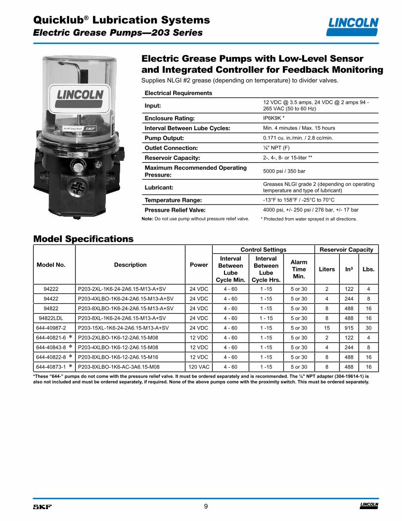
Electric Grease Pumps with Low-Level Sensor and Integrated Controller for Feedback Monitoring
Note: Do not use pump without pressure relief valve. * Protected from water sprayed in all directions.
Model Specifications
*These “644-” pumps do not come with the pressure relief valve. It must be ordered separately and is recommended. The ⅛" NPT adapter (304-19614-1) is also not included and must be ordered separately, if required. None of the above pumps come with the proximity switch. This must be ordered separately.
Supplies NLGI #2 grease (depending on temperature) to divider valves.
Electrical Requirements
Input:12 VDC @ 3.5 amps, 24 VDC @ 2 amps 94 - 265 VAC (50 to 60 Hz)
Enclosure Rating: IP6K9K *
Interval Between Lube Cycles: Min. 4 minutes / Max. 15 hours
Pump Output: 0.171 cu. in./min. / 2.8 cc/min.
Outlet Connection: ⅛" NPT (F)
Reservoir Capacity: 2-, 4-, 8- or 15-liter **
Maximum Recommended Operating Pressure:
5000 psi / 350 bar
Lubricant:Greases NLGI grade 2 (depending on operating temperature and type of lubricant)
Temperature Range: -13°F to 158°F / -25°C to 70°C
Pressure Relief Valve: 4000 psi, +/- 250 psi / 276 bar, +/- 17 bar
Model No. Description Power
Control Settings Reservoir Capacity
Interval Between
Lube Cycle Min.
Interval Between
Lube Cycle Hrs.
Alarm Time Min.
Liters In³ Lbs.
94222 P203-2XL-1K6-24-2A6.15-M13-A+SV 24 VDC 4 - 60 1 -15 5 or 30 2 122 4
94422 P203-4XLBO-1K6-24-2A6.15-M13-A+SV 24 VDC 4 - 60 1 -15 5 or 30 4 244 8
94822 P203-8XLBO-1K6-24-2A6.15-M13-A+SV 24 VDC 4 - 60 1 -15 5 or 30 8 488 16
94822LDL P203-8XL-1K6-24-2A6.15-M13-A+SV 24 VDC 4 - 60 1 - 15 5 or 30 8 488 16
644-40987-2 P203-15XL-1K6-24-2A6.15-M13-A+SV 24 VDC 4 - 60 1 -15 5 or 30 15 915 30
644-40821-6 * P203-2XLBO-1K6-12-2A6.15-M08 12 VDC 4 - 60 1 -15 5 or 30 2 122 4
644-40843-8 * P203-4XLBO-1K6-12-2A6.15-M08 12 VDC 4 - 60 1 -15 5 or 30 4 244 8
644-40822-8 * P203-8XLBO-1K6-12-2A6.15-M16 12 VDC 4 - 60 1 -15 5 or 30 8 488 16
644-40873-1 * P203-8XLBO-1K6-AC-3A6.15-M08 120 VAC 4 - 60 1 -15 5 or 30 8 488 16
Quicklub® Lubrication Systems
10
Electric Grease Pumps—203 Series
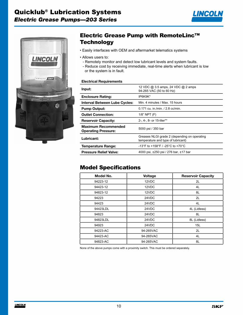
Electric Grease Pump with RemoteLinc™ Technology• Easily interfaces with OEM and aftermarket telematics systems
• Allows users to: - Remotely monitor and detect low lubricant levels and system faults. - Reduce cost by receiving immediate, real-time alerts when lubricant is low or the system is in fault.
Model SpecificationsModel No. Voltage Reservoir Capacity
94223-12 12VDC 2L94423-12 12VDC 4L94823-12 12VDC 8L94223 24VDC 2L94423 24VDC 4L94423LDL 24VDC 4L (Lidless)94823 24VDC 8L94823LDL 24VDC 8L (Lidless)94923 24VDC 15L94223-AC 94-265VAC 2L94423-AC 94-265VAC 4L94823-AC 94-265VAC 8L
Electrical Requirements
Input:12 VDC @ 3.5 amps, 24 VDC @ 2 amps94-265 VAC (50 to 60 Hz)
Enclosure Rating: IP6K9K*
Interval Between Lube Cycles: Min. 4 minutes / Max. 15 hours
Pump Output: 0.171 cu. in./min. / 2.8 cc/min.
Outlet Connection: 1/8” NPT (F)
Reservoir Capacity: 2-, 4-, 8- or 15-liter**
Maximum Recommended Operating Pressure:
5000 psi / 350 bar
Lubricant:Greases NLGI grade 2 (depending on operating temperature and type of lubricant)
Temperature Range: -13°F to +158°F / -25°C to +70°C
Pressure Relief Valve: 4000 psi, ±250 psi / 276 bar, ±17 bar
None of the above pumps come with a proximity switch. This must be ordered separately.
Quicklub® Lubrication Systems
11
Electric Grease Pumps—203 Series
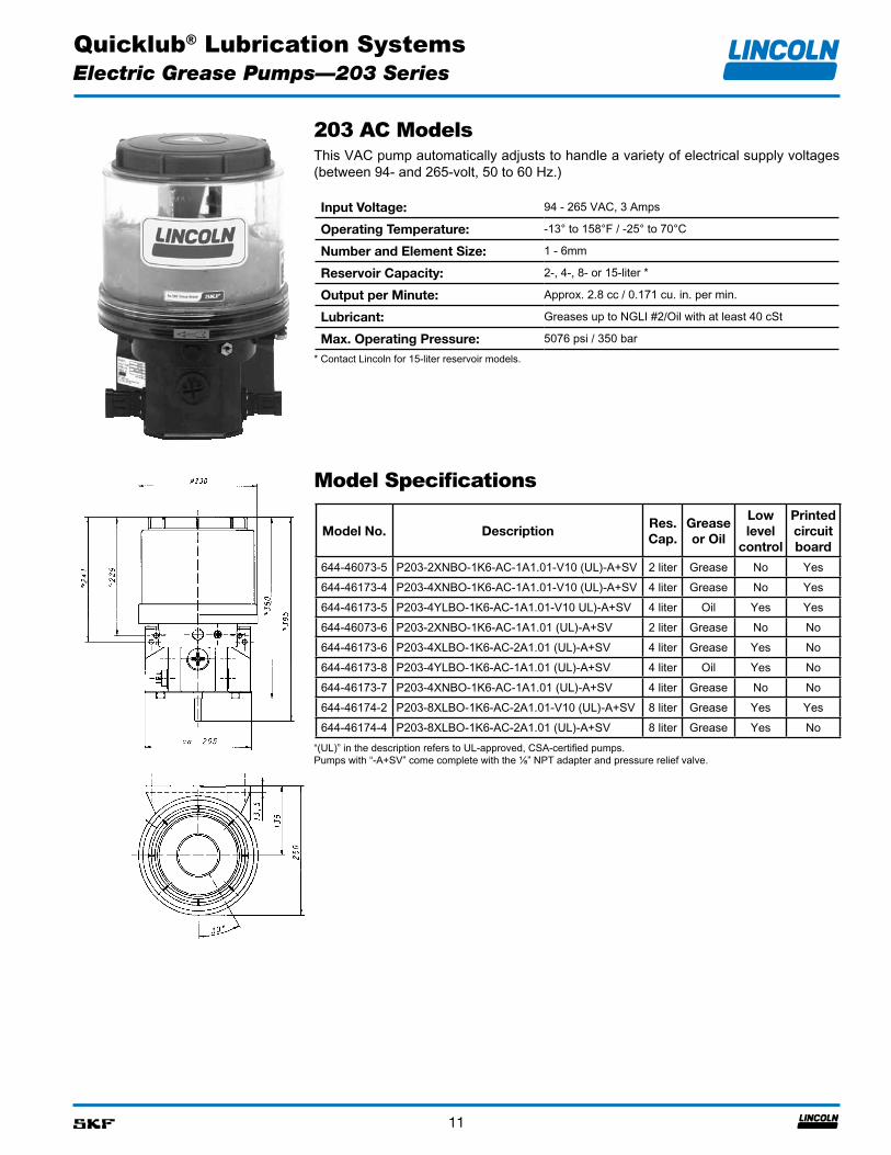
203 AC ModelsThis VAC pump automatically adjusts to handle a variety of electrical supply voltages (between 94- and 265-volt, 50 to 60 Hz.)
* Contact Lincoln for 15-liter reservoir models.
Model Specifications
“(UL)” in the description refers to UL-approved, CSA-certified pumps.Pumps with “-A+SV” come complete with the ⅛” NPT adapter and pressure relief valve.
Input Voltage: 94 - 265 VAC, 3 Amps
Operating Temperature: -13° to 158°F / -25° to 70°C
Number and Element Size: 1 - 6mm
Reservoir Capacity: 2-, 4-, 8- or 15-liter *
Output per Minute: Approx. 2.8 cc / 0.171 cu. in. per min.
Lubricant: Greases up to NGLI #2/Oil with at least 40 cSt
Max. Operating Pressure: 5076 psi / 350 bar
Model No. DescriptionRes.Cap.
Grease or Oil
Low level
control
Printed circuit board
644-46073-5 P203-2XNBO-1K6-AC-1A1.01-V10 (UL)-A+SV 2 liter Grease No Yes644-46173-4 P203-4XNBO-1K6-AC-1A1.01-V10 (UL)-A+SV 4 liter Grease No Yes644-46173-5 P203-4YLBO-1K6-AC-1A1.01-V10 UL)-A+SV 4 liter Oil Yes Yes644-46073-6 P203-2XNBO-1K6-AC-1A1.01 (UL)-A+SV 2 liter Grease No No644-46173-6 P203-4XLBO-1K6-AC-2A1.01 (UL)-A+SV 4 liter Grease Yes No644-46173-8 P203-4YLBO-1K6-AC-1A1.01 (UL)-A+SV 4 liter Oil Yes No644-46173-7 P203-4XNBO-1K6-AC-1A1.01 (UL)-A+SV 4 liter Grease No No644-46174-2 P203-8XLBO-1K6-AC-2A1.01-V10 (UL)-A+SV 8 liter Grease Yes Yes644-46174-4 P203-8XLBO-1K6-AC-2A1.01 (UL)-A+SV 8 liter Grease Yes No
Quicklub® Lubrication Systems
12
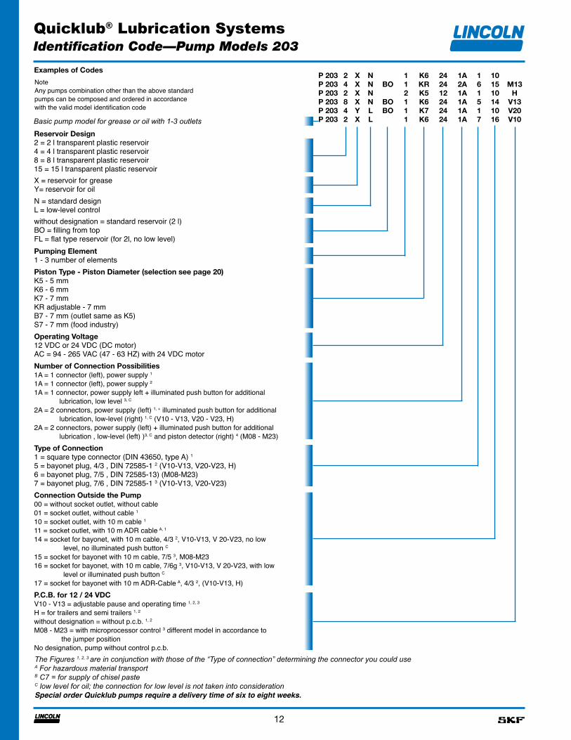
P 203P 203P 203P 203P 203P 203
242842
XXXXYX
NNNNLL
BO
BOBO
112111
K6KRK5K6K7K6
242412242424
1A2A1A1A1A1A
161517
101510141016
M13H
V13V20V10
Reservoir Design2 = 2 l transparent plastic reservoir4 = 4 l transparent plastic reservoir8 = 8 l transparent plastic reservoir15 = 15 l transparent plastic reservoirX = reservoir for greaseY= reservoir for oilN = standard designL = low-level controlwithout designation = standard reservoir (2 l)BO = filling from topFL = flat type reservoir (for 2l, no low level)Pumping Element1 - 3 number of elementsPiston Type - Piston Diameter (selection see page 20)K5 - 5 mmK6 - 6 mmK7 - 7 mmKR adjustable - 7 mmB7 - 7 mm (outlet same as K5)S7 - 7 mm (food industry)Operating Voltage12 VDC or 24 VDC (DC motor)AC = 94 - 265 VAC (47 - 63 HZ) with 24 VDC motorNumber of Connection Possibilities1A = 1 connector (left), power supply 1
1A = 1 connector (left), power supply 2
1A = 1 connector, power supply left + illuminated push button for additional lubrication, low level 3, C
2A = 2 connectors, power supply (left) 1, + illuminated push button for additional lubrication, low-level (right) 1, C (V10 - V13, V20 - V23, H)2A = 2 connectors, power supply (left) + illuminated push button for additional lubrication , low-level (left) )3, C and piston detector (right) 4 (M08 - M23)Type of Connection1 = square type connector (DIN 43650, type A) 1
5 = bayonet plug, 4/3 , DIN 72585-1 2 (V10-V13, V20-V23, H)6 = bayonet plug, 7/5 , DIN 72585-13) (M08-M23)7 = bayonet plug, 7/6 , DIN 72585-1 3 (V10-V13, V20-V23)Connection Outside the Pump00 = without socket outlet, without cable01 = socket outlet, without cable 1
10 = socket outlet, with 10 m cable 1
11 = socket outlet, with 10 m ADR cable A, 1
14 = socket for bayonet, with 10 m cable, 4/3 2, V10-V13, V 20-V23, no low level, no illuminated push button C
15 = socket for bayonet with 10 m cable, 7/5 3, M08-M2316 = socket for bayonet, with 10 m cable, 7/6g 3, V10-V13, V 20-V23, with low level or illuminated push button C
17 = socket for bayonet with 10 m ADR-Cable A, 4/3 2, (V10-V13, H)P.C.B. for 12 / 24 VDCV10 - V13 = adjustable pause and operating time 1, 2, 3
H = for trailers and semi trailers 1, 2
without designation = without p.c.b. 1, 2
M08 - M23 = with microprocessor control 3 different model in accordance to the jumper positionNo designation, pump without control p.c.b.
Examples of Codes
NoteAny pumps combination other than the above standardpumps can be composed and ordered in accordancewith the valid model identification code
The Figures 1, 2, 3 are in conjunction with those of the “Type of connection” determining the connector you could useA For hazardous material transportB C7 = for supply of chisel pasteC low level for oil; the connection for low level is not taken into considerationSpecial order Quicklub pumps require a delivery time of six to eight weeks.
Basic pump model for grease or oil with 1-3 outlets
Identification Code—Pump Models 203
Quicklub® Lubrication Systems
13
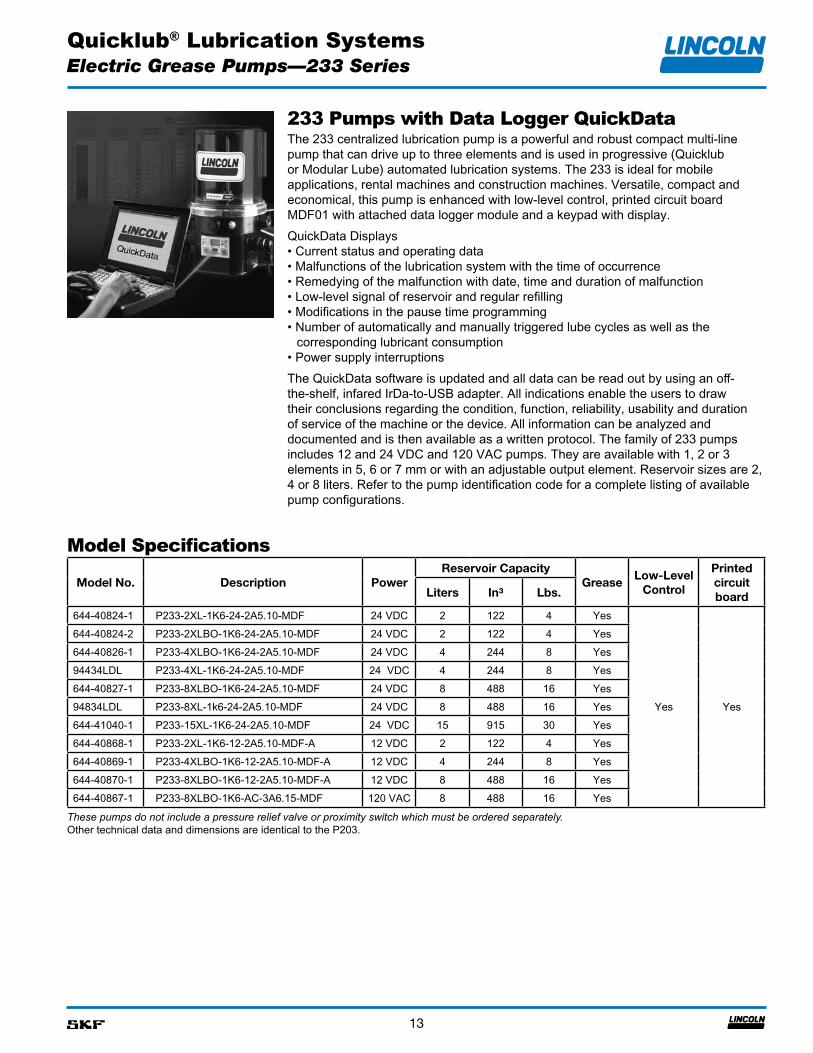
233 Pumps with Data Logger QuickData
Electric Grease Pumps—233 Series
The 233 centralized lubrication pump is a powerful and robust compact multi-line pump that can drive up to three elements and is used in progressive (Quicklub or Modular Lube) automated lubrication systems. The 233 is ideal for mobile applications, rental machines and construction machines. Versatile, compact and economical, this pump is enhanced with low-level control, printed circuit board MDF01 with attached data logger module and a keypad with display.QuickData Displays• Current status and operating data• Malfunctions of the lubrication system with the time of occurrence• Remedying of the malfunction with date, time and duration of malfunction• Low-level signal of reservoir and regular refilling• Modifications in the pause time programming• Number of automatically and manually triggered lube cycles as well as the
corresponding lubricant consumption• Power supply interruptionsThe QuickData software is updated and all data can be read out by using an off-the-shelf, infared IrDa-to-USB adapter. All indications enable the users to draw their conclusions regarding the condition, function, reliability, usability and duration of service of the machine or the device. All information can be analyzed and documented and is then available as a written protocol. The family of 233 pumps includes 12 and 24 VDC and 120 VAC pumps. They are available with 1, 2 or 3 elements in 5, 6 or 7 mm or with an adjustable output element. Reservoir sizes are 2, 4 or 8 liters. Refer to the pump identification code for a complete listing of available pump configurations.
Model Specifications
These pumps do not include a pressure relief valve or proximity switch which must be ordered separately.Other technical data and dimensions are identical to the P203.
Model No. Description PowerReservoir Capacity
GreaseLow-Level
Control
Printed circuit boardLiters In³ Lbs.
644-40824-1 P233-2XL-1K6-24-2A5.10-MDF 24 VDC 2 122 4 Yes
Yes Yes
644-40824-2 P233-2XLBO-1K6-24-2A5.10-MDF 24 VDC 2 122 4 Yes644-40826-1 P233-4XLBO-1K6-24-2A5.10-MDF 24 VDC 4 244 8 Yes94434LDL P233-4XL-1K6-24-2A5.10-MDF 24 VDC 4 244 8 Yes644-40827-1 P233-8XLBO-1K6-24-2A5.10-MDF 24 VDC 8 488 16 Yes94834LDL P233-8XL-1k6-24-2A5.10-MDF 24 VDC 8 488 16 Yes644-41040-1 P233-15XL-1K6-24-2A5.10-MDF 24 VDC 15 915 30 Yes644-40868-1 P233-2XL-1K6-12-2A5.10-MDF-A 12 VDC 2 122 4 Yes644-40869-1 P233-4XLBO-1K6-12-2A5.10-MDF-A 12 VDC 4 244 8 Yes644-40870-1 P233-8XLBO-1K6-12-2A5.10-MDF-A 12 VDC 8 488 16 Yes644-40867-1 P233-8XLBO-1K6-AC-3A6.15-MDF 120 VAC 8 488 16 Yes
Quicklub® Lubrication Systems
14
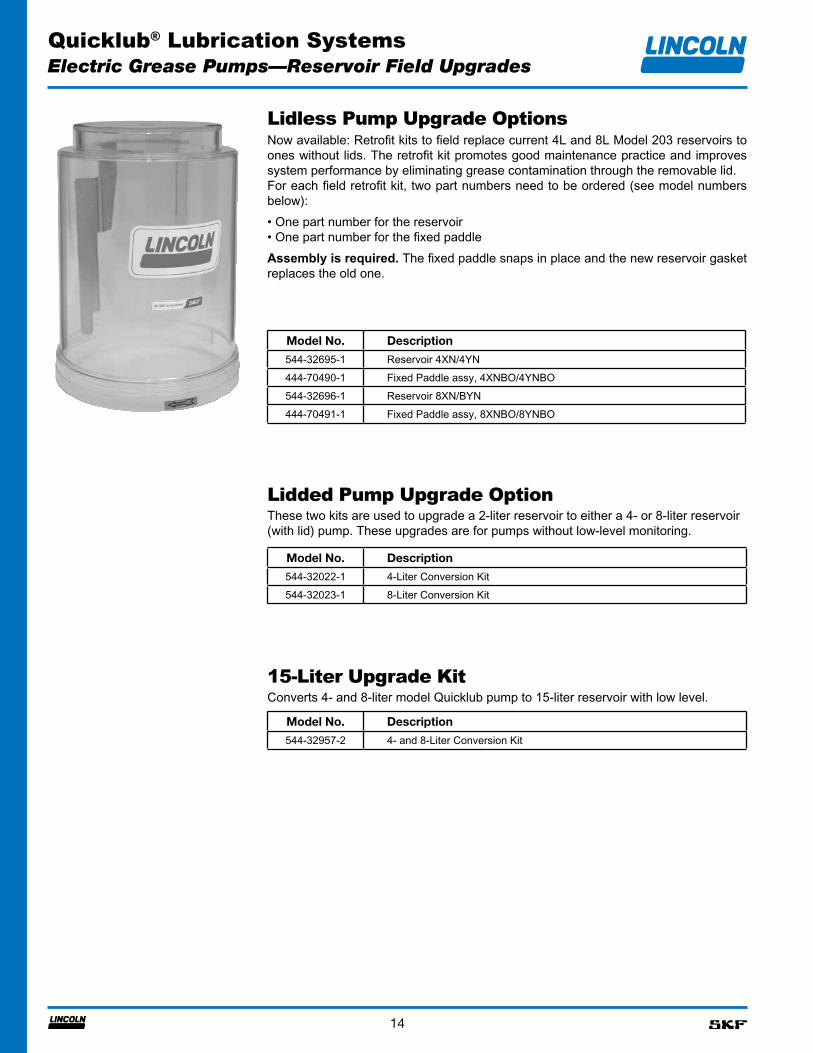
Electric Grease Pumps—Reservoir Field Upgrades
Lidless Pump Upgrade OptionsNow available: Retrofit kits to field replace current 4L and 8L Model 203 reservoirs to ones without lids. The retrofit kit promotes good maintenance practice and improves system performance by eliminating grease contamination through the removable lid.For each field retrofit kit, two part numbers need to be ordered (see model numbers below):• One part number for the reservoir• One part number for the fixed paddle Assembly is required. The fixed paddle snaps in place and the new reservoir gasket replaces the old one.
Lidded Pump Upgrade OptionThese two kits are used to upgrade a 2-liter reservoir to either a 4- or 8-liter reservoir (with lid) pump. These upgrades are for pumps without low-level monitoring.
Model No. Description
544-32695-1 Reservoir 4XN/4YN444-70490-1 Fixed Paddle assy, 4XNBO/4YNBO544-32696-1 Reservoir 8XN/BYN444-70491-1 Fixed Paddle assy, 8XNBO/8YNBO
Model No. Description
544-32022-1 4-Liter Conversion Kit544-32023-1 8-Liter Conversion Kit
15-Liter Upgrade KitConverts 4- and 8-liter model Quicklub pump to 15-liter reservoir with low level.
Model No. Description
544-32957-2 4- and 8-Liter Conversion Kit
Quicklub® Lubrication Systems
15
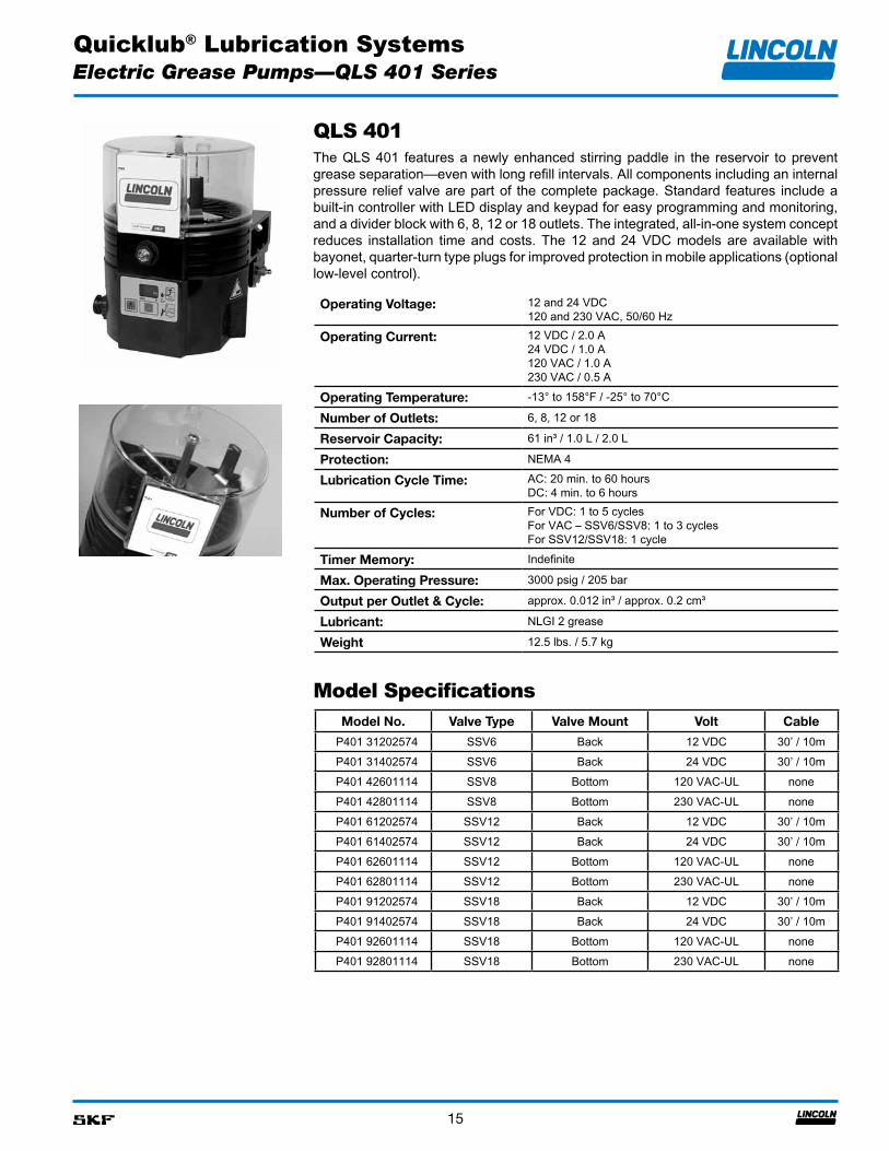
QLS 401The QLS 401 features a newly enhanced stirring paddle in the reservoir to prevent grease separation—even with long refill intervals. All components including an internal pressure relief valve are part of the complete package. Standard features include a built-in controller with LED display and keypad for easy programming and monitoring, and a divider block with 6, 8, 12 or 18 outlets. The integrated, all-in-one system concept reduces installation time and costs. The 12 and 24 VDC models are available with bayonet, quarter-turn type plugs for improved protection in mobile applications (optional low-level control).
Operating Voltage: 12 and 24 VDC120 and 230 VAC, 50/60 Hz
Operating Current: 12 VDC / 2.0 A24 VDC / 1.0 A120 VAC / 1.0 A230 VAC / 0.5 A
Operating Temperature: -13° to 158°F / -25° to 70°C
Number of Outlets: 6, 8, 12 or 18
Reservoir Capacity: 61 in³ / 1.0 L / 2.0 L
Protection: NEMA 4
Lubrication Cycle Time: AC: 20 min. to 60 hoursDC: 4 min. to 6 hours
Number of Cycles: For VDC: 1 to 5 cyclesFor VAC – SSV6/SSV8: 1 to 3 cyclesFor SSV12/SSV18: 1 cycle
Timer Memory: Indefinite
Max. Operating Pressure: 3000 psig / 205 bar
Output per Outlet & Cycle: approx. 0.012 in³ / approx. 0.2 cm³
Lubricant: NLGI 2 grease
Weight 12.5 lbs. / 5.7 kg
Model Specifications
Electric Grease Pumps—QLS 401 Series
Model No. Valve Type Valve Mount Volt Cable
P401 31202574 SSV6 Back 12 VDC 30’ / 10mP401 31402574 SSV6 Back 24 VDC 30’ / 10mP401 42601114 SSV8 Bottom 120 VAC-UL noneP401 42801114 SSV8 Bottom 230 VAC-UL noneP401 61202574 SSV12 Back 12 VDC 30’ / 10mP401 61402574 SSV12 Back 24 VDC 30’ / 10mP401 62601114 SSV12 Bottom 120 VAC-UL noneP401 62801114 SSV12 Bottom 230 VAC-UL noneP401 91202574 SSV18 Back 12 VDC 30’ / 10mP401 91402574 SSV18 Back 24 VDC 30’ / 10mP401 92601114 SSV18 Bottom 120 VAC-UL noneP401 92801114 SSV18 Bottom 230 VAC-UL none
Quicklub® Lubrication Systems
16
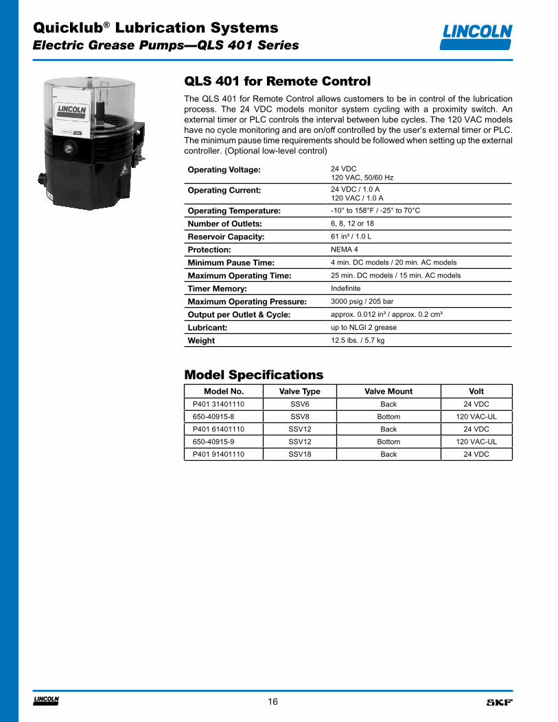
QLS 401 for Remote ControlThe QLS 401 for Remote Control allows customers to be in control of the lubrication process. The 24 VDC models monitor system cycling with a proximity switch. An external timer or PLC controls the interval between lube cycles. The 120 VAC models have no cycle monitoring and are on/off controlled by the user’s external timer or PLC. The minimum pause time requirements should be followed when setting up the external controller. (Optional low-level control)
Operating Voltage: 24 VDC120 VAC, 50/60 Hz
Operating Current: 24 VDC / 1.0 A120 VAC / 1.0 A
Operating Temperature: -10° to 158°F / -25° to 70°C
Number of Outlets: 6, 8, 12 or 18
Reservoir Capacity: 61 in³ / 1.0 L
Protection: NEMA 4
Minimum Pause Time: 4 min. DC models / 20 min. AC models
Maximum Operating Time: 25 min. DC models / 15 min. AC models
Timer Memory: Indefinite
Maximum Operating Pressure: 3000 psig / 205 bar
Output per Outlet & Cycle: approx. 0.012 in³ / approx. 0.2 cm³
Lubricant: up to NLGI 2 grease
Weight 12.5 lbs. / 5.7 kg
Model SpecificationsModel No. Valve Type Valve Mount Volt
P401 31401110 SSV6 Back 24 VDC650-40915-8 SSV8 Bottom 120 VAC-ULP401 61401110 SSV12 Back 24 VDC650-40915-9 SSV12 Bottom 120 VAC-ULP401 91401110 SSV18 Back 24 VDC
Electric Grease Pumps—QLS 401 Series
Quicklub® Lubrication Systems
17
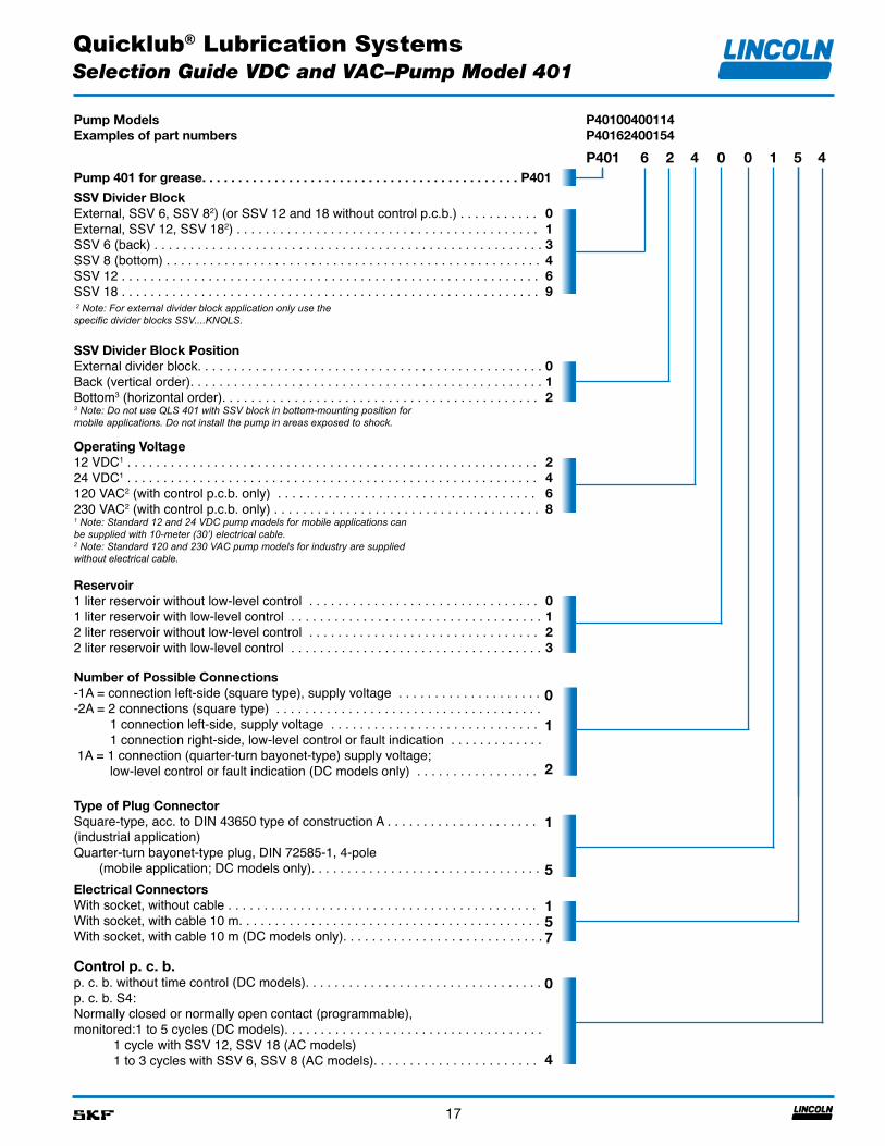
Pump ModelsExamples of part numbers
P40100400114P40162400154
P401 6 2 4 0 0 1 5 4Pump 401 for grease. . . . . . . . . . . . . . . . . . . . . . . . . . . . . . . . . . . . . . . . . . . . P401
SSV Divider BlockExternal, SSV 6, SSV 82) (or SSV 12 and 18 without control p.c.b.) . . . . . . . . . . . External, SSV 12, SSV 182) . . . . . . . . . . . . . . . . . . . . . . . . . . . . . . . . . . . . . . . . . . SSV 6 (back) . . . . . . . . . . . . . . . . . . . . . . . . . . . . . . . . . . . . . . . . . . . . . . . . . . . . . .SSV 8 (bottom) . . . . . . . . . . . . . . . . . . . . . . . . . . . . . . . . . . . . . . . . . . . . . . . . . . . . SSV 12 . . . . . . . . . . . . . . . . . . . . . . . . . . . . . . . . . . . . . . . . . . . . . . . . . . . . . . . . . . SSV 18 . . . . . . . . . . . . . . . . . . . . . . . . . . . . . . . . . . . . . . . . . . . . . . . . . . . . . . . . . . 2 Note: For external divider block application only use the specific divider blocks SSV....KNQLS.
013469
SSV Divider Block PositionExternal divider block. . . . . . . . . . . . . . . . . . . . . . . . . . . . . . . . . . . . . . . . . . . . . . . . Back (vertical order). . . . . . . . . . . . . . . . . . . . . . . . . . . . . . . . . . . . . . . . . . . . . . . . . Bottom3 (horizontal order). . . . . . . . . . . . . . . . . . . . . . . . . . . . . . . . . . . . . . . . . . . . 3 Note: Do not use QLS 401 with SSV block in bottom-mounting position formobile applications. Do not install the pump in areas exposed to shock.
012
Operating Voltage12 VDC1 . . . . . . . . . . . . . . . . . . . . . . . . . . . . . . . . . . . . . . . . . . . . . . . . . . . . . . . . . 24 VDC1 . . . . . . . . . . . . . . . . . . . . . . . . . . . . . . . . . . . . . . . . . . . . . . . . . . . . . . . . . 120 VAC2 (with control p.c.b. only) . . . . . . . . . . . . . . . . . . . . . . . . . . . . . . . . . . . . 230 VAC2 (with control p.c.b. only) . . . . . . . . . . . . . . . . . . . . . . . . . . . . . . . . . . . . .1 Note: Standard 12 and 24 VDC pump models for mobile applications canbe supplied with 10-meter (30’) electrical cable.2 Note: Standard 120 and 230 VAC pump models for industry are suppliedwithout electrical cable.
2468
Reservoir1 liter reservoir without low-level control . . . . . . . . . . . . . . . . . . . . . . . . . . . . . . . . 1 liter reservoir with low-level control . . . . . . . . . . . . . . . . . . . . . . . . . . . . . . . . . . .2 liter reservoir without low-level control . . . . . . . . . . . . . . . . . . . . . . . . . . . . . . . . 2 liter reservoir with low-level control . . . . . . . . . . . . . . . . . . . . . . . . . . . . . . . . . . .
0123
Number of Possible Connections-1A = connection left-side (square type), supply voltage . . . . . . . . . . . . . . . . . . . . -2A = 2 connections (square type) . . . . . . . . . . . . . . . . . . . . . . . . . . . . . . . . . . . . . 1 connection left-side, supply voltage . . . . . . . . . . . . . . . . . . . . . . . . . . . . . 1 connection right-side, low-level control or fault indication . . . . . . . . . . . . . 1A = 1 connection (quarter-turn bayonet-type) supply voltage; low-level control or fault indication (DC models only) . . . . . . . . . . . . . . . . .
0
1
2
Type of Plug ConnectorSquare-type, acc. to DIN 43650 type of construction A . . . . . . . . . . . . . . . . . . . . . (industrial application)Quarter-turn bayonet-type plug, DIN 72585-1, 4-pole (mobile application; DC models only). . . . . . . . . . . . . . . . . . . . . . . . . . . . . . . .
1
5Electrical ConnectorsWith socket, without cable . . . . . . . . . . . . . . . . . . . . . . . . . . . . . . . . . . . . . . . . . . . With socket, with cable 10 m. . . . . . . . . . . . . . . . . . . . . . . . . . . . . . . . . . . . . . . . . . With socket, with cable 10 m (DC models only). . . . . . . . . . . . . . . . . . . . . . . . . . . .
157
Control p. c. b.p. c. b. without time control (DC models). . . . . . . . . . . . . . . . . . . . . . . . . . . . . . . . .p. c. b. S4:Normally closed or normally open contact (programmable),monitored:1 to 5 cycles (DC models). . . . . . . . . . . . . . . . . . . . . . . . . . . . . . . . . . . . 1 cycle with SSV 12, SSV 18 (AC models) 1 to 3 cycles with SSV 6, SSV 8 (AC models). . . . . . . . . . . . . . . . . . . . . . .
0
4
Selection Guide VDC and VAC–Pump Model 401
Quicklub® Lubrication Systems
18
Electric Grease Pumps—QLS 301 Series
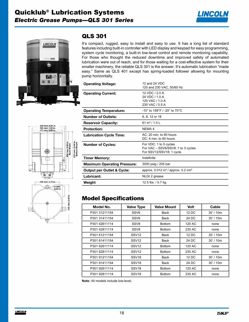
QLS 301It’s compact, rugged, easy to install and easy to use. It has a long list of standard features including built-in controller with LED display and keypad for easy programming, system cycle monitoring, a built-in low-level control and remote monitoring capability. For those who thought the reduced downtime and improved safety of automated lubrication were out of reach, and for those waiting for a cost-effective system for their smaller machinery, the reliable QLS 301 is the answer. It’s automatic lubrication “made easy.” Same as QLS 401 except has spring-loaded follower allowing for mounting pump horizontally.
Operating Voltage: 12 and 24 VDC120 and 230 VAC, 50/60 Hz
Operating Current: 12 VDC / 2.0 A24 VDC / 1.0 A120 VAC / 1.0 A230 VAC / 0.5 A
Operating Temperature: -10° to 158°F / -25° to 70°C
Number of Outlets: 6, 8, 12 or 18
Reservoir Capacity: 61 in³ / 1.0 L
Protection: NEMA 4
Lubrication Cycle Time: AC: 20 min. to 60 hoursDC: 4 min. to 60 hours
Number of Cycles: For VDC: 1 to 5 cyclesFor VAC – SSV6/SSV8: 1 to 3 cyclesFor SSV12/SSV18: 1 cycle
Timer Memory: Indefinite
Maximum Operating Pressure: 3000 psig / 205 bar
Output per Outlet & Cycle: approx. 0.012 in³ / approx. 0.2 cm³
Lubricant: NLGI 2 grease
Weight 12.5 lbs. / 5.7 kg
Model SpecificationsModel No. Valve Type Valve Mount Volt Cable
P301 31211154 SSV6 Back 12 DC 30’ / 10mP301 31411154 SSV6 Back 24 DC 30’ / 10mP301 42611114 SSV8 Bottom 120 AC noneP301 42811114 SSV8 Bottom 230 AC noneP301 61211154 SSV12 Back 12 DC 30’ / 10mP301 61411154 SSV12 Back 24 DC 30’ / 10mP301 62611114 SSV12 Bottom 120 AC noneP301 62811114 SSV12 Bottom 230 AC noneP301 91211154 SSV18 Back 12 DC 30’ / 10mP301 91411154 SSV18 Back 24 DC 30’ / 10mP301 92611114 SSV18 Bottom 120 AC noneP301 92811114 SSV18 Bottom 230 AC none
Note: All models include low-level.
Quicklub® Lubrication Systems
19
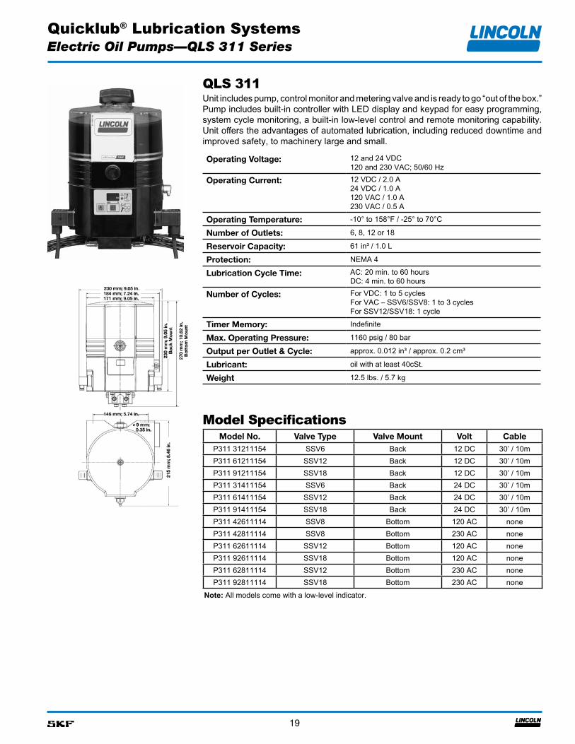
QLS 311Unit includes pump, control monitor and metering valve and is ready to go “out of the box.” Pump includes built-in controller with LED display and keypad for easy programming, system cycle monitoring, a built-in low-level control and remote monitoring capability. Unit offers the advantages of automated lubrication, including reduced downtime and improved safety, to machinery large and small.
Operating Voltage: 12 and 24 VDC120 and 230 VAC; 50/60 Hz
Operating Current: 12 VDC / 2.0 A24 VDC / 1.0 A120 VAC / 1.0 A230 VAC / 0.5 A
Operating Temperature: -10° to 158°F / -25° to 70°C
Number of Outlets: 6, 8, 12 or 18
Reservoir Capacity: 61 in³ / 1.0 L
Protection: NEMA 4
Lubrication Cycle Time: AC: 20 min. to 60 hoursDC: 4 min. to 60 hours
Number of Cycles: For VDC: 1 to 5 cyclesFor VAC – SSV6/SSV8: 1 to 3 cyclesFor SSV12/SSV18: 1 cycle
Timer Memory: Indefinite
Max. Operating Pressure: 1160 psig / 80 bar
Output per Outlet & Cycle: approx. 0.012 in³ / approx. 0.2 cm³
Lubricant: oil with at least 40cSt.
Weight 12.5 lbs. / 5.7 kg
Model SpecificationsModel No. Valve Type Valve Mount Volt Cable
P311 31211154 SSV6 Back 12 DC 30’ / 10mP311 61211154 SSV12 Back 12 DC 30’ / 10mP311 91211154 SSV18 Back 12 DC 30’ / 10mP311 31411154 SSV6 Back 24 DC 30’ / 10mP311 61411154 SSV12 Back 24 DC 30’ / 10mP311 91411154 SSV18 Back 24 DC 30’ / 10mP311 42611114 SSV8 Bottom 120 AC noneP311 42811114 SSV8 Bottom 230 AC noneP311 62611114 SSV12 Bottom 120 AC noneP311 92611114 SSV18 Bottom 120 AC noneP311 62811114 SSV12 Bottom 230 AC noneP311 92811114 SSV18 Bottom 230 AC none
Note: All models come with a low-level indicator.
Electric Oil Pumps—QLS 311 Series
Quicklub® Lubrication Systems
20
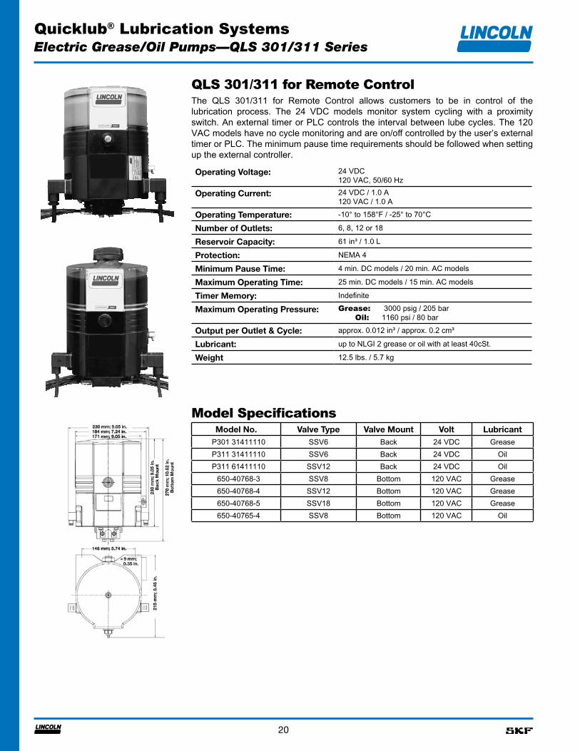
QLS 301/311 for Remote ControlThe QLS 301/311 for Remote Control allows customers to be in control of the lubrication process. The 24 VDC models monitor system cycling with a proximity switch. An external timer or PLC controls the interval between lube cycles. The 120 VAC models have no cycle monitoring and are on/off controlled by the user’s external timer or PLC. The minimum pause time requirements should be followed when setting up the external controller.
Operating Voltage: 24 VDC120 VAC, 50/60 Hz
Operating Current: 24 VDC / 1.0 A120 VAC / 1.0 A
Operating Temperature: -10° to 158°F / -25° to 70°C
Number of Outlets: 6, 8, 12 or 18
Reservoir Capacity: 61 in³ / 1.0 L
Protection: NEMA 4
Minimum Pause Time: 4 min. DC models / 20 min. AC models
Maximum Operating Time: 25 min. DC models / 15 min. AC models
Timer Memory: Indefinite
Maximum Operating Pressure: Grease: 3000 psig / 205 bar Oil: 1160 psi / 80 bar
Output per Outlet & Cycle: approx. 0.012 in³ / approx. 0.2 cm³
Lubricant: up to NLGI 2 grease or oil with at least 40cSt.
Weight 12.5 lbs. / 5.7 kg
Model SpecificationsModel No. Valve Type Valve Mount Volt Lubricant
P301 31411110 SSV6 Back 24 VDC GreaseP311 31411110 SSV6 Back 24 VDC OilP311 61411110 SSV12 Back 24 VDC Oil
650-40768-3 SSV8 Bottom 120 VAC Grease650-40768-4 SSV12 Bottom 120 VAC Grease650-40768-5 SSV18 Bottom 120 VAC Grease650-40765-4 SSV8 Bottom 120 VAC Oil
Electric Grease/Oil Pumps—QLS 301/311 Series
Quicklub® Lubrication Systems
21
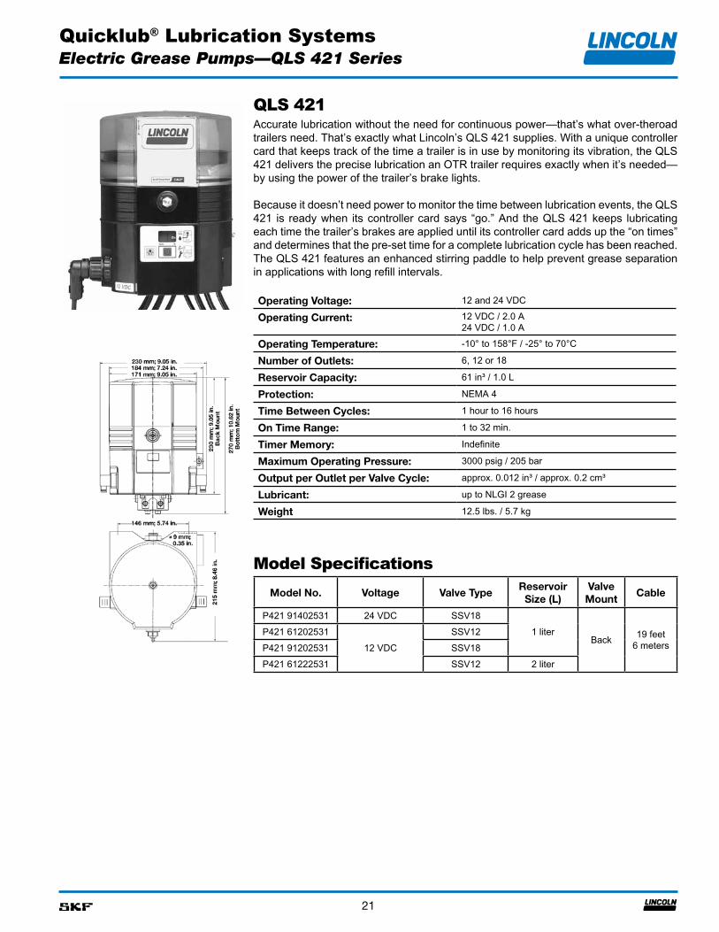
QLS 421Accurate lubrication without the need for continuous power—that’s what over-theroad trailers need. That’s exactly what Lincoln’s QLS 421 supplies. With a unique controller card that keeps track of the time a trailer is in use by monitoring its vibration, the QLS 421 delivers the precise lubrication an OTR trailer requires exactly when it’s needed—by using the power of the trailer’s brake lights.
Because it doesn’t need power to monitor the time between lubrication events, the QLS 421 is ready when its controller card says “go.” And the QLS 421 keeps lubricating each time the trailer’s brakes are applied until its controller card adds up the “on times” and determines that the pre-set time for a complete lubrication cycle has been reached. The QLS 421 features an enhanced stirring paddle to help prevent grease separation in applications with long refill intervals.
Operating Voltage: 12 and 24 VDC
Operating Current: 12 VDC / 2.0 A24 VDC / 1.0 A
Operating Temperature: -10° to 158°F / -25° to 70°C
Number of Outlets: 6, 12 or 18
Reservoir Capacity: 61 in³ / 1.0 L
Protection: NEMA 4
Time Between Cycles: 1 hour to 16 hours
On Time Range: 1 to 32 min.
Timer Memory: Indefinite
Maximum Operating Pressure: 3000 psig / 205 bar
Output per Outlet per Valve Cycle: approx. 0.012 in³ / approx. 0.2 cm³
Lubricant: up to NLGI 2 grease
Weight 12.5 lbs. / 5.7 kg
Model SpecificationsModel No. Voltage Valve Type
Reservoir Size (L)
Valve Mount
Cable
P421 91402531 24 VDC SSV181 liter
Back 19 feet 6 meters
P421 6120253112 VDC
SSV12P421 91202531 SSV18P421 61222531 SSV12 2 liter
Electric Grease Pumps—QLS 421 Series
Quicklub® Lubrication Systems
22
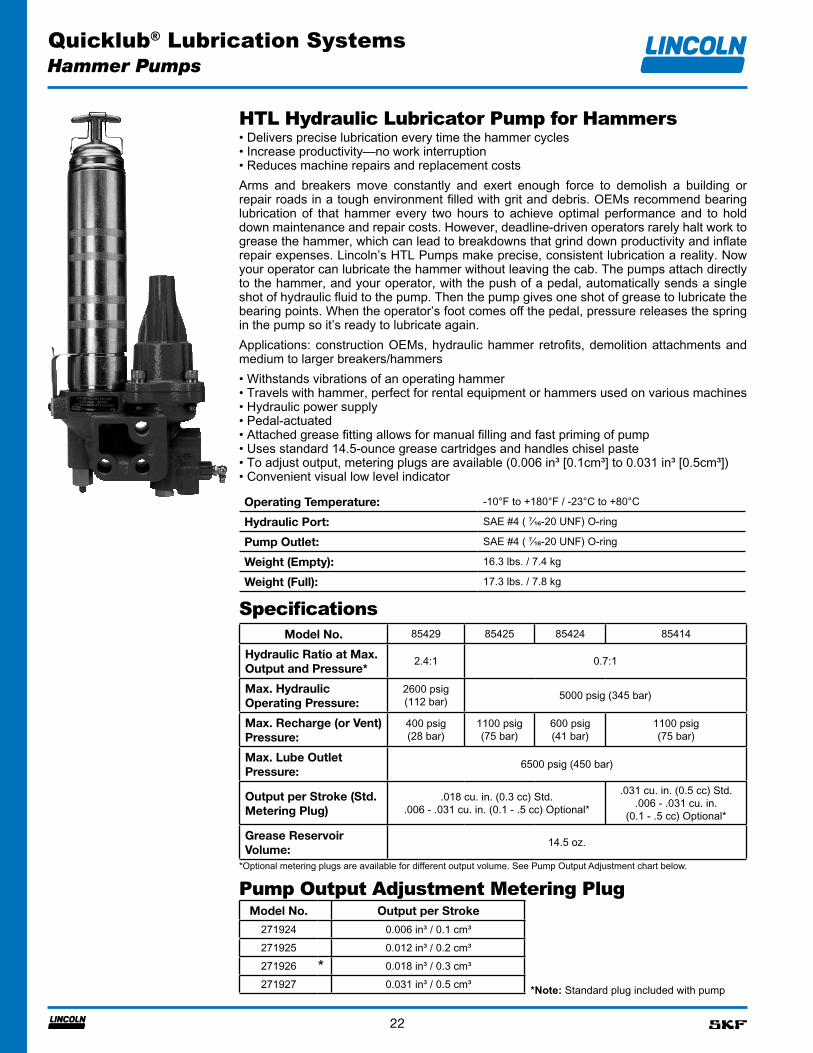
HTL Hydraulic Lubricator Pump for Hammers• Delivers precise lubrication every time the hammer cycles• Increase productivity—no work interruption• Reduces machine repairs and replacement costsArms and breakers move constantly and exert enough force to demolish a building or repair roads in a tough environment filled with grit and debris. OEMs recommend bearing lubrication of that hammer every two hours to achieve optimal performance and to hold down maintenance and repair costs. However, deadline-driven operators rarely halt work to grease the hammer, which can lead to breakdowns that grind down productivity and inflate repair expenses. Lincoln’s HTL Pumps make precise, consistent lubrication a reality. Now your operator can lubricate the hammer without leaving the cab. The pumps attach directly to the hammer, and your operator, with the push of a pedal, automatically sends a single shot of hydraulic fluid to the pump. Then the pump gives one shot of grease to lubricate the bearing points. When the operator’s foot comes off the pedal, pressure releases the spring in the pump so it’s ready to lubricate again.Applications: construction OEMs, hydraulic hammer retrofits, demolition attachments and medium to larger breakers/hammers• Withstands vibrations of an operating hammer• Travels with hammer, perfect for rental equipment or hammers used on various machines• Hydraulic power supply• Pedal-actuated• Attached grease fitting allows for manual filling and fast priming of pump• Uses standard 14.5-ounce grease cartridges and handles chisel paste• To adjust output, metering plugs are available (0.006 in³ [0.1cm³] to 0.031 in³ [0.5cm³])• Convenient visual low level indicator
Specifications
*Optional metering plugs are available for different output volume. See Pump Output Adjustment chart below.
Hammer Pumps
Pump Output Adjustment Metering PlugModel No. Output per Stroke
271924 0.006 in³ / 0.1 cm³271925 0.012 in³ / 0.2 cm³271926 * 0.018 in³ / 0.3 cm³271927 0.031 in³ / 0.5 cm³ *Note: Standard plug included with pump
Operating Temperature: -10°F to +180°F / -23°C to +80°C
Hydraulic Port: SAE #4 ( ⁷⁄₁₆-20 UNF) O-ring
Pump Outlet: SAE #4 ( ⁷⁄₁₆-20 UNF) O-ring
Weight (Empty): 16.3 lbs. / 7.4 kg
Weight (Full): 17.3 lbs. / 7.8 kg
Model No. 85429 85425 85424 85414
Hydraulic Ratio at Max. Output and Pressure*
2.4:1 0.7:1
Max. Hydraulic Operating Pressure:
2600 psig (112 bar) 5000 psig (345 bar)
Max. Recharge (or Vent) Pressure:
400 psig (28 bar)
1100 psig (75 bar)
600 psig (41 bar)
1100 psig (75 bar)
Max. Lube Outlet Pressure:
6500 psig (450 bar)
Output per Stroke (Std. Metering Plug)
.018 cu. in. (0.3 cc) Std..006 - .031 cu. in. (0.1 - .5 cc) Optional*
.031 cu. in. (0.5 cc) Std..006 - .031 cu. in.
(0.1 - .5 cc) Optional*
Grease Reservoir Volume:
14.5 oz.
Quicklub® Lubrication Systems
23
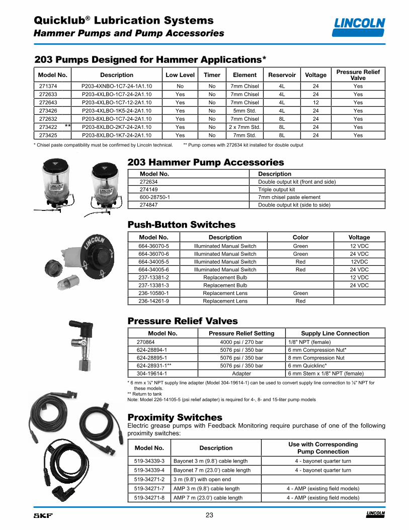
203 Pumps Designed for Hammer Applications*Model No. Description Low Level Timer Element Reservoir Voltage Pressure Relief
Valve271374 P203-4XNBO-1C7-24-1A1.10 No No 7mm Chisel 4L 24 Yes272633 P203-4XLBO-1C7-24-2A1.10 Yes No 7mm Chisel 4L 24 Yes272643 P203-4XLBO-1C7-12-2A1.10 Yes No 7mm Chisel 4L 12 Yes273426 P203-4XLBO-1K5-24-2A1.10 Yes No 5mm Std. 4L 24 Yes272632 P203-8XLBO-1C7-24-2A1.10 Yes No 7mm Chisel 8L 24 Yes273422 ** P203-8XLBO-2K7-24-2A1.10 Yes No 2 x 7mm Std. 8L 24 Yes273425 P203-8XLBO-1K7-24-2A1.10 Yes No 7mm Std. 8L 24 Yes
* Chisel paste compatibility must be confirmed by Lincoln technical. ** Pump comes with 272634 kit installed for double output
203 Hammer Pump Accessories
Hammer Pumps and Pump Accessories
Model No. Description272634 Double output kit (front and side)274149 Triple output kit600-28750-1 7mm chisel paste element274847 Double output kit (side to side)
Push-Button SwitchesModel No. Description Color Voltage664-36070-5 Illuminated Manual Switch Green 12 VDC664-36070-6 Illuminated Manual Switch Green 24 VDC664-34005-5 Illuminated Manual Switch Red 12VDC664-34005-6 Illuminated Manual Switch Red 24 VDC237-13381-2 Replacement Bulb 12 VDC237-13381-3 Replacement Bulb 24 VDC236-10580-1 Replacement Lens Green236-14261-9 Replacement Lens Red
Pressure Relief Valves
* 6 mm x ⅛" NPT supply line adapter (Model 304-19614-1) can be used to convert supply line connection to ⅛" NPT for these models.
** Return to tank Note: Model 226-14105-5 (psi relief adapter) is required for 4-, 8- and 15-liter pump models
Model No. Pressure Relief Setting Supply Line Connection270864 4000 psi / 270 bar 1/8" NPT (female)624-28894-1 5076 psi / 350 bar 6 mm Compression Nut*624-28895-1 5076 psi / 350 bar 8 mm Compression Nut624-28931-1** 5076 psi / 350 bar 6 mm Quicklinc*304-19614-1 Adapter 6 mm Stem x 1/8" NPT (female)
Proximity SwitchesElectric grease pumps with Feedback Monitoring require purchase of one of the following proximity switches:
Model No. DescriptionUse with Corresponding
Pump Connection
519-34339-3 Bayonet 3 m (9.8’) cable length 4 - bayonet quarter turn519-34339-4 Bayonet 7 m (23.0’) cable length 4 - bayonet quarter turn519-34271-2 3 m (9.8’) with open end519-34271-7 AMP 3 m (9.8’) cable length 4 - AMP (existing field models)519-34271-8 AMP 7 m (23.0’) cable length 4 - AMP (existing field models)
Quicklub® Lubrication Systems
24
Pump Accessories
Quicklub Pump Accessories
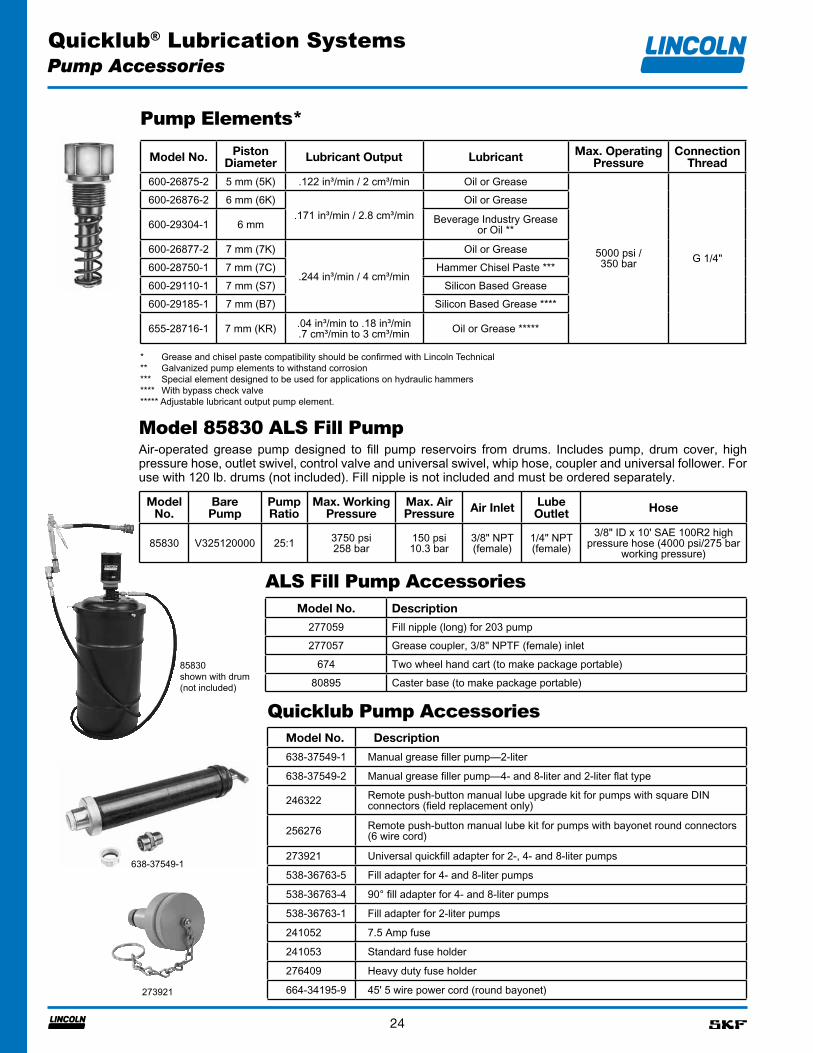
Pump Elements*
* Grease and chisel paste compatibility should be confirmed with Lincoln Technical** Galvanized pump elements to withstand corrosion*** Special element designed to be used for applications on hydraulic hammers**** With bypass check valve***** Adjustable lubricant output pump element.
Model No. Piston Diameter Lubricant Output Lubricant Max. Operating
PressureConnection
Thread
600-26875-2 5 mm (5K) .122 in³/min / 2 cm³/min Oil or Grease
5000 psi / 350 bar G 1/4"
600-26876-2 6 mm (6K).171 in³/min / 2.8 cm³/min
Oil or Grease
600-29304-1 6 mm Beverage Industry Grease or Oil **
600-26877-2 7 mm (7K)
.244 in³/min / 4 cm³/min
Oil or Grease600-28750-1 7 mm (7C) Hammer Chisel Paste ***600-29110-1 7 mm (S7) Silicon Based Grease600-29185-1 7 mm (B7) Silicon Based Grease ****
655-28716-1 7 mm (KR) .04 in³/min to .18 in³/min.7 cm³/min to 3 cm³/min Oil or Grease *****
638-37549-1
273921
Model No. Description
638-37549-1 Manual grease filler pump—2-liter
638-37549-2 Manual grease filler pump—4- and 8-liter and 2-liter flat type
246322 Remote push-button manual lube upgrade kit for pumps with square DIN connectors (field replacement only)
256276 Remote push-button manual lube kit for pumps with bayonet round connectors (6 wire cord)
273921 Universal quickfill adapter for 2-, 4- and 8-liter pumps
538-36763-5 Fill adapter for 4- and 8-liter pumps
538-36763-4 90° fill adapter for 4- and 8-liter pumps
538-36763-1 Fill adapter for 2-liter pumps
241052 7.5 Amp fuse
241053 Standard fuse holder
276409 Heavy duty fuse holder
664-34195-9 45' 5 wire power cord (round bayonet)
Model 85830 ALS Fill PumpAir-operated grease pump designed to fill pump reservoirs from drums. Includes pump, drum cover, high pressure hose, outlet swivel, control valve and universal swivel, whip hose, coupler and universal follower. For use with 120 lb. drums (not included). Fill nipple is not included and must be ordered separately.
Model No.
Bare Pump
Pump Ratio
Max. Working Pressure
Max. Air Pressure Air Inlet Lube
Outlet Hose
85830 V325120000 25:1 3750 psi258 bar
150 psi10.3 bar
3/8" NPT (female)
1/4" NPT (female)
3/8" ID x 10' SAE 100R2 high pressure hose (4000 psi/275 bar
working pressure)
ALS Fill Pump AccessoriesModel No. Description
277059 Fill nipple (long) for 203 pump277057 Grease coupler, 3/8" NPTF (female) inlet
674 Two wheel hand cart (to make package portable)80895 Caster base (to make package portable)
85830shown with drum (not included)
Quicklub® Lubrication Systems
25
Installation Components
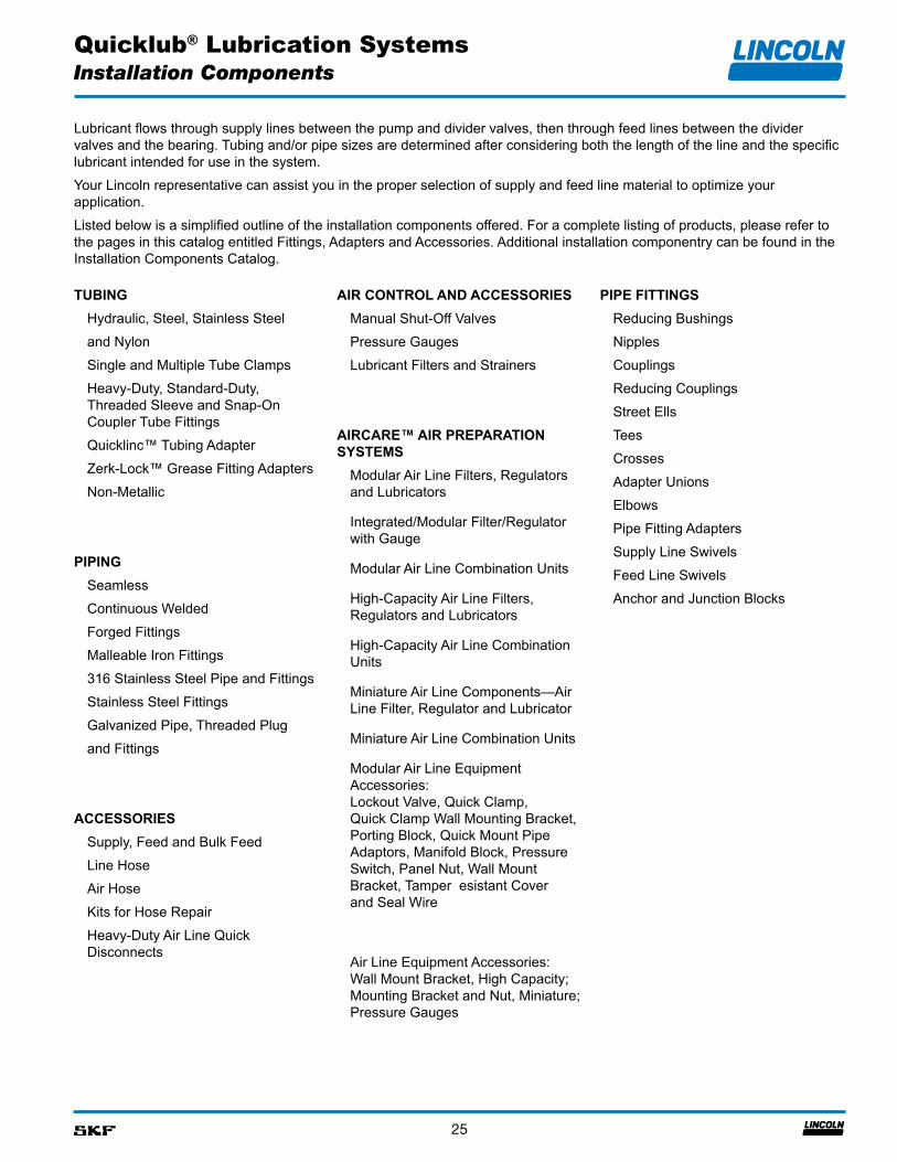
Lubricant flows through supply lines between the pump and divider valves, then through feed lines between the divider valves and the bearing. Tubing and/or pipe sizes are determined after considering both the length of the line and the specific lubricant intended for use in the system.
Your Lincoln representative can assist you in the proper selection of supply and feed line material to optimize your application.
Listed below is a simplified outline of the installation components offered. For a complete listing of products, please refer to the pages in this catalog entitled Fittings, Adapters and Accessories. Additional installation componentry can be found in the Installation Components Catalog.
TUBINGHydraulic, Steel, Stainless Steel
and Nylon
Single and Multiple Tube Clamps
Heavy-Duty, Standard-Duty, Threaded Sleeve and Snap-On Coupler Tube Fittings
Quicklinc™ Tubing Adapter
Zerk-Lock™ Grease Fitting Adapters
Non-Metallic
PIPINGSeamless
Continuous Welded
Forged Fittings
Malleable Iron Fittings
316 Stainless Steel Pipe and Fittings
Stainless Steel Fittings
Galvanized Pipe, Threaded Plug
and Fittings
ACCESSORIESSupply, Feed and Bulk Feed
Line Hose
Air Hose
Kits for Hose Repair
Heavy-Duty Air Line Quick Disconnects
AIR CONTROL AND ACCESSORIESManual Shut-Off Valves
Pressure Gauges
Lubricant Filters and Strainers
AIRCARE™ AIR PREPARATION SYSTEMS
Modular Air Line Filters, Regulators and Lubricators
Integrated/Modular Filter/Regulator with Gauge
Modular Air Line Combination Units
High-Capacity Air Line Filters, Regulators and Lubricators
High-Capacity Air Line Combination Units
Miniature Air Line Components—Air Line Filter, Regulator and Lubricator
Miniature Air Line Combination Units
Modular Air Line Equipment Accessories: Lockout Valve, Quick Clamp, Quick Clamp Wall Mounting Bracket, Porting Block, Quick Mount Pipe Adaptors, Manifold Block, Pressure Switch, Panel Nut, Wall Mount Bracket, Tamper esistant Cover and Seal Wire
Air Line Equipment Accessories: Wall Mount Bracket, High Capacity; Mounting Bracket and Nut, Miniature; Pressure Gauges
PIPE FITTINGSReducing Bushings
Nipples
Couplings
Reducing Couplings
Street Ells
Tees
Crosses
Adapter Unions
Elbows
Pipe Fitting Adapters
Supply Line Swivels
Feed Line Swivels
Anchor and Junction Blocks
Quicklub® Lubrication Systems
26
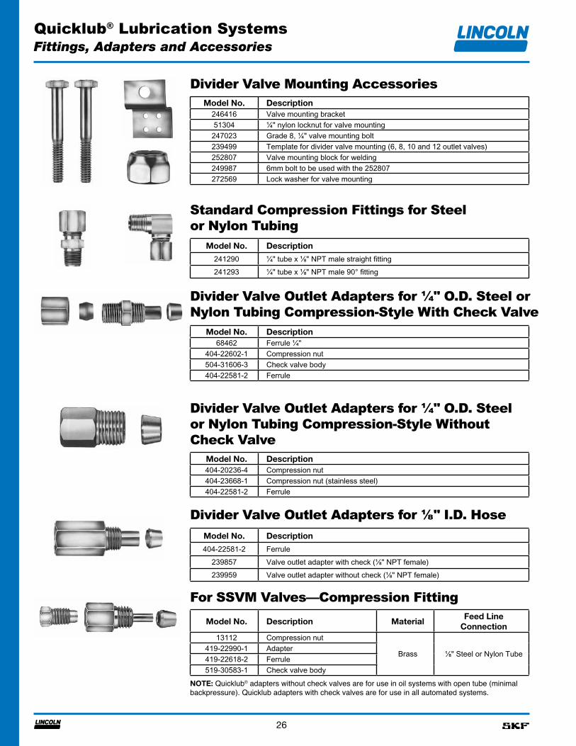
Divider Valve Mounting AccessoriesModel No. Description
246416 Valve mounting bracket51304 ¼" nylon locknut for valve mounting247023 Grade 8, ¼" valve mounting bolt239499 Template for divider valve mounting (6, 8, 10 and 12 outlet valves)252807 Valve mounting block for welding249987 6mm bolt to be used with the 252807272569 Lock washer for valve mounting
Standard Compression Fittings for Steel or Nylon Tubing
Model No. Description
241290 ¹⁄₄" tube x ¹⁄₈" NPT male straight fitting241293 ¹⁄₄" tube x ¹⁄₈" NPT male 90° fitting
Divider Valve Outlet Adapters for ¼" O.D. Steel or Nylon Tubing Compression-Style With Check Valve
Model No. Description68462 Ferrule ¹⁄₄"
404-22602-1 Compression nut504-31606-3 Check valve body404-22581-2 Ferrule
Divider Valve Outlet Adapters for ¼" O.D. Steel or Nylon Tubing Compression-Style Without Check Valve
Model No. Description404-20236-4 Compression nut404-23668-1 Compression nut (stainless steel)404-22581-2 Ferrule
Divider Valve Outlet Adapters for ⅛" I.D. HoseModel No. Description
404-22581-2 Ferrule239857 Valve outlet adapter with check (⅛" NPT female)239959 Valve outlet adapter without check (⅛" NPT female)
For SSVM Valves—Compression FittingModel No. Description Material
Feed Line Connection
13112 Compression nut
Brass ⅛" Steel or Nylon Tube419-22990-1 Adapter419-22618-2 Ferrule519-30583-1 Check valve body
NOTE: Quicklub® adapters without check valves are for use in oil systems with open tube (minimal backpressure). Quicklub adapters with check valves are for use in all automated systems.
Fittings, Adapters and Accessories
Quicklub® Lubrication Systems
27
Fittings, Adapters and Accessories
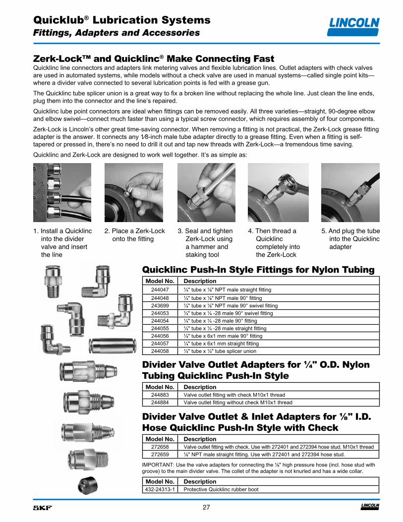
Zerk-Lock™ and Quicklinc® Make Connecting FastQuicklinc line connectors and adapters link metering valves and flexible lubrication lines. Outlet adapters with check valves are used in automated systems, while models without a check valve are used in manual systems—called single point kits—where a divider valve connected to several lubrication points is fed with a grease gun.The Quicklinc tube splicer union is a great way to fix a broken line without replacing the whole line. Just clean the line ends, plug them into the connector and the line’s repaired.Quicklinc lube point connectors are ideal when fittings can be removed easily. All three varieties—straight, 90-degree elbow and elbow swivel—connect much faster than using a typical screw connector, which requires assembly of four components.Zerk-Lock is Lincoln’s other great time-saving connector. When removing a fitting is not practical, the Zerk-Lock grease fitting adapter is the answer. It connects any 1⁄8-inch male tube adapter directly to a grease fitting. Even when a fitting is self-tapered or pressed in, there’s no need to drill it out and tap new threads with Zerk-Lock—a tremendous time saving.Quicklinc and Zerk-Lock are designed to work well together. It’s as simple as:
Quicklinc Push-In Style Fittings for Nylon Tubing
Divider Valve Outlet Adapters for ¼" O.D. Nylon Tubing Quicklinc Push-In Style
Model No. Description244883 Valve outlet fitting with check M10x1 thread244884 Valve outlet fitting without check M10x1 thread
Divider Valve Outlet & Inlet Adapters for ⅛" I.D. Hose Quicklinc Push-In Style with Check
Model No. Description272658 Valve outlet fitting with check. Use with 272401 and 272394 hose stud. M10x1 thread272659 ⅛" NPT male straight fitting. Use with 272401 and 272394 hose stud.
Model No. Description244047 ¹⁄₄" tube x ¹⁄₈" NPT male straight fitting244048 ¹⁄₄" tube x ¹⁄₈" NPT male 90° fitting243699 ¹⁄₄" tube x ¹⁄₈" NPT male 90° swivel fitting244053 ¹⁄₄" tube x ¹⁄₄ -28 male 90° swivel fitting244054 ¹⁄₄" tube x ¹⁄₄ -28 male 90° fitting244055 ¹⁄₄" tube x ¹⁄₄ -28 male straight fitting244056 ¹⁄₄" tube x 6x1 mm male 90° fitting244057 ¹⁄₄" tube x 6x1 mm straight fitting244058 ¹⁄₄" tube x ¹⁄₄" tube splicer union
IMPORTANT: Use the valve adapters for connecting the ⅛" high pressure hose (incl. hose stud with groove) to the main divider valve. The collet of the adapter is not knurled and has a wide collar.
Model No. Description432-24313-1 Protective Quicklinc rubber boot
1. Install a Quicklinc into the divider valve and insert the line
2. Place a Zerk-Lock onto the fitting
3. Seal and tighten Zerk-Lock using a hammer and staking tool
4. Then thread a Quicklinc completely into the Zerk-Lock
5. And plug the tube into the Quicklinc adapter
Quicklub® Lubrication Systems
28
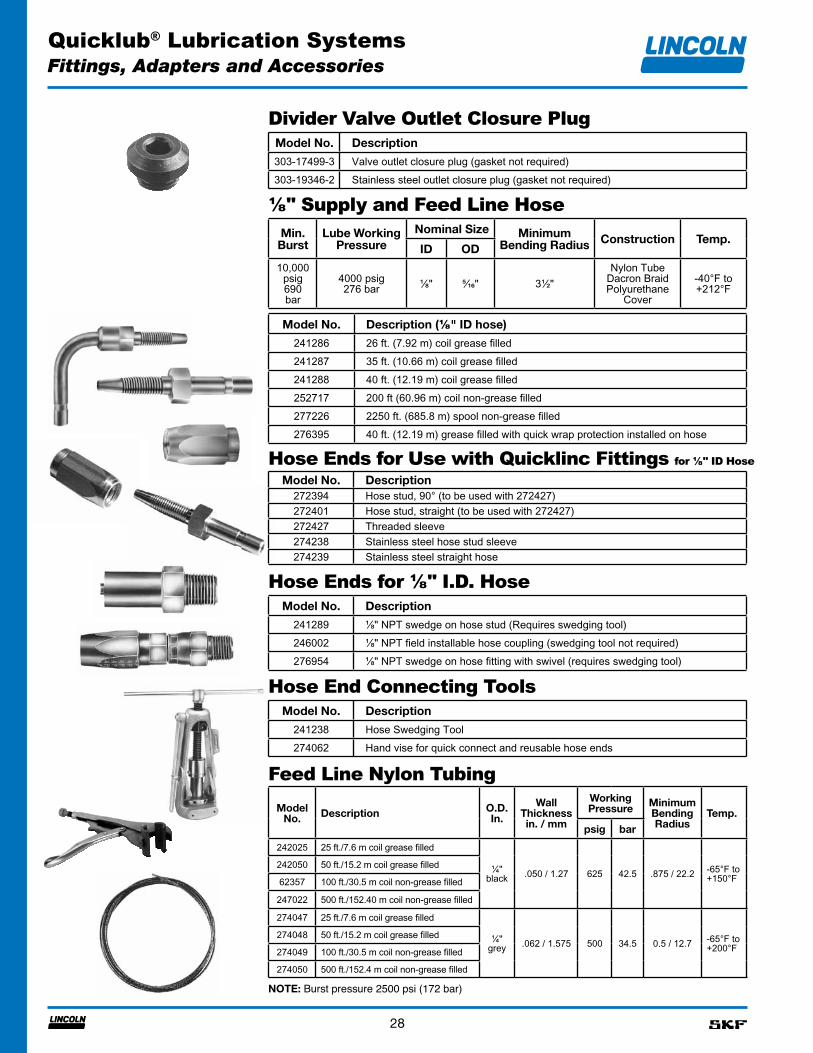
Divider Valve Outlet Closure PlugModel No. Description
303-17499-3 Valve outlet closure plug (gasket not required)303-19346-2 Stainless steel outlet closure plug (gasket not required)
⅛" Supply and Feed Line HoseMin. Burst
Lube Working Pressure
Nominal Size Minimum Bending Radius Construction Temp.
ID OD
10,000 psig 690 bar
4000 psig 276 bar ⅛" ⁵⁄₁₆" 3½"
Nylon Tube Dacron Braid Polyurethane
Cover
-40°F to +212°F
Hose Ends for Use with Quicklinc Fittings for ⅛" ID Hose
Model No. Description272394 Hose stud, 90° (to be used with 272427)272401 Hose stud, straight (to be used with 272427)272427 Threaded sleeve274238 Stainless steel hose stud sleeve274239 Stainless steel straight hose
Hose Ends for ⅛" I.D. HoseModel No. Description
241289 ¹⁄₈" NPT swedge on hose stud (Requires swedging tool)246002 ¹⁄₈" NPT field installable hose coupling (swedging tool not required)276954 ¹⁄₈" NPT swedge on hose fitting with swivel (requires swedging tool)
Hose End Connecting ToolsModel No. Description
241238 Hose Swedging Tool274062 Hand vise for quick connect and reusable hose ends
Feed Line Nylon Tubing
Fittings, Adapters and Accessories
Model No. Description O.D.
In.
Wall Thickness in. / mm
Working Pressure Minimum
Bending Radius
Temp.
psig bar
242025 25 ft./7.6 m coil grease filled
¼" black .050 / 1.27 625 42.5 .875 / 22.2 -65°F to
+150°F242050 50 ft./15.2 m coil grease filled
62357 100 ft./30.5 m coil non-grease filled
247022 500 ft./152.40 m coil non-grease filled
274047 25 ft./7.6 m coil grease filled
¼" grey .062 / 1.575 500 34.5 0.5 / 12.7 -65°F to
+200°F274048 50 ft./15.2 m coil grease filled
274049 100 ft./30.5 m coil non-grease filled
274050 500 ft./152.4 m coil non-grease filled
Model No. Description (⅛" ID hose)
241286 26 ft. (7.92 m) coil grease filled241287 35 ft. (10.66 m) coil grease filled241288 40 ft. (12.19 m) coil grease filled252717 200 ft (60.96 m) coil non-grease filled277226 2250 ft. (685.8 m) spool non-grease filled276395 40 ft. (12.19 m) grease filled with quick wrap protection installed on hose
NOTE: Burst pressure 2500 psi (172 bar)
Quicklub® Lubrication Systems
29
No. 51055
Steel TubingModel No.
Size (O.D. x Wall)Working Pressure Type
O.D. Wall Length62175 ¹⁄₈ .020" 25 ft/7.6 m 4400 psig / 300 bar Coil
Nylon Tubing
Model No.Size (O.D. x Wall)
Working PressureMinimum Bending RadiusO.D. Wall Length
62256⅛" .026"
25 ft/7.6 m625 psig / 42.5 bar .375"62278 100 ft/30.5 m
62956 500 ft/152 m
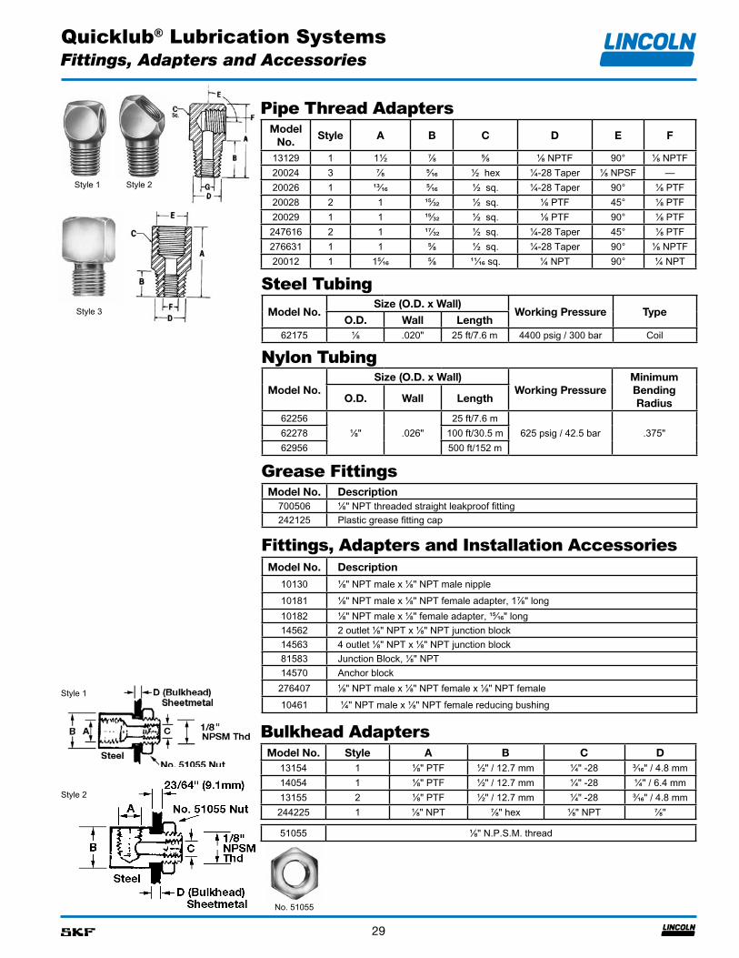
Pipe Thread Adapters
Bulkhead AdaptersModel No. Style A B C D
13154 1 ¹⁄₈" PTF ¹⁄₂" / 12.7 mm ¹⁄₄" -28 ³⁄₁₆" / 4.8 mm14054 1 ¹⁄₈" PTF ¹⁄₂" / 12.7 mm ¹⁄₄" -28 ¼" / 6.4 mm13155 2 ¹⁄₈" PTF ¹⁄₂" / 12.7 mm ¹⁄₄" -28 ³⁄₁₆" / 4.8 mm244225 1 ¹⁄₈" NPT ⁷⁄₈" hex ¹⁄₈" NPT ⁷⁄₈"
Model No. Description
10130 ⅛" NPT male x ⅛" NPT male nipple10181 ⅛" NPT male x ⅛" NPT female adapter, 1⅞" long10182 ⅛" NPT male x ⅛" female adapter, ¹⁵⁄₁₆" long14562 2 outlet ⅛" NPT x ⅛" NPT junction block14563 4 outlet ⅛" NPT x ⅛" NPT junction block81583 Junction Block, ⅛" NPT14570 Anchor block276407 ¹⁄₈" NPT male x ¹⁄₈" NPT female x ¹⁄₈" NPT female10461 ¼" NPT male x ¹⁄₈" NPT female reducing bushing
Grease Fittings
Model No.
Style A B C D E F
13129 1 1½ ⁷⁄₈ ⁵⁄₈ ⅛ NPTF 90° ¹⁄₈ NPTF20024 3 ⁷⁄₈ ⁵⁄₁₆ ½ hex ¼-28 Taper ¹⁄₈ NPSF —20026 1 ¹³⁄₁₆ ⁵⁄₁₆ ½ sq. ¼-28 Taper 90° ¹⁄₈ PTF20028 2 1 ¹⁵⁄₃₂ ½ sq. ⅛ PTF 45° ¹⁄₈ PTF20029 1 1 ¹⁵⁄₃₂ ½ sq. ⅛ PTF 90° ¹⁄₈ PTF247616 2 1 ¹⁷⁄₃₂ ½ sq. ¼-28 Taper 45° ¹⁄₈ PTF276631 1 1 ⁵⁄₈ ½ sq. ¼-28 Taper 90° ¹⁄₈ NPTF20012 1 1⁵⁄₁₆ ⁵⁄₈ ¹¹⁄₁₆ sq. ¼ NPT 90° ¼ NPT
Fittings, Adapters and Installation Accessories
Model No. Description700506 ⅛" NPT threaded straight leakproof fitting242125 Plastic grease fitting cap
Style 2Style 1
Fittings, Adapters and Accessories
51055 ¹⁄₈" N.P.S.M. thread
Style 3
Style 1
Style 2
Quicklub® Lubrication Systems
30
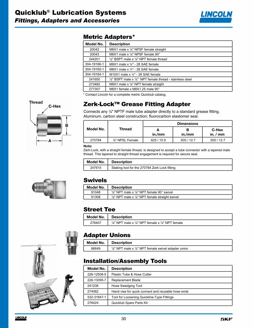
Zerk-Lock™ Grease Fitting Adapter
Fittings, Adapters and Accessories
Connects any ⅛" NPTF male tube adapter directly to a standard grease fitting.Aluminum, carbon steel construction; fluorocarbon elastomer seal.
Model No. ThreadDimensions
A in./mm
B in./mm
C-Hex in. / mm
270784 ¹⁄₈" NPSL Female .625 / 15.9 .500 / 12.7 .500 / 12.7
Note:Zerk-Lock, with a straight female thread, is designed to accept a tube connector with a tapered male thread. This tapered to straight thread engagement is required for secure seal.
SwivelsModel No. Description
91048 ⅛" NPT male x ⅛" NPT female 90° swivel91308 ⅛" NPT male x ⅛" NPT female straight swivel
Street TeeModel No. Description
276407 ¹⁄₈" NPT male x ¹⁄₈" NPT female x ¹⁄₈" NPT female
Adapter UnionsModel No. Description
66649 ⅛" NPT male x ⅛" NPT female swivel adapter union
Installation/Assembly ToolsModel No. Description
226-12508-5 Plastic Tube & Hose Cutter226-13095-7 Replacement Blade241238 Hose Swedging Tool274062 Hand vise for quick connect and reusable hose ends532-31847-1 Tool for Loosening Quickline-Type Fittings276424 Quicklub Spare Parts Kit
Model No. Description
247615 Staking tool for the 270784 Zerk Lock fitting
Metric Adapters*Model No. Description
20042 M6X1 male x ⅛" NPSF female straight20043 M6X1 male x ⅛" NPSF female 90°244201 ⅛" BSPT male x ⅛" NPT female thread
304-19166-1 M6X1 male x ¼" - 28 SAE female304-19165-1 M8X1 male x ¼" - 28 SAE female304-19164-1 M10X1 male x ¼" - 28 SAE female
241650 ⅛" BSPT male x ⅛" NPT female thread - stainless steel273482 M8X1 male x ⅛" NPT female straight277307 M8X1 female x M8X1.25 male 90°
* Contact Lincoln for a complete metric Quicklub catalog.
Quicklub® Lubrication Systems
31
System Finishing AccessoriesModel
No.Description
241110 Feed line bundling spiral wrap (10 ft. / 3 m length)241120 Feed line bundling spiral wrap (20 feet/6m of spiral wrap)276693 300 feet of spiral wrap241055 Nylon ties (50 count poly bag) 7" / 177.8 m length241054 Nylon ties (100 count poly bag) 7" / 177.8 m length274097 20 feet/6m of ³⁄₈" convoluted loom/split wrap274098 20 feet/6m of ¹⁄₂" convoluted loom/split wrap274099 20 feet/6m of ⁵₈" convoluted loom/split wrap
Pump Mounting Bracket and Hardware for 203 Series and QLS 300 & 400 Series Pumps
Model No.
Description
249520 Pump mounting bracket for 203/301/401/653 Series pumps249209 12 mm x 1½" long grade 8 bolt for 249520 pump bracket (2 required)274820 Pump and primary valve mounting bracket
Stand Offs for Mounting SSV Valves, P-Clamps and Angle Iron
Model No.
Description
252807 Valve mounting block for welding249987 6mm bolt to be used with the 252807249850 12mm round stand off270928 12mm square stand off249848 12mm x ⁵⁄₈" long bolt to be used with 249850 and 270928249851 10mm round stand off249849 10mm x ⁵⁄₈" long bolt to be used with 249851
Fittings, Adapters and Accessories
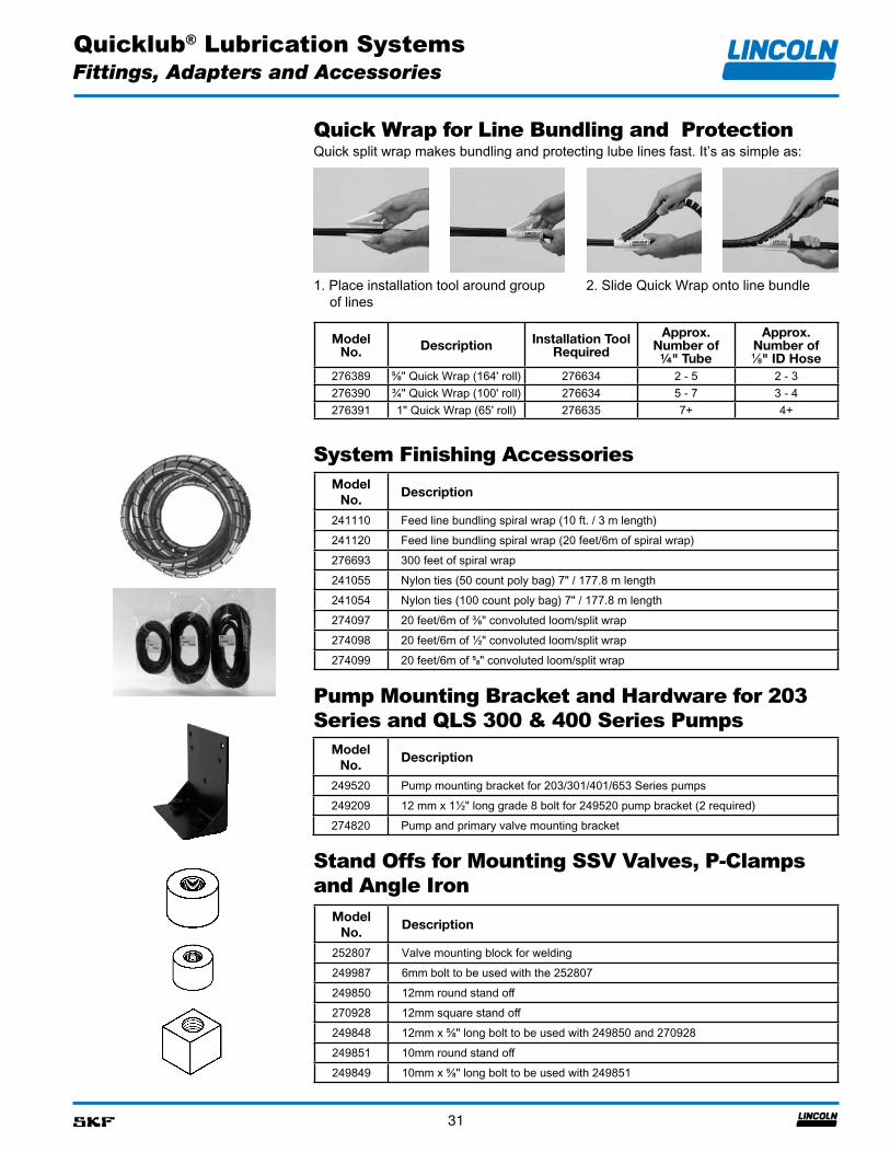
Quick Wrap for Line Bundling and ProtectionQuick split wrap makes bundling and protecting lube lines fast. It’s as simple as:
1. Place installation tool around group of lines
2. Slide Quick Wrap onto line bundle
Model No. Description Installation Tool
Required
Approx. Number of ¼" Tube
Approx. Number of ⅛" ID Hose
276389 ⅝" Quick Wrap (164' roll) 276634 2 - 5 2 - 3276390 ¾" Quick Wrap (100' roll) 276634 5 - 7 3 - 4276391 1" Quick Wrap (65' roll) 276635 7+ 4+
Quicklub® Lubrication Systems
32
Kits
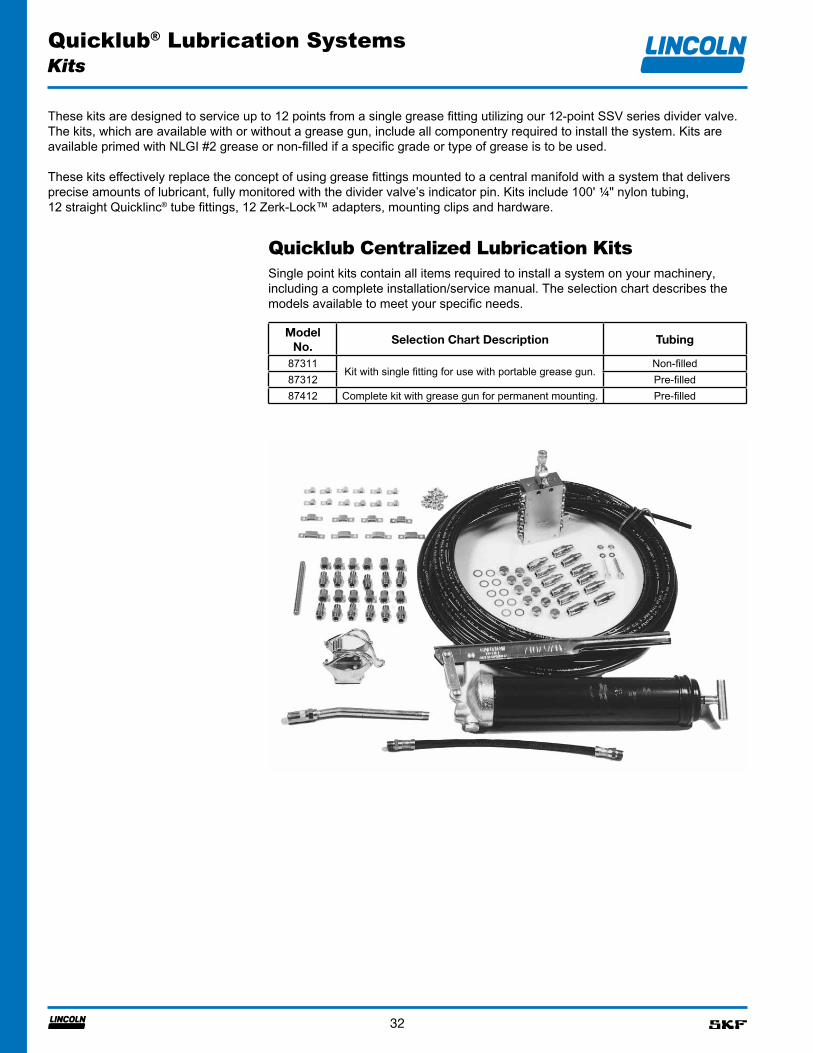
Quicklub Centralized Lubrication Kits
Model No.
Selection Chart Description Tubing
87311Kit with single fitting for use with portable grease gun.
Non-filled87312 Pre-filled87412 Complete kit with grease gun for permanent mounting. Pre-filled
Single point kits contain all items required to install a system on your machinery, including a complete installation/service manual. The selection chart describes the models available to meet your specific needs.
These kits are designed to service up to 12 points from a single grease fitting utilizing our 12-point SSV series divider valve. The kits, which are available with or without a grease gun, include all componentry required to install the system. Kits are available primed with NLGI #2 grease or non-filled if a specific grade or type of grease is to be used.
These kits effectively replace the concept of using grease fittings mounted to a central manifold with a system that delivers precise amounts of lubricant, fully monitored with the divider valve’s indicator pin. Kits include 100' ¼" nylon tubing, 12 straight Quicklinc® tube fittings, 12 Zerk-Lock™ adapters, mounting clips and hardware.
Quicklub® Lubrication Systems
33
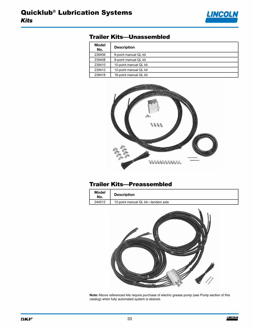
Trailer Kits—Unassembled
Kits
Model No.
Description
239406 6-point manual QL kit239408 8-point manual QL kit239410 10-point manual QL kit239412 12-point manual QL kit239418 18-point manual QL kit
Trailer Kits—PreassembledModel
No.Description
244512 12-point manual QL kit—tandem axle
Note: Above referenced kits require purchase of electric grease pump (see Pump section of this catalog) when fully automated system is desired.
Quicklub® Lubrication Systems
34
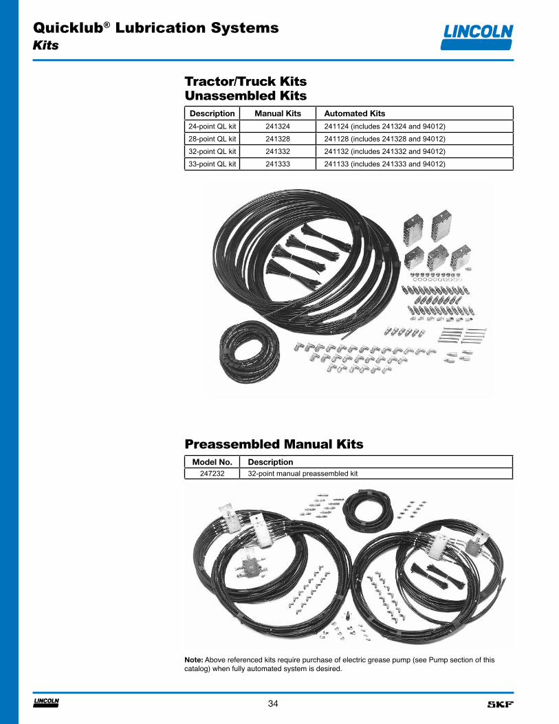
Tractor/Truck Kits
Kits
Unassembled KitsDescription Manual Kits Automated Kits
24-point QL kit 241324 241124 (includes 241324 and 94012)28-point QL kit 241328 241128 (includes 241328 and 94012)32-point QL kit 241332 241132 (includes 241332 and 94012)33-point QL kit 241333 241133 (includes 241333 and 94012)
Preassembled Manual KitsModel No. Description
247232 32-point manual preassembled kit
Note: Above referenced kits require purchase of electric grease pump (see Pump section of this catalog) when fully automated system is desired.
Quicklub® Lubrication Systems
35
Numerical Index
674. . . . . . . . . . . . . . . . . . . 2410130. . . . . . . . . . . . . . . . . 2910181. . . . . . . . . . . . . . . . . 2910182. . . . . . . . . . . . . . . . . 2910461. . . . . . . . . . . . . . . . . 2913112 . . . . . . . . . . . . . . . . . 2613129. . . . . . . . . . . . . . . . . 2913154. . . . . . . . . . . . . . . . . 2913155. . . . . . . . . . . . . . . . . 2914054. . . . . . . . . . . . . . . . . 2914562. . . . . . . . . . . . . . . . . 2914563. . . . . . . . . . . . . . . . . 2914570. . . . . . . . . . . . . . . . . 2920012. . . . . . . . . . . . . . . . . 2920024. . . . . . . . . . . . . . . . . 2920026. . . . . . . . . . . . . . . . . 2920028. . . . . . . . . . . . . . . . . 2920029. . . . . . . . . . . . . . . . . 2920042. . . . . . . . . . . . . . . . . 3020043. . . . . . . . . . . . . . . . . 30226-12508-5 . . . . . . . . . . . 30226-13095-7 . . . . . . . . . . . 30226-14105-5 . . . . . . . . . . . 23236-10580-1 . . . . . . . . . . . 23236-14261-9 . . . . . . . . . . . 23237-13381-2 . . . . . . . . . . . 23237-13381-3 . . . . . . . . . . . 23239406. . . . . . . . . . . . . . . . 33239408. . . . . . . . . . . . . . . . 33239410. . . . . . . . . . . . . . . . 33239412. . . . . . . . . . . . . . . . 33239418. . . . . . . . . . . . . . . . 33239499. . . . . . . . . . . . . . . . 26239857. . . . . . . . . . . . . . . . 26239959. . . . . . . . . . . . . . . . 26241052. . . . . . . . . . . . . . . . 24241053. . . . . . . . . . . . . . . . 24241054. . . . . . . . . . . . . . . . 31241055. . . . . . . . . . . . . . . . 31241110 . . . . . . . . . . . . . . . . 31241116 . . . . . . . . . . . . . . . . 34241120 . . . . . . . . . . . . . . . . 31241124 . . . . . . . . . . . . . . . . 34241128 . . . . . . . . . . . . . . . . 34241129 . . . . . . . . . . . . . . . . 34241132 . . . . . . . . . . . . . . . . 34241133 . . . . . . . . . . . . . . . . 34241238. . . . . . . . . . . . . 28, 30241286. . . . . . . . . . . . . . . . 28241287. . . . . . . . . . . . . . . . 28 241288. . . . . . . . . . . . . . . . 28241289. . . . . . . . . . . . . . . . 28241290. . . . . . . . . . . . . . . . 26241293. . . . . . . . . . . . . . . . 26
241324. . . . . . . . . . . . . . . . 34241328. . . . . . . . . . . . . . . . 34241332. . . . . . . . . . . . . . . . 34241333. . . . . . . . . . . . . . . . 34241650. . . . . . . . . . . . . . 4, 30242025. . . . . . . . . . . . . . . . 28242050. . . . . . . . . . . . . . . . 28242125. . . . . . . . . . . . . . . . 29243699. . . . . . . . . . . . . . . . 27244047. . . . . . . . . . . . . . . . 27244048. . . . . . . . . . . . . . . . 27244053. . . . . . . . . . . . . . . . 27244054. . . . . . . . . . . . . . . . 27244055. . . . . . . . . . . . . . . . 27244056. . . . . . . . . . . . . . . . 27244057. . . . . . . . . . . . . . . . 27244058. . . . . . . . . . . . . . . . 27244201. . . . . . . . . . . . . . . . 30244225. . . . . . . . . . . . . . . . 29244512. . . . . . . . . . . . . . . . 33244883. . . . . . . . . . . . . . . . 27244884. . . . . . . . . . . . . . . . 27246002. . . . . . . . . . . . . . . . 28246322. . . . . . . . . . . . . . . . 24246416. . . . . . . . . . . . . . . . 26247022. . . . . . . . . . . . . . . . 28247023. . . . . . . . . . . . . . . . 26247232. . . . . . . . . . . . . . . . 34247615. . . . . . . . . . . . . . . . 30247616. . . . . . . . . . . . . . . . 29249010. . . . . . . . . . . . . . . . . 4249209. . . . . . . . . . . . . . . . 31249520. . . . . . . . . . . . . . . . 31249848. . . . . . . . . . . . . . . . 31249849. . . . . . . . . . . . . . . . 31249850. . . . . . . . . . . . . . . . 31249851. . . . . . . . . . . . . . . . 31249987. . . . . . . . . . . . . 26, 31252717. . . . . . . . . . . . . . . . 28252807. . . . . . . . . . . . . 26, 31256276. . . . . . . . . . . . . . . . 24270784. . . . . . . . . . . . . . . . 30270864. . . . . . . . . . . . . . 8, 23270928. . . . . . . . . . . . . . . . 31271374. . . . . . . . . . . . . . . . 23271924. . . . . . . . . . . . . . . . 22271925. . . . . . . . . . . . . . . . 22271926. . . . . . . . . . . . . . . . 22271927. . . . . . . . . . . . . . . . 22272394. . . . . . . . . . . . . 27, 28272401. . . . . . . . . . . . . 27, 28272427. . . . . . . . . . . . . . . . 28272569. . . . . . . . . . . . . . . . 26272632. . . . . . . . . . . . . . . . 23
272633. . . . . . . . . . . . . . . . 23272634. . . . . . . . . . . . . . . . 23272643. . . . . . . . . . . . . . . . 23272658. . . . . . . . . . . . . . . . 27272659. . . . . . . . . . . . . . . . 27273422. . . . . . . . . . . . . . . . 23273425. . . . . . . . . . . . . . . . 23273426. . . . . . . . . . . . . . . . 23273482. . . . . . . . . . . . . . . . 30273921. . . . . . . . . . . . . . . . 24274047. . . . . . . . . . . . . . . . 28274048. . . . . . . . . . . . . . . . 28274049. . . . . . . . . . . . . . . . 28274050. . . . . . . . . . . . . . . . 28274062. . . . . . . . . . . . . 28, 30274097. . . . . . . . . . . . . . . . 31274098. . . . . . . . . . . . . . . . 31274099. . . . . . . . . . . . . . . . 31274149. . . . . . . . . . . . . . . . 23274238. . . . . . . . . . . . . . . . 28274239. . . . . . . . . . . . . . . . 28274820. . . . . . . . . . . . . . . . 31274847. . . . . . . . . . . . . . . . 23276389. . . . . . . . . . . . . . . . 31276390. . . . . . . . . . . . . . . . 31276391. . . . . . . . . . . . . . . . 31276395. . . . . . . . . . . . . . . . 28276407. . . . . . . . . . . . . 29, 30276409. . . . . . . . . . . . . . . . 24276424. . . . . . . . . . . . . . . . 30276631. . . . . . . . . . . . . . . . 29276634. . . . . . . . . . . . . . . . 31276635. . . . . . . . . . . . . . . . 31276693. . . . . . . . . . . . . . . . 31276954. . . . . . . . . . . . . . . . 28277057. . . . . . . . . . . . . . . . 24277059. . . . . . . . . . . . . . . . 24277226. . . . . . . . . . . . . . . . 28277307. . . . . . . . . . . . . . . . 30303-16118-1 . . . . . . . . . . . . 6303-16119-1 . . . . . . . . . . . . 6303-16120-1 . . . . . . . . . . . . 6303-16121-1 . . . . . . . . . . . . 6303-16122-1 . . . . . . . . . . . . 6303-16123-1 . . . . . . . . . . . . 6303-16124-1 . . . . . . . . . . . . 6303-16125-1 . . . . . . . . . . . . 6303-16126-1 . . . . . . . . . . . . 6303-16127-1 . . . . . . . . . . . . 6303-17499-3 . . . . . . . . . . . 28303-19346-2 . . . . . . . . . . . 28304-19164-1 . . . . . . . . . . . 30304-19165-1 . . . . . . . . . . . 30304-19166-1 . . . . . . . . . . . 30
304-19614-1 . . . . . . . . . 9, 23404-20236-4 . . . . . . . . . . . 26404-22581-2 . . . . . . . . . . . 26404-22602-1 . . . . . . . . . . . 26404-23668-1 . . . . . . . . . . . 26419-22618-2 . . . . . . . . . . . 26419-22990-1 . . . . . . . . . . . 26432-24313-1 . . . . . . . . . . . 27444-70490-1 . . . . . . . . . . . 14444-70491-1 . . . . . . . . . . . 14504-31606-3 . . . . . . . . . . . 2651055. . . . . . . . . . . . . . . . . 2951304. . . . . . . . . . . . . . . . . 26519-30583-1 . . . . . . . . . . . 26519-34271-2 . . . . . . . . . . . 23519-34271-7 . . . . . . . . . . . 23519-34271-8 . . . . . . . . . . . 23519-34339-3 . . . . . . . . . . . 23519-34339-4 . . . . . . . . . . . 23532-31847-1 . . . . . . . . . . . 30538-36763-1 . . . . . . . . . . . 24538-36763-4 . . . . . . . . . . . 24538-36763-5 . . . . . . . . . . . 24544-32022-1 . . . . . . . . . . . 14544-32023-1 . . . . . . . . . . . 14544-32695-1 . . . . . . . . . . . 14544-32696-1 . . . . . . . . . . . 14544-32957-2 . . . . . . . . . . . 14549-34254-1 . . . . . . . . . . . . 6549-34254-2 . . . . . . . . . . . . 6549-34254-3 . . . . . . . . . . . . 6549-34254-4 . . . . . . . . . . . . 6549-34254-5 . . . . . . . . . . . . 6549-34254-6 . . . . . . . . . . . . 6549-34254-7 . . . . . . . . . . . . 6549-34254-8 . . . . . . . . . . . . 6549-34254-9 . . . . . . . . . . . . 6549-34255-1 . . . . . . . . . . . . 6600-26875-2 . . . . . . . . . . . 24600-26876-2 . . . . . . . . . . . . 8600-26876-2 . . . . . . . . . . . 24600-26877-2 . . . . . . . . . . . 24600-28750-1 . . . . . . . . 23, 24600-29110-1 . . . . . . . . . . . 24600-29185-1 . . . . . . . . . . . 24600-29304-1 . . . . . . . . . . . 24619-26396-2 . . . . . . . . . . . . 4619-26398-2 . . . . . . . . . . . . 4619-26646-2 . . . . . . . . . . . . 4619-26648-2 . . . . . . . . . . . . 4619-26650-1 . . . . . . . . . . . . 5619-26651-3 . . . . . . . . . . . . 5619-26653-1 . . . . . . . . . . . . 5619-26654-3 . . . . . . . . . . . . 5
Model No. Page No. Model No. Page No. Model No. Page No. Model No. Page No.
Quicklub® Lubrication Systems
36
Numerical Index
619-26764-1 . . . . . . . . . . . . 5619-26765-3 . . . . . . . . . . . . 5619-26844-1 . . . . . . . . . . . . 4619-26845-2 . . . . . . . . . . . . 4619-26848-1 . . . . . . . . . . . . 5619-26849-2 . . . . . . . . . . . . 5619-27121-1 . . . . . . . . . . . . 4619-27122-1 . . . . . . . . . . . . 4619-27472-1 . . . . . . . . . . . . 4619-27474-1 . . . . . . . . . . . . 4619-27476-1 . . . . . . . . . . . . 4619-27478-1 . . . . . . . . . . . . 4619-28899-1 . . . . . . . . . . . . 4619-28900-1 . . . . . . . . . . . . 4619-28901-1 . . . . . . . . . . . . 4619-28902-1 . . . . . . . . . . . . 4619-29067-1 . . . . . . . . . . . . 4619-29400-1 . . . . . . . . . . . . 4619-29401-1 . . . . . . . . . . . . 4619-36732-1 . . . . . . . . . . . . 5619-36732-2 . . . . . . . . . . . . 5619-77254-1 . . . . . . . . . . . . 462175. . . . . . . . . . . . . . . . . 2962256. . . . . . . . . . . . . . . . . 2962278. . . . . . . . . . . . . . . . . 2962357. . . . . . . . . . . . . . . . . 28624-28894-1 . . . . . . . . . . . 23624-28895-1 . . . . . . . . . . . 23624-28931-1 . . . . . . . . . . . 2362956. . . . . . . . . . . . . . . . . 29638-37549-1 . . . . . . . . . . . 24638-37549-2 . . . . . . . . . . . 24644-40821-6 . . . . . . . . . . . . 9644-40822-8 . . . . . . . . . . . . 9644-40824-1 . . . . . . . . . . . 13644-40824-2 . . . . . . . . . . . 13644-40826-1 . . . . . . . . . . . 13644-40827-1 . . . . . . . . . . . 13644-40843-8 . . . . . . . . . . . . 9644-40867-1 . . . . . . . . . . . 13644-40868-1 . . . . . . . . . . . 13644-40869-1 . . . . . . . . . . . 13644-40870-1 . . . . . . . . . . . 13644-40873-1 . . . . . . . . . . . . 9644-40987-2 . . . . . . . . . . . . 9644-41040-1 . . . . . . . . . . . 13644-46073-5 . . . . . . . . . . . .11644-46073-6 . . . . . . . . . . . .11644-46173-4 . . . . . . . . . . . .11644-46173-5 . . . . . . . . . . . .11644-46173-6 . . . . . . . . . . . .11644-46173-7 . . . . . . . . . . . .11644-46173-8 . . . . . . . . . . . .11644-46174-2 . . . . . . . . . . . .11
644-46174-4 . . . . . . . . . . . .11644-46278-1 . . . . . . . . . . . . 8644-46278-3 . . . . . . . . . . . . 8649-29535-1 . . . . . . . . . . . . 6649-29536-1 . . . . . . . . . . . . 6649-29537-1 . . . . . . . . . . . . 6649-29538-1 . . . . . . . . . . . . 6649-29539-1 . . . . . . . . . . . . 6649-29540-1 . . . . . . . . . . . . 7649-29541-1 . . . . . . . . . . . . 7649-29542-1 . . . . . . . . . . . . 7649-29543-1 . . . . . . . . . . . . 7649-29544-1 . . . . . . . . . . . . 7649-29545-1 . . . . . . . . . . . . 6649-29546-1 . . . . . . . . . . . . 6649-29547-1 . . . . . . . . . . . . 6649-29548-1 . . . . . . . . . . . . 6649-29549-1 . . . . . . . . . . . . 6649-29550-1 . . . . . . . . . . . . 7649-29551-1 . . . . . . . . . . . . 7649-29552-1 . . . . . . . . . . . . 7649-29553-1 . . . . . . . . . . . . 7649-29554-1 . . . . . . . . . . . . 7649-29627-1 . . . . . . . . . . . . 6649-29628-1 . . . . . . . . . . . . 6649-29629-1 . . . . . . . . . . . . 6649-29630-1 . . . . . . . . . . . . 6649-29631-1 . . . . . . . . . . . . 7649-29632-1 . . . . . . . . . . . . 7649-29633-1 . . . . . . . . . . . . 7649-29634-1 . . . . . . . . . . . . 7649-29635-1 . . . . . . . . . . . . 6649-29636-1 . . . . . . . . . . . . 6649-29637-1 . . . . . . . . . . . . 6649-29638-1 . . . . . . . . . . . . 6649-29639-1 . . . . . . . . . . . . 7649-29640-1 . . . . . . . . . . . . 7649-29641-1 . . . . . . . . . . . . 7649-29642-1 . . . . . . . . . . . . 7650-40765-4 . . . . . . . . . . . 20650-40768-3 . . . . . . . . . . . 20650-40768-4 . . . . . . . . . . . 20650-40768-5 . . . . . . . . . . . 20650-40915-8 . . . . . . . . . . . 16650-40915-9 . . . . . . . . . . . 16655-28716-1 . . . . . . . . . . . 24664-34005-5 . . . . . . . . . . . 23664-34005-6 . . . . . . . . . . . 23664-34195-9 . . . . . . . . . . . 24664-36070-5 . . . . . . . . . . . 23664-36070-6 . . . . . . . . . . . 2366649. . . . . . . . . . . . . . . . . 3068462. . . . . . . . . . . . . . . . . 26700506. . . . . . . . . . . . . . . . 29
80895. . . . . . . . . . . . . . . . . 2481583. . . . . . . . . . . . . . . . . 2985414. . . . . . . . . . . . . . . . . 2285424. . . . . . . . . . . . . . . . . 2285425. . . . . . . . . . . . . . . . . 2285429. . . . . . . . . . . . . . . . . 2287311 . . . . . . . . . . . . . . . . . 3287312. . . . . . . . . . . . . . . . . 3287412. . . . . . . . . . . . . . . . . 3285830. . . . . . . . . . . . . . . . . 2491048. . . . . . . . . . . . . . . . . 3091308. . . . . . . . . . . . . . . . . 3094012. . . . . . . . . . . . . . . . . . 894024. . . . . . . . . . . . . . . . . . 894212. . . . . . . . . . . . . . . . . . 894222. . . . . . . . . . . . . . . . . . 994223-12 . . . . . . . . . . . . . . 1094223-AC . . . . . . . . . . . . . 1094223. . . . . . . . . . . . . . . . . 1094224. . . . . . . . . . . . . . . . . . 894412. . . . . . . . . . . . . . . . . . 894412LDL . . . . . . . . . . . . . . 894422. . . . . . . . . . . . . . . . . . 994423-12 . . . . . . . . . . . . . . 1094423-AC . . . . . . . . . . . . . 1094423. . . . . . . . . . . . . . . . . 1094423LDL . . . . . . . . . . . . . 1094424. . . . . . . . . . . . . . . . . . 894434LDL . . . . . . . . . . . . . 1394812. . . . . . . . . . . . . . . . . . 894812LDL . . . . . . . . . . . . . . 894822. . . . . . . . . . . . . . . . . . 994822LDL . . . . . . . . . . . . . . 994823. . . . . . . . . . . . . . . . . 1094823-12 . . . . . . . . . . . . . . 1094823-AC . . . . . . . . . . . . . 1094823LDL . . . . . . . . . . . . . 1094824. . . . . . . . . . . . . . . . . . 894824LDL . . . . . . . . . . . . . . 894834LDL . . . . . . . . . . . . . 1394923. . . . . . . . . . . . . . . . . 10P301 31211154 . . . . . . . . . 18P301 31411110 . . . . . . . . . 20P301 31411154 . . . . . . . . . 18P301 42611114 . . . . . . . . . 18P301 42811114 . . . . . . . . . 18P301 61211154 . . . . . . . . . 18P301 61411154 . . . . . . . . . 18P301 62611114 . . . . . . . . . 18P301 62811114 . . . . . . . . . 18P301 91211154 . . . . . . . . . 18P301 91411154 . . . . . . . . . 18P301 92611114 . . . . . . . . . 18P301 92811114 . . . . . . . . . 18
P311 31211154 . . . . . . . . . 19P311 31411110 . . . . . . . . . 20P311 31411154 . . . . . . . . . 19P311 42611114 . . . . . . . . . 19P311 42811114 . . . . . . . . . 19P311 61211154 . . . . . . . . . 19P311 61411110 . . . . . . . . . 20P311 61411154 . . . . . . . . . 19P311 62611114 . . . . . . . . . 19P311 62811114 . . . . . . . . . 19P311 91211154 . . . . . . . . . 19P311 91411154 . . . . . . . . . 19P311 92611114 . . . . . . . . . 19P311 92811114 . . . . . . . . . 19P401 31202574 . . . . . . . . . 15P401 31401110 . . . . . . . . . 16P401 31402574 . . . . . . . . . 15P401 42601114 . . . . . . . . . 15P401 42801114 . . . . . . . . . 15P401 61202574 . . . . . . . . . 15P401 61401110 . . . . . . . . . 16P401 61402574 . . . . . . . . . 15P401 62601114 . . . . . . . . . 15P401 62801114 . . . . . . . . . 15P401 91202574 . . . . . . . . . 15P401 91401110 . . . . . . . . . 16P401 91402574 . . . . . . . . . 15P401 92601114 . . . . . . . . . 15P401 92801114 . . . . . . . . . 15P421 61202531 . . . . . . . . . 21P421 61222531 . . . . . . . . . 21P421 91202531 . . . . . . . . . 21P421 91402531 . . . . . . . . . 21V325120000 . . . . . . . . . . . 24
Model No. Page No. Model No. Page No. Model No. Page No. Model No. Page No.
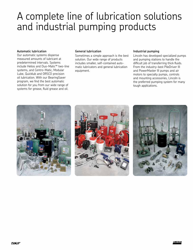
A complete line of lubrication solutions and industrial pumping products
Automatic lubricationOur automatic systems dispense measured amounts of lubricant at predetermined intervals. Systems include Helios and Duo-Matic™ two-line systems, and Centro-Matic, Modular Lube, Quicklub and ORSCO precision oil lubrication. With our BearingSaver program, we find the best automatic solution for you from our wide range of systems for grease, fluid grease and oil.
General lubricationSometimes a simple approach is the best solution. Our wide range of products includes smaller, self-contained auto-matic lubricators and general lubrication equipment.
Industrial pumpingLincoln has developed specialized pumps and pumping stations to handle the difficult job of transferring thick fluids. From the industry-best PileDriver III and PowerMaster III pumps and air motors to specialty pumps, controls and mounting accessories, Lincoln is the preferred pumping system for many tough applications.
skf.com
® SKF is a registered trademark of the SKF Group.
® Lincoln, Quicklub, Quicklinc, BearingSaver, Helios, Centro-Matic, Modular Lube, PileDriver III and PowerMaster III are registered trademarks of Lincoln Industrial Corp.
© SKF Group 2014The contents of this publication are the copyright of the publisher and may not be reproduced (even extracts) unless prior written per-mission is granted. Every care has been taken to ensure the accuracy of the information contained in this publication but no liability can be accepted for any loss or damage whether direct, indirect or consequential arising out of the use of the information contained herein.
December 2014 · FORM 442833