Leica SP8 Upright confocal microscope 14, 07, 2020
15
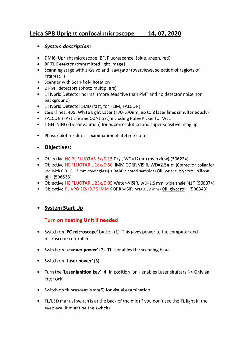
Leica SP8 Upright confocal microscope 14, 07, 2020 • System description: • DMi6, Upright microscope: BF, Fluorescence (blue, green, red) • BF TL Detector (transmitted light image) • Scanning stage with z-Galvo and Navigator (overviews, selection of regions of interest…) • Scanner with Scan-field Rotation • 2 PMT detectors (photo multipliers) • 1 Hybrid Detector normal (more sensitive than PMT and no detector noise nor background) • 1 Hybrid Detector SMD (fast, for FLIM, FALCON) • Laser lines: 405, White Light Laser (470-670nm, up to 8 laser lines simultaneously) • FALCON (FAst Lifetme CONtrast) including Pulse Picker for WLL • LIGHTNING (Deconvolution) for Superresolution and super sensitive imaging • Phasor plot for direct examination of lifetime data • Objectives: • Objective HC PL FLUOTAR 5x/0.15 Dry , WD=12mm (overview) (506224) • Objective HC FLUOTAR L 16x/0.60 IMM CORR VISIR, WD=2.5mm (Correction collar for use with 0.0 - 0.17 mm cover glass) + BABB cleared samples (Oil, water, glycerol, silicon oil)- (506533) • Objective HC FLUOTAR L 25x/0.95 Water-VISIR, WD=2.5 mm, wide angle (41°) (506374) • Objective PL APO 20x/0.75 IMM CORR VISIR, WD 0.67 mm (Oil, glycerol)- (506343) • System Start Up Turn on heating Unit if needed • Switch on ‘PC-microscope’ button (1). This gives power to the computer and microscope controller • Switch on ‘scanner power’ (2)- This enables the scanning head • Switch on ‘Laser power’ (3) • Turn the ‘Laser ignition key’ (4) in position ‘on’- enables Laser shutters (-> Only an interlock) • Switch on fluorescent lamp(5) for visual examination • TL/LED manual switch is at the back of the mic (if you don’t see the TL light in the eyepiece, it might be the switch)
Transcript of Leica SP8 Upright confocal microscope 14, 07, 2020
Leica SP8 Upright confocal microscope 14, 07, 2020
• System description:
• DMi6, Upright microscope: BF, Fluorescence (blue, green, red) • BF TL Detector (transmitted light image) • Scanning stage with z-Galvo and Navigator (overviews, selection of regions of
interest…) • Scanner with Scan-field Rotation • 2 PMT detectors (photo multipliers) • 1 Hybrid Detector normal (more sensitive than PMT and no detector noise nor
background) • 1 Hybrid Detector SMD (fast, for FLIM, FALCON) • Laser lines: 405, White Light Laser (470-670nm, up to 8 laser lines simultaneously) • FALCON (FAst Lifetme CONtrast) including Pulse Picker for WLL • LIGHTNING (Deconvolution) for Superresolution and super sensitive imaging
• Phasor plot for direct examination of lifetime data
• Objectives:
• Objective HC PL FLUOTAR 5x/0.15 Dry , WD=12mm (overview) (506224) • Objective HC FLUOTAR L 16x/0.60 IMM CORR VISIR, WD=2.5mm (Correction collar for
use with 0.0 - 0.17 mm cover glass) + BABB cleared samples (Oil, water, glycerol, silicon oil)- (506533)
• Objective HC FLUOTAR L 25x/0.95 Water-VISIR, WD=2.5 mm, wide angle (41°) (506374) • Objective PL APO 20x/0.75 IMM CORR VISIR, WD 0.67 mm (Oil, glycerol)- (506343)
• System Start Up
Turn on heating Unit if needed
• Switch on ‘PC-microscope’ button (1). This gives power to the computer and
microscope controller
• Switch on ‘scanner power’ (2)- This enables the scanning head
• Switch on ‘Laser power’ (3)
• Turn the ‘Laser ignition key’ (4) in position ‘on’- enables Laser shutters (-> Only an
interlock)
• Switch on fluorescent lamp(5) for visual examination
• TL/LED manual switch is at the back of the mic (if you don’t see the TL light in the
eyepiece, it might be the switch)

• For imaging: start LASX software. Select configuration Machine.xlhw or machine
with zgalvo and DM6microscope (You should insert zgalvo stage and fix in place
using 2 knobs at the back-> If you are not using it, place it face down in the heating
chamber!)
• !!!!! Never use "Use last system settings"
Fig.1
• In the LASX software, go to ‘configuration’ –‘lasers’- Turn ON the lasers you want to
use. Set the Laser power of the WLL to 85% and 80MHz (usually the default
numbers).
Fig.2
• make sure the pulse picker is set to 80 MHz, otherwise laser power is significantly
lower (Fig.2)
• Visual examination of the sample

• On the microscope touchpad choose the illumination icon to open the illumination
menu.
• For transmitted light press the BF/TL button and operate the TL shutter from
touchscreen (if you don’t see any light probably the manual shutter “Lever” is
closed)
• Intensity buttons are found on the left side of the microscope as well (TL indicator
light is next to it)
• For fluorescent illumination, press FLUO button in the illumination menu of the
microscope touchpad.
• Choose filter cubes on the front panel: (DAPI, GFP, RHO). Open the IL-shutter to see
fluorescence.
• Intensity buttons (same as for BF) on the left side of the microscope stand lets you
change the LED intensity
• FOCUSing on your sample- To prevent crash, look from the side and raise the
sample very close to the objective (to pass the focus point),then look in the
eyepiece and always move the stage downward until you see the sample.
• Visual illumination is disabled during scanning, the system is automatically changing
to "CS" mode. (For TL detector you need to manually switch back the “lever “at the
back of the microscope).
• Data organization
In User Config -> Your data can be organized into Folder structure or
Project based structure. In the folder based structure files are saved as
TIFF while projects are saved as Lif/Lof. (Due to a software bug do not
use Folder base file saving)
Additional info @:
file:///C:/Program%20Files/Leica%20Microsystems%20CMS%20GmbH/LAS%20X/BIN/UserH
elp/UserHelpEnglish/Default.htm?Highlight=user
configuration#DLG/Configuration/DLG_configuration_user_configuration.htm?Highlight=us
er configuration
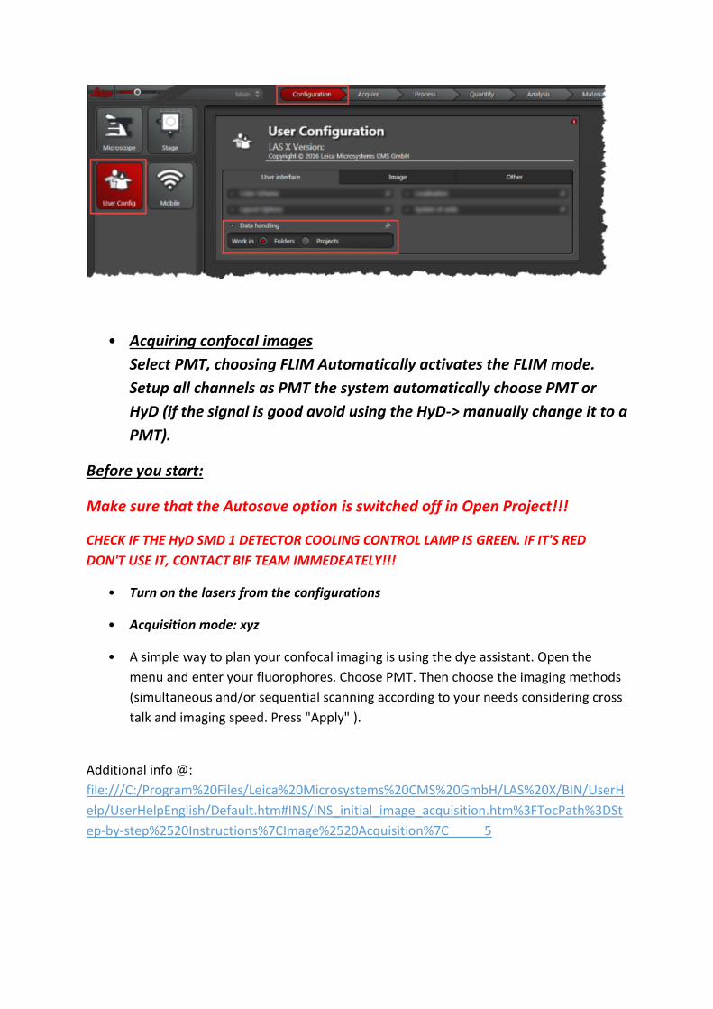
• Acquiring confocal images
Select PMT, choosing FLIM Automatically activates the FLIM mode.
Setup all channels as PMT the system automatically choose PMT or
HyD (if the signal is good avoid using the HyD-> manually change it to a
PMT).
Before you start:
Make sure that the Autosave option is switched off in Open Project!!!
CHECK IF THE HyD SMD 1 DETECTOR COOLING CONTROL LAMP IS GREEN. IF IT'S RED
DON'T USE IT, CONTACT BIF TEAM IMMEDEATELY!!!
• Turn on the lasers from the configurations
• Acquisition mode: xyz
• A simple way to plan your confocal imaging is using the dye assistant. Open the
menu and enter your fluorophores. Choose PMT. Then choose the imaging methods
(simultaneous and/or sequential scanning according to your needs considering cross
talk and imaging speed. Press "Apply" ).
Additional info @:
file:///C:/Program%20Files/Leica%20Microsystems%20CMS%20GmbH/LAS%20X/BIN/UserH
elp/UserHelpEnglish/Default.htm#INS/INS_initial_image_acquisition.htm%3FTocPath%3DSt
ep-by-step%2520Instructions%7CImage%2520Acquisition%7C_____5
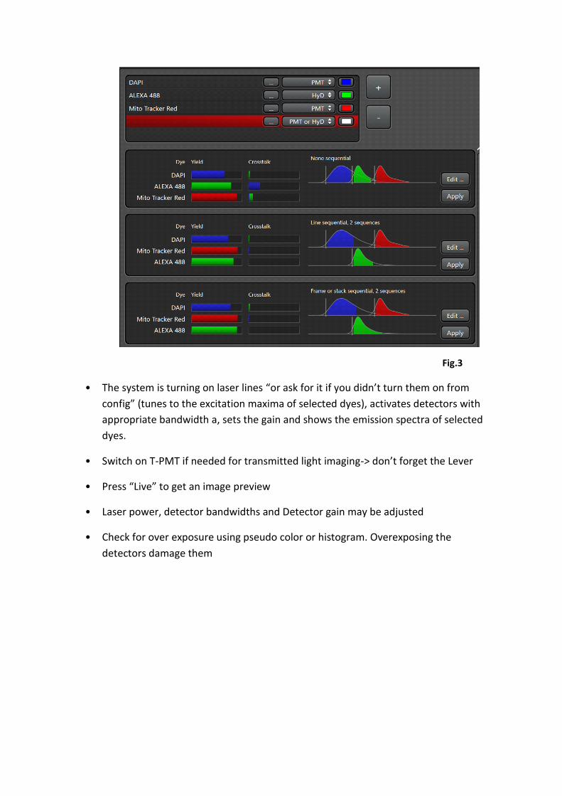
Fig.3
• The system is turning on laser lines “or ask for it if you didn’t turn them on from
config” (tunes to the excitation maxima of selected dyes), activates detectors with
appropriate bandwidth a, sets the gain and shows the emission spectra of selected
dyes.
• Switch on T-PMT if needed for transmitted light imaging-> don’t forget the Lever
• Press “Live” to get an image preview
• Laser power, detector bandwidths and Detector gain may be adjusted
• Check for over exposure using pseudo color or histogram. Overexposing the
detectors damage them

Fig.4
Set your confocal image:
!!! Note: In addition to the software (Fig4), gain, offset, scan field rotation, pinhole, zoom, and z-position settings may be changed via the control knobs in front of you
Position your sample:
Change the zoom or rotate your image -> Changing scan speed (>700 Hz ) will change the minimum zoom. Up to 600 Hz the minimum Zoom is 0.75.
Adjust the image format:
Press Nyquist (optimal) button for proper sampling
Adjust the pinhole:
Changes will alter the confocal section thickness (Refrence wavelength is set to 580nm, you can change it to your need)
And the SNR of the image; default is AU 1
Adjust your Signal to Noise ratio (SNR) by:

Applying frame or line averaging, reduces the imaging speed.
Check the pixel dwell time
• Gated detection (Useful for removing Reflection or background auto fluorescence)
Note: Only possible using HyD detectors!!!
• Used to reduce auto fluorescence or reflection with shorter lifetimes than actual fluorescence
• activate gating
• choose the detection window “in ns” for your fluorophore, adjust during live scan (reflection and Auto-fluorescence should have very short lifetimes)
• Setting up sequential scan
• Select ‘SEQ’ symbol in the ‘acquisition mode’ menu
• Select Line, Frame or Stack sequential
• Set up first configuration

• ATTENTION!!! in line sequential only PMTs and Lasers are switched on/off between
the lines (laser shutters & detector bandwidth remain the same, NO HARDWARE
MOVEMENT between lines is possible !!!)
• Press ‘+’. Set up next configuration, and so on. Set optimal imaging conditions for
each configuration.
TIP-> As an alternative you can optimize your detection/ crosstalk and channels in
line sequential mode and then duplicate the setting (press the +) and deactivate the
lasers that are not needed. This way you can reduce the crosstalk and increase the
speed of imaging.
• You can save "sequential files" in your folder and load them again.
Additional info @:
file:///C:/Program%20Files/Leica%20Microsystems%20CMS%20GmbH/LAS%20X/BIN
/UserHelp/UserHelpEnglish/Default.htm?Highlight=lineseq#INS/INS_sequential_scan
.htm?Highlight=line seq
• Setting up a Z-stack
• Joystick is always set to z-wide, if zgalvo is selected ‘Z position’ knob on the
control panel should be used for setting up the z-stack!!! Changing the
microscope focus knob/joystick will move the whole stage (z-wide)-> therefore
the z-stack will be shifted
• Acquisition mode xyz
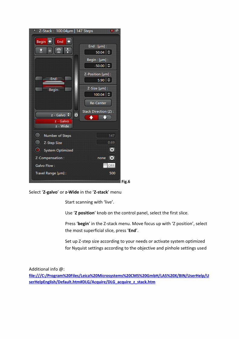
Fig.6
Select ‘Z-galvo’ or z-Wide in the ‘Z-stack’ menu
Start scanning with ‘live’.
Use ‘Z position’ knob on the control panel, select the first slice.
Press ‘begin’ in the Z-stack menu. Move focus up with ‘Z position’, select
the most superficial slice, press ‘End’.
Set up Z-step size according to your needs or activate system optimized
for Nyquist settings according to the objective and pinhole settings used
Additional info @: file:///C:/Program%20Files/Leica%20Microsystems%20CMS%20GmbH/LAS%20X/BIN/UserHelp/U
serHelpEnglish/Default.htm#DLG/Acquire/DLG_acquire_z_stack.htm
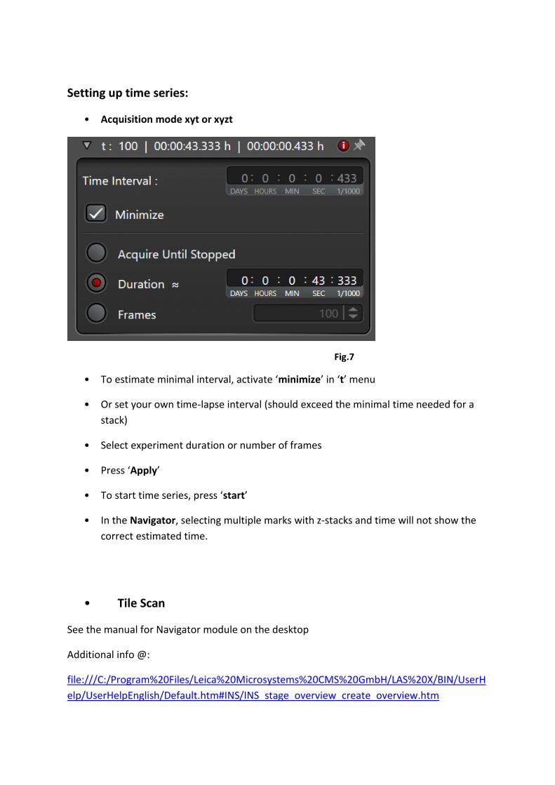
Setting up time series:
• Acquisition mode xyt or xyzt
Fig.7
• To estimate minimal interval, activate ‘minimize’ in ‘t’ menu
• Or set your own time-lapse interval (should exceed the minimal time needed for a
stack)
• Select experiment duration or number of frames
• Press ‘Apply’
• To start time series, press ‘start’
• In the Navigator, selecting multiple marks with z-stacks and time will not show the
correct estimated time.
• Tile Scan
See the manual for Navigator module on the desktop
Additional info @:
file:///C:/Program%20Files/Leica%20Microsystems%20CMS%20GmbH/LAS%20X/BIN/UserH
elp/UserHelpEnglish/Default.htm#INS/INS_stage_overview_create_overview.htm
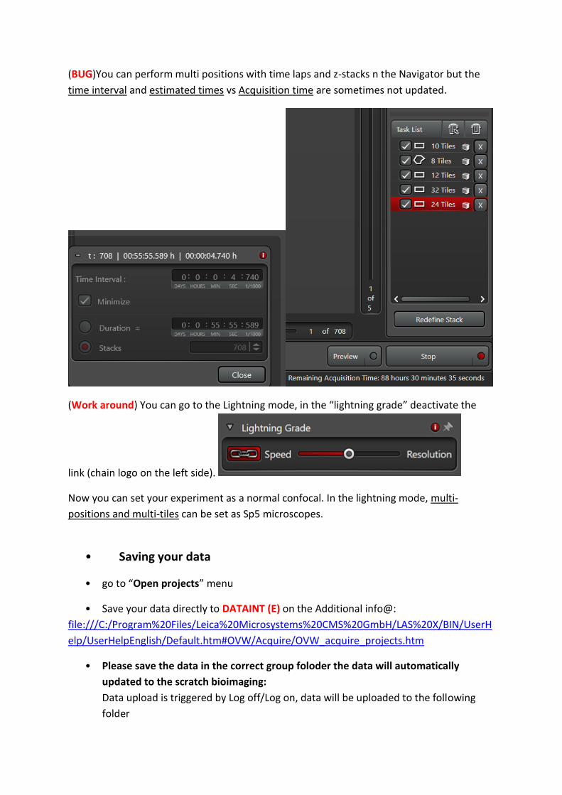
(BUG)You can perform multi positions with time laps and z-stacks n the Navigator but the
time interval and estimated times vs Acquisition time are sometimes not updated.
(Work around) You can go to the Lightning mode, in the “lightning grade” deactivate the
link (chain logo on the left side).
Now you can set your experiment as a normal confocal. In the lightning mode, multi-
positions and multi-tiles can be set as Sp5 microscopes.
• Saving your data
• go to “Open projects” menu
• Save your data directly to DATAINT (E) on the Additional info@:
file:///C:/Program%20Files/Leica%20Microsystems%20CMS%20GmbH/LAS%20X/BIN/UserH
elp/UserHelpEnglish/Default.htm#OVW/Acquire/OVW_acquire_projects.htm
• Please save the data in the correct group foloder the data will automatically
updated to the scratch bioimaging:
Data upload is triggered by Log off/Log on, data will be uploaded to the following
folder
\\scratch3.ist.local\scratch-bioimaging\{Your group Name}\_ImageDrop\
For manual upload, map the above path. login your usermane should be inserted as :
IST\username
• PLEASE NOTE: All data on our E drive are deleted after 30 days automatically!!!
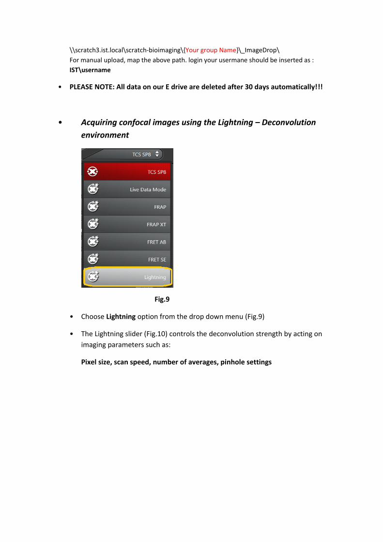
• Acquiring confocal images using the Lightning – Deconvolution
environment
Fig.9
• Choose Lightning option from the drop down menu (Fig.9)
• The Lightning slider (Fig.10) controls the deconvolution strength by acting on
imaging parameters such as:
Pixel size, scan speed, number of averages, pinhole settings

Fig.10
• Select your deconvolution Strategy: Adaptive or Global
!!! Note: In the Adaptive setting Background and bright pixels are treated
differently which might lead to non-linearity in your results (may create problems
in quantitative measurements). The Global method is treating every pixel in the
same way!!!
• Put in the embedding medium that you have used for your sample preparation
Fig.11
• To change factory deconvolution settings, go to Configuration, Lightning Tab
(Fig. 11)
• We recommend to use pinhole 0.6 AU and oversampling of 1.7
• Save your new settings under a different name and load them for imaging
• Set up your experiment, press start
• The deconvolution will start immediately online, when you have started your
experiment
• Raw data and deconvolved image will be saved as separate files in Open
project
Additional info@:
file:///C:/Program%20Files/Leica%20Microsystems%20CMS%20GmbH/LAS%20X/BIN/UserH
elp/UserHelpEnglish/Default.htm#DLG/Wizards/DLG_lightning_lightning_grade.htm
• Deconvolution processing after imaging in standard mode
• Images taken in the regular confocal environment may be deconvolved
afterwards
• select the image in Open project, then go to the Process menu→ Lightning
• put in your parameters and press “Apply”
• Switching off the system:
• Switch off lasers in the LASX software ‘Configuration’-‘lasers’ (The Laser is not off
if you just close the software!!)
• Remove your files from the project list (the next user might write data in your folder
or delete your data accidentally)
• Data upload is triggered by Log off/Log on, data will be uploaded to the following
folder
\\scratch3.ist.local\scratch-bioimaging\{Your group Name}\_ImageDrop\
For manual upload, map the above path. login your usermane should be inserted as :
IST\username
• Shut down LAS AF, shut down the computer.
• Turn the ‘Laser emission’ key (4) to the ‘off’ position
• Then switch off ‘Laser Power’ (3), ‘Scanner Power’ (2) and ‘PC/Microscope’ (1).
• Switch off the fluorescent lamp (5)
Laser Safety Instructions
• During operation of class 3B and class 4 lasers red warning lights have to be switched on manually
• Red warning light at the door of the room, containing laser-based equipment, prohibits the entrance
• Optical path of the laser beam at all setups has to stay intact and should never be disassembled by a user. Users are never permitted to disconnect optical connections (pipes, fibers etc), remove protective coverings or disassemble any parts of the setups, especially those parts that are labeled with laser-warning signs.
• User has to make sure, that objectives mounts are blocked by objectives or light- blocking plugs, before switching the system on or starting the work
• Any cleaning activities (objectives, stage cleanings) as well as changing of objectives or filters have to be performed only after blocking of the laser light is ensured. This can be ensured by closing the scanhead shutter or switching off the laser.
• Laser class-specific warnings at each setup have to be observed and considered
• Eye contact with direct beam of Class 3B laser, or eye contact with mirror reflection from class 3B laser, should be avoided at all times
• Eye or skin contact with direct or diffuse light of Class 4 laser, should be avoided at all times
• Laser safety goggles are situated at all workspaces and should be used in any situation where potential contact of eyes with Laser light of the classes 3B or 4 is possible, according to the previous two points
• Laser safety goggles have to be worn at all times of operation of Laser Class 4
• Laser safety goggles have to be worn at all times of operation laser Class 3 at the optogenetic setups
• Laser safety goggles are assigned to each setup and matched to the corresponding laser wavelengths. Matching laser safety goggles should be used at all times, and should not be carried over between the setups
• Only one person is allowed to be in the corresponding compartment during Laser Class 4 operation and optogenetic setup operation
• Users are not allowed to wear any reflective objects (rings, watches etc) during laser operation
• Using of the equipment is only allowed after the introduction from a laser safety officer of IST Austria. Introduction has to be done individually for each setup.
• Changing experimental conditions, that involves changes in the laser application, have to be reported to the laser safety officer prior to the start of experiment
Users have to understand that any violations against the instructed rules and also withholding
information leading to safety hazards will ultimately result in denial of admission to all laser equipped
instruments at the IST Austria.