Lead-cooled fast reactor (LFR) overview and perspectives · LEAD-COOLED FAST REACTOR (LFR) OVERVIEW...
9
Calhoun: The NPS Institutional Archive Faculty and Researcher Publications Faculty and Researcher Publications Collection 2009-07-14 Lead-cooled fast reactor (LFR) overview and perspectives Cinotti, Luciano Livermore, California. Lawrence Livermore National Laboratory L. Cinotti, C.F. Smith, H. Sekimoto, "Lead-cooled fast reactor (LFR) overview and perspectives," Proceedings of the Generation IV International Forum (GIF) Symposium, Paris, France, September 9-10, 2009, 8 p. http://hdl.handle.net/10945/52683
Transcript of Lead-cooled fast reactor (LFR) overview and perspectives · LEAD-COOLED FAST REACTOR (LFR) OVERVIEW...
Calhoun: The NPS Institutional Archive
Faculty and Researcher Publications Faculty and Researcher Publications Collection
2009-07-14
Lead-cooled fast reactor (LFR) overview and perspectives
Cinotti, Luciano
Livermore, California. Lawrence Livermore National Laboratory
L. Cinotti, C.F. Smith, H. Sekimoto, "Lead-cooled fast reactor (LFR) overview and
perspectives," Proceedings of the Generation IV International Forum (GIF)
Symposium, Paris, France, September 9-10, 2009, 8 p.
http://hdl.handle.net/10945/52683

LLNL-CONF-414708
LEAD-COOLED FASTREACTOR (LFR) OVERVIEWAND PERSPECTIVES
L. Cinotti, C. F. Smith, H. Sekimoto
July 14, 2009
Generation IV Intenational Forum SymposiumParis, FranceSeptember 9, 2009 through September 10, 2009

Disclaimer
This document was prepared as an account of work sponsored by an agency of the United States government. Neither the United States government nor Lawrence Livermore National Security, LLC, nor any of their employees makes any warranty, expressed or implied, or assumes any legal liability or responsibility for the accuracy, completeness, or usefulness of any information, apparatus, product, or process disclosed, or represents that its use would not infringe privately owned rights. Reference herein to any specific commercial product, process, or service by trade name, trademark, manufacturer, or otherwise does not necessarily constitute or imply its endorsement, recommendation, or favoring by the United States government or Lawrence Livermore National Security, LLC. The views and opinions of authors expressed herein do not necessarily state or reflect those of the United States government or Lawrence Livermore National Security, LLC, and shall not be used for advertising or product endorsement purposes.
Proceedings of the GIF Symposium 2009Paris, France, September 9-10, 2009
LEAD-COOLED FAST REACTOR (LFR)
OVERVIEW AND PERSPECTIVES
LUCIANO CINOTTIDel Fungo Giera Energia
P.le Cile6/2, 16036 Recco (GE), ItalyTel:+390185738721 , Fax:+390185722314 , Email:[email protected]
CRAIG F. SMITHLawrence Livermore National Laboratory
and Naval Postgraduate School1 University Circle, Monterey, CA, USA 93943
Tel: 1-831-656-2185, Fax: 1-831-656-2834, Email:[email protected]
HIROSHI SEKIMOTOTokyo Institute of Technology
2-12-1 Ookayama, Meguro-ku, Tokyo 152-8550Tel: +81 (2) 57343066, Fax: +81 (3) 57342959, Email:[email protected]
I. INTRODUCTION
The GIF Technology Roadmap [Ref 1] identified the Lead-cooled Fast Reactor (LFR) as a technology with greatpotential to meet the small-unit electricity needs of remote sites while also offering advantages as a large system for grid-connected power stations. The LFR features a fast-neutron spectrum and a closed fuel cycle for efficient conversion of fertile uranium. It can also be used as a burner of minor actinides from spent fuel and as a burner/breeder. An important feature of the LFR is the enhanced safety that results from the choice of a relativelyinert coolant. In the Roadmap, the LFR was primarily envisioned for missions in electricity and hydrogen production, and actinide management.
The application of lead technology to nuclear energy had its start in Russia in the 1970s and 80s where nuclear systems cooled by Lead-Bismuth Eutectic (LBE) were developed and deployed for submarine propulsion. More recently, attention to heavy liquid metal coolants for reactors has developed in several countries around the globe as their advantageous characteristics have gradually become recognized. This paper illustrates the technical progress achieved in the various countries.
II. LFR IN GENERATION IV
International cooperation on LFR within GIF was initiated in October 2004 and the first formal meeting of the Provisional System Steering Committee (LFR-PSSC)was held in March 2005 in Monterey, CA, USA, with
participation of representatives from Euratom, Japan, the United States and experts from the Republic of Korea. Since then, the PSSC has held regular scheduled meetings, roughly twice a year, with additional working sessions to prepare and update the draft LFR System Research Plan (SRP) [Ref 2].
The draft SRP was reviewed by the EG in mid-2007and again in mid-2008. The formal PSSC meetings weresupplemented by additional informal meetings with representatives of the nuclear industry, research organizations and universities involved in LFR development.
The preparation of a System Arrangement for approval by participating GIF members has been considered, but formal agreements are still pending.
The preliminary evaluation of the LFR concepts considered by the PSSC addresses their performance in the areas of sustainability, economics, safety and reliability, proliferation resistance and physical protection.
The designs that are currently proposed as candidates for international cooperation and joint development in the GIF framework are two pool-type reactors:
the Small Secure Transportable Autonomous Reactor (SSTAR); and
the European Lead-cooled System (ELSY).Key design data of SSTAR and ELSY are presented in Table I.
TABLE I
Proceedings of the GIF Symposium 2009Paris, France, September 9-10, 2009
Key Design data of GIF LFR concepts
Parameters/systems SSTAR ELSYPower ( MWe) 19,8 600Convertion Ratio ~1 ~1Thermal efficiency (%) 44 42Primary coolant Lead LeadPrimary coolant circulation (at power) Natural Forced
Primary coolant circulation for DHR Natural Natural
Core inlet temperature (°C)
420 400
Core outlet temp. (°C) 567 480°CFuel Nitrides MOX, ( Nitrides)
Fuel cladding material Si-Enhanced F/M Stainless
SteelT91 (aluminized)
Peak cladding temperature (°C) 650 550
Fuel pin diameter (mm)
25 10,5
Active core Heigh/ equivalent diameter (m) 0.976/1.22 0.9/4.32
Primary pumps -N° 8, mechanical, integrated in the
SG
Working fluidSupercritical
CO2 at 20MPa, 552°C
Water-superheated steam at 18 MPa,
450°CPrimary/secondary heat transfer system
N°4 Pb-to- CO2HXs
N°8 Pb-to-H2O SGs
Safety grade DHR
Reactor Vessel Air Cooling
System+
Multiple Direct Reactor Cooling
Systems
Reactor Vessel Air Cooling System
+Four Direct
Reactor Cooling Systems
+Four Secondary Loops Systems
III. SSTAR
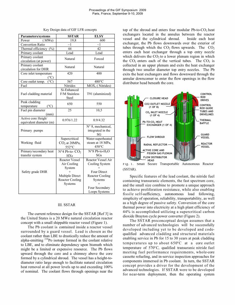
The current reference design for the SSTAR [Ref 3] in the United States is a 20 MWe natural circulation reactor concept with a small shippable reactor vessel (Figure 1).
The Pb coolant is contained inside a reactor vessel surrounded by a guard vessel. Lead is chosen as the coolant rather than LBE to drastically reduce the amount of alpha-emitting 210Po isotope formed in the coolant relative to LBE, and to eliminate dependency upon bismuth which might be a limited or expensive resource. The Pb flows upward through the core and a chimney above the core formed by a cylindrical shroud. The vessel has a height-to-diameter ratio large enough to facilitate natural circulation heat removal at all power levels up to and exceeding 100%of nominal. The coolant flows through openings near the
top of the shroud and enters four modular Pb-to-CO2 heat exchangers located in the annulus between the reactor vessel and the cylindrical shroud. Inside each heat exchanger, the Pb flows downwards over the exterior of tubes through which the CO2 flows upwards. The CO2enters each heat exchanger through a top entry nozzle which delivers the CO2 to a lower plenum region in which the CO2 enters each of the vertical tubes. The CO2 is collected in an upper plenum and exits the heat exchanger through two smaller diameter top entry nozzles. The Pb exits the heat exchangers and flows downward through the annular downcomer to enter the flow openings in the flow distributor head beneath the core.
Fig. 1. Small Secure Transportable Autonomous Reactor (SSTAR).
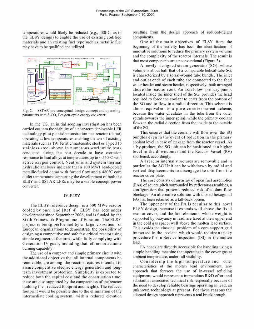
Specific features of the lead coolant, the nitride fuel containing transuranic elements, the fast spectrum core, and the small size combine to promote a unique approach to achieve proliferation resistance, while also enabling fissile self-sufficiency, autonomous load following, simplicity of operation, reliability, transportability, as well as a high degree of passive safety. Conversion of the core thermal power into electricity at a high plant efficiency of 44% is accomplished utilizing a supercritical carbon dioxide Brayton cycle power converter (Figure 2).
The SSTAR preconceptual design assumes that a number of advanced technologies will be successfully developed including yet to be developed and code-qualified advanced cladding and structural materials enabling service in Pb for 15 to 30 years at peak cladding temperatures up to about 650C at a core outlet temperature of 570C, qualified transuranic nitride fuel meeting fuel performance requirements, whole-core cassette refueling, and in-service inspection approaches for components immersed in Pb coolant. In turn, the SSTAR concept provides a driver for the development of the advanced technologies. If SSTAR were to be developed for near-term deployment, then the operating system
CLOSURE HEAD
CO2 INLET NOZZLE (1 OF 4)
CO2 OUTLET NOZZLE (1 OF 8)
Pb-TO-CO2 HEAT EXCHANGER (1 OF 4)
ACTIVE CORE AND FISSION GAS PLENUM
RADIAL REFLECTOR
FLOW DISTRIBUTOR HEAD
FLOW SHROUDGUARD VESSEL
REACTOR VESSEL
CONTROL ROD DRIVES
CONTROL ROD GUIDE TUBES AND DRIVELINES
THERMAL BAFFLE
Proceedings of the GIF Symposium 2009Paris, France, September 9-10, 2009
temperatures would likely be reduced (e.g., 480C, as inthe ELSY design) to enable the use of existing codified materials and an existing fuel type such as metallic fuel may have to be qualified and utilized.
E f f ic ie n c ie s 1 0 0 % p o w e rC y c = 4 4. 2 %N et = 4 4. 0 % 55 1 . 6 24 4 . 5 3 0 . 4 1 9 . 8
1 9 . 8 8 k g/s 4 3 8 . 1C O 2 7 . 88 3
4 0 2 . 91 9 . 9 3
P b 17 7. 81 a tm 1 9 . 9 85 6 7 . 1 4 4 . 7 8 5 . 8 9 1 7 8 . 5
T , C T , C 7 . 6 1 4 1 9 . 9 8 1 8 5. 6A ir Q , M W P , M P a 7 . 8 3 3R V A C S 1 7 7 . 4
4 1 9 . 0 0 . 3 5 . 2 1 9 . 9 8
4 2 0 . 545
3 3 . 8 5 3 1 . 2 5 8 4 . 5 8 7 . 77 . 7 7 5 7 . 4 0 0 2 0 . 0 0 7 . 7 8 3
A v e P e a k4 2 0. 0 4 20 . 0 4 9 7 . 5 6 2 7 . 7
5 3 8 . 3 6 5 0 . 0 4 . 75 5 8 . 5 6 6 8 . 9 7 5 0 0 . 0 2 3 0 . 0 3 7 . 5
2 1 0 7 kg/s 6 2 9 . 2 8 4 1 k g / s 0 . 1 2 7 0 . 1 0 16 7 %
33 %
T e m p e r a t u r e D i s t r i b u t i o n a n d H e a t B a l a n c e i n S S T A R s y s t e m .
C O R E t e m p e r a t u r e s
C o o l a n t
2 3 . 6
F u e l
2 9 . 1
7 0 . 4
C l a d d i n gB o n d
T U R B IN EH T R
C O R E
R H X
C O O L A N T M O D U L E V E S S E L
L T R
C O M P . # 1
C O M P . # 2
C O O L E R
Fig. 2. - SSTAR pre-conceptual design concept and operating parameters with S-CO2 Brayton-cycle energy converter.
In the US, an initial scoping investigation has been carried out into the viability of a near-term deployable LFR technology pilot plant/demonstration test reactor (demo) operating at low temperatures enabling the use of existing materials such as T91 ferritic/martensitic steel or Type 316 stainless steel shown in numerous worldwide tests conducted during the past decade to have corrosion resistance to lead alloys at temperatures up to ~ 550°C with active oxygen control. Neutronic and system thermal hydraulic analyses indicate that a 100 MWt lead-cooled metallic-fueled demo with forced flow and a 480°C core outlet temperature supporting the development of both the ELSY and SSTAR LFRs may be a viable concept power converter.
IV. ELSY
The ELSY reference design is a 600 MWe reactor cooled by pure lead [Ref 4]. ELSY has been under development since September 2006, and is funded by the Sixth Framework Programme of Euratom. The ELSY project is being performed by a large consortium of European organizations to demonstrate the possibility of designing a competitive and safe fast critical reactor using simple engineered features, while fully complying with Generation IV goals, including that of minor actinide burning capability.
The use of a compact and simple primary circuit with the additional objective that all internal components be removable, are among the reactor features intended to assure competitive electric energy generation and long-term investment protection. Simplicity is expected to reduce both the capital cost and the construction time; these are also supported by the compactness of the reactorbuilding (i.e., reduced footprint and height). The reduced footprint would be possible due to the elimination of the intermediate cooling system, with a reduced elevation
resulting from the design approach of reduced-height components.
One of the main objectives of ELSY from the beginning of the activity has been the identification of innovative solutions to reduce the primary system volume and the complexity of the reactor internals. The result is that most components are unconventional (Figure 3).
A newly designed steam generator (SG), whose volume is about half that of a comparable helical-tube SG, is characterized by a spiral-wound tube bundle. The inlet and outlet ends of each tube are connected to the feed water header and steam header, respectively, both arranged above the reactor roof. An axial-flow primary pump, located inside the inner shell of the SG, provides the head required to force the coolant to enter from the bottom of the SG and to flow in a radial direction. This scheme is almost equivalent to a pure counter-current scheme, because the water circulates in the tube from the outer spirals towards the inner spiral, while the primary coolant flows in the radial direction from the inside to the outside of the SG.
This ensures that the coolant will flow over the SG bundles even in the event of reduction in the primary coolant level in case of leakage from the reactor vessel. As a by-product, the SG unit can be positioned at a higher level in the downcomer and the Reactor Vessel (RV)shortened, accordingly.
All reactor internal structures are removable and in particular the SG Unit can be withdrawn by radial and vertical displacements to disengage the unit from the reactor cover plate.
The core consists of an array of open fuel assemblies (FAs) of square pitch surrounded by reflector-assemblies, a configuration that presents reduced risk of coolant flow blockage. An alternative solution with closed hexagonal FAs has been retained as a fall-back option.
The upper part of the FA is peculiar to this novel ELSY design, because it extends well above the fixed reactor cover, and the fuel elements, whose weight is supported by buoyancy in lead, are fixed at their upper end in the cold gas space, well above the molten lead surface. This avoids the classical problem of a core support grid immersed in the coolant which would require a trickyprocedure for In-Service Inspection (ISI) in the moltenlead.
FA heads are directly accessible for handling using a simple handling machine that operates in the cover gas at ambient temperature, under full visibility.
Consider ing the high temperature and other characteristics of the molten lead environment, any approach that foresees the use of in-vessel refueling equipment, would represent a tremendous R&D effort and substantial associated technical risk, especially because of the need to develop reliable bearings operating in lead, an unknown technology at present. For these reasons the adopted design approach represents a real breakthrough.

Proceedings of the GIF Symposium 2009Paris, France, September 9-10, 2009
Fig. 3. ELSY Primary system configuration.
The installation of SGs inside the reactor vessel is another major challenge of a LFR design that has been resolved by the selected approach. Particular challenges related to the operation of in-vessel SGs include the need for:
a sensitive and reliable leak detection system; a highly reliable depressurization and isolation
system.Careful attention has been also given to the issue of
mitigating the consequences of the Steam Generator Tube Rupture (SGTR) accident to reduce the risk of pressurization of the primary boundary; to this end, innovative provisions have been conceived which make the primary system more tolerant of the SGTR event.
The first provision is the elimination of the risk of failure of the water and steam collectors inside the primary boundary by installing them outside the reactor vessel. This approach aims to eliminate by design a potential initiator of a severe accident of low probability but potentially catastrophic consequences.
The second provision is the installation on each tube of a check valve close to the steam header and of a venturinozzle close to the feed water header.
The third provision aims at ensuring that the flow of any feedwater-steam-primary coolant mixture be re-directed upwards inside the SG, reducing by design the risk of propagation of large pressure waves across the reactor vessel. This occurs because the inner pressure surge itself promptly causes the closure of the normal radial coolant flow path.
The redundant, diverse Decay Heat Removal (DHR)system is provided with (i) steam condensers on the steam loops, (ii) direct reactor cooling loops with innovative lead-water dip coolers using storage water at ambient pressure and (iii) a Reactor Vessel Air Cooling System(RVACS).
The core consists of an array of 162 open fuel assemblies (FAs) of square pitch surrounded by reflector-assemblies, a configuration that presents reduced risk of coolant flow blockage. An alternative solution with closed hexagonal FAs has also been retained as a fall-back option. The core is self sufficient in plutonium and can burn its own generated minor actinides with a content at equilibrium of about 1% heavy metal.
General seismic behavior is strongly improved by the embodied technical solutions, in particular the short-heightvessel and the 2D antiseismic supports above the reactor building. Additional loads under investigation are lead sloshing resulting from seismic motion or as a result of a SGTR accident. An extensive safety analysis is also ongoing to address accidents representative of design basisconditions and of design extended conditions.
A preliminary plant Layout showing the main buildings is presented in Figure 4.
Fig. 4. - ELSY Preliminary plant layout
Fig. 4. - ELSY Preliminary plant layout
V. OTHER RELEVANT ACTIVITIES ON LFR
In addition to the ongoing activities in Europe (ELSY) and the USA (SSTAR), it is important also to recognize the ongoing LFR efforts elsewhere.
Research activities in Japan concentrate on the heat transfer performance of LBE in the intermediate loop; two phase flow characteristics of LBE in water and steam; the gas and steam lift performance of LBE; LBE-water direct contact boiling mechanism; the corrosion characteristics and corrosion behavior of the reactor coolant; the structural and cladding materials; oxygen control with steam injection into LBE; and Polonium behavior in the coolant system.
The Tokyo Institute of Technology recently proposedresearch activities on the development of Steam Lift Pump type LBE Cooled Reactors (SLPLFR), the LBE Cooled Direct Contact Boiling Water Fast Reactor (PBWFR) with electric power of 150MW [Ref 5] and on the CANDLE reactor that doesn’t require movable reactivity control mechanisms [Ref 6]. The LFR program is strongly promoted in the Center for Research into Innovative Nuclear Energy Systems. It covers not only the above
CORE
Reactor Vessel
RVACS
Steam Generator
PrimaryPumpGener
Safety Vessel

Proceedings of the GIF Symposium 2009Paris, France, September 9-10, 2009
design studies but also investigation of Polonium behavior[Ref 7], corrosion [Ref 8], and the demonstration of steam lift pumps for use in LBE [Ref 9].
Two systems are developed in the Republic of Korea, the proliferation-resistant, environment -friendly, accident-tolerant, continual and economical reactor (PEACER) [Ref 10], and the BORIS [Ref 11]. In the Russian Federation, two systems are considered: the SVBR-75/100, a LBE-cooled modular fast reactor having a power range of 75 to 100 MWe [Ref 12], and the BREST lead-cooled fast reactor concept and the associated fuel cycle [Ref 13].
VI. CONCLUSIONS
The draft SRP for the Lead-Cooled Fast Reactor has pure lead as the reference coolant and the LBE as a fall-back option. The basic approach recommended in the draft SRP portrays the dual track viability research program with convergence to a single, combined Technology Pilot Plant (TPP) leading to eventual deployment of both types of systems.
The approach adopted aims at addressing the research priorities of each participant party while developing an integrated and coordinated research program to achieve common objectives and avoid duplication of effort.
Following the successful operation of the TPP around the year 20201, a prototype independent development effort is expected for the central station LFR and the SSTAR.
The design of the industrial prototypes of the central station LFR and of the SSTAR should be planned in such a way as to start construction as soon as beginning of the TPP operation at full power has given assurance of the viability of this new technology.
ACKNOWLEDGMENTS
The work on LFR is supported by the European Commission thr o u g h t h e Euratom Framework Programmes, by the U.S. Department of Energy Generation IV Nuclear Energy System Initiative and by the Tokyo Institute of Technology.
NOMENCLATURE
DHR Decay Heat Removal 1 This is consistent with the European Sustainable Nuclear Energy Technology Platform: “Whilst the SFR remains the reference technology, two alternative technologies for fast reactors, namely the gas-cooled fast reactor (GFR) and the lead-cooled fast reactor (LFR) also need to be assessed at European level. After selection of an alternative technology, an experimental reactor in the range of 50-100 MWth will be needed to gain experience feedback by 2020 on this innovative technology”.
ELSY European Lead-cooled SystemFA Fuel AssemblyGIF Generation IV International ForumLBE Lead-Bismuth Eutectic LFR Lead-Cooled Fast Reactor ISI In-Service InspectionPSSC Provisional System Steering CommitteeRV Reactor VesselRVACS Reactor Vessel Air Cooling SystemSG Steam GeneratorSGTR Steam Generator Tube RuptureSRP System Research PlanTPP Technology Pilot Plant
REFERENCES
1. GIF-002-00, 2002. “Gen IV Technology Roadmap,” Report GIF-002-00, December 2002.
2. GIF, LFR Provisional System Steering Committee, System Research Plan for the Lead-cooled Fast Reactor (LFR), 2008.
3. Sienicki J. J. et al., “Status of development of the Small Secure Transportable Autonomous reactor (SSTAR) for Worldwide Sustainable Nuclear Energy Supply, Paper 7218, Proceedings of the International Congress on Advances in Nuclear Power Plants (ICAPP), Nice, France, 13-18 May, 2007.
4. Cinotti L., et al., “The ELSY Project”, Paper 377, Proceeding of the International Conference on the Phys ics o f Reac to r s (PHYSOR) , In te r l aken , Switzerland, 14-19 September, 2008.
5. Takahashi M. et al. , “Pb-Bi-Cooled Direct Contact Boiling Water Small Reactor”, Progress in Nuclear Energy, 47 190-201(2005).
6. Sekimoto H. et al., “Design study on small CANDLE reactor”, Energy Conversion and Management, 49[7], 1868-1872 (2008).
7. Obara T. et al., “Polonium evaporation and adhesion experiments for the development of polonium filter in lead–bismuth cooled reactors”, Progress in Nuclear Energy 50, 556-559(2008).
8. Kondo M. et al., “Corrosion of Steels in Lead-Bismuth Flow”, Journal of Nuclear Science and Technology, 43[2] 107-116(2006).
9. Takahashi M. et al. , “Study on Pb-Bi-Water Direct Contact Two-Phase Flow and Heat Transfer”, Progress in Nuclear Energy, 47. 569-576(2005).

Proceedings of the GIF Symposium 2009Paris, France, September 9-10, 2009
10. Hwang I. S., “A Sustainable Regional Waste Transmutation System: P E A C E R, Plenary Invited Paper, ICAPP ’06, Reno, NV, U.S.A., June 4-6, 2006.
11. Kim, W.J. et al., “Supercritical Carbon Dioxide Brayton Power Conversion Cycle Design for Optimized Battery-Type Integral Reactor System,” Paper 6142, Proceedings of the International Congress on Advances in Nuclear Power Plants (ICAPP), Reno, NV, USA, June 4-8, 2006.
12. Zrodnikov A. V. et al., "Use of Multi-Purpose Modular Fast Reactors SvBR-75/100 in Market Conditions," Paper 6023, Proceedings of the International Congress on Advances in Nuclear Power Plants (ICAPP), Reno, Nevada, USA, June 4-8, 2006
13. Adamov E. O. et al., Final report on the ISTC Project #1418: "Naturally Safe Lead-Cooled Fast Reactor for Large Scale Nuclear Power", Moscow 2001.
nijhuis2
Text Box
This work performed under the auspices of the U.S. Department of Energy by Lawrence Livermore National Laboratory under Contract DE-AC52-07NA27344.