Appendix 4.0 Lead-Cooled Fast Reactor - Idaho National...
28
A4-1 Appendix 4.0 Lead-Cooled Fast Reactor
Transcript of Appendix 4.0 Lead-Cooled Fast Reactor - Idaho National...

A4-1
Appendix 4.0 Lead-Cooled Fast Reactor

A4-2
Contents A4.1 INTRODUCTION AND BACKGROUND .................................................................................A4-3
A4.1.1 System Description..................................................................................................A4-3
A4.1.2 1.2 System Timeline ................................................................................................A4-4
A4.2 RESEARCH AND DEVELOPMENT STRATEGY ...................................................................A4-4
A4.2.1 Objectives ................................................................................................................A4-5
A4.2.2 Scope .......................................................................................................................A4-7
A4.2.3 Viability Issues ........................................................................................................A4-7
A4.2.4 Research Interfaces..................................................................................................A4-9
A4.2.4.1 Relationship to GIF R&D Projects................................................................A4-9 A4.2.4.2 University Collaborations ...........................................................................A4-10 A4.2.4.3 Industry Interactions....................................................................................A4-10 A4.2.4.4 I-NERI/NERI ..............................................................................................A4-10
A4.3 HIGHLIGHTS OF R&D ............................................................................................................A4-10
A4.3.1 Viability R&D for Core Neutronics ......................................................................A4-10
A4.3.2 Viability R&D for System Thermal Hydraulics ....................................................A4-11
A4.3.3 Viability R&D for Structural Design.....................................................................A4-12
A4.3.4 Viability R&D for Materials..................................................................................A4-12
A4.3.5 Viability R&D for Nitride Fuel .............................................................................A4-13
A4.3.6 Viability R&D for Passive Safety Evaluation .......................................................A4-13
A4.3.7 Viability R&D for Containment and Building Structures .....................................A4-14
A4.3.8 Viability R&D for In-service Inspection ...............................................................A4-14
A4.3.9 Viability R&D for Assessing Cost Impacts...........................................................A4-15
A4.3.10 Viability R&D for Whole-core Cassette Refueling...............................................A4-15
A4.3.11 Viability R&D for S-CO2 Brayton Cycle ..............................................................A4-15
A4.4 10-YR PROJECT COST AND SCHEDULE.............................................................................A4-16
A4.4.1 10-yr Project Budget..............................................................................................A4-16
A4.4.2 10-yr Project Schedule...........................................................................................A4-16
A4.4.3 10-yr Project Milestones........................................................................................A4-17
ADDENDUM TO LFR APPENDIX....................................................................................................A4-19
A4-3
A4.1 INTRODUCTION AND BACKGROUND
The Lead-Cooled Fast Reactor (LFR) is proposed to meet all of the Generation IV goals of non-proliferation, sustainability, safety and reliability, and economics. Two key technical aspects of the envisioned LFR that offer the prospect for achieving these goals are the use of lead (Pb) coolant and a long-life, cartridge-core architecture in a small, modular system intended for deployment with small grids or remote locations. The Pb coolant is a poor absorber of fast neutrons and enables the traditional sustainability and fuel cycle benefits of a liquid metal-cooled fast spectrum core to be realized. Lead does not interact vigorously with air, water/steam, or carbon dioxide eliminating concerns about exothermic reactions. It has a high boiling temperature (1740°C) such that the prospect of boiling or flashing of the ambient pressure coolant is realistically eliminated. Two land prototypes and ten submarine reactors utilizing lead-bismuth eutectic coolant were operated in Russia providing about 80 reactor years of experience together with the supporting development of coolant technology and control of structural material corrosion.
The LFR envisioned in the Generation IV Program is the Small Secure Transportable Autonomous Reactor (SSTAR) concept, which is a small modular fast reactor. The main mission of the 20-MWe (45 MWt) SSTAR is to provide incremental energy generation to match the needs of developing nations and remote communities without electrical grid connections, such as those that exist in Alaska or Hawaii, island nations of the Pacific Basin (e.g., Indonesia), and elsewhere. This may be a niche market within which costs that are higher than those for large-scale nuclear power plants are competitive. Design features of the reference SSTAR include a 20-to-30-yr-lifetime sealed core, a natural circulation primary, autonomous load following without control rod motion, and use of a supercritical CO2 (S-CO2) energy conversion system. The incorporation of inherent thermo-structural feedbacks imparts walk-away passive safety, while the use of a sealed, cartridge core with a 20-year or longer cycle time between refueling imparts strong proliferation resistance. If these technical innovations can be realized, the LFR will provide a unique and attractive nuclear energy system that meets Generation IV goals.
A4.1.1 System Description
The SSTAR concept utilizes transuranic nitride fuel enriched to nearly 100% in N15 in a compact core. Heat is removed from the core and transported to in-vessel Pb-to-CO2 heat exchangers by single-phase natural circulation of the Pb coolant – the need for main coolant pumps is eliminated. The fast spectrum core with nitride fuel and Pb coolant has strong reactivity feedbacks that enable autonomous load following and provide passive power shutdown in the event of loss-of-normal heat removal. The core has a long lifetime/refueling interval of 20 years during which access to the core is restricted providing proliferation resistance; the transuranic fuel is self-protective in the safeguards sense. The Pb coolant and nitride fuel provide for enhanced passive safety whereby the core and in-reactor heat exchangers remain covered by ambient pressure single-phase primary coolant inside the reactor vessel, and single-phase natural circulation removes the core power under all operational and postulated accident conditions. The reference SSTAR reactor system is coupled to a S-CO2 gas turbine Brayton cycle power converter that enables potential improvements and cost savings over the traditional Rankine saturated steam cycle including higher cycle efficiency at temperatures attainable with Pb primary coolant and nitride fuel (650°C peak cladding temperature and 561°C core outlet temperature for a 405°C inlet temperature) as well as a smaller plant footprint with simpler secondary side components.
The SSTAR reference reactor system fits inside of a reactor vessel that is about 18 m tall and 3.2 m in diameter; small enough to be transported by either rail or barge. The compact ~1.0 m diameter/0.8 m height active core is located near the bottom of the vessel. Large diameter (2.7 cm) fuel pins are arranged on a triangular pitch. The core is not composed of individual removable assemblies but is a single

A4-4
proliferation resistant cassette that can be accessed only when refueling equipment is brought to the site at the end of the core lifetime. The fuel pins consist of transuranic nitride (enriched to nearly 100% N15) pellets bonded by molten Pb to the silicon-enhanced ferritic-martensitic stainless steel cladding. A short fission gas plenum (about one-fourth of the active core height) is provided at the top of each fuel pin. The molten Pb coolant flows upwards through the core and the overlying riser region inside of a cylindrical shroud. Near the free surface at the top of the Pb, the coolant enters modular Pb-to-CO2 heat exchangers located in the annulus between the shroud and reactor vessel to flow downwards over the exterior of double-walled tubes containing the upwards flowing CO2. The Pb continues through the downcomer region beneath the heat exchangers and enters the lower plenum below the core where a flow distributor tends to equalize the pressure at the core inlet. The Pb flow is driven solely by natural circulation – key is the low core pressure drop reflecting a large coolant hydraulic diameter and short fuel pin height. The Pb coolant enters the core at 405°C (providing adequate margin above the Pb freezing temperature of 327°C) and exits the core at a 561°C mixed mean outlet temperature. The maximum temperature at the cladding inner surface is 650°C. Corrosion control is maintained through the formation and maintenance of protective oxide (Fe3O4 at lower temperatures) layers upon the steel structural surfaces through maintenance of the dissolved oxygen potential in the Pb coolant. Shutdown rods provide for startup and shutdown while compensation rods offset small reactivity changes during the 20-year core lifetime; control rods are not needed to effect power changes during autonomous load following due to the strong reactivity feedbacks of the fast spectrum core. The reactor vessel is surrounded by a guard vessel. The exterior of the guard vessel is passively cooled by upward flowing air driven by natural convection; passive air-cooling provides for emergency heat removal in the event that neither the normal operational nor shutdown heat removal paths are available. The reactor system is coupled to an S-CO2 power converter. Supercritical CO2 at 20 MPa pressure is heated to 541°C in the in-reactor Pb-to-CO2 heat exchangers. It expands to about 7.4 MPa in a remarkably small turbine that drives the generator and then passes through two recuperators (a high temperature recuperator followed by a low temperature recuperator) where a portion of the remaining thermal energy is extracted to preheat the compressed CO2 that is returned to the in-reactor heat exchangers. Upon exiting the low temperature recuperator, about 67% of the CO2 passes through the cooler where heat is rejected from the cycle and the CO2 is cooled to 31.25°C, compressed in a small compressor to 20 MPa, and preheated in the low temperature recuperator. The remaining 33 % of the CO2 is directly recompressed in a second compact compressor and merged with the other flow stream between the low and high temperature recuperators. This flow split/merge approach is necessitated by the significantly greater specific heat of the higher pressure CO2 over the temperature range of the low temperature recuperator. The recuperators and cooler incorporate printed circuit heat exchangers (PCHEs) to further reduce component volumes. The cycle efficiency of 44% provides about 20 MWe of electricity for 45 MWt of core thermal power.
A4.1.2 1.2 System Timeline
The schedule proposed for LFR development is illustrated in Section 4.2. The plan described in this section reflects 10 years of a 20-year development program leading to startup of a LFR demonstration unit. Key dates in the current 10-year plan include a fast reactor option selection in 2010 and a decision in 2014 whether to proceed to construction of the LFR demonstration plant.
A4.2 RESEARCH AND DEVELOPMENT STRATEGY
The LFR development strategy incorporates a near-term focus on the technologies for a small, simple modular design for specialized markets. Targeting this market need offers an additional benefit of manageable research and development (R&D) and demonstration costs. If market conditions motivate it, the technology base can be applied later to larger LFR concepts as needed to support a long-term sustainable fuel cycle. Current and near-term R&D is planned to address key viability issues leading to

A4-5
the 2010 decision, while subsequent R&D will address issues leading to demonstration of the LFR concept.
A4.2.1 Objectives
LFR viability R&D objectives can be grouped according to two purposes:
1. Objectives demonstrating the viability of LFR/SSTAR features to meet all of the Generation IV goals
2. Objectives demonstrating the viability of satisfying requirements for a commercial LFR/SSTAR nuclear power plant that meets all of the Generation IV goals.
Objectives directly related to meeting each of the Generation IV goals are as follows:
• Sustainability-1 (S-1) and Sustainability-2 (S-2). Analyses indicate that the LFR with a fast neutron spectrum core with transuranic nitride fuel and Pb coolant is fissile self sufficient with a core conversion ratio of unity. This enables a closed fuel cycle in which there is a fertile feed stream of depleted or natural uranium and a minimal volume waste stream comprised only of fission products. All fissile material including minor actinides can be recycled in the fabrication of new fuel cores and burned as fuel in reactors. Objectives are to confirm the viability of these attributes.
• Economics-1 (E-1). Overnight and generation costs remain to be estimated. Objectives are to demonstrate the viability of reducing costs by taking advantage of LFR system attributes that enable savings such as system simplification through elimination of the need for an intermediate heat transport circuit; elimination of main coolant pumps; autonomous load following that simplifies the control system and reduces operator requirements; utilization of S-CO2 Brayton cycle power conversion that offers higher plant efficiency together with smaller, simpler, and fewer balance of plant components; small plant footprint; factory fabrication that reduces component costs; and modular transport and installation at the site that reduces construction time and costs.
• Economics-2 (E-2). Financial risk remains to be quantified. The small modular plant requires a smaller outlay of funds and provides a shorter construction time. When the plant goes online, it becomes a source of positive cash flow that can be applied to financing the construction of the next module and so on. An objective is to establish the viability of this approach. An economic objective of passive safety is to demonstrate the viability of minimizing the threat to investment in the plant due to postulated accidents or sabotage.
• Safety and Reliability-1 (SR-1). Objectives are to show the viability of taking advantage of the highly favorable LFR attributes, including Pb coolant properties (inertness with respect to interactions with CO2, water/steam, and air; high boiling temperature), properties of nitride fuel (compatibility with cladding, bond, and coolant; high melting temperature; high decomposition temperature; large thermal conductivity), natural circulation heat transport at power levels exceeding 100% nominal, and large reactivity feedbacks from the fast spectrum core that provide passive power reduction to achieve “Walk-Away” passive safety.
• Safety and Reliability-2 (SR-2). Indications are that the SSTAR core and heat exchangers will remain covered by ambient pressure, single-phase primary coolant inside the reactor vessel and single-phase natural circulation will remove the core power under all operational

A4-6
and postulated accident conditions. Objectives are to show that it is viable to ensure that this is the nominal behavior, and to show that it is viable to ensure that scenarios that could conceivably result in core damage such as the simultaneous penetration of both the reactor vessel and guard vessel have an extraordinarily low probability.
• Safety and Reliability-3 (SR-3). Objectives are a viable licensing approach that effectively uses “Walk Away” passive safety and a very low likelihood of core damage to eliminate the licensing need for offsite emergency response. A specific objective is the acceptance of passive safety as a barrier in the defense-in-depth approach that is a bedrock principle of licensing to argue for elimination of the need for emergency planning.
• Proliferation Resistance and Physical Protection-1 (PR-1). The transuranic fuel is self-protective in the safeguards sense. Objectives are to establish the viability of achieving a very long core lifetime (which has been shown to be neutronically viable) together with the viability of design measures to restrict access to the fuel or neutrons, to effectively refuel the core and transport it in a coolable and shielded state while maintaining a high resistance to theft, and to provide a plant that is resistant to sabotage or malevolent human-induced acts (e.g., airplane crashes).
Table A4.1 summarizes how specific features of the LFR/SSTAR system can contribute to satisfaction of all of the Generation IV goals. Table A4.2 summarizes how specific requirements for the LFR/SSTAR system can contribute to satisfaction of all of the Generation IV goals.
Table A4.1. Contribution of Specific LFR/SSTAR Features to Meeting of Generation IV Goals LFR Features S-1 S-2 E-1 E-2 SR-1 SR-2 SR-3 PR-1
Pb Properties + + + + + + +
Nitride Fuel Behavior + + + + +
Fast Spectrum Core-Long Core Lifetime + + +
Fast Spectrum Core-Unity Conversion Ratio + + + + +
Fast Spectrum Core-Burnup Reactivity Swing < 1 $
+ + + + +
Fast Spectrum Core-Large Reactivity Feedbacks
+ + + + +
Simplification-Elimination of Intermediate Heat Transport System
+ + + + +
Simplification-Natural Circulation Primary Coolant Heat Transport
+ + + + +
Passive Safety + + + + +
Transuranic Fuel-Self Protection + +
Supercritical Carbon Dioxide Brayton Cycle Power Conversion
+ +
Small Power Level-20 MWe (45 MWt) to 100 MWe
+ +
Factory Fabricability + +
Full Transportability and Modular Assembly and Installation at Site
+ +

A4-7
Table A4.2. Contribution of Specific LFR/SSTAR Requirements to Meeting of Generation IV Goals LFR Features S-1 S-2 E-1 E-2 SR-1 SR-2 SR-3 PR-1
Proliferation Resistance +
Small Power Level-20 to 100 MWe + +
Economical Overnight Capital and Generation Costs; Niche Market Conditions
+ +
“Walk Away” Passive Safety + + + + +
Autonomous Operation + + + + +
Fissile Self Sufficiency + + + + +
Reactor Compatible with Advanced Energy Conversion
+ +
Small Power Level-20 MWe (45 MWt) + +
Factory Fabrication of All Reactor and Balance of Plant Components
+ +
Full Transportability and Modular Assembly and Installation at Site
+ +
Efficient Fuel Utilization + + + +
60-Year Plant Lifetime + +
Plant Licensable by U.S. NRC + + +
Near Worldwide Deployable + + + + + + +
In-Service Inspection + + + + +
Flexibility to Generate Other Energy Products-Desalinated Water
+ +
A4.2.2 Scope
This R&D plan will address viability issues associated with the LFR leading to the Generation IV fast reactor selection in 2010 and a follow-on decision in 2014 to proceed with design and construction of the LFR demonstration plant. Viability will be established through focused viability R&D tasks and with formulation of a technically defensible preconceptual design. Conceptual design will begin in 2009 and continue, given a decision for pursuing the LFR in 2010, to 2014. R&D tasks that support conceptual design will be defined in more detail at a later time in the viability R&D program, but will include analysis and experiments intended to reduce design uncertainty and to establish conceptual limiting conditions of operation.
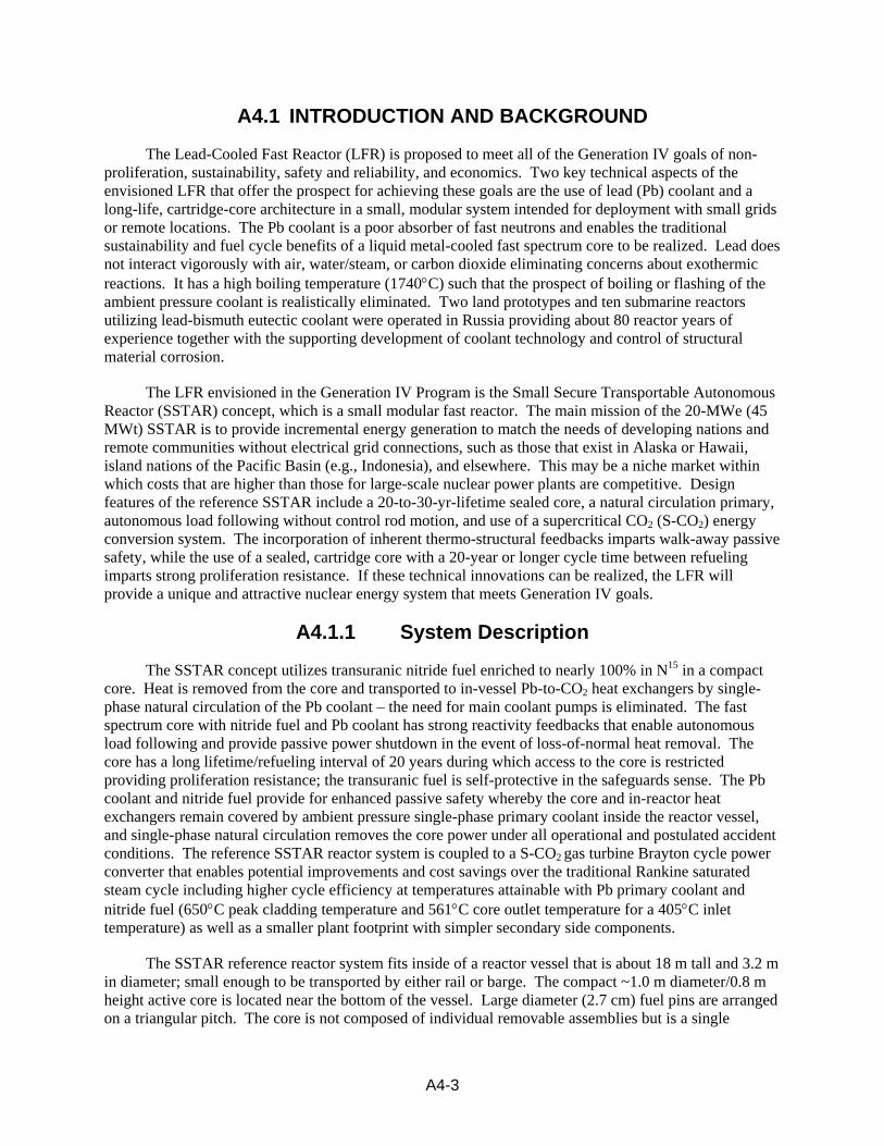
A4.2.3 Viability Issues
Viability issues for the LFR as listed topically as follows, and are also described further in Section A4.3.
• Core Neutronics
– Fuel conversion sufficient to sustain a 20 – 30-year-life core – Identification of core parameters that provide feedback coefficients, that ensure passive
safety, and autonomous load following viability
A4-8
• System Thermal Hydraulics
– Natural circulation within core parameter constraints necessary to meet conversion and thermo-structural feedback requirements
– Thermal response to feedbacks to ensure passive safety and autonomous load following – Feasibility of elimination of an intermediate loop – Identification of Pb-S-CO2 heat exchanger parameters – Safety issues arising from S-CO2 tube rupture, and identification of mitigation concepts – Concepts for passive decay heat removal
• Structural Design
– Stress and temperature conditions for structural materials are compatible with expected materials performance
• Materials
– Materials structural reliability in the anticipated service environment (i.e., high temperature Pb in a fast neutron flux)
– Materials compatibility with and corrosion behavior from high-temperature Pb – Conditions of operation required for ensuring materials integrity and compatibility are
practically achievable in an operating plant
• Nitride Fuel
– Uranium nature and TEU nitride compatibility with Pb at elevated temperatures – High-burnup potential of nitride fuel during an extended core life is not yet established – Transient behavior must be shown to not exacerbate off-normal events
• Passive Safety Characteristics
– Thermo-structural feedback coefficients required to ensure passively safe response must be practically achievable
– Decay heat removal after accidents must be sufficient to prevent core damage – Pb-S-CO2 heat exchanger tube rupture must not prevent heat removal from the core or
introduce positive reactivity insertion
• Containment and Building Structures
– Containment necessary to prevent release to environment must be small enough to reduce economy of scale penalty
– Containment necessary to prevent release to environment must allow a path for passive removal of decay heat

A4-9
• In-service Inspection
– Reactor vessel and safety system integrity in the vessel sealed for 20 to 30 years must be verified using a viable and practical means
• Cost Impacts
– Design features to achieve necessary safety and proliferation resistance must not impact capital costs to render the LFR uneconomic for the envisioned deployments
– Operating strategy must be compatible with requirements to ensure operating costs are acceptable for the envisioned deployments
– Cost-essential design features must identified to ensure compatibility with design for performance
• Whole-core Cassette Refueling
– Concepts for safe and secure refueling must be identified and must be practical – Shielding and cooling of a spent core must be practically achievable – Design features to allow refueling must not add significantly to capital cost and must not
compromise safety of containment
• S-CO2 Brayton Cycle Energy Conversion
– The energy conversion system must be reliable – The smaller, innovative conversion plant components envisioned must be determined to
be feasible
A4.2.4 Research Interfaces
The LFR R&D program interfaces with a number of domestic and international partners, as described below. In addition, the current LFR concept calls for use of a supercritical CO2 energy conversion system, and this plan assumes that the U.S. Generation IV Energy Conversion R&D will address development needs of that technology. However, the LFR program will identify and address aspects of supercritical CO2 energy conversion that are specific to the LFR.
A4.2.4.1 Relationship to GIF R&D Projects
The initial LFR Steering Committee interest includes Euratom, Japan, and possibly South Korea.
LFR R&D activities in Europe are proceeding mainly in the frame of ADS development. A group of 29 organizations plus many universities has presented to the European Community the IP EUROTRANS project to develop a preliminary design for a European Facility for Industrial Transmutation. A group of 12 organizations, in the EoI on the European Lead Fast Reactor related to the 6th EURATOM Reactor Technology Development Programme, have stated their interest in a medium-size (600 MWe) lead cooled, forced convection fast reactor.
Work with Japan includes cooperation on topics common to small modular fast reactors, with focus on lead coolant in the U.S. and sodium coolant in Japan. Periodic coordination meetings are held with Central Research Institute for Electric Power Industry (CRIEPI) and Toshiba. In addition, technical

A4-10
collaborations and information exchanges with the Japanese Atomic Energy Research Institute, Japan Nuclear Cycle Development Institute (JNC), and the Tokyo Institute of Technology exist.
Although Russia is not currently part of the GIF, there has been a long history of cooperation with Russian lead-bismuth reactor technology experts, in particular, IPPE and Gidropress. Several on-going ISTC projects support further development of coolant technology and materials.
A4.2.4.2 University Collaborations
The University of California - Berkeley has been a long-standing member of the LFR research and development community with contributions in innovative core and component design and analysis.
In fiscal year 2004, a Ph.D. candidate at Ohio State University, began working on a two-year Department of Energy (DOE) Nuclear Engineering Graduate Fellowship in collaboration with Argonne National Laboratory on the development of an approach for cooling of a LFR spent cassette core during refueling and transport.
Partnership in material science topics includes work with Massachusetts Institute of Technology, University of Nevada at Las Vegas, University of Illinois, and University of Wisconsin.
A4.2.4.3 Industry Interactions
In addition to work with Toshiba via CRIEPI, initial discussions on potential cooperation have been held with General Electric and Westinghouse.
A4.2.4.4 I-NERI/NERI
A U.S. DOE/Euratom Joint I-NERI, “Lead Fast Reactor Engineering and Analysis,” has commenced between Argonne National Laboratory and the Joint Research Center of the European Commission, Institute for Energy, Petten, the Netherlands.
There is an on-going I-NERI between Los Alamos National Laboratory and the Korea Atomic Energy Research Institute (KAERI) and Seoul National University of the Republic of Korea on fuel cladding materials development and testing as well as improved oxygen sensors. The Republic of Korea program, PEACER, is developing a LBE-cooled transmutation reactor.
A proposed I-NERI with JNC will examine Oxide Dispersion Strengthened steel irradiation performance and compatibility with lead-alloys.
A NERI Project, 02-065, “Coupling of Lead-Cooled, Closed Fuel Cycle Fast Reactors to Advanced Energy Converters,” is ongoing in its final year at Argonne National Laboratory and Oregon State University.
A4.3 HIGHLIGHTS OF R&D
A4.3.1 Viability R&D for Core Neutronics
Motivation: Core design is essential to establishing the necessary features of a 20 – 30-year-life core, and to determine core parameters that impact feedback coefficients, which are essential inputs for establishing passive safety and autonomous load-following viability.

A4-11
Tasks:
• Further optimize the core configuration
– Determine the size of the central low enrichment zone to reduce radial power peaking and improve time-dependent conversion behavior for the long-life core strategy
• Startup/shutdown rod and control rod strategy
– Includes assessing number and location of rods – Satisfying diversity and redundancy requirements
• Calculate reactivity feedback coefficients
– To support autonomous load following evaluation – To support passive safety evaluation
A4.3.2 Viability R&D for System Thermal Hydraulics
Motivation: Studies of system thermal hydraulics are essential to establish the parameters for potential natural circulation cooling in the primary system, for identifying any safety issues to be addressed in subsequent design, and to establish parameters for ensuring passively safe response.
Tasks:
• Autonomous load following evaluation for reactor using the calculated reactivity feedback coefficients
– Determine need for any enhancement of core radial expansion feedback – Develop and evaluate preconceptual control strategy for S-CO2 Brayton cycle
• Viability of elimination of intermediate heat transport system
– Evaluate effect of tube rupture in Pb-to-CO2 HX and blowdown of CO2 into reactor system
– Develop pressure relief strategy for reactor coolant system – Evaluate need to contain CO2 and entrained radionuclides released from reactor coolant
system – Assess impact upon containment configuration, size, capability, and other requirements – Viability of failure-resistant HX concepts
• Viability of startup using natural circulation
– Evaluate possible need for small flow assist during startup or shutdown – Assess options for startup flow: mechanical, electromagnetic, lift (noncondensable gas
injection), or jet pumps

A4-12
• Viability of emergency heat removal concept
– Safety grade system – Performance of passive air cooling of outside of guard vessel – Relative merits of alternate in-reactor cooling systems (e.g., DRACS or IRACS) versus
reactor vessel air cooling system approach – performance, reliability, cost, resistance to attack or sabotage
– Final selection of emergency heat removal approach
A4.3.3 Viability R&D for Structural Design
Motivation: Viability of the long-life core and passive safety under all upset conditions (including seismic events that might unacceptably reconfigure a core) requires materials that can withstand stresses at high temperature and, for some components, contact with liquid lead. The range of expected stresses and temperatures and potential materials must be identified. Establishing actual materials and conditions of operation are design functions to be accomplished later in a development program. However, ranges of conditions must be identified to provide requirements for materials and to determine that such material performance can be achieved within an engineering development program.
Tasks:
• Evaluate preconceptual structural design to ensure viability at projected system temperatures up to 650°C peak cladding
– Identify suitable structural materials for core, in-vessel structures, reactor, and guard vessels using the materials at projected system temperatures
– Evaluate concepts for core support, core clamping, and restraint (the heavier coolant may require a new strategy for prevention against floating and ejection of components)
– Evaluate effect of seismic requirements on structures including reactor and guard vessel thicknesses
A4.3.4 Viability R&D for Materials
Motivation: Prior experience with heavy liquid metals and with fast reactors indicates that materials of construction will be challenged in the envisioned LFR environments. Viability of long core lifetime, passive safety, and economic performance (both capital and operating costs) will depend upon identifying materials with the potential to meet service requirements.
Tasks:
• Identification of candidate Si-enhanced ferritic-martensitic (F/M) steels, ODS F/M steels, carbides, amorphous materials, and other candidate materials
• Compatibility testing of candidate materials with heavy liquid metal coolants
• Demonstration of control of corrosion to assure adequate thickness of cladding and structural elements at operating temperatures over long core and reactor lifetimes

A4-13
• Code cases need to be prepared for selected cladding and structural materials throughout the operating temperature range
A4.3.5 Viability R&D for Nitride Fuel
Motivation: Achieving long core life, walk-away passive safety, and reliable operation will require robust and predictable fuel performance for long durations under service conditions. Nitride fuel has many properties and characteristics that render it well suited for LFR application; however, there is very little data with nitride fuel performance to confirm the designer’s current assumptions regarding this fuel type. In addition, although operation with failed fuel must be a low-probability circumstance, it must be accommodated, so sufficient compatibility of irradiated nitride fuel with lead at high temperatures must be demonstrated
Tasks:
• Irradiation testing and demonstration must be performed to projected burnups (> 13 at %) under operating conditions
– Includes transuranic nitride with volatile minor actinide constituents
• Transient testing including accident conditions to verify acceptable fuel behavior
A4.3.6 Viability R&D for Passive Safety Evaluation
Motivation: Passively safe response can be designed into the reactor core and plant based on current experience and passive safety design principles. However, the magnitudes of feedback coefficients for a given design and integral behavior of a reactor plant must be verified through further analysis. It is anticipated that some coefficients may require enhancement through design modification, and those design impacts must be determined acceptable at the preconceptual level through follow-on analysis. Eventually, inherent response of components (i.e., the magnitude of the coefficients for a certain design configuration) must be verified with single-effect experiments and through integral testing and demonstration with a reactor plant. These experimental tasks, however, are not necessary for the viability phase.
Tasks:
• Evaluation of operational transients and postulated accidents
– Application of coupled thermal hydraulics-neutron kinetics plant dynamics analysis code – Modeling of both reactor system and S-CO2 Brayton cycle
• Evaluation of potential for flow instability
• Evaluation of potential for flow reversal
• Calculations demonstrating that core and Pb-to-CO2 heat exchangers remain covered by ambient pressure single-phase primary coolant inside the reactor vessel and single-phase natural circulation removes the core power under all operational and postulated accident conditions

A4-14
• Evaluation of removal of afterheat during postulated accidents
A4.3.7 Viability R&D for Containment and Building Structures
Motivation: Use of a small, closely coupled containment is essential for reducing the per-MW capital cost of the LFR. Experience with LWRs and previous fast reactor plants and concepts indicates that large containments necessary to contain a fair amount of gaseous reaction and fission products drove such plants to large economies of scale. This simply has to be avoided if the LFR is to be financially viable. Therefore, the factors that would drive containment design must be evaluated as part of a viability R&D program to ensure that the design, if technically achievable, can avoid large-size containment requirements.
Tasks:
• Evaluation of requirements for containment
– Determine ranges of radionuclide contents generated in coolant or released to coolant from postulated failed cladding
– Assess potential need to contain CO2 and entrained radionuclides released from reactor coolant system
• Evaluation of containment configuration, size, and capability
– Determine external events for consideration – Evaluate need for and conceptual design of decay heat removal system for postulated
accidents
• Consider industrial health aspects of operation with Pb and CO2
– CO2 release – Heavy gas asphyxiant
• Identify decontamination and decommissioning issues that would impact design
A4.3.8 Viability R&D for In-service Inspection
Motivation: Twenty-to-thirty-year operation of a plant with a sealed core will require a means of inspection and verification of key safety structures and boundaries. If such integrity cannot be verified, then the LFR concept is not likely to be licensed. Therefore, concepts for inspection and verification (in-service inspection [ISI]) must be identified during the viability R&D phase for subsequent engineering development.
Tasks:
• Identify ISI approaches for operation over long core lifetimes of 20 years or more; or
• Propose and evaluate approaches (e.g., robust core support) that significantly reduce or minimize the requirements for ISI
• Assess capability to operate with failed cladding over long core lifetime
A4-15
A4.3.9 Viability R&D for Assessing Cost Impacts
Motivation: Because the envisioned LFR concept will not have a benefit of economy of scale, the identified opportunities to reduce capital and operating costs below those of larger, base-load plants must be evaluated. In particular, additional design features with strong costs impact must be identified and considered for subsequent changes to design requirements. The Generation IV methodology will be used for assessment of LFR cost issues, in comparison with previously evaluated plants, such as the Advanced Liquid Metal Reactor.
Tasks:
• Basis for credible estimate of plant costs
– Estimate of plant capital and generation cost factors, with consideration of LFR-specific attributes (e.g., experience with factory construction of modules, etc.)
– Accounting for benefits of design simplification, passive safety, factory fabrication, modular assembly, reduced construction time at site, and reduced staffing
– Accounting for potential benefits of supercritical carbon dioxide Brayton cycle power conversion
• Evaluation of economic conditions for niche market applications
A4.3.10 Viability R&D for Whole-core Cassette Refueling
Motivation: If the LFR system as envisioned is to be viable, with refueling occurring only on 20-to-30-year intervals and with equipment that is brought onsite temporarily rather than maintained onsite, then credible concepts for emplacing and exchanging fueled core cartridges must be proposed and considered. Preconceptual designs for such systems and identification of the requirements those systems would place on the reactor primary system as well as the containment and buildings must be evaluated.
Tasks:
• Determination of viability of cooling spent cassette during retrieval and shipment following short cooldown period
• Identification of spent-fuel-cassette shielding concepts
• Evaluation of in-cask cassette cooling concepts
• Evaluation of safeguards considerations
• Impact upon plant containment and building structures
A4.3.11 Viability R&D for S-CO2 Brayton Cycle
Motivation: Use of an S-CO2 Brayton cycle for energy conversion offers the prospect of acceptable efficiencies with lower Pb coolant outlet temperatures, which reduces the challenges for materials in an economically acceptable system. Furthermore, the economic viability of the LFR may depend on reduction of capital cost achieved by incorporation of an S-CO2 Brayton cycle rather than a steam Rankine cycle. Therefore, several R&D tasks associated with S-CO2 Brayton cycle conversion are

A4-16
identified as viability tasks. Some of these tasks are expected to be addressed as part of Generation IV Energy Conversion R&D, but LFR-specific issues involving impact on reactor operation and design and heat exchange with lead coolant will be considered as part of the LFR scope.
Tasks:
• Determine whether there is information available regarding commercial-scale S-CO2 Brayton cycle operation
• Evaluate innovative design concepts for compressors, turbine, PCHEs, and other components
• Demonstrate long-term operation of components with small channels (e.g., PCHEs) without fouling or corrosion
• Demonstrate operation of an integral cycle at sufficiently large scale
A4.4 10-YR PROJECT COST AND SCHEDULE
The time and resources to conduct the planned R&D to prepare the LFR technology and design for Gen-IV down-select, and provide a basis for a decision to proceed with a prototype construction is shown below with known budgets for FY-05 and required budgets in later years.
A4.4.1 10-yr Project Budget
The known and proposed budget for the LFR R&D described in the previous sections is provided in Table A4.2.
Table A4.3. Known and Proposed Budget for U.S. LFR R&D Technology FY-05 FY-06 FY-07 FY-08 FY-09 FY-10 FY-11 FY-12 FY-13 FY-14 TOTAL System Design & Evaluation
536
Materials 754 Energy Conversion 0
Fuels & Licensing 0
Total 1317
A4.4.2 10-yr Project Schedule
The schedule proposed for LFR development is illustrated in Figure A4.1. If there is sufficient interest in an earlier demonstration than that identified in the current Generation IV schedule, then a Critical Decision-driven schedule for a demonstration project can be prepared. However, the plan described in this appendix reflects a 10-year development of the technical basis for a Gen-IV down-select and decision on whether to proceed to construction of a LFR demonstration.
• Lead engineering facility design/construction is scheduled to begin in 2006.

A4-17
• Start up and data acquisition will begin in 2008 – 2010.
• Begin pre-conceptual design in 2007
• Begin fuel/cladding testing in 2007.
2005 2010 2015 2020
Construction
Preliminary DesignConceptual Design
Proof of Principle and Preconceptual Design
Final Design
Year: 2025
FY 2014 Decisions on Generation IV Technologies
2005 2010 2015 2020
Construction
Preliminary DesignConceptual Design
Proof of Principle and Preconceptual Design
Final Design
Year: 2025
FY 2014 Decisions on Generation IV Technologies
Figure A4.1. Proposed Schedule for LFR Development.
A4.4.3 10-yr Project Milestones
FY 2005
• Develop testing needs and facility requirements for an engineering-scale Next Generation Lead integral testing Facility (NGLF) 9/15/05
• Issue report on preconceptual studies of autonomous load following and S-CO2 Brayton cycle control. 9/30/05
• Issue report on economic requirements and proliferation resistance principles 9/30/05
FY 2006
• Complete design and begin construction of NGLF 8/30/06
• Issue report on viability studies of reactivity control as well as normal and emergency heat transport. 9/30/06
FY 2007
• Issue report on viability studies of structures and containment. 9/30/07
• Issue report on preliminary selection of primary candidate materials for the LFR system 9/30/07
FY 2008
• Establish reference cladding design and material specifications 3/31/08
• Complete facility construction of NGLF and initiate shake-down testing 7/1/08

A4-18
• Issue report on viability studies of core cassette refueling and transport as well as plant transient and safety analyses. 9/30/08
FY 2009
• Issue report on preconceptual design 9/30/09
FY 2010
• Establish initial design database for short-term mechanical and corrosion properties of primary candidate LFR materials in as-received condition 6/30/10
• Issue final report on preconceptual viability studies and evaluations including plant transient analyses and evaluations, analyses of available experiment data, reduction of effects of assumptions and uncertainties in analyses, and overall viability assessment 9/30/10
FY 2011
• Issue initial LFR Materials Handbook 6/30/11
FY 2012 – FY 2014
• To be determined.

A4-19
ADDENDUM TO LFR APPENDIX SSTAR REFERENCE CORE
The SSTAR cassette core has been developed to meet the following requirements and constraints:
• Single batch fueling with transuranic nitride fuel enriched to 100 % in the isotope, N15;
• Transuranic fuel feed from LWR spent fuel following a 25-year cooldown time to reduce the effects of Pu-241 decay;
• Core diameter small enough to meet the criterion for transportability by road, barge, or rail;
• Long fuel lifetime of 20 full power years;
• Coolant volume fraction large enough to enable natural circulation heat transport of more than the full core power;
• Minimization of burnup reactivity swing = keff,max – keff,min during the cycle;
• Maximization of average discharge burnup;
• Peak fluence less than or equal to 4 x 10²³ fast neutrons/cm2 for HT9 ferritic-martensitic cladding.
The use of N15 eliminates parasitic (n, p) reactions in N14 and waste disposal problems that would be associated with C14 production. In order to reduce the core peak-to-average power ratio as well as the burnup reactivity swing, five distinct transuranic enrichment zones are employed including a central low enrichment zone.
Figure A4.Addm.1 shows the results of calculations of the average discharge burnup and burnup reactivity swing versus active core diameter for a simplified cylindrical core geometry (height-to-diameter ratio = 0.8) assuming a fuel volume fraction of 0.55 and an 85 % nitride fuel smeared density. It is observed that for this fuel volume fraction, the burnup reactivity swing exhibits a minimum at an active core diameter of about 1.0 m. Figure A4.Addm.2 plots the average discharge burnup as well as the peak fast fluence versus the active core diameter. Increasing the core thermal power directly increases the average discharge burnup. However, the maximum power is limited by the requirement that the peak fast fluence remain below the assumed limit of 4.0 × 10²³ neutrons/cm2. This limitation is encountered for core powers of about 45 to 50 MWt. Thus, for the assumed 0.55 fuel volume fraction, a core diameter of about 1.0 m minimizes the burnup reactivity swing and a power level of about 45 MWt maximizes the average discharge burnup. More detailed calculations were performed using the DIF3D/REBUS-3 code package. Table A4.Addm.1 shows core conditions and the calculated core performance.
The reference fuel form consists of nitride pellets bonded by molten Pb to silicon-enhanced ferritic-martensitic stainless steel cladding. The fuel pins have a large diameter of 2.7 cm that provides a large hydraulic diameter for Pb coolant flow reducing the frictional pressure drop through the core as required for natural circulation. The fuel pins are arranged on a triangular pitch with a pitch-to-diameter ratio of 1.096. The core is a single cassette of fuel pins and is not composed of individual removable assemblies providing a high degree of proliferation resistance. Nitride fuel has been selected for several reasons. It has a high melting temperature (e.g., 2630 °C for UN) and is compatible with the cladding as well as the

A4-20
Pb bond and coolant at high temperatures. It has a high atom density, which makes feasible a compact fast spectrum core. A closed fuel cycle can be realized using electrometallurgical reprocessing. The conversion ratio is near unity (for fissile self-sufficiency) over the 20-year lifetime. Nitride has a low volumetric swelling such that assuming a smeared density of 85 % the active core fuel volume fraction is equal to 0.55. At fuel volume fraction, the core power can be removed to in-reactor heat exchangers solely by single-phase natural circulation of the Pb coolant (i.e., main coolant pumps are eliminated).
0
50000
100000
150000
200000
250000
300000
0.7 0.8 0.9 1.0 1.1 1.2 1.3 1.4
Core Diameter (m)
Bur
nup
(MW
D/M
T)
-40.00
-35.00
-30.00
-25.00
-20.00
-15.00
-10.00
-5.00
0.00
5.00
Bur
nup
Swin
g (%
) {da
shed
}
25 MWt30 MWt35 MWt40 MWt45 MWt50 MWt25 MWt30 MWt35 MWt40 MWt45 MWt50 MWt
Figure A4.Addm.1. Average Discharge Burnup and Burnup Reactivity Swing versus Active Core Diameter.

A4-21
0
25000
50000
75000
100000
125000
150000
175000
200000
225000
250000
275000
0.7 0.8 0.9 1.0 1.1 1.2 1.3 1.4
Core Diameter (m)
Bur
nup
(MW
D/M
T)
0.00
1.00
2.00
3.00
4.00
5.00
6.00
7.00
8.00
9.00
10.00
11.00
12.00
13.00
Peak
Flu
ence
(1E2
3) {d
ashe
d}
25 MWt30 MWt35 MWt40 MWt45 MWt50 MWt25 MWt30 MWt35 MWt40 MWt45 MWt50 MWt
Figure A4.Addm.2. Average Discharge Burnup and Peak Fast Fluence versus Active Core Diameter.
Table A4.Addm.1. SSTAR Core Conditions and Performance Core Diameter, m 1.02
Active Core Height, m 0.8
Nitride Fuel Smeared Density, % 85
Fuel Volume Fraction 0.55
Cladding Volume Fraction 0.16
Bond Volume Fraction 0.10
Coolant Volume Fraction 0.16
Fuel Pin Diameter, cm 2.7
Fuel Pin Pitch-to-Diameter Ratio 1.096
Cladding Thickness, mm 1.0
Average Power Density, W/cm3 69
Specific Power, KW/Kg HM 10
Peak Power Density, W/cm3 119
Average Discharge Burnup, MWd/Kg HM 72
Peak Discharge Burnup, MWd/Kg HM 120
Peak Fast Fluence, n/cm2 4.0 × 10²³

A4-22
BOC to EOC Burnup Swing, % delta rho` 0.13
Maximum Burnup Swing, % delta rho 0.36
Estimated Delayed Neutron Fraction 0.00375
BOC to EOC Burnup Swing, $ 0.35
Maximum Burnup Swing, $ 0.96
REFERENCE REACTOR SYSTEM DEVELOPMENT
Figure A4.Addm.3 shows the primary coolant system configuration. The Pb coolant flows upwards through the core and the above-core riser region interior to the above core shroud. Coolant flows through the holes in the shroud and enters the modular in-reactor heat exchangers to flow downwards over the exterior of double-walled circular tubes arranged on a triangular pitch through which the S-CO2 flows upwards. Heat is thus transferred from Pb to S-CO2 in a countercurrent regime. The Pb exits the heat exchangers to flow downwards through the downcomer to enter the reactor vessel lower head. A flow distributor head provides for an approximately uniform pressure boundary condition beneath the core.
Figure A4.Addm.3. Illustration of LFR.

A4-23
The SSTAR reactor system thermal hydraulic development has been carried out to meet the following requirements and constraints:
• Power level = 45 MWt
• Full transportability by barge or rail
• Natural circulation heat transport of primary coolant at power levels up to and exceeding 100% nominal
• Core dimensions and fuel volume fraction from core neutronics analyses
• Peak cladding temperature equal to 650°C
• Maximize S-CO2 Brayton cycle efficiency
• Fission gas plenum height above active core equal to 25% of active core height
• Pb coolant channels about 1 cm or more in diameter to reduce potential for plugging by contaminants
• Space for incorporation of cylindrical liner and annular gap escape path for CO2 vapor/gas between in-vessel Pb-to-CO2 heat exchangers and reactor vessel inner surface
• Space for multi-plate thermal radiation heat shield between bottom of upper head/cover and Pb free surface
• Adequate coolant temperature margin above the freezing temperature
• Heat removal of decay heat from outside of guard/containment vessel to inexhaustible atmosphere heat sink by natural circulation of air.
Rail transportability imposes a size limitation upon the reactor vessel and guard vessel of 6.1 m (20 feet) in diameter and 18.9 m (62 feet) in height. The vessel height (18.3 m) and diameter (3.23 m) are determined by the need to fit the following components inside of the vessel and to provide sufficient driving head for single-phase natural circulation heat transport between the elevations of the in-reactor heat exchangers and the active core:
• 1.02 m active core diameter
• 0.297 m reflector thickness
• 2.54 cm core shroud thickness interior to downcomer
• 5.72 cm thick gap between reactor vessel inner surface and 1.27 cm thick cylindrical liner to provide escape path to Pb free surface for CO2 void, in the event of HX tube rupture
• 5.08 cm thick reactor vessel

A4-24
• Kidney-shaped Pb-to-CO2 heat exchangers must fit inside of annulus between shroud and reactor vessel, and provide sufficient heat exchange performance to realize a significant Brayton cycle efficiency.
The fission gas plenum height is based upon an assumed conservative gas release from nitride fuel of 2.5% per atom percent of burnup. The fuel volume fraction was held fixed in the thermal hydraulic design analyses at the value of 0.55 determined by the core analyses. The fuel rod outer diameter and pitch-to-diameter ratio were varied to determine an optimum combination. Figure A4.Addm.4 shows the relationship between pitch-to-diameter ratio and rod diameter for a triangular lattice with a fixed fuel volume fraction of 0.55 and a fixed fuel smeared density of 85%.
(Fuel Volume Fraction = 0.55; ρsmeared =0.85)
1.00
1.01
1.02
1.03
1.04
1.05
1.06
1.07
1.08
1.09
1.10
1.11
1.12
1.13
1.14
1.4 1.6 1.8 2.0 2.2 2.4 2.6 2.8 3.0 3.2 3.4 3.6
FUEL PIN DIAMETER, cm
PITC
H-T
O-D
IAM
ETER
RA
TIO
0.0
0.1
0.2
0.3
0.4
0.5
0.6
0.7
0.8
0.9
1.0
1.1
1.2
1.3
1.4
HYD
RA
ULI
C D
IAM
ETER
, cm
Figure A4.Addm.4. Relationship between Fuel Pin Diameter and Triangular Pitch-to-Diameter Ratio and Hydraulic Diameter.
Using this relationship, the fuel pin diameter is determined as the optimal value that minimizes the peak cladding inner surface temperature (assuming a 1.0 mm cladding thickness). Figure A4.Addm.5 shows the dependencies upon the fuel pin diameter and core inlet temperature with the frictional losses in the heat exchangers temporarily reduced. The heat exchanger tube height and pitch-to-diameter ratio are then determined to provide a 650°C peak cladding temperature and maximize the S-CO2 Brayton cycle efficiency (Figure A4.Addm.6. Table A4.Addm.2 presents operating conditions for the 45 MWt SSTAR coupled to an S-CO2 Brayton cycle

A4-25
PEAK CLADDING TEMPERATURE
400
450
500
550
600
650
700
750
200 250 300 350 400 450
CORE INLET TEMPERATURE, oC
PEA
K CL
AD
DIN
G T
EMPE
RATU
RE,
o C
22.533.5
Fuel rod OD, cm
HX:
L = 2 m
p/d = 1.6
Figure A4.Addm.5. Dependencies of Peak Cladding Temperature on Core Inlet Temperature and Fuel Pin Diameter.
BRAYTON CYCLE EFFICIENCY
42.8
42.9
43
43.1
43.2
43.3
43.4
43.5
43.6
43.7
43.8
385 390 395 400 405 410 415
CORE INLET TEMPERATURE, oC
CYC
LE E
FFIC
IEN
CY,
%
468
L_HX, m
Core: d=2.7 cm
PCT=650 C p/d=1.096 RVACS: Air gap
Figure A4.Addm.6. Dependencies of S-CO2 Brayton Cycle Efficiency on Core Inlet Temperature and HX Tube Height.

A4-26
Table A4.Addm.2. SSTAR Operating Conditions Power, MWe (MWt) 20 (45)
Reactor Vessel Height, m (feet) 18.3 (60.0)
Reactor Vessel Outer Diameter, m (feet) 3.23 (10.6)
Active Core Diameter, m (feet) 1.02 (3.35)
Active Core Height, m (feet) 0.80 (2.62)
Active Core Height-to-Diameter Ratio 0.8
Fuel Volume Fraction 0.55
Fuel Pin Outer Diameter, cm 2.7
Fuel Pin Pitch-to-Diameter Ratio 1.096
Core Hydraulic Diameter, cm 0.876
Cladding Thickness, mm 1.0
Fuel Smeared Density, % 85
HX Tube Height, m 6.0
HX Tube Outer Diameter, cm 1.4
HX Tube Inner Diameter, cm 1.0
HX Tube Pitch-to-Diameter Ratio 1.302
HX Hydraulic Diameter for Pb Flow, cm 1.22
HX-Core Thermal Centers Separation Height, m 12.2
Peak Fuel Temperature, °C 1009
Peak Cladding Temperature, °C 650
Core Outlet Temperature, °C 561
Maximum S-CO2 Temperature, °C 541
Core Inlet Temperature, °C 405
Core Coolant Velocity, m/s 0.948
Pb Coolant Flow rate, Kg/s 1983
CO2 Flow rate, Kg/s 245
S-CO2 Brayton Cycle Efficiency, % 43.8
SUPERCRITICAL CARBON DIOXIDE BRAYTON CYCLE ENERGY CONVERSION
The SSTAR reactor is coupled to a S-CO2 Brayton cycle power conversion system that provides a greater cycle efficiency at the Pb outlet temperature and has smaller, simpler, and fewer components as well as a smaller plant footprint relative to the traditional Rankine steam cycle. The general features of the S-CO2 Brayton cycle are discussed elsewhere for the Energy Conversion Crosscut and in the literature. The present discussion shall be limited, therefore, to SSTAR-specific attributes. Figure A4.Addm.7 is a schematic of SSTAR coupled to the S-CO2 Brayton cycle showing the heat transfer paths and control mechanisms for the Brayton cycle. The turbine and two compressors are connected via a common shaft. This enhances the cycle efficiency and reduces the required generator power. Conditions

A4-27
for the turbine and compressors are presented in Table A4.Addm.3; the turbomachinery components are observed to have remarkably small sizes. The power conversion plant also incorporates a shutdown-cooling compressor to circulate S-CO2 through the in-reactor heat exchangers and the cooler to remove decay heat while allowing S-CO2 Brayton cycle components to be isolated for maintenance or repair.
1 – Reactor core 2 – Pb primary coolant
(natural circulation) 3 – Pb-to-CO2 in-reactor heat
exchanger 4 – CO2 turbine 5 – Generator 6,7 – High and low temperature
recuperators 8 – Cooler 9,10 – Compressors 11 – Cooling circuit to ultimate heat
sink or desalination plant 12 – Guard vessel natural circulation
air cooling system 13 – Atmosphere heat sink 14 – Normal shutdown heat removal
compressor with electric motor 15 – Valves for shutdown heat
removal 16 – In-reactor heat exchanger
bypass valve 17 – Turbine inlet valve 18 – Turbine bypass valve 19 – Inventory control 20 – Flow split valve
1
2 3
4
5
6
7 89
10
11
12 12
1617
18
1920
3
Color coding: Blue – Heat sink Black – Primary circuit Red – Shutdown/emergency heat removal Green – Normal heat removal Orange – Control system components
13
13
14
15
Figure A4.Addm.7. Schematic Illustration of SSTAR Coupled to S-CO2 Brayton Cycle Showing Normal, Shutdown, and Emergency Heat Transfer Paths.
Table A4.Addm.3. Results of Turbine and Compressor Analyses for 45 MWt SSTAR
Turbine Compressor No. 1 Compressor No. 2
Number of Stages 5 10 10
Length without Casing, m 0.41 0.26 0.14
Maximum Diameter without Casing, m 0.38 0.15 0.21
Efficiency without Secondary Losses, % 96.0 92.4 90.7
Assumed Secondary Losses, % 5.0 5.0 5.0
Net Efficiency, % 91.0 87.4 85.7
The two recuperators and cooler are assumed to consist of PCHEs in which millimeter-scale semi-circular channels are chemically etched into plates that are hot isostatically pressed together at high temperature and pressure. Use of PCHEs offers the potential for savings in the recuperator and cooler volumes relative to shell-and-tube heat exchangers. However, it is assumed that the etched-plate manufacturing process limits the plate width to 0.6 m. To obtain the calculated required heat exchange area, twelve such PCHEs are incorporated into each of the high temperature recuperator, low temperature recuperator, and cooler. A concept was developed whereby the three components are assembled from

A4-28
three transportable modules. Each module consists of twelve PCHEs in total: four 2.0 m long PCHEs belonging to the high temperature recuperator (located at the top), four 2.0 m long PCHEs belonging to the low temperature recuperator (in the middle), and four 0.72 m long PCHEs of the cooler (at the bottom). The PCHEs are supported by a steel space frame.
Pressures and temperatures for the Pb and S-CO2 circuits are shown on the schematic in Figure A4.Addm.8.
100 % POWER
541.4 31.1 19.7CO2 19.96 244.7 Kg/s 425.4
7.545392.219.96
Pb 179.51 atm Eff = 43.8 % 19.99561.1 44.9 188.2
T, C T,C 19.99 185.4Air Q,MW P,MPa 7.459RVACS 175.2
403.6 0.1 5.8 19.99
405.245
31.25 85.2 88.77.400 20.00 7.404
Ave Peak405.0 405.0 485.3 624.7
534.2 650.0 4.9568.0 705.4
1983 Kg/s 693.1 100967%
24.5 33%
Fuel
28.3
66.7
SSTAR TEMPERATURES AND PRESSURES
CORE temperatures
CoolantCladding
Bond
TURBINEHTR
CORE
RHX
REACTOR VESSEL
LTR
COMP. #1
COMP. #2
COOLER
Figure A4.Addm.8. Schematic Illustration of SSTAR Coupled to S-CO2 Brayton Cycle Showing Temperatures, Pressures, and Heat Exchange Rates.