
Structural Materials for Liquid Metal Cooled Fast Reactor ... · structural materials for liquid...
103
IAEA Nuclear Energy Series Technical Reports Structural Materials for Liquid Metal Cooled Fast Reactor Fuel Assemblies — Operational Behaviour No. NF-T-4.3
Transcript of Structural Materials for Liquid Metal Cooled Fast Reactor ... · structural materials for liquid...

Basic Principles
Objectives
IAEA Nuclear Energy Series
TechnicalReports
Structural Materials for Liquid Metal Cooled Fast Reactor Fuel Assemblies — Operational Behaviour
No. NF-T-4.3
Guides
IAEA Nuclear Energy Series No. NF-T-4.3Structural M
aterials for Liquid Metal Cooled Fast Reactor Fuel Assem
blies — Operational Behaviour
INTERNATIONAL ATOMIC ENERGY AGENCYVIENNA
ISBN 978–92–0–131610–3ISSN 1995–7807
IAEA NUCLEAR ENERGY SERIES PUBLICATIONS
STRUCTURE OF THE IAEA NUCLEAR ENERGY SERIES
Under the terms of Articles III.A and VIII.C of its Statute, the IAEA is authorized to foster the exchange of scientific and technical information on the peaceful uses of atomic energy. The publications in the IAEA Nuclear Energy Series provide information in the areas of nuclear power, nuclear fuel cycle, radioactive waste management and decommissioning, and on general issues that are relevant to all of the above mentioned areas. The structure of the IAEA Nuclear Energy Series comprises three levels: 1 — Basic Principles and Objectives; 2 — Guides; and 3 — Technical Reports.
The Nuclear Energy Basic Principles publication describes the rationale and vision for the peaceful uses of nuclear energy.
Nuclear Energy Series Objectives publications explain the expectations to be met in various areas at different stages of implementation.
Nuclear Energy Series Guides provide high level guidance on how to achieve the objectives related to the various topics and areas involving the peaceful uses of nuclear energy.
Nuclear Energy Series Technical Reports provide additional, more detailed, information on activities related to the various areas dealt with in the IAEA Nuclear Energy Series.
The IAEA Nuclear Energy Series publications are coded as follows: NG — general; NP — nuclear power; NF — nuclear fuel; NW — radioactive waste management and decommissioning. In addition, the publications are available in English on the IAEA’s Internet site:
http://www.iaea.org/Publications/index.html
For further information, please contact the IAEA at PO Box 100, Vienna International Centre, 1400 Vienna, Austria.
All users of the IAEA Nuclear Energy Series publications are invited to inform the IAEA of experience in their use for the purpose of ensuring that they continue to meet user needs. Information may be provided via the IAEA Internet site, by post, at the address given above, or by email to [email protected].

STRUCTURAL MATERIALSFOR LIQUID METAL COOLED
FAST REACTOR FUEL ASSEMBLIES — OPERATIONAL BEHAVIOUR

The following States are Members of the International Atomic Energy Agency:
AFGHANISTANALBANIAALGERIAANGOLAARGENTINAARMENIAAUSTRALIAAUSTRIAAZERBAIJANBAHRAINBANGLADESHBELARUSBELGIUMBELIZEBENINBOLIVIABOSNIA AND HERZEGOVINABOTSWANABRAZILBULGARIABURKINA FASOBURUNDICAMBODIACAMEROONCANADACENTRAL AFRICAN REPUBLICCHADCHILECHINACOLOMBIACONGOCOSTA RICACÔTE D�IVOIRECROATIACUBACYPRUSCZECH REPUBLICDEMOCRATIC REPUBLIC OF THE CONGODENMARKDOMINICADOMINICAN REPUBLICECUADOREGYPTEL SALVADORERITREAESTONIAETHIOPIAFIJIFINLANDFRANCEGABONGEORGIAGERMANY
GHANAGREECEGUATEMALAHAITIHOLY SEEHONDURASHUNGARYICELANDINDIAINDONESIAIRAN, ISLAMIC REPUBLIC OF IRAQIRELANDISRAELITALYJAMAICAJAPANJORDANKAZAKHSTANKENYAKOREA, REPUBLIC OFKUWAITKYRGYZSTANLAO PEOPLE�S DEMOCRATIC REPUBLICLATVIALEBANONLESOTHOLIBERIALIBYALIECHTENSTEINLITHUANIALUXEMBOURGMADAGASCARMALAWIMALAYSIAMALIMALTAMARSHALL ISLANDSMAURITANIAMAURITIUSMEXICOMONACOMONGOLIAMONTENEGROMOROCCOMOZAMBIQUEMYANMARNAMIBIANEPALNETHERLANDSNEW ZEALANDNICARAGUANIGERNIGERIA
NORWAYOMANPAKISTANPALAUPANAMAPAPUA NEW GUINEAPARAGUAYPERUPHILIPPINESPOLANDPORTUGALQATARREPUBLIC OF MOLDOVAROMANIARUSSIAN FEDERATIONRWANDA SAUDI ARABIASENEGALSERBIASEYCHELLESSIERRA LEONESINGAPORESLOVAKIASLOVENIASOUTH AFRICASPAINSRI LANKASUDANSWEDENSWITZERLANDSYRIAN ARAB REPUBLICTAJIKISTANTHAILANDTHE FORMER YUGOSLAV REPUBLIC OF MACEDONIATOGOTRINIDAD AND TOBAGOTUNISIATURKEYUGANDAUKRAINEUNITED ARAB EMIRATESUNITED KINGDOM OF GREAT BRITAIN AND NORTHERN IRELANDUNITED REPUBLIC OF TANZANIAUNITED STATES OF AMERICAURUGUAYUZBEKISTANVENEZUELAVIETNAMYEMENZAMBIAZIMBABWE
The Agency’s Statute was approved on 23 October 1956 by the Conference on the Statute of the IAEA held atUnited Nations Headquarters, New York; it entered into force on 29 July 1957. The Headquarters of the Agency aresituated in Vienna. Its principal objective is “to accelerate and enlarge the contribution of atomic energy to peacehealth and prosperity throughout the world’’.
,

STRUCTURAL MATERIALSFOR LIQUID METAL COOLED
FAST REACTOR FUEL ASSEMBLIES —OPERATIONAL BEHAVIOUR
IAEA NUCLEAR ENERGY SERIES No. NF-T-4.3
INTERNATIONAL ATOMIC ENERGY AGENCYVIENNA, 2012

COPYRIGHT NOTICE
All IAEA scientific and technical publications are protected by the terms of the Universal Copyright Convention as adopted in 1952 (Berne) and as revised in 1972 (Paris). The copyright has since been extended by the World Intellectual Property Organization (Geneva) to include electronic and virtual intellectual property. Permission to use whole or parts of texts contained in IAEA publications in printed or electronic form must be obtained and is usually subject to royalty agreements. Proposals for non-commercial reproductions and translations are welcomed and considered on a case-by-case basis. Enquiries should be addressed to the IAEA Publishing Section at:
Marketing and Sales Unit, Publishing SectionInternational Atomic Energy AgencyVienna International CentrePO Box 1001400 Vienna, Austriafax: +43 1 2600 29302tel.: +43 1 2600 22417email: [email protected] http://www.iaea.org/books
© IAEA, 2012
Printed by the IAEA in AustriaJuly 2012
STI/PUB/1548
IAEA Library Cataloguing in Publication Data
Structural materials for liquid metal cooled fast reactor fuel assemblies : operational behaviour. — Vienna : International Atomic Energy Agency, 2012.
p. ; 29 cm. — (IAEA nuclear energy series, ISSN 1995–7807; no. NF-T-4.3)STI/PUB/1548ISBN 978–92–0–131610–3Includes bibliographical references.
1. Nuclear facilities — Design and construction. 2. Nuclear power plants — Materials — Effect of radiation on. 3. Nuclear fuels – Effect of radiation on I. International Atomic Energy Agency. II. Series.
IAEAL 12-00767

FOREWORD
One of the IAEA’s statutory objectives is to “seek to accelerate and enlarge the contribution of atomic energy to peace, health and prosperity throughout the world”. One way this objective is achieved is through the publication of a range of technical series. Two of these are the IAEA Nuclear Energy Series and the IAEA Safety Standards Series.
According to Article III.A.6 of the IAEA Statute, the safety standards establish “standards of safety for protection of health and minimization of danger to life and property.” The safety standards include the Safety Fundamentals, Safety Requirements and Safety Guides. These standards are written primarily in a regulatory style, and are binding on the IAEA for its own programmes. The principal users are the regulatory bodies in Member States and other national authorities.
The IAEA Nuclear Energy Series comprises reports designed to encourage and assist R&D on, and application of, nuclear energy for peaceful uses. This includes practical examples to be used by owners and operators of utilities in Member States, implementing organizations, academia, and government officials, among others. This information is presented in guides, reports on technology status and advances, and best practices for peaceful uses of nuclear energy based on inputs from international experts. The IAEA Nuclear Energy Series complements the IAEA Safety Standards Series.
This report summarizes the results of two IAEA sponsored technical meetings, conducted in 2008 and 2011, and associated consultancies directed toward a common set of goals. These technical meetings and their venues were as follows:
• IAEA Technical Meeting on Status and Trends of Stainless Steel Cladding and Fuel Assembly Materials and Components for LMR, held in Hyderabad, India, 2–4 July 2008;
• IAEA Technical Meeting on Design, Manufacturing and Irradiation Behaviour of Fast Reactor Fuels, held in Obninsk, Russian Federation, 30 May–3 June 2011.
One of the main objectives of these meetings was to “share and exchange information on stainless steel structural materials for liquid metal cooled fast reactor fuel assemblies”, producing a final report that would:
• Identify the different varieties of austenitic, nickel based, ferritic–martensitic (FM) and oxide dispersion strengthened (ODS) steels having demonstrated success or potential improved performance as structural components of fast reactor fuel assemblies, with particular emphasis on fuel cladding;
• Summarize the manufacturing processes of liquid metal fast reactor (LMFR) fuel cladding tubes, rods for end plugs, sheets, wrappers, wires, etc., starting from ingot preparation;
• Summarize the irradiation behaviour of these steels in fast reactor service;• Focus in particular on the ODS variants of ferritic and FM steels as the path forward to achieving higher
burnup of fuel in fast reactors.
One major conclusion from this activity is that there is a need to develop a strong international capability to explore the radiation resistance, especially to void swelling, of ODS variants of ferritic and FM alloys using ion simulation techniques as surrogates for currently unavailable high flux fast reactors.
This report represents the distillation and summary of the results of numerous past and ongoing activities conducted by IAEA Member States. The IAEA would like to thank F. Garner (USA) and L. Zabudko (Russian Federation) for their contributions to this report. The IAEA officers responsible for this publication were C. Ganguly and V. Inozemtsev of the Division of Nuclear Fuel Cycle and Waste Technology.

EDITORIAL NOTE
This report has been edited by the editorial staff of the IAEA to the extent considered necessary for the reader’s assistance. It does not address questions of responsibility, legal or otherwise, for acts or omissions on the part of any person.
Although great care has been taken to maintain the accuracy of information contained in this publication, neither the IAEA nor its Member States assume any responsibility for consequences which may arise from its use.
The use of particular designations of countries or territories does not imply any judgement by the publisher, the IAEA, as to the legal status of such countries or territories, of their authorities and institutions or of the delimitation of their boundaries.
The mention of names of specific companies or products (whether or not indicated as registered) does not imply any intention to infringe proprietary rights, nor should it be construed as an endorsement or recommendation on the part of the IAEA.

CONTENTS
1. INTRODUCTION . . . . . . . . . . . . . . . . . . . . . . . . . . . . . . . . . . . . . . . . . . . . . . . . . . . . . . . . . . . . . . . . . . . 1
2. RADIATION DAMAGE IN CORE STRUCTURAL MATERIALS IN LMFRs . . . . . . . . . . . . . . . . . . 3
2.1. Radiation damage due to intense neutron environments . . . . . . . . . . . . . . . . . . . . . . . . . . . . . . . . . 32.2. Other aspects affecting fuel performance . . . . . . . . . . . . . . . . . . . . . . . . . . . . . . . . . . . . . . . . . . . . 102.3. Design criteria for clad and wrapper tubes . . . . . . . . . . . . . . . . . . . . . . . . . . . . . . . . . . . . . . . . . . . 11
3. SELECTION OF CLAD AND STRUCTURAL MATERIALS FOR LMFRs . . . . . . . . . . . . . . . . . . . . 12
3.1. Fuel subassemblies used in fast reactors . . . . . . . . . . . . . . . . . . . . . . . . . . . . . . . . . . . . . . . . . . . . . 123.2. Early history of structural materials for LMFRs . . . . . . . . . . . . . . . . . . . . . . . . . . . . . . . . . . . . . . . 123.3. Austenitic stainless steels and their response to irradiation in LMFRs . . . . . . . . . . . . . . . . . . . . . . 203.4. Precipitation control basis for compositional modification in austenitic steels . . . . . . . . . . . . . . . 253.5. Ferritic and fm alloys and their response to irradiation in LMFRs . . . . . . . . . . . . . . . . . . . . . . . . . 273.6. Development of ODS alloys . . . . . . . . . . . . . . . . . . . . . . . . . . . . . . . . . . . . . . . . . . . . . . . . . . . . . . 333.7. History of LMFR fuel assembly cladding materials programmes . . . . . . . . . . . . . . . . . . . . . . . . . 34
3.7.1. China . . . . . . . . . . . . . . . . . . . . . . . . . . . . . . . . . . . . . . . . . . . . . . . . . . . . . . . . . . . . . . . . . . . 343.7.2. France . . . . . . . . . . . . . . . . . . . . . . . . . . . . . . . . . . . . . . . . . . . . . . . . . . . . . . . . . . . . . . . . . . 353.7.3. India . . . . . . . . . . . . . . . . . . . . . . . . . . . . . . . . . . . . . . . . . . . . . . . . . . . . . . . . . . . . . . . . . . . 363.7.4. Japan . . . . . . . . . . . . . . . . . . . . . . . . . . . . . . . . . . . . . . . . . . . . . . . . . . . . . . . . . . . . . . . . . . . 363.7.5. Republic of Korea . . . . . . . . . . . . . . . . . . . . . . . . . . . . . . . . . . . . . . . . . . . . . . . . . . . . . . . . 373.7.6. Russian Federation . . . . . . . . . . . . . . . . . . . . . . . . . . . . . . . . . . . . . . . . . . . . . . . . . . . . . . . . 373.7.7. USA . . . . . . . . . . . . . . . . . . . . . . . . . . . . . . . . . . . . . . . . . . . . . . . . . . . . . . . . . . . . . . . . . . . 39
4. MANUFACTURING TECHNIQUES FOR STRUCTURAL COMPONENTS OF LMFR FUEL ASSEMBLIES . . . . . . . . . . . . . . . . . . . . . . . . . . . . . . . . . . . . . . . . . . . . . . . . . . . . . . . . . . . . . . . . . . . . . 39
4.1. Fabrication of ingots . . . . . . . . . . . . . . . . . . . . . . . . . . . . . . . . . . . . . . . . . . . . . . . . . . . . . . . . . . . . 404.1.1. Melting practices (for austenitic and ferritic stainless steels) . . . . . . . . . . . . . . . . . . . . . . . 404.1.2. PM route for ODS steels . . . . . . . . . . . . . . . . . . . . . . . . . . . . . . . . . . . . . . . . . . . . . . . . . . . 41
4.2. Forging . . . . . . . . . . . . . . . . . . . . . . . . . . . . . . . . . . . . . . . . . . . . . . . . . . . . . . . . . . . . . . . . . . . . . . . 414.3. Manufacture of seamless tubes . . . . . . . . . . . . . . . . . . . . . . . . . . . . . . . . . . . . . . . . . . . . . . . . . . . . 444.4. Cold pilgering . . . . . . . . . . . . . . . . . . . . . . . . . . . . . . . . . . . . . . . . . . . . . . . . . . . . . . . . . . . . . . . . . 444.5. Heat treatment . . . . . . . . . . . . . . . . . . . . . . . . . . . . . . . . . . . . . . . . . . . . . . . . . . . . . . . . . . . . . . . . . 474.6. Cleaning (deglassing, pickling and degreasing) . . . . . . . . . . . . . . . . . . . . . . . . . . . . . . . . . . . . . . . 484.7. Quality control during manufacturing . . . . . . . . . . . . . . . . . . . . . . . . . . . . . . . . . . . . . . . . . . . . . . . 48
4.7.1. Dimensional tolerances . . . . . . . . . . . . . . . . . . . . . . . . . . . . . . . . . . . . . . . . . . . . . . . . . . . . 484.7.2. Microstructure. . . . . . . . . . . . . . . . . . . . . . . . . . . . . . . . . . . . . . . . . . . . . . . . . . . . . . . . . . . . 494.7.3. Mechanical properties at room temperature and elevated temperature . . . . . . . . . . . . . . . . 494.7.4. Non-destructive evaluation . . . . . . . . . . . . . . . . . . . . . . . . . . . . . . . . . . . . . . . . . . . . . . . . . 49
4.8. Weldability of stainless steels used in fuel fabrication . . . . . . . . . . . . . . . . . . . . . . . . . . . . . . . . . . 49
5. COMPATIBILITY OF STEELS WITH LIQUID METAL COOLANTS . . . . . . . . . . . . . . . . . . . . . . . . 51
5.1. Compatibility with liquid sodium . . . . . . . . . . . . . . . . . . . . . . . . . . . . . . . . . . . . . . . . . . . . . . . . . . 515.1.1. Influence of sodium (and its purity) on mechanical properties . . . . . . . . . . . . . . . . . . . . . . 515.1.2. Effect of carbon in sodium . . . . . . . . . . . . . . . . . . . . . . . . . . . . . . . . . . . . . . . . . . . . . . . . . . 525.1.3. Effect of traces of oxygen in sodium . . . . . . . . . . . . . . . . . . . . . . . . . . . . . . . . . . . . . . . . . . 525.1.4. Effect of sodium on low cycle fatigue behaviour on stainless steel . . . . . . . . . . . . . . . . . . 525.1.5. Corrosion effect of sodium on austenitic and ferritic steels . . . . . . . . . . . . . . . . . . . . . . . . . 53

5.1.6. Effect of sodium environment on ODS steels . . . . . . . . . . . . . . . . . . . . . . . . . . . . . . . . . . . 555.1.7. Design for sodium corrosion . . . . . . . . . . . . . . . . . . . . . . . . . . . . . . . . . . . . . . . . . . . . . . . . 56
5.2. Compatibility with liquid lead–bismuth with stainless steels . . . . . . . . . . . . . . . . . . . . . . . . . . . . . 565.2.1. Corrosion in Pb-Bi eutectic 5 . . . . . . . . . . . . . . . . . . . . . . . . . . . . . . . . . . . . . . . . . . . . . . . . 65.2.2. Mechanism of erosion-corrosion by Pb-Bi . . . . . . . . . . . . . . . . . . . . . . . . . . . . . . . . . . . . . 57
6. EXAMPLES OF ODS DEVELOPMENT PROGRAMMES . . . . . . . . . . . . . . . . . . . . . . . . . . . . . . . . . . 58
6.1. Russian Federation . . . . . . . . . . . . . . . . . . . . . . . . . . . . . . . . . . . . . . . . . . . . . . . . . . . . . . . . . . . . . 596.2. Japan . . . . . . . . . . . . . . . . . . . . . . . . . . . . . . . . . . . . . . . . . . . . . . . . . . . . . . . . . . . . . . . . . . . . . . . . 62
6.2.1. Alloy design . . . . . . . . . . . . . . . . . . . . . . . . . . . . . . . . . . . . . . . . . . . . . . . . . . . . . . . . . . . . . 636.2.2. Manufacturing process . . . . . . . . . . . . . . . . . . . . . . . . . . . . . . . . . . . . . . . . . . . . . . . . . . . . . 636.2.3. Microstructure control . . . . . . . . . . . . . . . . . . . . . . . . . . . . . . . . . . . . . . . . . . . . . . . . . . . . . 646.2.4. Mechanical properties . . . . . . . . . . . . . . . . . . . . . . . . . . . . . . . . . . . . . . . . . . . . . . . . . . . . . 656.2.5. Irradiation tests . . . . . . . . . . . . . . . . . . . . . . . . . . . . . . . . . . . . . . . . . . . . . . . . . . . . . . . . . . . 676.2.6. Current status and project schedule . . . . . . . . . . . . . . . . . . . . . . . . . . . . . . . . . . . . . . . . . . . 69
6.3. Republic of Korea . . . . . . . . . . . . . . . . . . . . . . . . . . . . . . . . . . . . . . . . . . . . . . . . . . . . . . . . . . . . . . 706.4. China . . . . . . . . . . . . . . . . . . . . . . . . . . . . . . . . . . . . . . . . . . . . . . . . . . . . . . . . . . . . . . . . . . . . . . . . 73
6.4.1. Mechanical properties and ion beam irradiation results of unirradiated13Cr-ODS alloy . . . . . . . . . . . . . . . . . . . . . . . . . . . . . . . . . . . . . . . . . . . . . . . . . . . . . . . . . . 73
CONCLUSIONS . . . . . . . . . . . . . . . . . . . . . . . . . . . . . . . . . . . . . . . . . . . . . . . . . . . . . . . . . . . . . . . . . . . . . . . . 76REFERENCES . . . . . . . . . . . . . . . . . . . . . . . . . . . . . . . . . . . . . . . . . . . . . . . . . . . . . . . . . . . . . . . . . . . . . . . . . . 77ABBREVIATIONS . . . . . . . . . . . . . . . . . . . . . . . . . . . . . . . . . . . . . . . . . . . . . . . . . . . . . . . . . . . . . . . . . . . . . . 83CONTRIBUTORS TO DRAFTING AND REVIEW . . . . . . . . . . . . . . . . . . . . . . . . . . . . . . . . . . . . . . . . . . . . 85STRUCTURE OF THE IAEA NUCLEAR ENERGY SERIES . . . . . . . . . . . . . . . . . . . . . . . . . . . . . . . . . . . . 87

1. INTRODUCTION
In recent years, there has been a revival of research and development activities on liquid metal cooled fast reactor (LMFR) fuels and fuel cycle options. In addition to various national programmes there are international initiatives underway, including the International Project on Innovative Reactors and Fuel Cycles (INPRO), the Generation IV International Forum (GIF) and the Global Nuclear Energy Partnership (GNEP).
LMFR fuel development activities have so far been limited to a few countries, namely, the USA, France, United Kingdom, Russian Federation, Kazakhstan, Republic of Korea, Japan, India, China, and Germany. Twenty-four LMFRs have been constructed and operated since the 1950s and approximately 400 reactor-years of operating experience have been accumulated. While the USA initially had a very strong fast reactor programme conducted in EBR-II and FFTF, this programme was discontinued in the late 1980s and early 1990s. A similar situation occurred in the UK where DFR and PFR were decommissioned and the fast reactor programme was discontinued. Fast reactor programmes in Germany (KNK, SNR-300) and Kazakhstan (BN-350) were also discontinued. Superphénix and Phénix in France have been decommissioned. Although the BR-10 reactor has also been decommissioned, the fast reactor programme in the Russian Federation continues to be very active in the BOR-60 and BN-600 reactors.
Fast reactors can be classified in two categories: ‘first generation’ reactors with relatively low coolant inlet temperatures (280–320°C) and ‘second generation’ reactors with inlet temperatures on the order of 360–380°C. The fast reactors designated EBR-I, DFR, BN-350 and BOR-60 are examples of the first generation category.
Only six LMFRs can be considered to be currently in operation or capable of operation. These are BOR-60 and BN-600 in the Russian Federation, China Experimental Fast Reactor (CEFR) in China, JOYO and MONJU in Japan, and the fast breeder test reactor (FBTR) in India. Unfortunately both JOYO and MONJU have suffered operational accidents that have kept them from operating over the last several years. Two new fast reactors are now under construction. These are located in India (prototype fast breeder reactor, (PFBR)) and in the Russian Federation (BN-800).
While the various international efforts of INPRO, GIF and GNEP envision the eventual redeployment of fast reactors in Western countries, current and near term utilization will proceed primarily in the Russian Federation and Asia. Based on the extensive experience gained from proceeding and ongoing programmes, countries are focusing their efforts on improvements in safety features and fuel utilization. The latter is the primary focus of this report.
The economics of the fast reactor depend very strongly on attaining the maximum burnup of the high enriched fuel required to operate in fast reactor spectra. While there are some limitations that arise from increasing fission product accumulation, fuel restructuring and other factors, the lifetime of a fuel assembly is primarily determined by limitations associated with the structural alloys that contain the fuel and support the fuel assemblies. Some of these limitations are operational in nature, such as radiation induced deformation that impedes coolant flow, produces undesirable interaction between two components or causes unacceptable forces required to remove a component.
The most significant limitation, however, arises from failure of fuel containment that would allow release of fuel or fission products into the coolant. While such failure can arise from mechanisms associated with exposure to liquid metal coolant or from the high operating temperature, the primary cause of failures are the changes in either: physical properties, dimensions or shapes of structural alloys, which arise as a consequence of prolonged exposure to the very strenuous nuclear environment.
Structural components subject to radiation induced degradation can be divided into two major categories. First, there are long standing, largely non-replaceable structural components that surround and support the core. Second, there are the structural components that contain and support the fuel itself. These latter are exposed to the most strenuous nuclear environment and are designed to be replaceable when either the fuel has reached the target burnup or when failure is predicted to be imminent. Therefore one of the key issues in development of any advanced LMFR fuel cycle is how to develop fuel assemblies that could perform without failure to 20 at.% burnup, roughly twice the burnup currently attainable using austenitic stainless steels.
High burnup can only be achieved if the performance of the structural components, including cladding and duct/wrapper materials, is satisfactory to very high exposure. Figure 1 shows a diagram of a representative LMFR fuel pin and fuel assembly. The fuel pin usually contains mixed oxide pellets of enriched uranium and plutonium, the reference fuel for LMFRs and UO2 blanket pellets outside the fuel zone. The two end plugs and the spiral spacer
1

wire are the other major structural components of a fuel pin. The fuel assembly consists of a cluster of fuel pins inside a ‘duct’ tube which is also referred to as ‘wrapper’ or ‘hex-can’ in various national programmes. Other less critical structural components are: the handling head, core support structure and entrance nozzle of the assembly. For extended life, the cladding tubes and wrapper are the most critical components of the LMFR fuel assembly.
In addition to high temperatures (300–700°C) and sometimes high and varying stresses, the components of the subassembly will experience intensive radiation damage concurrent with liquid metal (e.g. sodium, lead) corrosion and chemical interaction with fuel and fission products, all influences accumulated over a 2–4 year residence time.
Different varieties of steels have been developed worldwide for use as LMFR fuel cladding and fuel assembly structural components including duct/wrapper, end-plugs, wires, etc. Initially, the USA used annealed 304 stainless steel, but once void swelling was discovered in the UK, it became obvious that 304 steel was prone to swelling. (Void swelling will be described in the following section). Thereafter, the USA and other counties employed cold worked (CW) austenitic stainless steel, usually AISI type 316 or some stabilized near equivalent, as the primary clad, duct/wrapper and structural material.
Austenitic stainless steels in the 300 series were initially employed because of their good long term mechanical properties at high temperatures, their excellent chemical compatibility with sodium and their stability when in contact to uranium and plutonium bearing metallic, oxide, carbide, nitride and inert matrix fuels. However, the swelling of these steels beyond a dose of 50–100 dpa was found to be unacceptably high, leading to the development of alternative stainless steels. Among these steels was the austenitic stainless steel, D9, a 15Cr-15Ni steel stabilized with Ti. In the CW condition it was used in the USA, although near equivalent steels developed in other countries. However, the problem of void swelling still persisted in these steels, particularly at higher irradiation doses, with perhaps 40–50 dpa additional swelling resistance gained when compared to swelling of the unstabilized 300 series steels.
Precipitation hardened (PH) high nickel alloys such as Nimonic PE-16 and Inconel 706 were explored, especially in the UK and USA, respectively. Such alloys exhibited superior strength and creep resistance as well as lower swelling. However, since nickel is the primary source of transmutant helium and also the major component of the gamma prime phase, these alloys suffered strongly from both helium embrittlement and phase instability, the latter involving grain boundary precipitation at relatively high temperatures.
Cladding TubeCladding Tube
Handling HeadHandling Head
Duct TubeDuct Tube
Entrance NozzleEntrance NozzleLower End PlugLower End Plug
Upper End PlugUpper End Plug
Spacer WireSpacer Wire
Blanket Fuel Pellets (Blanket Fuel Pellets (UOUO22) )
Core Fuel Pellets (Core Fuel Pellets (MOXMOX))
WeldedWelded
WeldedWelded
Fuel PinFuel Pin Fuel AssemblyFuel Assembly
Core Support StructureCore Support Structure
FIG. 1. Basic diagram of a typical LMFR fuel pin and a fuel assembly.
2

Primarily as a way to reduce the impact of the swelling problem on fuel assembly performance, ferritic alloys and FM alloys were later explored in most national programmes. Compared to austenitic steels, these alloys have higher thermal conductivity and a lower thermal expansion coefficient, both very useful attributes in design of fuel assemblies. Early data on these alloys also showed them to have much lower swelling than austenitic steels, which makes them very attractive especially as wrapper materials. These alloys also do not suffer from helium-induced embrittlement at high temperature and loss of creep ductility experienced by austenitic stainless steel. On the other hand, the creep resistance of FM alloys is very poor above ~550–600°C, which may be degraded further by loss of carbon into sodium.
Additionally, these ferritic materials are associated with the problem of irradiation induced loss of impact strength and fracture toughness along with a rise in ductile-to-brittle transition temperature (DBTT), especially at lower irradiation temperatures. Different varieties of ferritic and FM alloys have been employed and considered for application as clad and wrapper materials in experimental fuel subassemblies of LMFRs in Europe, USA, the Russian Federation and Japan. Though ferritic and ferritic-martensitic steels exhibit higher resistance to void swelling under irradiation, loss of creep strength above 550°C generally limits their high temperature performance. The low strength and poor thermal creep resistance at high temperatures of these steels limit their applications only for wrapper tubes. The ferritic-martensic steels have been successfully used as wrapper material for the driver fuel assemblies in France (EM 10) and the Russian Federation (EP-450).
The most advanced class of alloys currently under development is ODS ferritic or FM alloys that contain fine distributions of small particles of Y2O3 and/or TiO2, often as nano-clusters which are very stable to very high operating temperatures. These ODS alloys are considered to have strong potential to overcome the deficiencies of FM alloys while maintaining their good properties such as high thermal conductivity, low thermal expansion coefficient, low void swelling etc. However, for ODS alloys, fabricability is the major problem. Fabricability on an industrial and reproducible scale must be established before these alloys can be considered for application as clad material. The ODS alloys have so far been fabricated only on a pilot plant scale employing the powder metallurgy (PM) process. Other alloys in this class involving preparation by internal oxidation have been prepared only in laboratory scale amounts.
This report deals with the current status and future perspectives of structural materials for LMFR fuel assemblies in general, and fuel cladding and wrapper materials in particular.
Following this Introduction, Section 2 discusses the origins and nature of radiation damage to structural materials used in fast reactors. Section 3 summarizes the selection and chemical composition of cladding and wrapper materials used for LMFRs in different countries, with emphasis on demonstrated experience and performance.
Section 4 summarizes the manufacturing technology employed to produce components of LMFR fuel assemblies. Whereas the conventional melting-casting route is followed for manufacturing ingots of austenitic and ferritic stainless steels, ODS steel ingots are currently prepared primarily by PM processes.
Section 5 focuses on the necessity to develop steels that are easily compatible with the liquid metal coolants. Section 6 presents summaries of ongoing research activities to produce ODS steels for improved performance. Conclusions and recommendations for future work are covered in Section 7.
2. RADIATION DAMAGE IN CORE STRUCTURAL MATERIALS IN LMFRs
2.1. RADIATION DAMAGE DUE TO INTENSE NEUTRON ENVIRONMENTS
In various reactor environments there are intense fields of photons, charged particles and neutrons, each possessing a wide range of energies [1]. All of these radiation types can cause changes to occur in structural materials. In general, however, a different balance of damage contributions is experienced not only for each material but for each reactor type and for each type of location such core, blanket, reflector, containment vessel, etc.
3

In fission based reactors, neutrons exist over an energy range spanning ~10 orders of magnitude, but the relative contribution of any given energy range varies strongly with coolant type primarily, and fuel type secondarily. Neutrons create two types of damage, with one predominating at lower energies (transmutation) and the other at higher energies (atomic displacement). For structural alloys located in the core and near-core regions of fast reactors, the predominant damage occurs as a result of collisions of high energy neutrons with atoms in the metal, creating >95% of the displacement damage. Compared to water cooled reactors, transmutation is only a second-order contribution to the damage process in austenitic and especially ferritic alloys irradiated in fast reactors [2]. Charged particle and photon fields do not add significantly to atomic displacement in fast reactors but contribute primarily to internal heating of the component, usually manifested as gamma heating.
When compared to light water cooled reactors or heavy water cooled CANDUs, the neutron flux-spectra of fast reactors are particularly punishing to metal alloys. The primary source of such punishment arises not so much from the neutron spectral distribution which is shaped by the choice of coolant, structural material and fuel type, but by the very high neutron flux. The use of metal coolants in fast reactors is based not only on their superior cooling characteristics but also on their relative inefficiency in collision to cause neutrons to lose large fractions of their energy. This results in a neutron spectrum that contains a rather limited range of neutron energies. In particular, there are no low energy ‘thermalized’ neutrons. The absence of low energy neutrons decreases ‘parasitic’ capture of neutrons in structural components and coolants with the consequence that breeding in U238 to make plutonium is enhanced. Remember that the original purpose of fast reactors was to breed more fuel than burned, so minimization of parasitic neutron capture in non-fuel components is a major requirement.
However, the absence of thermal neutrons reduces the integrated cross-section per neutron for fission in U235
by a factor of ~400. To maintain a given power density this requires that the fuel enrichment be increased about an order of magnitude (from ~3–25% or more) and the neutron flux be increased by ~2 orders of magnitude. Therefore, for a given fuel burnup the cladding in a fast reactor will be damaged ~100 times more than the cladding of a light water reactor. This increase in exposure gives rise to displacement driven processes in fast reactors, that proceed at much lower and often negligible rates in the cladding of light water reactors. A detailed review of the consequences of these processes is presented in Ref. [3].
The displacement process occurs when a collision with a neutron imparts to an atom sufficient energy to cause it to be ejected from its lattice site. In many cases the energy transferred to the originally displaced atom is sufficient to lead to subsequent atom–atom collisions such that a ‘cascade’ of displaced atoms is produced in a small volume. These displaced atoms usually come to rest in interstitial positions and are usually referred to as interstitials. If most or all of the displaced atoms fell or migrated into vacancies left by other displaced atoms then the resultant damage to the metal’s crystalline structure would be negligible. However, some significant fraction of the vacancy interstitial pairs does not suffer recombination. Vacancy-interstitial pairs are often referred to Frenkel pairs, but each component of the pair serves as a crystalline defect capable of altering the properties of the metal.
Both the vacancies (slower) and interstitials (faster) are mobile defects, but move at vastly different rates, and migrate via different atomic mechanisms to various pre-existing or radiation induced microstructural sinks. These defects provide the driving force for extensive alteration of the alloy’s microstructure.
In general, the cascade surviving interstitials diffuse quickly, finding and building sinks which are one or two dimensional in nature, but vacancies have the additional option of creating and growing three dimensional sinks. It is this dimensional mismatch between vacancy clusters and interstitial clusters that sets the stage for a phenomenon called void swelling, a process that is not volume conservative. This phenomenon is enhanced by the fact that the strain field around dislocations leads to a slight preference to accept interstitials over vacancies. This preferential tendency toward partition allows vacancy aggregates an increased opportunity to grow.
Another consequence of these defect flows and the associated partition between various sinks is a vastly enhanced mobility of dislocations, leading to the phenomenon of irradiation creep, a process that is volume conservative. Irradiation creep occurs at rates that are orders of magnitude greater than experienced in thermal creep, especially at lower irradiation temperatures. Swelling and irradiation creep are not separate and independent processes but are two intimately related phenomena arising from the defect production, migration and sink finding processes. Working together the swelling and irradiation creep processes can cause significant alterations in volume, dimension and shape of a structural component.
As a result of displacement, migration, aggregation to and creation of microstructural sinks there is a strong driving force to modify the pre-existing microstructure of the material. Additionally, there are new modes of diffusion introduced into the system, especially those associated with interstitial movement. Finally, all developing
4
microstructural features not only serve as sinks for point defects but also they usually modify the composition of the matrix in their immediate vicinity. This modification is a result of the strong gradients of defects at their surfaces.
In particular, slower diffusing elements that move via vacancy exchange, such as nickel, tend to segregate by default at the bottom of these gradients while faster diffusing species, such as chromium, migrate up the gradient. Additionally, smaller size atoms tend to form di-interstitials with enhanced diffusivity that causes segregation of the smaller size elements to some sink surfaces. Some elements such as phosphorus and silicon are both fast diffusers and smaller size atoms, leading to a competition between the two processes with net consequences that vary according to sink type, temperature and local composition.
As a result of these elemental flows the regions around the sinks often develop compositions that are not predicted in an equilibrium phase diagram. As a consequence, new unexpected phases can also be formed and maintained under the radiation induced segregation processes. Additionally, known equilibrium phases can also be modified in their composition or can be driven toward instability and replaced by radiation induced phases. Added to this microchemical alteration are second-order effects of transmutation involving both gas atoms (He and H) and solid transmutants, each of which can be involved in segregation and alteration of the microstructure.
The net result of this highly dynamic and interactive ensemble of processes is that the carefully optimized chemical, microstructural and phase distributions specified for the original alloy are progressively altered by irradiation. This alteration is influenced by the irradiation temperature, the rate of atomic displacement and sometimes the evolving stress state. Since the physical, dimensional and mechanical properties of any alloy are the direct result of its microstructure and microchemistry, the engineering properties of the alloy will be altered, and usually in ways that are detrimental to the intended service mission of the alloy.
New forms of embrittlement are frequently a consequence of the microchemical and microstructural alteration. This alteration of properties is also strongly influenced by the crystal structure, with austenitic iron base or high nickel (face centred cubic) alloys being more prone to swelling and irradiation creep than are ferritic (body centred cubic) alloys, but each subject to unique types of embrittlement developing with irradiation.
When describing the neutron exposure, the radiation damage community had to decide what parameter is the best to use that captures the essence of the damage process. It has been the traditional practice to describe neutron fluxes in terms of the flux above some energy threshold, the most common thresholds being 1.0 MeV, 0.5 MeV and 0.1 MeV, with the latter being found to be most useful for fast reactors. However, these methods are not sufficiently flexible to adequately correlate data from different spectral environments. Neutron spectra vary as a function of fuel type (metal vs. oxide) and coolant type, local metal-to-fuel–to-coolant ratios, reactor position, including proximity to control rods, core boundaries (leakage) and other factors. Therefore there are often significant differences in the displacement effectiveness of the neutron flux-spectra in any given location. The displacement rate in a given location may vary as a function of time as well.
Since the primary driving force for radiation damage is the displacement of atoms the best parameter to employ is the integrated collision response of all neutron energies with all isotopes of each element in the alloy and subject to all nuclear processes that can lead to displacements. Thus the integrated concept of ‘dpa’ or ‘displacements per atom’ is now universally employed to describe accumulated radiation exposure. A dose of 100 dpa specifies that every atom in the material has been displaced an average of 100 times. This parameter does not address the survivability against recombination of the originally displaced atoms. The dpa concept explicitly ignores the influence of transmutation, but in most fast reactor cases transmutation in steels can be considered to be negligible, at least for the first 60–100 dpa.
Void swelling is a macroscopic increase in volume of structural materials caused by formation of high densities of microscopic voids that occur when these are subjected to displacive irradiation, as shown in Fig. 3. The voids are crystallographically-facetted, vacuum-filled holes in the lattice that most easily nucleate and grow within a narrow range of temperature ((0.3–0.5) × Tm, where Tm is the melting point in Kelvin). This range for stainless steels includes the temperatures at which the core materials of liquid metal cooled fast reactors operate.
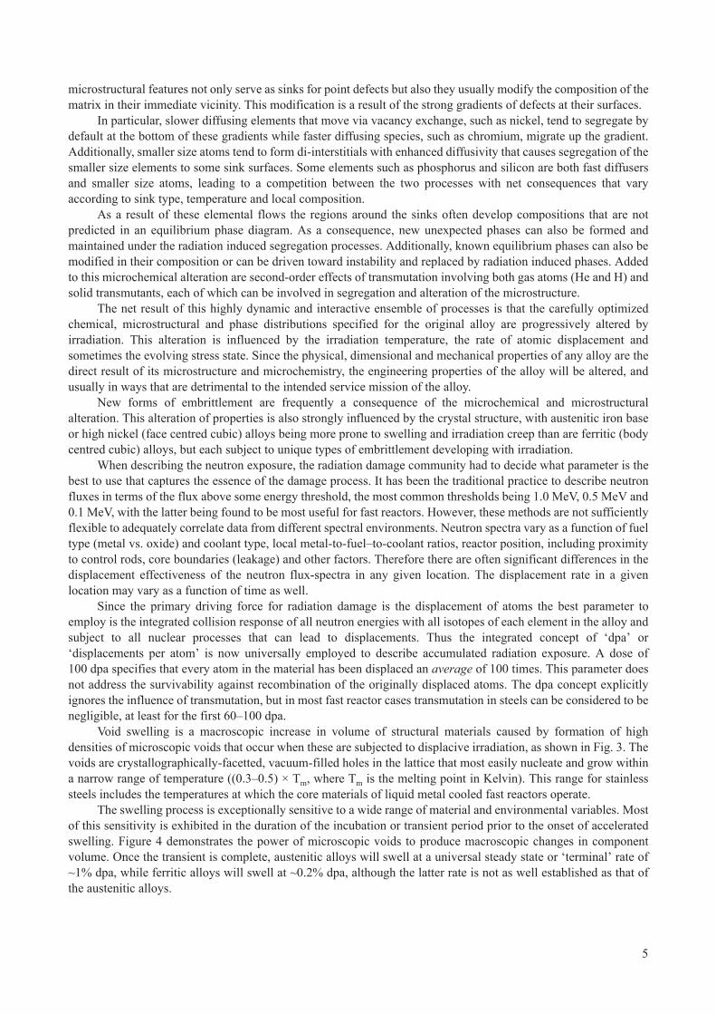
The swelling process is exceptionally sensitive to a wide range of material and environmental variables. Most of this sensitivity is exhibited in the duration of the incubation or transient period prior to the onset of accelerated swelling. Figure 4 demonstrates the power of microscopic voids to produce macroscopic changes in component volume. Once the transient is complete, austenitic alloys will swell at a universal steady state or ‘terminal’ rate of ~1% dpa, while ferritic alloys will swell at ~0.2% dpa, although the latter rate is not as well established as that of the austenitic alloys.
5

FIG. 2. Schematic representation of important phenomenon arising due to irradiation effects which determine the dimensional and mechanical stability of core components. Note that microchemical evolution and phase instability are not depicted in this figure.
FIG. 3. Voids observed in annealed Russian stainless steel EI-847 after 73 dpa at 335°C in the BN-350 fast reactor [4]. Volumetric swelling of ~6.2% has resulted from these voids.
6
Void swelling in the absence of physical restraints produces an isotropic distribution of mass and strains. When constrained, however, the distribution of mass shifts to unconstrained or lesser constrained directions. This redistribution of mass is accomplished as a result of the stresses generated by swelling against the constraint, activating the process of irradiation creep to drive mass away from the constraint. Figure 5 demonstrates the power of swelling and irradiation creep to distort fuel cladding in a fuel assembly.
Once void swelling approaches ~5%, however, it is not only the dimensional expansion that must be accommodated, but also the fact that the swelling then begins to dominate all aspects of the physical and mechanical properties as well as the behaviour and consequences of irradiation creep [3].
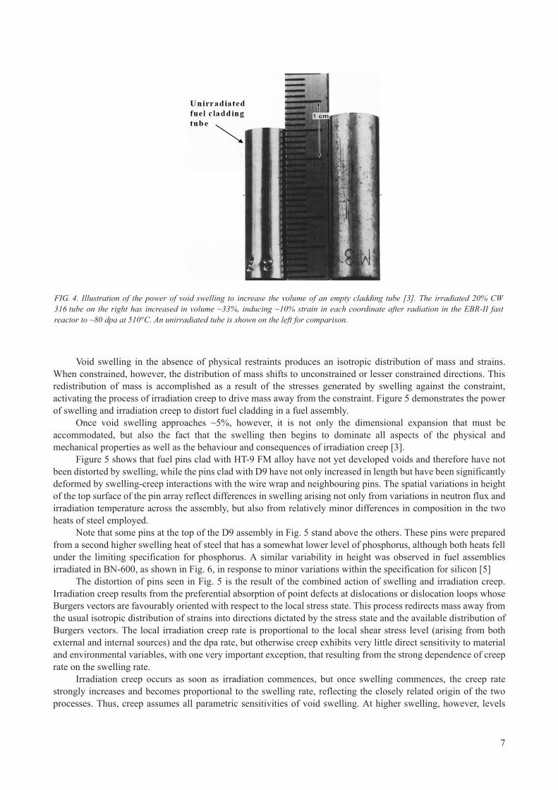
Figure 5 shows that fuel pins clad with HT-9 FM alloy have not yet developed voids and therefore have not been distorted by swelling, while the pins clad with D9 have not only increased in length but have been significantly deformed by swelling-creep interactions with the wire wrap and neighbouring pins. The spatial variations in height of the top surface of the pin array reflect differences in swelling arising not only from variations in neutron flux and irradiation temperature across the assembly, but also from relatively minor differences in composition in the two heats of steel employed.
Note that some pins at the top of the D9 assembly in Fig. 5 stand above the others. These pins were prepared from a second higher swelling heat of steel that has a somewhat lower level of phosphorus, although both heats fell under the limiting specification for phosphorus. A similar variability in height was observed in fuel assemblies irradiated in BN-600, as shown in Fig. 6, in response to minor variations within the specification for silicon [5]
The distortion of pins seen in Fig. 5 is the result of the combined action of swelling and irradiation creep. Irradiation creep results from the preferential absorption of point defects at dislocations or dislocation loops whose Burgers vectors are favourably oriented with respect to the local stress state. This process redirects mass away from the usual isotropic distribution of strains into directions dictated by the stress state and the available distribution of Burgers vectors. The local irradiation creep rate is proportional to the local shear stress level (arising from both external and internal sources) and the dpa rate, but otherwise creep exhibits very little direct sensitivity to material and environmental variables, with one very important exception, that resulting from the strong dependence of creep rate on the swelling rate.
Irradiation creep occurs as soon as irradiation commences, but once swelling commences, the creep rate strongly increases and becomes proportional to the swelling rate, reflecting the closely related origin of the two processes. Thus, creep assumes all parametric sensitivities of void swelling. At higher swelling, however, levels
FIG. 4. Illustration of the power of void swelling to increase the volume of an empty cladding tube [3]. The irradiated 20% CW 316 tube on the right has increased in volume ~33%, inducing ~10% strain in each coordinate after radiation in the EBR-II fast reactor to ~80 dpa at 510°C. An unirradiated tube is shown on the left for comparison.
7
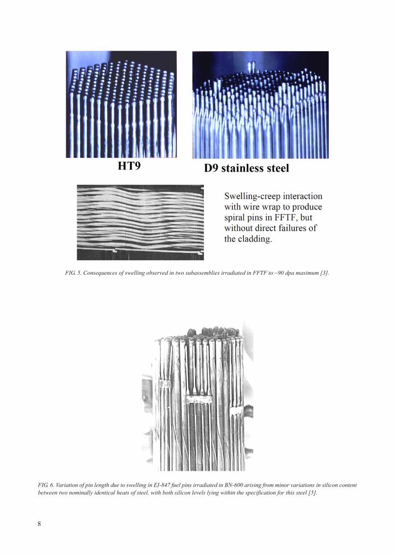
FIG. 5. Consequences of swelling observed in two subassemblies irradiated in FFTF to ~90 dpa maximum [3].
FIG. 6. Variation of pin length due to swelling in EI-847 fuel pins irradiated in BN-600 arising from minor variations in silicon content between two nominally identical heats of steel, with both silicon levels lying within the specification for this steel [5].
8

creep begins to ‘disappear’, however, such that as swelling increases the total dimensional strain (creep plus swelling) rate can never exceed 0.33% dpa, the level that represents one-third of the maximum or steady state swelling rate [6–7].
The creep coefficient for ferritic alloys in the absence of swelling has been measured to be about one-half that of austenitic steels, but once swelling commences the proportionality of creep to swelling is identical for both austenitic and ferritic alloys [8]. The disappearance of creep in FM alloys has not yet been observed, primarily because the swelling levels reached to date in these alloys are rather low.
Irradiation embrittlement is another consequence of radiation induced microstructural alteration [3, 9–11]. There are various mechanisms of embrittlement depending on the alloy of interest and its irradiation conditions. For austenitic alloys irradiation drives the microstructure toward an equilibrium distribution of various components that is strongly dependent on temperature and only weakly dependent on dpa rate. This equilibrium state is independent of the alloy’s starting state, so much so that the alloy forgets it starting condition after sufficient irradiation. Thus CW (hard) and annealed (soft) starting conditions converge to a common, often intermediate, hardness level that depends primarily on irradiation temperature. Below ~500°C the increased density of radiation induced microstructural components generally produces an increase in yield strength and a concomitant decrease in ductility. The residual ductility of fuel pin cladding is an important criterion that determines the life of a fuel pin. The loss of ductility is due to reduced capacity of the material to work harden, a process which leads to increased plastic instability.
At higher temperatures, other forms of embrittlement can occur. One form is helium embrittlement where transmutation induced helium atoms formed within the matrix migrate to grain boundaries and agglomerate to form helium bubbles at grain boundaries. Helium bubbles are believed to act as cavity nuclei and stress induced growth of these cavities occurs by vacancy diffusion along the boundary. Formation of cracks at the grain boundary occurs due to interlinking of the cavities at the grain boundary.
Another form of high temperature embrittlement is found in nickel base alloys. Since the source of most helium in alloys arises from the isotopes of nickel, more helium is formed in high nickel alloys, often agglomerating on grain boundaries. Additionally, these alloys derive their strength from formation of gamma prime and gamma-double prime phases in the matrix, but these phases are usually denuded at grain boundaries. Radiation induced development of these phases via nickel segregation occurs at the grain boundaries under some conditions, leading to very brittle boundaries.
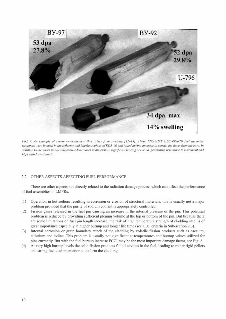
The AISI 300 series of alloys are especially prone to a late onset form of embrittlement that can produce extreme embrittlement during post-irradiation handling. When void swelling approaches ~10% (roughly independent of the irradiation temperature) a complex set of mechanisms involving stress concentration between voids, nickel segregation to void surfaces, reduction of the stacking fault energy of the matrix and alteration of the martensite start temperature, leads to a martensitic instability where the tearing modulus of the matrix plunges to zero. While under the sodium the temperature dependencies of the various processes usually precludes the development of extreme embrittlement, but once the component is removed from reactor the embrittlement is activated by the smallest of physical insults. Once swelling exceeds 15–20%, however, failure can occur under the sodium at temperature, especially if high withdrawal loads are required as a consequence of distortion induced by swelling and irradiation creep, leading to mechanical interference with neighbouring assemblies and support structures. An example of extreme embrittlement and its consequences is shown in Fig. 7.
Ferritic alloys are not particularly prone to the above cited forms of embrittlement, primarily because helium generation rates are low in alloys without significant amounts of nickel and swelling has not yet been observed at significant levels. However, another form of embrittlement predominates in ferritic alloys. It is well known that ferritic alloys are prone to failure at lower temperatures due to a ductile-brittle transition at some characteristic low temperature. The strongly increased density of radiation induced microstructural components often leads to an upward shift of the DBTT into the operating temperature range of the ferritic assembly. Additionally, some phases formed in ferritic and FM alloys during irradiation are rather brittle, requiring development of alloys that produce little or none of these phases.
9
2.2. OTHER ASPECTS AFFECTING FUEL PERFORMANCE
There are other aspects not directly related to the radiation damage process which can affect the performance of fuel assemblies in LMFRs.
(1) Operation in hot sodium resulting in corrosion or erosion of structural materials; this is usually not a major problem provided that the purity of sodium coolant is appropriately controlled.
(2) Fission gases released in the fuel pin causing an increase in the internal pressure of the pin. This potential problem is reduced by providing sufficient plenum volume at the top or bottom of the pin. But because there are some limitations on fuel pin length increase, the task of high temperature strength of cladding steel is of great importance especially at higher burnup and longer life time (see CDF criteria in Sub-section 2.3).
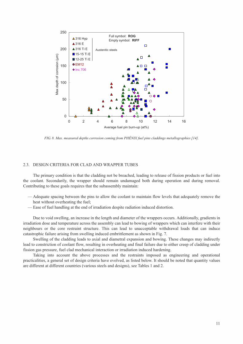
(3) Internal corrosion or grain boundary attack of the cladding by volatile fission products such as caesium, tellurium and iodine. This problem is usually not significant at temperatures and burnup values utilized for pins currently. But with the fuel burnup increase FCCI may be the most important damage factor, see Fig. 8.
(4) At very high burnup levels the solid fission products fill all cavities in the fuel, leading to rather rigid pellets and strong fuel clad interaction to deform the cladding.
FIG. 7. An example of severe embrittlement that arises from swelling [12–13]. These 12X18Н9T (18Cr-9Ni-Ti) fuel assembly wrappers were located in the reflector and blanket regions of BOR-60 and failed during attempts to extract the ducts from the core. In addition to increases in swelling-induced increases in dimension, significant bowing occurred, generating resistance to movement and high withdrawal loads.
10
2.3. DESIGN CRITERIA FOR CLAD AND WRAPPER TUBES
The primary condition is that the cladding not be breached, leading to release of fission products or fuel into the coolant. Secondarily, the wrapper should remain undamaged both during operation and during removal. Contributing to these goals requires that the subassembly maintain:
— Adequate spacing between the pins to allow the coolant to maintain flow levels that adequately remove the heat without overheating the fuel;
— Ease of fuel handling at the end of irradiation despite radiation induced distortion.
Due to void swelling, an increase in the length and diameter of the wrappers occurs. Additionally, gradients in irradiation dose and temperature across the assembly can lead to bowing of wrappers which can interfere with their neighbours or the core restraint structure. This can lead to unacceptable withdrawal loads that can induce catastrophic failure arising from swelling induced embrittlement as shown in Fig. 7.
Swelling of the cladding leads to axial and diametral expansion and bowing. These changes may indirectly lead to constriction of coolant flow, resulting in overheating and final failure due to either creep of cladding under fission gas pressure, fuel clad mechanical interaction or irradiation induced hardening.
Taking into account the above processes and the restraints imposed as engineering and operational practicalities, a general set of design criteria have evolved, as listed below. It should be noted that quantity values are different at different countries (various steels and designs), see Tables 1 and 2.
0
50
100
150
200
250
0 2 4 6 8 10 12 14 16Average fuel pin burn-up (at%)
Max
dep
th o
f cor
rosi
on (μ
m)
316 Hyp316 E316 Ti E15-15 Ti E12-25 Ti EEM12Inc 706
Full symbol: ROGEmpty symbol: RIFF
Austenitic steels
FIG. 8. Max. measured depths corrosion coming from PHÉNIX fuel pins claddings metallographies [14].
11

3. SELECTION OF CLAD AND STRUCTURAL MATERIALSFOR LMFRs
3.1. FUEL SUBASSEMBLIES USED IN FAST REACTORS
Fuel subassemblies for the fast reactors SUPERPHÉNIX-1, PFBR, BN-600 and FBTR are shown in Figs 9–12. Clad tubes and wrappers are the critical structural materials for the fuel assemblies. Materials used in sodium cooled fast neutron reactors (SFRs) are given in Table 3 and their chemical composition in Table 4.
3.2. EARLY HISTORY OF STRUCTURAL MATERIALS FOR LMFRs
Swelling is sensitive to a number of operational variables with the irradiation temperature ranking as the highest in importance, followed by the dpa rate and then the stress level. The first generation of fast reactors (e.g. EBR-I, DFR) had relatively low inlet coolant temperatures on the order of 270–280°C. Although at BR-5 (later BR-10) reactor the inlet temperature was 375°C, but the irradiation dose was low at the first core loading (1959–1964). This tended to minimize the then-unknown phenomenon of swelling. When swelling at relatively low
TABLE 1. CLADDING DESIGN CRITERIA
Cladding [15–18]
1. Hot spot mid-wall temperature (steady state conditions) <700C
2. Hot spot mid-wall temperature (transient conditions) <800C
3. Primary + secondary stress level <Yield point
4. Diametral increase: In view point of maintenance of geometry to allow cooling. <7%In view point of allowable cladding embrittlement due to swelling. <3%
5. Thermal creep strain <0.2%
6. Cumulative creep-rupture damage factor (CDF)— for normal op. conditions; <0.2–0.3— with account of other events, storage and spent fuel handling. <1
TABLE 2. WRAPPER DESIGN CRITERIA
Wrapper [19]
The wrapper design criteria depends on the type of the core restraint system: passive (BN reactors in Russia, FFTF, Joyo, Monju, SNR), natural (EBR-II, Rapsodie, Phénix, SPX) and leaning post concept (PFR). In general, three limiting wrapper mechanisms are bowing, length change and dilation, but their values are different for different core designs.
The limit of wrapper length change and bowing depend on the capability of fuel handling machine and in-reactor storage system, and also on the influence on the reactivity; the restriction of wrapper dilation (flat-to-flat size increase) is connected with possibility to fuel reloading with wrapper integrity keeping.
1. Bowing at top 10–17 mm
2. Maximum free bowing 8.5–30 mm
3. Maximum increase in width across flats Gap value between FAs
4. Primary + secondary stress level <Yield point
12

levels was discovered in DFR [20], there was a rush to look for swelling in other reactors. EBR-II was a second generation reactor with an inlet temperature of 370°C and double-digit levels of swelling were quickly found in the relatively swelling prone steel AISI 304. These first studies focused on the easily retrievable ducts that enclosed control rod and safety rods. These ducts operated at relatively low temperatures compared to fuel pins, however.
The initial design of the EBR II and its operation started in 1964 and did not anticipate the swelling and irradiation creep phenomena. Swelling was not discovered until 1967 [20] and the phenomenon of irradiation creep in austenitic steels till 1969 [21]. Several other second generation LMFRs were in the design stage during this period; hence the late discovery of these phenomena caused no serious problem. In EBR-II, however, discovery of creep and swelling required major changes in both fuel assembly design and steels. In BN-600 the core project parameters were corrected just before the reactor commissioning: maximum burnup value decreased from 10–7 at.% after the new data on wrapper steel (16Cr-11Ni-3Mo) swelling had been received from the BN-350.
The full evolution of structural materials is difficult to cover in a publication such as this one, but since swelling and creep were first observed at large levels in EBR-II, it is instructive to start with the first major publication that focused on design and material changes, as well as changes in operation required for a given fuel assembly.
TABLE 3. MATERIALS USED FOR CLAD AND WRAPPER IN LMFRs
Reactor Country Clad material Wrapper material
CEFR China ChS-68CW EP-450
EFR Europe ALM1 or PE16 EM10 or Euralloy
Rapsodie France 316
PHÉNIX France 15-15 Ti EM10
SUPERPHÉNIX France 15-15 Ti EM10
KNK-II Germany 1.4970 1.4981
FBTR India 316 (CW) 316 L (CW)
PFBR India 20% CW D9 D91
JOYO Japan 316 (20% CW) 316 (20% CW)
MONJU Japan PNC 316 (20% CW) PNC 316 (20% CW)
JSFR Japan ODS PNC-FMS
BN-350 Kazakhstan EI-847 ChS-68CW (from 1987)
16Cr-11Ni-3MoEP-450 (from 1987)
KALIMER Republic of Korea HT9 HT9
BR-10 Russian Federation EI-847 18Cr-9Ni-Ti
BOR-60 Russian Federation ChS-68CW EP-450
BN-600 Russian Federation ChS-68CW (from 1987) EP-450 (from 1987)
BN-800 Russian Federation ChS-68CW-I stageEK-181-II stage
EP-450
BN-1200 Russian Federation EK-164CW-I stage EK-181-II stageODS-III stage
EP-450
DFR UK Niobium —
PFR UK STA Nimonic PE 16 PE16/ FV448
EBR-II USA 316 —
Fermi USA Zr —
FFTF USA 316 (20% CW), HT9 316 (20% CW) , HT9
13

FIG. 9. Subassembly for BN 600.
14

FIG. 10. Subassembly for PFBR.
15

An analysis of the effects of the swelling and irradiation creep phenomena in EBR-II driver assemblies was reported in 1979. A summary of the changes made was documented by Walters and Walter [22]. The changes made in the initial Mark 1A to produce the Mark II driver fuel assemblies are summarized in Table 5. The purpose of the changes was to increase the enrichment and to accommodate the various consequences of increased enrichment, as well as the impact of irradiation creep and swelling on the fuel pin design.
In the initial Mark 1A, the fission gases were largely retained in the fuel while the Mark II design allowed fuel expansion to take place and fission gas release to be more effective.
The ducts of the original fuel assemblies were made of AISI 304 stainless steel and were not heat-treated after forming. The corners of the duct had a retained cold work of 15% which tended to reduce the swelling in the corners compared to that in the flats. These ducts had mid-plane temperatures in the range of 400–415C and were subject to pressure differences of 28–123 KPa. Fuel handling difficulties might have resulted arising from differential swelling and creep to produce bowing in addition to swelling-induced dilation.
Surprisingly, the driver fuel sub-assemblies in EBR-II never bowed more than 1 mm even up to 8% burnup due to following reasons:
— Neighbouring subassemblies provided restraint such that opposing stresses was developed. Such stresses were relaxed by irradiation creep producing a reverse bowing that tended to cancel the effect of differential swelling;
FIG. 11. Subassembly for SUPERPHÉNIX-1.
16
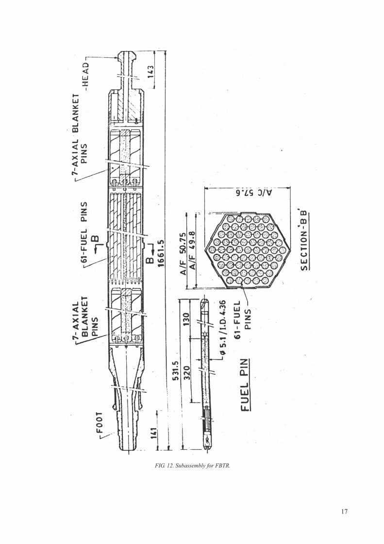
FIG. 12. Subassembly for FBTR.
17

TAB
LE
4. T
YP
ICA
L C
OM
PO
SIT
ION
(IN
WT
%)
OF
CO
RE
ST
RU
CT
UR
AL
MA
TE
RIA
LS
IN
LM
FR
s
AL
LO
YC
Cr
Ni
Mo
Si
Mn
VN
bT
iP
SN
BO
ther
s
Au
sten
itic
sta
inle
ss s
teel
s
304
SS
0.05
1810
0.3
0.4
1.5
——
——
——
——
316
SS
0.05
1713
20.
61.
8—
——
——
—0.
002
—
Jap
an
PNC
316
0.05
516
.014
.02.
500.
801.
80—
0.08
0.10
0.02
8—
——
—
PNC
152
00.
0615
.020
.02.
500.
801.
90—
0.11
0.25
0.02
5—
——
—
Fra
nce
316T
i0.
0516
142.
50.
61.
7—
—0.
40.
03—
——
—
15-1
5Ti
0.1
1515
1.2
0.6
1.5
——
0.4
0.00
7—
—0.
005
—
15-1
5Ti o
pt0.
115
151.
20.
81.
5—
—0.
40.
03—
—0.
005
—
15-1
5Ti m
od0.
085
14.9
14.8
1.46
0.95
1.50
——
0.50
0.00
7—
—0.
004
—
US
A
D9
0.05
213
.815
.21.
500.
921.
74—
—0.
230.
003
——
——
D9I
***
13.5
15.5
1.8–
2.22
0.8
2.0
——
0.25
0.02
5–0.
040.
005–
0.01
0.00
50.
004–
0.00
6—
AST
M A
771
0.03
–0.0
512
.5–1
4.5
14.5
–16.
51.
5–2.
50.
5–1.
01.
65–2
.35
—0.
05 m
ax.
0.1–
0.4*
0.04
max
.0.
01 m
ax.
——
—
Ind
ia
D9
(PF
BR
)0.
035–
0.05
013
.5–1
4.5
14.5
–15.
52.
0–2.
50.
50–0
.75
1.65
–2.3
5—
0.05
max
.5.
0C–7
.5C
0.02
max
.0.
01 m
ax.
——
—
D9I
0.04
–0.0
5**
13.5
–14.
514
.5–1
5.5
2.0–
2.5
0.7–
0.9
1.65
–2.3
5—
0.05
max
.0.
250.
025–
0.04
——
0.00
4–0.
006
—
Ger
man
y
1.49
700.
115
151.
20.
41.
5—
—0.
5—
——
0.00
5—
UK
FV54
80.
0916
.511
.51.
40.
31
—0.
7—
——
——
—
Ru
ssia
n F
eder
atio
n
EI-
847
0.04
–0.0
615
–16
15–1
62.
7–3.
2<
0.4
0.4–
0.8
<0.
9<
0.02
ChS
-68
0.05
–0.0
815
.5–1
714
.0–1
5.5
1.9–
2.5
0.3–
0.6
1.3–
20.
1–0.
3—
0.2–
0.5
<0.
02—
—0.
002–
0.0
05—
EK
-164
0.05
–0.0
915
–16.
518
–19.
52–
2.5
0.3–
0.6
1.5–
20.
150.
1–0.
40.
25–0
.45
0.01
–0.0
30.
001–
0.00
50.
15C
e
Nic
kel-
base
all
oys
PE16
0.13
16.5
43.5
3.3
0.2
0.1
——
1.3
——
——
1.3
(Al)
INC
706
0.01
1640
0.02
0.09
0.4
—3
1.5
——
——
—
12R
N72
HV
0.1
1925
1.4
0.4
1.8
——
0.5
——
—0.
0065
—
18

Fer
riti
c-m
arte
nsit
ic a
lloy
s
UK
FI0.
1513
.00.
47—
0.30
0.45
——
——
——
——
FV60
70.
1311
.10.
590.
930.
530.
800.
27—
——
——
——
CR
M-1
20.
1911
.80.
420.
960.
450.
540.
30—
——
——
——
FV44
80.
1010
.70.
640.
640.
380.
860.
160.
30—
——
——
—
Fra
nce
F17
0.05
17.0
0.10
—0.
300.
40—
——
0.0
080
.008
0.02
0—
—
EM
100.
109.
00.
201.
00.
300.
50—
——
0.0
08—
——
—
EM
120.
109.
00.
302.
00.
401.
000.
400.
50—
0.0
080
.008
——
—
T91
0.10
9.0
<0.
400.
950.
350.
450.
220.
08—
0.0
080
.008
0.05
0—
—
Ger
man
y
1.49
230.
2111
.20.
420.
830.
370.
500.
21—
——
——
——
1.49
140.
1411
.30.
700.
500.
450.
350.
300.
25—
——
0.02
90.
007
—
1.49
14 m
od0.
16–0
.18
10.2
–10.
70.
75–0
.95
0.45
–0.6
50.
25–0
.35
0.60
–0.8
00.
20–0
.30
0.10
–0.2
5—
——
0.01
0 m
ax.
0.00
15 m
ax.
—
US
A
HT
90.
2011
.90.
620.
910.
380.
590.
30—
——
——
—0.
52 (
W)
403
0.12
12.0
0.15
—0.
350.
48—
——
——
——
—
Jap
an
PNC
-FM
S 0
.211
0.4
0.5
——
0.2
0.05
——
—0.
05—
—
Ru
ssia
n F
eder
atio
n
EP
-450
0.1–
015
12–1
4<
0.3
1.2–
1.8
<0.
6<
0.6
0.1–
0.3
0.25
–0.5
5—
——
—0.
004
—
EK
-181
0.1–
0.2
10–1
2<
0.1
<0.
010.
3–0.
50.
5–0.
80.
2–1
<0.
010.
003–
0.3
0.00
3–0.
006
(1–2
)W(0
.05–
0.3)
Ta
ChS
139
0.18
–0.2
11–1
2.5
0.5–
0.8
0.4–
0.6
0.2–
0.3
0.5–
0.8
0.2–
0.3
0.2–
0.3
0.00
3–0.
30.
003–
0.00
6(1
–1.5
)W
Not
e:
Fe
bala
nce
( ***) a
djus
ted
such
that
Ti/
(C+
N)
= 5
, ( **) a
djus
ted
such
that
Ti/
C =
4–5
, ( *) targ
et T
i =0.
25%
.
TAB
LE
4. T
YP
ICA
L C
OM
PO
SIT
ION
(IN
WT
%)
OF
CO
RE
ST
RU
CT
UR
AL
MA
TE
RIA
LS
IN
LM
FR
s (c
ont.)
AL
LO
YC
Cr
Ni
Mo
Si
Mn
VN
bT
iP
SN
BO
ther
s
19

— Regular changes in location of sub-assemblies, including their rotation, the latter tending to reverse the effects of flux gradients across an assembly.
In addition to bowing of the duct faces, dilation of the duct occurred from creep and swelling. This distortion did not cause any difficulty in the fuel handling because close monitoring was maintained during reactor operation. Dilation was maintained below 1 mm, which is the limiting requirement. Inner ducts were subjected to higher deformation than the outer ducts.
It was a possibility that changes in fuel cladding dimensions can lead to flow blockage in the assembly. To forestall this possibility, the initial design alloy 304L was changed to 316 in Mark II fuel assemblies since recent studies had shown lower swelling in 316 in side by side comparisons of the two alloys [23].
Other observations relevant to fuel failure or ‘breaching’ were as follows:
— Mark 1A experienced higher cladding and fuel mechanical interaction. In the Mark II design, low creep strains and high burnup to breach were experienced due to minimal fuel and cladding mechanical interaction;
— The length changes of the pins followed the trends seen in the diameter changes, a direct consequence of isotropic swelling;
— All breaches in Mark 1A (304L) and Mark II (316) were intergranular in nature.
The foregoing discussion foreshadowed many issues to be addressed in later alloy development efforts. Specifically, this study indicated that the role of cold working and other thermal-mechanical processing conditions, as well as the role of composition, would be very important.
3.3. AUSTENITIC STAINLESS STEELS AND THEIR RESPONSE TO IRRADIATION IN LMFRs
Engineering consequences of irradiation induced changes, such as void swelling, irradiation creep and embrittlement, are very important as these affect the residence time of core components in the reactor and hence determine the achievable burnup and the consequent economic viability of LMFRs. Type 316 stainless steel or near-equivalent steels were employed most extensively in early cores of LMFRs since it was observed that the use of 316 tended to delay the onset of swelling compared to the behaviour observed in AISI 304.
It was realized rather early that the primary determinant of the swelling difference was the higher nickel level of AISI 316 relative to that of 304. This dependence of increasing swelling resistance with higher nickel was shown in ion bombardment simulation studies to be applicable to a wide range of alloys and nickel levels [24], but it was not clear from these studies if the swelling rate and/or the transient regime of swelling were affected by the nickel level. The ion studies also indicated that beyond 35–40% nickel the swelling again increased with increasing nickel
TABLE 5. COMPARISON OF MARK1A AND MARK II DRIVER FUEL FOR EBR-II
Feature Mark 1A Mark II
Enrichment (at.% U235) 52.5 67.0
Fuel pin length, mm 343 343
Fuel pin diameter, mm 3.65 3.30
Fuel volume, m3 3.6 × 10⁻⁶ 2.9 × 10⁻⁶
Fuel cladding radial gap, mm 0.152 0.254
Cladding wall thickness, mm 0.229 0.305
Cladding OD, mm 4.42 4.42
Cladding material Type 304L (annealed) Type 316 (annealed)
Element length, mm 460 612
Plenum volume, m3 0.67 × 10⁻⁶ 2.41 × 10⁻⁶
20

content. The first reported comprehensive comparisons of neutron induced swelling in both model and commercial alloys exhibited the same influence of nickel content [25].
Garner and co-workers later showed that the effect of nickel content was manifested only in the transient regime of swelling and that the minimum swelling could occur over a wide range of nickel contents (30–50%) depending on both environmental and compositional variations in elements other than nickel [26–28].
Figure 13 (a) and (b), shows the influence of nickel content on void swelling at different temperatures for simple ternary alloys in the annealed condition subjected to irradiation in EBR-II. While the dependence on nickel at a given dose is strong, the primary role of nickel is to determine the duration of the transient regime of swelling prior to the onset of steady state swelling at ~1% dpa. The swelling is usually observed to be non-monotonic with
FIG. 13. (a) Influence of temperature, neutron fluence and nickel content on swelling at a given dose for annealed ternary Fe-15Cr-Ni alloys irradiated in EBR II [28]. (b) Influence of temperature and nickel content on swelling vs. dose for annealed ternary Fe-15Cr-Ni alloys irradiated in EBR II [29].
21

nickel level. Between 10–40% nickel, the transient regime of swelling in these simple alloys is progressively increased, leading to a reduction in swelling at a given neutron fluence or dpa level. However, the influence of chromium was found to be monotonic, with increasing chromium causing shorter transients and therefore higher swelling at all nickel levels. Decreases in chromium to reduce swelling are restricted due to the necessity to provide sufficient corrosion resistance. Similar swelling trends with nickel and chromium were observed in solute-bearing alloys of increasing complexity [29].
Garner and co-workers also showed that the major influence of solute addition was manifested only in the transient duration. As the insight grew concerning the effect of both major and minor elements on swelling, however, the major focus was on the use of 316 stainless as a lower-swelling replacement for 304 stainless. Unacceptably high levels of void swelling at doses beyond ~50 dpa were observed to occur in annealed AISI 316 in the temperature range characteristic of fast reactors and the swelling was unaccountably highly variable from heat to heat [30]. It took some years to determine that most of the variability arose from relatively minor variations in minor elements and especially in the thermal-mechanical treatments that determined the distribution and chemical activities of these minor elements [3, 31].
Since there are various reasons that preclude the use of significantly higher nickel levels to achieve lower swelling (cost of nickel, higher levels of parasitic neutron capture, greater tendency to radiation induced phase instability, higher helium generation) the approach used initially in all national programmes was to make various modifications in the composition of AISI 316 stainless steel with modifications in chemical composition in elements other than nickel.
As shown in Fig. 14, it was shown in many early studies that cold-working to levels of 15–30% significantly delayed swelling [3, 32–33], so most compositional modifications also involved the use of CW material. Figure 15 shows the typical improvement in resistance to void swelling with modifications in chemical composition of CW alloys.
Before proceeding with a discussion of compositional modifications to reduce swelling while not sacrificing other attributes such as ductility, it is useful to consider the nature of the swelling process. Generally, voids form in austenitic stainless steels in the temperature range of 573–973 K with the void nucleation process often accelerated by helium produced by (n, ) reactions [35]. The formation and growth of voids are sensitive to nearly all metallurgical variables like chemical composition, fine details of thermo-mechanical history and irradiation parameters like fluence, dose rate, irradiation temperature, stress state and often time-varying histories of irradiation variables, especially in temperature history. The fluence dependence of swelling can be described as a low swelling rate (often zero) transient period followed by acceleration to a regime of linear or near-linear swelling rate of ~1% dpa, often called‘steady state swelling’ as shown in Fig. 16. The majority of the parametric sensitivities of swelling have been found to express themselves only in the duration of transient regime. The transition to the steady state regime appears to depend on several factors.
The first factor is the requirement of development of a ‘glissile’ dislocation network of intermediate density (~1010 cm–2). A ‘sessile’ loop-dominated microstructure will allow void nucleation at reduced levels but does not support the development of a high swelling rate. In simple solute-free austenitic alloys irradiated in the annealed state the transition to steady state swelling is related to the unfaulting of the sessile radiation-produced dislocation loop microstructure and subsequent development of a glissile dislocation network [3]. In CW metals the dislocation network already exists but at densities too high to allow void nucleation. In this case the network must relax to the same density as will be reached by the annealed metal before the high swelling regime can begin.
In solute-free simple Fe-Cr-Ni ternaries this sessile-to-glissle transformation is facilitated if the loop ensemble is composed of a relatively low density of large loops that is relatively easy to unfault. As shown in Fig. 17 it has been shown by Okita and co-workers that as the dpa rate is progressively reduced the transient regime is also reduced, approaching zero under some conditions [36]. Okita and co-workers showed that decreasing dpa rates led to more easily unfaultable loop microstructures. Garner and co-workers showed that under some conditions that do not favour void nucleation in simple Fe-Cr-Ni ternaries that CW material swelled sooner than annealed material, since relaxing the high density of cold-work dislocations was faster than nucleation and unfaulting of Frank loops [3, 37].
In more complex solute-containing alloys, void nucleation is suppressed by the addition of highly diffusive elements such as silicon and phosphorous. Both nickel increases and P, Si additions increase the effective vacancy mobility, in effect raising the homologous temperature of the alloy and reducing the supersaturation of vacancies that drives void nucleation [28, 38–39]. While nickel increases the effective vacancy diffusion, chromium additions
22

FIG. 14. Effect of cold-working on 316 (top) and 304 stainless steels (bottom) [32–33].
FIG. 15. Improvement in void swelling resistance arising from modifications in chemical composition of near-316 alloys [34].
23

decrease it, leading generally to a shorter transient and therefore an increase in swelling. On a per atom basis the strongest reduction in swelling arises from P, then Si and finally Ni [28]. The action of these three elements to reduce swelling has been demonstrated to exert their effect while in solution, with no precipitation involved [3].
However, under irradiation the various radiation induced segregation processes tend to concentrate these three elements into precipitates, removing them from solution and returning the alloy matrix to a homologously ‘cooler’ and therefore higher nucleating state. The mechanisms producing this reduction in matrix solute levels have been characterized as ‘microchemical evolution’ or phase decomposition. In the absence of other solutes the phase formed is usually the non-equilibrium gamma-prime phase Ni3Si. When solutes such as carbon and carbide-forming elements (Ti, Zr, Nb, Hf) and intermetallic-forming elements such as Mo are added, the range and complexity of precipitates is vastly increased. Equilibrium, near-equilibrium and non-equilibrium phases are all subjected to the radiation-driven segregation processes that compete to remove Ni, P and Si from solution in the
FIG. 16. Schematic representation of different regimes of swelling vs. dose.
FIG. 17. Strong effect of dpa rate on the swelling of simple ternary and quaternary alloys in FFTF. Note that no precipitation occurred in these alloys before or during irradiation [36].
24

matrix. Some phases are initially more stable than others but yield later to other phases as the consequences of segregation feed back into the matrix composition.
This complexity of microchemical evolution and its dependence on both material and environmental variables opens the door to alloy modification to resist the formation of phases rich in Ni, Si and P, thereby delaying the onset of high swelling rates. For most commercial austenitic alloys the microchemical evolution is the dominant factor that determines the duration of the transient regime. There is no one single path in compositional space to effectively prolong the transient regime of swelling, but most national programmes have converged to slightly higher levels of nickel, silicon and phosphorous balanced with various levels of carbide-forming elements. Of special importance is a correct balance of carbon and carbide-forming elements, especially titanium. Elements like nitrogen and especially boron are known to affect the activity of carbon and its rate and path of precipitation [3].
3.4. PRECIPITATION CONTROL BASIS FOR COMPOSITIONAL MODIFICATIONIN AUSTENITIC STEELS
As shown in Table 6, there are three classes of phases that can participate in the microchemical evolution.The first class of phases includes radiation-enhanced or radiation-retarded thermally stable phases. In this
group, precipitate phases that form during thermal aging are either produced more rapidly, more abundantly or often at lower temperatures or that are produced less abundantly and at higher temperatures during reactor irradiation. These phases have almost the same composition whether produced during thermal aging or during reactor irradiation. Phases in this category include M6C, M23C6 and MC carbides and and intermetallics.
The second class of phases contains radiation-modified thermal phases where the irradiation-produced composition is different from the composition produced during thermal aging. Phases in this category include M6C, Laves and FeTiP.
The third class of phases contains the radiation induced phases. These phases are uniquely produced by reactor irradiation and include Ni3Si('), G-phase (M6Ni16Si7) silicides and needle-shaped MP, M3P or M2P phosphides.
Formation of high densities of small precipitates such as phosphides and TiC are also thought to enhance recombination of point defects and thereby delay the onset of void swelling. Additionally, fine precipitates are also thought to delay the onset of swelling by providing high sink densities for helium, reducing helium locally to subcritical levels so that nucleation of voids is delayed [42]. The influence of such mechanisms is eventually overwhelmed by continued radiation induced segregation, however, eventually causing dissolution of phosphides and TiC, concurrent with precipitation of phases rich in nickel and silicon, with consequent acceleration of void nucleation and growth. It has been demonstrated many times that incubation period for swelling is prolonged by extending the duration of the neutron exposure required to cause phosphide dissolution. Titanium additions have been shown to lead to the maintenance of more stable phosphides.
The addition of Ti has been found to be very effective in reducing void swelling. Titanium-stabilized austenitic steels (316Ti and 15-15Ti) have therefore been chosen as reference structural materials of the fuel subassemblies of French fast breeder reactors, PHÉNIX and SUPERPHÉNIX. Titanium is also an important alloying addition in alloy D9 developed in USA. These titanium-modified steels are always used in the CW condition.
In Fig. 15, one can compare the performance of several clad materials which clearly shows the gain achieved when moving from unstabilized 316 to 316Ti, 15-15Ti and a silicon-modified version of 15-15Ti steel. The major difference in these four alloys shown in Fig. 15 is due to large differences in the incubation dose for swelling. Even
TABLE 6. CLASSES OF PRECIPITATE PHASES OBSERVED TO FORM IN 300 SERIES AUSTENITIC STAINLESS STEELS DURING IRRADIATION [40–41]
Radiation enhanced/ retarded phases Radiation-modified phases Radiation induced phases
M6C, Laves, M23C6, MC, ,
M6C, Laves, M2P M6Ni16Si7 (G), Ni3Si (g ¢), MP, M2P, M3P
25

in the absence of carbon the presence of titanium in solution inhibits void swelling as demonstrated in Fe-15Cr-16Ni model alloys where an addition of 0.25 wt% Ti was found to decrease cavity density significantly at higher temperatures [43]. When carbon was also present, there was further reduction in cavity density particularly at higher temperatures, attributed to the presence of fine MC carbides.
The Ti/C ratio has been shown to play an important role in determining irradiation behaviour of austenitic steels DIN 1.4970. Maximum swelling resistance has been obtained when the Ti/C ratio is below the stoichiometric composition; i.e. when the material is understabilized [44]. The reason for this behaviour is the synergistic interrelation between freely migrating carbon and the formation of finely dispersed TiC particles. Carbon, in the absence of titanium, is captured in large M23C6 precipitates and is not available for vacancy trapping. Fine TiC particles are continually dissolved by recoil dissolution and thereby contribute to trapping so long as the steel is understabilized; i.e. for a Ti content of less than four times the carbon content in weight percentage. Figure 18 demonstrates the impact of the Ti/C ratio.
The role of niobium is similar to the influence of titanium where the presence of fine NbC precipitates confers void swelling resistance to austenitic steels, particularly in the temperature range of their precipitation.
The influence of phosphorous addition is more pronounced when other solutes, such as Ti, Si, and Nb are also present. Figures 19 and 20 show the variation of swelling with dose for 316Ti and 316TiP steels [44, 46]. It is seen that the addition of phosphorous increases the swelling resistance of CW titanium stabilized 316 steel, particularly when combined with the addition of carbide-forming elements. Figure 19 also highlights the role of applied stress to accelerate the onset of void swelling.
FIG. 18. Suppression of void swelling by Ti addition in 20% CW 316SS as demonstrated both by neutron and ion irradiation [45].
FIG. 19. Effect of hoop stress and phosphorus addition on the swelling of two titanium-modified 316 stainless steels, irradiated in the form of pressurized tubes in PHÉNIX [46].
26

The effects of radiation variables such as temperature, stress and dpa rate on void swelling are expressed not only in the evolution of the dislocation microstructure but can express themselves in effects on development of precipitate microstructure. While shear stresses accelerate the unfaulting of Frank loops and the development of a glissile network, tensile stresses favour development of phases which contribute to dilation of the lattice. Intermetallic phases often lead to an apparent swelling of 2–3%. Intermetallic phases are rather sensitive to time rather than dpa rate but lower dpa rates require longer time to reach a given dpa level, thereby enhancing the probability of their formation [46].
Radiation induced phases such as gamma-prime and G-phase are strongly accelerated by increasing dpa rates. Radiation modified phases are also sensitive in their composition and their rate of development to the dpa rate. In more complex commercial alloys it is likely that both the effect of dpa rate on dislocation evolution and on precipitate evolution is involved to affect the duration of the transient regime of swelling.
As an example, a study on a variety of austenitic stainless steels was conducted showing that void swelling appears to be increased when the dpa rate is decreased in variants of Fe–16Cr–15Ni–3Mo austenitic stainless steel irradiated in BN-350 and BOR-60 [47]. The swelling behaviour of these steels is shown in Fig. 21. In each reactor, the specimens experienced similar temperature and dpa levels, but the irradiation proceeded at 5.06 × 10⁻⁷ dpa·s–1
in BOR-60 and 1.58 × 10⁻⁶ dpa·s–1 in BN-350, approximately a factor of three in rate. The fluences attained were nearly identical at 11.5 × 10²² n·cm–2 and 11.9 × 10²² n·cm–2 (E > 0.1 MeV), respectively. In all six steels, a significantly higher swelling level was attained in BOR-60, agreeing with the results that void swelling appears to be increased when the dpa rate is decreased.
3.5. FERRITIC AND FM ALLOYS AND THEIR RESPONSE TO IRRADIATION IN LMFRs
While the study of austenitic alloys has received a very large amount of experimental attention, much less attention has been devoted to ferritic and FM alloys, primarily because they became of intensified interest as a result of the failure of high-swelling austenitics to reach the 200–250 dpa needed for maximum fuel burnup. Thus the known deficiencies of ferritic alloys have been partially overlooked in favour of their known lower swelling behaviour. The first major conference to address the possibility of using this class of alloys was held in 1983, a decade after the intense focus on austenitics was initiated [48].
Experimental programmes continue first to develop and optimize conventional alloys in this category and then develop new dispersion-strengthened alloys that offer the strength required at higher temperatures. Unfortunately the number of fast reactors available to conduct new high dose irradiations has declined as reactors have been decommissioned, thereby limiting the rate at which such testing can be conducted.
FIG. 20. Effect of the phosphorous level on the swelling behaviour of 20% CW 316 stainless steel [45].
27
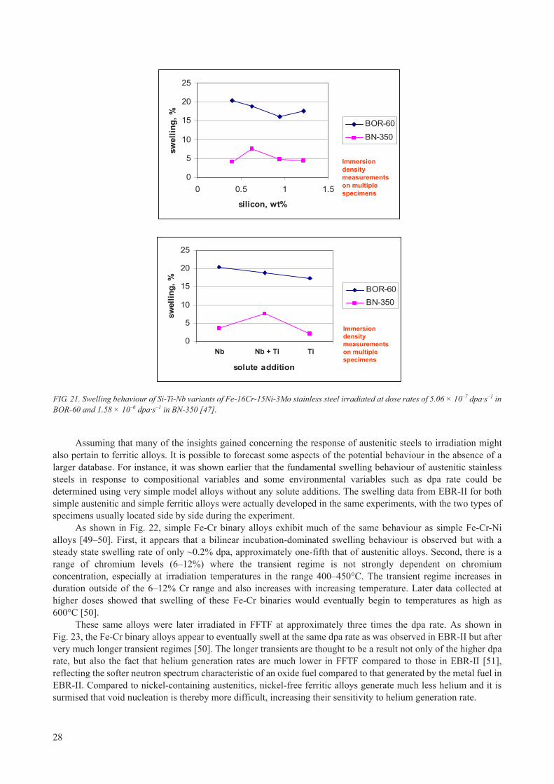
Assuming that many of the insights gained concerning the response of austenitic steels to irradiation might also pertain to ferritic alloys. It is possible to forecast some aspects of the potential behaviour in the absence of a larger database. For instance, it was shown earlier that the fundamental swelling behaviour of austenitic stainless steels in response to compositional variables and some environmental variables such as dpa rate could be determined using very simple model alloys without any solute additions. The swelling data from EBR-II for both simple austenitic and simple ferritic alloys were actually developed in the same experiments, with the two types of specimens usually located side by side during the experiment.
As shown in Fig. 22, simple Fe-Cr binary alloys exhibit much of the same behaviour as simple Fe-Cr-Ni alloys [49–50]. First, it appears that a bilinear incubation-dominated swelling behaviour is observed but with a steady state swelling rate of only ~0.2% dpa, approximately one-fifth that of austenitic alloys. Second, there is a range of chromium levels (6–12%) where the transient regime is not strongly dependent on chromium concentration, especially at irradiation temperatures in the range 400–450°C. The transient regime increases in duration outside of the 6–12% Cr range and also increases with increasing temperature. Later data collected at higher doses showed that swelling of these Fe-Cr binaries would eventually begin to temperatures as high as 600°C [50].
These same alloys were later irradiated in FFTF at approximately three times the dpa rate. As shown in Fig. 23, the Fe-Cr binary alloys appear to eventually swell at the same dpa rate as was observed in EBR-II but after very much longer transient regimes [50]. The longer transients are thought to be a result not only of the higher dpa rate, but also the fact that helium generation rates are much lower in FFTF compared to those in EBR-II [51], reflecting the softer neutron spectrum characteristic of an oxide fuel compared to that generated by the metal fuel in EBR-II. Compared to nickel-containing austenitics, nickel-free ferritic alloys generate much less helium and it is surmised that void nucleation is thereby more difficult, increasing their sensitivity to helium generation rate.
0
5
10
15
20
25
0 0.5 1 1.5
silicon, wt%
swel
ling,
%
BOR-60BN-350
Immersion density measurements on multiple specimens
0
5
10
15
20
25
0 0.5 1 1.5
silicon, wt%
swel
ling,
%
BOR-60BN-350
Immersion density measurements on multiple specimens
0
5
10
15
20
25
60
solute addition
swel
ling,
%
BOR-60BN-350
Immersion density measurements on multiple specimens
Nb Nb + Ti Ti0
5
10
15
20
25
60
solute addition
swel
ling,
%
BOR-60BN-350
Immersion density measurements on multiple specimens
0
5
10
15
20
25
60
solute addition
swel
ling,
%
BOR-60BN-350
Immersion density measurements on multiple specimens
Nb Nb + Ti Ti
FIG. 21. Swelling behaviour of Si-Ti-Nb variants of Fe-16Cr-15Ni-3Mo stainless steel irradiated at dose rates of 5.06 × 10⁻⁷ dpa·s–1 in BOR-60 and 1.58 × 10⁻⁶ dpa·s–1 in BN-350 [47].
28

Also shown in Fig. 23 are the ranges of swelling levels observed in FFTF in pressurized tubes constructed from 9Cr-1Mo and HT9 compared with the swelling observed in the corresponding binary alloys. The ranges of swelling shown for the commercial alloys result the stress-dependence of swelling over hoop stress levels ranging from 0–200 MPa.
Examples of the stress-dependent distributions of voids in HT-9 are shown in Fig. 24 [52]. Note from the extensive precipitation that concurrent with the onset of swelling the alloy matrix is beginning to decompose as radiation-driven phase instabilities begin to develop. It is obvious that the basic ferritic matrix accounts for most of the delay in swelling but that compositional modifications to Fe-12Cr and development of a martensitic character add to the swelling resistance.
FIG. 22. Swelling observed in Fe-Cr binary alloys irradiated in EBR-II [49].
FIG. 23. Comparison of swelling of Fe-Cr binary alloys observed in the range 425±25°C in EBR-II and FFTF [48]. Also shown are swelling levels observed in FFTF in pressurized tubes constructed from 9Cr-1Mo and HT9. The bars represent range of swelling observed as a function of applied stress level.
29

However, the lesson is clear that given sufficient exposure, swelling will eventually begin to assert itself, although at the lower swelling rate characteristic of the ferritic system. The transient duration is obviously dependent on composition, temperature, helium generation rate, stress and dpa rate, the latter at least in the simple binaries. Figure 25 shows that the dpa rate is an important determinant of the swelling in the commercial Russian alloy EP-450, however [53]. The average swelling rates were determined by dividing the microscopy-measured swelling by the dpa level.
FIG. 24. Void swelling and phase instability developing in HT9 pressurized tubes irradiated in FFTF to 208 dpa at ~425°C [52]. Note acceleration of swelling as the stress level increases. The swelling determined by density change was 0.9% and 2.6%, respectively.
FIG. 25. Average swelling rates observed in EP-450 irradiated in three fast reactors, BR-10, BOR-60 and BN-350 [53]. Note that the highest swelling rates were observed in the lowest flux reactor. Typical void microstructures are shown for two conditions in BN-350.
30

Another noteworthy feature of the data in Fig. 25 is that voids were observed at all temperatures in the range examined (270–540°C) indicating that perceptions about the limited temperature range of swelling in commercial ferritic alloys may have to be reassessed.
To this point we have focused only on the potential swelling and irradiation creep of ferritic and FM alloys, primarily because it is their possible promise to solve the swelling limitation on burnup achievement that currently commands our attention. All the high-Cr ferritic-martensitic alloys, when used as wrapper materials, have shown excellent dimensional stability due to swelling of 0.5% even at high displacement doses: 132 dpa for FV448 steel (10.7Cr-0.6Mo-0.6Ni-V-Nb) in PFR, 142 dpa for EM10 steel (9Cr-1Mo-0.2Ni) in PHÉNIX and 115 dpa for 1.4914 steel (12Cr-0.5Mo-0.7Ni-V-Nb) in PHÉNIX [54]. Recently published data at 450°C and 155 dpa for a HT9 wrapper in FFTF with average swelling at ~0.3% confirms this overall resistance to swelling [55]. Note, however that some areas of 155 dpa specimen had reached 1.2% swelling and the 2.6% swelling observed at 208 dpa in HT9 pressurized tubes (Fig. 24) reminds us of the potential for accelerated swelling in the dose range above ~150–200 dpa.Post-irradiation examination (PIE) of EP-450 wrappers and claddings irradiated in BOR-60, BN-350, BN-600 confirmed its high swelling resistance [56–57]. For EP450 steel the module of the irradiation creep is not higher than 0.4 × 10⁻⁶ (MPa·dpa)–1 and the swelling deformation at the damage dose of 160 dpa does not exceed 0.5%, see Fig. 26.
However, there are other considerations that are equally important. Compared to austenitic steels the fracture toughness of FM alloys is significantly reduced and their DBTT is increased by irradiation, which enhances the risk of failure. Problems arising in fabrication and welding of these materials also need to be considered. There are also unresolved issues associated with chemical compatibility with coolant and fuel.
The near term emphasis must be on the development of ferritic-martensitic (tempered martensitic) alloys with improved high-temperature strength, good fabricability and excellent weldability. Extensive studies are needed to reduce the radiation induced shift in DBTT by suitable thermo-mechanical treatments. With respect to the handling requirement of irradiated fuel, the DBTT of the wrapper material should be below 200C. To achieve this goal proper control of composition and heat treatments (HTs) would be required to develop microstructures resistant to brittle failure.
Among the advanced candidate fast reactor core materials, the ferritic-martensitic alloys HT9 (12Cr-1MoVW), EM10 (9Cr-1Mo), EM12(9Cr-2MoVW), T91(9Cr-1Mo-VNb), DIN 1.4914 (10.5Cr-0.6MoVNb), FV
FIG. 26. Swelling and creep strains of EP-450 cladding from high burnup fuel assemblies in BOR-60 [58].
31

488 (10Cr-0.7MoWVNb) and EP-450 (13Cr1-2Mo-NbVB) look promising on the basis of the data available. Chemical compositions of these alloys were presented in Table 4.
Although the tempered martensitic, niobium-stabilized 12Cr-0.5Mo-0.7Ni-V-Nb 1.4914 alloy [59] showed practically no helium embrittlement up to ferritic/austenitic transformation temperature of 1098 K, its irradiation induced increase in DBTT is a critical obstacle to its application in core components.
Comparison of the duplex FM (~30–40% ferrite) 9Cr-2Mo-0.3Ni-V-Nb EM12 alloy [60] in austenitized (1323–1398 K) and tempered (~1023 K) condition, with other ferritic alloys showed that the EM12 steel most often has the highest DBTT. Additionally, the 9Cr steels are known to suffer from temper embrittlement when aged at intermediate temperatures of 673–873 K, which is the usual operating temperature range of the fuel clad. Hence, embrittlement and aging effects of irradiation can increase the DBTT and bring it closer to or above the fuel handling temperature. Although irradiation experiments indicate that EM12 steel does not swell up to 100 dpa and its irradiation creep rate is slightly less than that of CW 316 stainless steel, its mechanical strength (which is not very high above 873 K) can decrease even further due to carbon loss in sodium. This does not make EM12 steel very attractive for use as clad material.
The ferritic-martensitic 12Cr-1Mo-0.6Ni-V HT9 steel [61] has been used as fuel clad and wrapper material for the high burnup test fuel in FFTF. This material showed no swelling after irradiation to fluence of 1.8 1024 n·m–2
(E > 0.1 MeV) at 811 K, and exhibited good creep and tensile strength with greater than 7% ductility after irradiation to 1.0 1027 n·m–2 (E > 0.1 MeV). When ferritic alloys are used in a system, that also contains austenitic stainless steel with sodium as a coolant, transport of various elemental species to and from the ferritic alloy can occur, depending on the relative activity of the given elements in both alloys. Extensive decarburization of up to 70% was observed in EM12 steel in flowing sodium at 923 K.
The mechanical properties of the EP-450 steel, irradiated in BN-350 and BN-600, as fuel-assembly wrappers were studied [56–57, 62]. The following results have been received [57]:
— The maximal irradiation hardening of the steel is observable in the low temperature range (290–370С) even at low damage doses (2–10 dpa). As the dose increases the degree of irradiation hardening is lowered down and at the doses above 60 dpa merges into the range of the strength values that is characteristic of a material irradiated at higher temperatures. The dose dependence of hardening at moderate and higher temperatures of irradiation (370–450С and 450–560С) is characterized by the saturation already at doses of 10–15 dpa the level of which does not vary up to high damage doses;
— The residual ductility of EP450 steel irradiated at Тirr.>370°C at the operation temperature turned out to be not lower than 3% and at the room temperature — not lower than 1%;
— The maximal decrease in the impact strength proceeds at low temperatures of irradiation; at the doses above 10–20 dpa the recovery of properties is observed. At the doses of 80–90 dpa the USE values of the steel irradiated at various temperatures are about similar. The temperature of the brittle-transition in the most dangerous section of FA wrapper does not exceed 130°C and in all other sections the DBTT is lower.
EP-450 steel is adopted for the FA wrappers of the BN-800 reactor and there is every reason to assume that EP-450 steel wrappers shall not restrict higher burnups of the fuel.
The PIE results of EP-450 steel claddings of fuel pins irradiated in BOR-60, BN-350 and BN-600 demonstrate the relative stability of the steel structure and the high resistance to swelling up to the damage dose of 160 dpa. The main factor that limits the application of steel as fuel claddings in BN FAs is its insufficiently high temperature strength. To exclude the cladding damages due to inadequate high temperature strength and corrosion processes in fuel pins the maximum cladding initial irradiation temperature has to be restricted to 650°C. As a cladding material for the damage doses of ~140 dpa the high temperature strength complex alloyed 12% Cr steels EK-181 and ChS-139 are under consideration. The EK-181 and ChS-139 steels have been mastered by the metallurgy industry and the production of thin walled tubes is being deployed. Above all, those steels differ from EP-450 steel by extra alloying with carbon, nitrogen, tungsten, tantalum and a little lower content of chromium (Table 4). This alloying provides for the stability of the strengthening phases, the resistance to recrystallization processes as well as increases the high temperature strength characteristics in comparison to those of EP-450 steel (Fig. 27). It might be seen from Fig. 27 that time to rupture of EK-181 and ChS-139 steels tubes is a factor of 1.5–2 more than that of EP-450 steel. The results of the investigations of BOR-60 irradiated EK181 specimens
32
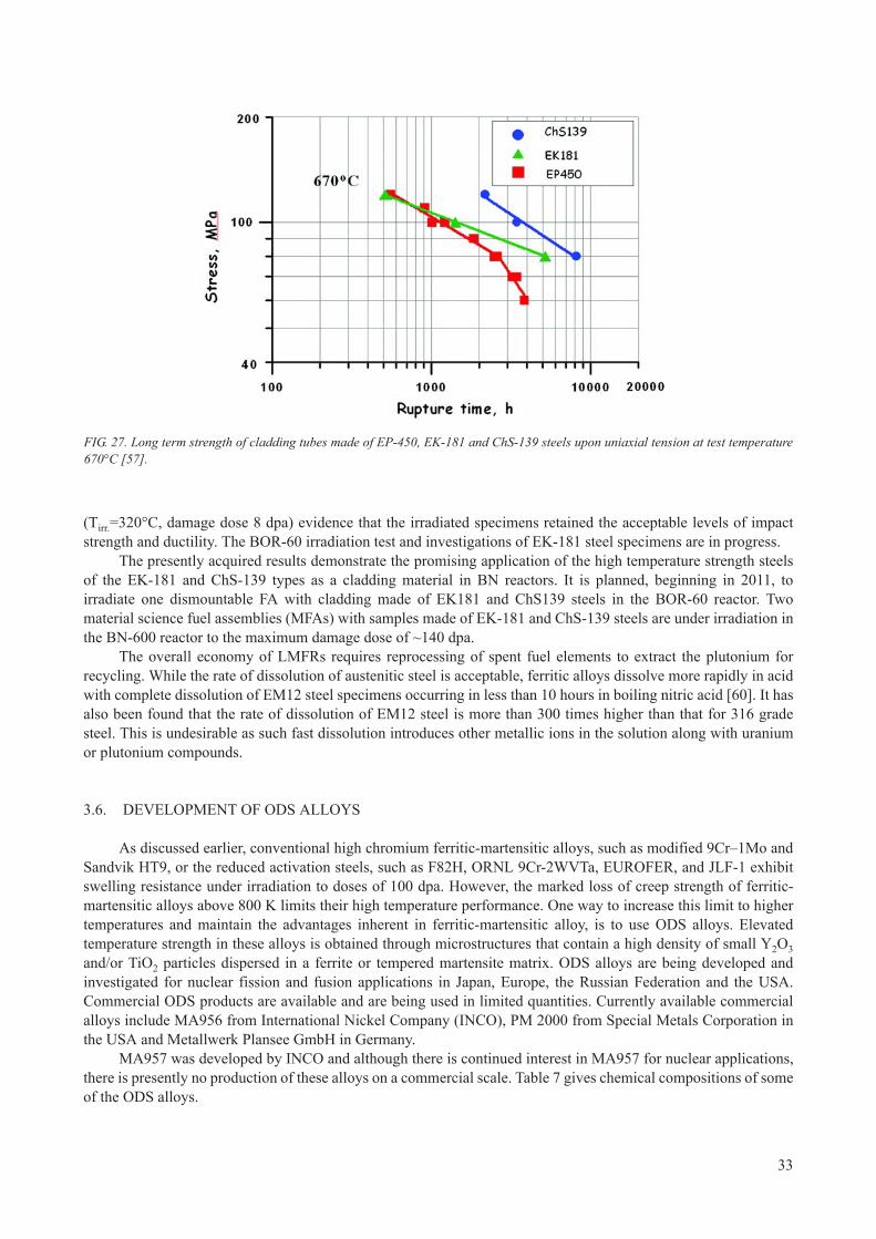
(Тirr.=320°С, damage dose 8 dpa) evidence that the irradiated specimens retained the acceptable levels of impact strength and ductility. The BOR-60 irradiation test and investigations of EK-181 steel specimens are in progress.
The presently acquired results demonstrate the promising application of the high temperature strength steels of the EK-181 and ChS-139 types as a cladding material in BN reactors. It is planned, beginning in 2011, to irradiate one dismountable FA with cladding made of EK181 and ChS139 steels in the BOR-60 reactor. Two material science fuel assemblies (MFAs) with samples made of EK-181 and ChS-139 steels are under irradiation in the BN-600 reactor to the maximum damage dose of ~140 dpa.
The overall economy of LMFRs requires reprocessing of spent fuel elements to extract the plutonium for recycling. While the rate of dissolution of austenitic steel is acceptable, ferritic alloys dissolve more rapidly in acid with complete dissolution of EM12 steel specimens occurring in less than 10 hours in boiling nitric acid [60]. It has also been found that the rate of dissolution of EM12 steel is more than 300 times higher than that for 316 grade steel. This is undesirable as such fast dissolution introduces other metallic ions in the solution along with uranium or plutonium compounds.
3.6. DEVELOPMENT OF ODS ALLOYS
As discussed earlier, conventional high chromium ferritic-martensitic alloys, such as modified 9Cr–1Mo and Sandvik HT9, or the reduced activation steels, such as F82H, ORNL 9Cr-2WVTa, EUROFER, and JLF-1 exhibit swelling resistance under irradiation to doses of 100 dpa. However, the marked loss of creep strength of ferritic-martensitic alloys above 800 K limits their high temperature performance. One way to increase this limit to higher temperatures and maintain the advantages inherent in ferritic-martensitic alloy, is to use ODS alloys. Elevated temperature strength in these alloys is obtained through microstructures that contain a high density of small Y2O3
and/or TiO2 particles dispersed in a ferrite or tempered martensite matrix. ODS alloys are being developed and investigated for nuclear fission and fusion applications in Japan, Europe, the Russian Federation and the USA. Commercial ODS products are available and are being used in limited quantities. Currently available commercial alloys include MA956 from International Nickel Company (INCO), PM 2000 from Special Metals Corporation in the USA and Metallwerk Plansee GmbH in Germany.
MA957 was developed by INCO and although there is continued interest in MA957 for nuclear applications, there is presently no production of these alloys on a commercial scale. Table 7 gives chemical compositions of some of the ODS alloys.
FIG. 27. Long term strength of cladding tubes made of EP-450, EK-181 and ChS-139 steels upon uniaxial tension at test temperature 670°С [57].
33

3.7. HISTORY OF LMFR FUEL ASSEMBLY CLADDING MATERIALS PROGRAMMES
Each of the nations involved in LMFR operation have taken paths that sometimes parallel the paths of others and sometimes were different. In alphabetical order, a summary is presented of the various national experiences and current activities that are underway.
3.7.1. China
Research and development activities on structural materials for LMFR fuel assembly was initiated in the 1990s along with construction of the CEFR. Based on information and experiences available from published sources, the China Institute of Atomic Energy selected a Ti-modified 316 similar to D9 with ~20% cold working to serve as the first generation fuel assembly structural material.
Experimental cladding tubes were manufactured in collaboration with Shanghai Baosteel Group Cooperation. Out of pile tests included tensile tests from room temperature to 650°C, high temperature creep tests between 550°C and 700°C and high temperature 1% creep rupture tests between 550–700°C up to 10000 hours. Subsequently, cladding tubes were subjected to fast neutron irradiation in BOR-60 (flux: 1.8 × 10¹⁵ n·cm–2·s–1) under sodium at 330–550°C to 18 dpa. The results of ring-pull tensile tests showed no deterioration of the mechanical properties following irradiation. Other irradiation tests are in progress.
Developmental activities on ODS alloys are underway in the China Iron and Steel Research Institute Group, General Research Institute for Non-ferrous Metal and Beijing University of Science and Technology. The ODS alloy has a composition of 13Cr–2.2Ti–1.5Mo–0.5 YO2O3 and has been prepared and subjected to ion beam irradiation with He and Fe ions.
TABLE 7. CHEMICAL COMPOSITION OF SOME ODS ALLOYS
Element 12Y1 12YWT MA956 MA957 PM 2000
C 0.045 0.05 0.03 0.03 0.01
Mn 0.04 0.06 0.06 0.09 0.11
P <0.001 0.019 0.008 0.007 <0.002
S 0.002 0.005 0.005 0.006 0.0021
Si 0.03 0.18 0.05 0.04 0.04
Ni 0.24 0.27 0.11 0.13 0.01
Cr 12.85 12.58 21.7 13.7 18.92
Mo 0.03 0.02 <0.05 0.03 0.01
V 0.007 0.002
Ti 0.003 0.35 0.33 0.98 0.45
Co 0.005 0.02 0.03 0.01
Cu 0.01 0.02 0.01
Al 0.007 5.77 0.03 5.10
B 0.004 0.009 <0.0003
W <0.01 2.44 0.04
Zr 0.003 <0.01
N 0.017 0.014 0.029 0.044 0.0028
O 0.15 0.16 0.21 0.21 0.25
Y 0.20 0.16 0.38 0.28 0.37
Note: balance, iron.
34
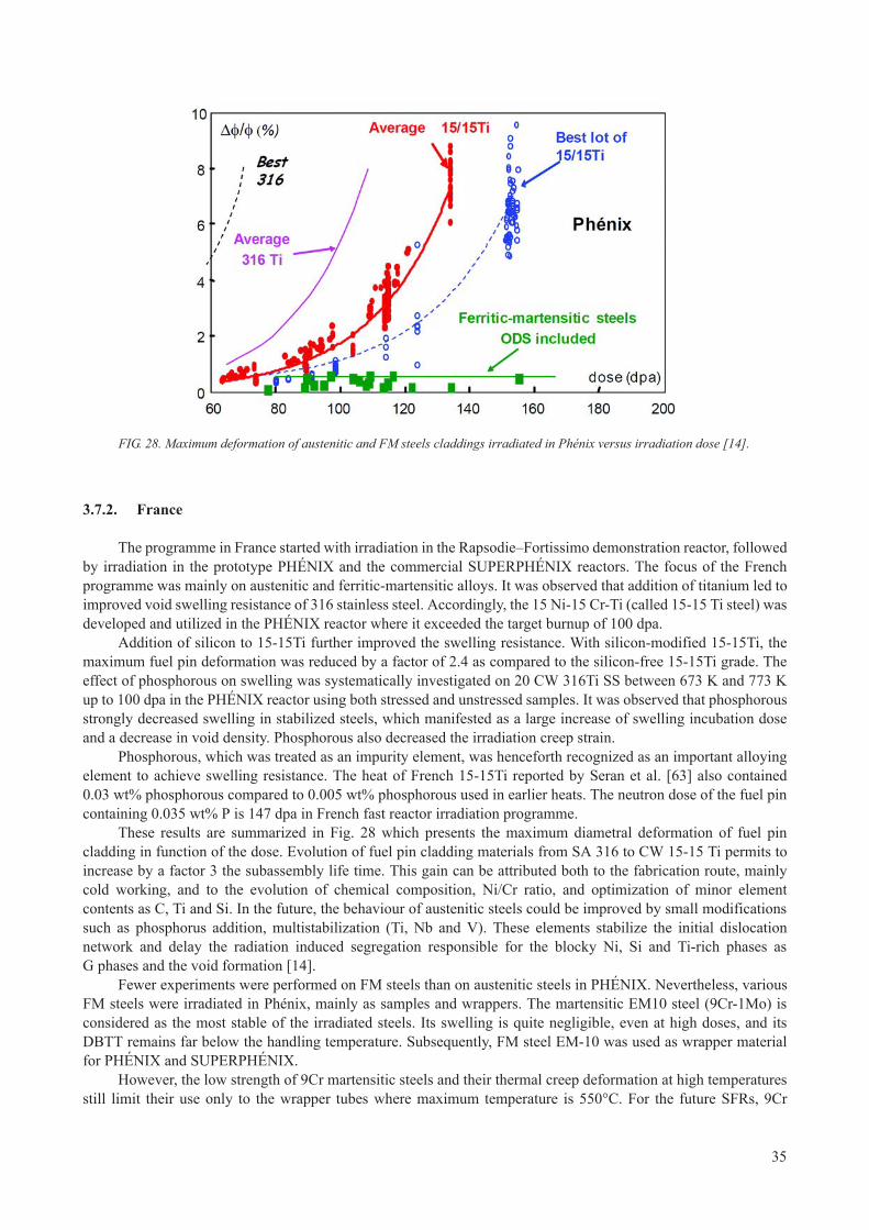
3.7.2. France
The programme in France started with irradiation in the Rapsodie–Fortissimo demonstration reactor, followed by irradiation in the prototype PHÉNIX and the commercial SUPERPHÉNIX reactors. The focus of the French programme was mainly on austenitic and ferritic-martensitic alloys. It was observed that addition of titanium led to improved void swelling resistance of 316 stainless steel. Accordingly, the 15 Ni-15 Cr-Ti (called 15-15 Ti steel) was developed and utilized in the PHÉNIX reactor where it exceeded the target burnup of 100 dpa.
Addition of silicon to 15-15Ti further improved the swelling resistance. With silicon-modified 15-15Ti, the maximum fuel pin deformation was reduced by a factor of 2.4 as compared to the silicon-free 15-15Ti grade. The effect of phosphorous on swelling was systematically investigated on 20 CW 316Ti SS between 673 K and 773 K up to 100 dpa in the PHÉNIX reactor using both stressed and unstressed samples. It was observed that phosphorous strongly decreased swelling in stabilized steels, which manifested as a large increase of swelling incubation dose and a decrease in void density. Phosphorous also decreased the irradiation creep strain.
Phosphorous, which was treated as an impurity element, was henceforth recognized as an important alloying element to achieve swelling resistance. The heat of French 15-15Ti reported by Seran et al. [63] also contained 0.03 wt% phosphorous compared to 0.005 wt% phosphorous used in earlier heats. The neutron dose of the fuel pin containing 0.035 wt% P is 147 dpa in French fast reactor irradiation programme.
These results are summarized in Fig. 28 which presents the maximum diametral deformation of fuel pin cladding in function of the dose. Evolution of fuel pin cladding materials from SA 316 to CW 15-15 Ti permits to increase by a factor 3 the subassembly life time. This gain can be attributed both to the fabrication route, mainly cold working, and to the evolution of chemical composition, Ni/Cr ratio, and optimization of minor element contents as C, Ti and Si. In the future, the behaviour of austenitic steels could be improved by small modifications such as phosphorus addition, multistabilization (Ti, Nb and V). These elements stabilize the initial dislocation network and delay the radiation induced segregation responsible for the blocky Ni, Si and Ti-rich phases as G phases and the void formation [14].
Fewer experiments were performed on FM steels than on austenitic steels in PHÉNIX. Nevertheless, various FM steels were irradiated in Phénix, mainly as samples and wrappers. The martensitic EM10 steel (9Cr-1Mo) is considered as the most stable of the irradiated steels. Its swelling is quite negligible, even at high doses, and its DBTT remains far below the handling temperature. Subsequently, FM steel EM-10 was used as wrapper material for PHÉNIX and SUPERPHÉNIX.
However, the low strength of 9Cr martensitic steels and their thermal creep deformation at high temperatures still limit their use only to the wrapper tubes where maximum temperature is 550°C. For the future SFRs, 9Cr
FIG. 28. Maximum deformation of austenitic and FM steels claddings irradiated in Phénix versus irradiation dose [14].
35

martensitic steels will be used for wrapper tubes and probably ODS alloys for fuel pin cladding currently under development.
R&D activities are underway for developing Fe-9-18Cr–ODS material in order to achieve doses as high as 150–200 dpa without failure. Both martensitic and ferritic ODS alloys are being developed. The ferritic ODS exhibits a higher DBTT compared to the martensitic ODS and has better corrosion resistance. The new programme developed since 2007 by CEA in collaboration with EDF and AREVA on development of a new ODS ferritic-martensistic alloys is under way [64]. These new ODS alloys have been introduced with other ODS as MA956, MA957 as samples (tensile, impact) in an experimental rig in PHÉNIX for the last cycle. The maximum dose is low, 17 dpa, compared to the target dose for ASTRID and SFR cladding, higher than 150 dpa. However, this dose is sufficient to compare mechanical behaviour under irradiation of the ODS alloys and study the effects of different parameters (Cr content, yttria level, fabrication route) on mechanical properties and microstructural evolutions.
3.7.3. India
The focus of the Indian programme on structural materials for LMFR fuel assembly has focused on SS316 and its modified version known as D9. The 40 MW(th) FBTR, which has been in operation since October 1985, contains fuel assembly structural components made of SS316 in the 20% CW condition. FBTR fuel assemblies using 20% CW SS316 cladding tubes and wrappers have demonstrated satisfactory performance to a burnup of 155 GWd·t–1, corresponding to a maximum displacement damage of 86 dpa for the cladding.
The 500 MW(e) PFBR, which is under construction and likely to be commissioned in 2011, will use stainless steel type D9 in the 20% CW condition as fuel cladding and wrapper tubes.
Industrial scale manufacturing of D9 cladding tubes and wrappers are underway. Simultaneously, for future cores of PFBR, a modified version of D9 known as D9I with phosphorus addition is being developed. For future commercial LMFRs an ODS steel is being developed for the cladding material and FM T91 is being developed as a wrapper material.
Ion beam radiation with a 1.7 MV Tandetron accelerator is being used for developmental studies on advanced structural materials.
3.7.4. Japan
The LMFR programme in Japan was initiated with the 100 MW(th) JOYO reactor which was subsequently upgraded to 140 MW(th). JOYO was followed by the prototype MONJU reactor. Japan initiated the Fast Reactor Cycle Technology Development Project (FaCT) in 2006. Under the auspices of FaCT a conceptual design of a commercial Japanese sodium fast reactor (JSFR) is underway. Figure 29 summarizes the core component materials to be used in the SFR in Japan.
Type 316 SS was the early choice of material for fuel cladding and wrapper tubes in the Japanese fast reactor programme. The requirement for high fuel burnup motivated the development of advanced austenitic stainless steels, which are capable of withstanding about 150 dpa of neutron damage and 150 appm of transmutation produced helium. Extensive studies carried out in Japan have shown that void swelling of 20% CW 316 stainless steel decreased significantly by increasing the phosphorous level from 0.003–0.03 wt%. The beneficial effect of titanium tends to saturate above a Ti/C ratio of 2 for 20% CW 316 SS.
Based on these findings, a modified 316 SS was specified with composition of Fe-16Cr-14Ni-2.5Mo-0.06C-(0.7-0.8)Si-0.025P-0.004B-0.1Ti-0.1Nb. This material is designated as PNC316. Performance analyses have demonstrated that satisfactory behaviour of PNC316 SS fuel pins can be reached in MONJU at a peak fuel burnup of 131000 MWd·t–1 and a fast neutron fluence of 2.3 × 1027 n·m–2.
Further development of PNC316 was carried out by increasing nickel from 14–20 wt% and increasing titanium from 0.10 to 0.25 wt%. The second generation advanced steel has a nominal composition of Fe-15Cr-20Ni-0.25Ti-0.1Nb-2.5Mo-06C-0.025P-0.004B and is designated as PNC1520. This steel was irradiated in the FFTF and JOYO fast reactors to a neutron dose as high as 210 dpa. At temperatures greater than 773 K, phosphorous, silicon and titanium bearing CW austenitic steels showed significant swelling suppression even after 210 dpa. The optimum level of silicon for suppressing swelling is 0.8 wt%. Only at this higher level of silicon, was an increased amount of nickel found to be beneficial in suppressing swelling.
36

Towards the end of 1990, Japan initiated R&D activities on ODS ferritic alloys for fuel pin cladding tubes to endure displacement damage up to 250 dpa and temperatures as high as 973 K [65]. As part of the feasibility study for a commercial fast reactor, Japan initially selected both 12 Cr-ODS and 9 Cr-ODS steels (as primary candidate material for cladding tubes). Material irradiation tests of ODS have been conducted in the experimental reactor Joyo. Several lots of ODS steels in material specimens have been irradiated by the core material irradiation rigs (CMIRs). In-pile creep rupture tests with pressurized tube specimens have been carried out by the material testing rigs with temperature control (MARICO). The irradiation effect on creep rupture strength is negligible up to 20 dpa and for 196 EFPDs. In order to confirm the irradiation behaviour of ODS steels and thus judge their applicability to fuel claddings, ODS cladding fuel pins have been irradiated in BOR-60 with vibro-packed mixed uranium plutonium oxide (MOX) fuel. A total of 18 fuel pins with ODS claddings have been irradiated at BOR-60 in sequential three tests under a collaborative programme between the Research Institute of Atomic Reactors (RIAR) and the JAEA. The maximum burnup is 11.9 at.% and the maximum dose is 51 dpa. One fuel pin was ruptured in the vicinity of peculiar microstructure change area of 9Cr-ODS cladding. Complex effect of inhomogeneity occurred in ODS cladding manufacturing with mechanical alloying method and higher irradiation temperature than planned may cause the peculiar microstructure change. The development of ODS cladding manufacturing will be continued to improve its homogeneity.
3.7.5. Republic of Korea
In the Republic of Korea, R&D activities on fuel for sodium cooled fast reactors were initiated in 2007 and focused on metallic fuel and FM alloy as fuel assembly structural material. A grade 92 alloy (9Cr–0.5Mo–1.8 W–VNb) has been developed as the candidate material for fuel cladding. Experimental ingots of grade 92 alloy were prepared by vacuum induction melting, followed by hot-rolling at 200°C, normalizing at 1050°C for one hour and tempering at 750°C for two hours. The out of pile mechanical properties of these alloys were found to be satisfactory. Based on this experience, steel cladding tubes were manufactured by melting, hot forging, hot extrusion, cold pilgering and HT. Large scale manufacturing of FM alloy cladding tubes will be initiated in 2011.
3.7.6. Russian Federation
In the Russian Federation, BOR-60 is the main test reactor for irradiation testing of LMFR fuels and structural materials, but performance data from other fast reactors has been very informative. These are BR-5
FIG. 29. Core component materials in the Japanese SFR programme.
37

(commissioned in 1959, upgraded to BR-10 in 1973 and decommissioned in 2006), BN-350 prototype LMFR in Kazakhstan — previous USSR (decommissioned in 1990) and currently operating BN-600. Since 1980 the reactor BN-600 is under operation at Beloyarsk NPP. Design lifetime BN-600 expired in April 2010. At present, the BN-600 lifetime is extended up to 2020. According to the plans the fourth power unit at Beloyarsk NPP with the fast breeder reactor BN-800 shall be put into operation in 2014. The development of a higher power unit with the next generation SFR BN-1200 is in progress.
The first complex programme for the developing of irradiation resistant materials was aimed to obtain materials providing for the burnup not lower than 10 at.% [57]. In the frame of the programme the following steels have been tested: austenitic steel in various states of thermomechanical treatment — 08Cr16Ni11Mo3, 08Cr16Ni11Mo3Ti, 06Cr16Ni15Mo3Nb (EI847), 06Cr16Ni15Mo3NbB (EP172), 06Cr16Ni15Mo2Mn2TiVB (ChS68); FM steels 1Cr13Mo2NbVB (EP450), 05Cr12Ni2Mo, 16Cr12MoWSiVNbB (EP823); and high-nickel alloys with 30–40% nickel. In 1987, the decision was taken to use in BN-350 and BN-600 reactors steels ChS68 CW and EP450 as standard materials for fuel cladding and FA wrappers, respectively.
Currently, for the BN-type reactors the improved austenitic and FM steels including those produced by the PM method (ODS steels) are considered as promising structural materials for further increase of fuel burnup.
The early designed and well-studied EI847 steel (Table 4) was taken as a base for developing of the new austenitic steels. The EP172 steel was obtained by modifying of EI847 with boron (0.003–0.008%). EI847 was also used to develop the ChS68 steel, doped with (aside from boron) silicon and titanium that favourably influence the steel behaviour under irradiation. The new EK164 steel has a higher content of nickel and is multialloyed with titanium, niobium, vanadium, boron, silicon, phosphorus and cerium. Simulation experiments with the austenitic steels carried out under identical conditions have demonstrated that EK164 has a less propensity for the swelling.
Irradiation resistant steels are being designed with account for the following structural factors that control their swelling:
— A solid solution factor determined by a matrix solid solution concentration of alloying (primarily Ni) and impurity elements (С, Nb,Ti, B, Si etc.) that form a ‘point defect-impurity’ complex with changed diffusion characteristics;
— A phase instability factor that manifests itself as formation of precipitate particles, the nature, composition, volume fraction, morphology and localization of which in many respects govern the process of pore nucleation and growth;
— A dislocation factor when cold work increases the density of point defect dislocation sinks and substantially delays the onset of an intensive pore formation.
Structure factors that control swelling are specifically interrelated and influence one another. That is why, the problem of increasing the irradiation resistance of austenitic steels is resolved by optimizing those factors. The results of the PIEs have revealed that the approach basing on the use of the above factors allowed a substantial reduction in austenitic steel swelling.
Currently experimental and standard BN-600 FAs are used to validate the performance of austenitic steel claddings: ChS68 steel (up to ~90 dpa), EK164 steel (up to ~110 dpa). The higher fuel burnup with austenitic steels may be restricted due to their swelling at high damage doses. Hence, the main efforts of materials-scientists are focused on the studying of practically non-swelling 12% Cr steels. The presently acquired results demonstrate the promising application of the high temperature strength steels of the EK181 and ChS139 types as a cladding material in BN reactors. With the aim of attaining the damage dose of ~180 dpa 12% Cr ODS steels are under development. The required higher characteristics of creep and long term strength are achieved via the strengthening of a matrix with dispersed particles of yttrium and titanium oxides. The fabrication process of ODS FM steels on the base of EP450 steel has been developed. A large scope work is focused on the mastering the fabrication process and complex out of pile investigations of fuel pin tubes of the FM ODS steels and their weldments. The ODS samples are under irradiation in BN-600 reactor within two materials FAs up to the damage dose of ~140 dpa beginning in 2010.
38

3.7.7. USA
Development activities for fast reactors were initiated in the 1960s with commissioning of the experimental breeder reactor II (EBR-II). Extensive irradiation testing of a wide variety of fuel structural materials was carried out in EBR-II and later in FFTF.
The initial choice of structural material was austenitic stainless steel AISI 316 with ~20% cold-work to replace the 304 stainless steel that was originally used in EBR-II and stated for use in FFTF, although it was not used in FFTF after void swelling was discovered. The United States National Cladding and Duct Development Programme was set up for providing improved fuel assembly structural materials for services using 20% CW 316 as the reference material.
In the initial phase a wide range of austenitic alloys, ferritic alloys and PH Fe-Ni alloys were investigated using charged particle simulation and irradiation in EBR-II and FFTF. Swelling, irradiation creep, radiation phase stability and effects of irradiation on mechanical properties were examined, focusing eventually on the austenitic alloy D9, a 15 Cr-15 Ni stainless steel stabilized with titanium. PH alloys, D-66 (similar to Nimonic PE-16) and D-68 (Inconel-706) were evaluated in great detail but later discarded as candidates.
The ferritic class included the commercial HT-9 alloy. The ferritic alloys were found to have greatly reduced swelling compared to the reference CW 316 alloy. Accordingly, HT-9 alloys were used for the clad and duct materials for FFTF. However, HT-9 was found to have some limitations in high temperature creep strength, low temperature fracture toughness and susceptibility to fuel cladding chemical interaction.
HT-9 was extensively tested in FFTF by inserting a group of fuel assemblies in a sub-core although the high temperature weakness of the alloy required that the core be de-rated from 400–280 MW. Reaching doses as high as 155 dpa, the assemblies performed flawlessly.
Towards the end of the US programme, several ODS alloys were also identified as advanced structural candidate materials. MA957 received the most attention and a moderate amount of data has been published [66–67]. More recently a number of programmes have started up in the USA focusing on a variety of ODS alloys, although these efforts are hampered by lack of a reactor in which to explore their radiation performance. A review of the various ODS activities with US involvement has recently been published [68].
4. MANUFACTURING TECHNIQUES FORSTRUCTURAL COMPONENTS OF LMFR FUEL ASSEMBLIES
The stringent specifications of the structural components of LMFR fuel assembly, including fuel cladding tube and wrapper, call for careful selection of manufacturing techniques and a strict regime of quality control and assurance throughout the material processing steps. Restricted chemistry, low inclusion content, desired microstructure, close dimensional tolerances and near zero defect product quality are some of the critical requirements in the products for application as fuel cladding and wrapper for LMFRs. The first step consists of preparation of the ingots of the structural material.
Austenitic and ferritic stainless steel ingots are prepared by the ‘melting and casting’ route. When making ODS steel ingots are currently manufactured by the PM process using ferritic steel and Y2O3 and TiO2 as starting materials. The process steps beyond the ingots stage are more or less common and include hot-extrusion, pilgering-HTcycle and drawing. An overview of the manufacturing steps is presented.
39

4.1. FABRICATION OF INGOTS
4.1.1. Melting practices (for austenitic and ferritic stainless steels)
Internationally accepted melting practices to achieve the controlled composition and low inclusion content consists of electric arc furnace (EAF), air induction melting (AIM) and vacuum induction melting (VIM) as primary melting techniques depending on the alloy compositions. The primary melting technique facilitates the major part of compositional control and refining in terms of alloying elements and impurities, respectively. These practices are followed by secondary refining techniques such as vacuum induction refining (VIR), vacuum arc re-melting (VAR), electro slag refining (ESR), argon oxygen decarburization (AOD) or vacuum oxygen decarburization (VOD) depending on the level of trace elements and gaseous impurities that will be tolerated.
In modified D-9, which is a major cladding and wrapper tube material for Indian LMFRs, the stringent compositional control is achieved by a combination of VIM followed by VAR. VIM is preferred over air induction melting because the latter technique does not provide direct control over the amount of titanium that can be recovered into the melt. Titanium easily undergoes oxidation in air and lost into the slag. VIM takes mild steel scrap of suitable basic composition with respect to sulphur and phosphorous content and pure (up to 99.8%) alloying elements such as Cr, Ni, Mo, Ti and Nb for various grades. The composition of the whole charge should be known accurately before the start of the melting.
Induction melting is carried out under vacuum with a power source of frequency between 500–2500 cycles·s–1.C, Si, Mn, P are maintained in the modified D9 material at specified ranges to obtain desired mechanical properties and resistance to void swelling. Pure graphite is added during the melting to increase the carbon content. The upper limit of carbon is maintained by addition of Fe2O3 to the melt so as to remove C in the form of CO or CO2
depending on the temperature of the melt. The specified range of Si is maintained by addition of pure Si during VIM. Mn composition is controlled with the addition of electrolytic grade Mn (98.5 wt%). Addition of Mn is avoided in vacuum as its vapour pressure is rather high. It is added only under high argon pressure in later stages during final adjustment of chemical composition. Mild steel scrap taken as the initial charge contains phosphorus of ~0.03%. Modified D9 contains high phosphorus in the range of 0.025–0.04 wt%. Hence, Ferro-phosphorus containing 26% P is added into VIM. Boron content in the modified D9 has been recommended to be in the range of 40–60 appm. The addition of B in the melt can be done by adding Ferro-Boron containing 18% B. However, once introduced, the B content cannot be reduced from the melt by any method. Hence the initial B content in the charge has to be suitably estimated.
Secondary refining is carried out on the primary melted ingots by VAR. A consumable electrode is progressively melted under vacuum to achieve the desired ingot quality with lower N2 , H2 and O2 content. VAR essentially lowers the inclusion content of globular oxide.
316LN and 304LN stainless steels are often chosen for structural components of the reactor assembly. These grades of steels are primarily made by combination of AIM followed by ESR. The Cr, Mo and C contents have been specified taking into account corrosion resistance criteria from operating experience with nuclear reactors. Basic composition of the charge depends on the selection of low phosphorus and low C grade mild steel scrap. The initial charge is added with Ni and Mo pellets of 99.9% purity.
316LN and 304LN steels have been designed to contain lower limits of C and N to ensure that mechanical properties match those of 304L and 316LN grades. An upper limit of C is specified to ensure freedom from sensitization during welding. The upper limit of N is put at 0.08 wt% mainly on consideration of weldability and to minimize scatter in mechanical properties. Cr content is maintained with addition of low carbon ferro-chrome containing 65%Cr. Also high nitrogen ferro-chrome containing 65% Cr and 3.25 wt% N is used in the melt to control Cr with higher nitrogen content in stainless steel.
Primary air induction melted ingots are fabricated into the form of consumable electrodes and secondary ESR is carried out in dry air. ESR is preferred in 304LN and 316LN grades of steels mainly to achieve a stringent sulphide (A-type) inclusion rating. Ingots obtained after ESR essentially maintain the same chemistry with respect of N2 and H2. However, the sulphide content is brought down significantly, which is of major concern during welding of 316LN and 304LN steels. Refining in ESR is carried out by maintaining a suitable composition of a prefuse slag. The prefuse slag mainly consists of CaF2, CaO and Al2O3 in varying proportions, which are essentially reducing in nature. Desulphurization mainly depends upon the content of CaO in the slag whereas CaF2 and Al2O3
provide fluidity and electrical resistivity to the melt respectively. Commercially, CaF2: CaO: Al2O3 are used in
40

70:15:15, 60:20:20 or 33:33:33 proportions depending on the primary ingot quality. The dry air above the melt help to prevent the hydrogen pick up in normal atmosphere.
4.1.2. PM route for ODS steels
The ODS steels of ferritic and ferritic-martensitic types have so far been manufactured on a laboratory scale (~10 kg batch) or pilot plant scale (~1 ton) in France, Japan and the Russian Federation. The manufacturing process consists of two steps:
— PM route for preparation of ingots followed by manufacturing of mother tubes;— Cold rolling (including pilgering) of mother tubes to cladding tubes.
The process flow sheet followed on a laboratory scale (10–30 kg) for preparation of ingots and mother tube is shown in Fig. 30.
The process consists of mechanical alloying of argon gas atomized powder of ferritic steel and Y2O3 in an attritor or ball mill. The starting powders are sieved up to 150 micron followed by putting the powder mixture into mild steel cans, degassing at 673 K, followed by hot extrusion at 1423 K and annealing. Precipitation of nano-clusters of oxide particles occur during the consolidation process.
The extruded bars are then machined and drilled to produce mother tubes. The mother tubes are then subjected to multiple cold rolling-HT cycles, as shown in Fig. 31 to obtain cladding tubes of the desired size of outer and inner diameters and wall thickness.
In recent years, Japan has carried out the manufacture of ODS steel on a one ton scale. The process consists of mechanical alloying of the feed ferritic stainless steel and yttria powders in ball mill of capacity of one ton followed by hot isostatic pressing. The billets are then hot extruded in a commercial 5600 t press. Each mother tube of ~65 mm and 48 mm outer and inner diameter and 10 m in length is used produce ~100 cladding tubes of ~8 mm outer diameter, 7.5 inner diameter and 2 m in length.
4.2. FORGING
In case of stainless steels, forging is used as a primary working step, which gives several advantages in the final properties at the finished stage. Forged steel is considerably stronger, more ductile, with considerable gain in the fatigue resistance than those steels produced by alternate methods.
FIG. 30. Process flow sheet for manufacturing ODS steels mother tube by PM route.
41

The as-cast structure of the secondary cast melted stainless steel ingot is extremely coarse. Also, the various alloying elements and trace impurities present in the stainless steel segregate even during the best secondary melting process. The forging leads to a refinement of grain structure that improves the physical properties of the final product. A proper design can go a long way in orienting the grain flow in the direction of the main stresses. In this process, the material undergoes controlled plastic deformation and the grains elongate or flow and produce a fiber-like structure. This grain flow increases the strength of the metal in the flow directions. This method is used to make components where high strength-to-weight ratio is required for critical applications in fast reactors.
Workability, which refers to the ease with which a material can be shaped by plastic flow without the onset of fracture, is an important parameter and includes all other qualities such as forgeability, rollability, extrudability and formability (sheet metal working). Workability is influenced not only by the microstructure of the material, applied temperature, strain rate and strain, but also by the stress state in the deformation zone.
A processing map is an explicit representation of the response of a material, in terms of microstructural mechanisms, to the imposed process parameters and consists of a superimposition of power dissipation and an instability map. These maps are developed based on the dynamic materials model (DMM). Such a map for metallic materials exhibits several domains that are safe for processing in terms of combination of temperature and strain rate and may also contain regimes of flow instabilities and cracking that should be avoided.
Processing maps and instability maps have been generated for austenitic stainless steels such as type 304L, 316L, 304 and alloy D9, and ferritic steels such as 9Cr-1Mo and modified 9Cr-1Mo steels on the basis of compression test data in cold, warm and hot working regions. These are referred to as DMM maps.
The safe and unsafe working regions for the above materials have been identified from these maps. These regions have been confirmed through detailed microstructural investigations on deformed samples, analysis of flow behaviour of materials and validation through industrial processes such as rolling, forging and extrusion. The ‘safe’ processing regime predicted by processing maps refers to selection of processing parameters in a window in the processing map. The conditions imposed on the parameters ensure stability of deformation and avoid various instabilities such as localized flow, shear bands etc.
As an example, a modified stability map for 316L SS is shown in Fig. 32 (a). The values of activation energy are represented as contours in kJ·mol–1. The grain size of the forged product deformed at 0.15 s-1 is superimposed on the stability map in Fig. 32 (b). Figure 32 (c) shows the variation of ultimate tensile strength (UTS) of the forged product with forging temperature. The grain size variation as well as UTS variation is minimal in the ‘stable domain’ which ensures that the changes in the temperature and strain rate will not affect the product properties significantly.
FIG. 31. Multi-stage pilgering HT cycle for production of ODS cladding tubes from the mother tube.
42

FIG. 32. DMM stability map for 316L stainless steel [69].
43

4.3. MANUFACTURE OF SEAMLESS TUBES
Seamless tubes of different dimensions are being used as cladding and structural components in the fuel assemblies for fast breeder reactors. Critical quality requirements for the tubular products are:
— Close dimensional tolerances;— Restricted chemistry;— Good surface finish;— High degree of cleanliness;— Material soundness.
These requirements make it mandatory for the manufacturers of these tubes to possess special manufacturing/testing equipment, infrastructure, expertise and most vitally, extensive processing ‘experience’. At every stage of the process flow sheet, namely, billet preparation, hot expansion, hot extrusion of billets into hollows, cold pilgering/cold drawing to finished sizes, cleaning, solution annealing and straightening, care must be taken for strict compliance with processing parameters to obtain products of the desired quality.
Structural materials used for fuel assemblies contain high amounts of alloying elements such as Mo, N, Ni and Ti. This results in reduction of hot ductility coupled with an increase in flow stress leading to poor hot working characteristics. For achieving the required properties, it is essential that the microstructural development during deformation should be carefully controlled and that defects and flow instabilities are avoided. Among all the mechanical processing methods, the bulk metal working stage, namely, forging, rolling and extrusion is considered to be of primary importance for two reasons. Firstly, in this stage, major microstructural changes occur and these have a profound influence on the subsequent processing steps. Secondly, in view of the large tonnage of material being processed by bulk metalworking, any improvement in processing techniques has a multiplying effect on the overall productivity in manufacturing.
In extrusion, interaction of the billet with the container and the die results in high compressive stresses, which are effective in reducing the cracking of materials during primary breakdown from the ingot. A typical extrusion press of capacity 40 kN is shown in Fig. 33. Tubes are produced either by starting with a hollow billet or by a two-step extrusion operation in which a solid billet is first pierced and then extruded. The ram speed is an important parameter since high ram speeds are required in high temperature extrusion where there is a problem of heat transfer from the billet to the tools. Ram speeds of 0.4–0.6 m·s-1 are typically used in extruding stainless steels.
Considerable effort is required to develop techniques for design and optimization of bulk metal working processes. The ultimate objective is to manufacture components with controlled microstructure and properties, without macrostructural or microstructural defects, on a repeatable basis in a manufacturing environment. It has been observed that defects produced during hot working are usually carried through into cold working deformation and their removal is difficult, if not impossible. Therefore, optimization of processing parameters during thermomechanical processing is very important to get a defect free product.
Numerous investigations have been oriented towards the optimization of processing parameters for stainless steels either by physical or mathematical modelling. These studies have led to the understanding of the mechanism of hot deformation. In case of D9 steel, the processing maps in the temperature range of 900–1250C are shown in Fig. 34 (a). The safe region for working has been identified using this process map. Commonly strain rates of the order of 1–10 s–1 are used for extrusion. Due to the high temperature, i.e. greater than 900C, higher speeds of extrusion results in high strain rates which are on the order of 5–10 s–1. Although D9 has a wide working range, due to the narrow band of attainable stain rate the selection of the extrusion temperature becomes critical.
4.4. COLD PILGERING
Cold pilgering is a quite complex tube forming operation where the metal undergoes a long series of small incremental deformations resulting in both diameter and thickness reduction. It is generally chosen for its
44

dimensional accuracy and favourable texture development, controlled by the ratio of diameter to thickness reduction.
Figure 35 shows the pilgering process schematically. The internal surface is calibrated by a horizontal axisymmetric mandrel, held by a mandrel rod; the evolution of its diameter along the rolling direction (‘profile’) is one of the parameters controlling the final tube quality. The external surface is shaped by two dies with non-axisymmetric grooves, located in a back and forth moving ‘saddle’. The die rotation and translation are synchronized by a rack and pinion system, giving roughly a rolling-without-sliding movement pressing the tube between the die groove and the mandrel.
The most common problems faced in cold rolling operations on stainless steels are edge cracks, waviness, and small sliver defects. In cold forged parts internal cracks are observed, which will affect the performance of the components in service.
FIG. 33. Hot extrusion of stainless steel billet (hollow) preheated to 1473 K temperature.
FIG. 34. (a) Processing map for D9 material showing safe and unsafe (hatched) domains, (b) acceptable microstructure of the material deformed in a safe region,( c) defective microstructure showing flow localization following deformation in an unsafe domain.
45

Figure 36 shows a two roll type pilger mill used for manufacture of seamless stainless steel tubes and also for pilgering of hexagonal wrapper tubes.
FIG. 35. Schematic view of cold pilgering, upper and lower dies (a), rotate around their axis (b), which moves back and forth, they calibrate the outer surface of the tube by their grooves (d). The mandrel (f) calibrates the inner surface of the perform (e), being rolled into a tube (g).
FIG. 36. (a) Two roll type pilger mill used for manufacture of seamless stainless steel tubing, (b) pilgering of hexagonal wrapper tube in progress, (c) die arrangement for two roll (full ring die type) used for stainless steel tube production, (d) die arrangement for 3-roll mill used for making hexagonal tubes.
46
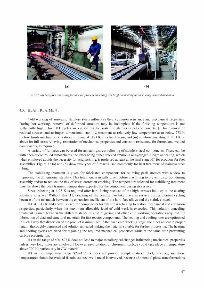
4.5. HEAT TREATMENT
Cold working of austenitic stainless steels influences their corrosion resistance and mechanical properties. During hot working, removal of deformed structure may be incomplete if the finishing temperature is not sufficiently high. Three HT cycles are carried out for austenitic stainless steel components: (i) for removal of residual stresses and to impart dimensional stability, treatment at relatively low temperature at or below 773 K (before finish machining), (ii) stress relieving at 1123 K after hard facing and (iii) solution annealing at 1131 K or above for full stress relieving, restoration of mechanical properties and corrosion resistance, for formed and welded components, as required.
A variety of furnaces can be used for annealing/stress relieving of stainless steel components. These can be with open or controlled atmospheres, the latter being either cracked ammonia or hydrogen. Bright annealing, which when employed avoids the necessity for acid pickling, is preferred at least at the final stage HT for products for fuel assemblies. Figure 37 (a) and (b) show two types of furnaces used commonly for heat treatment of stainless steel tubing.
The stabilizing treatment is given for fabricated components for relieving peak stresses with a view to improving the dimensional stability. This treatment is usually given before machining to prevent distortion during assembly and/or to reduce the risk of stress corrosion cracking. The temperature selected for stabilizing treatment must be above the peak transient temperature expected for the component during its service.
Stress relieving at 1123 K is required after hard facing because of the high stresses built up at the coating substrate interface. Without this HT, cracking of the coating can take place in service during thermal cycling because of the mismatch between the expansion coefficient of the hard face alloys and the stainless steel.
HT at 1311 K and above is used for components for full stress relieving to restore mechanical and corrosion properties, particularly when the maximum allowable level of cold work is exceeded. This solution annealing treatment is used between the different stages of cold pilgering and other cold working operations required for fabrication of clad and structural materials for fast reactor components. The heating and cooling rates are optimized in such a way that distortion of the product is minimized. After each cold working stage, the tubes are cut to proper length, thoroughly degreased and solution annealed making the material suitable for further processing. The heating and cooling cycles are fixed for regaining the required mechanical properties while at the same time preventing carbide precipitation.
HT in the range of 600–823 K does not lead to major metallurgical changes influencing mechanical properties unless very long times are involved. However, precipitation of chromium carbide could take place at temperature above 700 K, particularly in CW material.
HT in the temperature range 823–1123 K does not provide complete stress relief, however, and these temperatures should be avoided if stainless steel weld metal is involved, because of potential phase transformations
FIG. 37. (a) Gas fired annealing furnace for process annealing, (b) bright annealing furnace using cracked ammonia.
47

in the weld metal. HT of weld metal at these temperatures leads to precipitations of carbides, sigma and other embrittling phases. It is advantageous to do stress relieving above 1123 K, since at this temperature carbides, if any, will dissolve and also ~95% the delta ferrite will transform into austenite. HT at these temperatures will also recrystallize cold structures and will generally result in improved ductility and toughness.
4.6. CLEANING (DEGLASSING, PICKLING AND DEGREASING)
Special attention is required in preparing the material before heat treatment to avoid pickup of carbon from the contaminated/unclean surface. Due to pickup of carbon, the corrosion (IGC) properties are severely affected. For this problem, the following cleaning operations are recommended:
— After extrusion, deglassing is carried out using a solution of HF (40% w/w), HNO3 (63% w/w) and water (in
ratio 4:10:86). The same solution can be used for pickling as well if required. This procedure is followed by cleaning using rinsing in cold and hot (60C) de-mineralized water;
— After pilgering (when using an oil-based lubricant): Alkali degreasing (in a mixture of tri-sodium phosphate + sodium gluconate + sodium hydroxide) followed by cold water rinsing for both outside and inside surfaces (industrial water with total dissolved solids as 400 ppm w/w) and finally rinsing in hot (60C) de-mineralized water. Thorough cleaning must be ensured.
4.7. QUALITY CONTROL DURING MANUFACTURING
The following quality control tests are carried out during regular production of tubes:
— Visual and dimensional examinations;— Metallographic and inter granular corrosion test;— Mechanical tests–tensile, bend, flattening, flaring/expansion and hardness test; — Hydrostatic pressure testing; — Non-destructive tests (ultrasonic, eddy current);Chemical composition/check analysis.
4.7.1. Dimensional tolerances
As an example, typical dimensional tolerances for hexagonal wrappers and clad tubes for PFBR are given in Table 8.
TABLE 8. TYPICAL DIMENSIONAL TOLERANCES FOR WRAPPER AND CLAD TUBES OF D9 MATERIAL
Dimension , form Hexagonal, seamless Round, seamless
Inside Width A/F 124.9 ± 0.3 Dia 5.70 ± 0.02
Outside Width A/F 131.6 max Dia 6.60 ± 0.02
Wall thickness 3.2 ± 0.3 0.43
Length 3000 Nominal 2650
Corner radius (inside) 3 ± 0.5 —
Straightness, max. 1/2500 mm or better 0.25/500
Twist between any two cross section separated by one meter
5 max. twist —
48
4.7.2. Microstructure
The metallurgical requirements are stringent with respect to grain size, intergranular attack and carbide precipitation. Grain size is tested according to ASTM E-112 and is maintained in the range of 7–9 prior to final cold work. Finished tubes are subjected to IGC tests as per ASTM A-262 practice A, to verify freedom from visible carbide precipitation. In order to minimize radiation embrittlement and to have better corrosion resistance to liquid sodium, cleanliness of the steel is a prime requirement. The inclusion ratings are made stringent, as shown in Table 9. This is obtained by selection of special steel making processes such as VAR and ESR melting.
4.7.3. Mechanical properties at room temperature and elevated temperature
To ensure high reliability in performance during service at elevated temperature, tensile testing is done at 540°C in addition to room temperature testing. Typical requirements of the mechanical properties are given in Table 10. Hardness is measured by the Vickers microhardness test as per ASTM E-384 and is maintained in the range of 220–290 VHN.
4.7.4. Non-destructive evaluation
The soundness of the tubes are tested ultrasonically with a stringent standard of 0.05 ± 0.002 mm depth, 600
V-shaped notch having maximum length of 1.5 ± 0.07 mm for fuel tubes and 0.1 ± 0.01 mm depth, 600 V-shaped notch having maximum length of 3.5 ± 0.15 mm for hexagonal wrapper tubes. The fuel tubes are subjected to eddy current tests also with the standard having through holes of 0.3 ± 0.03 mm diameter. In both cases tubes with defect indications in excess of 70% of reference are rejected.
Typical flow sheets for manufacture of hexagonal wrapper tubes and fuel clad tubes for 500 MW(e) PFBR under construction in Kalpakkam in India are given below in Figs 38 and 39 respectively.
4.8. WELDABILITY OF STAINLESS STEELS USED IN FUEL FABRICATION
For the fuel pin fabrication, welding is a critical processing step. During the fabrication of fuel welding of the end caps on fuel pins is usually carried out by autogenous TIG welding. The major problem encountered during welding of austenitic stainless steels is hot cracking due to formation of low melting point eutectics arising from the presence of impurities such as sulphur, phosphorous etc.
TABLE 9. INCLUSION RATING FOR D9 MATERIAL
Inclusion type Sulphide type (A) Alumina type (B) Silicate type (C) Globular type (D)
Thin ½ 0 0 ½
Heavy ½ 0 0 ½
TABLE 10. MECHANICAL PROPERTY REQUIREMENTS AT ROOM TEMPERATURE AND ELEVATED TEMPERATURE FOR D9 MATERIAL
Properties At room temp. At high temp. (540°C)
UTS (MPa) 700–830 500–690
YS (MPa) 550–760 430–580
% ELG. (GL=5.65A) 20 min. 10 min.
49
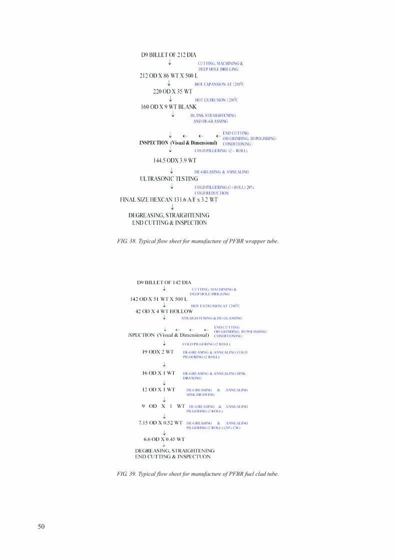
FIG. 38. Typical flow sheet for manufacture of PFBR wrapper tube.
FIG. 39. Typical flow sheet for manufacture of PFBR fuel clad tube.
50

The problem of hot cracking in modified D9 alloy is complicated since phosphorous is specified as a deliberately added alloying element, whereas the sulphur content is constrained to be below 0.001 wt% or even 0.0005 wt%. In addition to these elements, however, other minor alloying elements also have a detrimental effect on the weldability. For example, titanium is known to increase cracking in austenitic stainless steels.
The influence of titanium on hot cracking in alloy D9 was investigated by testing three heats with titanium levels of 0.21 wt%, 0.32 wt% and 0.42 wt% [70]. The hot cracking behaviour was evaluated by employing longitudinal as well as transverse Varestraint tests. Electron probe microanalysis of hot cracks in alloy D9 revealed segregation of Ti, C, N and S on crack faces and on segregated phases, which are present in the inter-dendritic space. Electrochemical extraction followed by X ray diffraction analysis revealed segregation of titanium carbides and nitrides (TiC, TiC0.3N0.7) and carbosulfides Ti2CS and Ti4C2S2 which are likely to form eutectics with austenite and thereby promote cracking.
The relative amount of these phases increased with increasing titanium content, which was particularly high above a Ti/(C+0.857N) ratio of ~3. The factor 0.857 represents the ratio of the mass numbers of C and N. Empirical correlations are available between phosphorous and sulphur contents and hot cracking susceptibility of austenitic stainless steels [71].
In 316LN austenitic stainless steels, hot cracking studies have shown that (P+S) must be controlled to be below 0.03 wt% when the weld solidification takes place in austenite mode so as to avoid the detrimental effects of (P+S) segregation [72].
Another influence of welding is a change of the fracture properties in the weld and heat affected zone. Fracture toughness tests on type 316 steel weld metal over a range of temperatures from 20–550°C has been evaluated by Picker [72]. The effects on toughness due to post-weld HT and thermal ageing are of special significance. The conclusions reached are that type 316 steel possesses a superior toughness to the weld metal in the as-welded or stress-relieved conditions, but the toughness of the steel is degraded to a level similar to that of the weld metal following thermal ageing at temperatures over 600°C.
Relatively short term thermal ageing in the temperature range 370–450°C does not appear to affect the toughness of either type 316 steel or weld metal. Considering the adverse effects of titanium, niobium, copper and boron on weldability, maximum permissible limits on these elements have been imposed, although no limits exist in ASTM specifications. In addition to more stringent composition limits, a specification for inclusions has been added keeping in mind that sulphide inclusions are most detrimental, especially with respect to welding considerations, and globular oxides are deemed to be least harmful.
5. COMPATIBILITY OF STEELS WITHLIQUID METAL COOLANTS
5.1. COMPATIBILITY WITH LIQUID SODIUM
Evaluation of sodium environmental effects on mechanical strength properties is essential to assure structural integrity throughout the designed lifetime in sodium cooled fast reactors. Fuel claddings are particularly affected by sodium, since the cladding is extremely thin and operating temperatures are very high [73]. Therefore, it is important to understand the compatibility of materials with sodium at elevated temperatures. It is imperative that the liquid sodium coolant used has a strict control of chemistry, particularly with regard to elements responsible for liquid metal embrittlement (As, Sb, Bi) and also of carbon and oxygen, which are primarily responsible for degradation of mechanical and corrosion properties. These effects are discussed in the following sections.
5.1.1. Influence of sodium (and its purity) on mechanical properties
The important properties to be considered are creep rupture and low cycle fatigue in sodium containing traces of impurities. Figure 40 shows the effect of sodium pre-exposure plotted in terms of strain and time of exposure. It
51

is observed that the creep rupture of 316 stainless steel is sensitive to the exposure of sodium environment. Higher creep rates are observed in the case of sodium-exposed material as compared to those in air-tests.
5.1.2. Effect of carbon in sodium
Austenitic stainless steels are in contact with high temperature liquid sodium in a fast reactor. In order to understand the carbon transport occurring between various regions of these materials through liquid sodium, an accurate knowledge of the carbon activity-concentration relationship in the austenitic steels is essential. A new method involving equilibration of the steel sample with liquid sodium coupled with the measurement of carbon activity in sodium, employing an electrochemical carbon meter, is reported for the measurement of the carbon potential of the steel at different carbon concentrations in the temperature range of 860–960 K [74]. A new expression is proposed relating carbon activity with the composition of steel. The carbon potential of the mixed carbide is seen to be much lower than that of 18/8 stainless steel. The carbon potential of FBTR cladding material (AISI 316) is likely be of the same order. Thus, the mixed carbide fuel material in FTBR is not likely to carburize the AISI 316 cladding material [74].
5.1.3. Effect of traces of oxygen in sodium
It has been observed that small traces of oxygen in the sodium do not influence the creep rupture properties. Figure 41 shows that up to a temperature of 650C, the influence of oxygen up to 10 ppm is negligible. But beyond this temperature there is a marginal difference in the creep-rupture behaviour. It is observed that at 750C sodium containing oxygen leads to lower creep rupture properties as compared to non-sodium exposed material.
5.1.4. Effect of sodium on low cycle fatigue behaviour on stainless steel
The sodium environment appears to have no effect on the low cycle fatigue behaviour. Figure 42 shows that the low cycle fatigue tests conducted at temperature of 550–700C in sodium and sodium free environments shows that there is a linear relationship (as per the Coffins-Manison relationship) between the plastic strain range p and cycle to failure Nf. There is no difference in the slope of the lines for sodium and non-sodium exposed material. This indicates that the low cycle fatigue behaviour of 316 stainless steel is very much acceptable for its application in the sodium environment.
FIG. 40. Effect of sodium exposure on creep rupture behaviour of SS 316 material [73].
52

5.1.5. Corrosion effect of sodium on austenitic and ferritic steels
Liquid sodium, which is used as the coolant in fast reactors is quite compatible, in the pure state, with the austenitic and ferritic steel structural materials [76]. However, traces of impurities play an important role in the corrosion, mass transport and other processes taking place in the heat transport loops of the reactor. Even parts per million levels of oxygen causes corrosion in the high temperature sections of the loop and the corrosion products get transported through the liquid sodium medium to cooler parts of the loop.
FIG. 41. Effect of sodium containing small quantity of oxygen (compared with air-tests) on creep properties (a) creep rupture and (b) minimum creep rate [75].
FIG. 42. Low cycle fatigue behaviour of 316 stainless steel (as-annealed, and aged condition), when exposed in sodium and sodium free environments.
53

Some of the corrosion products as well as fission products which find their way into sodium oxygen impurity level, but also understand the transport and deposition of radionuclides in the reactor. Thermochemistry of the ternary Na-M-0 systems, where M stands for the components of the structural materials, figure prominently in any analysis of the corrosion of fuel cladding in flowing sodium.
In pure sodium containing low levels of oxygen (a few ppm or less), the corrosion rate is low and this proceeds by the selective leaching of alloying elements [77]. The presence of temperature gradients in the heat transport circuits enhances this process. For understanding of this phenomenon, data on the solubility of the various alloying elements in sodium are required as a function of temperature. Because of their higher solubility, nickel and manganese are preferentially leached out from the steel under low oxygen conditions [78]. The loss of alloying elements makes the -phase unstable and the depleted layer of the austenitic material transforms to ferrite [79]. In fast flowing sodium the kinetics of selective leaching process are controlled by the diffusion of alloying elements in the steel matrix to the corroding surface.
In corrosion conditions in sodium at high temperatures, austenitic stainless steels show the typical mass transfer behaviour caused by a temperature difference. The major alloy elements such as nickel, chromium, manganese and silicon are dissolved into sodium in the higher temperature section that induces weight loss, and these elements precipitate and deposit at the lower temperature section causing weight gain [80].
5.1.5.1. Na-Fe-0 system
The experimental results have shown that up to a temperature of 623 K liquid sodium co-exists with Fe(s) and Na2O(s). Oxygen potential measurements carried out in liquid sodium equilibrated with oxides of iron clearly indicated the appearance of a ternary oxide at temperatures above 623 K [81]. Results of isopiestic equilibration experiments and solid state equilibrations have shown that Na4Fe03 coexists with metallic iron and liquid sodium at 923 K. Differential thermal analyses of liquid sodium samples equilibrated with iron oxides showed a reversible transition at 760 K.
Similar observations were made by Charles et a1. during their studies in Na-Fe-0 system [82]. This is attributed to the appearance of another ternary oxide phase in liquid sodium [83] and similar conclusions were made by Bhat et a1. based on their oxygen potential measurements in sodium using a solid electrolyte technique [84]. With a view to identifying the nature of reactions leading to the formation of ternary oxides, differential scanning calorimetric measurements with varying ratios of oxides of iron and sodium as well as mixtures of Na4Fe03 and sodium were carried out. These results coupled with identifications of the products of solid-state reactions between Na2O(s) and FeO(s) have shown that the reversible transition occurring at 760 K is the appearance of a liquid phase of Na4Fe03. Na4Fe03 co-exists with metallic iron and sodium above 623 K.
5.1.5.2. Na-Cr-0 system
Under the normal operating conditions of a sodium steel circuit, the ternary compound that is observed is NaCrO2. The threshold oxygen level above which this compound would form is an important parameter. This can be obtained by measuring the oxygen potential in Na-[Cr]-NaCr02 phase field or can be deduced from the free carbides of chromium which are very stable and participate in the equilibrium leading to the formation of NaCrO2(s). The following observations are pertinent: (1) only chromium carbide deposits are noticed in sodium loops when oxygen level is low [85]; (2) threshold oxygen levels for NaCrO2 formation directly measured in sodium are higher than those computed by considering only the Na-Cr-0 system. In summary, the ternary compound NaCrO2 is invariably formed in sodium systems constructed using one or more of the alloys such as AISI 304 SS; AISI 316 SS; D9 alloy; Fe-9Cr-lMo alloy and Fe-2¼Cr-lMo alloy. The cumulative loss of chromium from the material may be controlled by limiting the entry of oxygen into the sodium system. The leaching of chromium may also affect the equilibrium carbon potential of the sodium. The carbon potential of 316 LN stainless steel is buffered when compared to that of 304 SS.
5.1.5.3. Na-Mo-O system
It was established that up to 681 K only Na2O exists in equilibrium with the metallic phases. Above this temperature, Na4MoO5 is the equilibrium phase. The threshold oxygen concentration for the formation of Na4MoO5
in sodium systems, based on this Gibbs energy of formation, is 843 ppm at 700 K and 974 ppm at 800 K. Under
54

normal operating conditions of a sodium circuit, when oxygen levels are much lower, only a metallic dissolution process is possible. Considering the solubility of Mo in sodium and its activity in stainless steel, significant leaching would not take place.
5.1.6. Na-Ni-O system
Corrosion data in the literature have shown that nickel corrosion in sodium is not enhanced by oxygen content in sodium. NaNi02 and Na2NiO2 are the reported ternary compounds. The results have shown that no ternary oxide of nickel is stable towards liquid sodium, and hence corrosion of nickel would be expected to be independent of oxygen in sodium.
5.1.7. Effect of sodium environment on ODS steels
Since ODS steels are still largely in development there is not as much data on their behaviour in sodium. However, one recent study provides some guidance on their potential behaviour as a class of steels. The compatibility of six ODS steels in sodium was experimentally studied. These included five types of ODS alloys developed by JNC Corporation and one commercially-available alloy MA957 [86].
The results showed excellent sodium-resistance up to a high temperature of about 973 K in stagnant sodium conditions, and the effects of sodium on tensile and creep properties were negligible. In flowing sodium conditions, a weight increase due to nickel diffusion into the ODS steel was observed at temperatures over 923 K, and a microstructural change associated with the phase transformation from to was detected. However, the fine Y2O3
oxide particles, which constitute the strength mechanism of the ODS steel remained and were assumed to be stable in sodium. The tensile properties of nickel-diffused test specimens at high temperatures simulating microstructure change were equal to that of the thermal aging processed material.
Figure 43 shows microstructures of several ODS steels after exposure to flowing sodium (4.5 m·s–1) at 973 K. Also shown are the UTS and creep-rupture strength.
FIG. 43. (a and b) Microstructures of ODS steel after exposure flowing sodium (4.5 m·s–1) at 973 K. Mechanical strength properties of ODS steel in sodium (c) UTS and (d) creep-rupture strength under internal pressure [86].
55

5.1.8. Design for sodium corrosion
Whereas corrosion effects of sodium are negligible for thick components, in thin components the effective loss of thickness due to leaching of solutes has to be accounted for in the design. Based on simulated laboratory experiments, and operating experience the world-over, corrosion allowance of 4 microns per year is considered to be sufficient over a 2–3 year residence time in reactor. In addition, fuel side corrosion has to be included in the design burnup analysis.
5.2. COMPATIBILITY WITH LIQUID LEAD–BISMUTH WITH STAINLESS STEELS
5.2.1. Corrosion in Pb-Bi eutectic
The compatibility of steels with a liquid lead–bismuth eutectic (45Pb-55Bi) flow is one of the key issues for the Pb-Bi cooled fast reactors [87–88]. This issue is much more critical than in sodium cooled systems.
Higher corrosion resistance of steels against the flowing Pb-Bi could be achieved if a stable oxide films are formed on the surface of the steels as protective layers. This requires adequately controlling the oxygen potential in the Pb-Bi, which is very difficult to maintain.
However, as a result of decrease in the oxygen potential in the Pb-Bi to a value less than that necessary for the formation of Fe3O4, iron oxide films covering the steels are reduced, and the steel surface is directly exposed to Pb-Bi flow, which leads to the liquid metal corrosion (LMC) where steel elements dissolve into Pb-Bi. LMC may accompany Pb-Bi penetration into the steel where mechanical strength may be weakened.
Since the dynamic pressure and shear stress of the Pb-Bi flow acting on the steel surfaces are ten times higher as those of ordinary fluids such as water because of high density of the Pb-Bi, the mechanically weakened parts of the surface may be broken by the fluid-mechanical forces. Vial of the order of 2 × 10⁻⁹) Pb-Bi penetration took place in all steels investigated, both austenitic and ferritic, and severe erosion occurred in some of the test pieces. The results of the test are shown in Fig. 44 with the composition of tested steels and conditions. However, in the previous study at a higher oxygen concentration of 5 × 10⁻⁷ wt% under comparable test conditions, LMC and erosion did not occur on the surfaces of the same steels.
FIG. 44. Comparison of erosion behaviour of different steels (composition indicated in the table) under flowing Pb-Bi at conditions indicated in the table [90].
56

Under these test conditions, higher Cr containing steel fared better with respect to corrosion by flowing liquid Pb-Bi. However, 316 stainless steel showed severe penetration and erosion, due to Ni being dissolved from the steel surface into Pb-Bi and a porous layer was thereby formed. The preferential attack of Pb-Bi on the alloying elements is in the order of Ni (lowest resistance) <Fe <Cr (highest resistance) which can be explained by reference to Fig. 45.
5.2.2. Mechanism of erosion-corrosion by Pb-Bi
The process of corrosion-erosion can be explained schematically in Fig. 46. Firstly, LMC occurs on the steel surface exposed to high temperature Pb-Bi, where Pb-Bi penetrates into grain boundaries. The grain boundaries are weakened, and consequently, some grains are taken away from the steel matrix by the hydrodynamic shear forces of the Pb-Bi flow.
Some defects formed by dissolution of alloying elements into Pb-Bi may enhance the detachment of a lump of steel from the steel matrix. Therefore, the Pb-Bi penetration might cause large scale erosion. These studies conclude that low Cr steels and austenitic steel are more readily eroded under the low oxygen potential present in flowing Pb-Bi, hence high Cr (Ni-free) steels should be a preferred choice to resist corrosion in Pb-Bi.
The Russian Federation has the unique experience in development and operation of reactors with heavy lead-bismuth coolant (LBC) for nuclear powered submarines (NS) (12 reactors, 80 operational years). Modular multi-purpose fast rector SVBR-100 with LBC is developed on the basis of this experience. SVBR-100 is integral-type two-circuit reactor with electric power about 100 MW [88].
It was assured by long term research, that to secure resistance of cladding in LBC, concentration of oxygen in it should be maintained in enough wide range, corresponding to thermodynamic activity 10–2 to 10–4. Decrease of oxygen content leads to degradation of protective cover at cladding surface, which performs as an anti-corrosion
FIG. 45. Stability of oxides when exposed to liquid Pb determined from the Elingam diagram superimposed on Pb-Bi lines. The stability of the oxides are in the order of NiO<Fe2O3<Cr2O3 at 400°C and O potential of the order of 2 × 10⁻⁹ [90].
57

barrier. Increase of oxygen content leads to formation and deposition in circuit solid-phase oxides, abnormalities of thermo-hydraulics and heat transfer. To ensure fulfillment of requirements to quality of LBC, sensors of oxygen thermodynamic activity, based on galvanic cell with solid electrolyte are developed, mass-transfer apparatus for dosed supply of solute oxygen to circuit with LBC and ejectors for disoxidation of solid-phase lead oxide by means of treatment circuit with reagent hydrogenous mixtures are developed. Life tests of this equipment are foreseen in R&D roadmap.
The corrosion resistance of fuel cladding in LBC is confirmed by tests at non-isothermal circulation loops; by tests at loops inside the research reactors MR and MIR; by experience of nuclear submarines. The results of corrosion test at non-isothermal circulation loops are shown in Fig. 47. Presently the test proceeds aiming the 60 000 hours to 2012.
6. EXAMPLES OF ODS DEVELOPMENT PROGRAMMES
Most national programmes have accepted that they cannot meet goals involving enhanced burnup using austenitic steels. Due to the weakness to thermal creep of conventional ferritic and FM steels at high temperature, it is also generally accepted that these steels have reached limits that cannot be pushed farther.
FIG. 46. Schematic representation of corrosion-erosion phenomenon of flowing Pb-Bi [90].
FIG. 47. EP-823 steel microstructure after 30000 hours of test in LBC at 600°C [91].
58

Therefore most national programmes are now directed toward the development and testing of ODS variants of ferritic and FM steels. Summaries of various programmes are presented below (Status: July, 2008).
6.1. RUSSIAN FEDERATION
A. Tselischchev (VNIINM Bochvar Institute)
In 1987, the decision was taken to use in BN-350 and BN-600 reactors steels ChS68 cw and EP450 as standard materials for fuel cladding and FA wrappers, respectively. The application of EP-450 steel as 96 × 2 mm wrappers combined with CW ChS68 as 6.9 × 0.4 mm fuel claddings has reliably ensured the failure free operation of BN-600 fuel assemblies to a burnup of 11.2 at.% at a damage dose of ~82 dpa.
After the HT (HT is the normalization at 1050°C and tempering at 720°C, 1 h) the microstructure of EP450 wrappers consists of ferrite and tempered martensite grains with approximately 1:1 ratio. The microstructure is characterized by presence of rounded MC and M23C6 precipitates in the grain interior and along grain boundaries, with particle diameters ranging from 0.05–0.2 μm. The lath boundaries in grains of the tempered martensite contain some smaller (up to 0.1 μm) blocky precipitates of M23C6. Dislocations in the ferrite are uniformly distributed and their density is 2 × 10¹⁴ m–2. The dislocation density in the tempered martensite is 1 × 10¹⁵ m–2 and they are non-uniformly distributed intragranularly, forming low angle boundaries.
TABLE 11. ROUTE OF MECHANICAL TREATMENT OF EP450 STEEL HEXAGONAL TUBES
№ Size of tubes, mm Operation
0. 140 Original tube billet
1. 127 × 9 Turning, drilling, boring
2. 117 5 Rolling, HT
3. 108 2.5 Rolling, HT
4. 96 (flat-to-flat) 2 Rolling, profiling, HT
FIG. 48. Microstructure in hexagonal tubes from the ferritic-martensitic steel EP450. Ferrite grains are at the upper left and lower right, with tempered martensite grains at upper right and lower left.
59

Since the swelling behaviour of ChS68 steels limits the fuel burnup, it is desired that the cladding also be EP-450 but modified as an ODS option so that it retains sufficient strength at high temperatures. The method chosen is mechanically alloying.
— Production of steel powder having the matrix composition (EP450) by the centrifugal atomization of the molten mass from a revolving crucible in high purity helium;
— Mechanical alloying of the resultant powder with nano-particles (40–80 nm) of Y2O3 in vibrating high-energy attritor;
— Vibro-filling the steel cans with the received powder blend, followed by degassing and sealing of cans; — Hot extrusion at ~1150°C of cans containing a powder blend to produce a hot-extruded bar at the drawing of
no less than 10 and its subsequent working; — The quality of the final product is influenced by the production method of the yittria particles. In the initial
production yittria of industrial production was used. The properties of the second production were improved by the use of yittria particles produced by special technology. Examples of particles are shown in Fig. 49;
— Figures 50 and 51 show the different microstructures produced in bars;— Figure 52 shows the microstructure of a finished tube.
The structure of the produced tubes consists of equiaxed subgrain sizes ranging from 0.1–3 μm. Uniformly distributed oxides are observable within grains and subgrains. The size distributions of the oxides are illustrated in Fig. 52. The mean size of the oxide particles is about 7 mm, their concentration is ~1016 cm–3.
The ODS samples are under irradiation in BN-600 reactor within two materials FAs up to the damage dose of ~140 dpa beginning on 2010.
FIG. 49. Comparison of starting oxide powders.
60

FIG. 50. Microstructure of a bar from EP450 ODS, produced using yttrium oxide powder of industrial production (a-c) and histogram of sizes of oxide particles (d).
FIG. 51. Microstructure of a bar of EP450 ODS, produced using yttrium oxide received by special technology (a-c) and histogram of sizes of oxide particles (d).
61

6.2. JAPAN
M. Inoue, T. Kaito, S. Ohtsuka (JAEA)
ODS ferritic steels, which is one of the innovative technologies in FaCT project, is the most promising material for fuel pin cladding tubes in commercialized SFR cores [92–94]. JAEA has been developing ODS steels for the tubes since 1987. In design studies for large and medium scale SFR cores, discharge average burnup is targeted to be 150 GWd·t–1 and peak burnup to be 250 GWd·t–1. The tubes need to endure heavy displacement damages to 250 dpa. In order to improve thermal efficiency of SFR plants, the maximum outlet coolant temperature at the reactor vessel is set to 823 K, and the maximum (hot-spot) temperature of the tubes corresponds to be 973 K. Internal pressure increases with burnup due to noble gas accumulation, and approaches to be about 12 MPa in the highest burnup fuel pin after nine years of service. Mechanical properties of ODS steels are targeted to be over 300 MPa at 973 K for UTS, over 1% for uniform elongation (UE) and 120 MPa at 973 K for 10000 h for creep rupture strength against internal pressures.
Historically, modified type SUS316 austenitic stainless steel named as PNC316 has been applied for fuel pin cladding tube, spacer wire and hexagonal duct in driver fuel pins or subassemblies in the experimental fast reactor JOYO MK-II core and in the PFBR MONJU [95]. In conventional austenitic stainless steels such as PNC316, detrimental void swelling will emerge over 120 dpa. Since body centred cubic structure is more resistant against displacement damages than face centred cubic structure, ferritic steels are indispensable for the tubes. PH high strength ferritic-martensitic steel named as PNC-FMS has been developed since 1983 in JAEA [96]. However, PH ferritic steels such as PNC-FMS will rapidly lose their strength over 923 K. In contrast, dispersion hardening by thermally stable oxide particles can be effective even over 923 K.
FIG. 52. Structure (a – optical microscopy; b, c – TEM) of thin-walled tube from steel EP450 ODS after finished HT 1150°C, 1.5 h, then 740°C, 2 h and histogram of distribution of oxide particles in structure of tubes (d).
62

6.2.1. Alloy design
In JAEA two types of ODS steels have been selected as the candidates for the tubes. One is martensitic 9Cr-ODS steel for higher radiation resistance and the other is fully ferritic 12Cr-ODS steel for higher corrosion resistance [96]. We have prioritized the 9Cr-ODS steel as the primary and the 12Cr-ODS steel as the secondary. Chemical composition of the 9Cr-ODS steel is Fe-0.13C-9Cr-2W-0.20Ti-0.35Y2O3 in mass percent, and that of the 12Cr-ODS steels is Fe-0.03C-12Cr-2W-0.26Ti-0.23Y2O3 in mass percent.
Chemical compositions of the ODS steels are mainly designed to maximize high temperature strength by dispersion and solution hardening mechanism [97–103]. The number of alloying elements in the ODS steels are much less than PH ferritic ones as listed in Table 12. In practice, carbon, chromium, tungsten, titanium, yttrium and oxygen are defined to be alloying elements. Silicon, manganese, phosphorus, sulphur, nickel, nitrogen and argon are defined as impurity elements.
Carbon and chromium contents are defined to obtain alpha to gamma (martensitic) transformation for the 9Cr-ODS steel or fully ferritic for the 12Cr-ODS steel. In general, martensitic grains contain high density dislocations and large areas of packet and block boundary, which are useful to absorb point defects and provide radiation resistance. Experiences in PNC-FMS alloy designing recommends that chromium content in the 12Cr-ODS steel should be less than 12% to prevent from embrittlement by chromium rich phase precipitation.
Tungsten contents are optimized to balance solution hardening effect against embrittlement by laves phase precipitation.
Titanium, yttrium and oxygen are optimized to maximize the high temperature strength with microstructure controllability. The ODS steels always contain ‘excess oxygen’ which originates from contamination during the manufacturing process (mechanical alloying and following degassing). The amount of oxygen from contamination and content in yttrium sesquioxide (yttria: Y2O3) are comparable in the final products. An appropriate amount of titanium, excess oxygen with yttria is essential for uniform and fine distribution to enhance dispersion hardening effect and, in particular for the 12Cr-ODS steel, to ensure recrystallization.
It is noteworthy here that the 9Cr-ODS steel consists of duplex phases: one is martensite and the other is delta-ferrite. Phase diagrams by thermo-dynamical prediction indicate that the 9Cr-ODS steel should be fully martensitic. At present, the reason for the origin of delta ferrite is not clarified.
6.2.2. Manufacturing process
PM and seamless precision tube production processes are combined to manufacture the ODS steel tubes as summarized in Fig. 53. PM process includes mechanical alloying, canning, degassing and hot-consolidation to produce mother tubes. The mother tubes are supplied to seamless precision tube production process which includes cold rolling, various HTs and inspections.
The manufacturing process of the latest 9Cr-ODS steel tube production for a JOYO fuel pin irradiation test is further described in detail. Argon gas atomized pre-alloyed steel powders (10 kg) and yttria particulates are mechanically alloyed by use of an attrition type ball mill (Attritor) in high purity argon gas atmosphere.
TABLE 12. ALLOYING ELEMENTS FOR THE 9CR- AND 12CR-ODS STEELS IN MASS PERCENT
C Cr W Ti Y2O3 Ex.O
9Cr-ODS Target 0.13 9.0 2.0 0.20 0.35 0.07
Specification 0.11–0.15 8.6–9.4 1.8–2.2 0.20–0.35 0.33–0.37 0.04–0.10
12Cr-ODS Target 0.03 12.0 2.0 0.26 0.23 0.07
Specification 0.01–0.05 11.6–12.4 1.8–2.2 0.24–0.28 0.20–0.26 0.05–0.09
Ex.O = TotalOxygenContent – (48/178 × YttriumContent)Final HT:9Cr-ODS: Normalizing at 1323 K for 1 hour and tempering at 1053–1073 K for 1 hour.12Cr-ODS: Annealing at 1423 K for ~1 hour.
63

Mechanically alloyed powders are sieved, filled into mild steel cans, degassed at 673 K, and then hot-extruded at 1423 K into fully dense billets. The billets are sectioned, machined and drilled into mother tubes: 18 mm in outer diameter, 12 mm in inner diameter and 180 mm in length. The mother tubes are cold rolled by 4 times with a reduction rate (area) of about 50% in each. The size of final products is 8.5 mm in diameter, 7.5 mm in inner diameter and 1850 mm in length. In practice, one mother tube can be one cladding tube (~300 g).
Severe and repeated plastic deformation during high energy ball milling, yttria eventually dissolves into ferritic steel matrix. During the hot extrusion process, titanium, yttrium and oxygen precipitate into complex oxide particles and finely disperse in a few to several nanometre scales. In other words, PM process controls oxide particle size distribution, subsequent dispersion hardening effect and microstructure controllability in the tube production process.
The ODS steel tubes can be cold-rolled by Pilger type equipment which is the same as Zircalloy tube manufacturing process for water reactor fuel rods.
6.2.3. Microstructure control
In order to manufacture the tubes, four times or more cold rolling passes is necessary. Cold rolling process always makes grain morphology anisotropic (elongated to rolling direction); in extreme, it looks like ‘bamboo’ as shown in Fig. 54 (a). In case that grain morphology is very anisotropic in a tube, creep rupture strength under axial stress becomes much higher than that under hoop stress. At elevated temperatures grain boundary sliding easily occurs and the extent of the sliding increases with decreasing grain sizes. Therefore, the preferential sliding contributes to deform much more under hoop stress than under axial stress, and results in strength anisotropy. In addition, grain boundary sliding at lower temperature around 673 K tends to significantly degrade its ductility under hoop stress since cavities induced by grain boundary sliding will not be easily accommodated by diffusion assisted grain deformations. Grain morphology of the ODS steels should be equiaxed to suppress detrimental contribution of the sliding. In practice, to eliminate ‘bamboo’ like grains and to obtain equiaxed ones, alpha to gamma transformation is available for the 9Cr-ODS steel and recrystallization is desirable for the 12Cr-ODS steel as shown in Fig. 54 (b) and (c).
FIG. 53. Current manufacturing process for fuel pin cladding tubes of the ODS steels.
64

Hardness of the tubes is enhanced by cold rolling process due to work hardening. If appropriate HT to soften, in other words; reduce the hardness, is not combined, it is impossible to continue further cold rolling. Grain morphology of the tubes should be controlled simultaneously with the hardness.
For the 9Cr-ODS steel, alpha to gamma transformation is reversible when heated at 1323 K far beyond Ac1 point. We can apply the transformation for softening and hardening methods by changing cooling rates after heating. Before cold rolling, slower cooling rate (furnace cooling) in the intermediate HTs can prevent from martensitic transformation and then soften as shown in Fig. 55. In the final HT, martensitic transformation is introduced by faster cooling rate (air cooling) to produce desired mechanical performance.
During alpha to gamma transformation, elongated grains will be restructured to equiaxed grains and grain morphology anisotropy disappears.
In practice, control of recrystallization for the 12Cr-ODS steel is much more difficult than that of alpha to gamma transformation for the 9Cr-ODS steel, because recrystallization is not reversible. Although recrystallization is favourable to soften before cold rolling, recrystallization must be induced in the final HT, because recrystallization in intermediate HTs prevent from further recrystallization in the final HT. To prevent from premature recrystallization and subsequent strength anisotropy in final products, one-step annealing is not enough and two-step annealing in the intermediate HTs is invented as shown in Fig. 56 [104].
6.2.4. Mechanical properties
Mechanical properties of the ODS steels are systematically examined, correlated and compiled into material strength standards (MSSs) to apply to fuel pin mechanical design. In practice, the tubes will deform under internal pressure due to mechanical interaction with fuel pellets and noble gas accumulation with burnup. Therefore, tensile and creep rupture strength under hoop stress are major concern. To predict plastic strains, stress-strain and creep curves are correlated. In addition, both out of pile and in pile tests characterize environmental effect of exposure to fuel and flowing sodium on mechanical properties and on dimensional stability such as void swelling and irradiation creep.
Ring specimens wire-cut from the tubes are prepared to examine tensile properties under hoop stress. UTS and UE of the ODS steels are plotted in Fig. 57 in comparison with PNC-FMS and PNC316. The ODS steels exhibit
FIG. 54. Grain morphology anisotropy and improvements by alpha to gamma transformation for the 9Cr-ODS steel and recrystallization for the 12Cr-ODS steel.
65

much higher strength than PNC-FMS over the entire temperature range. Although UE of PNC-FMS tends to decrease with increasing temperature, that of the ODS steels is adequately stable and increases over 773 K. Larger UE in the ODS steels than in PNC-FMS will arise from the retardation of localized recovery and continuing work-hardening due to pining the dislocation by dispersoids.
Creep rupture strength under internal pressure for the ODS steels is plotted in Fig. 58, and compared with PNC-FMS and PNC316. The creep rupture strength of both 9Cr- and 12Cr-ODS steels are comparable with each other and meets the target of 120 MPa for 10 000 h at 973 K. This strength level is far beyond that of PNC-FMS and superior to PNC316 in lower stress than 120 MPa and longer rupture time than 10 000 h.
Tensile tests after stagnant sodium immersion revealed that UTS of the 9Cr-ODS steel decreases with increasing the duration of the immersion. In contrast, UTS of the 12Cr-ODS steel showed little change after the
FIG. 55. Microstructure control by alpha to gamma transformation for the 9Cr-ODS steel.
FIG. 56. Two-step annealing to suppress premature recrystallization for the 12Cr-ODS steel.
66

immersion. Above 873 K, PNC-FMS clearly exhibits a strength reduction due to decarburization during the immersion. Even though decarburization is observed in the ODS steels, its effect on mechanical properties is not so significant [105]. This indicates that the oxide dispersoids in the ODS steels are chemically stable and then its strengthening effect remains unchanged ever after the long term immersion [106]. Creep rupture properties have been tested in stagnant sodium immersion with internally pressurized tubular specimen, and, as shown in Fig. 59, there is no sodium environmental effect on creep rupture strength at 973 K.
Irradiation effect on tensile properties for the ODS steels were investigated by use of the material specimen irradiation rig at temperatures between 670–807 K up to 15 dpa in JOYO MK-II core [107]. As shown in Fig. 60, the irradiation effect on tensile properties is not distinguishable.
Based on both out of pile and in-pile tests, the MSS for JOYO fuel pin irradiation test was tentatively compiled in 2005. The longer term creep rupture tests with pressurized tube specimens in air and stagnant sodium will be applied to upgrade the MSS.
6.2.5. Irradiation tests
After reviewing the out of pile experiments, irradiation performance of the ODS steels are examined by the following three steps. The first step is material specimen irradiation tests to investigate the effect of radiation
FIG. 57. Out of pile tensile properties tested by ring specimens for the 9Cr- and 12Cr-ODS steels.
FIG. 58. Out of pile creep rupture strength under internal pressure for the 9Cr- and 12Cr-ODS steels.
67
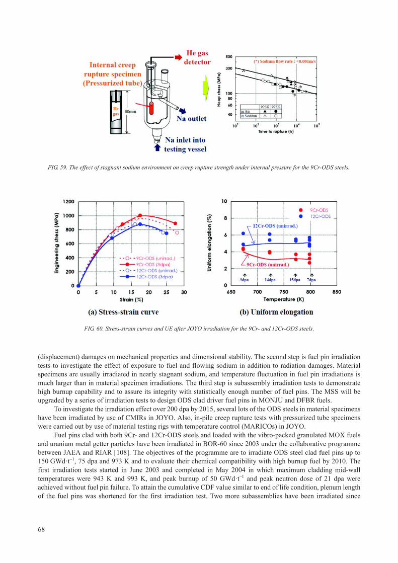
(displacement) damages on mechanical properties and dimensional stability. The second step is fuel pin irradiation tests to investigate the effect of exposure to fuel and flowing sodium in addition to radiation damages. Material specimens are usually irradiated in nearly stagnant sodium, and temperature fluctuation in fuel pin irradiations is much larger than in material specimen irradiations. The third step is subassembly irradiation tests to demonstrate high burnup capability and to assure its integrity with statistically enough number of fuel pins. The MSS will be upgraded by a series of irradiation tests to design ODS clad driver fuel pins in MONJU and DFBR fuels.
To investigate the irradiation effect over 200 dpa by 2015, several lots of the ODS steels in material specimens have been irradiated by use of CMIRs in JOYO. Also, in-pile creep rupture tests with pressurized tube specimens were carried out by use of material testing rigs with temperature control (MARICOs) in JOYO.
Fuel pins clad with both 9Cr- and 12Cr-ODS steels and loaded with the vibro-packed granulated MOX fuels and uranium metal getter particles have been irradiated in BOR-60 since 2003 under the collaborative programme between JAEA and RIAR [108]. The objectives of the programme are to irradiate ODS steel clad fuel pins up to 150 GWd·t–1, 75 dpa and 973 K and to evaluate their chemical compatibility with high burnup fuel by 2010. The first irradiation tests started in June 2003 and completed in May 2004 in which maximum cladding mid-wall temperatures were 943 K and 993 K, and peak burnup of 50 GWd·t–1 and peak neutron dose of 21 dpa were achieved without fuel pin failure. To attain the cumulative CDF value similar to end of life condition, plenum length of the fuel pins was shortened for the first irradiation test. Two more subassemblies have been irradiated since
FIG. 59. The effect of stagnant sodium environment on creep rupture strength under internal pressure for the 9Cr-ODS steels.
FIG. 60. Stress-strain curves and UE after JOYO irradiation for the 9Cr- and 12Cr-ODS steels.
68

August 2005; one targets 100 GWd·t–1 and 50 dpa by JFY2008 and the other 150 GWd·t–1 and 75 dpa by JFY2009. (The test is completed with the max. dose 51 dpa, see Section 3.7.4).
Six fuel pins clad with the 9Cr-ODS steel will be irradiated up to 180 GWd·t–1 and 210 dpa by 2015 in JOYO MK-III core after 2008. The irradiation test condition and schedule in JOYO are summarized in Fig. 60.
For joining a tube to end-plugs in fuel pin assembling, the JAEA has developed pressurized resistance welding (PRW) technology, which is based on electrical resistance heating across the interface under sufficient continuous contact force [109]. Instantaneous and forging process expels liquid weld and obtains metallurgical bonded weld with the original microstructure. The existing fusion welding methods such as TIG welding significantly degrades mechanical properties around the weld, because large size of blowholes and coarsened dispersoids will emerge. Electric current, voltage and contact force have been selected to weld reproducibly. For the welded specimens, tensile, burst and creep rupture tests were conducted to assure its integrity and quality. In addition, an ultrasonic inspection method has been developed to non-destructively examine the weld.
6.2.6. Current status and project schedule
6.2.6.1. Current status
Since 1987, the JAEA has been developing the ODS steels, and recently selected two promising candidates. One is martensitic 9Cr-ODS steel and the other is fully ferritic 12Cr-ODS steel. Alloying tungsten up to 2 mass percent offers solution hardening with little detrimental laves compound precipitations. Titanium and Y2O3 addition under controlled oxygen contamination enables to uniformly disperse a few to several nanometre size complex oxides and enhances dispersion strengthening effect.
PM and seamless precision tube production process are combined to manufacture the tubes. PM process controls oxide particle size distribution. Since anisotropic grain growth degrades high temperature strength against hoop stress, alpha to gamma phase transformation for the 9Cr-ODS steel and recrystallization for the 12Cr-ODS steel are applied to control grain morphology. Appropriately combining intermediate or final HT temperatures with cooling rates can either soften or harden matrix in Pilger cold-rolling process.
Mechanical properties of the tubes have been extensively tested in air and stagnant sodium environments to establish MSS for fuel pin mechanical design. Hundreds of specimens have been irradiated in JOYO to investigate
FIG. 61. Schedule of JOYO irradiation tests.
69

the effect of radiation damages on mechanical properties and dimensional stability. PIEs for tensile specimens exposed up to 15 dpa revealed that no effect on UE is observed and that there are slight increases in proof strength and UTS of both 9Cr- and 12Cr-ODS steels.
Both 9Cr- and 12Cr-ODS steel clad fuel pins with vibro-packed MOX fuel have been irradiated since 2003 under the collaborative programme between the JAEA and the RIAR in BOR-60. Pressurized resistance welding technology has been developed to join a tube to end-plugs.
6.2.6.2. Project schedule
In FS phase II, we prioritized that the 9Cr-ODS steel is the primary candidate and the 12Cr-ODS steel is the secondary, and scheduled long term R&D plan as shown in Fig. 62 [94].
Manufacturing process for mass production to supply annually 10 000 tubes for future SFR fuels will be developed only for the 9Cr-ODS steel by 2010, where scale-up from laboratory to engineering in mechanical alloying and hot-consolidation processes will be the most important issues.
MSS will be upgraded for both 9Cr- and 12Cr-ODS steels by a series of material specimen and fuel pin irradiation tests in BOR-60 and JOYO until 2015. Six fuel pins, which are clad with the 9Cr-ODS steel and loaded with annular MOX fuel pellets, will be irradiated to demonstrate high burnup capability in the JOYO after 2008; target dose is 210 dpa with peak burnup: 180 GWd·t–1 by 2015. The upgraded MSS will be applied to design ODS clad driver fuel pins in MONJU and DFBR fuels.
6.3. REPUBLIC OF KOREA
S.-H. Kim (KAERI)
In the Republic of Korea, R&D activities on a sodium cooled fast reactor (SFR) were initiated in 2007 and focused on metallic fuel and FM steel as fuel assembly structural materials. As cladding tubes, high performance 9Cr-2W steels (Korean alloy) capable of reaching 250 dpa at 650°C are being developed. The cladding tube will have an inner liner of V or Cr to minimize the chemical interaction with a metallic fuel.
FIG. 62. Project schedule.
70

Suitable coating techniques for these candidate barrier materials for the inner surface of a cladding are also being studied. Modified 9Cr-1Mo steels are being considered as wrapper materials in a SFR.
Figure 63 shows the draft road map for a SFR fuel cladding development. On the basis of a grade 92 (9Cr-0.5Mo-1.8W-VNb), new alloy designs and an evaluation of the out of pile performance of these new alloys are scheduled until 2011. Large scale manufacturing of the FM steel cladding tubes will be initiated in 2011, and in-pile tests of these cladding tubes will be finished by 2022. R&D activities on ODS-FM steel are expected to start in 2010, followed by the same progress of the FM steel development programme.
Ten kinds of batch 0 alloys were designed, and their nominal compositions are given in Table 13. These alloy designs were mainly focused on the effects of B, C, Nb and Ta on the mechanical properties of cladding tubes. The alloy ingots, with 30 kg scale each, were prepared by a vacuum induction melting process at a Korean steel company, POSCO. The steel ingots were hot-rolled to a 15 mm thickness after a preheating at 1150°C for 2 h, followed by a normalizing at 1050°C for 1 h and a tempering at 750°C for 2 h.
The tensile and creep test results at 650°C for the batch 0 alloys and the reference steels such as grade 92 and HT-9 are shown in Fig. 64. The results could be summarized in that some of the new alloys exhibited superior mechanical properties compared with the reference steels, and the additions of 0.17% B, 0.07% C, 0.13% Nb and 0.05% Nb-0.14% Ta led to enhanced tensile and creep properties.
TABLE 13. CHEMICAL COMPOSITIONS OF THE BATCH 0 ALLOYS
ID Nominal composition (wt%) Remark
B001 9Cr-2W00 Reference material
B002 9Cr-2W-0.008B Effect of B
B003 9Cr-2W-0.017B
B004 9Cr-2W-0.07C Effect of C
B005 9Cr-2W-0.05C
B006 9Cr-2W-V-0.13Nb Effect of Nb
B007 9Cr-2W-V-0.06Nb
B008 9Cr-2W-V-0.04Nb
B009 9Cr-2W-V-0.08Nb-0.08Ta Effect of Ta
B010 9Cr-2W-V-0.05Nb-0.14Ta
Develop. Key tech. Verification tech. Demonstration tech. Commercialization tech.
Develop. New FMS cladding
Verifi. of new FMS
Manufac. FM steel cladding & out-of-pile test
In-pile test of FM steel cladding
Commercialization of new FM steel
Basic study
Develop. of evaluation technologyfor out-of-pile performance
Cladding Manufac. Tech.
Develop. of evaluation technologyfor in-pile performance
Develop. ODS steel Manufac. ODS steel cladding & out-of-pile test
In-pile test ofODS steel cladding
Commercialization of ODS steel
FIG. 63. Draft road map for a SFR fuel cladding development in the Republic of Korea.
71

Based on these results of the batch 0 alloys, ten kinds of batch 1 alloys were designed (Table 14). These alloy designs were focused on, not only optimized concentrations of V, Nb and Ta, but also the effects of additional alloying elements such as Ti, Zr, Pd, Pt and Nd.
The tensile and creep test results at 650°C of the batch 1 alloys and the reference alloys are shown in Fig. 65. The B107 and B109 alloys were found to be superior in their tensile and creep properties. On the basis of these experimental results, batch 2 alloys were also designed, and their out of pile performances are being evaluated.
Figure 66 shows the schematic flow of the fabrication process for the FM steels in a form of a plate with a 1 mm thickness. The hot-rolled and normalized plates were tempered at 550°C and 750°C, respectively. The plate tempered at 750°C was cold-rolled to a 1 mm plate with a reduction ratio of 75%, followed by an annealing at 700°C for 30 min (Specimen ID: Ref.). The plate tempered at 550°C was cold-rolled to a 1 mm thickness, and then subjected to a HT at 750°C for 30 min (Specimen ID: CA1). Twice cold rolling was conducted with an intermediate HT at 750°C for 10 min after the first stage of a cold rolling (Specimen ID: CA2). Three cold rolling passes with intermediate HTs were also performed (Specimen ID: CA3).
Figure 67 shows images of extraction replicas for precipitates in these plates. M23C6 and MX precipitates were found in all specimens, and fine, uniform precipitates were observed in the CA3 specimen. These results closely correlated with the strain energy stored by a cold rolling.
The tensile test results at 650°C of these plates are shown in Fig. 68. The CA3 specimen was found to be superior in its tensile strengths, being mainly attributed to the finely distributed precipitates.
TABLE 14. CHEMICAL COMPOSITIONS OF THE BATCH 1 ALLOYS
ID Nominal composition (wt%) Remark
B101 9Cr-2W-V-Nb-Ta-B1 Reference material
B102 9Cr-2W-V-Nb-Ta-B2 Effects of V, Nb and Ta concentrations
B103 9Cr-2W-V-Nb-Ta-B3
B104 9Cr-2W-V-Nb-Ta-B4
B105 9Cr-2W-V-Nb-Ta-B5 Effects of C and N concentrations
B106 9Cr-2W-V-Nb-B-Ti Effect of Ti
B107 9Cr-2W-V-Nb-B-Zr Effect of Zr
B108 9Cr-2W-V-Nb-B-Pd Effect of Pd
B109 9Cr-2W-V-Nb-B-Pt Effect of Pt
B110 9Cr-2W-V-Nb-B-Nd Effect of Nd
B001 B002 B003 B004 B005 B006 B007 B008 B009 B010 Gr.92 HT-90
50
100
150
200
250
300
350
400
450
500
0
Tota
l Elo
ngat
ion,
%
Stre
ngth
, MPa
YS UTS TE YS(Ref.) UTS(Ref.) TE(Ref.)
10
20
30
40
50
60
100 1000 10000100
650oC
Stre
ss, M
Pa
Time to Rupture, h
HT9 T92 B001 B002 B003 B004 B005
(a) (b)
FIG. 64. (a) Tensile and (b) creep test results at 650°C for the batch 0 alloys and the reference steels of grade 92 and HT-9.
72

6.4. CHINA
C. Huang (CIAE)
In addition to a grade 92 FM alloy currently under development, China is proceeding to develop a 13Cr-ODS alloy. The flow sheet is shown in Fig. 69. Results of ion beam irradiation of ODS steels are given in References [110–112].
6.4.1. Mechanical properties and ion beam irradiation results of unirradiated 13Cr-ODS alloy
Several samples were prepared for different tests. The compositions of the sample are shown in Table 15. Tensile tests were conducted for the samples S1, S2, S4, T2, T5, T7, and T8, and creep tests were performed for the samples S2, K5, and K7. Ion beam irradiation tests were done for the samples S1, S2, T2 and T7 compared with austenitic steels.
B102 B103 B104 B105 B106 B107 B108 B109 B110 Gr.92 HT90
50
100
150
200
250
300
350
400
450
500
0
Tota
l Elo
ngat
ion,
%
Stre
ngth
, MPa
YS UTS TE YS(Ref.) UTS(Ref.) TE(Ref.)
10
20
30
40
50
60
100 1000100
Stre
ss, M
Pa
Time to Rupture, h
HT9 T92 B103 B104 B105 B106 B107 B108 B109 B110
650oC
(a) (b)
FIG. 65. (a) Tensile and (b) creep test results at 650°C of the batch 1 alloys and the reference steels of grade 92 and HT-9.
Hot rolling (4T)
Pre-heating(1150oC/2h)
Tempering (750oC/2h)
Tempering(550oC/2h)
VIM(Fe-9Cr-2W-0.2V-0.2Nb
0.5Mo-0.05C, 0.05N)
Normalizing (1050oC/1h)
IHT(750oC/10min)
CR (4 1T) 1CR (4 2.7T)
2CR (2 1T)
2-IHT (750oC/10min)
2CR (2.7 1.8T)
3CR (1.8 1T)
FHT (750oC/20min)
FHT(750oC/10min)
FHT (750oC/30min)
1-IHT (750oC/10min)
Ref.
ID : CA3
ID : CA1
ID : CA2
1CR (4 2T)CR (4 1T)
FHT (700oC/30min)
FIG. 66. Schematic of fabrication process for FM steels in plate form with of 1 mm thickness.
73

strength of S2 was thought to be attributed to the formation of χphase in the matrix caused by the high content of Ti. The Ion irradiation simulations indicated that ODS alloys are superior to austenitic alloys in the resistance to irradiation swelling and segregation.
FIG. 67. TEM images of the extraction replicas for the precipitates in the FM steels with 1 mm plates: (a) Ref., (b) CA1, (c) CA2 and (d) CA3.
0
20
40
60
80
100
0
100
200
300
400
500
Ref. CA3CA2CA1
Stre
ngth
, MP
a
Yield Tensile
Elo
ngat
ion,
%
Elongation
FIG. 68. Tensile test results at 650°C of the FM steels with a 1 mm thickness.
74

TABLE 15. COMPOSITION OF 13-CR ODS SAMPLES (WT%)
No. Cr Ti Mo W Y2O3 O N C
S1 12.94 3.47 1.50 — 0.38 * * *
S2 13.08 2.23 1.43 — 0.38 0.54 0.16 0.02
S4 12.98 1.06 0.92 — 0.38 * * *
T2 13.61 1.96 1.44 — 0.40 * * *
T5 13.70 1.27 0.60 — 0.39 * * *
T7 13.69 1.12 0.20 2.02 0.39 * * *
T8 13.62 0.70 0.07 2.32 0.37 * * *
K5 13.51 1.32 0.60 — 0.39 0.24 0.015 0.011
K7 13.44 1.14 0.19 2.11 0.39 0.24 0.022 0.007
Note: * not given.
Compacted by HIP
1100 oC, �30 mm Stick
Fe, Cr, W, Ti, Mo, Y2O3 etc.
Mechanical Alloyed by Ball
Cutting, Heat treatment, Mechanical test
FIG. 69. Simple flow sheet of production of 13Cr-ODS alloys.
FIG. 70. The creep curves of S2, K5, and K7 samples.
75

7. CONCLUSIONS
The major issue driving materials research for fast reactors remains the necessity to roughly double the currently achievable burnups of 10–12% heavy atoms.
Attaining higher burnups requires significantly improved cladding materials to resist void swelling, excessive embrittlement and loss of high temperature strength.
The potential for further improvement of austenitic steels to resist swelling beyond 100–150 dpa appears to be very small.
The use of ferritic and ferritic-martensitic steels appears to offer the possibility to extend the low-swelling regime to perhaps 200–250 dpa but its low strength at high temperatures affects fuel operational characteristics, and requires special design measures to reduce the internal pressure on the cladding arising first from fission gas but eventually from fuel-clad interaction.
The most promising approach is to develop ODS variants of ferritic and FM steels that will have higher thermal stability and hopefully lower swelling than their non-ODS counterparts. The latter benefit of high-dose swelling reduction has yet to be experimentally demonstrated.
Since there is no prospect in the foreseeable future of reaching neutron-induced dpa levels in excess of 150–200 dpa, the materials community have to develop ion simulation procedures that are capable of reaching such dpa levels, recognizing that such capability has the potential to address the potential of reduced swelling in ODS alloys, but is probably not suited to address concerns about irradiation and thermal creep, as well as embrittlement. Such accelerator simulation procedures should be combined with theoretical modelling with the aim of adequate interpretation of radiation effects got in different (ion versus neutron) irradiation environments.
TABLE 16. TENSILE PROPERTIES AND RUPTURE LIFE STRESS AT 650°C
No. σb, MPa σ0.2, MPa δ, % σb/100, MPa
S1 520 381 29.0
S2 468 428 35.5 >260
S4 408 365 21.0 >270
T2 598 542 23.0
T5 542 490 27.0 >340
T7 542 515 23.0 >340
T8 572 548 25.0 >420
76

REFERENCES
[1] GREENWOOD, L.R., Neutron interactions and atomic recoil spectra, J. Nucl. Mater. 216 (1994) 29–44. [2] GARNER, F.A., GREENWOOD, L.R., Survey of recent developments concerning the understanding of radiation effects on
stainless steels in the LWR power industry, Proceedings of 11th International Conference on Environmental Degradation of Materials in Nuclear Power Systems — Water Reactors (2003) 887–909.
[3] GARNER, F.A., Irradiation performance of cladding and structural steels in liquid metal reactors, Nuclear Materials: Part 1, Materials Science and Technology: A comprehensive Treatment, FROST, B.R.T., (Ed.), VCH Publishers (1993) 419–543.
[4] POROLLO, S.I., VOROBJEV, A.N., KONOBEEV, YU.V., DVORIASHIN, A.M., KRIGAN, V.M., BUDYLKIN, N.I., MIRONOVA, E.G., GARNER, F.A., Swelling and void-induced embrittlement of austenitic stainless steel irradiated to 73–82 dpa at 335–365°C, J. Nucl. Mater. 258–263 (2) (1998) 1613–1617.
[5] POROLLO, S.I., SHULEPIN, S.V., KONOBEEV, YU.V., GARNER, F.A., Influence of silicon on swelling and microstructure in Russian austenitic stainless steel EI-847 irradiated to high neutron doses, J. Nucl. Mater. 378 (1) (2008)17–24.
[6] GARNER, F.A., PORTER, D.L., MAKENAS, B.J., A third stage of irradiation creep involving its cessation at high neutron exposures, J. Nucl. Mater. 148 (3) (1987) 279–287.
[7] TOLOCZKO, M.B., GARNER, F.A., Reanalysis of swelling and irradiation creep data on 316 type stainless steels irradiated in the FFTF and Phénix fast reactors, Proceedings of Effects of Radiation on Materials: 19th International Symposium, (HAMILTON, M.L., KUMAR, A.S., ROSINSKI, S.T., GROSSBECK, M.L. (Eds)), American Society for Testing and Materials, ASTM STP 1366 (2000) 655–666.
[8] TOLOCZKO, M.B., GARNER, F.A., Effects of Radiation on Materials: 18th International Symposium, (NANSTAD, R.K., HAMILTON, M.L., GARNER, F.A., KUMAR, A.S. (Eds)), American Society of Testing and Materials, ASTM STP 1325 (1999) 765–779.
[9] HAMILTON, M.L., HUANG, F.H., YANG, W.J.S., GARNER, F.A., Proceedings of Effects of Radiation on Materials: Thirteenth International Symposium (Part II) Influence of Radiation on Material Properties, (GARNER, F.A., IGATA, N., HENAGER, C.H., Jr., (Eds)), American Society for Testing and Materials, ASTM STP 956, Philadelphia, PA (1987) 245–270.
[10] FISSOLO, A., CAUVIN, R., HUGOT, J.P., LEVY, V., Influence of swelling on irradiated Ti modified 316 embrittlement, 11th
International Symposium, Effects of Radiation on Materials, American Society for Testing and Materials, ASTM STP 782, (GARNER, F.A ., PERRIN, J.S. (Eds)), Philadelphia (1982) 700–713.
[11] POROLLO, S.I., KONOBEEV, YU.V., SHULEPIN., S.V., Analysis of the behaviour of 0Kh16N15M3BR steel BN-600 fuel-element cladding at high burnup, Journal Atomnaya Energiya, 106 (4) (2009) 188–195 (In Russian).
[12] NEUSTROEV, V.S., OSTROVSKY, Z.E., TEYKOVTSEV, A.A., SHAMARDIN, V.K., YAKOLEV, V.V., Experimental investigations of destruction of irradiated hexahedral FA wrappers of the BOR-60 reactor, Proceedings of the First Inter-industry Conference on Reactor Material Science, Vol. 2, Part 2, Dimitrovgrad (1998) 42–66 (in Russian).
[13] GARNER, F.A., EDWARDS, D.J., BRUEMMER, S.M., POROLLO, S.I., KONOBEEV, YU.V., NEUSTROEV, V.S., SHAMARDIN, K., KOZLOV, A.V., Contribution of Materials Investigation to the Resolution of Problems Encountered in Pressurized Water Reactors, Proceedings of Fontevraud 5 (2002) Paper 22.
[14] DUBUISSON, P.H., ‘Core structural materials — feedback experience from PHÉNIX’, Design, Manufacturing and Irradiation Behaviour of Fast Reactor Fuels (Proc. Mtg. Obninsk, 2011), IAEA-TECDOC-1689, Vienna (in preparation).
[15] CHEON, J.-S., et al., U-Zr SFR fuel irradiation test in HANARO; Design, Manufacturing and Irradiation Behaviour of Fast Reactor Fuels (Proc. Mtg. Obninsk, 2011), IAEA-TECDOC-1689, Vienna (in preparation).
[16] CHELLAPANDI, P., PUTHIYAVINAYAGAM, P., JEYAKUMAR, T., CHETAL, S.C., RAJ, B., ‘Approach to the design and development of high burnup fuels for sodium cooled fast reactors’, Design, Manufacturing and Irradiation Behaviour of Fast Reactor Fuels (Proc. Mtg. Obninsk, 2011), IAEA-TECDOC-1689, Vienna (in preparation).
[17] MAEDA, S., ‘Status of the development of fast breeder reactor fuels in FaCT Project’, Design, Manufacturing and Irradiation Behaviour of Fast Reactor Fuels (Proc. Mtg. Obninsk, 2011), IAEA-TECDOC-1689, Vienna (in preparation).
[18] NAKAE, N., BABA, T., KAMIMURA, K., Basis of technical standard on fuel for sodium-cooled fast breeder reactor, J. Nucl. Sci. and Technol. 48 (4) (2011) 524–531.
[19] INTERNATIONAL ATOMIC ENERGY AGNECY, Specialists' Meeting on Predictions and Experience of Core Distortion Behaviour, Working Material of the Technical Working Group on Fast Reactors, IWGFR-54, Wilmslow (1984).
[20] CAWTHORNE, C., FULTON, F.J., Voids in irradiated stainless steel, Nature 216 (1967) 575–576.[21] MOSEDALE, D., LEWTHWAITE, G.W., LEET, G.O., SLOSS, W., Irradiation creep in the Dounreay fast reactor, Nature 244
(1969) 1301.[22] WALTERS, L.C., WALTER, C.M., Observations of dilation and bowing in Experimental Breeder Reactor II ducts and cladding,
Nuclear Technology 46 (1) (1979) 134.[23] HOFMAN, G.L., Irradiation behaviour of the experimental MK-II EBR-II driver fuel, Nucl. Tech. 47 (1980) 7–22.[24] JOHNSTON, W.G., ROSOLOWSKI, J.H., TURKALO, A.M., LAURITZEN, T., An experimental survey of swelling in
commercial Fe-Cr-Ni alloys bombarded with 5 MeV Ni ions, J. Nucl. Mater. 54 (1974) 24–40.[25] BATES, J.F., POWELL, R.W., Irradiation induced swelling in commercial alloys, J. Nucl. Mater. 102 (1981) 200–213.
77
[26] GARNER, F.A., Recent insights on the swelling and creep of irradiated austenitic alloys, J. Nucl. Mater 122–123 (1984) 459–471.
[27] GARNER, F.A., BRAGER, H.R., Swelling of austenitic iron-nickel-chromium ternary alloys during fast neutron irradiation, Effects of Radiation on Materials: Twelfth International Symposium, ASTM STP 870, (GARNER, F.A., PERRIN, J.S. (Eds)), Philadelphia, PA (1985) 187–201.
[28] GARNER, F.A., KUMAR, A.S., The influence of both major and minor element composition on void swelling in austenitic steels, Effects of Radiation on Materials: Thirteenth International Symposium (Part 1) Radiation induced Changes in Microstructure, ASTM STP 955, (GARNER, F.A., PACKAN, N.H., KUMAR, A.S. (Eds)), Philadelphia, PA (1987) 289–314.
[29] GARNER, F.A., GELLES, D.S., Neutron-induced swelling of commercial alloys at very high exposures, Symposium on Effects of Radiation on Materials: 14th International Symposium, (PACKAN, N.H., STOLLER, R.E., KUMAR, A.S. (Eds)), American Society for Testing and Materials, ASTM STP 1046, Vol. II, Philadelphia, PA (1990) 673–683.
[30] GARNER, F.A., Optimizing Materials for Nuclear Applications, (GARNER, F.A., GELLES, D.S., WIFFEN, F.W. (Eds)), TMS-AIME, Warrendale, PA (1985) 111–139.
[31] GARNER, F.A., BATES, J.F., MITCHELL, M.A., The strong influence of temper annealing conditions on the neutron-induced swelling of cold-worked austenitic steels, J. of Nucl. Mater. 189 (1992) 201–209.
[32] APPLEBY, W.K., BLOOM, E.E., FLINN, J.E., GARNER, F.A., Swelling in neutron-irradiated 300-series stainless steels, International Conference on Radiation Effects in Breeder Reactor Materials, TMS-AIME, Scottsdale, AZ (1977) 509–527.
[33] BUSBOOM, H.J., MCCLELLAN, G.C., BELL, W.L., APPLEBY, W.K., Swelling of types 304 and 316 stainless steel irradiated to 8 × 10²² n·cm-2, General Electric Company Report GEAP-14062, Sunnyvail, CA (1975).
[34] SERAN, J.L., LEVY, V., DUBUISSON, P., GILBON, D., MALLIARD, A., FISSOLO, A., TOURON, H., CAUVIN, R., CHALONY, A., LE BOULBIN, E., Behaviour under neutron irradiation of the 15-15Ti and EM10 steels used as standard materials of the Phénix fuel subassembly, Effects of Radiation on Materials: 15th International Symposium, (STOLLER, R.E., KUMAR, A.S., GELLES, D.S. (Eds)), American Society for Testing and Materials, ASTM STP 1125, Philadelphia (1992) 1209.
[35] MAZIASZ, P.J., MCHARGUE, C.J., Microstructural evolution in annealed austenitic steels during neutron irradiation, Int. Mater. Rev. 32 (4) (1987) 190–219.
[36] OKITA, T., SATO, T., SEKIMURA, N., GARNER, F.A., GREENWOOD, L.R., J. Nucl. Mater. 307–311 (2002) 322–326.[37] GARNER, F.A., BLACK, C.A., EDWARDS, D.J., Factors which control the swelling of Fe-Cr-Ni ternary austenitic alloys, J. of
Nucl. Mater. 245 (1997) 124–130.[38] ESMAILZADEH, B., KUMAR, A.S., GARNER, F.A., The influence of silicon on void nucleation in irradiated alloys, J. of
Nucl. Mater. 133–134 (1985) 590–593.[39] COGHLAN, W.A., GARNER, F.A., Effect of nickel content on the minimum critical void radius in ternary austenitic alloys,
Effects of Radiation on Materials: Thirteenth International Symposium (Part 1) Radiation induced Changes in Microstructure, ASTM STP 955, (GARNER, F.A., PACKAN, N.H., KUMAR, A.S. (Eds)), ASTM, Philadelphia, PA (1987) 315–327.
[40] RUSSELL, K.C., Phase stability under irradiation, Prog. Mater. Sci. 28 (1984) 229–434.[41] MAZIASZ, P.J., Overview of microstructural evolution in neutron-irradiated austenitic stainless steels, J. Nucl. Mater. 205
(1993) 118–145.[42] LEE, E.H., MANSUR, L.K., Relationships between phase stability and void swelling in Fe-Cr-Ni alloys during irradiation,
Metall. Trans. 23A (1992) 1977–1986.[43] SEKIMURA, N., OKITA, T., GARNER, F.A., Influence of carbon addition on neutron-induced void swelling of
Fe–15Cr–16Ni–0.25Ti model alloy, J. Nucl. Mater. 367–370 (2007) 897–903.[44] HERSCHBACH, K., SCHNEIDER, W., EHRLICH, K., Effects of minor alloying elements upon swelling and in-pile creep in
model plain Fe-15Cr-15Ni stainless steels and in commercial DIN 1.4970 alloys, J. Nucl. Mater. 203 (1993) 233–248. [45] TATEISHI, Y., Development of Long Life FBR Fuels with Particular Emphasis on Cladding Material Improvement and Fuel
Fabrication, J. Nucl. Sci. Tech. 26 (1) (1989) 132.[46] BOULANGER, J., LE NAOUR, L., LEVY, V., Effect of dose rate on the microstructure of cold-worked 316 stainless steel,
Proc. Conference on Dimensional Stability and Mechanical Properties of Irradiated Metals and Alloys, Vol. 1, Brighton, British Nuclear Energy Societym (1983) 1–4.
[47] BUDYLKIN, N.I., BULANOVA, T.M., MIRONOVA, E.G., MITROFANOVA, N.M., POROLLO, S.I., CHERNOV, V.M., SHAMARDIN, V.K., GARNER, F.A., The strong influence of displacement rate on void swelling in variants of Fe–16Cr–15Ni–3Mo austenitic stainless steel irradiated in BN-350 and BOR-60, J. Nucl. Mater. 329–333 (2004) 621–624.
[48] THE METALLURGICAL SOCIETY OF AIME, Proceedings of Topical Conference on Ferritic Alloys for use in Nuclear Energy Technologies, TMS-AIME, (DAVIS, J.W., MICHEL, D.J. (Eds)), Snowbird, Utah (1983).
[49] SENCER, B.H., GARNER, F.A., Compositional and temperature dependence of void swelling in model Fe–Cr base alloys irradiated in the EBR-II fast reactor, J. Nucl. Mater. 283–287 (2000) 164–168.
[50] GARNER, F.A., TOLOCZKO, M.B., SENCER, B.H., Comparison of swelling and irradiation creep behaviour of fcc-austenitic and bcc-ferritic-martensitic alloys at high neutron exposure, J. Nucl. Mater. 276 (2000) 123.
[51] GARNER, F.A., GELLES, D.S., GREENWOOD, L.R., OKITA, T., SEKIMURA, N., WOLFER, W.G., Synergistic influence of displacement rate and helium/dpa ratio on swelling of Fe–(9, 12)Cr binary alloys in FFTF at ~400°C, J. Nucl. Mater. 329–333(2004) 1008–1012.
78

[52] TOLOCZKO, M.B., GARNER, F.A., EIHOLZER, C.R., Irradiation creep and swelling of the US fusion heats of HT9 and 9Cr-1Mo to 208 dpa at ~400°C, J. of Nucl. Mater. 212–215 (1994) 604-607.
[53] DVORIASHIN, A.M., POROLLO, S.I., KONOBEEV, Yu.V., GARNER, F.A., Influence of high dose neutron irradiation on microstructure of EP-450 ferritic–martensitic steel irradiated in three Russian fast reactors, J. Nucl. Mater. 329–333 (2004) 319–323.
[54] BROWN, C., LEVY, V., SERAN, J.L., EHRLICH, K., ROGER, R.J.C., BERGMANN, H., Proc. Fast Reactors and Related Fuel Cycles, FR-91, Atomic Energy Society, Tokyo 1 (1991) 75.
[55] B. H. Sencer, J. R. Kennedy, J. I. Cole, S. A. Maloy and F. A. Garner, Microstructural analysis of an HT9 fuel assembly duct irradiated in FFTF to 155 dpa at 443°C, J. Nucl. Mater. 393 (2009) 235–241.
[56] GOLOVANOV, V.N., SHAMARDIN, V.K., PROCHOROV, V.V., J. Atomnaya Energiya 91 (5) (2001) 389–400 (In Russian).[57] TSELISHCHEV, A.V., BUDANOV, Y.P., MITROFANOVA, N.M., et al., ‘Development of structural steels for fuel pins and fuel
assemblies of sodium cooled fast reactors’, Design, Manufacturing and Irradiation Behaviour of Fast Reactor Fuels (Proc. Mtg. Obninsk, 2011), IAEA-TECDOC-1689, Vienna (in preparation).
[58] POVSTYANKO, A.V., FEDOSEEV, A.Ye., MAKAROV, O.Yu., PROKHOROV, V.I., A study of four experimental fuel subassemblies using EP-450 FM pin claddings and hexagonal ducts after irradiation to 108–163 dpa in the BOR-60 reactor, Proc. of 2010 ANS Winter Meeting, Las Vegas, NV (2010).
[59] ANDERKO, K., DAVID, E., OHLY, W., SCHIRRA, M., WASSELEW, C., Ferritic alloys for use in nuclear energy, Proc. Topical Conference on Ferritic Alloys for Use in Nuclear Energy Technologies, Snowbird, UT (1983) 299–306.
[60] DUPOUY, J.M., CARTERET, Y., AUBERT, H., BOUTARD, J.L., EM 12 a possible fast reactor core material, Proc. Topical Conference on Ferritic Alloys for Use in Nuclear Energy Technologies, Snowbird, UT (1983) 125–128.
[61] LOVELL, A.J., WILSON, D.R., LEIBNITZ, D.F., SUTHERLAND, W.H., Predicted performance of the ferritic-martensitic alloy HT9 cladding in an FFTF test of advanced oxide fuel, Proc. Topical Conference on Ferritic Alloys for Use in Nuclear Energy Technologies, Snowbird, UT (1983) 135–138.
[62] KHABAROV, V.S., DVORIASHIN, A.M., POROLLO., S.I., The performance of type EP-450 ferritic-martnesitic steel under neutron irradiation at low temperatures, Proc. of IAEA TCM on Influence of High Dose Irradiation on Core Structural and Fuel Materials in Advanced Reactor, International Atomic Energy Agency, IAEA-TECDOC-1039, Obninsk, Russian Federation (1998) 139–144.
[63] SERAN, J.L., LEVY, V., DUBUISSON, P., GILBON, D., MAILLARD, A., FISSOLO, A., TOURON, H., CAUVIN, R., CHALONY, A., LE BOULBIN, E., Behaviour under neutron irradiation of the 15-15Ti and EM10 steels used as standard materials of the Phénix fuel subassembly, Effects of Radiation on Materials: 15th International Symposium, ASTM STP 1125 (STOLLER, R.E., KUMAR, A.S., GELLES, D.S. (Eds)) (1992). 1209–1233.
[64] DUBUISSON, P., et al., ODS ferritic-martensitic alloys for sodium fast reactor fuel pin cladding, DIANA I Workshop Dispersion Strengthened Steels For Advanced Nuclear Applications, Aussois, J. Nucl. Mat. 428 (1–3) (2012) 6–12.
[65] MAEDA, S., ‘Status of the development of fast breeder reactor fuels in FaCT project’, Design, Manufacturing and Irradiation Behaviour of Fast Reactor Fuels, (Proc. Mtg. Obninsk, 2011), IAEA-TECDOC-1689, Vienna (in preparation).
[66] HAMILTON, M.L., GELLES, D.S., LOBSINGER, R.B., JOHNSON, G.D., BROWN, W.F., PAXTON, M.M., PUIGH, A.J., EIHOLZER, C.R., MARTINEZ, C., BLOTTER, M.A., Fabrication technological development of the oxide dispersion strengthened alloy MA957 for fast reactor applications, Pacific Northwest National Laboratory Report PNNL-13168, Richland, WA (2000).
[67] TOLOCZKO, M.B., GELLES, D.S., GARNER, F.A., KURTZ, R.J., ABE, K., Irradiation creep and swelling from 400–600°C of the oxide dispersion strengthened ferritic alloy MA957, J. Nucl. Mater. 329-333 (2004) 352–355.
[68] ODETTE, G.R., ALINGER, M.J., WIRTH, B.D., Recent developments in irradiation-resistant steels, Annual Review of Materials Research 38 (2008) 471–503.
[69] MATHEW, M.D., PANIGRAHI, B., VENUGOPAL, S., BHADURI, A.K., Development of modified alloy D9 SS for PFBR fuel subassembly, Indira Gandhi Centre for Atomic Research, IGCAR/PFBR/MTG/2002/002, Kalpakkam (2002).
[70] SHANKAR, V., Role of Compositional Factors in Hot Cracking of Austenitic Stainless Steel Weldments, Ph.D. Thesis, Indian Institute of Technology, Madras (2000).
[71] KUJANPÄÄ, V., SUUTALA, N., TAKALO, T., MOISIO, T., Correlation between solidification cracking and microstructure in austenitic-ferritic stainless steel, Welding Research International 9 (1979) 55–76.
[72] PICKER, C., The fracture toughness of type 316 steel and weld metal, International Working Group on Fast Reactors’ Meeting on Mechanical Properties of Structural Materials Including Environmental Effects, IAEA, Chester (1983) 1019.
[73] KANI, Y., SAGAYAMA, Y., Proceedings of a Symposium: Energy and the Environment — The Role of Nuclear Power, (LEE, J.C. (Ed.)), DEStech Publications, University of Michigan, Michigan (2002) 139.
[74] RAJENDRAN PILLAI, S., MATHEWS, C.K., Carbon potential and carbide equilibrium in 18/8 austenitic steels, J. Nucl. Mater. 150 (1987) 31–41.
[75] SRIDHARAN, R., KRISHNANMURTHY, K., MATHEWS, C.K., Thermodynamic properties of ternary oxides of alkali metals from oxygen potential measurements, J. Nucl. Mater. 167 (1989) 265.
[76] BORGSTEDT, H.U., MATHEWS, C.K., Applied Chemistry of Alkali Metals, Plenum Press, New York (1987).[77] THORLEY, A.W., Corrosion and mass transfer behaviour of steel materials in liquid sodium, 3rd Int. Conference on Liquid
Metal Engineering and Technology, BNES, Oxford, Vol. 3 (1984) 31–41.
79

[78] MATHEWS, C.K., Thermochemistry of fuel-clad and clad-coolant interactions of fast breeder reactors, Pure & Appl. Chem. 67(6) (1995) 1011–1018.
[79] BORGSTEDT, H.U., Corrosion and mass transfer in fast sodium cooled reactors, Rev. Coating and Corros. 2 (1977) 121. [80] BORGSTEDT, H.U., MATHEWS, C.K., Applied Chemistry of Alkali Metals, Plenum Press, New York (1987). [81] SRIDHARAN, R., KRISHNANMURTHY, K., MATHEWS, C.K., Thermodynamic properties of ternary oxides of alkali metals
from oxygen potential measurements, J. Nucl. Mater. 167 (1989) 265. [82] CHARLES, R.G., Differential thermal analysis as a means for studying chemical reactions in liquid sodium, Trans. Am. Nucl.
Soc. 19 (1974) 107. [83] SRIDHARAN, R., GNANASEKARAN, T., MATHEWS, C.K., Phase-equilibrium studies in the Na-Fe-O system, J. Alloys and
Comp. 191 (1) (1973) 9–13. [84] BHAT, N.P., BORGSTEDT, H.U., Thermodynamic stability of Na4FeO3 and threshold oxygen levels in sodium for the
formation of this compound on AISI 316 steel surfaces, J. Nucl. Mater. 158 (1988) 7. [85] KOLSTER, B.W., Mechanism of Fe and Cr transport by liquid sodium in non-isothermal loop systems, J. Nucl .Mater. 55
(1975) 155. [86] YOSHIDA, E., KATO, S., Sodium compatibility of ODS steel at elevated temperature, J. Nucl. Mater. 329–333 (2004)
1393–1397. [87] TAKAHASHI, M., IGASHIRA, M., OBARA, T., SEKIMOTO, H., KIKUCHI, K., AOTO, K., KITANO, T., Studies on
materials for heavy-liquid-metal cooled reactors in Japan, Proceedings of 10th International Conference on Nuclear Engineering (ICONE10) Arlington, VA (2002) ICONE10-22166.
[88] ZRODNIKOV, A.V., TOSHINSKY, G.I., KOMLEV, O.G., STEPANOV, V.S., KLIMOV, N.N., KUDRYAVTSEVA, A.V., PETROCHENKO, V.S., SVBR-100 module-type fast reactor of the IV generation for regional power industry, Proceedings of Int. Conference on Fast Reactors and Related Fuel Cycles: Challenges and Opportunities (FR09), IAEA, Kyoto (2009) Paper IAEA-CN-176/01-09, 93–95.
[89] KAMATA, K., KITANO, T., ONO, H., ONO, M., Studies of corrosion resistance of Japanese steels in liquid lead-bismuth,Proceedings of 11th International Conference on Nuclear Engineering (ICONE12), Tokyo (2003) ICONE11-36204.
[90] KONDO, M., TAKAHASHI, M., SUZUKI, T., ISHIKAWA, K., HATA, K., QIU, S., SEKIMOTO, H., Metallurgical study on erosion and corrosion behaviours of steels exposed to liquid lead–bismuth flow, J. Nucl. Mater. 343 (2005) 349–359.
[91] RUSANOV, A.E., POPOV, V.V., KURINA, I.S., BIRZHEVOY, G.A., PEVCHIKH, Yu.M., Materials testing aspects of fuel elements development for lead-bismuth cooled fast reactor SVBR-100, Proceedings of Int. Conference on Fast Reactors and Related Fuel Cycles: Challenges and Opportunities (FR09), IAEA, Kyoto (2009) Paper IAEA-CN-176/04-21P, 421–427.
[92] Japan Atomic Energy Agency, Feasibility Study on Commercialized Fast Reactor Cycle Systems Technical Study Report of Phase II –(1) Fast Reactor Plant Systems-, JAEA Research 2006-042 (2006).
[93] KAITO, T., UKAI, S., OHTSUKA, S., NARITA, T., Development of ODS ferritic steel cladding for the advanced fast reactor fuels, GLOBAL2005, Tsukuba (2005) 169.
[94] KAITO, T., OHTSUKA, S., INOUE, M., Advanced nuclear fuel cycles and systems, GLOBAL2007, Idaho (2007) 37. [95] TATEISHI, Y., YUHARA, S., SHIBAHARA, I., ITO, M., NOMURA, S., SATO, Y., YOSHIDA, E., SHIKAKURA, S.,
Development of modified SUS 316 stainless steel as core material for fast breeder reactors, Journal of the Atomic Energy Society Japan, 30 (1988) 1005 (in Japanese).
[96] SHIKAKURA, S., NOMURA, S., UKAI, S., SESHIMO, I., KANO, Y., KUWAJIMA, Y., ITO, T., TSUTAKI, K., FUJITA, T., Development of high-strength ferritic-martensitic steel for FBR core materials, Journal of the Atomic Energy Society Japan, 33(12) (1991) 1157 (in Japanese).
[97] UKAI, S., MIZUTA, S., FUJIWARA, M., OKUDA, T., KOBAYASHI, T., Characterization of high temperature creep properties in recrystallized 12Cr–ODS ferritic steel claddings, J. Nucl. Sci. Technol., 39, Issue 7 (2002) 778–788.
[98] UKAI, S., KAITO, T., OHTSUKA, S., NARITA, T., FUJIWARA, M., KOBAYASHI, T., Production and properties of nano-scale 9Cr-ODS martensitic steel claddings, ISIJ International, 43, Issue 12 (2003) 2038–2045.
[99] OHTSUKA, S., UKAI, S., FUJIWARA, M., KAITO, T., NARITA, T., Improvement of 9Cr-ODS martensitic steel properties by controlling excess oxygen and titanium contents, J. Nucl. Mater., 329–333 (2004) 372–376.
[100] OHTSUKA, S., UKAI, S., SAKASEGAWA, H., FUJIWARA, M., KAITO, T., NARITA, T., Improvement of creep strength of 9Cr-ODS martensitic steel by controlling excess oxygen and titanium concentrations, Mater. Trans., 46, Issue 3 (2005) 487–492.
[101] OHTSUKA, S., UKAI, S., FUJIWARA, M., KAITO, T., NARITA, T., Nano-structure control in ODS martensitic steels by means of selecting titanium and oxygen contents, J. Phys. Chem. Solids., 66 (2005) 571–575.
[102] UKAI, S., KAITO, T., OHTSUKA, S., NARITA, T., SAKASEGAWA, H., Development of optimized martensitic 9Cr-ODS steel cladding, Transactions of the 2006 ANS Annual Meeting, Vol. 94, Reno (2006) 786–787.
[103] OHTSUKA, S., UKAI, S., SAKASEGAWA, H., FUJIWARA, M., KAITO, T., NARITA, T., Nano-mesoscopic structural characterization of 9Cr-ODS martensitic steel for improving creep strength, J. Nucl. Mater., 367–370 (2007) 160–165.
[104] NARITA, T., UKAI, S., KAITO, T., OHTSUKA, S., KOBAYASHI, T., Development of two-step softening heat treatment for manufacturing 12Cr–ODS ferritic steel tubes, J. Nucl. Sci. Technol., 41, Issue 10 (2004) 1008–1012.
[105] YOSHIDA, E., KATO, S., Sodium compatibility of ODS steel at elevated temperature, J. Nucl. Mater., 329–333 (2004) 1393–1397.
80

[106] YAMASHITA, S., AKASAKA, N., OHNUKI, S., Nano-oxide particle stability of 9–12Cr grain morphology modified ODS steels under neutron irradiation, J. Nucl. Mater., 329–333 (2004) 377–381.
[107] YOSHITAKE, T., ABE, Y., AKASAKA, N., OHTSUKA, S., UKAI, S., KIMURA, A., Ring-tensile properties of irradiated oxide dispersion strengthened ferritic-martensitic steel claddings, J. Nucl. Mater., 329–333 (2004) 342–346.
[108] UKAI, S., KAITO, T., SEKI, M., MAYORSHIN, A.A., SHISHALOV, O.V., Oxide dispersion strengthened (ODS) fuel pin fabrication for BOR-60 irradiation test, J. Nucl. Sci. Technol., 42, Issue 1 (2005) 109–122.
[109] SEKI, M., HIRAKO, K., KONO, S., KIHARA, Y., KAITO, T., UKAI, S., Pressurized resistance welding technology development in 9Cr-ODS martensitic steels, J. Nucl. Mater., 329–333 (2004) 1534–1538.
[110] TIAN, Y., PAN, Q., LIU, G., SHAN, B., YANG, F., Effects of Ti on Strengthening of ODS Ferritic Alloy for Advanced FBR Cladding Application, Acta Metallurgical Sinica, 34 (1998) 1217–1222 (in Chinese).
[111] TIAN, Y., LIU, G., SHAN, B., Creep properties of ODS ferritic alloys for FBR cladding application, powder metallurgical technology, 19 (2001) 16–19 (in Chinese).
[112] SUN, J., CHEN, C., ZHANG, X., TIAN, Y., SHANG, B., PAN, Q., Property of resistance to irradiation damage of ODS ferritic alloys, Acta Metallurgical Sinica, 34 (1998) 1210–1216 (in Chinese).
81

.

ABBREVIATIONS
AIM air induction melting
AOD argon oxygen decarburization
CDF creep-rupture damage factor
CEFR China Experimental Fast Reactor
CMIR core material irradiation rig
CW cold worked
DBTT ductile to brittle transition temperature
DMM dynamic materials model
EAF electric arc furnace
EBR Experimental Breeder Reactor
ESR electro slag refining
FBTR Fast Breeder Test Reactor
FM ferritic-martensitic
GIF Generation IV International Forum
GNEP Global Nuclear Energy Partnership
HT heat treatment
INCO International Nickel Company
INPRO International Project on Innovative Reactors and Fuel Cycles
JSFR Japanese Sodium Fast Reactor
LBC lead-bismuth coolant
LMC liquid metal corrosion
LMFR liquid metal cooled fast reactor
MARICO material testing rigs with temperature control
MFA material science fuel assembly
MOX mixed uranium plutonium oxide
83

MSS material strength standard
ODS oxide dispersion strengthened
PFBR Prototype Fast Breeder Reactor
PH precipitation-hardened
PIE post-irradiation examination
PM powder metallurgy
SFR sodium cooled fast neutron reactor
UE uniform elongation
UTS ultimate tensile strength
VAR vacuum arc re-melting
VIM vacuum induction melting
VIR vacuum induction refining
VOD vacuum oxygen decarburization
84

CONTRIBUTORS TO DRAFTING AND REVIEW
Aqrawi, A. International Atomic Energy Agency
Baek, J.-B. Korea Atomic Energy Research Institute, Republic of Korea
Bhutt, R.B. Bhabha Atomic Research Centre, India
Chetal, S.C. Indira Gandhi Centre for Atomic Research, India
Dubuisson, P. Commissariat à l'Energie Atomique, France
Ganguly, C. International Atomic Energy Agency
Garner, F.A. Pacific Northwest National Laboratory, USA
Huang, C. China Institute of Atomic Energy, China
Inoue, M. Japan Atomic Energy Agency, Japan
Inozemtsev, V. International Atomic Energy Agency
Jayaraj, R.N. Nuclear Fuel Complex, India
Kapoor, K. Nuclear Fuel Complex, India
Kasiviswanathan, K.V. Indira Gandhi Centre for Atomic Research, India
Kim, H.-K. Korea Atomic Energy Research Institute, Republic of Korea
Kim, J.-H. Korea Atomic Energy Research Institute, Republic of Korea
Kim, M.-R. Korea Atomic Energy Research Institute, Republic of Korea
Kim, S.H. Korea Atomic Energy Research Institute, Republic of Korea
Kim, T.-K. Korea Atomic Energy Research Institute, Republic of Korea
Kozlov, A. Institute of Numerical Mathematics, Russian Federation
Kutty, T.R.G. Bhabha Atomic Research Centre, India
Lakshminarayana, B. Nuclear Fuel Complex, India
Lee, J.W. Korea Atomic Energy Research Institute, Republic of Korea
Nair, K.G.M. Indira Gandhi Centre for Atomic Research, India
Pillai, P. Indira Gandhi Centre for Atomic Research, India
Raj, B. Indira Gandhi Centre for Atomic Research, India
Rao, G.V.S.H. Nuclear Fuel Complex, India
Rao, K.B.S. Indira Gandhi Centre for Atomic Research, India
85

Rao, M.N. Mishra Dhatu Nigam Limited, India
Saibaba, N. Nuclear Fuel Complex, India
Tselischev, A. Bochvar All-Russian Scientific Research Institute for Inorganic Materials, Russian Federation
Voronov, S. I.I. Afrikantov OKB Mechanical Engineering, Russian Federation
Voyevodin, V. Kharkov Institute of Physics and Technology, Ukraine
Yang, M.-S. Korea Atomic Energy Research Institute, Republic of Korea
Zabudko, L. State Scientific Center Institute for Physics and Power Engineering, Russian Federation
Technical Meeting
Hyderabad, India: 2–4 July 2008
86

Key
Examples
BP:
B
asic
Prin
cipl
es
NG
-G-3
.1:
Nuc
lear
Gen
eral
(NG
), G
uide
, Nuc
lear
Infra
stru
ctur
e an
d P
lann
ing
(topi
c 3)
, #1
O:
Obj
ectiv
es
NP-
T-5.
4:
Nuc
lear
Pow
er (N
P), R
epor
t (T)
, Res
earc
h R
eact
ors
(topi
c 5)
, #4
G:
Gui
des
NF-
T-3.
6:
Nuc
lear
Fue
l (N
F), R
epor
t (T)
, Spe
nt F
uel M
anag
emen
t and
Rep
roce
ssin
g, #
6T:
Te
chni
cal R
epor
ts
NW
-G-1
.1:
Rad
ioac
tive
Was
te M
anag
emen
t and
Dec
omm
issi
onin
g (N
W),
Gui
de,
Nos
. 1-6
: To
pic
desi
gnat
ions
Rad
ioac
tive
Was
te (t
opic
1),
#1
#:
Gui
de o
r Rep
ort n
umbe
r (1,
2, 3
, 4, e
tc.)
Stru
ctur
e of
the
IAEA
Nuc
lear
Ene
rgy
Serie
s
Rad
ioac
tive
Was
te M
anag
emen
tan
d D
ecom
mis
sion
ing
Obj
ectiv
esN
W-O
Nuc
lear
Fue
l Cyc
le O
bjec
tives
NF-
O
Nuc
lear
Pow
er O
bjec
tives
NP-
O
Nuc
lear
Gen
eral
Obj
ectiv
es
NG
-O
Nuc
lear
Ene
rgy
Bas
ic P
rinci
ples
NE-
BP
1. Ma
nage
ment
Syste
ms
NG-G
-1.#
NG-T-
1.#
2. Hu
man R
esou
rces
NG-G
-2.#
NG-T-
2.#
3. Nu
clear
Infras
tructu
re an
d Plan
ning
NG-G
-3.#
NG-T-
3.#
4. Ec
onom
ics
NG-G
-4.#
NG-T-
4.#
5. En
ergy S
ystem
Analy
sis
NG-G
-5.#
NG-T-
5.#
6. Kn
owled
ge M
anag
emen
t NG
-G-6.
#NG
-T-6.#
1. Te
chno
logy D
evelo
pmen
t NP
-G-1.
#NP
-T-1.#
2. De
sign a
nd C
onstr
uctio
n of N
uclea
r Pow
er Pla
nts
NP-G
-2.#
NP-T-
2.#
3. Op
eratio
n of N
uclea
r Pow
er Pla
nts
NP-G
-3.#
NP-T-
3.#
4. No
n-Elec
trica
l App
licati
ons
NP-G
-4.#
NP-T-
4.#
5. Re
searc
h Rea
ctors
NP-G
-5.#
NP-T-
5.#
1. Re
sour
ces
NF-G
-1.#
NF-T-
1.#
2. Fu
el En
ginee
ring a
nd Pe
rform
ance
NF
-G-2.
#NF
-T-2.#
3. Sp
ent F
uel M
anag
emen
t and
Rep
roce
ssing
NF
-G-3.
#NF
-T-3.#
4. Fu
el Cy
cles
NF-G
-4.#
NF-T-
4.#
5. Re
searc
h Rea
ctors
— N
uclea
r Fue
l Cyc
leNF
-G-5.
#NF
-T-5.#
1. Ra
dioac
tive W
aste
Mana
geme
nt
NW-G
-1.#
NW-T-
1.#
2. De
comm
ission
ing of
Nuc
lear F
acilit
ies
NW-G
-2.#
NW-T-
2.#
3. Sit
e Rem
ediat
ion
NW-G
-3.#
NW-T-
3.#
87


@������
��������� ���������������� ��������������������������������� �������������������������� ������������ �������������������������������������������� �������������������������������� �����!"#����������
������! �$��������� ���!��&�����'*+�/� �������;�����<�=">�<�?@?J��=�������K�L'@�?�QJ@V�XXXX�Z�[�\K�L'@�?�QJ@V�XX++�����K����&��]������ ��������Z�/���� �K�� �K^^���������� ��������
"�!$ �&_�������`��������&��������;��JVJ��kq@@QV�k��������=�������K�L?J�J�z?+�*?�V+�Z�[�\K�L?J�J�z?+�V+�*@�����K��������������]������������Z�/���� �K�� �K^^��������q��q���������
'���(�k������������ ����*zV@�[������k&���!� ��JVV��`�������<$�JVXV'q*?*'���!���=�������K�@q+VVq+'zq?*zX�Z�[�\K�@q+VVq+'zq?*zV�����K���� ��������]�����������Z�/���� �K�� �K^^���������������
;������������{�"�������` ����@qz?'Q�"��� ���;����# �����#� �����|@_�Q_?��=�������K�L'@?�X*z�J''z�Z�[�\K�L'@?�X*z�X''V�����K���������� ]����������������Z�/���� �K�� �K^^��������������������
') ������������ ������"�����K�"���������������{������� ���"������ ����=����� ���!�� ������#��k�\�J@V?��k���{�
'*�')���/�"! '!������"}��!�;�#���|�����&��?*X��@+V�J@�������Q��=�������K�L*JV�J''V?�z?'*�Z�[�\K�L*JV�J+*+J�@'*'�����K������]��������~�Z�/���� �K�� �K^^������������~�
0 �!��(��� �������|������������#�k#��@J+��|������� ��@���[��qVV@V@�>������=�������K�L?z+�Q�@J@�*@�Z�[�\K�L?z+�Q�@J@�**zV�����K���� ���]��� �����������Z�/���� �K�� �K^^������� �����������
0���'�[���q�� ��z������_����������#��k�\�Jz��[qXzQJ@������"���\�@Q��=�������K�L??�@�*J�V@�*Q�*Q�Z�[�\K�L??�@�*J�V@�QV�QV�����K������� ]������ ����Z�/���� �K�� �K^^����������� ����
`�&�����!�!��@*z�����������&{����Q*J?'�"������"���\��=�������K�L�??�@�*X�*V�'X�VJ�Z�[�\�L??�@�*X�*V�'X�VJ�����K��������&�����]�&��������Z�/���� �K�� �K^^�����&��������
$��&��7��#q����{����� ����q���������{�����>�����>��{�� ���@V��$qz?@@?�k�����=�������K�L�*Q�JJ+�Q*�QV�JV�Z�[�\K�L*Q�JJ+�Q*�QV�JV����L*Q�JJ+�Q*�QV�JJJ�����K���� ���{]���q&���{����Z�/���� �K�� �K^^�������q&���{����
)��$��7`��� �����` ����k��������� ����#��k�\�@J'��>q@'z'�k������ ��=�������K�L?'�@�JzX�XXXX�Z�[�\K�L?'�@�JzX�X*XJ�Z����K������]��� ��������
�( ���������������������@� �[�����$������>������@z��_�����>������<��{��k������� � ���<�����*VV�VV@���=�������K�LQ@�JJ�JJ'@XQJ'^JX�Z�[�\K�LQ@�JJ�JJ'@XQJ+�����K�����]&�������Z�/���� �K�� �K^^��������������������
k�������J^XJ����������"������$���@@VVVQ��=�������K�LQ@�@@�J?J'+X+'��LQ@�@@�J?JzXJ'*�Z�[�\K�LQ@�@@�J?J+@?@z�����K�������]&����� �
��!7`������!��� ����$� ��`������k��������#�������"������'���qJV@*'�<����=�������K�L?Q�VJ�*+�Qz�*z�zJ����*+�Qz�*z�'J�Z�[�\K�L?Q�VJ�*+�Qz�*z�*+�����K����]�������������Z�/��� �K�����������������

8�/��<���~���"��������` ����@?q'�����������?��������"���q����=�����@V?qVVJX��=�������K�L+@�?�?JXz�+z+J�Z�[�\K�L+@�?�?JXz�QVXJ�����K�������]����~���������Z�/���� �K�� �K^^��������~���������
��/�"! '�90�;9���|��!�������������� ���k�������$�� ��!�����k�{��J���[�����JXzq@����{�_��q���{�!��"��q���!����@?Xq@?V�=�������K�LVJ�z+Q�@X*V�Z�[�\K�LVJ�z+Q�@X*'�Z�/���� �K�� �K^^��������������
���)��!��(�$��`���������� ���� ���������� ���k�����<�������;�� ��� ��� �JV����`qX*+J�k}�>�������{����=�������K�L?@��V��z?�zX*VVV*�Z�[�\K�L?@��V��z?�zXJQJQ'�����K������]��������������Z�/���� �K�� �K^^������������������
<�� ������������� ���� �����|���������zV����#��k�\�@+z?��JXVV�"}�}�� ��������=�������K�L?@�XQ?�'+*�*VV�Z�[�\K�L?@�XQ?�'@z�'Q+�����K����]���������Z�/���� �K�� �K^^�������������
!�� ������}� �{�����&�����#��k�\�+?V��J@'V�!}�`�����=�������K�L?@�JzJ�*?z�@@@�Z�[�\K�L?@�JzJ�*@z�+++�����K������]��� ����Z�/���� �K�� �K^^������� ����
����*��!��($��������� ���!��&�����'*+�/� �������;�����<�=">�<�?@?J����� �����=�������K�L'@�?�QJ@V�XXXX�Z�[�\K�L'@�?�QJ@V�XX++�����K����&��]������ ��������Z�/���� �K�� �K^^���������� ��������
�!9<�� �"�������&��}��~���������|�� ����&��J��!�q@z@J�`���������=�������K�L?+'�@�*?J�?@�**�Z�[�\K�L?+'�@�J?V�@*�?z�����K����� ������]��������&�q~���Z�/���� �K�� �K^^������������&�q~��^�&�~�
�/� �$��~����!�� ����!������^�_����k��&���?����qJ+VV'�<������=�������K�L?*�Q@�X+@�Q*�+V�Z�[�\K�L?*�Q@�zXz�zz�'?�����K��������]��~����� �������������]��~����� ���������������]��~����� ����������]��~����� �����/���� �K�� �K^^������~����� ������
�� ��(�; �$(9&=���! � ������#�����` ����� ���� ����!�����{�������#�k�\�JQ�����������;?�@�����=����������������K�L**�+XV�'VV�zzzJ�Z����������K�L**�JVX�+X?�+?XJ�Z�[�\K�L**�JVX�+X?�+JV?��������������K������������] ���������Z����������K�������������] ���������Z�/���� �K�� �K^^���� ���������
#�q�����������$�`=���� ��k����/���������` ����?Q���\������;���������� �����!�������|=@z�J�������K����]��������������Z�/���� �K�� �K^^������������������
k�������� �����&������ ����� ���� �` ������#��k�\�@@Q��! �&���{��!�@�*=���=�������K�L**�@*?+X*+@@@�Z�[�\K�L**�@*?+X*++**�����K�������]��� ���� �����Z�/���� �K�� �K^^������� ���� ����
�� ��(���� 9��$�� ���VV*��;����$"JqV+z?��[�� ��&������ �*' ��! ��� �����������������@VV@X���!��������=�������K�L+VV�Jz?qQ'*'����LJ@J�Q'?q+?VJ�Z�[�\K�LJ@J�Q'?q?*+Q�����K������ ���]�����{�Z�/���� �K�� �K^^���������{�
�� ��(��������90��&�� '�k������������ ����*zV@�[������k&����!� ��JVV��`�������<$�JVXV'q*?*'�=�������K�@q+VVq+'zq?*zX�Z�[�\K�@q+VVq+'zq?*zV�����K���� ��������]�������������/���� �K�� �K^^���������������
;������������{�"�������` ����+@J����� ����&����#{�������{������@?''Q��=�������K�L+++�zz@�X*XV�� �q������Z�[�\K�L+++�z'+�+z*'�� �q����������K���������� ]����������������Z�/���� �K�� �K^^��������������������
9�������=������������>������������������������������� �� �K�&�?������������������@� ��������������>������J�����J���������� ���� ����"�� �����#�k�\�@VV��@*VV����������� ���=�������K�L*?�@�J'VV�JJzJQ�����JJz?V��Z�[�\K�L*?�@�J'VV�JQ?VJ����K����������� ���]������{�Z�/���� �K�� �K^^����������{^�����


12-08861

Basic Principles
Objectives
IAEA Nuclear Energy Series
TechnicalReports
Structural Materials for Liquid Metal Cooled Fast Reactor Fuel Assemblies — Operational Behaviour
No. NF-T-4.3
Guides
IAEA Nuclear Energy Series No. NF-T-4.3Structural M
aterials for Liquid Metal Cooled Fast Reactor Fuel Assem
blies — Operational Behaviour
INTERNATIONAL ATOMIC ENERGY AGENCYVIENNA
ISBN 978–92–0–131610–3ISSN 1995–7807