Layout Tutorial - Home Designer Pro...Layout Tutorial This tutorial will explain how create a layout...
14
1 Layout Tutorial This tutorial will explain how create a layout template, send views to a layout page, then save the document in PDF format. In this tutorial you will learn about: • Creating a Layout Template • Creating a Border and Title Block • Sending Floor Plan Views to Layout • Sending Elevation Views to Layout • Sending Perspective Views to Layout • Printing to PDF Getting Started Home Designer Pro uses two file types: plans and layouts. Plan files (.plan) are used to design a 3D model of a structure, while layout files (.layout) are used to arrange views of that model on a sheet along with text, callouts and other annotation to produce professional quality construction documents. For complete information about layouts, see “Layout” on page 955 of the Reference Manual. The previous tutorials explore aspects of creating a 3D model in a plan file. This tutorial will describe how to create a layout file and arrange views of the model - including floor plans, cross section/elevations, presentation views - on the layout page. Creating a Layout Template Template files save default, layer, and print settings and then apply them to new, blank files - saving you the time and work of specifying them every time you begin a new project.
Transcript of Layout Tutorial - Home Designer Pro...Layout Tutorial This tutorial will explain how create a layout...

1
LayoutTutorial
This tutorial will explain how create a layout template, send views to a layout page, then save the document in PDF format.
In this tutorial you will learn about:• Creating a Layout Template• Creating a Border and Title Block• Sending Floor Plan Views to Layout
• Sending Elevation Views to Layout• Sending Perspective Views to Layout• Printing to PDF
Getting StartedHome Designer Pro uses two file types: plans and layouts. Plan files (.plan) are used to design a 3D model of a structure, while layout files (.layout) are used to arrange views of that model on a sheet along with text, callouts and other annotation to produce professional quality construction documents. For complete information about layouts, see “Layout” on page 955 of the Reference Manual.
The previous tutorials explore aspects of creating a 3D model in a plan file. This tutorial will describe how to create a layout file and arrange views of the model - including floor plans, cross section/elevations, presentation views - on the layout page.
Creating a Layout TemplateTemplate files save default, layer, and print settings and then apply them to new, blank files - saving you the time and work of specifying them every time you begin a new project.

2
Home Designer Pro 2020 User’s Guide
1. Set up your Drawing Sheet and create a title block and border. See “Creating a Border and Title Block” on page 3.
2. Select Tools> Display Options to open the Layout Page Display Options dialog. Here you can set up line weights, styles, and colors for the layers in your layout template. See “Layout Page Display Options” on page 956 of the Reference Manual. These settings do not affect objects within layout views - they only affect CAD, Text, Dimensions, and layout box borders placed on the layout page. Click OK when you are finished.
3. Select Edit> Default Settings from the menu to open the Default Settings dialog. Make any changes to the Text, CAD and General Layout Defaults that you may need. See “Preferences and Default Settings” on page 73 of the Reference Manual.
4. Save your new layout template with a short, descriptive name such as "My 18 x 24 Template".
To use a custom layout template
1. Select File> Open Layout and browse to your custom layout template file.
2. When the new layout file is open, select File> Save As . In the Save Plan File dialog:• Click the Save in drop-down and browse to the folder where the plan that you intend
to send views to the layout is saved.• Type a short, descriptive File name for the layout page.

Creating a Border and Title Block
3
• Click Save.3. You are now ready to send views from a plan file to this layout.
Creating a Border and Title BlockBefore sending views to layout, it is recommended that you set up your drawing sheet and then use the CAD, Text, and editing tools to create a border and title block for your layout page. For information about the Drawing Sheet, see “Drawing Sheet” on page 979 of the Reference Manual.

4
Home Designer Pro 2020 User’s Guide
To set up the layout sheet
1. Select File> Print> Drawing Sheet Setup to open the Drawing Sheet Setup dialog.
2. Specify the Orientation and Size of the Drawing Sheet.3. The Drawing Scale for layout files should always be 1 in = 1 in (1 mm = 1 mm in metric
files). For more information, see “Drawing Sheet Setup Dialog” on page 975 of the Reference Manual.
4. You can also specify the drawing sheet’s Margins if you want.5. Click OK when you are finished.
6. Select Window> Fill Window so that you can see the entire drawing sheet.

Creating a Border and Title Block
5
7. Select File> Save .
The layout template files that are installed with Home Designer Pro have a title block and border already drawn in them. You can use these as they are, modify them to suit your needs, or delete them and create your own.
To create a new layout border
1. Select View> Drawing Sheet to turn off the display of the Drawing Sheet. This will prevent the Drawing Sheet from being selected when the title block and border are group-selected.
2. Zoom out so you can see the entire title block and border.
3. Click the Select Objects button, then click and drag to draw a rectangular selection marquee around the entire drawing. When you release the mouse button, all of the objects within the selection marquee will be selected as a group.
4. Select Edit> Delete , click the Delete edit button, or press the Delete key on your keyboard to delete the entire title block and border.
5. Select View> Drawing Sheet to turn the display of the Drawing Sheet back on.
6. Make sure that Object Snaps are enabled, particular Endpoint snaps.
7. Select Edit> Preferences , then go to the BEHAVIORS panel of the Preferences dialog. For more information, see “Behaviors Panel” on page 98 of the Reference Manual.
• Under the Edit Type heading, select Concentric.• Specify the Jump value as the distance you would like your border to be drawn from
the edge of the drawing sheet.• In this example, 1/2" is used.
8. Select CAD> Boxes> Rectangular Polyline , then click and drag a rectangle beginning at one corner of the drawing sheet and ending at the opposite corner.
• Watch for the red snap indicators that will display at each corner when Endpoint snaps are enabled.
9. Select the rectangular polyline, then click and slowly drag a corner edit handle towards its center. When you reach the your specified Concentric Jump distance, the polyline will resize so that its edges are that distance from the drawing sheet edges.
10. You can create a double border in a similar manner. With the polyline still selected:
• Click the Copy/Paste edit button.• Click and drag one of the corner edit handles towards the center. A concentric copy of
the polyline is made when you reach the Concentric Jump distance.

6
Home Designer Pro 2020 User’s Guide
11. When you are finished concentrically resizing and copying your border objects, it is a good idea to restore the Default Edit Type. To do this, select Edit> Edit Behaviors> Default .
You can adjust the line weight, style and color for any CAD object in its specification dialog. See “Line Style Panel” on page 227 of the Reference Manual.
To create filleted corners
1. Select one of the rectangular polylines and click the Fillet Lines edit button.
2. Click the Set Fillet Radius edit button and in the Fillet Radius dialog, specify a Fillet Radius value and click OK. A value of 1" fillets one inch of each intersecting edge.
3. Click the Fillet All Corners edit button to apply the specified fillet to all corners of the polyline.
To create a new title block
1. Select CAD> Boxes> Rectangular Polyline , then click at the bottom right corner of the border and drag up and to the left to create a rectangular polyline.
2. Select the new polyline and use Temporary Dimensions to resize it. In this example, a polyline 3/4" high and 1 1/2" wide is created.
3. With the polyline still selected, press the Left arrow key twice to Nudge the polyline to the left. Press the Up arrow key twice to Nudge it upward.
• When an object is selected, you can use the arrow keys to Nudge it in any direction. • The Nudge distance is equal to the file’s Grid Snap Unit, which is 1/8" by default in
Imperial layout files.
4. If you would like, use the Fillet Lines edit tool to curve the polyline’s corners, as described above.
• You may want to adjust the Fillet Radius to a smaller value before doing so.
5. With the polyline still selected, click the Copy/Paste edit button, then:• Click and drag its Move edit handle straight upward.• When you release the mouse button, a copy of the original polyline is created directly
above the first.6. Use Temporary Dimensions to position the new polyline relative to the original.7. Use Temporary Dimensions or the new polyline’s edit handles to adjust the its height.
8. Select CAD> Text> Rich Text , then click to open the Rich Text Specification dialog:• On the TEXT panel, type the word "SHEET:".• Click OK to close the dialog and create the text at the object where clicked.

Sending Floor Plan Views to Layout
7
9. Select the new text object and drag it into the second to bottom Title Block box.
10. If necessary, click the Open Object edit button and adjust the text’s size. See “Resizing Text” on page 374 of the Reference Manual.
Repeat these steps to produce a title block with all of the information that you require. A company logo can be added to the title block by importing and embedding an image. For more information, see “Importing Pictures” on page 831 of the Reference Manual.
Sending Floor Plan Views to LayoutIn order to send any view to layout, first open both the destination layout file and the plan file. It is recommended that these two files have the same name and be saved in the same folder in your computer. See “Organizing Your Files” on page 49 of the Reference Manual and “Managing Layout Links” on page 967 of the Reference Manual.
To send a floor plan view to layout
1. Select File> Open Plan and open a plan such as the Walkout Basement Tutorial plan.
2. Select File> Save As and save the file using a new name.
3. Select Window> Fill Window .

8
Home Designer Pro 2020 User’s Guide
4. Select Tools> Display Options and turn on or off any layers as needed so that only the objects that you want to see in the layout view display.
5. Select File> Print> Drawing Sheet Setup and make sure that your Drawing Scale is correct in the Drawing Sheet Setup dialog. This will be the scale of the view once it is sent to layout. For a floor plan, 1/4 inch = 1ft is a typical scale; for a plot plan, a scale such as 1/8 or 1/16 inch = 1 ft works well.
6. Select File> Send to Layout to open the Send to Layout dialog.
The information in the Drawing Sheet Setup dialog is view-specific.When you open the dialog in floor plan view, its settings only apply to
floor plan views of the current file. When you open it in a cross section viewwindow, its settings apply only to the current view.

Sending Elevation Views to Layout
9
• Under Send Position, leave Show Layout Page checked so that when you click OK, the layout window will become active.
• Under Send Options, select Entire Plan/View.• Confirm that the view is being sent to layout using the same Scale as in the Drawing
Sheet Setup dialog.7. Click OK to send the view to layout.
8. Once sent to layout, the view can be selected and moved using its edit handles or edit buttons, and its edges can be edited like a CAD box. See “Editing Box-Based Objects” on page 181 of the Reference Manual.
9. Select Window> Select Next Tab or press Ctrl + Tab to return to floor plan view.
Sending Elevation Views to LayoutCross Section/Elevation , Backclipped Cross Section and Wall Elevation views can also be sent to layout.
To send an elevation view to layout
1. Select 3D> Create Orthographic View> Cross Section/Elevation , then click and drag to create a side elevation view. See “Cross Section/Elevation Views” on page 771 of the Reference Manual.
It is important to switch from the Plot Plan Set so that you do notmake unwanted changes to the site plan view on the layout page.
10
Home Designer Pro 2020 User’s Guide
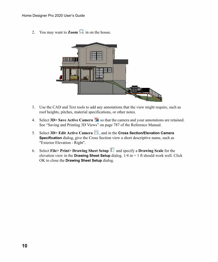
2. You may want to Zoom in on the house.
3. Use the CAD and Text tools to add any annotations that the view might require, such as roof heights, pitches, material specifications, or other notes.
4. Select 3D> Save Active Camera so that the camera and your annotations are retained. See “Saving and Printing 3D Views” on page 787 of the Reference Manual.
5. Select 3D> Edit Active Camera , and in the Cross Section/Elevation Camera Specification dialog, give the Cross Section view a short descriptive name, such as "Exterior Elevation - Right".
6. Select File> Print> Drawing Sheet Setup and specify a Drawing Scale for the elevation view in the Drawing Sheet Setup dialog. 1/4 in = 1 ft should work well. Click OK to close the Drawing Sheet Setup dialog.

Sending Elevation Views to Layout
11
7. Select File> Send to Layout to open the Send to Layout dialog.
• Under Send Position, leave Show Layout Page checked so that when you click OK, the layout window will become active.
• Under Send Options, select Current Screen.• Under Camera View Options, select Plot Lines and leave Color Fill unchecked. See
“Plot Line Views” on page 962.• Confirm that the view is being sent to layout using the same Scale as in the Drawing
Sheet Setup dialog.• When Orthogonal Views such as Cross Section/Elevation views are sent to layout, you
can specify line weights for surface edge lines and pattern lines. You can also leave these boxes unchecked to use the line weight settings assigned to the individual objects and patterns in the view. See “Send To Layout Dialog” on page 959 of the Reference Manual.
8. Click OK.

12
Home Designer Pro 2020 User’s Guide
9. Return to the elevation view, then select File> Close to close the view. In the Update View to Layout dialog, click OK. If you had made changes in the elevation view, clicking OK would update those changes to the layout view. In this case, no changes were made, so it doesn’t matter.
10. Return to floor plan view. A camera symbol now displays, indicating the position of your saved elevation camera.
11. Repeat this process for any additional desired elevation views. If sending more than one elevation view to the same page, keep in mind that the elevation views will need to be selected and repositioned so that they are not stacked on top of one another on the page.
Sending Perspective Views to LayoutPerspective views add visual appeal and clarity to your documentation. They are converted to bitmap images when sent to layout, which means that they increase your file size considerably. As a result, you should send perspective views to layout sparingly.
To send a perspective view to layout1. Return to floor plan view.
2. Select 3D> Create Perspective View> Full Camera and create a 3D view.

Sending Perspective Views to Layout
13
3. In the camera view, use the Move, Orbit and Tilt Camera tools available in the 3D menu to adjust the view to your liking. See “Editing 3D Views” on page 781 of the Reference Manual.
4. Select File> Send to Layout to open the Send to Layout dialog.
• Under Send Options, select Current Screen. • Under Camera View Options, select Live View and Update on Demand. See “Semi-
Dynamic Views” on page 962.
5. Click the Select Objects button, then click on the view to select it.

14
Home Designer Pro 2020 User’s Guide
• Notice that in the Status Bar, it is described as a Picture File Box rather than a Layout Box.
6. Use the box’s edit handles to resize and crop the image as needed: • Click and drag a corner Resize handle to change the size of the picture box while
maintaining its aspect ratio.• Click and drag a side Reshape handle to crop the extents of the picture within the box.• For more information about editing picture boxes, see “Editing Pictures, Metafiles,
and PDF Boxes” on page 839 of the Reference Manual.
Repeat this process for any other camera views you may want to send to layout.
Printing to PDFA PDF, or Portable Document Format, file saves all of the printable information associated with a document such as a layout and makes it available for both viewing and printing without using the software originally used to create it. PDFs are easy to create and provide you with an efficient way to share your work with others or send documents to a print service.
Home Designer Pro has a built-in PDF writer, which you can select as your printer in any of the program’s Print dialogs. Alternatively, you can print to PDF using a PDF writer installed on your computer. For more information, see “Printing to a PDF File” on page 982 of the Reference Manual.