Laser Based Manufacturing in Micro-Processing and … presentations... · Laser Based Manufacturing...
51
Laser Based Manufacturing in Micro-Processing and Energy Juergen Stollhof Program Manager Micro Processing TRUMPF Inc. Farmington, CT
Transcript of Laser Based Manufacturing in Micro-Processing and … presentations... · Laser Based Manufacturing...

Laser Based Manufacturing in
Micro-Processing and Energy
Juergen Stollhof
Program Manager Micro Processing
TRUMPF Inc.
Farmington, CT

Disk Laser Technology 2
Content
Material ablation with Short and Ultrashort Laser Pulses
High Power Cavity Dumped Disk Laser
- Principle and Technology
- Application for Solar Cells and Turbine Plates
Ultrashort Disk Lasers
- Regan Disk Amplifier
- Applications: Micro Processing and Precision Drilling
Summary
Disk Laser Technology 3
Material ablation with Short
and Ultrashort Laser Pulses

Disk Laser Technology 4
The optimum machining process
Structuring
ps
10 GW / mm²
Sublimation
and direct
dissociation
Ablation,
engraving
ns
10 MW / mm²
Vaporization
and ionization
Drilling
ms
1 MW / mm²
Vaporization
Heat
conduction
welding
ms
1 kW / mm²
Melting
Deep
penetration
welding,
cutting
Hardening,
soldering
Process examples
mssInteraction time
10 kW / mm²30 W / mm²Power density
starting from
Melting and
vaporization
HeatingMain effect
Heated material
Molten material
Vapor
--- Ejected material
Power density and interaction time determine how much energy is delivered to the workpiece and what the resulting effects will be. Shown here: metals.

Disk Laser Technology 5
Efficiency
of the
ablation process
Ablation threshold decreasing with pulse duration
Ablation rate per pulse increases with pulse energy
Higher efficiency
shorter pulse duration
increased pulse energy
increased frequencyHigher average power
Disk Laser Technology 6
High Power Cavity Dumped Disk Laser
- Disk Technology
- Cavity Dumping
- Applications

Disk Laser Technology 10
DP
Pumped Spot
PL ~ Dp2
A certain laser power can be extracted
per unit of area
D p
TLS Disk - Cavity
Scalability of Laser Output Power

Disk Laser Technology 11
0 kW
5 kW
10 kW
15 kW
20 kW
Output
Scaling by Disk Coupling to 20 kW CW
Pump Current (a.u.)
1 disk: 5.5 kW
2 disks: 10.7 kW
4 disks: 20.0 kW

Disk Laser Technology 13
Pulsmode Q-switching
OC Disk, Heatsink
R Disk, Heatsink
Characteristics:
• Loss modulation
• Beamquality and pulse duration are correlated
HT
Pulsmode Cavity Dumping
Characteristics:
• Modulation of OC
• no correlation BPP and pulse duration
• Pulse is formed by EO-Switch

Disk Laser Technology 14
Modes of Operation: Q-Switching
Loss
Output Coupling
Output Power
Time
Time
Pulse duration 100 ns - µs
Power inside
Resonator
Coupled Pulse Formation and Output Coupling

Disk Laser Technology 15
Modes of Operation: Cavity Dumping
Time
Time
Pulse duration 10 ns - µs
Pulse Formation and Output Coupling not coupled
Output Power
Power inside
Resonator
Loss
Output Coupling

Disk Laser Technology 16
photodiode triggers timing of output coupling
stable even at high repetition rates
short pulses even at long resonators ⇒ good beam quality
Cavity-dumping Scheme
Polarizer
Yb:YAG DiskPockels-Cell
HR
Photodiode
HR

Disk Laser Technology 17
Highest throughput with short pulses – Cavity-dumping enables short pulses –
Pulse duration: 30ns
Energy stability: RMS < 5%

Disk Laser Technology 18
Highest throughput with short pulses
fiber delivered ns Disk Laser -
400* - 800µmFiber Core diameter
5 – 100
80
30
750
1030
TruMicro 7050
kHz
mJ
ns
W
nm
Average power
Repetition rate
Max. pulse energy
Pulse duration
Wavelength
*special configuration allows smaller fiber core diameter

Disk Laser Technology 19
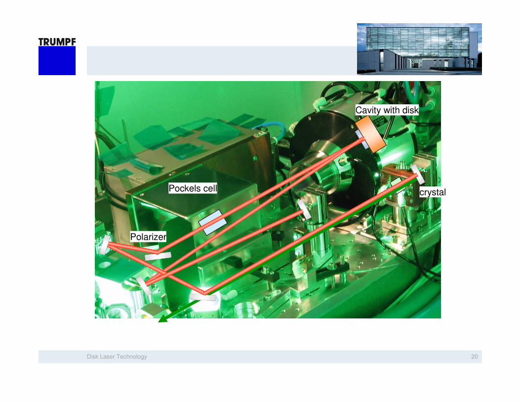
crystal
Cavity with disk
Pockels cell
Polarizer
Concept SHG
Green-emitting nanosecond disk laser
Disk Laser Technology 20
crystal
Cavity with disk
Pockels cell
Polarizer
Disk Laser Technology 21
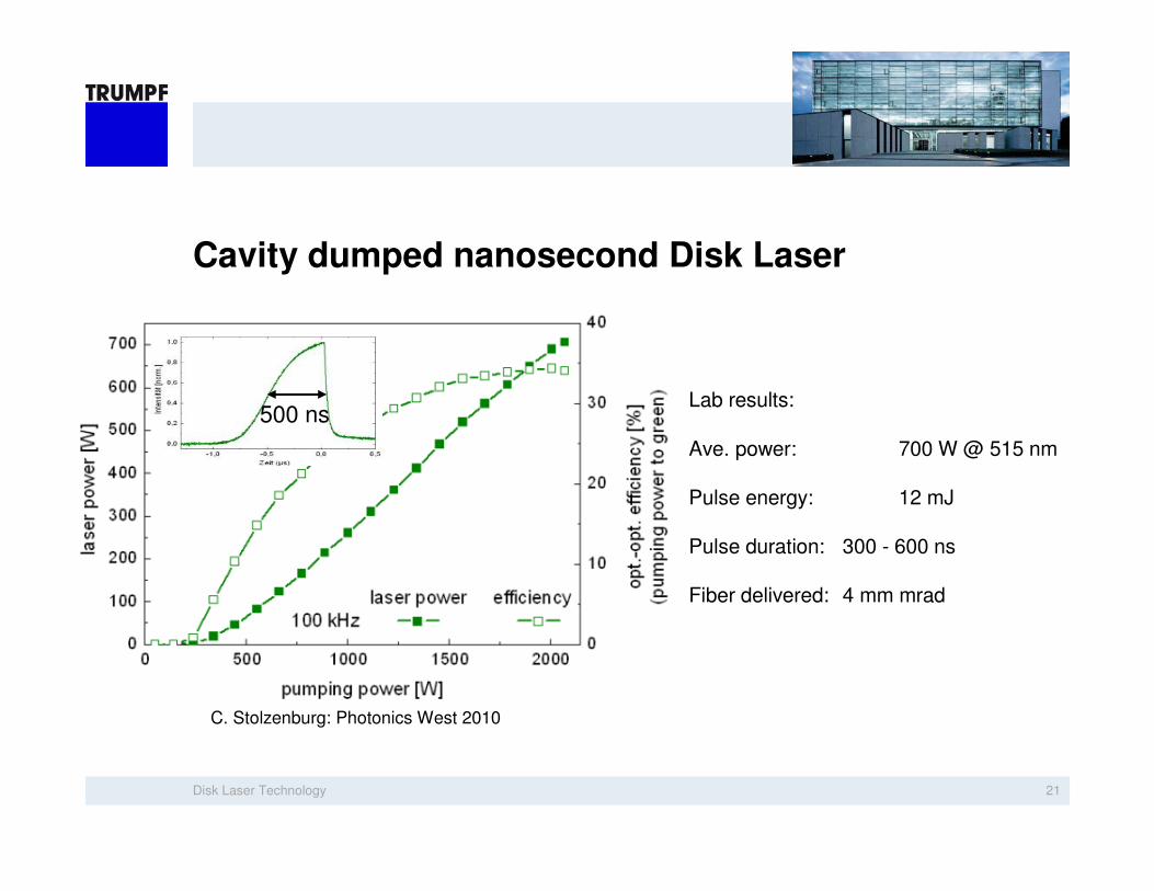
Cavity dumped nanosecond Disk Laser
Lab results:
Ave. power: 700 W @ 515 nm
Pulse energy: 12 mJ
Pulse duration: 300 - 600 ns
Fiber delivered: 4 mm mrad
500 ns
C. Stolzenburg: Photonics West 2010
Disk Laser Technology 22
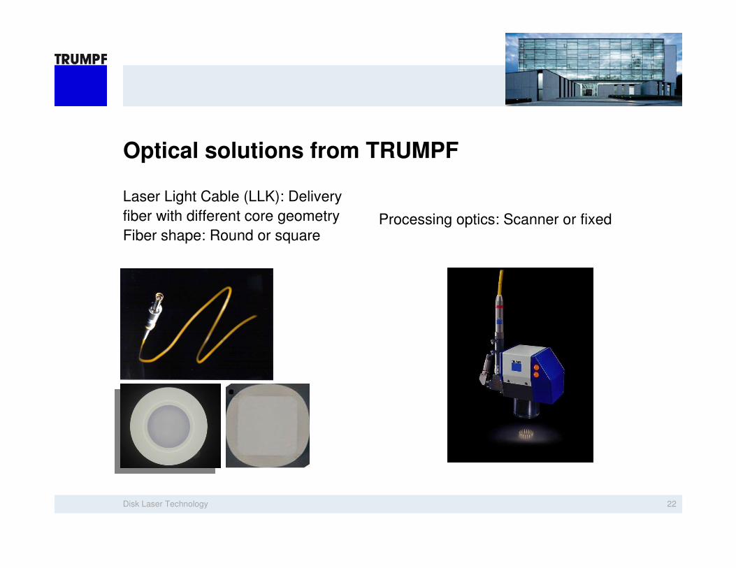
Optical solutions from TRUMPF
Laser Light Cable (LLK): Delivery
fiber with different core geometry
Fiber shape: Round or squareProcessing optics: Scanner or fixed

Disk Laser Technology 23
Productivity
M
r Mr
a
39,2 cm²/s37,5 cm²/s25 cm²/s +50% +5%
+ 57 %
a
a

Disk Laser Technology 24
Edge Deletion of Thin Film Solar Cells
Laser deletion through Glass Plate
Transmission > 77 %
(Note: uncoated glass-plate: T = 92 %)
Surface Resistivity > 100 MΩ
High power short pulse laser required

Disk Laser Technology 25
Laser Edge Deletion through Glass-Plate
Aim: Replacement of sand blasting due to environmental aspects
Requirements: High removal rates
Result:: Optical transparent and electrical isolated edge
Laserbeam
Glass
Front Contact
Absorber
Back Contact

Disk Laser Technology 26
PV: Laser Edge Deletion – TruMicro 7050
Removal rates increased by quadratic fibers
Ablation rate up to 50 cm²/s – through glass
High transmission through delaminated area
Insulating resistance > 100 MΩ
Disk Laser Technology 28
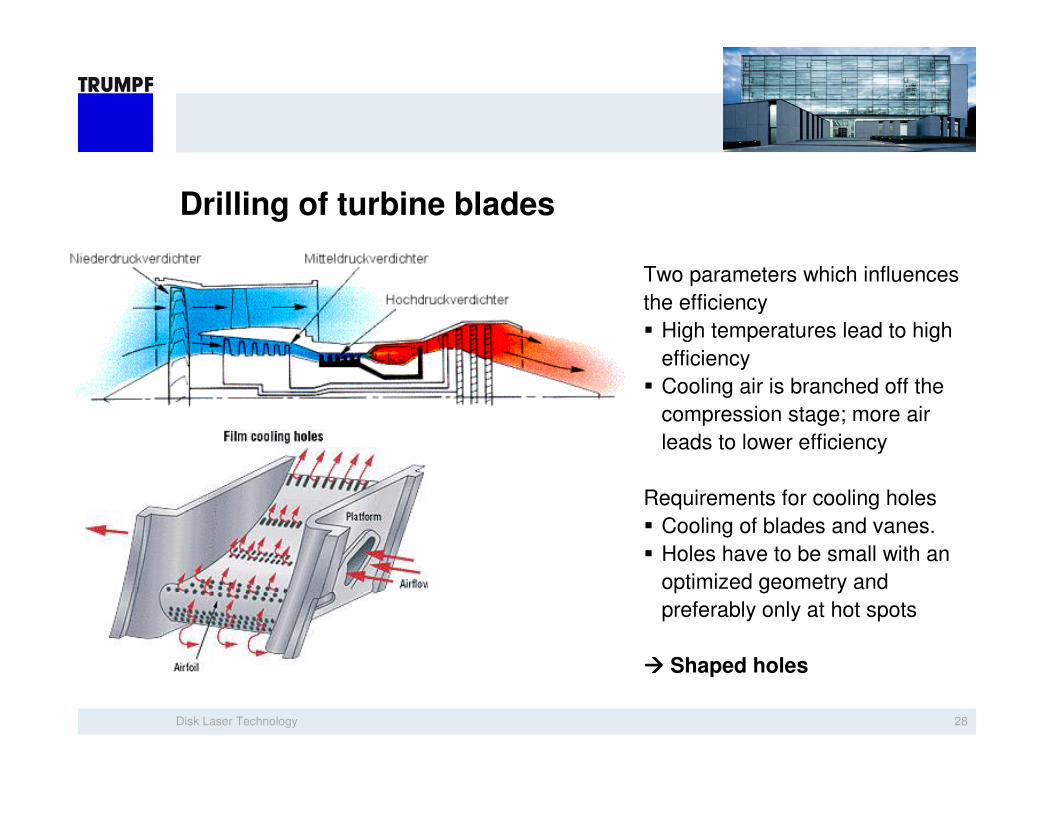
Drilling of turbine blades
Two parameters which influences
the efficiency
High temperatures lead to high
efficiency
Cooling air is branched off the
compression stage; more air
leads to lower efficiency
Requirements for cooling holes
Cooling of blades and vanes.
Holes have to be small with an
optimized geometry and
preferably only at hot spots
Shaped holes

Disk Laser Technology 29
Drilling of cooling holes in turbine blades
Application:
Hole drilling in bare metals using
the TruMicro 7050
Result:
90 and 45 degree hole drilling in
bare metals.
The holes have very little taper and
minimal HAZ and recast.
The holes are being drilled in less
than 1 second.
Source: CCAT, ICALEO 2010

Disk Laser Technology 30
Shaped holes - laser ablation
Application: Ablation
Ablation (shaping) process done with Scanner
(here about ~ 80 passes)
Max. recast layer: < 50µm
Roughness: Ra < 10µm

Disk Laser Technology 31
Ultrashort Disk Lasers
- Regan Disk Amplifier
- Applications

Disk Laser Technology 32
Motivation – Why shorter than short?
Precise micro-processing without
burr or melt formation
Cold micro-processing

Disk Laser Technology 33
Influence of Pulse Duration on Quality
Pulse Duration
melt
deb
ris
no
nlin
ear
effe
cts
pre
cis
ionQ
ua
lity

Disk Laser Technology 34
Scaling the average power of ps lasers
Rod-type amplifiers:
- Limited in average power due to thermal effects
Disk technology
- High peak power, but big beam diameter in active medium
Moderate intensity
Advantages:
- High surface to volume ratio
- Superior heat management
- High average powers with good beam quality
- No nonlinear effects
D p
PL ~ Dp2

Disk Laser Technology 35
Obtaining ps-Pulses
ps (and fs) Oscillators:
Tens of MHz Repetition Rate (given by resonator length)
Pulse selection to lower Repetition Rate
Pulse Energies in nJ scale
Amplification needed (5 orders of magnitude)
Time
Energ
y Oscillator
Pulse Train
Selected
Pulses
Amplified
Pulses
Pulse
Selection
Amp.
Amplifier

Disk Laser Technology 37
Features:
Variable energy (proportional to external analog input or programmed internally)
Pulses triggerable, (e.g. every 2nd pulse)
Advantages:
No first pulse issues! (precisely controlled energy for every pulse)
No variation of output beam properties (focus position, diameter, M²) with power!
External Modulator

Disk Laser Technology 38
TruMicro 5050 – Power and Pulse Duration
Average Power: >50 W (max. 65 W)
Optical Efficiency: 50%
>300µJ @ Repetition Rate: 200 kHz
Pulse Duration: 6 ps (sech2 Fit)
Spectral Width: 1 nm (FWHM)
0
10
20
30
40
50
60
Outp
ut P
ow
er
(W)
Pump Power-50 -40 -30 -20 -10 0 10 20
1028 1030 1032 1034Inte
nsity (
a.u
.)Delay (ps)
Wavelength (nm)
set point
Disk Laser Technology 39
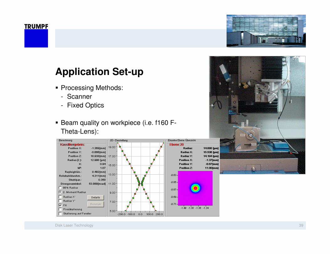
Application Set-up
Processing Methods:
- Scanner
- Fixed Optics
Beam quality on workpiece (i.e. f160 F-
Theta-Lens):

Disk Laser Technology 42
TruMicro Series 5000 compact (~1000x600mm²)
M² < 1.3
200-800 kHz
150 µJ
< 10 ps
515 nm
30 W
TruMicro 5250
343 nm1030 nmWavelength
M ² < 1.3
200-800 kHz
250 µJ
< 10 ps
50 W
TruMicro 5050
M² < 1.3Beam Quality
200-800 kHzRepetition Rate
50 µJMax. Pulse Energy
< 10 psPulse Duration
10 WMax. Average Power
TruMicro 5350

Disk Laser Technology 44
TruMicro 5050 - Stability
Guaranteed Power stability < 1,5% for ambient temperatures of 20 – 30 °C
Guaranteed Energy Stability: < 2% (RMS) 2500
2000
1500
1000
500
0
Counts
-2 -1 0 1 2
Energy deviation (%)
20k pulsesRMS 0.30%
Pow
er
(Wa
tt)
0
10
20
30
40
50
Time (hours)0 10 20 30 40 50 60 70
Tem
pera
ture
(°C)
10
15
20
25
30
35
40

Disk Laser Technology 45
Patterning for Thin Film Solar Cells
P1: Patterning of front contact (TCO) through the Glass (IR)
P2: Patterning of absorber through the Glass + TCO (green)
P3: Patterning of back contact and absorber through the Glass + TCO (green)
Connection of Cells on a Module
Glass
TCO
Absorber
Back Contact
P1 P2 P3

Disk Laser Technology 46
PV: Thin Film Ablation
Laser patterning of thin CIGS
Advantages:
- Burr free
- Melt free
- No delamination
- High speed (> 0,5 m/s)
Application: P2 step for CIGS cell
connection

Disk Laser Technology 47
PV: Thin Film Ablation
Laser patterning of thin TCO on CIGS
Advantages:
- Burr free
- Melt free
- No delamination
- High speed (> 1,2 m/s)
Application: P3 step for CIGS cell
connection
Disk Laser Technology 48
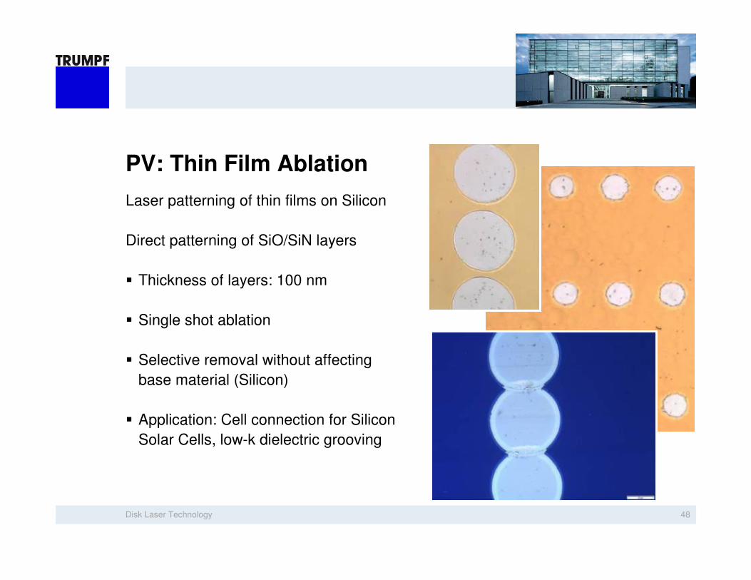
PV: Thin Film Ablation
Laser patterning of thin films on Silicon
Direct patterning of SiO/SiN layers
Thickness of layers: 100 nm
Single shot ablation
Selective removal without affecting
base material (Silicon)
Application: Cell connection for Silicon
Solar Cells, low-k dielectric grooving

Disk Laser Technology 50
Automotive: Drilling with high Aspect Ratio
Helical Drilling of Stainless Steel
No melt or debris
No Heat Affected Zone
Free selection of taper (positive,
negative or zero)
Diameters: 50 to 100 µm
Material thickness: up to 1.5 mm
Applications: Injectors
Disk Laser Technology 52
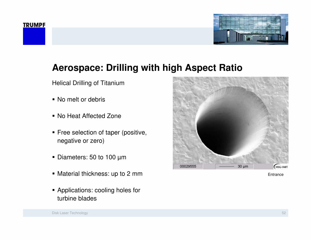
Aerospace: Drilling with high Aspect Ratio
Helical Drilling of Titanium
No melt or debris
No Heat Affected Zone
Free selection of taper (positive,
negative or zero)
Diameters: 50 to 100 µm
Material thickness: up to 2 mm
Applications: cooling holes for
turbine blades
Entrance

Disk Laser Technology 53
Drilling of Green Ceramic Foils
Drilling on the fly (percussion)
Diameter < 100 µm
Drilling rate: > 800-1000 holes/sec
Negligible melting of Mylar tape on
backside

Disk Laser Technology 54
Cutting Semiconductors
Silicon Wafer Dicing
Small cutting kerf (< 20 µm)
Low HAZ
High quality of cutting edge
High productivity due to high
average power

Disk Laser Technology 56
Stent Cutting with TruMicro Series 5000
Highest quality cutting process
- Negligible burr formation
- Negligible HAZ
Materials (e.g.):
- CrCo
- Nitinol
- Polymers
- Absorbable Materials
Reduction of scrap at the
beginning of the process chain
Saving of expensive materials
Saving of expensive finishing
processes

Disk Laser Technology 57
Cutting of Nitinol

Disk Laser Technology 58
Cutting of Polymers
Disk Laser Technology 61
Summary

Disk Laser Technology 62
Absorption rate (at 20°C)
0
20
40
60
80
100
0,1 1 10
Wavelength in µm
Ab
so
rpti
on
in
% Glass
FeAl
Ag
Cu
CO2λλλλ=10,6 µm
Solid State λλλλ ~1 µm
Diodeλλλλ ~ 850 nm
IRUV
30,3
SHGλλλλ=5xx nm
THGλλλλ=3xx nm
FHGλλλλ=2xx µm

Disk Laser Technology 64
Parameters
WavelengthWavelength
Peak powerPeak power
Pulse Pulse lengthlength
BeamBeam qualityquality
feasibilityfeasibility
High High frequencyfrequency
oror cw mode cw mode
⇒⇒ aveave. power. power
economicaleconomical
stabilitystability......
......fromfrom pulse to pulse.pulse to pulse.
…… beambeam qualityquality
RepeatabilityRepeatability

Disk Laser Technology 65
Application demands
Remote cutting and ablation
Pulses short enough to vaporize
material
q-switching, davity dumped or
modelocking
Scanner for fast beam steering
High beam quality
Stability from Pulse to pulse
Reliability of the process

And now I’m looking forward to your questions!
Juergen Stollhof
TRUMPF Inc.
5 Johnson Ave
Farmington, CT 06032