
LASER Laser Processing of Sapphire - pro-physik.de
4
20 Physics’ Best April 2017 © 2017 Wiley-VCH Verlag GmbH & Co. KGaA, Weinheim LASER We demonstrate how lasers can be applied for processing of sapphire. Based on this example, we show how novel laser material processes are being qualified and how diffe- rent material qualities as well as process requirements regarding speed and accuracy define an ap- plicative solution consisting of a combination of laser source and processing optics. Thus, one thing becomes particularly apparent: ap- plication know-how matters. D ue to its outstanding material properties, sapphire is one of the most interesting materials for technical use. Because of decrea- sing material costs and improved machining processes, sapphire becomes more and more interes- ting for various high volume products replacing conventional glasses. At the beginning of the 20 th century, sapphire’s indus- trial use was pioneered by watch industry, employing sapphire as watch glass and later – in form of ruby – as mechanical bearing for clockworks of premium wrist watches. Meanwhile, sapphire has found applications in consumer electronics (e.g., as part of the display or as camera window in mobile electronic devices), as substrate for LED production or as window material for sensors. It is also used for endoscopic lenses and still proofs its use as mechani- cal bearing in watches or measu- ring tools. These fields of application all make use of one or more of sap- phire’s material properties: Sapphire permits very high optical transmis- sivity, it is electrically insulating but still possesses a high thermal con- ductivity. For handling, sapphire is absolutely acid-proof. Furthermore, it is one of the hardest materi- als known: Sapphire possesses a value of 9 on the Mohs scale of mineral hardness and is listed next to diamond which has a value of 10 [1] . This property is particularly interesting for the use in displays and as protection window. Chemically, sapphire is an alu- minum-oxide (Al 2 O 3 ) in a trigonal crystal lattice structure differentia- ting it from glass which possesses an amorphous, silicon-based struc- ture. It is called ruby if chromium atoms are incorporated into the lat- tice structure by which the material appears red. For its industrial use, sapphire is synthetically grown in a monocrystalline structure. Today, the majority of global sapphire production is used as sub- strate for crystallization of mono- crystalline gallium nitride (GaN), the base material for blue, white, and green LEDs. Because of the rapid growth of LED production for large-scale flat-screen televisions and lighting purposes, production of sapphire has become more ef- ficient and cost-effective due to economies of scale and rationaliza- tion. Hence, prices of sapphire wa- fers rapidly dropped which allows a broader consideration of sapphire in mass products besides LEDs and lighting applications [2] . The tool of choice Due to its hardness, sapphire im- poses a special challenge in mate- rial machining since it does not only require tools which are able to cope with its hardness but also treat the brittle material delicately. Mechanically, sapphire can only be machined by diamond tools, e.g., diamond tipped saws. However, mechanical cutting is expensive: Processing speeds are comparably slow and lifetime of tools and ma- terial yields are limited. Alterna- tively, lasers machine sapphire in an affordable and more economic manner, since this contact-free pro- cessing method shows no tooling wear and has higher processing yields (Fig. 1). The availability of af- fordable sapphire wafers combined with laser machining, established sapphire as material used for poten- tial production numbers of several Laser Processing of Sapphire How material properties and process requirements determine the optimal laser process. Michael Berndt and Markus Danner Dr. Michael Berndt, Coherent-Rofin, Zeppelinstraße 10 - 12, 82205 Gilching, Germany www.rofin.de Markus Danner, Coherent Schweiz, Aemmenmattst. 43, 3123 Belp, Switzer- land Fig. 1 Laser fusion cutting of a sapphire wafer with a pulsed fiber laser and fixed optics
Transcript of LASER Laser Processing of Sapphire - pro-physik.de

20 Physics’ Best April 2017 © 2017 Wiley-VCH Verlag GmbH & Co. KGaA, Weinheim
L A S E R
We demonstrate how lasers can be applied for processing of sapphire. Based on this example, we show how novel laser material processes are being qualified and how diffe-rent material qualities as well as process requirements regarding speed and accuracy define an ap-plicative solution consisting of a combination of laser source and processing optics. Thus, one thing becomes particularly apparent: ap-plication know-how matters.
Due to its outstanding material properties, sapphire is one of
the most interesting materials for technical use. Because of decreasing material costs and improved machining processes, sapphire becomes more and more interesting for various high volume products replacing conventional glasses. At the beginning of the 20th century, sapphire’s industrial use was pioneered by watch industry, employing sapphire as watch glass and later – in form of ruby – as mechanical bearing for clockworks of premium wrist watches. Meanwhile, sapphire has found applications in consumer electronics (e.g., as part of the display or as camera window in mobile electronic devices), as substrate for LED production or as window material for sensors. It is also used for endoscopic lenses and still proofs its use as mechanical bearing in watches or measuring tools.
These fields of application all make use of one or more of sapphire’s material properties: Sapphire permits very high optical transmissivity, it is electrically insulating but still possesses a high thermal conductivity. For handling, sapphire is absolutely acidproof. Furthermore, it is one of the hardest materi
als known: Sapphire possesses a value of 9 on the Mohs scale of mineral hardness and is listed next to diamond which has a value of 10 [1]. This property is particularly interes ting for the use in displays and as protection window.
Chemically, sapphire is an aluminumoxide (Al2O3) in a trigonal crystal lattice structure differentiating it from glass which possesses an amorphous, siliconbased structure. It is called ruby if chromium atoms are incorporated into the lattice structure by which the material appears red. For its industrial use, sapphire is synthetically grown in a monocrystalline structure.
Today, the majority of global sapphire production is used as substrate for crystallization of monocrystalline gallium nitride (GaN), the base material for blue, white, and green LEDs. Because of the rapid growth of LED production for largescale flatscreen televisions and lighting purposes, production of sapphire has become more efficient and costeffective due to economies of scale and rationalization. Hence, prices of sapphire wa
fers rapidly dropped which allows a broader consideration of sapphire in mass products besides LEDs and lighting applications [2].
The tool of choice
Due to its hardness, sapphire imposes a special challenge in material machining since it does not only require tools which are able to cope with its hardness but also treat the brittle material delicately. Mechanically, sapphire can only be machined by diamond tools, e.g., diamond tipped saws. However, mechanical cutting is expensive: Processing speeds are comparably slow and lifetime of tools and material yields are limited. Alternatively, lasers machine sapphire in an affordable and more economic manner, since this contactfree processing method shows no tooling wear and has higher processing yields (Fig. 1). The availability of affordable sapphire wafers combined with laser machining, established sapphire as material used for potential production numbers of several
Laser Processing of Sapphire How material properties and process requirements determine the optimal laser process.
Michael Berndt and Markus Danner
Dr. Michael Berndt, Coherent-Rofin, Zeppelinstraße 10 - 12, 82205 Gilching, Germany www.rofin.deMarkus Danner, Coherent Schweiz, Aemmenmattst. 43, 3123 Belp, Switzer-land
Fig. 1 Laser fusion cutting of a sapphire wafer with a pulsed fiber laser and fixed optics

© 2017 Wiley-VCH Verlag GmbH & Co. KGaA, Weinheim Physics’ Best April 2017 21
L A S E R
hundred million parts per year as required for mass applications, e.g., in consumer electronics.
Three different methods
Laser cutting of sapphire is generally distinguished by three processing methods. Their difference is determined by the underlying physical principle leading to separation of the material:n fusion cutting,n ablation cutting, andn cutting with CoherentRofin SmartCleave FI process.
Fusion cutting melts sapphire material. For this, laser energy is focused along the contour line where the sapphire material is supposed to be separated. This is carried out successively, i.e., one point of the contour line after the other is melted. While the laser melts the material, molten material is removed from the area by pressure of a process gas delivered by a gas nozzle resul ting in an emerging kerf
of about 30 – 80 µm. The excess material is blown away in the direction of the laser beam (Fig. 2a). Due to the high melting point of sapphire of about 2000 °C, this process is typically initiated by pulsed fiber lasers and the laser beam is brought to the sapphire material by a fixed optical processing head.
In contrast, ablation cutting predominantly evaporates the solid material into gas form and skips the phase transition from solid to liquid material as it happens in fusion cutting (Fig. 2b). Resulting gases evaporate in direction from which the laser beam is originating. In order to start this process, high laser power and high laser intensities are necessary. Hence, ultrashort pulse lasers in combination with galvanometerscanner (galvo) optics are employed. The galvo scanner guides the laser beam successively trace after trace along the contour of the cut, deepening the originating kerf by each track. The kerf itself possesses a width of 20 – 50 µm. Due to the constant ablation of material,
this process can also be employed for engraving of sapphire.
The CoherentRofin SmartCleave FI process offers a patented, specific lens system which makes use of nonlinear optical effects and allows to create thin filaments within the sapphire material. These filaments are deliberate cracks, induced by photoacoustic compression occurring when the laser beam is focused through the material. The filaments are oriented in perpendicular direction to the surface and placed in discrete distances of a few micrometer from each other along the contour which is supposed to be cut (Fig. 2c). By introduction of filaments, sapphire material is weakened along the contour of the cut. Due to this, remaining material “bridges” between the filaments can crack. The originating gap between inner and outer contour is small and in the range of only 0.5 to 1.0 µm. Hence, friction along the cracks does not allow the inner and outer contour to separate. In order to cleave both
Fig. 3 Pulsed fiber laser (Coherent-Rofin StarFiber 200 OEM) in combination with single or three-fold FLBK 60 processing head for fusion cutting of sapphire. The FLBK 60 processing head is available in versions enabling parallel processing by energy sharing of the laser.
Fig. 2 Schematic comparison of fusion cutting (a), ablation cutting (b), and cutting with Coherent- Rofin SmartCleave FI optics (c). Typi-cal dimensions are given.
SAPPHIRESAPPHIRE SAPPHIRE
Heat-a�ected zone
LaserLaser Laser
0.5 – 1.0 µm 20 – 50 µm 20–50 µm
Ablation cuttingFusion cutting
FI Optic
2 mm 2 mm
Galvo OpticFLBK 60 + Cutting nozzle
SmartCleave FI
Heat-a�ected zone
30 – 80 µm
SAPPHIRE
a b c

22 Physics’ Best April 2017 © 2017 Wiley-VCH Verlag GmbH & Co. KGaA, Weinheim
L A S E R
parts, thermal stress is induced by a CO2laser along the contour of the filament cracks. The heated areas of the material expand and crack the nondesired part of the material. Consequently, inner and outer contour separate. In order to achieve the nonlinear optical effects necessary to start this process, high intensities of ultrashort pulse lasers have to be applied. Additionally, a CO2laser is necessary in order to allow cleavage.
Material qualities of sapphire
There are different material qualities of sapphire available. Hence, two sapphire crystals are not necessarily similar and differences in quality can have an impact on the result of the chosen laser process.
Differences in material quality are already induced by different synthetic growth processes of the material. Generally, there are three different commercially used growth processes for sapphire crystals:n The Verneuil process is used for growing smaller crystals of about 30 – 35 mm diameter.n The Kyropoulos process is used for growing large crystals of 200 to 300 kg in weight. From this, crystal cores of two up to four inch (about 50 – 100 mm) in diameter are drilled and cut to wafers.n The EFG (edgedefined filmfed growth) process allows to grow crystal sheets of a thickness of some millimeters or less, close to the thickness of the final product. Hence, slicing of EFG crystals or cutting them to wafers is obsolete
and processing costs are reduced. The crystal sheet is grown from the melt in between a defined frame. This process allows faster growth than the Kyropoulos process and can therefore be economically more interesting. However, crystal sheets grown by the EFG process possess an anisotropy, i.e., a preferred direction along the drag of the crystal as well as a slightly corrugated surface. This can cause a disadvantage in later stages of material processing depending on the chosen laser cutting process.
To summarize, we can define a set of material qualities of sapphire which determine the characteristics of the material and have to be considered when choosing the laser process:n Sapphire grown with either the Verneuil, the Kyropoulos, or the EFG process. Material grown with the EFG process is more demanding when it comes to processing of the material.n Different material thicknesses, ranging from some 1/100 mm to several millimeters.n Polished or unpolished material surfacesn Colored (e.g. ruby) or transparent materialn Even or uneven material surfaces
Choice of equipment
A critical requirement for the customer is the edge quality of the product. The required edge quality is determined by the final purpose of the product. At the same time, the achievable edge quality depends on the combination of mate
rial quality and properties (e.g., material thickness) and the chosen laser process. Additionally, process para meters like process speed play a role, leading directly to costs in general which obviously also have strong impact on the choice of equipment.
For selecting the laser process, one has three general options as discussed above. Each choice of process is linked to a specific set of equipment: Fusion cutting is typically carried out by a pulsed fiber laser in combination with a material cutting processing head (Fig. 3). Ablation cutting is mostly employed for engraving purposes and is realized with a femto second laser in combination with a galvanometerscanner optics. The third process is carried out with a picosecond ultrashortpulse laser in combination with the CoherentRofin SmartCleave FI optics in order to separate the sapphire material. In any case, pulsed lasers are required because of their high intensity which is necessary to process sapphire.
Cutting with CoherentRofin StarFiber P in combination with FLBK 60 processing heads achieves cutting speeds of 10 to 30 mm/s depending on material thickness. Chipping at the material’s edges is in the range of 10 µm and values for surface roughnesses are of about Ra ~ 1 µm. This solution is well suited for polished and unpolished, transparent and colored Kyropoulos grown sapphire crystals of up to 1 mm thickness. Due to the good quality of the cut, processed material does not require post processing – ideal for cutting of inner contours
Fig. 4 Exemplary samples of sapphire cut materials. Sapphire wafer cut with fu-sion cutting process in typical dimensi-ons of a smartphone (a); Edelweiss figure cut from sapphire wafer with fusion cut-
ting process, demonstrating the perfor-mance of fusion cutting also for complex structures (b); Scanning electron microscopy image of a sapphire wafer cut with Coherent-Rofin SmartCleave FI.
Pictured is the cut and cleaved edge of the wafer with the individual filaments brought into the material. The scale of 60 µm nicely pictures the high precision of the process (c).
a b c
L A S E R
(Fig. 4a, b). However, with increasing material thickness, edge chipping is increased as the heat affected zone in the material is extended during processing. For example, watch glasses of a thickness of up to 4 mm therefore inevitably require grinding and polishing after laser processing.
Customers emphasizing economical parameters can be accounted for by employing energy sharing. Here, the energy exiting the laser is split and distributed to more than one working station. The StarFiber P can be complemented with FLBK 60 double, triple, or quadprocessing heads for higher throughput. Hence, the equipment can be optimized to costs very well.
Ablation cutting has some limitations regarding the angularity of the cut that usually depends on the focal length of the processing optics. It determines the cone angle of the beam and therefore the cut surface is usually tapered by several degrees. The process is approximately 50 % slower than fusion cutting, but the surface roughness of Ra ~ 0.4 µm is excellent.
The process with a picosecond ultrashort pulse laser and SmartCleave FI Optics enables for fast cutting speeds of about 500 mm/s. However, the process is depending on the surface quality of the raw material. The sapphire wafer has
to be polished when processed. In terms of color, processed sapphire should be transparent to the laser wavelength. Consequently, any coating on the wafer which is not transparent to the laser wavelength proves to be difficult to cut. However, the quality and speed of cuts is highly improved compared to fusion cutting. There are no heat affected zones in the material and chipping is reduced to a few micrometers (Fig. 4c). Process speed can be about ten times faster than with fusion cutting. Hence, this process is well suited for highthroughput cutting in volume production of outer contours of polished sapphire when high edge quality cuts are desired. But for cleaving, a second laser process with a CO2 laser is necessary, and equipment costs for this technique are higher.
Summary and outlook
We have shown how sapphire can be processed with different types of laser equipment. The laser processing of sapphire is key to the material’s application in consumer electronics which promises potential production numbers of several hundred million parts per year, e.g., for lenses or displays of mobile phones. The choice of laser equipment is determined by material
quality and material properties of the sapphire substrate, the requirements for the final product as well as requirements regarding process parameters and costs. All these parameters need to be considered when laser equipment is chosen – regardless if sapphire or any other material is processed. And it has become quite clear that only a deep understanding of all these parameters in combination with vast application knowledge and a dedicated range of equipment allow customers to get an optimal solution for their individual requirements.
AcknowledgementsWe acknowledge the support by Meyer Burger Technology AG, Thun, Switzerland, for provi ding sapphire wafers as well as Dr. Roland Mayerhofer for proof reading the manuscript and Susanne Lötzsch and Petra Wallenta, Coherent Inc., as well as Stephanie Kurz of Coherent Schweiz for supporting the artwork.
Since November 07, 2016, Rofin is part of the Coherent family (www. coherent.com).
[1] C. Rüttimann, Laser Tech. J. 11, 3 (2014) [2] M. Danner, Laserschneiden und Laser
bohren von Saphirglas, Mikroproduktion 4/2013
Vacuum Technology
PINK GmbH Vakuumtechnik · Gyula-Horn-Str. 20 · 97877 WertheimT +49 (0) 93 42 872-0 · [email protected] · www.pink-vak.de
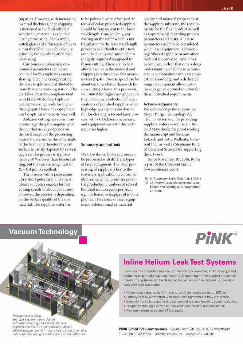
Inline Helium Leak Test SystemsBased on its comprehensive vacuum technology expertise, PINK develops andproduces tailor-made leak test systems. Depending on the customer’s require-ments, the systems can be designed for partially or fully automatic operationwith very high cycle rates.
• Helium leak rates up to 10-8 mbar x l x s-1, test pressure up to 300 bar• Partially or fully automated with robot loading/materials flow integration• Extension to include gas mixing station and test gas recovery system possible• Programmable logic controller, visualisation and data documentation• Remote maintenance and 24 h support
Fully automatic inlineleak test system in twin designwith robot carrying and loading stations,chamber volume: 70 l, test pressure: 35 bar,helium leakage rate 10 -7 mbar x l x s -1, cycle time: 30 s,fully automatic test gas control and system calibration.