Lake Medina Dam - Edwards Aquifer
40
Transcript of Lake Medina Dam - Edwards Aquifer


Lake Medina Dam
Dam Safety Inspection Reportfor Site Inspections on July 5 and July 6, 2002
for theTexas Natural Resource Conservation Commission
JOHN R. KING
);- 58429 -~
7- .c)"2--
Freese and Nichols, Inc.
Consulting EngineersAustin, Texas

T ABLE OF CONTENTS
~
1T ABLE OF CONTENTS
2INTRODUCTION1.0
2337
2.0 SITE VISIT ON FRIDA Y , JUL Y 5, 20022.1 GENERAL CONDITIONS2.2 OBSERV ATIONS2.3 ASSESSMENT OF CONDITIONS OBSERVED
ON JULY 52.4 RECOMMENDATIONS ON JULY 5 8
88911
3.0
11
SITE VISIT ON SA TURDA Y, JUL Y 6, 20023.1 GENERAL CONDITIONS3.2 OBSERVATIONS3.3 ASSESSMENT OF CONDTIONS OBSERVED
ON JULY 63.4 RECOMMENDATIONS ONmLY6
APPENDIX A: INSECTION PHOTOGRAPHS
Page 1[OFFO2040]TlLake Merlin. Dam\Lake Merlin. Dam Dam Safety Inspection Repon for July 5 and July 6. 2002 doc
INTRODUCTION1.0
This report documents the observations, findings, and recommendations made byFreese and Nichols (FNI) in conjunction with its inspection of Lake Medina Damon July 5 and July 6, 2002. The Medina River watershed was undergoing extremeflooding caused by a tropical storm, which had stalled over the watershed for theprevious week. Lake Medina experienced three flood peaks. The last peakreached an historic level. During the second peak of the flood, the Texas NaturalResource Conservation Commission (TNRCC) was asked by Federal EmergencyManagement Agency (FEMA) and by the State's Department of EmergencyManagement (DEM) to assess the integrity of the dam and to makerecommendations concerning public evacuations below the dam along the MedinaRiver. In turn, on Friday morning, July 5, the TNRCC requested FNI's assistancein its evaluation of the dam safety situation at the dam.
SITE VISIT ON FRIDA y , JUL Y 5, 20022.0
John King, P .E. (FNI, Austin) and Murphy Parks, E.I. T .(FNI, Austin) met ChauYo, P.E. (TNRCC Dam Safety Coordinator, Austin) at the Lake Medina Dam'sleft abutment at roughly 1 pm. The dam's abutment is in the town of Mico. Themain road through the town was blocked with barricades at the abutment. Therewas a steady stream of onlookers along the security fence overlooking the dam.
When FNI initially arrived at the left abutment, the access gate was locked.(Photo I) The Bexar-Medina-Attascosa Irrigation District's (BMA) dam tenderwas on the crest of the dam with a San Antonio news media cameraman (Channel12). FNI saw no other signs of the news media at or on the dam. The inspectionteam was able to get a Medina County sheriff deputy, who was patrolling the area,to alert the BMA dam tender to provide access onto the dam. The BMA damtender (Wayne Solzman) was briefed on the purpose of the inspection (i.e. toperform a dam safety inspection of sufficient degree to determine whether or notthere needed to be dam-safety related evacuations below the dam). The Deputyand Mr. Solzman informed us that:
Castroville residents had already been evacuated the previous evening (i.e.Thursday) because of flooding along the Medina River,
.
the u.s. Army Corp of Engineers (COE) and FEMA representatives hadalready inspected the darn that morning, at about 10 arn, and had told themthat there was no problem with the darn, and
.
the lake was now rising at about 5 inches per hour..
Mr. Solzman provided access onto the dam, but did not accompany the inspectionteam on the inspection of the concrete gravity section proper. He accompaniedthe team on the inspection of the right abutment of the dam and of the emergency
Page 2[OFFO2040]TlI.ae Medina Dam\Lake Medina Dam Darn Safety Inspection Report for July 5 and July 6, 2002 doc

There were no engineering reports or construction drawings availablespillway.on site.
2. GENERAL CONDITIONS
During the July 5 site inspection the weather was overcast, with scatteredshowers. We had traveled through heavy rainfall between San Antonio and thedam. The heavy rain tapered off by the time we accessed the dam (approximately1 :30 pm). There was no appreciable wind.
We did not have absolute reservoir level infonIlation; however, the BMA wasrecording stage height over some arbitrary zero datum, perhaps the emergencyspillway crest level. The staff gage was a vertical steel stand pipe withgraduations in feet, and was located about 20 feet upstream of the right abutment'sconcrete gravity section, within the drawdown of the emergency spillway flows.Mr. Solzman told us that during the COB inspection, the reservoir was at a stageof about 4 feet. During our inspection it was at a stage of about 6.5 feet, but wasrising at a rate of 5 inches per hour (per Mr .Solzman). (Photo 2) It appeared tous that the reservoir was about 5 feet below the top of the crest of the concretegravity section of the dam. By the end of our inspection, Mr. Solzman infonIledus that the reservoir had risen almost 2 feet while we were on site.
While we were in route to the dam, an FNI staff member checked the localweather forecast, via the Internet. The forecast was continued rainfall for the next5 days, anticipating up to 6 inches of additional rainfall.
OBSERVATIONS
Our "route" for observations started at the left abl,ltment, proceeding along thecrest of concrete gravity sections, and ending at the right abutment and emergencyspillway. We did not access the downstream toes of the concrete gravity sections.We observed the following:
Concrete Gravity Section -Left Abutment
There were not signs of foundation seepage or foundation leakage along the toeand abutment of the left abutment's concrete gravity section. In spite of the recentheavy rains, there were minimal signs of soil erosion. It appeared that fill hadbeen imported to level a portion of the abutment area, immediately adjacent to thegravity section. There were no signs of movement or seepage within the fill;however, we could not observe the conditions of the underlying naturalfoundation formations.
There were no visible signs of distress along the exposed surfaces of the gravitysection's crest and downstream face. Past thermal expansion/contraction verticalcracking within the concrete appeared to extend the full height and width of the
Page 3[OFFO2040]TlLake Medina Dam\Lake Medina Darn Dam Safety Inspection Repon for July 5 and July 6, 2002 doc

structure, spaced about 10 feet :t apart. None of the vertical cracks exhibiteddifferential structural movement (i.e. there were no visible offsets across thecracks, no spalling along the cracks, and no growth of the cracks). We also didnot observe any new cracks. Two (2) cracks were discharging seepage apparentlyfrom the reservoir. The cracks had dark stains where it appeared they haddischarged in the past. (Photo 3) Mr. Solzman later informed us that thedischarges through the cracks were a normal occurrence. We observed that thecracks were discharging at about 3 to 4 feet higher up within the crack than theconcrete discoloration. The flows through the cracks were clear .We saw nosigns of leakage through the horizontal construction joints.
Concrete Gravity Section -River2.2.2
Mr. Solzman later informed us that this section of the dam, which was the tallestsection, had a maximum height of about 180 feet. There was minimal tailwateragainst the toe of the dam. (Photo 4) It appeared that the tailwater level wasabout two (2) feet below the sill of the inspection gallery access portal at the baseof the dam. Because of the tailwater inundation, we were not able to see thecondition of the foundation rock. We saw no signs of foundation movements orupheavals above tailwater level. From our vantage point, 180 feet above theriverbed, we observed no visible upswells or bubbles rising up through thetailwater along the toe (base) of the dam. The tips of several PVC standpipeswere visible above the tailwater .
The condition of the mass concrete was much the same as for the concrete gravitysection along the left abutment. There were no signs of new cracking, no signs ofmovements, and no signs of spalling. There were numerous cracks dischargingsimilarly to the cracks we observed in the left abutment section. Two (2) crackswere discharging silt-laden flows. We saw no signs of leakage through thehorizontal construction joints. (Photos 5 and 6)
2.2.3 Outlet Works
Two (2) of the three (3) outlet works were discharging. We do not know the rateof discharge. Mr. Solzman later informed us that the valve on the third (left-most)outlet pipe was not operational. We observed considerable leakage coming out ofthe side of the valve housing of the right-most outlet. (Photo 7) Mr. yo(TNRCC) informed us that he was currently reviewing BMA engineering plans torehabilitate the outlet works. From our vantage point, 180 feet above the riverbedand outlet works, we saw no signs of distress in the valves that would haveindicated pending valve failure. We were not able to observe the condition of theconcrete flume below the valves or the river channel immediately below theflume's termination because of the turbulence and depth of the outlet works'
discharge.
Page 4[OFFO2040]TlLake MedinaDarnlLake Medina Dam Darn Safety Inspection Report for July 5 and July 6, 2002 doc

2.2.4 Concrete Gravity Section -Right Abutment
The heavy overgrowth along the immediate toe of the dam made it difficult toobserve the foundation and seepage conditions along the right abutment section.We were able to observe that there was a much greater (visible) accumulated flowalong the toe (base) of the dam along this section, as compared to the accumulatedflow along the left abutment section. (Photo 8) We also observed a concentrateddischarge coming from an exposed rock formation about 10 feet downstream ofthe toe of the dam, near the junction of the right abutment section with the riversection. (Photo 9) From our vantage point on the crest, the concentrateddischarge appeared to be clear. There were no signs of accumulated flows of thismagnitude above this rock outcropping, and the magnitude of the discharges fromthe vertical cracks above the outcropping did not account for the rate of dischargefrom the outcropping. There were no visible signs of foundation movementsaround the discharge area (however, the heavy undergrowth and trees obstructedthe view of practically all of the foundation area below the dam).
In general, the visible condition of the right abutment's concrete gravity sectionwas the same as the condition of the left abutment's concrete gravity section.There were no signs of new cracking, no signs of movements, and no signs ofspalling. One (1) vertical crack near the junction of the right abutment sectionwith the river section (almost in line with the concentrated discharge from therock outcropping) was a much more "jagged" crack than any of the other observedcracks, and was discharging at much higher rates (between 50 to 100 gpm).(Photos 10 and 11)
Mr .Solzman joined us when we reached the right end of the right abutment'sconcrete gravity section.
There was active erosion occurring along the immediate right end of the rightabutment. (Photo 12) It appeared that the left bank and the crest of theemergency spillway channel were very close to the end of the right abutmentgravity section. In order for flows to enter the emergency spillway channel, theflow direction had to take almost a 90° turn to the right. The "outside bend" of thecurrent was sweeping along the upstream face of the end of the right gravitysection, and then accelerating to supercritical flow at the "lip" of the controlsection behind the end of the gravity section. (Photo 13) There were standingwaves along the upstream face of the gravity section and along the periphery ofthe flows behind the end of the gravity section. (Photo 14) The accelerating flowsand standing waves were actively eroding the fill encapsulating the end of thegravity section. Mr. Solzman informed us that the BMA had recently constructedan access road around the end of the dam to provide access into and across theemergency spillway channel. It appeared to Mr. Solzman that the erosion wasoccurring within this access road fill. There was less than a 50-feet wide area ofthis actively eroding fill preventing the accelerated emergency spillway flowsfrom flanking the right abutment of the dam.
[OFFO2040]TlLake Medina Dam\Lake Medina Dam Dam Safety Inspection Repon for July S and July 6, 2002 doc Page 5

In addition to the erosion at the immediate end of the gravity section, theemergency spillway flows were overtopping its left overbank, beginning at theend of the gravity section, and overland flows were fanning out behind anddownstream from the right end of the dam. (Photo 15) The "lip" of the emergencyspillway channel was about 150 to 200 feet at its closest point downstream andbehind the right end of the concrete gravity section. (Photos 13 and 14)
Our observations of the emergency spillway are documented in the next section.
Emergency Spillway2.2.5
We did not have engineering drawings of the layout of the emergency spillwaychannel, especially with respect to its alignment at the right end of the rightabutment's concrete gravity section. We observed an extreme amount ofturbulence and standing waves within the channel, especially as the flows wereaccelerating toward the "lip" of the emergency spillway. (Photos 16 and 17) Thecontrol section of the spillway appeared to be the lip where flows plunged some30 to 40 feet over the downstream edge of the channel floor, cascaded over therock formations, and were collected in a side channel. Mr. Solzman informed usthat the emergency spillway was unlined, having been excavated through "solidrock". We did not observe any active erosion or scour within the emergencyspillway channel, nor observe the "lip" to progress upstream into the reservoir.However, the extreme turbulence and depth of flow made any such observationsdifficult. A colleague in our Austin office later informed us that the spillwaychannel width was about 1500 feet, straight across from one bank (i.e. the rightend of the right abutment's concrete gravity section) to the other. However, thecontrol section's lip was in a concave alignment, with its apex in the upstreamdirection. (Photos 16 and 18) We were not able to detect if the apex was movingupstream, but the apex was concentrating flows into almost a "V" configurationinto the rock. We also were not able to determine if the previous days' dischargesthrough the emergency spillway had caused the apex of the lip to move upstream.Mr .Solzman informed us that before this flood, the lip did have such aconfiguration, but he did not know if the alignment we observed was differentfrom the past alignment.
We were able to access the left overbank of the side channel, about lOO to 200feet downstream of the lip of the emergency spillway. The flow condition wasextremely turbulent and was supercritical. There appeared to be active erosionand scour along the right (opposite) bank. (Photos 19 and 20)
We were not able to access the discharge end of the emergency spillway's sidechannel to determine if there was a rock debris field within the Medina River
channel.
[OFFO2040]TlLake Medina Dam\Lake Medina Darn Darn Safety Inspection Repon for July 5 and July 6. 2002.docPage 6
2.3 ASSESSMENT OF CONDITIONS OBSERVED ON JUL Y 5
Based upon our on-site observations on July 5 and the limited information thatwas made available to us, we reached the following conclusions:
1 The concrete gravity sections of the dam appeared to be stable, with noactive signs of structural movements or distress.
2. The exposed foundation along the downstream toe of the left abutmentand the river section of the concrete gravity sections appeared to be stable,with no signs of movements or excessive seepage.
3, The concentrated seepage discharges from the rock outcropping adjacentto the most significant vertical crack in the right abutment's concretegravity section indicated a pressurized foundation zone, with an uplift thatmight be approaching straight-Iine uplift.
4. The erosion around the immediate right end of the right abutment'sconcrete gravity section posed a high risk of breaching the right abutment,if the erosion remained unchecked. A release of floodwaters through thebreach section along the downstream toe of the right abutment, could thenvery likely initiate a failure in the right abutment's concrete gravitysection.
5. Under the projected condition of a rapidly rising reservoir (i.e. at 5 inchesper hour) and the projected rainfall forecast of up to 6 inches within thefollowing five (5) days, all concrete gravity sections and abutments werein danger of overtopping. Since there was minimal tailwater along the toeof the river section of the concrete gravity section, and no tailwater alongthe abutment sections, an overtopping flow could very likely erode thefoundation along the toe of the dam, passive resistance against slidingwould be lost, and failure of gravity sections would most likely beinitiated. Failure of the 180-feet high river section would be catastrophic.
6. Though we did not observe active erosion and scour of the "lip" of theemergency spillway, monitoring of the hydraulic conditions waswarranted, especially where the lip was within 150 to 200 feet of the endof the right abutment's concrete gravity section.
7. Our overall conclusion was that the integrity of the dam could not beassured.
[OFFOl040]TlLake Medina Darn\Lake Medina Dam Dam Safety InSpection Report for July 5 and July 6. lOOldocPage 7

2.4 RECOMMENDA TIONS ON mL Y 5
Based upon our observations, conclusions, and the projected weather forecast weinitially recommended to Mr. Vo (TNRCC) at 5 pm and then to the state andfederal disaster response officials via telephone conference at 7 pm that:
1 appropriate evacuations be made below Lake Medina Dam, along theMedina River floodway,
2. a failure of Lake Medina Dam could release at least 500,000 cfs almostinstantaneously (based upon FNl's experience with breach analyses of asimilar gravity dam on the Colorado River), and
3. the services of the National Weather Service be engaged to assist inforecasting the velocity of the breach wave and its peak stagesdownstream of the dam.
The COE representative participating in the 7 pm telephone conference agreedwith our recommendations.
Upon the conclusion of the 7 pm telephone conference, State emergency responseofficials (DEM) immediately initiated the communications process with localgovernmental officials concerning the need and urgency for evacuations belowLake Medina Dam.
We also reported our observations and preliminary conclusions to Mr. Solzman(BMA) at the conclusion of our site visit, at about 4 pm. We did not know ifMr.Solzman relayed this information on to BMA management.
3.0 SITE VISIT ON SA TURDA y , JUL Y 6, 2002
Mr. King and Mr. Parks (both with FNI) once again accompanied Mr. Vo(TNRCC) to the site on Saturday morning. The purpose of the second visit was toallow a joint inspection, with FEMA, COE, DEM, TNRCC, FNI, and BMA'sVice President of the Board in attendance. The hydraulic conditions at the rightend of the dam, in the emergency spillway, as observed by the COE Fridaymorning had been different ( and less severe) than the hydraulic conditionsobserved by FNI Friday afternoon. The inspection gave all parties theopportunity to jointly observe the same conditions.
3.1 GENERAL CONDITIONS
During the July 6 site inspection, the weather was partly cloudy, with no rain andno appreciable wind. We were infonned that during the night, the reservoir hadpeaked at an historic stage within 18 to 20 inches of the top of the dam. By the
[OFFO2040]T\Lake Medina Darn\Lake Medina Dam Darn Safety Inspection Repon for July 5 and July 6, 2002.doc Page 8

time we reached the dam, at about 9 am, the reservoir had already dropped to astage of 4.5 feet, some 2 feet below the reservoir level when we were on site theprevious day, but near the same level when the COB was on site earlier than us onFriday morning. (Photo 21) Therefore, the hydraulic conditions we jointlyobserved on Saturday morning were very similar to the hydraulic conditionsobserved by the COB on Friday morning.
OBSERVATIONS
We followed the same "route" along the dam as we followed the previous day,except we also accessed the downstream toe of the right abutment's concretegravity section to specifically observe the concentrated seepage exiting the rockoutcropping. We observed the following:
Concrete Gravity Section -Left Abutment
The conditions we observed on the previous day were relatively unchanged, withthe following exceptions:
The seepage rate through the two vertical cracks had diminished, and thetops of the exit points within the cracks had dropped by several feet.
2. We observed a damp section along the downstream face of this sectionthat we felt was evidence that a continuous line of seepage had exitedalong roughly a IOO-feet long section of the highest horizontalconstruction joint. (Photo 22) We did not observe this seepage on Fridayor on Saturday, so we assumed the seepage appeared in conjunction withthe reservoir peak during the night and disappeared as the reservoir levelreceded before we were on site on Saturday.
Concrete Gravity Section -River
The conditions we observed on the previous day were relatively unchanged, withthe following exceptions:
The seepage rates through the vertical cracks had diminished, and the topsof the exit points within the cracks had dropped by several feet.
We observed a damp section along the downstream face of this sectionthat we felt was evidence that a continuous line of seepage had exitedalong roughly a 200-feet long section of the highest horizontalconstruction joint. (Photo 23) We did not observe this seepage on Fridayor on Saturday, so we assumed the seepage appeared in conjunction withthe reservoir peak during the night and disappeared as the reservoirreceded before we were on site on Saturday.
2.
[OFFO2040]T\Lake Medina Darn\Lake Medina Dam Darn Safety Inspection Report for July 5 and July 6, 200200cPage 9

The tailwater level was several feet higher than we observed on Friday.From our vantage point on the crest, it appeared that the tailwater levelwas only several feet up on the bulkhead door for the inspection gallery .
(Photo 24)
3.
Outlet Works
The conditions we observed on the previous day were relatively unchanged.
3.2.4 Concrete Gravity Section -Right Abutment
The conditions we observed on the previous day were relatively unchanged, withthe following exceptions:
The seepage rate through the vertical crack had diminished, and the top ofthe exit point within the crack had dropped by several feet.
1
The seepage rate from the rock outcropping may have slightly diminished.2.
In accessing several areas of the abutment, along the toe of the dam, wealso noticed another seepage discharge from the rock outcropping near thefirst seepage area. Because of the heavy undergrowth, we could notdetermine if this second seepage area was existing or new. (Photos 25and 26)
3
With the reservoir level having receded to about the same level as whenthe COE perfonI1ed its Friday morning inspection, the hydraulicconditions were not as severe as what we observed Friday afternoon, noras severe as apparently occurred during the night when the reservoir levelpeaked. The flow depth through the emergency spillway had dropped lowenough prior to the Saturday inspection that the flows were within theconfines of the emergency spillway channel and erosion around the end ofthe gravity section had stopped. (Photo 27)
4.
The fill around the right end of the gravity section had eroded some 10feet into the overbank, exposing at least five (5) feet of the end of thestructure. The fill had eroded down to the top of the rock formation,which was about 5 to 7 feet below the crest of the dam. (Photo 27)
5.
Emergency Spillway
Even though the reservoir level had receded since the Friday afternoon inspection,the depth of overflow and its turbulence made it difficult to determine if theemergency spillway channel, its control section, or the side channel were
Page 10[OFFO2040]TlLake Mcdina Dam\Lake Mcdina Dam Dam Safety Inspection Report for July 5 and July 6, 2002 doc
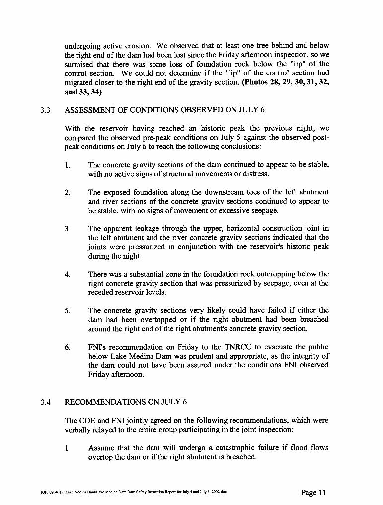
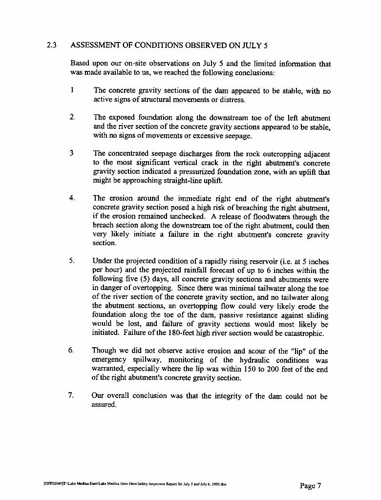
undergoing active erosion. We observed that at least one tree behind and belowthe right end of the danl had been lost since the Friday afternoon inspection, so wesunnised that there was some loss of foundation rock below the "lip" of thecontrol section. We could not determine if the "lip" of the control section hadmigrated closer to the right end of the gravity section. (Photos 28, 29, 30, 31, 32,and 33, 34)
ASSESSMENT OF CONDITIONS OBSERVED ON JUL Y 63.3
With the reservoir having reached an historic peak the previous night, wecompared the observed pre-peak conditions on July 5 against the observed post-peak conditions on July 6 to reach the following conclusions:
The concrete gravity sections of the dam continued to appear to be stable,with no active signs of structural movements or distress.
I.
2. The exposed foundation along the downstream toes of the left abutmentand river sections of the concrete gravity sections continued to appear tobe stable, with no signs of movement or excessive seepage.
The apparent leakage through the upper, horizontal construction joint inthe left abutment and the river concrete gravity sections indicated that thejoints were pressurized in conjunction with the reservoir's historic peakduring the night.
3
There was a substantial zone in the foundation rock outcropping below theright concrete gravity section that was pressurized by seepage, even at thereceded reservoir levels.
4.
The concrete gravity sections very likely could have failed if either thedam had been overtopped or if the right abutment had been breachedaround the right end of the right abutment's concrete gravity section.
5.
FNI's recommendation on Friday to the TNRCC to evacuate the publicbelow Lake Medina Dam was prudent and appropriate, as the integrity ofthe dam could not have been assured under the conditions FNI observedFriday afternoon.
6.
RECOMMENDA TIONS ON JUL Y 63.4
The COE and FNI jointly agreed on the following recommendations, which wereverbally relayed to the entire group participating in the joint inspection:
Assume that the dam will undergo a catastrophic failure if flood flowsovertop the dam or if the right abutment is breached.
1
Page 11[OFFO2040)TlLake Medina DarnlLake Medina Dam Darn Safety Inspection Report for July 5 and July 6, 2002 doc

Do not allow flood flows to overtop the concrete gravity structures orallow the right abutment to be breached behind the right end of the rightabutment's concrete gravity section.
2.
Repair erosion damage to the right abutment behind the right end of theright abutment's concrete gravity section.
3.
Monitor any future reservoir rises so that at least a 4-hour advanceevacuation warning can be given to the public prior to the reservoirreaching the top of the dam.
4.
Perfonn a detailed dam safety inspection and assessment as soon as theemergency spillway is no longer discharging.
5.
Page 12[OFFO2040]TlLake Medina Dam\Lake Medina Darn Dam Safety Inopection Repon for July S and July 6. 2002 doc

[OFF02040]T:\Lake Medina Dam\Inspection photos.doc Page 1 of 26
Appendix A: Inspection Photographs
Photo 1 View of left abutment and crest of concrete gravity section, looking right. (Friday, July 5th)
Photo 2 View of staff gage recording stage height (perhaps over the emergency spillway crest). The gage
was located in the drawdown region upstream of the emergency spillway, as evidenced by the accelerated approaching flow and resulting standing wave around the gage. (Friday, July 5th)

[OFF02040]T:\Lake Medina Dam\Inspection photos.doc Page 2 of 26
Photo 3 View of vertical crack in concrete gravity section-left abutment, looking right and downstream. Note the new leakage through the crack versus older, algae-stained leakage areas. (Friday, July 5th)
Photo 4 View of concrete gravity section-river, looking left and downstream. Note the tailwater level is
just below the inspection gallery portal, which is obstructed by vegetation. (Friday, July 5th)
New leakage
Old leakage
Inspection gallery portal
DOWNSTREAM

[OFF02040]T:\Lake Medina Dam\Inspection photos.doc Page 3 of 26
Photo 5 View of a vertical crack in the concrete gravity section-river, looking downstream. Note the new leakage through the crack versus older, algae-stained leakage areas. (Friday, July 5th)
Toe of dam
New leakage
Old leakage
DOWNSTREAM

[OFF02040]T:\Lake Medina Dam\Inspection photos.doc Page 4 of 26
Photo 6 View of a vertical crack in the concrete gravity section-river, looking downstream. Note the new leakage through the crack versus older, algae-stained leakage areas. (Friday, July 5th)
DOWNSTREAM Toe of dam
Old leakage
New leakage
Inspection gallery portal

[OFF02040]T:\Lake Medina Dam\Inspection photos.doc Page 5 of 26
Photo 7 View of outlet works at the left end of the concrete gravity section-river, looking left and
downstream. Note the valve on the right is discharging uncontrolled flow out the side of the valve housing. (Friday, July 5th)
DOWNSTREAM
Inoperational outlet valve
Leakage from valve housing

[OFF02040]T:\Lake Medina Dam\Inspection photos.doc Page 6 of 26
Photo 8 View of accumulated flow along toe of concrete gravity section-right abutment, looking downstream. (Friday, July 5th)
Photo 9 View of foundation seepage downstream of toe of dam, looking right and downstream. (Friday, July 5th)
Toe of dam
Flow concentrations
DOWNSTREAM
DOWNSTREAM
Toe of dam
Foundation seepage

[OFF02040]T:\Lake Medina Dam\Inspection photos.doc Page 7 of 26
Photo 10 View of vertical crack in concrete gravity section-right abutment, looking right. Note the pressurized leakage exiting the crack several feet above the old, algae-stained leakage area. (Friday, July 5th)
DOWNSTREAM
New, pressurized leakage
Old leakage
Toe of dam

[OFF02040]T:\Lake Medina Dam\Inspection photos.doc Page 8 of 26
Photo 11 View of vertical crack in concrete gravity section-right abutment, looking downstream. Note the pressurized leakage exiting the crack several feet above the old, algae-stained leakage area. (Friday, July 5th)
DOWNSTREAM
Toe of dam Old leakage
New, pressurized leakage

[OFF02040]T:\Lake Medina Dam\Inspection photos.doc Page 9 of 26
Photo 12 View of erosion along right abutment, looking left. Note the standing waves along the abutment. (Friday, July 5th)
DOWNSTREAM
Staff gage
FLOW
Right abutment

[OFF02040]T:\Lake Medina Dam\Inspection photos.doc Page 10 of 26
Photo 13 View of right abutment, looking right. Note the erosion along the abutment (see Photo 12) in the background. (Friday, July 5th)
Standing waves
FLOW
Upstream face of dam
DOWNSTREAM
“Lip” of emergency spillway

[OFF02040]T:\Lake Medina Dam\Inspection photos.doc Page 11 of 26
Photo 14 View of erosion along right abutment, looking right. Note the standing waves along the abutment. (Friday, July 5th)
Photo 15 View of overtopping and erosion of left overbank, looking left. (Friday, July 5th)
DOWNSTREAM
FLOW
“Lip” of emergency spillway
FLOW
DOWNSTREAM

[OFF02040]T:\Lake Medina Dam\Inspection photos.doc Page 12 of 26
Photo 16 View of discharge over emergency spillway, looking upstream from the right abutment. Note
the turbulent flow and standing waves approaching the spillway “lip”. (Friday, July 5th)
Photo 17 View of discharge over emergency spillway, looking upstream from the left overbank. Note the
overtopping of the left overbank in the foreground. (Friday, July 5th)
FLOW
FLOW

[OFF02040]T:\Lake Medina Dam\Inspection photos.doc Page 13 of 26
Photo 18 View of the emergency spillway, looking upstream from the right abutment. Note the concave
alignment of the spillway lip and its apex at the near the midpoint. (Friday, July 5th)
Photo 19 View of side channel, looking from left overbank. Note the newly eroded pocket in the opposite
bank. (Friday, July 5th)
Spillway apex
FLOW
FLOW
Match Photo 20
Match Photo 20
Eroded pocket

[OFF02040]T:\Lake Medina Dam\Inspection photos.doc Page 14 of 26
Photo 20 View of side channel, looking from left overbank. (Friday, July 5th)
Photo 21 View of staff gage, looking right. (Saturday, July 6th)
Match Photo 19
Match Photo 19
“Lip” of emergency spillway
FLOW
FLOW
DOWNSTREAM

[OFF02040]T:\Lake Medina Dam\Inspection photos.doc Page 15 of 26
Photo 22 View of concrete gravity section-left abutment, looking right. Note the dampened section along a horizontal line. (Saturday, July 6th)
DOWNSTREAM
Toe of dam

[OFF02040]T:\Lake Medina Dam\Inspection photos.doc Page 16 of 26
Photo 23 View of concrete gravity section-river, looking right. Note the dampened section along a horizontal line. (Saturday, July 6th)
Toe of dam
DOWNSTREAM

[OFF02040]T:\Lake Medina Dam\Inspection photos.doc Page 17 of 26
Photo 24 View of concrete gravity section-river, looking left and downstream. Note the tailwater level is just below the inspection gallery portal. (Saturday, July 6th)
Inspection gallery portal

[OFF02040]T:\Lake Medina Dam\Inspection photos.doc Page 18 of 26
Photo 25 View of foundation seepage downstream of toe of dam, looking right. (Saturday, July 6th)
DOWNSTREAM
Seepage exit point Seepage exit point

[OFF02040]T:\Lake Medina Dam\Inspection photos.doc Page 19 of 26
Photo 26 View of foundation seepage downstream of the dam. (Saturday, July 6th)
DOWNSTREAM
Seepage exit point
Seepage exit point

[OFF02040]T:\Lake Medina Dam\Inspection photos.doc Page 20 of 26
Photo 27 View of erosion along right abutment, looking right. (Saturday, July 6th)
DOWNSTREAM
FLOW
Right abutment

[OFF02040]T:\Lake Medina Dam\Inspection photos.doc Page 21 of 26
Photo 28 Panoramic view of emergency spillway, looking right. (Saturday, July 6th)
Match Photo 29
Match Photo 29
FLOW
Right abutment
[OFF02040]T:\Lake Medina Dam\Inspection photos.doc Page 22 of 26
Photo 29 Panoramic view of emergency spillway, looking right. (Saturday, July 6th)
Match Photo 30
Match Photo 30
Match Photo 28
Match Photo 28
FLOW

[OFF02040]T:\Lake Medina Dam\Inspection photos.doc Page 23 of 26
Photo 30 Panoramic view of emergency spillway, looking right. (Saturday, July 6th)
Match Photo 31
Match Photo 31
Match Photo 29
Match Photo 29
FLOW
[OFF02040]T:\Lake Medina Dam\Inspection photos.doc Page 24 of 26
Photo 31 Panoramic view of emergency spillway, looking right. (Saturday, July 6th)
Match Photo 32
Match Photo 32
Match Photo 30
Match Photo 30
FLOW

[OFF02040]T:\Lake Medina Dam\Inspection photos.doc Page 25 of 26
Photo 32 Panoramic view of emergency spillway, looking right. (Saturday, July 6th)
Match Photo 33
Match Photo 33
Match Photo 31
Match Photo 31
FLOW
[OFF02040]T:\Lake Medina Dam\Inspection photos.doc Page 26 of 26
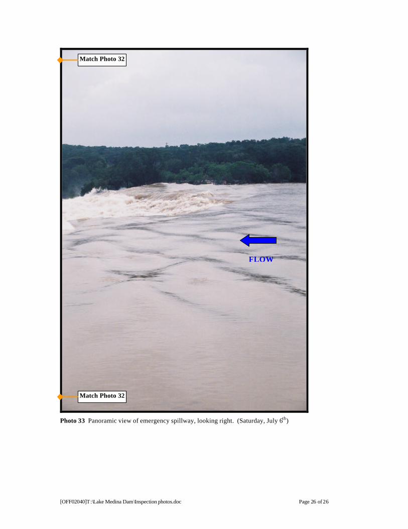
Photo 33 Panoramic view of emergency spillway, looking right. (Saturday, July 6th)
Match Photo 32
Match Photo 32
FLOW

![[PPT]Vulernability map of the Edwards Aquifer - University of … · Web viewVulnerability map of the Edwards Aquifer Aquifer DRASTIC INDEX 84 - 90 90 - 978 97 - 104 104 – 111 111](https://static.fdocuments.in/doc/165x107/5aebf7d37f8b9ab24d8f7734/pptvulernability-map-of-the-edwards-aquifer-university-of-viewvulnerability.jpg)