Lab Manual For Software Engineering - Datta Meghe...
53
Software Engineering-Lab Manual DATTA MEGHE COLLEGE OF ENGINEERING Department of Information Technology Lab Manual For Software Engineering Semester Jan 2016-April 2016 Page 1
Transcript of Lab Manual For Software Engineering - Datta Meghe...

Software Engineering-Lab Manual
DATTA MEGHE COLLEGE OF ENGINEERING
Department of Information Technology
Lab Manual
For
Software Engineering
Semester Jan 2016-April 2016
Page 1
Software Engineering-Lab Manual
CONTENTS
Page No.
1. Objectives SE Lab 4
2. Leaning on the Successful Completion of the Lab 5
3. Schedule For Different Documents Submission 6
4. Case Study: 8
Library system
Lab Assignment based on the Case Study
i. Lab Exercise 1 9
ii. Lab Exercise 2 9
iii. Lab Exercise 3 10
iv. Lab Exercise 4 10
v. Lab Exercise 5 10
5. Case Studies: Problem Statements 12
i) ATM System 13
ii) Clinic Management System 15
iii) Student Information System 16
iv) Warehouse Management System 17
v) School Bus Operation 19
vi) Recycling System 20
6. Format for the deliverables 21
i) Use Case Specification Document 22
ii) Class Analysis Document 26
iii) Sequence Diagram Document 27
Page 2
Software Engineering-Lab Manual
iv) Collaboration Diagram Document 28
v) Class Diagram Document 29
7. Tutorial on Rational Rose 30
Page 3

Software Engineering-Lab Manual
Objectives: Software Engineering Lab
The Software Engineering Lab provides a deep insight into the importance
of requirement modeling in the software industry. It will enable us to learn
the Rational Rose tool employed in the software development life cycle,
which makes the process of requirement modeling easy to understand and
implement.
Requirements modeling is an information technology for making it easier to
capture, communicate, track, analyze, verify, validate, view, and manage the
hundreds of hierarchical and interrelated engineering requirements necessary
for large and/or complex systems. It will significantly reduce the cost of
systems development and will reduce the probability and severity of cost and
schedule growth (overruns) by enabling the description of human readable
and “computer friendly”, specifications of a system’s engineering
requirements.
Rational Rose is the tool which will be used for the requirement modeling. It
gives us the environment where the entire process of development can be
specified to its minutest detail. It gives us the facility to design our front-end
process as well as our database structure.
Application Tools
Rational Rose
Page 4
Software Engineering-Lab Manual
Learning on the successful completion of the course
Rose:
1. The students shall be able to analyze and design their project.
2. The students should be able to identify the analysis elements of the
project and understand the association between them.
3. They will be able to create analysis model of their project.
4. The entire database structure together with generation of schemas,
tables, stored procedures etc. till the generation of the executable
script can be designed and created by the students.
Page 5
Software Engineering-Lab Manual
Guidelines for the students:
1. The students will work individually under the guidance of the
faculty.
2. They should have at least one meeting in a week with the faculty
for the assessment of their work progress.
3. The students should meet the faculty with the formal documents
and proper presentations prepared of their work till date.
4. Every student should always be prepared for a viva-voice or
presentation of his or her work.
5. Regularity and sincerity will be taken into consideration while
evaluating the students.
Please note that Analysis and Design follows an iterative approach.
Therefore, solving the Lab Exercises and the Case Studies will follow a series of iterations to evolve into the Final System
Page 7

Software Engineering-Lab Manual
CASE STUDY
Library System
The Informatics students and Faculty use the Library System. The Library contains
Books and Journals. Books can be issued to both the Students and Faculty. Journals can
only be issued to the Faculty. The Librarian can only issue books and Journals. The
deputy-Librarian is In-charge of receiving the Returned Books and Journals. Each student
is provided with three Library cards for using the facilities of the Library. Students can be
issued only three books on their available cards at a time. On the issue of the books the
Librarian specifies a date on which the students are expected to return the book. In case
they are unable to do so, they will be charged with a fine of Rs 2 per day. The Accountant
is responsible for receiving the fine for over-due books.
Each Faculty is provided with a Library member ID. Faculties can be issued a maximum
of five books at a time. The issue of Journals and Books to the Faculties is also performed
in the same manner. Faculties are not charged with any fine.
Page 8
Software Engineering-Lab Manual
Lab Assignments
EXERCISE 1:
Identify and create Use cases for the problem statement.
Identify and create the Actors for the problem statement.
Objective:
To understand the problem statement and analyze it.
To understand the meaning of use cases and actors.
EXERCISE 2:
Define Classes in the Logical View associated with each Use Case and
define their structure
Objective:
1. To understand the different type of analysis classes for each use case.
2. To create the structure of the s/w in terms of analysis classes.
3. To understand the concept of stereotype.
Page 9
Software Engineering-Lab Manual
EXERCISE 3:
Draw sequence diagram for each Use Case identified in the
problem statement.
Objective:
To understand how different objects are interacting with each other.
To understand which event occurs first, and what happens next.
To understand the operations of the classes.
EXERCISE 4:
Draw the collaboration diagram for the problem statement.
Objective:
To understand the difference b/w sequence diagram and collaboration
diagram
To learn what notations and symbols are used in a collaboration
diagram.
Page 10
Software Engineering-Lab Manual
EXERCISE 5:
Draw the Class Diagram for the problem statement.
Objective:
Identify the entity classes.
To understand the relationships between these classes.
Identify dependency, hierarchy and associativity between these classes. Page 11
Software Engineering-Lab Manual
Additional Case Studies
i. Students have to select one case study and inform the
faculty member immediately on the starting of the
Lab Classes. ii. No request for change will be entertained subsequently
iii. Students are also advised to refrain from copying the
solutions either from internet, print material or from
fellow colleague
Page 12
Software Engineering-Lab Manual
Automatic Teller Machine (ATM) The software to be designed will control a simulated automated teller machine (ATM) having a magnetic stripe reader for reading an ATM card, a customer console (keyboard and display) for interaction with the customer, a slot for depositing envelopes, a dispenser for cash (in multiples of $20), a printer for printing customer receipts, and a key-operated switch to allow an operator to start or stop the machine. The ATM will communicate with the bank's computer over an appropriate communication link. (The software on the latter is not part of the requirements for this problem.)
The ATM will service one customer at a time. A customer will be required to insert an ATM card and enter a personal identification number (PIN) - both of which will be sent to the bank for validation as part of each transaction. The customer will then be able to perform one or more transactions. The card will be retained in the machine until the customer indicates that he/she desires no further transactions, at which point it will be returned - except as noted below.
The ATM must be able to provide the following services to the customer:
1. A customer must be able to make a cash withdrawal from any suitable account
linked to the card, in multiples of $20.00. Approval must be obtained from the bank before cash is dispensed.
2. A customer must be able to make a deposit to any account linked to the card, consisting of cash and/or checks in an envelope. The customer will enter the amount of the deposit into the ATM, subject to manual verification when the envelope is removed from the machine by an operator. Approval must be obtained from the bank before physically accepting the envelope.
3. A customer must be able to make a transfer of money between any two accounts linked to the card.
4. A customer must be able to make a balance inquiry of any account linked to the card.
A customer must be able to abort a transaction in progress by pressing the Cancel key instead of responding to a request from the machine.
The ATM will communicate each transaction to the bank and obtain verification that it was allowed by the bank. Ordinarily, a transaction will be considered complete by the bank once it has been approved. In the case of a deposit, a second message will be sent to the bank indicating that the customer has deposited the envelope. (If the customer fails to deposit the envelope within the timeout period, or presses cancel instead, no second message will be sent to the bank and the deposit will not be credited to the customer.)
If the bank determines that the customer's PIN is invalid, the customer will be required to re-enter the PIN before a transaction can proceed. If the customer is unable to
Page 13

Software Engineering-Lab Manual successfully enter the PIN after three tries, the card will be permanently retained by the machine, and the customer will have to contact the bank to get it back.
If a transaction fails for any reason other than an invalid PIN, the ATM will display an explanation of the problem, and will then ask the customer whether he/she wants to do another transaction.
The ATM will provide the customer with a printed receipt for each successful transaction, showing the date, time, machine location, type of transaction, account(s), amount, and ending and available balance(s) of the affected account ("to" account for transfers).
The ATM will have a key-operated switch that will allow an operator to start and stop the servicing of customers. After turning the switch to the "on" position, the operator will be required to verify and enter the total cash on hand. The machine can only be turned off when it is not servicing a customer. When the switch is moved to the "off" position, the machine will shut down, so that the operator may remove deposit envelopes and reload the machine with cash, blank receipts, etc.
The ATM will also maintain an internal log of transactions to facilitate resolving ambiguities arising from a hardware failure in the middle of a transaction. Entries will be made in the log when the ATM is started up and shut down, for each message sent to the Bank (along with the response back, if one is expected), for the dispensing of cash, and for the receiving of an envelope. Log entries may contain card numbers and dollar amounts, but for security will never contain a PIN. Page 14

Software Engineering-Lab Manual
Clinic Management System
There is a Clinic Management system. An assistant of the doctor and the doctor himself
uses the system. The system keeps information about all the patients visiting the clinic.
Each patient is charged a fee of Rs 100 on his visit to the clinic. If the patient revisits the
clinic within 5 days he is not charged any fees but after that he is charged again. The
clinic also provides the facility of medicines which is optional for the patients to take.
Each patient is provided with a prescription and receipt on his each visit. The system
stores the following info:
Personal data about each patient visiting the clinic.
The different medicines available in the store with their manufacturing date
and expiry date.
Also information like the company which is manufacturing that medicine,
etc.,
Information like who are all the patients who have got treatment from that
clinic and against what disease.
Page 15
Software Engineering-Lab Manual
Student Information System
An information system has to be created which stores the detail information about
various students in different semesters of the MBA course. The system stores information
like:
Which student is in which semester
The result of each student for each semester
Fee details of the course
Attendance of each student in each semester.
Page 16
Software Engineering-Lab Manual
Warehouse Management System
The system will support warehouse management. The company ordering the system,
ACME warehouse Management Inc, specializes in supporting its customer with
warehouses places all over the nation. Examples of customer are companies that need
space to store their products before they are shipped or companies that need local
warehouses without having local offices. ACME is already a specialist in storing
different kinds of items and in the use of trucks to redistribute the items.
ACME plans to grow and now needs an information system with which they can grow.
The idea is to offer the customers warehouse space and redistribute services between
different warehouses with full computer support. The service includes redistribution both
within a warehouse and between warehouses, all dictated by customer needs. All kinds of
items may be stored in the warehouses., Which means that it is important to differentiate
between certain kinds of items; for example some items must not come into contact with
other items ( such as industrial chemicals and foods.)
The following people will be using the system in some way or another
Foreman responsible for one warehouse;
Warehouse worker works in a warehouse, loading and unloading;
Truck driver drives a truck between different warehouses;
Forklift operator drives a forklift in one warehouse;
Office personnel Receives orders and requests from customers
Customers Own the items in the warehouses and give instructions as to where and
when they want the items.
It is fundamental to the ACME system that it should be as decentralized, as possible and
that all persons involved should be reachable at all times. Therefore the truck drivers
should have communication devices for getting their orders and they must be able to
communicate with the foreman or the office. This means that we also need a radio
communication network a system that should not be developed by us but bought Page 17

Software Engineering-Lab Manual
separately. The warehouse workers loading and unloading should use a barcode reader
when handling the items in order to be as efficient as possible. This means all items must
be marked when inserted in the warehouse system by a warehouse worker. This marking
must at the same time giver information about the item to the information system. The
foreman should be able to work several items at the same time, so they will probably
need a window based terminal. They are responsible for effecting the redistribution
orders from the office. When the customer wants to do something with his items, he will contact the office ,
which in turn submits redistribution orders to the system. Eventually if the system is to
work well, ACME plans to give their customers terminals so that they can interact
directly with the system.
Page 18
Software Engineering-Lab Manual
School Bus Operation
A New Branch School District operates a fleet of 40 buses that serve approximately
1,000 students in grades 1 to 12. The bus operation involves 30 regular routes, plus
special routes for activities, athletic events, and summer sessions. The district employs 12
full time drivers and 25 to 30 part-time drivers. A dispatcher coordinates the staffing and
routes and relays messages to drivers regarding students and parents who call about
pickup and drop-off arrangements. The System stores information like:
Personal info of each student using the facility
Information regarding each bus run by the school
Personal info of Bus Employees
Information like which bus is running on which route, which students are using
the services of which bus. etc.,
Page 19

Software Engineering-Lab Manual
Recycling Machine
A system controls a recycling machine for returnable bottles, canes and crates. The
machine can be used by several customers at the same time and each customer can return
all three types of items on the same occasion. Since there may be different types and sizes
of bottles and canes, the system has to check for each item, what type has been returned.
The system will register how many items each customer returns and, when the customer
asks for a receipt, the system will print out what he or she has deposited, the value of
returned items and the total return sum that will be paid to the customer.
The system is also used by an operator. The operator wants to know how many items of
each type have been returned during the day. At the end of the day, the operator asks for a
printout of a total number of items that have been deposited in the machine on that
particular day. The operator should also be able to change information in the system such
as the deposit values of items. If there is something a miss, for instance, if a can get
struck or if the receipt role is finished , the operator will be called by a special alarm
signal.
Page 20

Software Engineering-Lab Manual
Format For The
Deliverables Page 21

Software Engineering-Lab Manual
Use Case Specification : <Use-Case Name>
1. Use Case Name
1.1 Brief Description
[ The description should briefly convey the role and purpose of the
use case. A single paragraph should suffice for this description.]
2. Flow of Events
2.1 Basic Flow
[ This use case starts when the actor does something. An actor
always initiates use Cases. The use case should describe what the
actor does and what the system does in response. It should be
phrased in the form of a dialog between the actor and the system.
The use case should describe what happens inside the system, but
not how or why. If information is exchanged be specific about what
is passed back and forth. For example, it is not very illuminating to
say that the Actor enters customer information; it is better to say the
Actor enters the customer’s name and address. A Glossary of Terms
is often useful to keep the complexity of the use case manageable;
you may want to define things like customer information there, to
keep the use case from drowning in details.
Page 22

Software Engineering-Lab Manual
Simple alternatives may be presented within the text of the use case.
If it only takes a few sentences to describe what happens when there
is an alternative; do it directly within the flow of events section. If
the alternative flows are more complex, use a separate section to
describe it. For example An Alternative Flow describes how to
describe more complex alternatives.
A picture is sometimes worth a thousand words (though there is no
substitute for clean, clear prose). If it improves clarity, feel free to
paste graphical depictions of user interfaces, process flows, or other
figures into the use case to improve its clarity. If a flow chart is
useful to present a complex decision process, by all means use it!
Similarly for state-dependent behavior, a state-transition diagram
often clarifies the behavior of a system better than pages upon pages
of text. Use the right presentation medium for your problem, but be
wary of using terminology, notation or figures that your audience
may not understand. Remember that your purpose is to clarify, not
obscure.]
2.2 Alternative Flows
2.2.1 < First Alternative Flow>
[More complex alternatives should be described in a separate
section, which is referred to in the basic flow of events section.
Think of the alternative flow sections like alternative behavior –
Page 23
Software Engineering-Lab Manual
each alternative flow represents alternative behavior (many times,
because of exceptions that occur in the main flow). They may be as
long as necessary to describe the events associated with the
alternative behavior. When an alternative flow ends, the events of
the main flow of events are resumed unless otherwise stated.]
2.2.1.1 <An Alternative sub-flow>
[Alternative flows may in turn be broken down into sub-sections if it
improves clarity.]
2.2.2 <Second Alternative Flow>
[There may be, and most likely will be, a number of alternative flows
in a use case. Keep each alternative separate to improve clarity.
Using alternative flows improves the readability of the use case, as
well as preventing use cases from being decomposed into hierarchies
of use cases. Keep in mind that use cases are just textual descriptions,
and their main purpose is to document the behavior of a system in a
clear, concise and understandable way.]
3. Special Requirements
[A Special Requirement is typically a non-functional requirement that
is specific to a use case but is not easily or naturally specified in the
text of the use case’s event flow. Examples of special requirements
include legal and regulatory requirements, application standards, and Page 24
Software Engineering-Lab Manual
quality attributes of the system to be built, including usability,
reliability, performance or supportability requirements. Additionally,
other requirements such as operating systems and environments,
compatibility requirements, and design constraints should be captured
in this section.]
3.1 <First special requirement>
4. Preconditions
[A precondition (of a use case) is the state of the system that must be
present prior to a use case being performed.]
4.1 <Precondition One>
5. Post Conditions
[A post condition (of a use case) is a list of possible states the system
can be in immediately after a use case has finished.]
5.1 <Post condition one>
6. Extension Points
[Extension points of the use case.]
6.1 <Name of extension point>
[Definition of the location of the extension point in the flow of events.] Page 25

Software Engineering-Lab Manual
Class Analysis Document
The class analysis document should contain the following information:
A brief description on what does one understand by Class Analysis
A brief description on types of Analysis Classes.
Identify all the Analysis Classes for your problem statement
and briefly describe their purpose. Page 26

Software Engineering-Lab Manual
Sequence Diagram Document
The Sequence Diagram Document should contain the following information:
A sequence diagram for each Use case of your system.
A brief description on the symbols used in the sequence diagram
explaining the reason for the usage of that particular symbol.
A brief description on the flow of each event in each
sequence diagram. Page 27
Software Engineering-Lab Manual
Collaboration Diagram Document
The Collaboration Diagram Document should contain the following
information:
A collaboration diagram for each Use case of your system.
A brief description on the symbols used in the collaboration diagram
explaining the reason for the usage of that particular symbol.
A brief description on the flow of each event in each
collaboration diagram.
Page 28

Software Engineering-Lab Manual
Class Diagram Document
The Class Diagram Document should contain the following information:
A Class diagram for each Use case of your system.
A brief description on the symbols used in the Class diagram
explaining the reason for the usage of that particular symbol.
A brief description on the flow of each event in each Class diagram. Page 29
Software Engineering-Lab Manual
Tutorial on Rational Rose
Analysis and Design Methodology
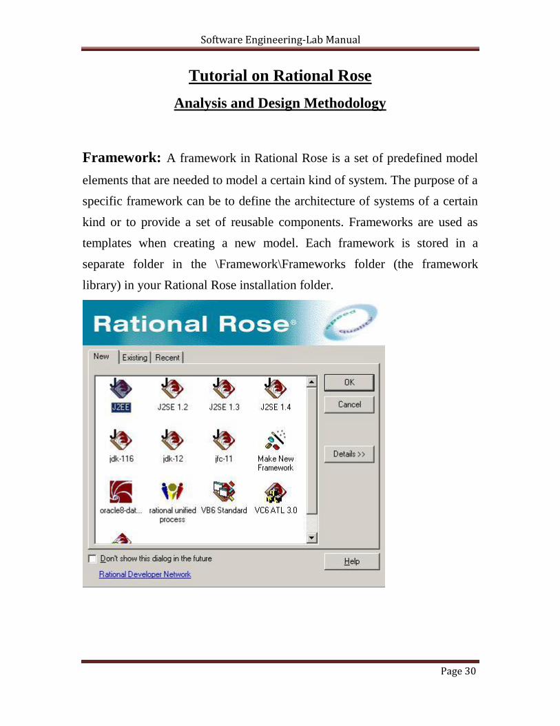
Framework: A framework in Rational Rose is a set of predefined model
elements that are needed to model a certain kind of system. The purpose of a
specific framework can be to define the architecture of systems of a certain
kind or to provide a set of reusable components. Frameworks are used as
templates when creating a new model. Each framework is stored in a
separate folder in the \Framework\Frameworks folder (the framework
library) in your Rational Rose installation folder.
Page 30

Software Engineering-Lab Manual
Use Case Diagram : Depicts interaction between Actors and Use Cases.
Use Case: A use case is a sequence of actions a system performs that
yields an observable result of value to a particular actor.
Actor: An actor represents many things that interact with the system.
Stereotype: Representing one model element in the form of another
model element.
Classes are stereotyped depending on the following categories: Page 31
Software Engineering-Lab Manual
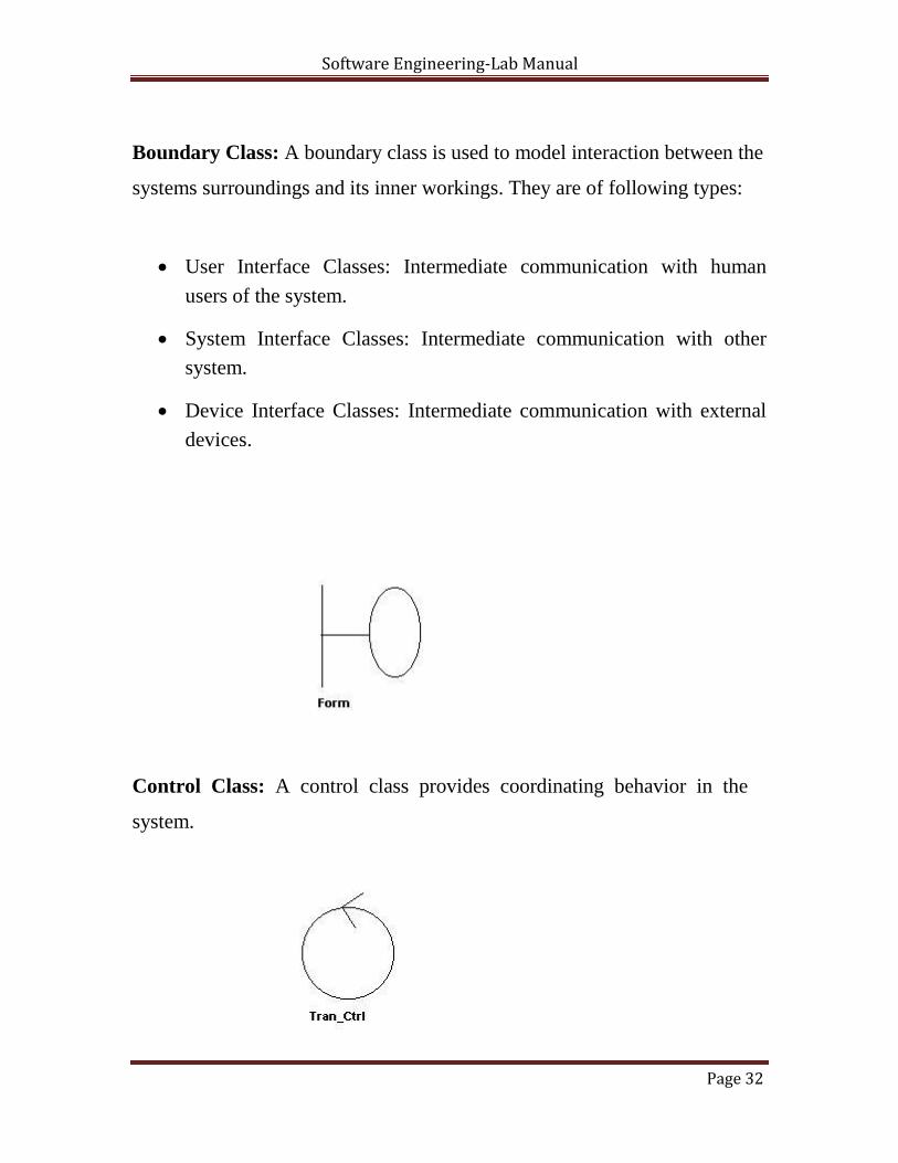
Boundary Class: A boundary class is used to model interaction between the
systems surroundings and its inner workings. They are of following types:
User Interface Classes: Intermediate communication with human
users of the system.
System Interface Classes: Intermediate communication with other
system.
Device Interface Classes: Intermediate communication with external
devices.
Control Class: A control class provides coordinating behavior in the
system.
Page 32
Software Engineering-Lab Manual
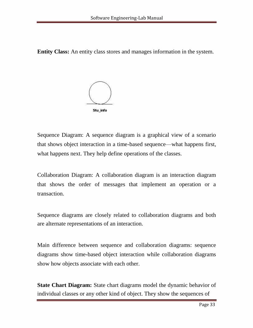
Entity Class: An entity class stores and manages information in the system.
Sequence Diagram: A sequence diagram is a graphical view of a scenario
that shows object interaction in a time-based sequence—what happens first,
what happens next. They help define operations of the classes.
Collaboration Diagram: A collaboration diagram is an interaction diagram
that shows the order of messages that implement an operation or a
transaction.
Sequence diagrams are closely related to collaboration diagrams and both
are alternate representations of an interaction.
Main difference between sequence and collaboration diagrams: sequence
diagrams show time-based object interaction while collaboration diagrams
show how objects associate with each other.
State Chart Diagram: State chart diagrams model the dynamic behavior of
individual classes or any other kind of object. They show the sequences of Page 33
Software Engineering-Lab Manual
states that an object goes through, the events that cause a transition from one
state to another, and the actions that result from a state change.
Activity Diagram: An activity diagram is basically a special case of a state
machine in which most of the states are activities and most of the transitions
are implicitly triggered by completion of the actions in the source activities.
Object Model Diagram: The object model is built and graphically
represented in the Class Diagram. You can use an object model for two
purposes. First, you can use the object model as an application object model.
An application object model captures a conceptual view of the application
and can be assigned to a component language like Java, Visual Basic, or
Analysis.
Second, you can use the object model as a logical data model. A logical data
model captures a conceptual view of a database. You can use the Analysis
language as the component language if you want to create a database-
independent logical data model. However, to implement the model you are
required to transform it to a data model and assign it to a supported DBMS.
Regardless of its purpose, you design an object model by creating Logical
View packages. Each package must contain persistent classes with attributes
assigned to the classes. The classes relate to one another by associations or
aggregations. You add roles and multiplicity to provide additional context to
your associations and model design. Object models use UML terminology
and notation to express a complete model. Elements in an object model map
to elements in a data model. Page 34

Software Engineering-Lab Manual
Data Model Diagram: Data Model Diagrams use the UML profile notation
for representing data model entities. When you have an existing data model,
you can drag-and drop data model elements from the browser to the Data
Model Diagram or you can use the Add Tables sub-menu on the Query
menu to populate the diagram. When you are creating a new data model, you
can use the toolbox or the Create sub-menu on the Tools menu to create data
model elements in the Data Model Diagram.
Object Model Elements Data Model Elements
Class Table
Operation Constraint
Attribute Column
Package Schema
Component Database
Association or Aggregation Non-Identifying Relationship
Composite Aggregation Identifying Relationship
Role Role
Multiplicity Cardinality
Page 35

Software Engineering-Lab Manual
Creating Use Cases
Creating Actors in Rational Rose
Right-click on the Use Case View package in the browser to make the shortcut
menu visible. Select the New: Actor menu option. A new actor called New Class is placed in
the browser. With the actor called New Class selected, enter the desired name of the actor.
Documenting Actors in Rational Rose 1. If the documentation window is not visible, open the documentation window
by selecting the Documentation menu choice from the View menu. 2. Click to select the actor in the browser. 3. Position the cursor in the documentation window and enter the
documentation.
Creating Use Cases in Rational Rose Right-click on the Use Case View in the browser to make the shortcut menu
visible. Select the New: Use Case menu option. A new unnamed use case is placed in
the browser. With the use case selected, enter the desired name of the use case.
Page 36
Software Engineering-Lab Manual
Creating a Use Case brief Description in Rational Rose
1. Click to select the use case in the browser. 2. Position the cursor in the documentation window and enter the brief
description for the use case. If the documentation window is not visible, select
the View: Documentation menu choice to make the window visible.
Linking Flow of Events Documents to use cases in Rational Rose
1. Right-click on the use case in the browser to make the shortcut menu visible. 2. Select the Open Specification menu option. 3. Select the Files tab. 4. Right-click to make the shortcut menu visible. 5. Select the Insert File menu option. 6. Browse to the appropriate directory and select the desired file. 7. Click the Open button 8. Click the OK button to close the specification
Creating the main use case Diagram in Rational Rose 1. Double-click on the Main diagram in the Use Case View in the browser to
open the diagram. 2. Click to select an actor in the browser and drag the actor onto the diagram. 3. Repeat step 2 for each additional actor needed in the diagram 4. Click to select a use case in the browser and drag the use case onto the
diagram. 5. Repeat step 4 for each additional use case needed in the diagram.
Page 37
Software Engineering-Lab Manual
Note: Actors and use cases may also be created directly on a use case
diagram by using the toolbar.
Creating Communicate Associations in Rational Rose 1. Click to select the Association icon or the Unidirectional Association icon from
the diagram toolbar. Note: If the Association icon is not present on the
toolbar, it may be added by right-clicking on the toolbar, selecting the
Customize menu choice from the shortcut menu, and adding the icon to the
toolbar. 2. Click on an actor initiating a communication and drag the association line to
the desired use case.
To add the communicate stereotype (optional): 1. Double-click on the association line to make the Specification visible. 2. Click the arrow in the Stereotype field to make the drop-down menu visible,
and select communicate. 3. Click the OK button to close the Specification. 4. Repeat the preceding steps for each additional communicate relationship.
Creating Include Relationships in Rational Rose
1. Click to select the Dependency icon from the toolbar. 2. Click on the base use case and drag the Dependency icon to the used use
case. 3. Double-click on the dependency arrow to make the Specification visible. 4. Click the arrow in the Stereotype filed to make the drop-down menu visible,
and select include.
Page 38

Software Engineering-Lab Manual 5. Click the OK button to close the Specification.
Creating Extend Relationships in Rational Rose
1. Click to select the Dependency icon from the toolbar. 2. Click on the use case containing the extended functionality and drag the
Dependency icon to the base use case. 3. Double-click on the dependency arrow to make the Specification visible. 4. Click the arrow in the Stereotype field to make the drop-down menu visible
and select extend. 5. Click the OK button to close the Specification.
Creating Additional Use Case Diagrams in Rational Rose 1. Right-click on the Use Case View in the browser to make the shortcut menu
visible. 2. Select the New: Use Case Diagram menu option. 3. While the use case diagram is selected, enter the name of the actor. 4. Open the diagram and add actors, use cases, and interactions to the diagram
as needed.
Creating Activity Diagrams in Rational Rose
1. Right-click on the Use Case View in the browser to make the shortcut
menu visible.
Page 39
Software Engineering-Lab Manual
2. Select the New: Activity Diagram menu choice. This will add an activity
diagram called New Diagram to the browser. 3. While the new diagram is still selected, enter the name of the diagram. 4. Double-click on the activity diagram in the browser to open the diagram.
Creating Activities in Rational Rose
1. Click to select the Activity icon from the toolbar. 2. Click on the activity diagram window to place the activity. 3. While the activity is still selected, enter the name of the activity.
Creating Transitions in Rational Rose
Click to select the state transition icon from the toolbar. Click on the originating activity and drag the transition arrow to the successor
activity.
Creating Decision Points in Rational Rose
Click to select the Decision icon from the toolbar. Click on the activity diagram window to place the decision. While the decision is still selected, enter the name of the
decision. Click to select the Transition icon the toolbar. Click on the originating activity and drag the transition to the decision icon. Page 40
Software Engineering-Lab Manual
Creating Guarded Transitions in Rational Rose
Click to select the State Transition icon from the toolbar. Click on the decision and drag the transition to the successor activity. (Note:
Rational Rose may place the transition on top of an existing transition. To
separate the transition, select the transition and drag it onto the activity
diagram window.) Double-click on the transition arrow to make the Specification visible.
Select the Detail tab.
Enter the guard condition in the Guard Condition
field. Click the OK button to close the Specification.
Creating Rectilinear Lines in Rational Rose Click to select the line that should be rectilinear (multi-select may be
accomplished by first selecting the Shift button). Select the Format: Line Style: Rectilinear menu choice.
Relocate the lines as needed by selecting the line and dragging it to the desired
location on the activity diagram window.
Creating Synchronization Bars in Rational Rose Click to select the Horizontal Synchronization or the Vertical Synchronization icon
from the toolbar. Click on the activity diagram window to place the synchronization bar.
Page 41
Software Engineering-Lab Manual
Click to select the State Transition icon on the toolbar and add any needed
incoming the outgoing transitions to the synchronization bar.
Creating Swimlanes in Rational Rose
Click to select the Swimlane icon from the toolbar.
Click on the activity diagram window to place the swimlane. This will add a
swimlane called NewSwimlane to the diagram. Double-click on the NewSwimlane (the words) to open the Specification.
Enter the name of the swimlane in the Name filed. Click the OK button to close the Specification.
To resize the swimlane, click on the swimlane border and drag the swimlane to
the desired location. Drag all needed activities and transitions into the swimlane, (Note: You may also
create new activities and transitions in the swimlane.)
Creating Starting and Ending Activities in Rational Rose Click to select the Start State or the End State icon from the toolbar.
Click on the activity diagram window to place the start or end state.
If you added a start state, click on the state Transition icon, click on the start
state, and drag the transitions to the first activity in the workflow. If you added an end state, click on the State Transition icon, click on the
successor activity, and drag the transition to the end state.
Page 42
Software Engineering-Lab Manual
Finding Classes
Creating Classes in the Rose Browser
Right-click to select the Logical View in the browser.
Select the New: Class menu choice. A class called New Class is placed in
the browser.
While the new class is still selected, enter the name of the class.
Creating Stereotypes for Classes in Rational Rose
Right-click to select the class in the browser and make the shortcut menu
visible.
Select the Open Specification menu
choice. Select the General tab.
Click the arrow in the Stereotype field to make the drop-down menu visible
and select the desired stereotype or, to create a new stereotype, enter the
name of the stereotype in the Stereotype field.
Click the OK button to close the Specification.
Creating Packages in the Rose Browser
Right-click to select the Logical View in the
browser. Select the New: Package menu choice. While the package is still selected, enter the name of the package. Page 43

Software Engineering-Lab Manual
Relocating Classes in the Rose Browser
Click to select the class in the browser. Drag the class to the desired package. Repeat the steps for each class that is to be relocated.
The Main Class Diagram in Rational Rose Rose automatically creates the Main class diagram in the Logical View of the
model. To add packages to the Main class diagram: Double-click on the Main diagram in the browser to open the diagram. Click to select the package in the browser. Drag the package onto the diagram. Repeat the preceding steps for each package that is to be added to the diagram.
Creating a Package Main Class Diagram in Rational Rose
1. Double-click on the package on a class diagram. 2. Rose will “open” the package and create (or display) the main class diagram
for the package. 3. Click to select a class in the browser and drag the class onto the diagram.
(Note: The stereotype display of a class may be set using the Format:
Stereotype display menu choice.) 4. Repeat step 3 for each additional class that is to be placed on the diagram.
Page 44

Software Engineering-Lab Manual
To Set Visibility Display in Rational Rose
To set the default visibility display: 1. Select the Tools: Options menu choice. 2. Select the Diagram tab. 3. Select the Show Visibility checkbox to set the default to show the visibility of
all classes.
To set the visibility for a selected class: 1. Right-click to select the class on a diagram and make the shortcut menu
visible. 2. Click to select or deselect the Options: Show Visibility menu choice.
Page 45
Software Engineering-Lab Manual
Discovering Object Interaction
Creating A Logical View Use Case Diagram in Rational Rose
1. Right-click to select the Logical View package in the browser and make
the shortcut menu visible. 2. Select the New: Use Case Diagram menu choice. This will add a new use
case diagram called NewDiagram to the browser. 3. While the NewDiagram is still selected, enter the name Realizations:
Creating Use Case Realizations in Rational Rose 1. Double-click on the Realizations use case diagram in the browser to open the
diagram. 2. Click to select the Use Case icon from the toolbar. 3. Click on the use case diagram window to place the use case. This will place
the new use case on the diagram and also add it to the browser. 4. Double-click on the use case to open the Use Case Specification. 5. Enter the name of the use case (same name as the use case in the Use Case
View) in the Name field. (Note: You must enter the name in the Specification
or in the Browser to invoke Rational Rose’s namespace support. If you enter
the name on the use case diagram, Rational Rose will assume that the use
case is the same use case that is in the Use Case View.) 6. Click the arrow in the Stereotype field to make the drop-down menu visible. 7. Select use-case realization. 8. Click the OK button to close the Use Case Specification. Page 46

Software Engineering-Lab Manual
Creating A Sequence Diagram in Rational Rose
1. Right-click to select the use case realization in the Logical View of
the browser and make the shortcut menu visible. 2. Select the New: Sequence Diagram menu choice. An unnamed sequence
diagram is added to the browser. 3. With the new sequence diagram selected, enter the name of the sequence
diagram.
Page 47
Software Engineering-Lab Manual
Creating Objects and Messages in Sequence Diagrams in Rational Rose
1. Double-click on the sequence diagram in the browser to open
the diagram. 2. Click to select the actor in the browser. 3. Drag the actor onto the sequence diagram. 4. Click to select the Object icon from the toolbar. 5. Click on the sequence diagram window to place the object. 6. While the object is still selected, enter the name of the object. 7. Repeat the preceding steps for each object and actor in the scenario. 8. Click on the actor or Object Message icon from the toolbar. 9. Click on the actor or object sending the message and drag the message line
to the actor or object receiving the message. 10. While the message line is still selected, enter the name of the message. 11. Repeat steps 7 through 9 for each message in the scenario.
Assigning Objects in a Sequence Diagram to Classes in Rational Rose
1. Click to select the class in the browser. 2. Drag the class onto the object in the sequence diagram. Rose will add the
class name preceded by a colon (:) to the object name. If the object is
unnamed, the name is set to : ClassName. If the stereotype display for a
class is set to icon, and if an icon exists, then the icon will be used in the
sequence diagram.
Page 48
Software Engineering-Lab Manual
Linking Diagrams in Rational Rose
1. Select the Note icon from the toolbar. 2. Click on the diagram to place the note. 3. Select the diagram tat you wish to link in the browser and drag
the diagram onto the note. 4. To navigate to the linked diagram, double-click on the note.
Creating Collaboration Diagrams from Sequence Diagrams in Rational
Rose
1. Double-click on the sequence diagram in the browser to open
the diagram.
2. Choose the Browse: Create Collaboration Diagram menu choice or press
the F5 key. 3. Rearranging the objects and messages on the diagram as needed.
Creating a View of Participating Classes in Rational Rose
1. Right-click on the use case realization in the browser to make the
shortcut menu visible. 2. Select the New: Class Diagram menu choice. 3. While the diagram is still selected, enter the name of the class diagram. 4. Double-click on the diagram in the browser to open the diagram. 5. Click to select a class in the logical view of the browser and drag the
class onto the diagram.
Page 49

Software Engineering-Lab Manual
6. Repeat step 5 for each additional class that is to be placed onto
the diagram.
Page 50

Software Engineering-Lab Manual
Specifying Relationships
Creating an Association Relationship in Rational Rose
1. Click to select the Association icon from the toolbar. The association
icon may be added to the toolbar by right-clicking on the toolbar and
selecting the Customize menu command. 2. Click on one of the associated classes in a class diagram 3. Drag the association line to the other associated class
Creating an Aggregation Relationship in Rational Rose
1. Select the Aggregation icon from the toolbar. The Aggregation icon may
be added to the toolbar by right-clicking on the toolbar and selecting the
Customize menu command.
2. Click on the class playing the role of the “whole” in a class diagram
and drag the aggregation line to the class playing the role of the “part”.
Naming Relationships in Rational Rose
1. Click to select the relationship line on a class diagram. 2. Enter the name of the relationship.
Creating Role Names in Rational Rose
Page 51
Software Engineering-Lab Manual
1. Right-click on the relationship line near the class tat is modifies to
make the shortcut menu visible. 2. Select the Role Name menu choice. 3. Enter the name of the role.
Creating Multiplicity in Rational Rose
1. Double-click on the relationship line to make the Specification visible. 2. Select the Detail tab for the role being modified (Role A Detail or Role
B Detail). 3. Enter the desired multiplicity in the Cardinality field. 4. Click the OK button to close the Specification.
Creating a Reflexive Relationship in Rational Rose
1. Select the Association (or Aggregation) icon from the toolbar. 2. Click on the class and drag the association (or aggregation) line
outside the class. 3. Release the mouse button. 4. Click and drag the association (or aggregation) line back to the class 5. Enter the role names and multiplicity for each end of the
reflexive association (or aggregation).
Page 52

Software Engineering-Lab Manual
Creating Package Relationships in Rational Rose
1. Select the dependency relationship icon from the toolbar. 2. Click on the client package and drag the arrow to the supplier package. Page 53

Software Engineering-Lab Manual
Page 54


![SHRI DATTA MEGHE POLYTECHNIC,NAGPUR …sdmp.ac.in/DTLE/ENGLISG APPLIED GRAMMER [Read-Only].pdf · SHRI DATTA MEGHE POLYTECHNIC, ... 2 Apply grammatical rules to form correct sentence..](https://static.fdocuments.in/doc/165x107/5ac155a87f8b9ae45b8d3f48/shri-datta-meghe-polytechnicnagpur-sdmpacindtleenglisg-applied-grammer-read-onlypdfshri.jpg)