L100k Users Manual
119
Basler L100k USER’S MANUAL Document Number: DA000509 Version: 05 Language: 000 (English) Release Date: 08 April 2008 Draft
-
Upload
munirah-zainal-mokhtar -
Category
Documents
-
view
57 -
download
2
Transcript of L100k Users Manual

Basler L100k
USER’S MANUALDocument Number: DA000509Version: 05 Language: 000 (English)Release Date: 08 April 2008
Draft

For customers in the U.S.A.
This equipment has been tested and found to comply with the limits for a Class A digital device,pursuant to Part 15 of the FCC Rules. These limits are designed to provide reasonable protec-tion against harmful interference when the equipment is operated in a commercial environ-ment. This equipment generates, uses, and can radiate radio frequency energy and, if notinstalled and used in accordance with the instruction manual, may cause harmful interferenceto radio communications. Operation of this equipment in a residential area is likely to causeharmful interference in which case the user will be required to correct the interference at hisown expense.
You are cautioned that any changes or modifications not expressly approved in this manualcould void your authority to operate this equipment.
The shielded interface cable recommended in this manual must be used with this equipmentin order to comply with the limits for a computing device pursuant to Subpart J of Part 15 ofFCC Rules.
For customers in CanadaThis apparatus complies with the Class A limits for radio noise emissions set out in Radio In-terference Regulations.
Pour utilisateurs au CanadaCet appareil est conforme aux normes Classe A pour bruits radioélectriques, spécifiées dansle Règlement sur le brouillage radioélectrique.
Life Support ApplicationsThese products are not designed for use in life support appliances, devices, or systems wheremalfunction of these products can reasonably be expected to result in personal injury. Baslercustomers using or selling these products for use in such applications do so at their own riskand agree to fully indemnify Basler for any damages resulting from such improper use or sale.
Warranty NoteDo not open the housing of the camera. The warranty becomes void if the housing is opened.
All material in this publication is subject to change without notice and is copyrightBasler Vision Technologies.

Contacting Basler Support Worldwide
Europe:
Basler AGAnder Strusbek 60 - 6222926 AhrensburgGermany
Tel.: +49-4102-463-500Fax.: +49-4102-463-599
Americas:
Basler, Inc.855 Springdale Drive, Suite 160Exton, PA 19341U.S.A.
Tel.: +1-877-934-8472Fax.: +1-877-934-7608
Asia:
Basler Asia Pte Ltd8 Boon Lay Way#03-03 Tradehub 21Singapore 609964
Tel.: +65-6425-0472Fax.: +65-6425-0473
www.basler-vc.com


Contents
BASLER L100k Series I
DRAFTTable of Contents
1 Introduction1.1 Camera Models . . . . . . . . . . . . . . . . . . . . . . . . . . . . . . . . . . . . . . . . . . . . . . . . . . . . 1-11.2 Performance Specifications. . . . . . . . . . . . . . . . . . . . . . . . . . . . . . . . . . . . . . . . . . . 1-21.3 Environmental Requirements . . . . . . . . . . . . . . . . . . . . . . . . . . . . . . . . . . . . . . . . . 1-3
1.3.1 Temperature and Humidity . . . . . . . . . . . . . . . . . . . . . . . . . . . . . . . . . . . . . . 1-31.3.2 Ventilation . . . . . . . . . . . . . . . . . . . . . . . . . . . . . . . . . . . . . . . . . . . . . . . . . . . 1-3
1.4 Precautions . . . . . . . . . . . . . . . . . . . . . . . . . . . . . . . . . . . . . . . . . . . . . . . . . . . . . . . 1-4
2 Camera Interface2.1 Connections. . . . . . . . . . . . . . . . . . . . . . . . . . . . . . . . . . . . . . . . . . . . . . . . . . . . . . . 2-1
2.1.1 General Description. . . . . . . . . . . . . . . . . . . . . . . . . . . . . . . . . . . . . . . . . . . . 2-12.1.2 Pin Assignments . . . . . . . . . . . . . . . . . . . . . . . . . . . . . . . . . . . . . . . . . . . . . . 2-22.1.3 Connector Types . . . . . . . . . . . . . . . . . . . . . . . . . . . . . . . . . . . . . . . . . . . . . . 2-3
2.2 Cable Information . . . . . . . . . . . . . . . . . . . . . . . . . . . . . . . . . . . . . . . . . . . . . . . . . . 2-42.2.1 Camera Link Cable . . . . . . . . . . . . . . . . . . . . . . . . . . . . . . . . . . . . . . . . . . . . 2-42.2.2 Power Cable . . . . . . . . . . . . . . . . . . . . . . . . . . . . . . . . . . . . . . . . . . . . . . . . . 2-4
2.3 Camera Link Implementation in the L100k . . . . . . . . . . . . . . . . . . . . . . . . . . . . . . . 2-42.4 Input Signal . . . . . . . . . . . . . . . . . . . . . . . . . . . . . . . . . . . . . . . . . . . . . . . . . . . . . . . 2-6
2.4.1 ExSync: Controls Line Readout and Exposure Time . . . . . . . . . . . . . . . . . . 2-62.5 Output Signals . . . . . . . . . . . . . . . . . . . . . . . . . . . . . . . . . . . . . . . . . . . . . . . . . . . . . 2-7
2.5.1 Pixel Clock. . . . . . . . . . . . . . . . . . . . . . . . . . . . . . . . . . . . . . . . . . . . . . . . . . . 2-72.5.2 Line Valid Bit . . . . . . . . . . . . . . . . . . . . . . . . . . . . . . . . . . . . . . . . . . . . . . . . . 2-72.5.3 Data Valid Bit. . . . . . . . . . . . . . . . . . . . . . . . . . . . . . . . . . . . . . . . . . . . . . . . . 2-72.5.4 Video Data. . . . . . . . . . . . . . . . . . . . . . . . . . . . . . . . . . . . . . . . . . . . . . . . . . . 2-82.5.5 Video Data Output Modes . . . . . . . . . . . . . . . . . . . . . . . . . . . . . . . . . . . . . . . 2-92.5.6 Integrate Enabled Signal . . . . . . . . . . . . . . . . . . . . . . . . . . . . . . . . . . . . . . . 2-16
2.6 RS-644 Serial Communication . . . . . . . . . . . . . . . . . . . . . . . . . . . . . . . . . . . . . . . 2-172.6.1 Making the Serial Connection . . . . . . . . . . . . . . . . . . . . . . . . . . . . . . . . . . . 2-17
2.7 Converting Camera Link Output to RS-644 with a k-BIC . . . . . . . . . . . . . . . . . . . 2-182.8 DC Power . . . . . . . . . . . . . . . . . . . . . . . . . . . . . . . . . . . . . . . . . . . . . . . . . . . . . . . 2-182.9 Status LED . . . . . . . . . . . . . . . . . . . . . . . . . . . . . . . . . . . . . . . . . . . . . . . . . . . . . . 2-18
3 Basic Operation and Features3.1 Functional Description . . . . . . . . . . . . . . . . . . . . . . . . . . . . . . . . . . . . . . . . . . . . . . . 3-13.2 Exposure Time Control Modes . . . . . . . . . . . . . . . . . . . . . . . . . . . . . . . . . . . . . . . . 3-3
3.2.1 ExSync Controlled Operation . . . . . . . . . . . . . . . . . . . . . . . . . . . . . . . . . . . . 3-33.2.1.1 Basics of ExSync Controlled Operation . . . . . . . . . . . . . . . . . . . . . . 3-33.2.1.2 Recommendations When Using ExSync . . . . . . . . . . . . . . . . . . . . . 3-5
3.2.2 Free Run . . . . . . . . . . . . . . . . . . . . . . . . . . . . . . . . . . . . . . . . . . . . . . . . . . . . 3-63.2.2.1 Basics of Free-run Controlled Operation . . . . . . . . . . . . . . . . . . . . . 3-63.2.2.2 Recommendations When Using Free-run . . . . . . . . . . . . . . . . . . . . 3-8

Contents
II BASLER L100k Series
DRAFT3.3 Video Data Output Modes . . . . . . . . . . . . . . . . . . . . . . . . . . . . . . . . . . . . . . . . . . . . 3-93.4 Integrate Enabled Signal . . . . . . . . . . . . . . . . . . . . . . . . . . . . . . . . . . . . . . . . . . . . . 3-93.5 Gain and Offset . . . . . . . . . . . . . . . . . . . . . . . . . . . . . . . . . . . . . . . . . . . . . . . . . . . 3-10
3.5.1 Balancing the Gain on Odd and Even Pixels. . . . . . . . . . . . . . . . . . . . . . . . 3-113.5.1.1 Refresher on dB . . . . . . . . . . . . . . . . . . . . . . . . . . . . . . . . . . . . . . . 3-113.5.1.2 Calculating Gain Settings on the L101k and L103k
with Binary Commands . . . . . . . . . . . . . . . . . . . . . . . . . . . . . . . . . 3-123.5.1.3 Calculating Gain Settings on the L104k with Binary Commands . . 3-14
3.5.2 Setting the Offset. . . . . . . . . . . . . . . . . . . . . . . . . . . . . . . . . . . . . . . . . . . . . 3-163.6 Shading Correction . . . . . . . . . . . . . . . . . . . . . . . . . . . . . . . . . . . . . . . . . . . . . . . . 3-17
3.6.1 Shading Correction Guidelines . . . . . . . . . . . . . . . . . . . . . . . . . . . . . . . . . . 3-173.6.2 Using the CCT+ to Work With Shading Correction . . . . . . . . . . . . . . . . . . . 3-173.6.3 Using Binary Commands to Work With Shading Correction . . . . . . . . . . . . 3-19
3.6.3.1 Creating a Shading Correction Table . . . . . . . . . . . . . . . . . . . . . . . 3-193.6.3.2 Taking Dropped Pixels into Account . . . . . . . . . . . . . . . . . . . . . . . 3-223.6.3.3 Enabling Shading Correction . . . . . . . . . . . . . . . . . . . . . . . . . . . . . 3-22
3.6.4 The Shading Data Test Image. . . . . . . . . . . . . . . . . . . . . . . . . . . . . . . . . . . 3-233.7 Digital Shift . . . . . . . . . . . . . . . . . . . . . . . . . . . . . . . . . . . . . . . . . . . . . . . . . . . . . . 3-24
3.7.1 Digital Shift in 10 bit Output Mode. . . . . . . . . . . . . . . . . . . . . . . . . . . . . . . . 3-243.7.2 Digital Shift in 8 bit Output Modes . . . . . . . . . . . . . . . . . . . . . . . . . . . . . . . . 3-263.7.3 Precautions When Using Digital Shift . . . . . . . . . . . . . . . . . . . . . . . . . . . . . 3-28
3.8 Area of Interest (AOI) . . . . . . . . . . . . . . . . . . . . . . . . . . . . . . . . . . . . . . . . . . . . . . 3-293.9 Test Images . . . . . . . . . . . . . . . . . . . . . . . . . . . . . . . . . . . . . . . . . . . . . . . . . . . . . 3-31
3.9.1 Test Image One. . . . . . . . . . . . . . . . . . . . . . . . . . . . . . . . . . . . . . . . . . . . . . 3-313.9.2 Test Image Two. . . . . . . . . . . . . . . . . . . . . . . . . . . . . . . . . . . . . . . . . . . . . . 3-323.9.3 Guidelines When Using Test Images . . . . . . . . . . . . . . . . . . . . . . . . . . . . . 3-32
3.10 Configuration Sets . . . . . . . . . . . . . . . . . . . . . . . . . . . . . . . . . . . . . . . . . . . . . . . . 3-333.11 Camera Temperature . . . . . . . . . . . . . . . . . . . . . . . . . . . . . . . . . . . . . . . . . . . . . 3-343.12 Camera Status. . . . . . . . . . . . . . . . . . . . . . . . . . . . . . . . . . . . . . . . . . . . . . . . . . . 3-34
4 Configuring the Camera4.1 Configuring the Camera with the Camera Configuration Tool Plus (CCT+) . . . . . . 4-2
4.1.1 Opening the Configuration Tool. . . . . . . . . . . . . . . . . . . . . . . . . . . . . . . . . . . 4-24.1.2 Closing the Configuration Tool . . . . . . . . . . . . . . . . . . . . . . . . . . . . . . . . . . . 4-24.1.3 Configuration Tool Basics . . . . . . . . . . . . . . . . . . . . . . . . . . . . . . . . . . . . . . . 4-34.1.4 Configuration Tool Help. . . . . . . . . . . . . . . . . . . . . . . . . . . . . . . . . . . . . . . . . 4-4
4.2 Configuring the Camera with Binary Programming Commands . . . . . . . . . . . . . . . 4-54.2.1 Command Frame and Response Format . . . . . . . . . . . . . . . . . . . . . . . . . . . 4-64.2.2 Error Checking. . . . . . . . . . . . . . . . . . . . . . . . . . . . . . . . . . . . . . . . . . . . . . . . 4-8
4.2.2.1 ACK/NAK . . . . . . . . . . . . . . . . . . . . . . . . . . . . . . . . . . . . . . . . . . . . . 4-84.2.2.2 Time-outs . . . . . . . . . . . . . . . . . . . . . . . . . . . . . . . . . . . . . . . . . . . . . 4-84.2.2.3 Read Command . . . . . . . . . . . . . . . . . . . . . . . . . . . . . . . . . . . . . . . . 4-84.2.2.4 Write Command . . . . . . . . . . . . . . . . . . . . . . . . . . . . . . . . . . . . . . . . 4-8

Contents
BASLER L100k Series III
DRAFT4.2.3 Example Commands . . . . . . . . . . . . . . . . . . . . . . . . . . . . . . . . . . . . . . . . . . 4-9
4.2.3.1 Read Command . . . . . . . . . . . . . . . . . . . . . . . . . . . . . . . . . . . . . . . . 4-94.2.3.2 Write Command . . . . . . . . . . . . . . . . . . . . . . . . . . . . . . . . . . . . . . . . 4-94.2.3.3 Calculating the Block Check Character . . . . . . . . . . . . . . . . . . . . . 4-10
4.2.4 Commands for Setting Camera Parameters . . . . . . . . . . . . . . . . . . . . . . . . 4-114.2.4.1 Video Data Output Mode . . . . . . . . . . . . . . . . . . . . . . . . . . . . . . . . 4-114.2.4.2 Exposure Time Control Mode. . . . . . . . . . . . . . . . . . . . . . . . . . . . . 4-124.2.4.3 Timer 1 . . . . . . . . . . . . . . . . . . . . . . . . . . . . . . . . . . . . . . . . . . . . . . 4-134.2.4.4 Timer 2 . . . . . . . . . . . . . . . . . . . . . . . . . . . . . . . . . . . . . . . . . . . . . . 4-144.2.4.5 Digital Shift . . . . . . . . . . . . . . . . . . . . . . . . . . . . . . . . . . . . . . . . . . . 4-154.2.4.6 Area of Interest Starting Pixel. . . . . . . . . . . . . . . . . . . . . . . . . . . . . 4-164.2.4.7 Area of Interest Length in Pixels . . . . . . . . . . . . . . . . . . . . . . . . . . 4-174.2.4.8 Shading Correction . . . . . . . . . . . . . . . . . . . . . . . . . . . . . . . . . . . . 4-184.2.4.9 Shading Correction Data Transfer . . . . . . . . . . . . . . . . . . . . . . . . . 4-194.2.4.10 Shading Correction Data . . . . . . . . . . . . . . . . . . . . . . . . . . . . . . . 4-204.2.4.11 Odd Pixel Gain . . . . . . . . . . . . . . . . . . . . . . . . . . . . . . . . . . . . . . . 4-214.2.4.12 Odd Pixel Offset . . . . . . . . . . . . . . . . . . . . . . . . . . . . . . . . . . . . . . 4-214.2.4.13 Even Pixel Gain . . . . . . . . . . . . . . . . . . . . . . . . . . . . . . . . . . . . . . 4-224.2.4.14 Even Pixel Offset . . . . . . . . . . . . . . . . . . . . . . . . . . . . . . . . . . . . . 4-22
4.2.5 Test Image Command. . . . . . . . . . . . . . . . . . . . . . . . . . . . . . . . . . . . . . . . . 4-234.2.6 Camera Reset Command . . . . . . . . . . . . . . . . . . . . . . . . . . . . . . . . . . . . . . 4-234.2.7 Query Commands . . . . . . . . . . . . . . . . . . . . . . . . . . . . . . . . . . . . . . . . . . . . 4-24
4.2.7.1 Read Vendor Information . . . . . . . . . . . . . . . . . . . . . . . . . . . . . . . . 4-244.2.7.2 Read Model Information. . . . . . . . . . . . . . . . . . . . . . . . . . . . . . . . . 4-244.2.7.3 Read Product ID. . . . . . . . . . . . . . . . . . . . . . . . . . . . . . . . . . . . . . . 4-244.2.7.4 Read Serial Number. . . . . . . . . . . . . . . . . . . . . . . . . . . . . . . . . . . . 4-254.2.7.5 Read Camera Version . . . . . . . . . . . . . . . . . . . . . . . . . . . . . . . . . . 4-254.2.7.6 Read Reference Gain Values. . . . . . . . . . . . . . . . . . . . . . . . . . . . . 4-264.2.7.7 Read Microcontroller Firmware Version . . . . . . . . . . . . . . . . . . . . . 4-274.2.7.8 Read FPGA Firmware Version. . . . . . . . . . . . . . . . . . . . . . . . . . . . 4-274.2.7.9 Read Camera Temperature . . . . . . . . . . . . . . . . . . . . . . . . . . . . . . 4-28
4.2.8 Commands for Manipulating Configuration Sets . . . . . . . . . . . . . . . . . . . . . 4-294.2.8.1 Copy the Factory Set or the User Set into the Work Set . . . . . . . . 4-294.2.8.2 Copy the Work Set into a User Set . . . . . . . . . . . . . . . . . . . . . . . . 4-304.2.8.3 Select the Startup Pointer . . . . . . . . . . . . . . . . . . . . . . . . . . . . . . . 4-31
4.2.9 Camera Status Command. . . . . . . . . . . . . . . . . . . . . . . . . . . . . . . . . . . . . . 4-324.2.10 Bitrate Command. . . . . . . . . . . . . . . . . . . . . . . . . . . . . . . . . . . . . . . . . . . . 4-33
5 Mechanical Considerations5.1 Camera Dimensions and Mounting Facilities . . . . . . . . . . . . . . . . . . . . . . . . . . . . . 5-15.2 C-Mount Adapter Dimensions . . . . . . . . . . . . . . . . . . . . . . . . . . . . . . . . . . . . . . . . . 5-35.3 F-Mount Adapter Dimensions . . . . . . . . . . . . . . . . . . . . . . . . . . . . . . . . . . . . . . . . . 5-35.4 Positioning Accuracy of the Sensor Chip . . . . . . . . . . . . . . . . . . . . . . . . . . . . . . . . 5-4

Contents
IV BASLER L100k Series
DRAFT6 Troubleshooting
6.1 Fault Finding Using the Camera LED . . . . . . . . . . . . . . . . . . . . . . . . . . . . . . . . . . . 6-16.2 Troubleshooting Charts . . . . . . . . . . . . . . . . . . . . . . . . . . . . . . . . . . . . . . . . . . . . . . 6-2
6.2.1 No Image. . . . . . . . . . . . . . . . . . . . . . . . . . . . . . . . . . . . . . . . . . . . . . . . . . . . 6-26.2.2 Poor Quality Image . . . . . . . . . . . . . . . . . . . . . . . . . . . . . . . . . . . . . . . . . . . . 6-46.2.3 Interfacing . . . . . . . . . . . . . . . . . . . . . . . . . . . . . . . . . . . . . . . . . . . . . . . . . . . 6-56.2.4 RS-644 Serial Communication . . . . . . . . . . . . . . . . . . . . . . . . . . . . . . . . . . . 6-6
6.3 Before Calling Basler Technical Support . . . . . . . . . . . . . . . . . . . . . . . . . . . . . . . . . 6-7
Revision History . . . . . . . . . . . . . . . . . . . . . . . . . . . . . . . . . . . . . . . . . . . . . . i
Feedback . . . . . . . . . . . . . . . . . . . . . . . . . . . . . . . . . . . . . . . . . . . . . . . . . . . iii
Index . . . . . . . . . . . . . . . . . . . . . . . . . . . . . . . . . . . . . . . . . . . . . . . . . . . . . . . v
Introduction
BASLER L100k Series 1-1
DRAFT
1 Introduction
L100k series line scan cameras are versatile cameras designed for industrial use. Superb imagesensing features are combined with a robust, high precision manufactured housing.
Important features are:
• High sensitivity• Anti-blooming• Electronic exposure time control• High signal-to-noise ratio• Single or dual video data output• Programmable via an RS-644 serial port• Industrial housing manufactured with high planar, parallel and angular precision• Super compact size• Complies with the Camera Link standard
1.1 Camera ModelsL100k series line scan cameras are available in different versions; the version depends on the pixelclock speed. Each version of the camera is available with a 1024 or a 2048 pixel sensor.
All models are monochrome.
Throughout the manual, the camera will be called the L100k. Passages that are only valid for aspecific version will be so indicated.
Camera Version Pixel Clock(single output mode)
Pixel Clock(dual output mode)
L101k 20 MHz 20 MHz
L103k 40 MHz 20 MHz
L104k 62.5 MHz 31.25 MHz
Table 1-1: Versions of the L100k Series Camera

Introduction
1-2 BASLER L100k Series
DRAFT1.2 Performance Specifications
Specifications L101k L103k L104k
Sensor 1024 pixel or 2048 pixel linear CCD Thomson TA7813
Pixel Size 10 µm x 10 µm (10 µm pitch)
Fill Factor 100 %
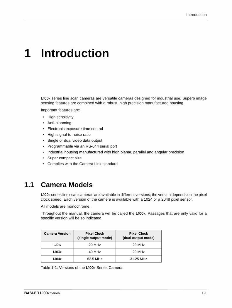
Spectral Response 300 - 1000 nm, peak at 700 nm (See Figure 1-1)
Anti-blooming 1:100 or better
Fixed Pattern Noise ± 1 gray value
Photo Resp. Non-uniformity ± 5 % typical
Pixel Clock Speed
Single Output Modes:
Dual Output Modes:
20 MHz
20 MHz
40 MHz
20 MHz
62.5 MHz
31.25 MHz
Maximum Line Rate
1024 Pixel Cameras:
2048 Pixel Cameras:
18.7 kHz
9.5 kHz
35.7 kHz
18.7 kHz
58.5 kHz
29.2 kHz
Minimum Line Rate 1 kHz
Pixel Depth Programmable 8 bit or 10 bit
Video Output Type Camera Link LVDS (RS-644 LVDS when used with the op-tional Basler Interface Converter (k-BIC))
Video Output Formats Single 8 Bit, Single 10 Bit, Dual 8 Bit, or Dual 10 Bit
Synchronization Via external ExSync signal or free-run
Exposure Time Control Edge-controlled, level-controlled, or programmable
Gain and Offset Programmable via a serial link
Connectors One, 26 pin, female MDR connectorOne, 6 pin, Hirose micro-miniature push-pull receptacle
Power Requirements 12 VDC ± 10%max. 6.5 W
12 VDC ± 10%max. 8.5 W
12 VDC ± 10%max. 10 W
Lens Adapters 1024 Pixel Cameras: C-mount or F-mount
2048 Pixel Cameras: F-mount
Housing Size (L x W x H) without lens adapter: 37.6 mm x 62 mm x 62 mm
with C-Mount Adapter: 40.1 mm x 62 mm x 62 mm
with F-mount adapter: 69.1 mm x 62 mm x 62 mm
Weight without lens adapter: ~ 175 g
with C-mount adapter: ~ 220 g
with F-mount adapter: ~ 285 g
Conformity CE, FCC
Table 1-2: L100k Series Performance Specifications
Introduction
BASLER L100k Series 1-3
DRAFT
Figure 1-1: Responsivity for L100k Series Cameras
1.3 Environmental Requirements
1.3.1 Temperature and HumidityHousing temperature during operation: 0 °C ... + 50 °C (+ 32 °F ... + 122 °F)
Humidity during operation: 20 % ... 80 %, relative, non-condensing
Housing temperature during storage: - 20 °C ... + 80 °C (- 4 °F ... + 176 °F)
Humidity during storage: 5 % ... 95 %, relative, non-condensing
1.3.2 VentilationAllow sufficient air circulation around the camera to prevent internal heat build-up in your systemand to keep the camera housing temperature during operation below 50 °C. Provide additionalcooling such as fans or heat sinks if necessary.
Warning!
Without sufficient cooling, the camera can get hot enough during opera-tion to cause burning when touched.
0
2
4
6
8
10
12
14
300 350 400 450 500 550 600 650 700 750 800 850 900 950 1000
Wavelength (nm)
Res
pons
ivity
(V/µ
J/cm
2 )

Introduction
1-4 BASLER L100k Series
DRAFT1.4 Precautions
Power
Do not remove the camera’s serial number label
If the label is removed and the serial number can’t be read from the camera’s registers, thewarranty is void.
Read the manual
Read the manual carefully before using the camera.
Keep foreign matter outside of the camera
Do not open the casing. Touching internal components may damage them.
Be careful not to allow liquid, flammable, or metallic material inside the camera housing. Ifoperated with any foreign matter inside, the camera may fail or cause a fire.
Electromagnetic Fields
Do not operate the camera in the vicinity of strong electromagnetic fields. Avoid electrostaticcharging.
Transporting
Only transport the camera in its original packaging. Do not discard the packaging.
Cleaning
Avoid cleaning the surface of the CCD sensor if possible. If you must clean it, use a soft, lint freecloth dampened with a small quantity of pure alcohol. Do not use methylated alcohol.Because electrostatic discharge can damage the CCD sensor, you must use a cloth that will notgenerate static during cleaning (cotton is a good choice).
Caution!
Be sure that all power to your system is switched off before you make or breakconnections to the camera. Making or breaking connections when power is oncan result in damage to the camera.
Caution!
The camera has no overvoltage protection. An input voltage higher than14 VDC will damage the camera.
Caution!
Do not reverse the polarity of the input power to the camera. Reversing the polarity of the input power can severely damage the camera and leave it non-operational.

Introduction
BASLER L100k Series 1-5
DRAFTTo clean the surface of the camera housing, use a soft, dry cloth. To remove severe stains, use asoft cloth dampened with a small quantity of neutral detergent, then wipe dry.
Do not use volatile solvents such as benzine and thinners; they can damage the surface finish.

Introduction
1-6 BASLER L100k Series
DRAFT
Camera Interface
BASLER L100k Series 2-1
DRAFT
2 Camera Interface
2.1 Connections
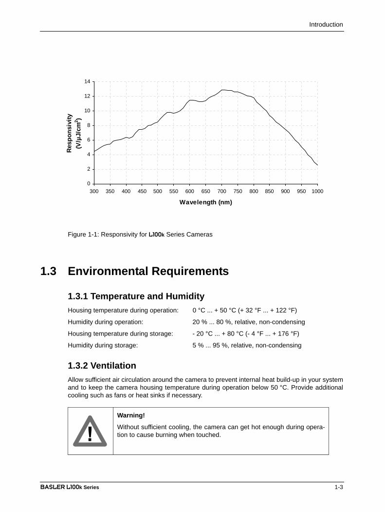
2.1.1 General DescriptionL100k series cameras are interfaced to external circuitry via two connectors located on the backof the camera:
• a 26 pin, .050” Mini D Ribbon (MDR) female connector used to transmit video data, controldata, and configuration data,
• a 6 pin, micro-miniature, push-pull receptacle used to provide power to the camera.A status LED located on the back of the camera is used to indicate power present and signalintegrity. Figure 2-1 shows the connectors and the LED.
Figure 2-1: L100k Connectors and LED
Micro-miniature6 Pin Receptacle
26 Pin FemaleMDR Connector
LED
Camera Interface
2-2 BASLER L100k Series
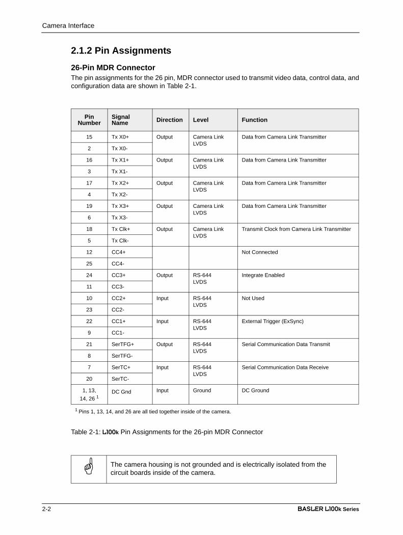
DRAFT2.1.2 Pin Assignments
26-Pin MDR ConnectorThe pin assignments for the 26 pin, MDR connector used to transmit video data, control data, andconfiguration data are shown in Table 2-1.
PinNumber
SignalName Direction Level Function
15 Tx X0+ Output Camera Link LVDS
Data from Camera Link Transmitter
2 Tx X0-
16 Tx X1+ Output Camera Link LVDS
Data from Camera Link Transmitter
3 Tx X1-
17 Tx X2+ Output Camera Link LVDS
Data from Camera Link Transmitter
4 Tx X2-
19 Tx X3+ Output Camera Link LVDS
Data from Camera Link Transmitter
6 Tx X3-
18 Tx Clk+ Output Camera Link LVDS
Transmit Clock from Camera Link Transmitter
5 Tx Clk-
12 CC4+ Not Connected
25 CC4-
24 CC3+ Output RS-644LVDS
Integrate Enabled
11 CC3-
10 CC2+ Input RS-644LVDS
Not Used
23 CC2-
22 CC1+ Input RS-644LVDS
External Trigger (ExSync)
9 CC1-
21 SerTFG+ Output RS-644LVDS
Serial Communication Data Transmit
8 SerTFG-
7 SerTC+ Input RS-644LVDS
Serial Communication Data Receive
20 SerTC-
1, 13, 14, 26 1
DC Gnd Input Ground DC Ground
1 Pins 1, 13, 14, and 26 are all tied together inside of the camera.
Table 2-1: L100k Pin Assignments for the 26-pin MDR Connector
The camera housing is not grounded and is electrically isolated from the circuit boards inside of the camera.
Camera Interface
BASLER L100k Series 2-3
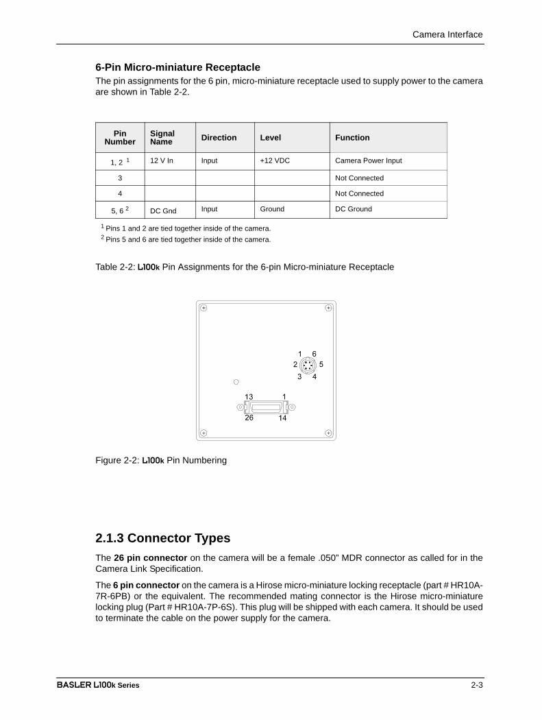
DRAFT6-Pin Micro-miniature ReceptacleThe pin assignments for the 6 pin, micro-miniature receptacle used to supply power to the cameraare shown in Table 2-2.
Figure 2-2: L100k Pin Numbering
2.1.3 Connector TypesThe 26 pin connector on the camera will be a female .050” MDR connector as called for in theCamera Link Specification.
The 6 pin connector on the camera is a Hirose micro-miniature locking receptacle (part # HR10A-7R-6PB) or the equivalent. The recommended mating connector is the Hirose micro-miniaturelocking plug (Part # HR10A-7P-6S). This plug will be shipped with each camera. It should be usedto terminate the cable on the power supply for the camera.
PinNumber
SignalName Direction Level Function
1, 2 1 12 V In Input +12 VDC Camera Power Input
3 Not Connected
4 Not Connected
5, 6 2 DC Gnd Input Ground DC Ground
1 Pins 1 and 2 are tied together inside of the camera.2 Pins 5 and 6 are tied together inside of the camera.
Table 2-2: L100k Pin Assignments for the 6-pin Micro-miniature Receptacle

Camera Interface
2-4 BASLER L100k Series
DRAFT2.2 Cable Information
2.2.1 Camera Link CableA Camera Link compatible MDR cable assembly is available from Basler as a stock item (part #1000013041 for a 3 meter cable and part # 1000013042 for a 5 meter cable). Alternatively, youcan use the cable assembly manufactured by 3M (part # 14X26-SZLB-XXX-0LC).
The maximum allowed length for the MDR cable used with an L100k is 10 meters.
2.2.2 Power CableFor proper EMI protection, the power supply cable attached to the Hirose plug must be a twin-cored, shielded cable. Also, the housing of the Hirose plug must be connected to the cable shieldand the cable must be connected to earth ground at the power supply.
Power requirements are given in Section 2.8.
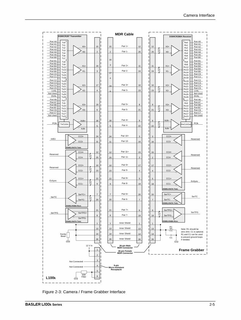
2.3 Camera Link Implementation in the L100k
The L100k uses a National Semiconductor DS90CR287 as a Camera Link transmitter. For aCamera Link receiver, we recommend that you use the National Semiconductor DS90CR288, theNational Semiconductor DS90CR288A or an equivalent. Detailed data sheets for thesecomponents are available at the National Semiconductor web site (www.national.com). The datasheets contain all of the information that you need to implement Camera Link, includingapplication notes.
The L100k uses a National Semiconductor DS90LV048A differential line receiver to receive theRS-644 camera control input signals and the serial communication input signal defined in theCamera Link specification. A DS90LV047A differential line transmitter is used to transmit the serialcommunication output signal defined in the specification. Detailed spec sheets for these devicesare available at the National Semiconductor web site (www.national.com).
The schematic in Figure 2-3 shows the interface for L100k and a typical implementation for theframe grabber interface.
Note that in order to access the Integrate Enabled signal, you must use the Baslerstock cable (see Sect. 2.5.6).
Note that the timing used for sampling the data at the Camera Link receiver in theframe grabber varies from device to device. On some receivers, TTL data must besampled on the rising edge of the receive clock, and on others, it must be sampledon the falling edge. Also, some devices are available which allow you to select eitherrising edge or falling edge sampling. Please consult the data sheet for the receiverthat you are using for specific timing information.
Camera Interface
BASLER L100k Series 2-5
DRAFT
Figure 2-3: Camera / Frame Grabber Interface
Port A0Port A1Port A2Port A3Port A4Port A5Port B0
Port B1Port B2Port B3Port B4Port B5Port C0Port C1
Port C2Port C3Port C4Port C5
LVALNot Used
DVAL
Port A6Port A7Port B6Port B7Port C6Port C7
Not Used
PClk
X0+
X0-
X1+
X1-
X2+
X2-
X3+
X3-
DS90CR287 Transmitter
L100k
15
2
16
3
17
4
19
6
Tx0Tx1Tx2Tx3Tx4Tx6Tx7
Tx8Tx9Tx12Tx13Tx14Tx15Tx18
Tx19Tx20Tx21Tx22Tx24Tx25Tx26
Tx27Tx5Tx10Tx11Tx16Tx17Tx23
TxCLKIn
Xclk+
Xclk-
18
5
24
11
12
25
10
23
22
9
Reserved
Reserved
ExSync
SerTC+
SerTC-
SerTFG+
SerTFG-
7
20
21
8
SerTC
SerTFG
1
13
14
26Gnd
15
2
16
3
17
4
19
6
18
5
24
11
12
25
10
23
22
9
7
20
21
8
1
13
14
26
MDR Cable
Port A0Port A1Port A2Port A3Port A4Port A5Port B0
Port B1Port B2Port B3Port B4Port B5Port C0Port C1
Port C2Port C3Port C4Port C5LVALNot UsedDVAL
Port A6Port A7Port B6Port B7Port C6Port C7Not Used
PClk
X0+
X0-
X1+
X1-
X2+
X2-
X3+
X3-
DS90CR288A Receiver
Frame Grabber
12
25
11
24
10
23
8
21
Rx0Rx1Rx2Rx3Rx4Rx6Rx7
Rx8Rx9
Rx12Rx13Rx14Rx15Rx18
Rx19Rx20Rx21Rx22Rx24Rx25Rx26
Rx27Rx5
Rx10Rx11Rx16Rx17Rx23
Xclk+
Xclk-
9
22
CC3+
CC3-
CC4+
CC4-
CC2+
CC2-
CC1+
CC1-
3
16
15
2
17
4
5
18
Reserved
Reserved
Reserved
ExSync
SerTC+
SerTC-
SerTFG+
SerTFG-
20
7
6
19
SerTC
SerTFG
1
13
14
26Gnd
12
25
11
24
10
23
8
21
9
22
3
16
15
2
17
4
5
18
20
7
6
19
1
13
14
26
Pair 1+
Pair 1-
Pair 2+
Pair 2-
Pair 3+
Pair 3-
Pair 5+
Pair 5-
Pair 4+
Pair 4-
Pair 10+
Pair 10-
Pair 11+
Pair 11-
Pair 9+
Pair 9-
Pair 8+
Pair 8-
Pair 6+
Pair 6-
Pair 7+
Pair 7-
Inner Shield
Inner Shield
Inner Shield
Inner Shield
R1
C1
Note: R1 should bezero ohm. C1 is optional.R1 and C1 can be usedto prevent ground loopsif needed.
RxCLKOut
DS90LV048A Rcvr.
DS90LV047A Tmtr.
DS90LV047A Tmtr.
DS90LV047A Tmtr.
DS90LV048A Rcvr.
1
2
3
4
5
6
Not Connected
Not Connected
12 V In
Gnd
EMIFilter
FerriteBead
IntEn
DS90LV047A Tmtr.
CC3+
CC3-
CC4+
CC4-
CC2+
CC2-
CC1+
CC1-
26-pin FemaleMDR Connector
26-pin MaleMDR Connector
6-pinMicro-miniature
Receptacle
Camera Interface
2-6 BASLER L100k Series
DRAFT2.4 Input Signal
The only control signal that can be input into the L100k is an external sync (ExSync) signal. ExSyncis an RS-644 LVDS signal as specified in the Camera Link standard. Section 2.4.1 describes thefunction of the ExSync signal.
2.4.1 ExSync: Controls Line Readout and Exposure TimeThe ExSync input signal is used to control exposure time and line read out. When the camera isoperating with an ExSync signal, three exposure time control modes are available: edge-controlled, level-controlled and programmable. For more detailed information on the three modes,see Section 3.2.
ExSync can be a periodic or non-periodic function. The frequency of the ExSync signaldetermines the camera’s line rate:
Note that ExSync is edge sensitive and therefore must toggle.
Minimum high time for the ExSync signal is 0.2 µs.
Maximum line rate 1Minimum ExSync signal period----------------------------------------------------------------------------------=

Camera Interface
BASLER L100k Series 2-7
DRAFT2.5 Output Signals
The camera’s output signals include a pixel clock, video data, and video data qualifiers such asline valid and data valid. Sections 2.5.1 through 2.5.4 describe the output signals.
2.5.1 Pixel ClockAs shown in Figure 2-3 and in Table 2-3, the pixel clock is assigned to the TxClkIn (transmit clock)pin of the Camera Link transmitter. The pixel clock is used to time the sampling and transmissionof pixel data as shown in Figures 2-4 through 2-10. The Camera Link transmitter used in L100kcameras requires pixel data to be sampled and transmitted on the falling edge of the clock.
The frequency of the pixel clock varies depending on the camera model and on the output modeof the camera. The available output modes are explained in detail in Sections through .
2.5.2 Line Valid BitAs shown in Figures 2-4 through 2-10, the line valid bit indicates that a valid line is beingtransmitted. Pixel data is only valid when this bit is high.
2.5.3 Data Valid BitThe data valid bit is only used with the L101k when the L101k is operating in Dual 10 Bit or Dual 8Bit output mode.
In dual output mode, valid pixel data is only transmitted on every other cycle of the pixel clock. Onthe L101k, the data valid bit is used to identify the cycles where valid pixel data is transmitted (seeSection 2.5.5). Pixel data is only valid when the line valid bit and the data valid bit are both high.
Note that the timing used for sampling the data at the Camera Link receiver in theframe grabber varies from device to device. On some receivers, data must be sam-pled on the rising edge of the pixel clock (receive clock), and on others, it must besampled on the falling edge. Also, some devices are available which allow you toselect either rising edge or falling edge sampling. Please consult the data sheet forthe receiver that you are using for specific timing information.

Camera Interface
2-8 BASLER L100k Series
DRAFT2.5.4 Video DataTable 2-3 lists the assignment of pixel data bits to the input ports on the transmitter in the cameraand the corresponding output pins on the receiver in the frame grabber. These bit assignmentscomply with the Camera Link standard. As shown in the table, the bit assignments for pixel datavary depending on the output mode setting of the camera. The available output modes areexplained in more detail in Section 2.5.5.
Table 2-3 also shows the assignment for the line valid bit, the data valid bit and the pixel clock.These assignments are constant for all output modes.
Port Camera FrameGrabber
Single 10 BitOutput Mode
Single 8 BitOutput Mode
Dual 10 BitOutput Mode
Dual 8 BitOutput Mode
Port A0 TxIN0 RxOUT0 Pixel Bit 0 Pixel Bit 0 Odd Pixel Bit 0 Odd Pixel Bit 0Port A1 TxIN1 RxOUT1 Pixel Bit 1 Pixel Bit 1 Odd Pixel Bit 1 Odd Pixel Bit 1Port A2 TxIN2 RxOUT2 Pixel Bit 2 Pixel Bit 2 Odd Pixel Bit 2 Odd Pixel Bit 2Port A3 TxIN3 RxOUT3 Pixel Bit 3 Pixel Bit 3 Odd Pixel Bit 3 Odd Pixel Bit 3Port A4 TxIN4 RxOUT4 Pixel Bit 4 Pixel Bit 4 Odd Pixel Bit 4 Odd Pixel Bit 4Port A5 TxIN6 RxOUT6 Pixel Bit 5 Pixel Bit 5 Odd Pixel Bit 5 Odd Pixel Bit 5Port A6 TxIN27 RxOUT27 Pixel Bit 6 Pixel Bit 6 Odd Pixel Bit 6 Odd Pixel Bit 6Port A7 TxIN5 RxOUT5 Pixel Bit 7 Pixel Bit 7
(MSB)Odd Pixel Bit 7 Odd Pixel Bit 7
(MSB)Port B0 TxIN7 RxOUT7 Pixel Bit 8 Not Used Odd Pixel Bit 8 Even Pixel Bit 0Port B1 TxIN8 RxOUT8 Pixel Bit 9
(MSB)Not Used Odd Pixel Bit 9
(MSB)Even Pixel Bit 1
Port B2 TxIN9 RxOUT9 Not Used Not Used Not Used Even Pixel Bit 2Port B3 TxIN12 RxOUT12 Not Used Not Used Not Used Even Pixel Bit 3Port B4 TxIN13 RxOUT13 Not Used Not Used Even Pixel Bit 8 Even Pixel Bit 4Port B5 TxIN14 RxOUT14 Not Used Not Used Even Pixel Bit 9
(MSB)Even Pixel Bit 5
Port B6 TxIN10 RxOUT10 Not Used Not Used Not Used Even Pixel Bit 6Port B7 TxIN11 RxOUT11 Not Used Not Used Not Used Even Pixel Bit 7
(MSB)Port C0 TxIN15 RxOUT15 Not Used Not Used Even Pixel Bit 0 Not UsedPort C1 TxIN18 RxOUT18 Not Used Not Used Even Pixel Bit 1 Not UsedPort C2 TxIN19 RxOUT19 Not Used Not Used Even Pixel Bit 2 Not UsedPort C3 TxIN20 RxOUT20 Not Used Not Used Even Pixel Bit 3 Not UsedPort C4 TxIN21 RxOUT21 Not Used Not Used Even Pixel Bit 4 Not UsedPort C5 TxIN22 RxOUT22 Not Used Not Used Even Pixel Bit 5 Not UsedPort C6 TxIN16 RxOUT16 Not Used Not Used Even Pixel Bit 6 Not UsedPort C7 TxIN17 RxOUT17 Not Used Not Used Even Pixel Bit 7 Not UsedDVAL TxIN26 RxOUT26 Data Valid Data Valid Data Valid Data ValidLVAL TxIN24 RxOUT24 Line Valid Line Valid Line Valid Line Valid
Not Used TxIN23 RxOUT23 Not Used Not Used Not Used Not UsedNot Used TxIN25 RxOUT25 Not Used Not Used Not Used Not Used
PClk TxCLKIn RxCLKOut Pixel Clock Pixel Clock Pixel Clock Pixel Clock
Table 2-3: Bit Assignments
Camera Interface
BASLER L100k Series 2-9
DRAFT2.5.5 Video Data Output ModesL100k series cameras can operate in Single 10 Bit, Single 8 Bit, Dual 10 Bit, or Dual 8 Bit outputmode. These modes are described in detail in this section .
Operation in Single 10 Bit or Single 8 Bit Output Mode (L101k, L103k and L104k)In Single 10 Bit mode, the pixel clock operates at 20 / 40 / 62.5 MHz for the L101k / L103k / L104krespectively. On each clock cycle, the camera transmits 10 bits of pixel data, a line valid bit and adata valid bit. The assignment of the bits is shown in Table 2-3.
The pixel clock is used to time data sampling and transmission. As shown in Figures 2-4 and 2-6,the camera samples and transmits data on each falling edge of the pixel clock.
The line valid bit indicates that a valid line is being transmitted. Pixel data is only valid when theline valid bit is high. The data valid bit is not used in this mode and should be ignored.
Operation in Single 8 Bit mode is similar to Single 10 Bit mode except that the two least significantbits output from each ADC are dropped and only 8 bits of data per pixel is transmitted.
Video Data Sequence1
When the camera is not transmitting valid data, the line valid bit sent on each cycle of the pixelclock will be low. Once the camera has completed line acquisition, it will begin to send valid data:
• On the pixel clock cycle where line data transmission begins, the line valid bit will becomehigh. Ten of the bits transmitted during this clock cycle will contain the data for pixel numberone.
• On the second cycle of the pixel clock, the line valid bit will be high. Ten of the bits transmit-ted during this clock cycle will contain the data for pixel number two.
• On the third cycle of the pixel clock, the line valid bit will be high. Ten of the bits transmittedduring this clock cycle will contain the data for pixel number three.
• This pattern will continue until all of the pixel data for the line has been transmitted. (A total of1024 cycles for cameras with a 1K sensor and 2048 cycles for cameras with a 2K sensor.)
• After all of the pixels have been transmitted, the line valid bit will become low indicating thatvalid line data is no longer being transmitted.
Figures 2-4 and 2-5 show the data sequence when the camera is operating in edge-controlled orlevel-controlled exposure mode. Figure 2-6 shows the data sequence when the camera isoperating in programmable exposure mode.
____________________1 The data sequence assumes that the camera is operating in 10 bit mode. If the camera is
operating in 8 bit mode, only 8 bits of data per pixel will be transmitted.
The data sequence outlined below, along with Figures 2-4 and 2-6, describe what ishappening at the inputs to the Camera Link transmitter in the camera.
Note that the timing used for sampling the data at the Camera Link receiver in theframe grabber varies from device to device. On some receivers, data must be sam-pled on the rising edge of the pixel clock (receive clock), and on others, it must besampled on the falling edge. Also, some devices are available which allow you toselect either rising edge or falling edge sampling. Please consult the data sheet forthe receiver that you are using for specific timing information.
Camera Interface
2-10 BASLER L100k Series
DRAFT
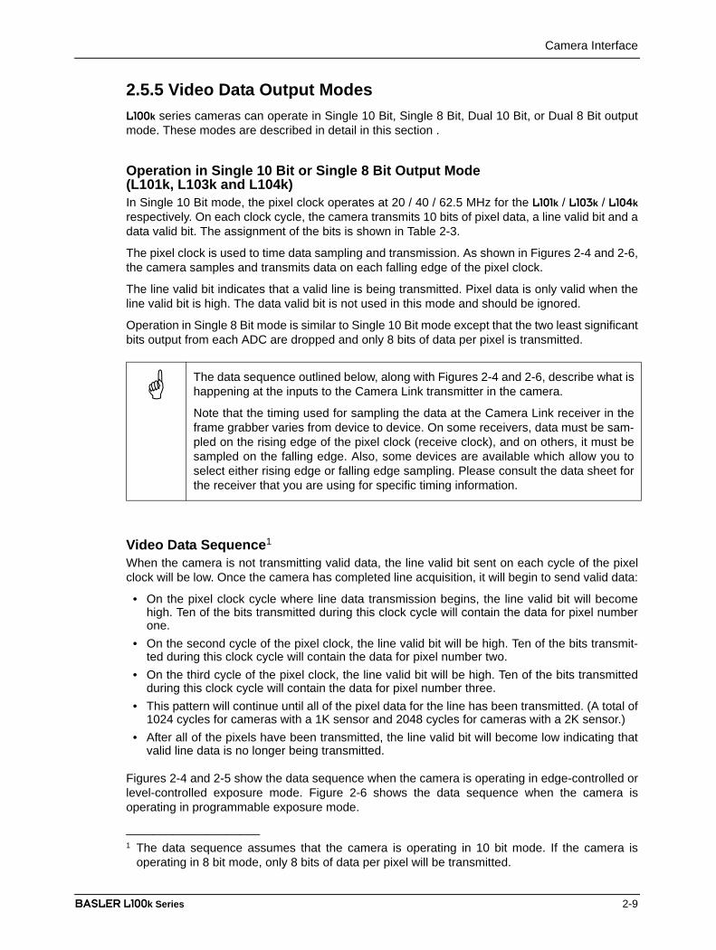
Figure 2-4: L101k Single 10 Bit or Single 8 Bit Output Mode with Edgeor Level Controlled Exposure
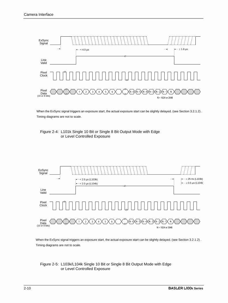
Figure 2-5: L103k/L104k Single 10 Bit or Single 8 Bit Output Mode with Edgeor Level Controlled Exposure
PixelData
(10 or 8 bits)
4 5 61 2 3
PixelClock
LineValid
ExSyncSignal
< 4.0 µs ≤ 1.8 µs
N - 1N - 2N - 3N - 4N - 5N - 6 N
N = 1024 or 2048
When the ExSync signal triggers an exposure start, the actual exposure start can be slightly delayed. (see Section 3.2.1.2) .
Timing diagrams are not to scale.
PixelData
(10 or 8 bits)
4 5 61 2 3
PixelClock
LineValid
ExSyncSignal
< 2.5 µs (L103k) ≥ 25 ns (L103k)
N - 1N - 2N - 3N - 4N - 5N - 6 N
N = 1024 or 2048
≥ 0.5 µs (L104k)< 2.0 µs (L104k)
When the ExSync signal triggers an exposure start, the actual exposure start can be slightly delayed. (see Section 3.2.1.2) .
Timing diagrams are not to scale.

Camera Interface
BASLER L100k Series 2-11
DRAFT
Figure 2-6: Single 10 Bit or Single 8 Bit Output Mode with Programmable Exposure
PixelData
(10 or 8 bits)
4 5 61 2 3
PixelClock
LineValid
N - 1N - 2N - 3N - 4N - 5N - 6 N
N = 1024 or 2048
end ofprogrammed
time
< 2.5 µs (L103k)
< 4.0 µs (L101k)
< 2.0 µs (L104k)
When the ExSync signal triggers an exposure start, the actual exposure start can be slightly delayed. (see Section 3.2.1.2) .
Timing diagrams are not to scale.

Camera Interface
2-12 BASLER L100k Series
DRAFTOperation in Dual 10 Bit or Dual 8 Bit Output Mode (L101k only)In Dual 10 Bit mode, the pixel clock operates at 20 MHz for the L101k. On every pixel clock cycle,the camera transmits a line valid bit and a data valid bit. On every other cycle of the pixel clock,the camera transmits 10 bits of data for two pixels. The assignment of the bits is shown in Table2-3.
The pixel clock is used to time data sampling and transmission. As shown in Figures 2-7 and 2-8,the camera samples and transmits data on each falling edge of the pixel clock.
The line valid bit indicates that a valid line is being transmitted. The data valid bit indicates thatvalid pixel data is being transmitted. Pixel data is only valid when the line valid and data valid bitsare both high.
Operation in Dual 8 Bit mode is similar to Dual 10 Bit mode except that the two least significantbits output from each ADC are dropped and only 8 bits of data per pixel is transmitted.
Video Data Sequence1
When the camera is not transmitting valid data, the line valid bit and the data valid bit sent on eachcycle of the pixel clock will be low. Once the camera has completed line acquisition, it will beginto send valid data:
• On the pixel clock cycle where line data transmission begins, the line valid bit and the datavalid bit will become high. Ten of the bits transmitted during this clock cycle will contain thedata for pixel number one and ten of the bits will contain data for pixel number two.
• On the second cycle of the pixel clock, the data valid bit will be low. Valid data is not transmit-ted during this cycle.
• On the third cycle of the pixel clock, the line valid bit and the data valid bit will be high. Ten ofthe bits transmitted during this clock cycle will contain the data for pixel number three and tenof the bits will contain data for pixel number four.
• On the fourth cycle of the pixel clock, the data valid bit will be low. Valid data is not transmit-ted during this cycle.
• This pattern will continue until all of the pixel data for the line has been transmitted. (A total of1024 cycles for cameras with a 1K sensor and 2048 cycles for cameras with a 2K sensor.)
• After all of the pixels have been transmitted, the line valid bit will become low indicating thatvalid line data is no longer being transmitted.
Figure 2-7 shows the data sequence when the camera is operating in edge-controlled or level-controlled exposure mode and Figure 2-8 shows the data sequence when the camera is operatingin programmable exposure mode.
____________________1 The data sequence assumes that the camera is operating in 10 bit mode. If the camera is
operating in 8 bit mode, only 8 bits of data per pixel will be transmitted.
The data sequence outlined below, along with Figures 2-7 and 2-8, describe what ishappening at the inputs to the Camera Link transmitter in the camera.
Note that the timing used for sampling the data at the Camera Link receiver in theframe grabber varies from device to device. On some receivers, data must be sam-pled on the rising edge of the pixel clock (receive clock), and on others, it must besampled on the falling edge. Also, some devices are available which allow you toselect either rising edge or falling edge sampling. Please consult the data sheet forthe receiver that you are using for specific timing information.

Camera Interface
BASLER L100k Series 2-13
DRAFT
Figure 2-7: L101k Dual 10 or 8 Bit Output Mode with Edge or Level-controlled Exposure
Figure 2-8: L101k Dual 10 or 8 Bit Output Mode with Programmable Exposure
OddPixelData
(10 or 8 bits)
5 71 3
LineValid
N - 1N - 3N - 5N - 7
PixelClock
EvenPixelData
(10 or 8 bits)
6 82 4 N - 2N - 4N - 6 N
N = 1024 or 2048
DataValid
ExSyncSignal
< 4.0 µs ≤ 1.8 µs
When the ExSync signal triggers an exposure start, the actual exposure start can be slightly delayed. (see Section 3.2.1.2) .
Timing diagrams are not to scale.
OddPixelData
(10 or 8 bits)
5 71 3
DataValid
LineValid
< 4.0 µs
N - 1N - 3N - 5N - 7
PixelClock
EvenPixelData
(10 or 8 bits)
6 82 4 N - 2N - 4N - 6 N
N = 1024 or 2048
end ofprogrammed
time
When the ExSync signal triggers an exposure start, the actual exposure start can be slightly delayed. (see Section 3.2.1.2) .
Timing diagrams are not to scale.
Camera Interface
2-14 BASLER L100k Series
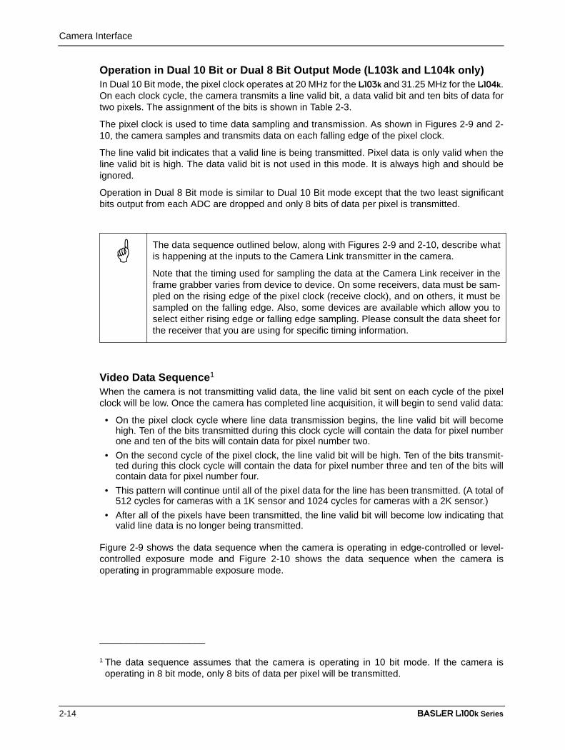
DRAFTOperation in Dual 10 Bit or Dual 8 Bit Output Mode (L103k and L104k only)In Dual 10 Bit mode, the pixel clock operates at 20 MHz for the L103k and 31.25 MHz for the L104k.On each clock cycle, the camera transmits a line valid bit, a data valid bit and ten bits of data fortwo pixels. The assignment of the bits is shown in Table 2-3.
The pixel clock is used to time data sampling and transmission. As shown in Figures 2-9 and 2-10, the camera samples and transmits data on each falling edge of the pixel clock.
The line valid bit indicates that a valid line is being transmitted. Pixel data is only valid when theline valid bit is high. The data valid bit is not used in this mode. It is always high and should beignored.
Operation in Dual 8 Bit mode is similar to Dual 10 Bit mode except that the two least significantbits output from each ADC are dropped and only 8 bits of data per pixel is transmitted.
Video Data Sequence1
When the camera is not transmitting valid data, the line valid bit sent on each cycle of the pixelclock will be low. Once the camera has completed line acquisition, it will begin to send valid data:
• On the pixel clock cycle where line data transmission begins, the line valid bit will becomehigh. Ten of the bits transmitted during this clock cycle will contain the data for pixel numberone and ten of the bits will contain data for pixel number two.
• On the second cycle of the pixel clock, the line valid bit will be high. Ten of the bits transmit-ted during this clock cycle will contain the data for pixel number three and ten of the bits willcontain data for pixel number four.
• This pattern will continue until all of the pixel data for the line has been transmitted. (A total of512 cycles for cameras with a 1K sensor and 1024 cycles for cameras with a 2K sensor.)
• After all of the pixels have been transmitted, the line valid bit will become low indicating thatvalid line data is no longer being transmitted.
Figure 2-9 shows the data sequence when the camera is operating in edge-controlled or level-controlled exposure mode and Figure 2-10 shows the data sequence when the camera isoperating in programmable exposure mode.
____________________
1 The data sequence assumes that the camera is operating in 10 bit mode. If the camera isoperating in 8 bit mode, only 8 bits of data per pixel will be transmitted.
The data sequence outlined below, along with Figures 2-9 and 2-10, describe whatis happening at the inputs to the Camera Link transmitter in the camera.
Note that the timing used for sampling the data at the Camera Link receiver in theframe grabber varies from device to device. On some receivers, data must be sam-pled on the rising edge of the pixel clock (receive clock), and on others, it must besampled on the falling edge. Also, some devices are available which allow you toselect either rising edge or falling edge sampling. Please consult the data sheet forthe receiver that you are using for specific timing information.
Camera Interface
BASLER L100k Series 2-15
DRAFT
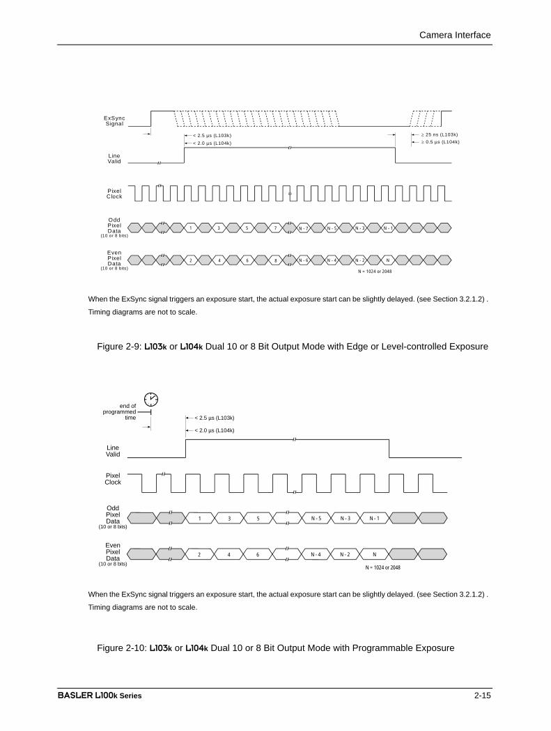
Figure 2-9: L103k or L104k Dual 10 or 8 Bit Output Mode with Edge or Level-controlled Exposure
Figure 2-10: L103k or L104k Dual 10 or 8 Bit Output Mode with Programmable Exposure
OddPixelData
(10 or 8 bits)
5 71 3
LineValid
N - 1N - 3N - 5N - 7
PixelClock
EvenPixelData
(10 or 8 bits)
6 82 4 N - 2N - 4N - 6 N
N = 1024 or 2048
ExSyncSignal
< 2.5 µs (L103k) ≥ 25 ns (L103k)≥ 0.5 µs (L104k)< 2.0 µs (L104k)
When the ExSync signal triggers an exposure start, the actual exposure start can be slightly delayed. (see Section 3.2.1.2) .
Timing diagrams are not to scale.
OddPixelData
(10 or 8 bits)51 3
PixelClock
LineValid
N - 1N - 3N - 5
N = 1024 or 2048
EvenPixelData
(10 or 8 bits)
62 4 NN - 2N - 4
end ofprogrammed
time
< 2.0 µs (L104k)
< 2.5 µs (L103k)
When the ExSync signal triggers an exposure start, the actual exposure start can be slightly delayed. (see Section 3.2.1.2) .
Timing diagrams are not to scale.

Camera Interface
2-16 BASLER L100k Series
DRAFT2.5.6 Integrate Enabled SignalAn RS-644 LVDS output signal called Integrate Enabled (IntEn) is available on L100k cameras.The integrate enabled signal indicates that an exposure is taking place. The signal will go highwhen each exposure begins and go low when the exposure ends. As shown in the schematic inSection 2.3, the IntEn signal is available on pins 24 and 11 of the L100k.
The integrate enabled signal can not be easily accessed if a standard Camera Link Cable is usedbetween the camera and the frame grabber. However, a Camera Link cable which allows easyaccess to this signal is available from Basler as a stock item (part # 100013041 for a 3 meter cableand part # 100013042 for a 5 meter cable).
In the Basler cable, the wires which carry the integrate enabled signal from the camera are notattached to the pins in the frame grabber end of the cable. Instead, the wires are unterminatedand are folded back inside of the connector housing on the frame grabber end (see Figure 2-11below). If you open the connector housing, you can locate the wires and use them to access theintegrate enabled signal. As shown below, a blue wire carries the positive signal and a gray wirecarries the negative signal. The wires require a 100 Ohm termination.
In edge-controlled mode, the IntEn signal is low during charge transfer.
Figure 2-11: Basler Camera Link Cable
If you use a standard Camera Link cable to connect the L100k to a Camera Linkframe grabber, the RS-644 LVDS transmitter for the integrate enabled signal will beconnected to an RS-644 LVDS transmitter in the frame grabber as shown in theschematic in Section 2.3. Because the transmitter in the camera is a low currentsource and because the opposing transmitter in the frame grabber is typically shortcircuit protected, this configuration will not cause damage to the camera or the framegrabber.

Camera Interface
BASLER L100k Series 2-17
DRAFT2.6 RS-644 Serial Communication
The L100k is equipped for RS-644 serial communication via the frame grabber as specified in theCamera Link standard. The RS-644 serial connection in the Camera Link interface is used to issuecommands to the camera for changing modes and parameters. The serial link can also be usedto query the camera about its current setup.
The Basler Camera Configuration Tool Plus (CCT+) is a convenient, graphical interface that canbe used to change camera modes and parameters via the serial connection. The configurationtool is installed as part of the camera installation procedure shown in the CCT+ booklet that isshipped with the camera. Section 4.1 provides some basic information about the configurationtool. Detailed instructions for using the tool are included in the on-line help file that is installed withthe tool.
Basler has also developed a binary command protocol that can be used to change camera modesand parameters directly from your own application via the serial connection using either the APIdelivered with the frame grabber or the Basler CPA driver. See Section 4.2 for details on the binarycommand format.
2.6.1 Making the Serial ConnectionFrame grabbers compliant with the Camera Link specification are equipped with a serial portintegrated into the Camera Link interface that can be used for RS-644 serial communication. Thecharacteristics of the serial port can vary from manufacturer to manufacturer.
If you are using the Basler Camera Configuration Tool Plus to configure the camera, the tool willdetect the characteristics of the serial port on the frame grabber and will determine the appropriatesettings so that the tool can open and use the port.
If you are configuring the camera using binary commands from within your application software,your software must be able to access the frame grabber serial port and to determine theappropriate settings so that it can open and use the port. Please consult your frame grabber’sdocumentation to determine the port access method and the port characteristics.
In order for the Camera Configuration Tool Plus to detect and use the port, the char-acteristics of the port must comply with the Camera Link standard and the DLL calledfor in the standard must be present.

Camera Interface
2-18 BASLER L100k Series
DRAFT2.7 Converting Camera Link Output to RS-644
with a k-BICOn the l100k, video data is output from the camera in Camera Link LVDS format and parameterchange commands are issued to the camera using RS-644 serial communication via the framegrabber. On older cameras, video data was output using an RS-644 LVDS format and commandswere issued using RS-232 serial communication via the host PC. The output from l100k camerascan be converted to the older style of output by using a Basler Interface Converter for k-seriescameras (k-BIC). The k-BIC is a small device which attaches to the l100k with a Camera Linkcompatible cable. For complete information on the k-BIC, refer to the k-BIC Users Manual and thek-BIC installation guide.
2.8 DC PowerThe L100k requires 12 VDC (± 10%) power. The maximum power consumption is approximately6.5 W / 8.5 W / 10 W for the L101k / L103k / L104k respectively.
Also, note the information about the 6-pin connector in Section 2.1.3 and on the power cable inSection 2.2.2.
2.9 Status LEDThe L100k has a status LED on the back of the camera. The LED is used to indicate that power ispresent and to indicate an error condition if one is detected. See Section 6.1 for details.
Caution!
The camera has no overvoltage protection. An input voltage higher than14 VDC will damage the camera
Caution!
Do not reverse the polarity of the input power to the camera. Reversing the polarity of the input power can severely damage the camera and leave it non-operational.
Operation and Features
BASLER L100k Series 3-1
DRAFT
3 Basic Operation and Features
3.1 Functional DescriptionBASLER L100k line scan cameras employ a CCD-sensor chip which provides features such aselectronic exposure time control and anti-blooming. Exposure time is normally controlled via anexternal trigger (ExSync) signal. The ExSync signal facilitates periodic or non-periodic pixelreadout.
When exposure is controlled by an ExSync signal, exposure time can be either edge-controlled,level-controlled, or programmable. In edge-controlled mode, charge is accumulated over theentire period of the ExSync signal and a rising edge of ExSync triggers the readout of accumulatedcharges from the sensor elements to the CCD shift registers. In level-controlled mode, charge isaccumulated when the ExSync signal is low and a rising edge of ExSync triggers the readout. Inprogrammable mode, exposure time can be programmed to a predetermined time period. In thiscase, exposure begins on the rising edge of ExSync and accumulated charges are read out whenthe programmed exposure time ends.
A free-run mode that allows the camera to operate without an ExSync signal is also available. Infree-run mode, the camera generates its own internal control signal and the internal signal is usedto control exposure and charge read out. When operating in free-run, the camera outputs linescontinuously.
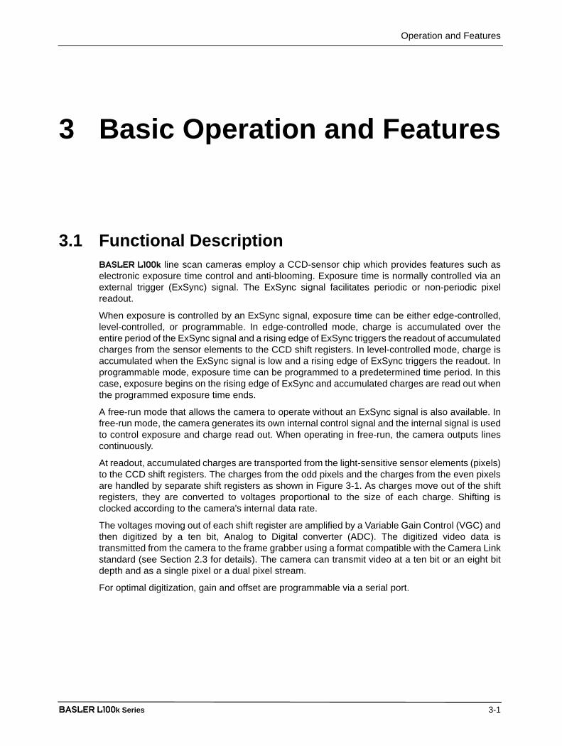
At readout, accumulated charges are transported from the light-sensitive sensor elements (pixels)to the CCD shift registers. The charges from the odd pixels and the charges from the even pixelsare handled by separate shift registers as shown in Figure 3-1. As charges move out of the shiftregisters, they are converted to voltages proportional to the size of each charge. Shifting isclocked according to the camera's internal data rate.
The voltages moving out of each shift register are amplified by a Variable Gain Control (VGC) andthen digitized by a ten bit, Analog to Digital converter (ADC). The digitized video data istransmitted from the camera to the frame grabber using a format compatible with the Camera Linkstandard (see Section 2.3 for details). The camera can transmit video at a ten bit or an eight bitdepth and as a single pixel or a dual pixel stream.
For optimal digitization, gain and offset are programmable via a serial port.

Operation and Features
3-2 BASLER L100k Series
DRAFT
Figure 3-1: L100k Sensor Architecture
ADC
VGCADC
CCD Sensor
Odd Shift Register
Even Shift Register(amplifier)
VGC(amplifier)
Pixels
Operation and Features
BASLER L100k Series 3-3
DRAFT3.2 Exposure Time Control Modes
L100k series cameras can operate under the control of an external trigger signal (ExSync) or canoperate in “free-run.” In free-run, the camera generates its own internal control signal and doesnot require an ExSync signal.
3.2.1 ExSync Controlled Operation
3.2.1.1 Basics of ExSync Controlled OperationIn ExSync operation, the camera’s line rate and exposure time are controlled by an externallygenerated (ExSync) signal. The ExSync signal is typically supplied to the camera by a framegrabber board. You should refer to the manual supplied with your frame grabber board todetermine how to set up the ExSync signal that is being supplied to the camera.
When the camera is operating under the control of an ExSync signal, the length of the ExSyncsignal period determines the camera’s line rate. (Line Rate = 1/ExSync Signal Period.) ExSynccan be periodic or non-periodic.
When the camera is operating with an ExSync signal, it has three modes of exposure time controlavailable: edge-controlled mode, level-controlled mode, and programmable mode.
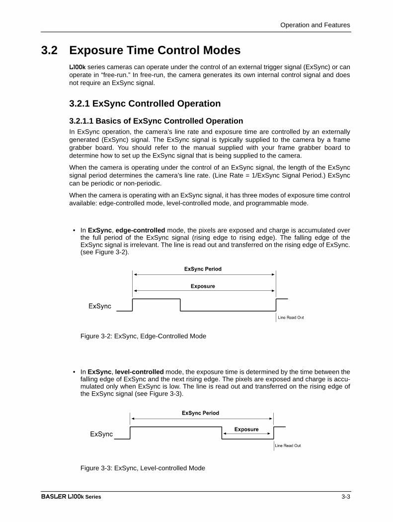
• In ExSync, edge-controlled mode, the pixels are exposed and charge is accumulated overthe full period of the ExSync signal (rising edge to rising edge). The falling edge of theExSync signal is irrelevant. The line is read out and transferred on the rising edge of ExSync.(see Figure 3-2).
Figure 3-2: ExSync, Edge-Controlled Mode
• In ExSync, level-controlled mode, the exposure time is determined by the time between thefalling edge of ExSync and the next rising edge. The pixels are exposed and charge is accu-mulated only when ExSync is low. The line is read out and transferred on the rising edge ofthe ExSync signal (see Figure 3-3).
Figure 3-3: ExSync, Level-controlled Mode

Operation and Features
3-4 BASLER L100k Series
DRAFT• In ExSync, programmable mode, the rising edge of ExSync triggers exposure and charge
accumulation for a pre-programmed period of time. The line is read out and transferred at theend of the pre-programmed period. The falling edge of ExSync is irrelevant (see Figure 3-4).A parameter called “Timer 1” is used to set the length of the pre-programmed exposure period.
Figure 3-4: ExSync, Programmable Mode
You can set the camera to operate in one of the ExSync controlled exposure modes using eitherthe Camera Configuration Tool Plus (see Section 4.1) or binary commands (see Section 4.2).
With the Camera Configuration Tool Plus, you use the Exposure Time Control Mode setting in theExposure parameter group to set the camera for ExSync operation and to select the edge-controlled, level controlled or programmable exposure time control mode. If you select theprogrammable mode, you must also enter an exposure time. When you enter an exposure time,the configuration tool will automatically set the “Timer 1” parameter to the correct value.
With binary commands, you must use the Exposure Time Control Mode command to selectExSync edge-controlled, ExSync level-controlled or ExSync programmable mode (see Section4.2.4.2). If you choose the programmable mode, you must also use the Timer 1 command to setthe exposure time.
ExSyncExposure
Line Read Out
ExSync Period
(Timer 1)

Operation and Features
BASLER L100k Series 3-5
DRAFT3.2.1.2 Recommendations When Using ExSyncWhen using an ExSync signal to control operation, several general guidelines must be followed:
• ExSync must toggle.• The ExSync signal period must not be lower than a defined minimum. The minimum ExSync
period for each camera version is shown in Table 3-1.
• The ExSync signal must remain high for at least 0.2 µs.• The minimum exposure time is 1 µs. That means that:
In ExSync level-controlled mode, the ExSync signal must remain low for at least 1 µs.
In ExSync programmabe mode, the programmed exposure time must be at least 1 µs.
• In the ExSync Programmable mode:Maximum allowed programmed exposure time = ExSync signal period - 1 µs.
• In ExSync edge-controlled and ExSync level-controlled modes, the relationship between thethe fall of the line valid signal and the rise of the ExSync signal must meet the minimumrequirements shown in Figures 2-4, 2-5, 2-7, and 2-9.
• When an exposure is triggered by the ExSync signal, the actual start of exposure can bedelayed by up to 1.3 µs. (This is commonly referred to as an exposure start delay.) The max-imum delay depends on the camera model and the exposure mode that you are using. Table3-2 shows the maximum delay for each camera model and exposure mode.The actual length of the exposure time will be equal to the exposure time triggered by theExSync signal minus the delay. Actual exposure can be monitored using the Integrate Enabledsignal (see Section 3.4).
L101k L103k L104k
1024 Pixel CCD 53.4 µs 28.0 µs 17.1 µs
2048 Pixel CCD 105.0 µs 53.3 µs 34.2 µs
Table 3-1: Minimum ExSync Signal Period
Exposure Mode L101k L103k L104k
Edge-controlled 1.3 µs 1.1 µs 0.55 µs
Level-controlled 0.15 µs 0.15 µs 0.15 µs
Programmable 0.45 µs 0.45 µs 0.45 µs
Table 3-2: Maximum Exposure Start Delays

Operation and Features
3-6 BASLER L100k Series
DRAFT3.2.2 Free Run
3.2.2.1 Basics of Free-run Controlled OperationIn free-run, no ExSync signal is required. The camera generates a continuous internal controlsignal based on two programmable parameters: “Timer 1” and “Timer 2”. Timer 1 determines howlong the internal signal will remain low and Timer 2 determines how long the signal will remainhigh.
When the camera is operating in free-run, the length of the control signal period determines thecamera’s line rate. The control signal period is equal to Timer 1 plus Timer 2:
When the camera is operating in free-run, it exposes and outputs lines continuously.
In free-run, two modes of operation are available: edge-controlled and programmable.
• In free-run, edge-controlled mode, the pixels are exposed and charge is accumulated overthe full period of the internal control signal (rising edge to rising edge). The falling edge of thecontrol signal is irrelevant. The line is read out and transferred on the rising edge of the inter-nal control signal (see Figure 3-5).In this mode, the exposure time is the sum of Timer 1 plus Timer 2:
Figure 3-5: Free-run, Edge-controlled Mode
Timer 1 Timer 2+ Control signal period 1Line rate-----------------------= =
Timer 1 Timer 2+ Exposure 1Line rate-----------------------= =
Timer 2 Timer 1
Exposure
line read out
Control Signal Period
InternalControlSignal

Operation and Features
BASLER L100k Series 3-7
DRAFT• In free-run, programmable mode, the pixels are exposed and charge is accumulated when
the internal control signal is low. The line is read out and transferred on the rising edge of theinternal control signal (see Figure 3-6).In this mode, the Timer 1 setting determines the length of exposure:
Figure 3-6: Free-run, Programmable Mode
You can set the camera to operate in free-run using either the Camera Configuration Tool Plus(see Section 4.1) or binary commands (see Section 4.2).
With the Camera Configuration Tool Plus, you use the Exposure Time Control Mode Setting in theExposure parameter group to set the camera for free-run and to select the edge-controlled orprogrammable exposure time control mode. If you choose to operate the camera in free-run, theconfiguration tool will require you to enter a line rate; if you are using the programmable mode,you must also enter an exposure time. The configuration tool will automatically set the Timer 1 andTimer 2 parameters based on the values that you enter in the Exposure parameter group.
With binary commands you must use the Exposure Time Control Mode command to select thefree-run, edge-controlled or free-run, programmable mode (see Section 4.2.4.2). You must alsouse the Timer 1 command to set Timer 1 and the Timer 2 command to set Timer 2.
Timer 1 Exposure=
Timer 2 Rest of the control signal period=
Timer 1Timer 2
Exposureline read out
Control Signal Period
InternalControlSignal

Operation and Features
3-8 BASLER L100k Series
DRAFT3.2.2.2 Recommendations When Using Free-runWhen using free-run mode to control operation, several general guidelines must be followed:
• In the free-run mode, the period of the internal control signal is equal to the sum of Timer 1plus Timer 2. This sum must not be lower than the minimum shown in Table 3-3.
• The minimum recommended exposure time is 1 µs.
L101k L103k L104k
1024 Pixel CCD 53.3 µs 28.0 µs 17.1 µs
2048 Pixel CCD 104.3 µs 53.3 µs 34.2 µs
Table 3-3: Minimum Control Signal Periods
Operation and Features
BASLER L100k Series 3-9
DRAFT3.3 Video Data Output Modes
L100k series cameras can output video data using four different modes: Single 10 Bit mode, Single8 Bit mode, Dual 10 Bit mode and Dual 8 Bit mode. These modes of operation are described indetail in Section 2.5.5.
You can select the video data output mode using either the Camera Configuration Tool Plus (seeSection 4.1) or binary commands (see Section 4.2).
With the Camera Configuration Tool Plus, you use the Video Data Output Mode setting in theOutput parameter group.
With binary commands, you use the Video Data Output Mode command (see Section 4.2.4.1).
3.4 Integrate Enabled SignalAn output signal called Integrate Enabled (IntEn) is available on L100k cameras. The integrateenabled signal indicates that an exposure is taking place. The signal will go high when eachexposure begins and go low when the exposure ends. The characteristics of the signal aredescribed in more detail in Section 2.5.6.
In cases where flash exposure is required, the integrate enabled signal is useful as a flash trigger.

Operation and Features
3-10 BASLER L100k Series
DRAFT3.5 Gain and Offset
The pixels in the CCD sensor output voltage signalswhen they are exposed to light. These voltages areamplified by VGCs and transferred to ADCs wherethey are converted to digital output signals (see Figure3-1).
Two parameters, gain and offset are associated witheach ADC. As shown in Figures 3-7 and 3-8,increasing or decreasing the gain increases ordecreases the amplitude of the signal that is input tothe ADC. Increasing or decreasing the offset movesthe signal up or down the measurement scale but doesnot change the signal amplitude.
For most applications, black should have a gray valueof 1 and white should have a gray value of 254 (in 8 bitoutput mode) or 1022 (in 10 bit output mode). Attemptto achieve this by varying exposure and illuminationrather than changing the camera’s gain. The defaultgain is the optimal operating point (low noise, goododd/even channel match) and should be used ifpossible.
Internally, the camera processes odd and even pixelsseparately in two different data channels (see Figure 3-1). Consequently, gain must be adjusted separately forthe odd pixels and for the even pixels. Due to variationsin the camera's electronics, a gain setting on the oddchannel may produce a different output than the samegain setting on the even channel. Gain balancebetween the odd and even channels is important tomaintain uniform output data with minimal gray valuedifferences between odd and even pixels. See Section3.5.1 for more detailed information on balancing thegain.
Since the black level is very stable, you do not need to adjust the offset when you change the gain.The offset is also set separately for the odd and the even channel, but the offset on the channelsdoes not need to be balanced. An odd and even offset of, for example, 0 both produce the sameoutput.
You can set the gain and offset using either the Camera Configuration Tool Plus (see Section 4.1)or binary commands (see Section 4.2).
With the Camera Configuration Tool Plus, you use the Gain setting and the Offset setting in theGain and Offset parameter group to set the gain and offset.
With binary commands, you must use the Odd Pixel Gain and Even Pixel Gain commands to setthe gain and the Odd Pixel Offset and Even Pixel Offset commands to set the offset (see Sections .
Because increasing gain increases both signal and noise, the signal to noise ratio doesnot change significantly when gain is increased.
inputsignalto ADC
[V]
light intensity [μJ/cm2]
increasing gainincreases theamplitude of
the input signal
Figure 3-7: Gain
increasing offsetmoves the input
signal up themeasurement scale
offset
inputsignalto ADC
[V]
light intensity [μJ/cm2]
Figure 3-8: Offset
Operation and Features
BASLER L100k Series 3-11
DRAFT3.5.1 Balancing the Gain on Odd and Even PixelsAs described on the previous page, gain alignment between the channels is important to maintainuniform output data with minimal gray value differences between odd and even pixels.
In some applications, multiple cameras are used, for example, when several line scan camerasare used next to each other to form one large image. Another example is that a camera in anexisting application is replaced. In these cases, it is also necessary to balance the gain betweencameras.
To meet the goals of balanced channels and comparable camera output, each Basler camera iscalibrated before it leaves the factory. This calibration procedure has the following effects:
• The factory gain settings for the odd and even channels are aligned so that they equallyamplify the signal and a uniform output is achieved on both channels. In addition, they areset to a low gain value to obtain an optimal operating point (low noise, good odd/even chan-nel match)
• There are reference gain values which can be used to calculate higher or lower odd andeven gain settings so that the channels remain balanced.
• All cameras have default gain settings and reference gain values which match the output of afactory master camera of the same type. This output is referred to as 0 dB. So if a camera’sgain is set to 2 dB, this means 2 dB more than the gain of the master camera.
The reference gain values can be used to calculate higher or lower gain settings that will keep theodd and even channels in balance and comparable to other cameras of the same type.
If you use the Gain setting in the Camera Configuration Tool Plus (see Section 4.1) to set the gainon your camera, an “auto-balance” feature will automatically use the stored reference values tokeep the channels in balance. If you want to set the camera so that the channels are not balanced,you can use the Gain Balance setting to change the gain on the even pixels only.
If you use binary commands (see Section 4.2) to set the gain, you can use the reference valuesto calculate gain settings that will keep the channels in balance. To do this, you must select adesired gain in dB to achieve and then use the reference values along with the formulas shownon pages 3-12 through 3-15 to calculate the required settings for the odd pixel gain and for theeven pixel gain. You can then enter the calculated settings into the camera using the appropriatecommands.
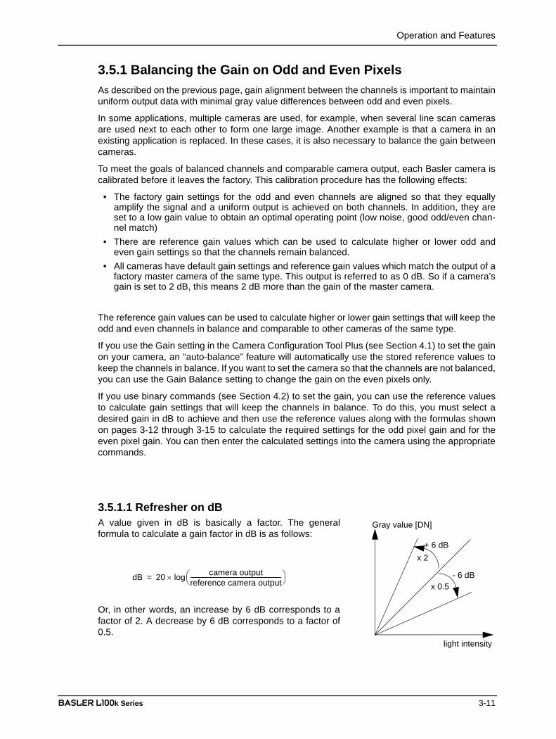
3.5.1.1 Refresher on dBA value given in dB is basically a factor. The generalformula to calculate a gain factor in dB is as follows:
Or, in other words, an increase by 6 dB corresponds to afactor of 2. A decrease by 6 dB corresponds to a factor of0.5.
Gray value [DN]
light intensity
+ 6 dB
- 6 dB
x 2
x 0.5dB 20 camera output
reference camera output-----------------------------------------------------------------⎝ ⎠
⎛ ⎞log×=
Operation and Features
3-12 BASLER L100k Series
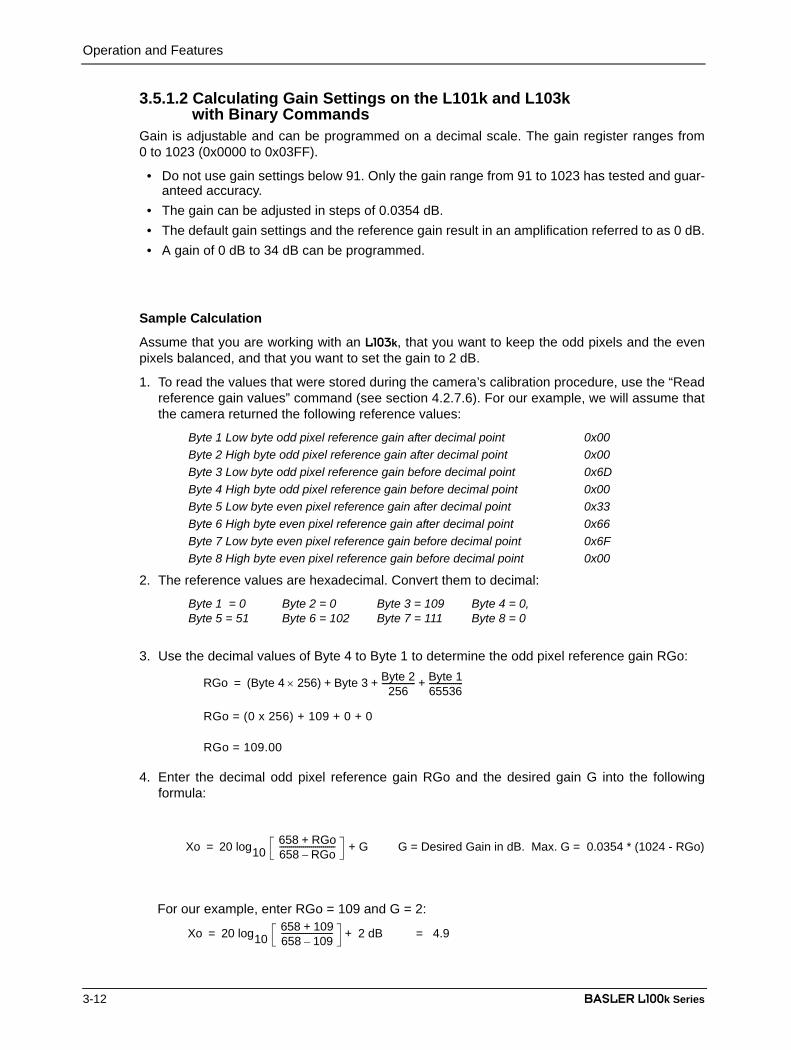
DRAFT3.5.1.2 Calculating Gain Settings on the L101k and L103k
with Binary CommandsGain is adjustable and can be programmed on a decimal scale. The gain register ranges from0 to 1023 (0x0000 to 0x03FF).
• Do not use gain settings below 91. Only the gain range from 91 to 1023 has tested and guar-anteed accuracy.
• The gain can be adjusted in steps of 0.0354 dB.• The default gain settings and the reference gain result in an amplification referred to as 0 dB.• A gain of 0 dB to 34 dB can be programmed.
Sample Calculation
Assume that you are working with an L103k, that you want to keep the odd pixels and the evenpixels balanced, and that you want to set the gain to 2 dB.
1. To read the values that were stored during the camera’s calibration procedure, use the “Readreference gain values” command (see section 4.2.7.6). For our example, we will assume thatthe camera returned the following reference values:
Byte 1 Low byte odd pixel reference gain after decimal point 0x00Byte 2 High byte odd pixel reference gain after decimal point 0x00Byte 3 Low byte odd pixel reference gain before decimal point 0x6DByte 4 High byte odd pixel reference gain before decimal point 0x00Byte 5 Low byte even pixel reference gain after decimal point 0x33Byte 6 High byte even pixel reference gain after decimal point 0x66Byte 7 Low byte even pixel reference gain before decimal point 0x6FByte 8 High byte even pixel reference gain before decimal point 0x00
2. The reference values are hexadecimal. Convert them to decimal:
Byte 1 = 0 Byte 2 = 0 Byte 3 = 109 Byte 4 = 0, Byte 5 = 51 Byte 6 = 102 Byte 7 = 111 Byte 8 = 0
3. Use the decimal values of Byte 4 to Byte 1 to determine the odd pixel reference gain RGo:
RGo = (0 x 256) + 109 + 0 + 0
RGo = 109.00
4. Enter the decimal odd pixel reference gain RGo and the desired gain G into the followingformula:
For our example, enter RGo = 109 and G = 2:
RGo (Byte 4 256) Byte 3 Byte 2256
----------------- Byte 165536-----------------+ + +×=
Xo 20 log10658 RGo+658 RGo–---------------------------- + G= G = Desired Gain in dB. Max. G = 0.0354 * (1024 - RGo)
Xo 20 log10658 109+658 109–-------------------------- 2 dB+= = 4.9

Operation and Features
BASLER L100k Series 3-13
DRAFT5. Calculate the values RGe and Xe for the even channel using the same method as in steps 1,
2, 3, and 4. Use the decimal values of Byte 8 to Byte 5 to determine the even pixel referencegain RGe. RGe is 111.40 in this example, the value for Xe is 4.97.
6. Convert the results to decimal using the appropriate formula a) or b):
Since Xo is 4.9 and thus definitely less than 14.27, we need formula a):
Odd pixel gain setting = 180.8. Round to 181.
7. Calculate the even gain setting in the same way. It is 183 in this example.
8. Convert the results to hexadecimal:
Odd pixel gain setting of 181 decimal = 0x00B5Even pixel gain setting of 183 decimal = 0x00B7
9. Use the odd pixel gain and even pixel gain binary commands to set the odd and even gain tothe calculated values.
After you use the commands to enter the calculated values, the camera will be operating at 2 dBwith respect to the master camera. The odd and even pixels will be balanced.
You may get a better odd/even match by increasing or decreasing either the odd or theeven gain by one.
Since the black level is very stable, you do not need to adjust the offset when youchange the gain.
Odd pixel gain setting658 10×
Xo20 --------
⎝ ⎠⎜ ⎟⎛ ⎞
658–
1 10+Xo20-------
------------------------------------------------------ Where Xo 0.0354 * (512 - RGo)<=a)
Odd pixel gain setting Xo0.0354------------------ Where Xo 0.0354 * (512 - RGo)≥=b)
Odd pixel gain setting658 10×
4.920--------
⎝ ⎠⎜ ⎟⎛ ⎞
658–
1 10+4.920--------
------------------------------------------------------=a)
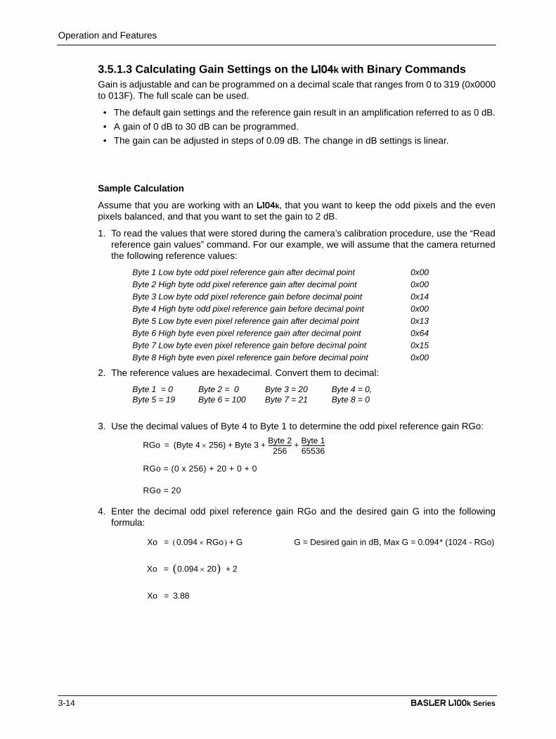
Operation and Features
3-14 BASLER L100k Series
DRAFT3.5.1.3 Calculating Gain Settings on the L104k with Binary CommandsGain is adjustable and can be programmed on a decimal scale that ranges from 0 to 319 (0x0000to 013F). The full scale can be used.
• The default gain settings and the reference gain result in an amplification referred to as 0 dB.• A gain of 0 dB to 30 dB can be programmed.• The gain can be adjusted in steps of 0.09 dB. The change in dB settings is linear.
Sample Calculation
Assume that you are working with an L104k, that you want to keep the odd pixels and the evenpixels balanced, and that you want to set the gain to 2 dB.
1. To read the values that were stored during the camera’s calibration procedure, use the “Readreference gain values” command. For our example, we will assume that the camera returnedthe following reference values:
Byte 1 Low byte odd pixel reference gain after decimal point 0x00Byte 2 High byte odd pixel reference gain after decimal point 0x00Byte 3 Low byte odd pixel reference gain before decimal point 0x14Byte 4 High byte odd pixel reference gain before decimal point 0x00Byte 5 Low byte even pixel reference gain after decimal point 0x13Byte 6 High byte even pixel reference gain after decimal point 0x64Byte 7 Low byte even pixel reference gain before decimal point 0x15Byte 8 High byte even pixel reference gain before decimal point 0x00
2. The reference values are hexadecimal. Convert them to decimal:
Byte 1 = 0 Byte 2 = 0 Byte 3 = 20 Byte 4 = 0, Byte 5 = 19 Byte 6 = 100 Byte 7 = 21 Byte 8 = 0
3. Use the decimal values of Byte 4 to Byte 1 to determine the odd pixel reference gain RGo:
RGo = (0 x 256) + 20 + 0 + 0
RGo = 20
4. Enter the decimal odd pixel reference gain RGo and the desired gain G into the followingformula:
RGo (Byte 4 256) Byte 3 Byte 2256
----------------- Byte 165536-----------------+ + +×=
Xo 0.094 RGo×( ) G G = Desired gain in dB, Max G = 0.094* (1024 - RGo)+=
Xo (0.094 20) × 2+=
Xo 3.88=

Operation and Features
BASLER L100k Series 3-15
DRAFT5. Calculate the values RGe and Xe for the even channel using the same method as in steps 3
and 4. Use the decimal values of Byte 8 to Byte 5 to determine the even pixel reference gainRGe:
RGe is 21.39 in this example, the value for Xe is 4.01.
6. Convert the results to decimal:
Odd pixel gain setting = 41.28
Round to 41.
7. Calculate the even gain setting in the same way. It is 43 in this example.
8. Convert the results to hexadecimal:
Odd pixel gain setting of 41 decimal = 0x0029Even pixel gain setting of 43 decimal = 0x002B
9. Use the odd pixel gain and even pixel gain binary commands to set the odd and even gain tothe calculated values.
After you use the commands to enter the calculated values, the camera will be operating at 2 dBwith respect to the reference camera. The odd and even pixels will be balanced.
You may get a better odd/even match by increasing or decreasing either the odd or theeven gain by one.
Since the black level is very stable, you do not need to adjust the offset when youchange the gain.
RGe (Byte 8 256) Byte 7 Byte 6256
----------------- Byte 565536-----------------+ + +×=
Odd pixel gain setting Xo 0.094---------------=
Odd pixel gain setting 3.880.094---------------=
Operation and Features
3-16 BASLER L100k Series
DRAFT3.5.2 Setting the OffsetYou can use the Offset setting in the Camera Configuration Tool Plus (see Section 4.1) to set theoffst on your camera. When you change the Offset setting, the CCT+ will automatically changethe offset on the odd pixels and on the even pixels by the same amount. If you want to set thecamera so that the offset on each channel is different, you can use the Offset Balance setting tochange the offset on the even pixels only.
You can also use the Odd Pixel Offset binary command to set the offset for the odd pixels and theEven Pixel Offset binary command to set the offset for the even pixels (see Sections 4.2.4.12 and4.2.4.14). The odd pixel and even pixel offset settings can be programmed on a decimal scale thatranges from 0 to 255 (0x0000 to 0x00FF).
If the camera is operating in 10 bit output mode, an increase of 4 (decimal) in the odd pixel settingwill result in a positive offset of 1 in the digital values output for the odd pixels of the sensor. Anincrease of 4 (decimal) in the even pixel setting will result in a positive offset of 1 in the digitalvalues output for the even pixels of the sensor.
If the camera is operating in 8 bit output mode, an increase of 16 (decimal) in the odd pixel settingwill result in a positive offset of 1 in the digital values output for odd pixels of the sensor. Anincrease of 16 (decimal) in the even pixel setting will result in a positive offset of 1 in the digitalvalues output for the even pixels of the sensor.

Operation and Features
BASLER L100k Series 3-17
DRAFT3.6 Shading Correction
In theory, when the camera captures an image of a uniform object, the values output from thepixels in the camera should be uniform. In practice, however, variations in optics and lighting cancause the camera output to be non-uniform even when the camera is viewing a uniform object.The L100k camera is equipped with a shading correction feature that allows the camera to correctthe captured image for variations caused by optics and lighting.
The camera corrects for shading variations by applying a “shading correction table” to eachcaptured image. Before you enable the shading correction feature, you must create a shadingcorrection table and upload it to the camera. You can use either the Camera Configuration ToolPlus (CCT+) or binary commands to create and upload the table and to enable the shadingcorrection feature. See Section 3.6.2 for instructions on using the CCT+ to perform these functionsand Section 3.6.3 for instructions on performing them with binary commands.
Please note that when using Shading Correction, you must follow the guidelines listed in Section3.6.1.
3.6.1 Shading Correction GuidelinesWhen using shading correction, make sure that you take the following guidelines into account:
• Shading correction is only available in 8-bit output mode. Activating 10-bit output mode willdisable shading correction.
• Any time that you make a change to optics or lighting, you must create a new shading correc-tion table. You must also create a new shading table any time that you change the gain set-tings on the camera or the digital shift.Using an out of date shading correction table can result in poor quality images.
• During the process of creating a shading table, you will capture lines while the camera isfocused on a uniform gray target. The ratio of the value for the lightest pixel in the capturedlines to the value for the darkest pixel in the captured lines must not be more than 2/1. If it isgreater than 2/1, the shading correction feature will not be able to fully correct the shadingvariations.
3.6.2 Using the CCT+ to Work With Shading CorrectionTo create and upload a shading correction table and to enable shading correction using the CCT+:
1. Open the CCT+. Use the Shading Correction setting in the Output parameter group to setshading correction to off (Shading Correction must be off when you capture data for theshading table).
2. Use the Video Data Output Mode setting to set your camera for Single 8 bit or Dual 8 bitoutput mode. (Before selecting Dual 8 bit mode, make sure that your frame grabber iscapable of supporting dual output.)
3. Place a uniform gray target in the camera‘s field of view.4. Make sure that your optics and lighting are set to their normal operating conditions. Optics
and lighting must be set before you capture any data.5. Make sure that your grabber is properly configured to accept the output mode that you
selected in step 2.6. Use the software included with your frame grabber to capture and store at least 100 lines of
data to a file. Save the resulting file as an image in GIF, JPG, JPEG, or PNG format. (The

Operation and Features
3-18 BASLER L100k Series
DRAFTsoftware included with most frame grabbers includes a function that will allow you to captureand store a specific number of lines and to save the captured lines as an image file.)
7. In many cases, when a frame grabber is receiving pixel data for a captured line, the grabberdrops the data for the first few pixels. Since you are using captured pixel data from the framegrabber to create the shading table, you must make sure that you know how many pixelsyour grabber is dropping. You can use Test Image One (see Section 3.9.1), consult the documentation for your framegrabber, or speak to your frame grabber manufacturer to determine the number of pixels thatthe grabber drops at the start of each line.
Determine the number of pixels that your grabber drops and make note of it.
8. In the CCT+, double-click on “Upload Correction Data”. A Specify Shading Correction Imagewindow will open.
9. Click on the button and an Open Shading Correction Image window will appear. Use thewindow to navigate to the image file that you stored in step 6 and then click the Open button.
10. If you want the shading correction table to be stored in the camera’s non-volatile memorywhen you upload it to the camera, make sure that the Permanently store shading data inthe camera box is checked. (See the notebox below for more information.)
11. In the Offset box, enter the number of pixels that the frame grabber drops from each line.12. Click the Load to camera button. The CCT+ will use the image data in the file you selected
to create a shading table and then will upload the table to the camera.If this process is successful, a message will appear informing you about the ratio of the lightestpixel to the darkest pixel in the image .
If the process is not successful, an error message will appear. The usual cause of the error isthat the ratio of the lightest pixel in the image to the darkest pixel is greater than 2/1. Whenthis is the case, the shading feature will not be able to fully correct the shading variations.
13. Once the correction table has been successfully created and uploaded, you can use theshading correction feature. To enable shading correction, use the Shading Correction settingin the CCT+.
Normally, a copy of the shading table is stored in a volatile memory location and a copyis also stored in a non-volatile memory location. When shading correction is enabled,the FPGA in the camera uses the table stored in volatile memory to perform shading cor-rection by applying the correction values in the table to the pixel values for each cap-tured line.
When you store shading correction data to the camera with the CCT+, you can store thedata in both the volatile and the non-volatile memory or in the volatile memory only. Ashading table stored in the non-volatile memory will not be lost when power is switchedoff.
When you upload the shading table and the Permanently store shading data in thecamera box is checked, the table will be loaded to both the non-volatile and the volatilememories. Any table already in these memories will be overwritten.
When you upload the shading table and the Permanently store shading data in thecamera box is not checked, the table will be loaded to the volatile memory only. Thisfeature is useful if you wish to load and test a shading table without overwriting the tablethat is currently stored in the non-volatile memory.

Operation and Features
BASLER L100k Series 3-19
DRAFT3.6.3 Using Binary Commands to Work With Shading CorrectionWhen using binary commands to create and upload a shading table and to enable the shadingcorrection feature, follow the instructions given in Sections 3.6.3.1 through 3.6.3.3.
3.6.3.1 Creating a Shading Correction TableWhen shading correction is active on the L100k camera, each pixel value is multiplied by acorrection factor and the corrected pixel values are transferred out of the camera.
There is an individual correction factor for each of the sensor’s pixels, that is, there are 1024correction factors for cameras with a 1024 pixel sensor or 2048 for cameras with a 2048 pixelsensor.
The correction factors are multipliers that are applied to the pixels in each captured line to makethem better represent what they would be if no shading was present.
The correction factors are determined by capturing an image of a uniform target and then for eachpixel, calculating the multiplier that would make the pixel value equal to the lightest pixel in theimage.
Correction factors are floating point numbers. Since floating point numbers cannot be written intothe camera, each correction factor must be converted into an integer value that represents thecorrection factor. Here is the formula that is used for conversion:
The range of possible correction factors is 1 to 1.996 where 1 converts to an integer value of 0and 1.996 converts to an integer value of 255.
The individual integer correction values make up the shading correction table that is uploaded intothe camera. Creating a shading correction table is a three step process: 1) capturing and storing100 lines of image data, 2) calculating shading correction data from the captured data, and 3)writing the correction data to the camera.
Capturing and Storing Image Data
Follow this procedure to capture and store data:
1. Switch off the shading correction using the Shading Correction binary command described inSection 4.2.4.8. (Shading Correction must be disabled when you capture the data).
2. Use the Video Data Output Mode binary command described in Section 4.2.4.1 to set yourcamera into Single 8 bit or Dual 8 bit output mode. Before selecting Dual 8 bit mode, makesure that your frame grabber is capable of supporting dual output.
3. Place a uniform gray target in the camera‘s field of view.4. Make sure that your optics and lighting are set to their normal operating conditions. Optics
and lighting must be set before you capture any data.5. Make sure that your grabber is properly configured to accept the output mode that you
selected in step 2.6. Use the software included with your frame grabber to capture and store 100 lines of data to a
data file. (The software included with most frame grabbers includes a function that will allowyou to capture and store a specific number of lines.)
Correction factor Lightest pixelCurrent pixel-----------------------------------=
Correction factor Correction value 256+256
------------------------------------------------------------=
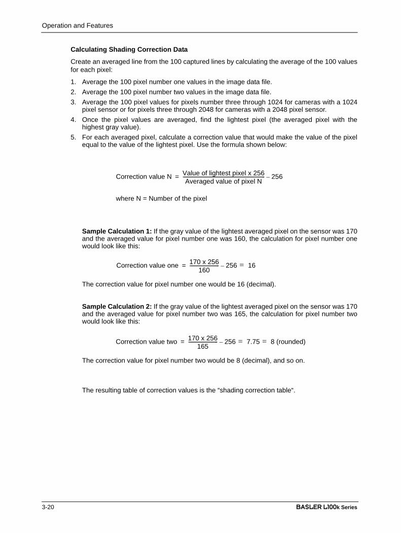
Operation and Features
3-20 BASLER L100k Series
DRAFTCalculating Shading Correction Data
Create an averaged line from the 100 captured lines by calculating the average of the 100 valuesfor each pixel:
1. Average the 100 pixel number one values in the image data file.2. Average the 100 pixel number two values in the image data file.3. Average the 100 pixel values for pixels number three through 1024 for cameras with a 1024
pixel sensor or for pixels three through 2048 for cameras with a 2048 pixel sensor.4. Once the pixel values are averaged, find the lightest pixel (the averaged pixel with the
highest gray value).5. For each averaged pixel, calculate a correction value that would make the value of the pixel
equal to the value of the lightest pixel. Use the formula shown below:
Sample Calculation 1: If the gray value of the lightest averaged pixel on the sensor was 170and the averaged value for pixel number one was 160, the calculation for pixel number onewould look like this:
The correction value for pixel number one would be 16 (decimal).
Sample Calculation 2: If the gray value of the lightest averaged pixel on the sensor was 170and the averaged value for pixel number two was 165, the calculation for pixel number twowould look like this:
The correction value for pixel number two would be 8 (decimal), and so on.
The resulting table of correction values is the “shading correction table“.
Correction value N Value of lightest pixel x 256Averaged value of pixel N
------------------------------------------------------------------------- 256–=
where N = Number of the pixel
Correction value one 170 x 256160
-------------------------- 256 16=–=
Correction value two 170 x 256165
-------------------------- 256 7.75 8 (rounded)==–=
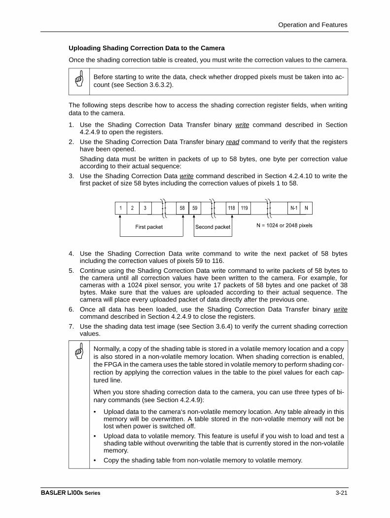
Operation and Features
BASLER L100k Series 3-21
DRAFTUploading Shading Correction Data to the Camera
Once the shading correction table is created, you must write the correction values to the camera.
The following steps describe how to access the shading correction register fields, when writingdata to the camera.
1. Use the Shading Correction Data Transfer binary write command described in Section4.2.4.9 to open the registers.
2. Use the Shading Correction Data Transfer binary read command to verify that the registershave been opened.Shading data must be written in packets of up to 58 bytes, one byte per correction valueaccording to their actual sequence:
3. Use the Shading Correction Data write command described in Section 4.2.4.10 to write thefirst packet of size 58 bytes including the correction values of pixels 1 to 58.
4. Use the Shading Correction Data write command to write the next packet of 58 bytesincluding the correction values of pixels 59 to 116.
5. Continue using the Shading Correction Data write command to write packets of 58 bytes tothe camera until all correction values have been written to the camera. For example, forcameras with a 1024 pixel sensor, you write 17 packets of 58 bytes and one packet of 38bytes. Make sure that the values are uploaded according to their actual sequence. Thecamera will place every uploaded packet of data directly after the previous one.
6. Once all data has been loaded, use the Shading Correction Data Transfer binary writecommand described in Section 4.2.4.9 to close the registers.
7. Use the shading data test image (see Section 3.6.4) to verify the current shading correctionvalues.
Before starting to write the data, check whether dropped pixels must be taken into ac-count (see Section 3.6.3.2).
Normally, a copy of the shading table is stored in a volatile memory location and a copyis also stored in a non-volatile memory location. When shading correction is enabled,the FPGA in the camera uses the table stored in volatile memory to perform shading cor-rection by applying the correction values in the table to the pixel values for each cap-tured line.
When you store shading correction data to the camera, you can use three types of bi-nary commands (see Section 4.2.4.9):
• Upload data to the camera‘s non-volatile memory location. Any table already in thismemory will be overwritten. A table stored in the non-volatile memory will not belost when power is switched off.
• Upload data to volatile memory. This feature is useful if you wish to load and test ashading table without overwriting the table that is currently stored in the non-volatilememory.
• Copy the shading table from non-volatile memory to volatile memory.

Operation and Features
3-22 BASLER L100k Series
DRAFT3.6.3.2 Taking Dropped Pixels into AccountIn many cases, when a frame grabber is receiving pixel data for a captured line, the grabber dropsthe data for the first few pixels. Since you have used captured pixel data from the frame grabberto create the shading table, you must make sure that at the beginning of your shading data, youfill in a dummy correction value for every pixel dropped by the frame grabber.
You can use Test Image One (see Section 3.9.1), consult the documentation for your framegrabber, or speak to your frame grabber manufacturer to determine the number of pixels that thegrabber misses at the start of each line. Use this value to determine the dummy correction valuesthat must be added to the sdahing correction data that you upload to the camera. For example, ifyour grabber misses 5 pixels at the beginning of each line, add 5 dummy correction values beforethe actual correction values (see Figure 3-9).
3.6.3.3 Enabling Shading CorrectionTo enable the shading correction feature, use the Shading Correction binary command describedin Section 4.2.4.8.
Figure 3-9: Adding Dummy Correction Values
Operation and Features
BASLER L100k Series 3-23
DRAFT3.6.4 The Shading Data Test ImageL100k cameras offer a “shading data” test image. When the camera is operating in this mode, itoutputs the values in the shading correction table as though they were a line of image data. If youplace the camera in the shading data test image mode and you capture a line, you can examinethe values in the captured line to see what is stored in the shading correction table.
The shading data test image can be enabled using either the Camera Configuration Tool Plus (seeSection 4.1) or binary commands (see Section 4.2).
With the Camera Configuration Tool Plus, you use the Shading Correction setting in the Outputparameter group to enable this mode.
With binary commands, you use the Shading Correction command (see Section 4.2.4.8).

Operation and Features
3-24 BASLER L100k Series
DRAFT3.7 Digital Shift
The “digital shift” feature allows you to change the group of bits that is output from each ADC.Using the digital shift feature will effectively multiply the output of the camera by 2 times, 4 timesor 8 times. Section 3.7.1 describes how digital shift works when the camera is operating in a 10bit output mode and Section 3.7.2 describes how digital shift works when the camera is operatingin an 8 bit output mode.
Please note the precautions you must observe to effectively use this feature (see Section 3.7.3).
You can set digital shift using either the Camera Configuration Tool Plus (see Section 4.1) orbinary commands (see Section 4.2).
With the Camera Configuration Tool Plus, you use the Digital Shift setting in the Output parametergroup.
With binary commands you use the Digital Shift command.
3.7.1 Digital Shift in 10 bit Output Mode
No ShiftAs mentioned in Section 3.1, the L100k uses 10 bitADCs to digitize the output from the CCD sensor.When the camera is operating in 10 bit outputmode, by default, the camera transmits the 10 bitsthat are output from each ADC.
Shift OnceWhen the camera is set to shift once, the outputfrom the camera will include bit 8 through bit 0 fromeach ADC along with a zero as an LSB.
The result of shifting once is that the output of thecamera is effectively doubled. For example,assume that the camera is set for no shift, that it isviewing a uniform white target, and that under theseconditions the reading for the brightest pixel is 100.If you changed the digital shift setting to shift once,the reading would increase to 200.
Note that if bit 9 is set to 1, all of the other bits will automatically be set to 1. Thismeans that you should only use the shift once setting when your pixel readings in10 bit mode with no digital shift are all below 512.
Since the shift once setting requires that the least significant bit is always a "0" andnever a "1", no odd gray values can be output. The gray value scale will only includegray values of 2, 4, 6 and so forth. The absence of gray values is commonly referredto as "Missing Codes".
bit9
bit8
bit7
bit6
bit5
bit4
bit3
bit2
bit1
bit0
MSB
LSB
ADC
Not Shifted
“0”bit9
bit8
bit7
bit6
bit5
bit4
bit3
bit2
bit1
bit0
MSB
LSB
ADC
Shifted Once

Operation and Features
BASLER L100k Series 3-25
DRAFTShift TwiceWhen the camera is set to shift twice, the outputfrom the camera will include bit 7 through bit 0from each ADC along with two zeros as LSBs.
The result of shifting twice is that the output of thecamera is effectively multiplied by four. Forexample, assume that the camera is set for noshift, that it is viewing a uniform white target, andthat under these conditions the reading for thebrightest pixel is 100. If you changed the digitalshift setting to shift twice, the reading wouldincrease to 400.
Shift Three TimesWhen the camera is set to shift three times,the output from the camera will include bit 6through bit 0 from each ADC along withthree zeros as LSBs.
The result of shifting three times is that theoutput of the camera is effectively multipliedby eight. For example, assume that thecamera is set for no shift, that it is viewing auniform white target, and that under theseconditions the reading for the brightest pixelis 100. If you changed the digital shift settingto shift three times, the reading wouldincrease to 800.
Note that if bit 9 or bit 8 is set to 1, all of the other bits will automatically be set to 1.This means that you should only use the shift twice setting when your pixel readingsin 10 bit mode with no digital shift are all below 256.
Since the shift twice setting requires that the two least significant bits are always"0" and never "1", the gray value scale will only include every 4th gray value. Forexample, 4, 8, 16 and so forth.
Note that if bit 9, bit 8 or bit 7 is set to 1, all of the other bits will automatically be setto 1. This means that you should only use the shift three times setting when yourpixel readings in 10 bit mode with no digital shift are all below 128.
Since the shift three times setting requires that the three least significant bits arealways "0" and never "1", the gray value scale will only include every 8th gray value.For example, 8, 16, 24 and so forth.
“0”bit9
bit8
bit7
bit6
bit5
bit4
bit3
bit2
bit1
bit0
MSB
ADC
Shifted Twice
“0”
LSB
“0”bit9
bit8
bit7
bit6
bit5
bit4
bit3
bit2
bit1
bit0
MSB
ADC
Shifted 3 Times
“0” “0”
LSB
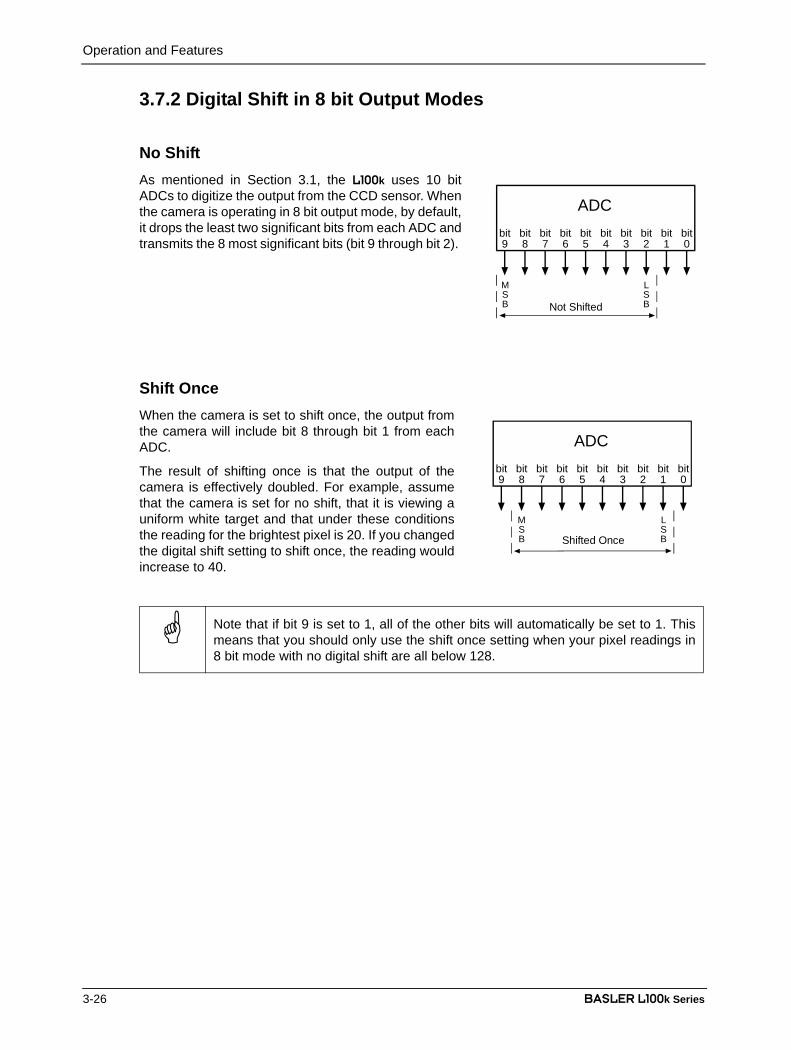
Operation and Features
3-26 BASLER L100k Series
DRAFT3.7.2 Digital Shift in 8 bit Output Modes
No ShiftAs mentioned in Section 3.1, the L100k uses 10 bitADCs to digitize the output from the CCD sensor. Whenthe camera is operating in 8 bit output mode, by default,it drops the least two significant bits from each ADC andtransmits the 8 most significant bits (bit 9 through bit 2).
Shift OnceWhen the camera is set to shift once, the output fromthe camera will include bit 8 through bit 1 from eachADC.
The result of shifting once is that the output of thecamera is effectively doubled. For example, assumethat the camera is set for no shift, that it is viewing auniform white target and that under these conditionsthe reading for the brightest pixel is 20. If you changedthe digital shift setting to shift once, the reading wouldincrease to 40.
Note that if bit 9 is set to 1, all of the other bits will automatically be set to 1. Thismeans that you should only use the shift once setting when your pixel readings in8 bit mode with no digital shift are all below 128.
bit9
bit8
bit7
bit6
bit5
bit4
bit3
bit2
bit1
bit0
MSB
LSB
ADC
Not Shifted
bit9
bit8
bit7
bit6
bit5
bit4
bit3
bit2
bit1
bit0
MSB
LSB
ADC
Shifted Once

Operation and Features
BASLER L100k Series 3-27
DRAFTShift TwiceWhen the camera is set to shift twice, the output fromthe camera will include bit 7 through bit 0 from eachADC.
The result of shifting twice is that the output of thecamera is effectively multiplied by four. For example,assume that the camera is set for no shift, that it isviewing a uniform white target, and that under theseconditions the reading for the brightest pixel is 20. Ifyou changed the digital shift setting to shift twice, thereading would increase to 80.
Shift Three TimesWhen the camera is set to shift three times, theoutput from the camera will include bit 6 throughbit 0 from each ADC along with a zero as theLSB.
The result of shifting three times is that the outputof the camera is effectively multiplied by eight.For example, assume that the camera is set forno shift, that it is viewing a uniform white targetand that under these conditions the reading forthe brightest pixel is 20. If you changed the digitalshift setting to shift three times, the reading wouldincrease to 160.
Note that if bit 9 or bit 8 is set to 1, all of the other bits will automatically be set to 1.This means that you should only use the shift twice setting when your pixel readingsin 8 bit mode with no digital shift are all below 64.
Note that if bit 9, bit 8 or bit 7 is set to 1, all of the other bits will automatically be setto 1. This means that you should only use the shift once setting when your pixelreadings in 8 bit mode with no digital shift are all below 32.
Since the shift three times setting requires that the least significant bit is always a"0" and never a "1", no odd gray values can be output. The gray value scale will onlyinclude gray values of 2, 4, 6 and so forth.
bit9
bit8
bit7
bit6
bit5
bit4
bit3
bit2
bit1
bit0
MSB
ADC
Shifted Twice
LSB
“0”bit9
bit8
bit7
bit6
bit5
bit4
bit3
bit2
bit1
bit0
MSB
ADC
Shifted 3 Times
LSB

Operation and Features
3-28 BASLER L100k Series
DRAFT3.7.3 Precautions When Using Digital ShiftThere are several checks and precautions that you must follow before using the digital shiftfeature. The checks and precautions differ depending on whether you will be using the camera in10 bit output mode or in 8 bit output mode.
If you will be using the camera in 10 bit output mode, make this check:
1. Use binary commands or the Camera Configuration Tool Plus (CCT+) to put the camera in10 bit output mode.
2. Use binary commands or the CCT+ to set the camera for no digital shift.3. Check the output of the camera under your normal lighting conditions with no digital shift and
note the readings for the brightest pixels.• If any of the readings are above 512, do not use digital shift.• If all of the readings are below 512, you can safely use the 2X digital shift setting.• If all of the readings are below 256, you can safely use the 2X or 4X digital shift setting.• If all of the readings are below 128, you can safely use the 2X, 4X or 8X digital shift setting.
If you will be using the camera in 8 bit output mode, make this check:
1. Use binary commands or the Camera Configuration Tool Plus (CCT+) to put the camera in 8bit output mode.
2. Use the binary commands or the CCT+ to set the camera for no digital shift.3. Check the output of the camera under your normal lighting conditions with no digital shift and
note the readings for the brightest pixels.• If any of the readings are above 128, do not use digital shift.• If all of the readings are below 128, you can safely use the 2X digital shift setting.• If all of the readings are below 64, you can safely use the 2X or 4X digital shift setting.• If all of the readings are below 32, you can safely use the 2X, 4X or 8X digital shift setting.

Operation and Features
BASLER L100k Series 3-29
DRAFT3.8 Area of Interest (AOI)
The area of interest feature allows you to specify a portion of the CCD array and during operation,all pixels are transferred out of the camera but only the pixel information from the specified portionis signalled as valid to the frame grabber. Pixels outside of the AOI are read out of the sensor, buttransferred to the frame grabber as black pixels and signalled as invalid to the grabber.
The size of the area of interest is defined by declaring a starting pixel and a length in pixels (seeFigure 3-10). For example, if you specify the starting pixel as 10 and the length in pixels as 15, thecamera will output all pixels from the array but only pixels 10 through 24 will be valid.
Figure 3-10: Area of Interest
The number of transferred pixels does not decrease when the area of interest feature is used.
The maximum achieveable line rate does not increase when the area of interest feature is used.
Validity of pixels is signalled using the line valid bit.
On the pixel clock cycle where AOI data transmission begins, the line valid bit will become high.For example, if you specify the starting pixel as 5, the line valid bit will become high on the clockcycle where pixel 5 is transmitted (see Figure 3-11). After all of the pixels in the AOI have beentransmitted, the line valid bit will become low indicating that valid line data is no longer beingtransmitted.
Figure 3-11: Single 10 Bit or Single 8 Bit Output Mode with Edge or Level Controlled Exposure
If you use a frame grabber which does not take the falling edge of the line valid bitinto account, you must also set the frame grabber to the number of pixels in the areaof interest. For example, when you have an area of interest of 500 pixels, you mustalso set the grabber to 500 pixels. Otherwise, the grabber will show no effect.
30 29 28 27 26 25 24 23 22 21 20 19 18 17 16 15 14 13 12 11 10 9 8 7 6 5 4 3 2 1
Length in Pixels
Line of Pixelsin the CCD
StartingPixel

Operation and Features
3-30 BASLER L100k Series
DRAFT
You can set the area of interest using either the Camera Configuration Tool Plus (see Section 4.1)or binary commands (see Section 4.2).
With the Camera Configuration Tool Plus, you use the AOI Starting Pixel and the AOI Lengthsettings in the AOI parameter group to set the area of interest.
With binary commands you use the Area of Interest Starting Pixel and Area of Interest Length inPixel commands.
In normal operation, the camera is set to use all of the pixels in the array. To use allof the pixels, the starting pixel should be set to 1 and the length in pixels to 1024 forcameras with a 1024 pixel sensor or 2048 for cameras with a 2048 pixel sensor.

Operation and Features
BASLER L100k Series 3-31
DRAFT3.9 Test Images
The test image mode is used to check the camera’s basic functionality and its ability to transmitan image via the video data cable. A test image can be used for service purposes and for failurediagnostics. In test mode, the image is generated with a software program and the camera’s digitaldevices and does not use the optics, CCD sensor, VGCs or ADCs. Two test images are available(see Sections 3.9.1 and 3.9.2).
When using a test image, please also follow the guidelines given in Section 3.9.3.
In addition to the two standard test images, the L100k also offers a shading data test image mode(see Section 3.6.4).
You can enable the test images using either the Camera Configuration Tool Plus (see Section 4.1)or use binary commands (see Section 4.2).
With the Camera Configuration Tool Plus, you use the Test Image setting in the Output parametergroup to set the test image.
With binary commands, you use the Test Image command (see Section 4.2.5).
3.9.1 Test Image OneTest image one is formed with an odd/even gray scale gradient that ranges from 0 to 255 and re-peats every 512 pixels as shown in Figure 3-12. The odd pixel gradient starts at 0 and steps up,that is, the gray value of pixel 1 is 0, the gray value of pixel 3 is 1, the gray value of pixel 5 is 2,and so forth. The even gradient starts at 255 and steps down, that is, the gray value of pixel 2 is255, the gray value of pixel 4 is 254, the gray value of pixel 6 is 253, and so forth.
At pixels 256 and 257, the gray value for both pixels is 128. At pixels 511 and 512, a white oddpixel is next to a black even pixel. At pixels 513 and 514, a black odd pixel is next to a white evenpixel. To the human eye, the gradient appears to be a varying gray field with a white vertical lineevery 512 pixels.
Figure 3-12: Formation of Test Image One
Figure 3-13: Test Image One
1 512 1024
255
evenodd
0
[gray level]
[pixel number]1536 2048
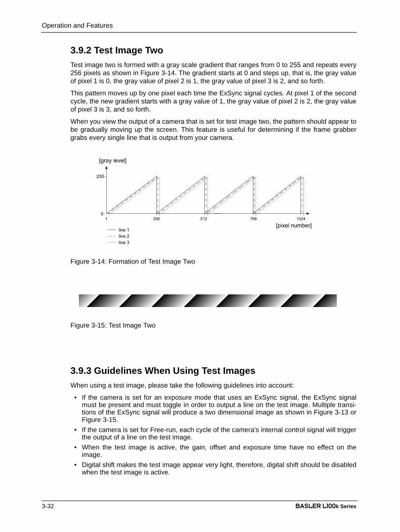
Operation and Features
3-32 BASLER L100k Series
DRAFT3.9.2 Test Image TwoTest image two is formed with a gray scale gradient that ranges from 0 to 255 and repeats every256 pixels as shown in Figure 3-14. The gradient starts at 0 and steps up, that is, the gray valueof pixel 1 is 0, the gray value of pixel 2 is 1, the gray value of pixel 3 is 2, and so forth.
This pattern moves up by one pixel each time the ExSync signal cycles. At pixel 1 of the secondcycle, the new gradient starts with a gray value of 1, the gray value of pixel 2 is 2, the gray valueof pixel 3 is 3, and so forth.
When you view the output of a camera that is set for test image two, the pattern should appear tobe gradually moving up the screen. This feature is useful for determining if the frame grabbergrabs every single line that is output from your camera.
Figure 3-14: Formation of Test Image Two
Figure 3-15: Test Image Two
3.9.3 Guidelines When Using Test ImagesWhen using a test image, please take the following guidelines into account:
• If the camera is set for an exposure mode that uses an ExSync signal, the ExSync signalmust be present and must toggle in order to output a line on the test image. Multiple transi-tions of the ExSync signal will produce a two dimensional image as shown in Figure 3-13 orFigure 3-15.
• If the camera is set for Free-run, each cycle of the camera’s internal control signal will triggerthe output of a line on the test image.
• When the test image is active, the gain, offset and exposure time have no effect on theimage.
• Digital shift makes the test image appear very light, therefore, digital shift should be disabledwhen the test image is active.

Operation and Features
BASLER L100k Series 3-33
DRAFT3.10 Configuration Sets
The camera’s adjustable parameters are stored inconfiguration sets and each configuration set containsall of the parameters needed to control the camera.There are three different types of configuration sets: theWork Set, the Factory Set, and User Sets.
Work Set
The Work Set contains the current camera settings andthus determines the camera’s present performance,that is, what your image currently looks like. The WorkSet is stored in the camera RAM. The configurationparameters in the Work Set can be altered directlyusing the Camera Configuration Tool or using binaryprogramming commands.
Factory Set
When a camera is manufactured, a test set up is performed on the camera and an optimizedconfiguration is determined. The Factory Set contains the camera’s factory optimizedconfiguration. The Factory Set is stored in non-volatile memory on the EEPROM and can not bealtered.
User Sets
User Sets are also stored in the non-volatile EEPROM of the camera. The camera has 15 UserSets. Each User Set initially contains factory settings but User Sets can be modified. Modificationis accomplished by making changes to the Work Set and then copying the Work set into one ofthe User Sets. The Camera Configuration Tool or binary commands can be used to copy the WorkSet into one of the User Sets.
Startup Pointer
When power to the camera is switched off, the Work set in the RAM is lost. At the next power on,a configuration set is automatically copied into the Work Set. The Startup Pointer is used to specifywhich of the configuration sets stored in the EEPROM will be copied into the Work Set at poweron. The Startup Pointer is initially set so that the Factory Set is loaded into the Work Set at poweron. This can be changed using the Camera Configuration Tool or binary commands. The StartupPointer can be set to the Factory Set or to any one of the User Sets. So, for example, if the StartupPointer is set to User Set 13, then User Set 13 will be copied into the Work Set at power on.
You can work with configuration sets and the startup pointer using either the CameraConfiguration Tool Plus (see Section 4.1) or binary commands (see Section 4.2.8).
With the Camera Configuration Tool Plus, you can use the Camera selection in the File menu tocopy the Work Set to a User Set, to copy a User Set or the Factory Set to the Work Set, or to setthe Startup Pointer.
With binary commands, you use the Copy Work Set to User Set command, the Copy Factory Setor User Set to Work Set command, and the Select Startup Pointer command to manipulateconfiguration sets.
Figure 3-16: Config Sets
Operation and Features
3-34 BASLER L100k Series
DRAFT3.11 Camera Temperature
L100k series cameras include a sensor that measures the temperature on one of the electronicboards inside of the camera. The sensor’s readings allow you to monitor whether ventilation isworking correctly.
You can use the Read Camera Temperature binary command to read out the current temperature(see Section 4.2.7.9).
3.12 Camera StatusL100k series cameras monitor their status by performing a regular series of self checks. Thecurrent status of a camera can be viewed in several ways:
• with the Camera Configuration Tool Plus (see Section 4.1). You use the Status indicator inthe Camera Information parameter group to see if any error codes are present.
• with binary commands. You can use the Camera Status command (see Section 4.2.9) tocheck if the camera has detected any errors.
• by checking the LED on the back of the camera. If certain error conditions are present, theLED will flash (see Section 6.1).
Warning!
The reading for the internal camera temperature must not exceed 90° C.If the internal camera temperature rises higher than 90° C, electronic com-ponents may be damaged.
To prevent internal heat build-up, observe the ventilation requirements de-scribed in Section 1.3.2.
Configuring the Camera
BASLER L100k Series 4-1
DRAFT
4 Configuring the Camera
L100k series cameras come factory-set so that they will work properly for most applications withminor changes to the camera configuration. For normal operation, the following parameters areusually configured by the user:
• Exposure time control mode• Exposure time (for ExSync programmable mode or free-run programmable mode)
To customize operation for your particular application, the following parameters can also beconfigured:
• Gain• Offset• Shading Correction• Area of Interest• Digital Shift
L100k series cameras are programmable via the serial port on the frame grabber. Two methodscan be used to change the cameras’s settings. The first and easier approach is to change thesettings using the Camera Configuration Tool Plus. See Section 4.1 and the configuration tool’son-line help file for instructions on using the configuration tool. You can also change the camera’ssettings directly from your application using binary commands. Section 4.2 lists the binarycommands and provides instructions for their use.
Configuring the Camera
4-2 BASLER L100k Series
DRAFT4.1 Configuring the Camera with the Camera
Configuration Tool Plus (CCT+)The Camera Configuration Tool Plus (CCT+) is a Windows™ based program used to easilychange the camera’s settings. The tool communicates via the RS-644 serial connection in theCamera Link interface between the frame grabber and the camera. The tool automaticallygenerates the binary programming commands that are described in Section 4.2. For instructionson installing the tool, see the installation booklet that was shipped with the camera.
This manual assumes that you are familiar with Microsoft Windows and that you have a basicknowledge of how to use programs. If not, please refer to your Microsoft Windows manual.
4.1.1 Opening the Configuration Tool1. Make sure that the properties for the RS-644 serial port on your frame grabber are properly
configured and that the camera has power.2. On the desktop of your computer, click Start, click Programs, click Basler Vision Technolo-
gies, click CCT+, and then click CCT+ to start the CCT+ (default installation).
During start-up, a start-up screen can be seen.
If start-up is successful, the tool will open. To familiarize yourself with using the tool, press theF1 key and look through the online help included with the tool.
If start-up is not successful, the tool will automatically close. If this happens, refer to the CCT+Installation Guide for possible causes.
4.1.2 Closing the Configuration ToolClose the configuration tool by clicking on the button in the upper right corner of the window.

Configuring the Camera
BASLER L100k Series 4-3
DRAFT4.1.3 Configuration Tool BasicsThe RAM memory in the camera contains the set of parameters that controls the current operationof the camera. This set of parameters is known as the Work Set (see Section 3.10). The CCT+ isused to view the present settings for the parameters in the Work Set or to change the settings.
When the CCT+ is opened and a port isselected, it queries the camera and displaysa list of the current settings for theparameters in the Work Set.
To simplify navigation, parameters areorganized in related groups. For example, allparameters related to the camera output canbe found in the Output group (Figure 4-1).
When you click on the plus or minus signbeside a group (+ or -), the parameters inthis group will be shown or hidden,respectively.
To get an overview of all parametersavailable on the connected camera,maximize the CCT+ window and click the +sign beside each group.
The camera parameter names alwaysappear in the left column of the list. Thecurrent setting for each parameter appearsin the right column.
By default, an additional ParameterDescription window is displayed. In thiswindow, you can find basic information onthe selected parameter and if present, onthe dependencies that may exist betweenthe selected parameter and otherparameter(s).
If you make a change to one of the settings, that change will immediately be transmitted from theCCT+ to the camera’s Work Set. Because the parameters in the Work Set control the currentoperation of the camera, you will see an immediate change in the camera’s operation.
By default, the CCT+ automatically updates the displayed settings every 5 seconds. The featurebehind this behavior is called Auto Refresh. If Auto Refresh is not enabled, the display will notupdate when a camera setting is changed using another tool, when power to the camera isswitched off and on, or when the connected camera is exchanged while the CCT+ is displayingthe camera settings. To manually refresh the display, you can use the Refresh button in the topright corner of the tool.
Figure 4-1: CCT+

Configuring the Camera
4-4 BASLER L100k Series
DRAFT
4.1.4 Configuration Tool HelpThe configuration tool includes a complete on-line help file which explains how to change asetting, to copy the Work Set to a User Set, to Copy a User Set or the Factory Set to the Work Set,or to set the Startup Pointer. To access on-line help, press the F1 key whenever the configurationtool is active.
Keep in mind that the Work Set is stored in a volatile memory. Any changes you maketo the Work Set using the configuration tool will be lost when the camera is switchedoff. To save changes you make to the Work Set, open the Camera menu of the config-uration tool and save the modified Work Set into one of the camera’s 15 User Sets. TheUser Sets are stored in non-volatile memory and will not be lost when the camera isswitched off (see Section 3.10).
Alternatively, you can also save the Work Set to the hard disk of your computer andload it from hard disk.
If you want your changes to be loaded into the Work Set at the next power on, go tothe Camera menu and set the Startup Pointer to the User Set where you saved yourchanges.
Configuring the Camera
BASLER L100k Series 4-5
DRAFT4.2 Configuring the Camera with Binary
Programming CommandsConfiguration commands can be issued to the L100k via the RS-644 serial connection in theCamera Link interface between the frame grabber and the camera. Commands are issued usinga binary protocol. With this protocol, data is placed into a frame and sent to the camera. Once thedata is received it is checked for validity. If valid, the data is extracted and the command isexecuted.
If the command issued to the camera was a read command, the camera will respond by placingthe requested data into a frame and sending it to the host computer.
A standard application programmer’s interface (API) for asynchronous serial reading and writingvia the RS-644 port on the frame grabber has been defined in the Camera Link standard(Appendix B, API Functions). All Camera Link compatible frame grabbers provide a softwarelibrary (.dll file) named clser***.dll where *** is specific to the frame grabber vendor. There are fourfunctions within that DLL:
• ISerialInit - Initialize the serial communication for a specific board.• clSerialRead - Read bytes from the camera.• clSerialWrite - Write bytes to the camera.• clSerialClose - Close the serial communication.
To execute the binary programming commands, you can load the DLL for the frame grabber youare using into your programming tool. You can use either the API from the DLL delivered with thegrabber or the Basler CPA driver for executing the binary commands.
The Basler CPA (Camera Port Access) is a software framework which standardizes access to thecamera ports via frame grabbers from different vendors. With the help of the Basler CPA driver,you can read and write blocks of data to and from the camera. The binary command protocol isfully implemented in the CPA driver.
The CPA driver and a Programmers Guide for the driver are both part of Basler’s Classic CameraConfiguration Tool. The Classic Configuration Tool can be downloaded from the Basler web siteat www.basler-vc.com.
The Basler Camera Configuration Tool is available in two versions: the Classic CameraConfiguration Tool (Classic CCT) and the Camera Configuration Tool Plus (CCT+). TheCPA driver and its Programmer’s Guide are only included with the Classic CCT.
L100k cameras will only work with the CCT+ version of the configuration tool. If youwant to use the configuration tool with an L101k camera, you must download and installthe CCT+ version and you must use the CCT+ to access the camera.
If you would also like to use the CPA driver, you should download and install the ClassicCCT. Once the Classic CCT is installed, you should check the pathC:\Program Files\Basler\Camera Config Tool\Cpa. The Cpa folder will contain the filesyou need to work with the driver.
If you are using your camera with an optional Basler Interface Converter (k-BIC), youcan configure the camera via the RS-232 serial connection between your PC and thek-BIC.

Configuring the Camera
4-6 BASLER L100k Series
DRAFT
4.2.1 Command Frame and Response Format
Figure 4-2: Representation of a Command Frame and Response
STX Identifies the start of the frame textSize = 1 Byte(The value of the STX byte is always 0x02)
DESC DescriptorSize = 2 BytesThe bits in the descriptor are assigned as follows:
The MSB of the descriptor is on the left (highest bit of the command ID) and the LSB of the descriptor is on the right (lowest bit of the data length).
DATA Data fieldSize = Number of bytes indicated in the Data Length portion of the descriptor.
BCC Block check characterSize = 1 ByteThe block check character is the exclusive-or sum (XOR sum) of the bytes in thedescriptor field and the data field.
ETX Identifies the end of the frame text Size = 1 Byte(The value of the ETX byte is always 0x03)
8 bits 1 bit 7 bits
Command ID Read/Write Flag( 0 = write, 1 = read )
Data Length(in Bytes)

Configuring the Camera
BASLER L100k Series 4-7
DRAFT
ACK/NAK Response Positive frame acknowledge/negative frame acknowledgeSize = 1 byte(The value for a positive frame acknowledgement is 0x06 and for anegative frame acknowledgement is 0x15.)
All values are formatted as little endian (Intel format).

Configuring the Camera
4-8 BASLER L100k Series
DRAFT4.2.2 Error Checking
4.2.2.1 ACK/NAKWhen the camera receives a frame, it checks the order of the bytes in the frame and checks tosee if the XOR sum of the bytes in the descriptor and the data fields matches the block checkcharacter. The camera also checks to see if the number of bytes in the data field is equal to thenumber specified in the descriptor.
If all checks are correct, an ACK is send to the host. If any check is incorrect, a NAK is sent.
4.2.2.2 Time-outsByte Time-out
The camera checks the time between the receipt of each byte in the frame. If the time betweenany two bytes exceeds 1 second, the camera enters a “garbage state” and discards any moreincoming bytes. The camera remains in this state until it sees 1.5 seconds of silence. Once thecamera sees 1.5 seconds of silence, it goes into an idle state (looking for an STX).
4.2.2.3 Read CommandIn the normal case, when a read command is sent to the camera, the camera responds with anACK and a frame. The frame will contain the data requested in the read command.
If the camera receives a read command with an unknown command ID in the descriptor, it willrespond with an ACK but will not send a frame.
If the host sends a read command and gets no ACK/NAK, the host can assume that no camera ispresent.
If the host sends a read command and gets an ACK/NAK but does not receive a frame within 500ms, the host can assume that there was a problem with the read command.
4.2.2.4 Write CommandIn the normal case, when a write command is sent to the camera, the camera responds with anACK.
If the camera receives a write command with an unknown command ID in the descriptor, it willrespond with an ACK but will not perform the write.
After a write command has been issued by the host, the host can verify the write by issuing acorresponding read command and checking that the returned data is as expected. The host canalso issue a camera status read command (see Section 4.2.9) and check the returned data to seeif an error condition has been detected.
For many of the write commands listed in the Tables in on pages 4-11 through 4-33,only data within a specified range or a specified group of values is valid. The cameradoes not perform a check to see if the data in the write command is within the al-lowed range or specified group of allowed values.

Configuring the Camera
BASLER L100k Series 4-9
DRAFT4.2.3 Example Commands
4.2.3.1 Read CommandAn example of the command message used to read the camera status is:
0x02, 0x43, 0x82, 0xC1, 0x03
0x02 - is the STX. The STX is always 0x02.
0x43 - is the first byte of the descriptor. The first byte of the descriptor is the command ID.Command IDs can be found in the tables on pages 4-11 through 4-33. If you check thetable on page 4-32, you will find that the ID for the camera status read command is0x43.
0x82 - is the second byte of the descriptor. The MSB in this byte represents the read/writeflag and since this is a read command, the bit should be set to a 1. The other sevenbits of this byte represent the data size (in bytes) that will be transferred using thiscommand. If you check the table on page 4-32, the data size for the camera statuscommand is 2 bytes. So the arrangement of the bits in the second byte of thedescriptor should be 1000 0010 which translates to 0x82.
Note that for read commands, the data size specified in the descriptor represents thenumber of bytes of data that you expect to see in the response. No data bytes areactually included in the read command.
0xC1 - is the block check character (BCC). See page 4-10 for instructions on calculating aBCC.
0x03 - is the ETX. The ETX is always 0x03.
4.2.3.2 Write CommandAn example of the command message used to copy the Work Set into User Set 2 is:
0x02, 0x46, 0x01, 0x02, 0x45, 0x03
0x02 - is the STX. The STX is always 0x02.
0x46 - is the first byte of the descriptor. If you check the table on page 4-30, you will find thatthe ID for the command to copy the Work Set into a User Set is 0x46.
0x01 - is the second byte of the descriptor. The MSB in this byte represents the read/writeflag and since this is a write command, the bit should be set to a 0. The other sevenbits of this byte represent the data size (in bytes) that will be transferred using thiscommand. If you check the table on page 4-30, the data size for the copy Work Set toUser Set command is 1 byte. So the arrangement of the bits in the second byte of thedescriptor should be 0000 0001 which translates to 0x01.
0x02 - is the data byte. If you check the table on page 4-30, you will find that to copy the WorkSet to User Set 2, the data byte must be set to 0x02.
0x45 - is the block check character (BCC). See page 4-10 for instructions on calculating aBCC.
0x03 - is the ETX. The ETX is always 0x03.

Configuring the Camera
4-10 BASLER L100k Series
DRAFT4.2.3.3 Calculating the Block Check CharacterThe block check character in any L100k command is the exclusive-or sum (XOR sum) of the bytesin the descriptor and the data fields. For the write command example shown in Section 4.2.3.2,the block check character is 0x45. Let’s consider how this block check character was calculated.
In this case, we must find the XOR sum of three bytes. This is done by finding the XOR sum ofthe first two bytes and then by taking the result and finding the XOR sum of the result plus the thirdbyte.
Calculating XOR sums is most easily understood when numbers are shown in their binary form,so in the sample calculations shown below, the hexadecimal digits in our command have beenconverted to binary.
To find the XOR sum of two binary numbers, you must add the two digits in each column using thefollowing rules:
If both digits are 0, the result is 0.
If both digits are 1, the result is 0.
If one of the digits is a 1 and the other is a 0, the result is 1.
With all of this in mind, here is how the BCC for the write command shown in Section 4.2.3.2 wouldbe calculated:
0 1 0 0 0 1 1 0 = the binary representation of 0x46
0 0 0 0 0 0 0 1 = the binary representation of 0x01
0 1 0 0 0 1 1 1 = the XOR sum of the first two bytes
0 1 0 0 0 1 1 1 = The XOR sum of the first two bytes
0 0 0 0 0 0 1 0 = the binary representation of 0x02
0 1 0 0 0 1 0 1 = The XOR sum
0 1 0 0 0 1 0 1 = 0x45 = the block check character
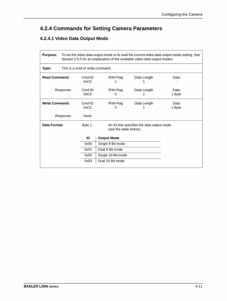
Configuring the Camera
BASLER L100k Series 4-11
DRAFT4.2.4 Commands for Setting Camera Parameters
4.2.4.1 Video Data Output Mode
Purpose: To set the video data output mode or to read the current video data output mode setting. SeeSection 2.5.5 for an explanation of the available video data output modes.
Type: This is a read or write command.
Read Command: Cmd-ID R/W-Flag Data Length Data0xC0 1 1 -
Response: Cmd-ID R/W-Flag Data Length Data0xC0 0 1 1 Byte
Write Command: Cmd-ID R/W-Flag Data Length Data0xC0 0 1 1 Byte
Response: None
Data Format: Byte 1 An ID that specifies the data output mode(see the table below).
ID Output Mode0x00 Single 8 Bit mode
0x01 Dual 8 Bit mode
0x02 Single 10 Bit mode
0x03 Dual 10 Bit mode

Configuring the Camera
4-12 BASLER L100k Series
DRAFT4.2.4.2 Exposure Time Control Mode
Purpose: To set the exposure time control mode or to read the current exposure time control modesetting. See Section 3.2 for an explanation of exposure time control modes.
Type: This is a read or write command.
Read Command: Cmd-ID R/W-Flag Data Length Data0xA0 1 1 -
Response: Cmd-ID R/W-Flag Data Length Data0xA0 0 1 1 Byte
Write Command: Cmd-ID R/W-Flag Data Length Data0xA0 0 1 1 Byte
Response: None
Data Format: Byte 1 An ID that specifies the exposure mode(see the table below).
ID Exposure Time Control Mode0x00 Free-run, Programmable
0x02 Free-run, Edge-controlled
0x04 ExSync, Level-controlled
0x05 ExSync, Programmable
0x06 ExSync, Edge-controlled
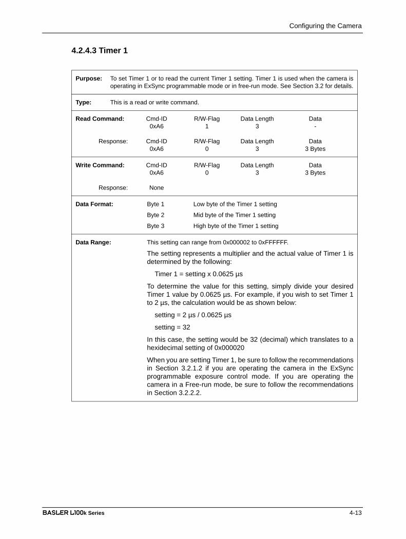
Configuring the Camera
BASLER L100k Series 4-13
DRAFT4.2.4.3 Timer 1
Purpose: To set Timer 1 or to read the current Timer 1 setting. Timer 1 is used when the camera isoperating in ExSync programmable mode or in free-run mode. See Section 3.2 for details.
Type: This is a read or write command.
Read Command: Cmd-ID R/W-Flag Data Length Data0xA6 1 3 -
Response: Cmd-ID R/W-Flag Data Length Data0xA6 0 3 3 Bytes
Write Command: Cmd-ID R/W-Flag Data Length Data0xA6 0 3 3 Bytes
Response: None
Data Format: Byte 1 Low byte of the Timer 1 setting
Byte 2 Mid byte of the Timer 1 setting
Byte 3 High byte of the Timer 1 setting
Data Range: This setting can range from 0x000002 to 0xFFFFFF.
The setting represents a multiplier and the actual value of Timer 1 isdetermined by the following:
Timer 1 = setting x 0.0625 µs
To determine the value for this setting, simply divide your desiredTimer 1 value by 0.0625 µs. For example, if you wish to set Timer 1to 2 µs, the calculation would be as shown below:
setting = 2 µs / 0.0625 µs
setting = 32
In this case, the setting would be 32 (decimal) which translates to ahexidecimal setting of 0x000020
When you are setting Timer 1, be sure to follow the recommendationsin Section 3.2.1.2 if you are operating the camera in the ExSyncprogrammable exposure control mode. If you are operating thecamera in a Free-run mode, be sure to follow the recommendationsin Section 3.2.2.2.

Configuring the Camera
4-14 BASLER L100k Series
DRAFT4.2.4.4 Timer 2
Purpose: To set Timer 2 or read the current Timer 2 setting. Timer 2 is used when the camera isoperating in free-run mode. See Section 3.2 for details.
Type: This is a read or write command.
Read Command: Cmd-ID R/W-Flag Data Length Data0xA7 1 3 -
Response: Cmd-ID R/W-Flag Data Length Data0xA7 0 3 3 Bytes
Write Command: Cmd-ID R/W-Flag Data Length Data0xA7 0 3 3 Bytes
Response: None
Data Format: Byte 1 Low byte of the Timer 2 setting
Byte 2 Mid byte of the Timer 2 setting
Byte 3 High byte of the Timer 2 setting
Data Range: This setting can range from 0x000002 to 0xFFFFFF.
The setting represents a multiplier and the actual value of Timer 2 isdetermined by the following:
Timer 2 = setting x 0.0625 µs
To determine the value for this setting, simply divide your desiredTimer 2 value by 0.0625 µs. For example, if you wish to set Timer 2to 4 µs, the calculation would be as shown below:
setting = 4 µs / 0.0625 µs
setting = 64
In this case, the setting would be 64 (decimal) which translates to ahexidecimal setting of 0x000040
When you are setting Timer 2, be sure to follow the recommendationsin Section 3.2.2.2.

Configuring the Camera
BASLER L100k Series 4-15
DRAFT4.2.4.5 Digital Shift
Purpose: To enable or disable digital shift. See Section 3.7 for an explanation of digital shift.
Type: This is a read or write command.
Read Command: Cmd-ID R/W-Flag Data Length Data0xA5 1 1 -
Response: Cmd-ID R/W-Flag Data Length Data0xA5 0 1 1 Byte
Write Command: Cmd-ID R/W-Flag Data Length Data0xA5 0 1 1 Byte
Response: None
Data Format: Byte 1 An ID that specifies the digital shift status(see the table below).
ID Digital Shift0x00 No digital shift
0x01 Digital shift once (multiplies output 2X)
0x02 Digital shift twice (multiplies output 4X)
0x03 Digital shift by three (multiplies output 8X)
See Section 3.7.3 for precautions that you must consider when using digital shift.

Configuring the Camera
4-16 BASLER L100k Series
DRAFT4.2.4.6 Area of Interest Starting Pixel
Purpose: To set the starting pixel for the Area of Interest or to read the current starting pixel setting.See Section 3.8 for details.
Type: This is a read or write command.
Read Command: Cmd-ID R/W-Flag Data Length Data0xA9 1 2 -
Response: Cmd-ID R/W-Flag Data Length Data0xA9 0 2 2 Bytes
Write Command: Cmd-ID R/W-Flag Data Length Data0xA9 0 2 2 Bytes
Response: None
Data Format: Byte 1 Low byte of the starting pixel setting
Byte 2 High byte of the starting pixel setting
Data Range: 1K sensors: 0 (0x0000) to 1023 (0x03FF)2K sensors: 0 (0x0000) to 2047 (0x07FF)(When using binary commands, the starting pixel = n +1 where n is thesetting made using this binary command. For example, if you wish to definepixel 100 as starting pixel, set 99 with the help of this command.)

Configuring the Camera
BASLER L100k Series 4-17
DRAFT4.2.4.7 Area of Interest Length in Pixels
Purpose: To set the length in pixels for the Area of Interest or to read the current length setting. SeeSection 3.8 for details.
Type: This is a read or write command.
Read Command: Cmd-ID R/W-Flag Data Length Data0xAB 1 2 -
Response: Cmd-ID R/W-Flag Data Length Data0xAB 0 2 2 Bytes
Write Command: Cmd-ID R/W-Flag Data Length Data0xAB 0 2 2 Bytes
Response: None
Data Format: Byte 1 Low byte of the length in pixel setting
Byte 2 High byte of the length in pixel setting
Data Range: 1K sensors: 1 (0x0001) to 1024 (0x0400)2K sensors: 1 (0x0001) to 2048 (0x0800)

Configuring the Camera
4-18 BASLER L100k Series
DRAFT4.2.4.8 Shading Correction
Purpose: To enable or disable shading correction or the shading correction test image mode. SeeSection 3.6 for more information on shading correction.
Type: This is a read or write command.
Read Command: Cmd-ID R/W-Flag Data Length Data0xC5 1 1 -
Response: Cmd-ID R/W-Flag Data Length Data0xC5 0 1 1 Byte
Write Command: Cmd-ID R/W-Flag Data Length Data0xC5 0 1 1 Byte
Response: None
Data Format: Byte 1 An ID that specifies the data output mode(see the table below).
ID Output Mode0x00 Shading correction off
0x01 Output shading correction data as a test image
0x02 Shading correction on
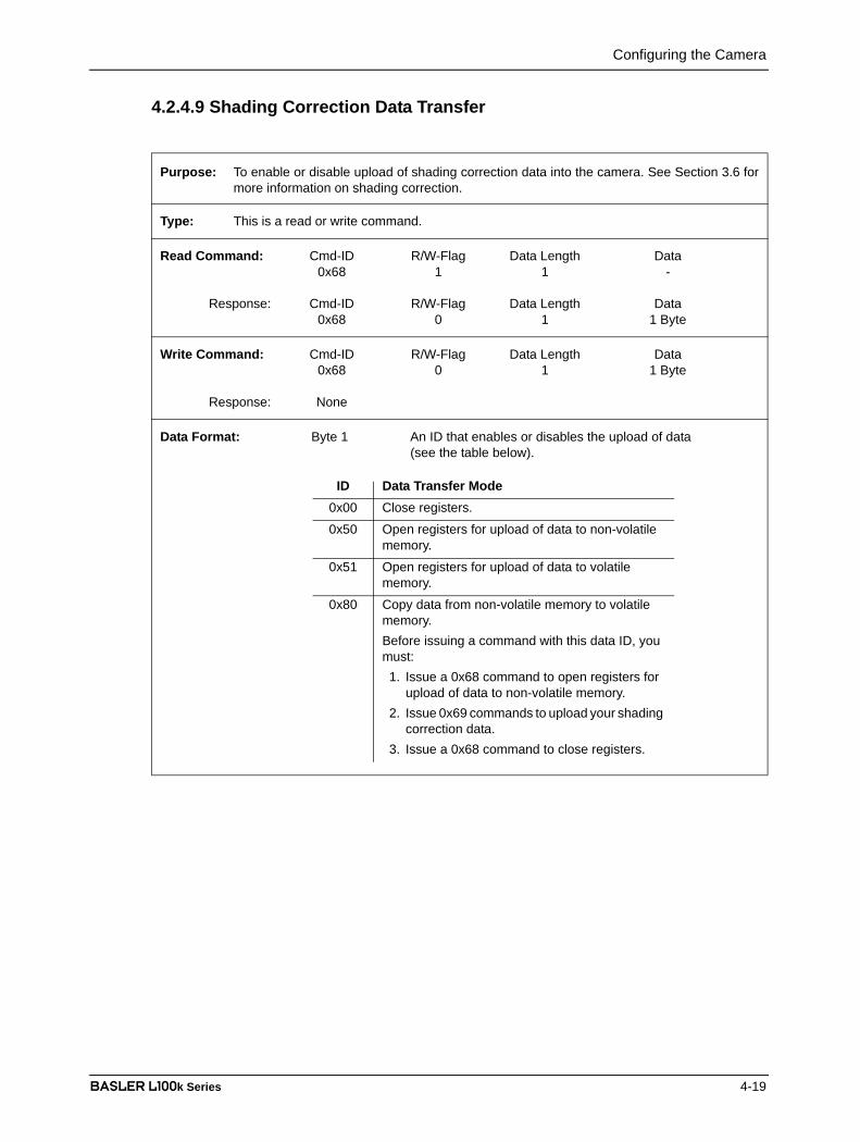
Configuring the Camera
BASLER L100k Series 4-19
DRAFT4.2.4.9 Shading Correction Data Transfer
Purpose: To enable or disable upload of shading correction data into the camera. See Section 3.6 formore information on shading correction.
Type: This is a read or write command.
Read Command: Cmd-ID R/W-Flag Data Length Data0x68 1 1 -
Response: Cmd-ID R/W-Flag Data Length Data0x68 0 1 1 Byte
Write Command: Cmd-ID R/W-Flag Data Length Data0x68 0 1 1 Byte
Response: None
Data Format: Byte 1 An ID that enables or disables the upload of data(see the table below).
ID Data Transfer Mode0x00 Close registers.
0x50 Open registers for upload of data to non-volatile memory.
0x51 Open registers for upload of data to volatile memory.
0x80 Copy data from non-volatile memory to volatile memory. Before issuing a command with this data ID, you must:1. Issue a 0x68 command to open registers for
upload of data to non-volatile memory.2. Issue 0x69 commands to upload your shading
correction data.3. Issue a 0x68 command to close registers.
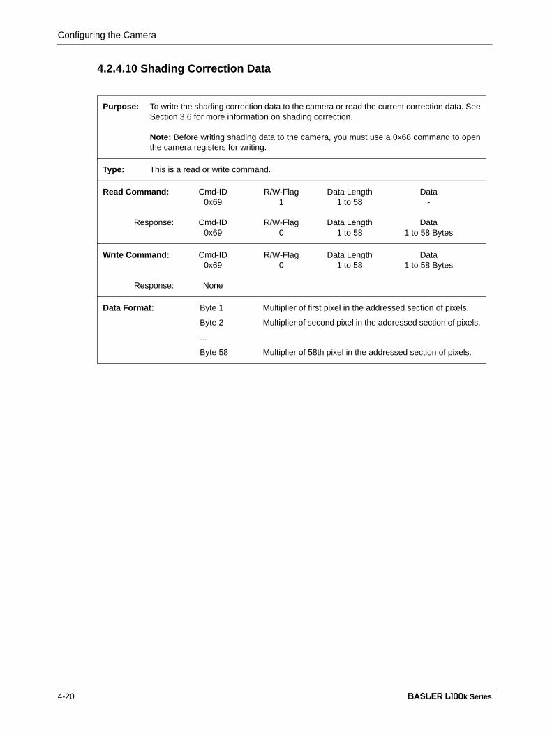
Configuring the Camera
4-20 BASLER L100k Series
DRAFT4.2.4.10 Shading Correction Data
Purpose: To write the shading correction data to the camera or read the current correction data. SeeSection 3.6 for more information on shading correction.
Note: Before writing shading data to the camera, you must use a 0x68 command to openthe camera registers for writing.
Type: This is a read or write command.
Read Command: Cmd-ID R/W-Flag Data Length Data0x69 1 1 to 58 -
Response: Cmd-ID R/W-Flag Data Length Data0x69 0 1 to 58 1 to 58 Bytes
Write Command: Cmd-ID R/W-Flag Data Length Data0x69 0 1 to 58 1 to 58 Bytes
Response: None
Data Format: Byte 1 Multiplier of first pixel in the addressed section of pixels.
Byte 2 Multiplier of second pixel in the addressed section of pixels.
...
Byte 58 Multiplier of 58th pixel in the addressed section of pixels.

Configuring the Camera
BASLER L100k Series 4-21
DRAFT4.2.4.11 Odd Pixel Gain
4.2.4.12 Odd Pixel Offset
Purpose: To set the gain for the odd pixels or to read the current odd pixel gain setting. See Section3.5 for more information on gain.
Type: This is a read or write command.
Read Command: Cmd-ID R/W-Flag Data Length Data0x80 1 2 -
Response: Cmd-ID R/W-Flag Data Length Data0x80 0 2 2 Bytes
Write Command: Cmd-ID R/W-Flag Data Length Data0x80 0 2 2 Bytes
Response: None
Data Format: Byte 1 Low byte of odd pixel gain setting
Byte 2 High byte of odd pixel gain setting
Data Range: L101k, L103k: 0 (0x0000) to 1023 (0x03FF)
L104k: 0 (0x0000) to 319 (0x013F)
Purpose: To set the offset for the odd pixels or to read the current odd pixel offset setting. See Section3.5 for more information on offset.
Type: This is a read or write command.
Read Command: Cmd-ID R/W-Flag Data Length Data0x84 1 2 -
Response: Cmd-ID R/W-Flag Data Length Data0x84 0 2 2 Bytes
Write Command: Cmd-ID R/W-Flag Data Length Data0x84 0 2 2 Bytes
Response: None
Data Format: Byte 1 Low byte of odd pixel offset setting
Byte 2 High byte of odd pixel offset setting
Data Range: L101k, L103k: 0 (0x0000) to 255 (0x00FF)
L104k: 0 (0x0000) to 1023 (0x03FF)

Configuring the Camera
4-22 BASLER L100k Series
DRAFT4.2.4.13 Even Pixel Gain
4.2.4.14 Even Pixel Offset
Purpose: To set the gain for the even pixels or to read the current even pixel gain setting. See Section3.5 for more information on gain.
Type: This is a read or write command.
Read Command: Cmd-ID R/W-Flag Data Length Data0x82 1 2 -
Response: Cmd-ID R/W-Flag Data Length Data0x82 0 2 2 Bytes
Write Command: Cmd-ID R/W-Flag Data Length Data0x82 0 2 2 Bytes
Response: None
Data Format: Byte 1 Low byte of even pixel gain setting
Byte 2 High byte of even pixel gain setting
Data Range: L101k, L103k: 0 (0x0000) to 1023 (0x03FF)
L104k: 0 (0x0000) to 319 (0x013F)
Purpose: To set the offset for the even pixels or to read the current even pixel offset setting. SeeSection 3.5 for more information on offset.
Type: This is a read or write command.
Read Command: Cmd-ID R/W-Flag Data Length Data0x86 1 2 -
Response: Cmd-ID R/W-Flag Data Length Data0x86 0 2 2 Bytes
Write Command: Cmd-ID R/W-Flag Data Length Data0x86 0 2 2 Bytes
Response: None
Data Format: Byte 1 Low byte of even pixel offset setting
Byte 2 High byte of even pixel offset setting
Data Range: L101k, L103k: 0 (0x0000) to 255 (0x00FF)
L104k: 0 (0x0000) to 1023 (0x03FF)

Configuring the Camera
BASLER L100k Series 4-23
DRAFT4.2.5 Test Image Command
4.2.6 Camera Reset Command
Purpose: To enable or disable a test image. See Section 3.9 for an explanation of the available testimages.
Type: This is a read or write command.
Read Command: Cmd-ID R/W-Flag Data Length Data0xA1 1 1 -
Response: Cmd-ID R/W-Flag Data Length Data0xA1 0 1 1 Byte
Write Command: Cmd-ID R/W-Flag Data Length Data0xA1 0 1 1 Byte
Response: None
Data Format: Byte 1 An ID that specifies the test image(see the table below).
ID Test Image0x00 No test image
0x01 Test Image 1 (gray gradient)
0x02 Test Image 2 (moving gray gradient)
Purpose: Initiates a camera reset. The behavior is similar to a power up reset.
Type: This is a write only command.
Write Command: Cmd-ID R/W-Flag Data Length Data0x42 0 2 2 Bytes
Response: None
Data Format: Byte 1 Low byte 0xCF is always used
Byte 2 High byte 0x07 is always used

Configuring the Camera
4-24 BASLER L100k Series
DRAFT4.2.7 Query Commands4.2.7.1 Read Vendor Information
4.2.7.2 Read Model Information
4.2.7.3 Read Product ID
Purpose: To read the camera vendor’s name.
Type: This is a read only command.
Read Command: Cmd-ID R/W-Flag Data Length Data0x01 1 16 -
Response: Cmd-ID R/W-Flag Data Length Data0x01 0 16 16 Bytes
Data Format: Zero terminated string if less than 16 bytes are needed for the vendorinformation. Unterminated string if all 16 bytes are needed.
Purpose: To read the camera’s model number.
Type: This is a read only command.
Read Command: Cmd-ID R/W-Flag Data Length Data0x02 1 16 -
Response: Cmd-ID R/W-Flag Data Length Data0x02 0 16 16 Bytes
Data Format: Zero terminated string if less than 16 bytes are needed for the modelinformation. Unterminated string if all 16 bytes are needed.
Purpose: To read the camera’s product ID number.
Type: This is a read only command.
Read Command: Cmd-ID R/W-Flag Data Length Data0x03 1 16 -
Response: Cmd-ID R/W-Flag Data Length Data0x03 0 16 16 Bytes
Data Format: Zero terminated string if less than 16 bytes are needed for the product IDinformation. Unterminated string if all 16 bytes are needed.

Configuring the Camera
BASLER L100k Series 4-25
DRAFT4.2.7.4 Read Serial Number
4.2.7.5 Read Camera Version
Purpose: To read the camera’s serial number.
Type: This is a read only command.
Read Command: Cmd-ID R/W-Flag Data Length Data0x04 1 16 -
Response: Cmd-ID R/W-Flag Data Length Data0x04 0 16 16 Bytes
Data Format: Zero terminated string if less than 16 bytes are needed for the serial numberinformation. Unterminated string if all 16 bytes are needed.
Purpose: To read the camera version information.
Type: This is a read only command.
Read Command: Cmd-ID R/W-Flag Data Length Data0x05 1 3 -
Response: Cmd-ID R/W-Flag Data Length Data0x05 0 3 3 Bytes
Data Format: Byte 1 Low byte of camera version BCD coded
Byte 2 High byte of camera version BCD coded
Byte 3 Protocol Version

Configuring the Camera
4-26 BASLER L100k Series
DRAFT4.2.7.6 Read Reference Gain Values
Purpose: To read the reference gain values that are determined during the camera’s factorycalibration procedure (see Section 3.5.1 on how to use the reference gain values).
Type: This is a read only command.
Read Command: Cmd-ID R/W-Flag Data Length Data0x08 1 16 -
Response: Cmd-ID R/W-Flag Data Length Data0x08 0 16 16 Bytes
Data Format: Each reference gain is stored as a 16 Bits followed by a decimal pointfollowed by 16 more Bits:
For example:
Byte Even/odd Position before/ High/Lowreference gain after decimal point byte
Byte 1 odd after low byte
Byte 2 odd after high byte
Byte 3 odd before low byte
Byte 4 odd before high byte
Byte 5 even after low byte
Byte 6 even after high byte
Byte 7 even before low byte
Byte 8 even before high byte
Bytes 9 to 16 must be ignored. These bytes are not used on the L100k.
Reference Gain High Byte b.d.p. 256 Low Byte b.d.p. High Byte a.d.p.256
------------------------------------------ Low Byte a.d.p.65536
-----------------------------------------+ + +×=b.d.p.: before decimal pointa.d.p.: after decimal point
Odd pixel reference gain Byte 4 256 Byte 3 Byte 2256
----------------- Byte 165536-----------------+ + +×=

Configuring the Camera
BASLER L100k Series 4-27
DRAFT4.2.7.7 Read Microcontroller Firmware Version
4.2.7.8 Read FPGA Firmware Version
Purpose: To read the microcontroller firmware version
Type: This is a read only command.
Read Command: Cmd-ID R/W-Flag Data Length Data0x40 1 3 -
Response: Cmd-ID R/W-Flag Data Length Data0x40 0 3 3 Bytes
Data Format: Byte 1 Low byte of firmware version BCD coded
Byte 2 High byte of firmware version BCD coded
Byte 3 Protocol Version
Purpose: To read the FPGA firmware version
Type: This is a read only command.
Read Command: Cmd-ID R/W-Flag Data Length Data0x41 1 3 -
Response: Cmd-ID R/W-Flag Data Length Data0x41 0 3 3 Bytes
Data Format: Byte 1 Low byte of firmware version BCD coded
Byte 2 High byte of firmware version BCD coded
Byte 3 undefined - 0x00 is always used

Configuring the Camera
4-28 BASLER L100k Series
DRAFT4.2.7.9 Read Camera Temperature
Purpose: To read the camera’s internal temperature. See Section 3.11 for the allowed maximumtemperature.
Type: This is a read only command.
Read Command: Cmd-ID R/W-Flag Data Length Data0x70 1 1 -
Response: Cmd-ID R/W-Flag Data Length Data0x70 0 1 1 Byte
Data Format: The temperature is given in °C as 8 bit signed number. If the MSB is 1, a temperature below 0° C is present. If the MSB is 0, the temperature is 0° C or higher.For temperatures below 0° C, a two‘s complement representation is used, that is, to obtain the actual temperature, the digital output must be inverted and1 must be added. For example:
A digital output of 11110110 would indicate a negative value because the MSB is 1
11110110 would be inverted to 00001001
00001001 translates to 9
9 + 1 = 10
The indicated temperature is therefore - 10° C
See more examples in the table below.
Temp. Digital Output- 20° C 11101100
- 10° C 1111 0110
0° C 0000 0000
+ 10° C 0000 1010
+ 25° C 0001 1001
+ 50° C 0011 0010
+ 100° C 0110 0100
Configuring the Camera
BASLER L100k Series 4-29
DRAFT4.2.8 Commands for Manipulating Configuration Sets
4.2.8.1 Copy the Factory Set or the User Set into the Work Set
Purpose: To copy the Factory Set or one of the 15 User Sets into the Work Set. See Section 3.10 foran explanation of configuration sets.
The write command will cause the selected set to be copied into the Work Set and the setwill become active immediately.
The read command returns the ID of the set that was last copied into the Work Set. (If nothinghas been copied to the Work Set since the last power up or reset, the read command willreturn the ID for “no active set.” This condition indicates that no valid Factory Set or User Setswere found. It will also cause the yellow LED on the back of the camera to show six pulses.)
Type: This is a read or write command.
Read Command: Cmd-ID R/W-Flag Data Length Data0x45 1 1 -
Response: Cmd-ID R/W-Flag Data Length Data0x45 0 1 1 Byte
Write Command: Cmd-ID R/W-Flag Data Length Data0x45 0 1 1 Byte
Response: None
Data Format: Byte 1 An ID that specifies the set.(see the table below).
Set ID Set0x00 Factory Set
0x01 User Set 1
0x02 User Set 2
0x03 User Set 3
0x04 User Set 4
0x05 User Set 5
0x06 User Set 6
0x07 User Set 7
0x08 User Set 8
0x09 User Set 9
0x0A User Set 10
0x0B User Set 11
0x0C User Set 12
0x0D User Set 13
0x0E User Set 14
0x0F User Set 15
Configuring the Camera
4-30 BASLER L100k Series
DRAFT4.2.8.2 Copy the Work Set into a User Set
Purpose: To copy the Work Set into one of the 15 User Sets. See Section 3.10 for an explanation ofconfiguration sets.
Type: This is a write only command.
Write Command: Cmd-ID R/W-Flag Data Length Data0x46 0 1 1 Byte
Response: None
Data Format: Byte 1 An ID that specifies the user set.(see the table below).
Set ID Set0x01 User Set 1
0x02 User Set 2
0x03 User Set 3
0x04 User Set 4
0x05 User Set 5
0x06 User Set 6
0x07 User Set 7
0x08 User Set 8
0x09 User Set 9
0x0A User Set 10
0x0B User Set 11
0x0C User Set 12
0x0D User Set 13
0x0E User Set 14
0x0F User Set 15

Configuring the Camera
BASLER L100k Series 4-31
DRAFT4.2.8.3 Select the Startup Pointer
Purpose: The Startup Pointer is used to tag the configuration set that will be copied into the Work Setat power on (see Section 3.10).
The write command is used to set the Startup Pointer to the Factory Set or to one of the UserSets.
The read command returns the Set ID for the current setting.
Type: This is a read or write command.
Read Command: Cmd-ID R/W-Flag Data Length Data0x47 1 1 -
Response: Cmd-ID R/W-Flag Data Length Data0x47 0 1 1 Byte
Write Command: Cmd-ID R/W-Flag Data Length Data0x47 0 1 1 Byte
Response: None
Data Format: Byte 1 An ID that specifies the set.(see the table below).
Set ID Set0x00 Factory Set
0x01 User Set 1
0x02 User Set 2
0x03 User Set 3
0x04 User Set 4
0x05 User Set 5
0x06 User Set 6
0x07 User Set 7
0x08 User Set 8
0x09 User Set 9
0x0A User Set 10
0x0B User Set 11
0x0C User Set 12
0x0D User Set 13
0x0E User Set 14
0x0F User Set 15
Configuring the Camera
4-32 BASLER L100k Series
DRAFT4.2.9 Camera Status Command
Purpose: The camera has been programmed to detect several error conditions. When an errorcondition is detected, a flag is set. The status command allows you to read the error flags.
Type: This is a read only command.
Read Command: Cmd-ID R/W-Flag Data Length Data0x43 1 2 -
Response: Cmd-ID R/W-Flag Data Length Data0x43 0 2 2 Bytes
Data Format: Byte 1 Each bit specifies an error condition (see table below).If a bit is set to 1, the error condition assigned to that bitis present. If the bit is set to 0, the error is not present.
Byte 2 Each bit specifies an error condition (see table below).If a bit is set to 1, the error condition assigned to that bit is present. If the bit is set to 0, the error is not present.
Byte 1Bit 0 No ExSync signal in the last 5 seconds
Bit 1 A reset has occurred.
Bit 2 The camera is unlocked.
Bit 3 Reserved
Bit 4 Unknown command ID specified in a read or write command
Bit 5 A read or write command could not be executed; access denied
Bit 6 The length member of the last command does not matchthe defined length
Bit 7 Parameter error(currently has no meaning - reserved for future use)
Byte 2Bit 0 FPGA; general error
Bit 1 FPGA; no FPGA firmware available
Bit 2 No FPGA/ADC command list available
Bit 3 Error in FPGA/ADC command list item
Bit 4 User set is erroneous
Bit 5 Factory set is erroneous
Bit 6 EEPROM checksum error (this is a checksum used todetermine if the contents of the EEPROM are valid)
Bit 7 No EEPROM command list available

Configuring the Camera
BASLER L100k Series 4-33
DRAFT4.2.10 Bitrate Command
Purpose: To set the bitrate of the serial communications link. The bitrate is changed immediately afterthe successful receipt of this command. (The default bitrate is 9600.)
Type: This is a write only command.
Write Command: Cmd-ID R/W-Flag Data Length Data0x44 0 4 4 Bytes
Response: None
Data Format: Byte 1 An ID that specifies the bitrate (see table below).
Byte 2 undefined - always write 0x00
Byte 3 undefined - always write 0x00
Byte 4 undefined - always write 0x00
ID Bitrate0x12 4800
0x13 9600
0x14 14400
0x15 19200
0x17 38400
0x19 57600
0x1A 76800
0x1B 115200
When changing the bitrate for serial communication, use the following procedure:
1. Issue the write command with the new bitrate.
2. Wait one second.
3. Change the bitrate on the serial port that the camera is connected to.
4. Resume communication.
Note: At a camera reset or a power off/on, the camera will return to the 9600 bpsdefault setting.
The RS-644 serial port on some Camera Link frame grabbers will only support abitrate of 9600 bps. If you are using a Camera Link frame grabber, check the grab-ber’s documentation before attempting to change the bitrate.

Configuring the Camera
4-34 BASLER L100k Series
DRAFT

Mechanical Considerations
BASLER L100k Series 5-1
DRAFT
5 Mechanical Considerations
5.1 Camera Dimensions and Mounting FacilitiesThe L100k camera housing is manufactured with high precision. Planar, parallel, and angular sidesguarantee precise mounting with high repeatability.
L100k series cameras are equipped with four M4 mounting holes on the front and two M4 mountingholes on each side as indicated in Figure 5-1.
Caution!
To avoid collecting dust on the sensor, mount a lens on the camera immediatelyafter unpacking it.

Mechanical Considerations
5-2 BASLER L100k Series
DRAFT
Figure 5-1: L100k Mechanical Dimensions (in mm)
Drawings are not to scale.

Mechanical Considerations
BASLER L100k Series 5-3
DRAFT5.2 C-Mount Adapter Dimensions
Figure 5-2: C-Mount Adapter Dimensions (in mm)
5.3 F-Mount Adapter Dimensions
Figure 5-3: F-Mount Adapter Dimensions (in mm)
Not to scale.
Not to scale.
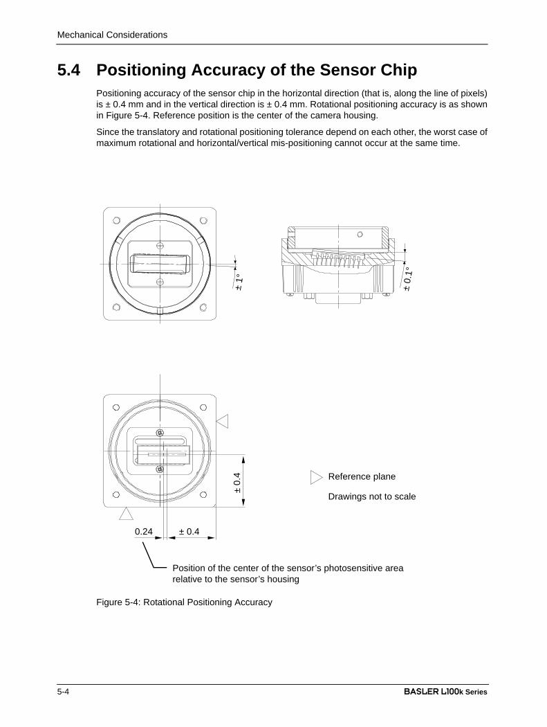
Mechanical Considerations
5-4 BASLER L100k Series
DRAFT5.4 Positioning Accuracy of the Sensor Chip
Positioning accuracy of the sensor chip in the horizontal direction (that is, along the line of pixels)is ± 0.4 mm and in the vertical direction is ± 0.4 mm. Rotational positioning accuracy is as shownin Figure 5-4. Reference position is the center of the camera housing.
Since the translatory and rotational positioning tolerance depend on each other, the worst case ofmaximum rotational and horizontal/vertical mis-positioning cannot occur at the same time.
Figure 5-4: Rotational Positioning Accuracy
Reference plane
Drawings not to scale
± 0.
1°
± 1°
± 0.40.24
± 0.
4
Position of the center of the sensor’s photosensitive arearelative to the sensor’s housing
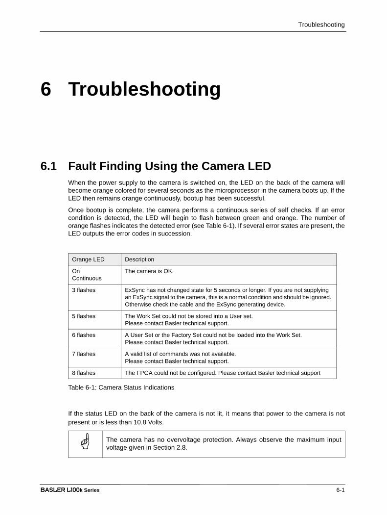
Troubleshooting
BASLER L100k Series 6-1
DRAFT
6 Troubleshooting
6.1 Fault Finding Using the Camera LEDWhen the power supply to the camera is switched on, the LED on the back of the camera willbecome orange colored for several seconds as the microprocessor in the camera boots up. If theLED then remains orange continuously, bootup has been successful.
Once bootup is complete, the camera performs a continuous series of self checks. If an errorcondition is detected, the LED will begin to flash between green and orange. The number oforange flashes indicates the detected error (see Table 6-1). If several error states are present, theLED outputs the error codes in succession.
If the status LED on the back of the camera is not lit, it means that power to the camera is notpresent or is less than 10.8 Volts.
Orange LED Description
OnContinuous
The camera is OK.
3 flashes ExSync has not changed state for 5 seconds or longer. If you are not supplying an ExSync signal to the camera, this is a normal condition and should be ignored. Otherwise check the cable and the ExSync generating device.
5 flashes The Work Set could not be stored into a User set. Please contact Basler technical support.
6 flashes A User Set or the Factory Set could not be loaded into the Work Set. Please contact Basler technical support.
7 flashes A valid list of commands was not available.Please contact Basler technical support.
8 flashes The FPGA could not be configured. Please contact Basler technical support
Table 6-1: Camera Status Indications
The camera has no overvoltage protection. Always observe the maximum inputvoltage given in Section 2.8.
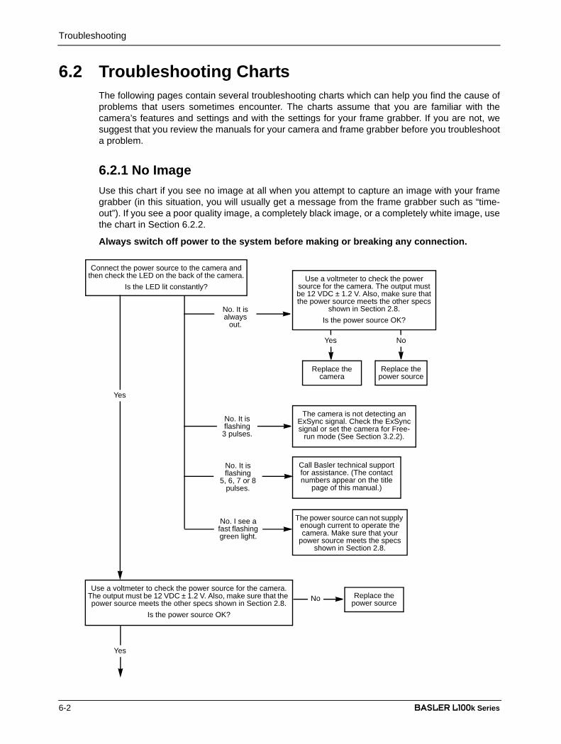
Troubleshooting
6-2 BASLER L100k Series
DRAFT6.2 Troubleshooting Charts
The following pages contain several troubleshooting charts which can help you find the cause ofproblems that users sometimes encounter. The charts assume that you are familiar with thecamera’s features and settings and with the settings for your frame grabber. If you are not, wesuggest that you review the manuals for your camera and frame grabber before you troubleshoota problem.
6.2.1 No ImageUse this chart if you see no image at all when you attempt to capture an image with your framegrabber (in this situation, you will usually get a message from the frame grabber such as “time-out”). If you see a poor quality image, a completely black image, or a completely white image, usethe chart in Section 6.2.2.
Always switch off power to the system before making or breaking any connection.
Replace the power source
Yes
Connect the power source to the camera and then check the LED on the back of the camera.
Is the LED lit constantly?Use a voltmeter to check the power
source for the camera. The output must be 12 VDC ± 1.2 V. Also, make sure that the power source meets the other specs
shown in Section 2.8.Is the power source OK?
The camera is not detecting an ExSync signal. Check the ExSync signal or set the camera for Free-
run mode (See Section 3.2.2).
Call Basler technical support for assistance. (The contact numbers appear on the title
page of this manual.)
No. It isflashing
3 pulses.
No. It isflashing
5, 6, 7 or 8pulses.
Replace the camera
No. It is always
out.
Yes
The power source can not supply enough current to operate the camera. Make sure that your
power source meets the specs shown in Section 2.8.
No. I see a fast flashing green light.
Replace the power source
Yes
Use a voltmeter to check the power source for the camera. The output must be 12 VDC ± 1.2 V. Also, make sure that the power source meets the other specs shown in Section 2.8.
Is the power source OK?
No
No
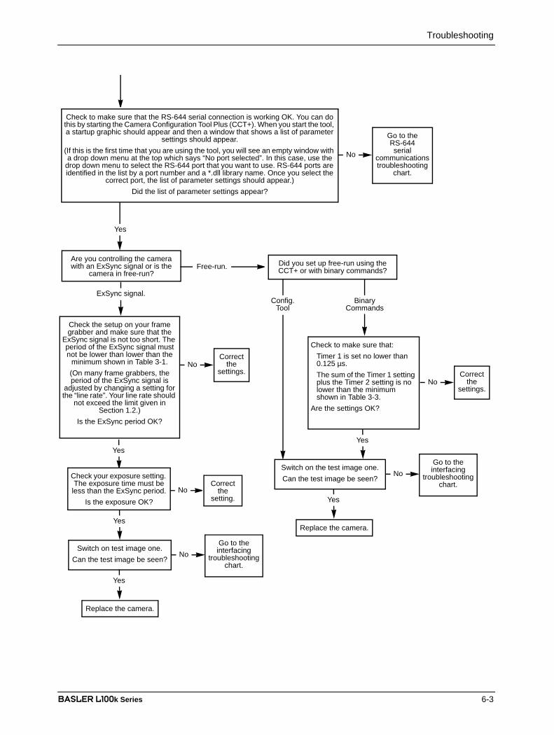
Troubleshooting
BASLER L100k Series 6-3
DRAFT
Check the setup on your frame grabber and make sure that the
ExSync signal is not too short. The period of the ExSync signal must not be lower than lower than the
minimum shown in Table 3-1.(On many frame grabbers, the period of the ExSync signal is
adjusted by changing a setting for the “line rate”. Your line rate should
not exceed the limit given in Section 1.2.)
Is the ExSync period OK?
Yes
NoCorrect
the settings.
Check your exposure setting. The exposure time must be less than the ExSync period.
Is the exposure OK?
Switch on test image one.Can the test image be seen?
Correct the
setting.
Go to the interfacing
troubleshooting chart.
Replace the camera.
No
No
Yes
Are you controlling the camera with an ExSync signal or is the
camera in free-run?
ExSync signal.
Free-run.
Config.Tool
Check to make sure that:Timer 1 is set no lower than 0.125 µs.The sum of the Timer 1 setting plus the Timer 2 setting is no lower than the minimum shown in Table 3-3.
Are the settings OK?
NoCorrect
the settings.
Binary Commands
Did you set up free-run using the CCT+ or with binary commands?
Yes
Yes
Switch on the test image one.Can the test image be seen?
Go to the interfacing
troubleshooting chart.
Replace the camera.
No
Yes
Check to make sure that the RS-644 serial connection is working OK. You can do this by starting the Camera Configuration Tool Plus (CCT+). When you start the tool, a startup graphic should appear and then a window that shows a list of parameter
settings should appear. (If this is the first time that you are using the tool, you will see an empty window with a drop down menu at the top which says “No port selected”. In this case, use the
drop down menu to select the RS-644 port that you want to use. RS-644 ports are identified in the list by a port number and a *.dll library name. Once you select the
correct port, the list of parameter settings should appear.)Did the list of parameter settings appear?
Go to theRS-644serial
communications troubleshooting
chart.
No
Yes

Troubleshooting
6-4 BASLER L100k Series
DRAFT6.2.2 Poor Quality ImageUse this chart if the image is poor quality, is completely white, or is completely black. If you get noimage at all when you attempt to capture an image with the frame grabber, use the chart thatappears in Section 6.2.1.
Contact Basler technical support. The contact numbers appear on the title page of this manual.Before you call for support, be sure to make note of the camera settings and the frame grabber settings you are
using. You should also have a captured live image and a captured test image available. Basler technical support will frequently request that you e-mail copies of these captured images.
Exit this chart.
Go to the interfacing troubleshooting chart.
Yes
Yes
No
Yes
Use the CCT+ to copy the Factory Set to the Work Set. Take the camera out of test image mode and capture a
normal image. Is the problem still present?
One of the camera’s settings was significantly misadjusted. Review the camera manual to make sure that you
are setting the camera correctly.No
Images are too bright or too dark.
Images look noisy. Other image problems.
Do the following:Make sure that the lens cap has been removed.Check the lens aperture. If the images are too dark, try opening the aperture. Try closing the aperture if they are too bright.Check the exposure time. If the images are too dark, try increasing the exposure. Try decreasing the exposure if they are too bright.Check your light source. If the images are too dark, try increasing your light intensity. Try decreasing the intensity if they are too bright.Check your gain setting. If the images are too dark, try increasing the gain. Try decreasing the gain if they are too bright.
Has the problem been corrected?
Do the following:Make sure that you are using a DC light source. Using an AC light source can make images appear noisy.Make sure that the camera has proper ventilation. If the camera becomes extremely hot, it may produce noisy images.Check the exposure time. If you use an extremely long exposure time, the images can become noisy.Check your gain setting. Using a very low or a very high gain setting can cause noisy images.Examine the objects that you are imaging. Objects with characteristics such as changing surface texture or reflectance will produce images that appear noisy.
Has the problem been corrected?
No
Exit this chart.
Yes No
Use the Camera Configuration Tool Plus (CCT+) to set the camera for test image one. Use your frame grabber to capture an image and examine the image carefully. (Most frame
grabbers include software tools that allow you to see the individual values of each pixel in the image and histograms that display distributions of the pixel values in the image.)
The pixel values in your captured test image should be exactly as described in Section 3.9. Also, if you capture several test images, the pixel values should be the same in
all of the captured test images. Are the test images OK?

Troubleshooting
BASLER L100k Series 6-5
DRAFT6.2.3 InterfacingUse the interfacing troubleshooting charts if you think that there is a problem with the cablesbetween your devices or if you have been directed here from another chart.
Interfacing Chart Always switch off power to the system before making or breaking any connection.
Reseat the cable connections at the camera and the frame grabber. After you reseated the connections, is the problem still present?
Replace the power source
Yes
No
If extra hardware is available, try to locate the problem by substitution. (Substitute only one piece of hardware at a time and
retry the system after each substitution.)After you finished making substitutions, is the problem still present?
Exit this chart.
If you have not already do so, use a voltmeter to check the power source for the camera. The output must be 12 VDC ± 1.2 V. Also, make sure that the power source meets the other specs shown in Section 2.8.
Is the power source OK?
No
Yes
No Exit this chart.
Yes
Yes
No Exit this chart.
No Exit this chart.
Contact Basler technical support. The contact numbers appear on the title page of this manual. Before you call for support, be sure to make note of the camera settings and the frame grabber settings you are using. You should also have a captured live image and a captured test image available. Basler
technical support will frequently request that you e-mail copies of these captured images.
Yes
Check the DCF (configuration) file that you are using with your frame grabber. Make sure that it is the correct file for the Basler L100k model. Be aware that sometimes different DCF
files must be used depending on which of the camera’s features you have enabled.DCF files for many types of frame grabbers are available at the Basler web site:
www.basler-vc.com. These files have all been tested with the L100k and we suggest that you use them if one is available for your type of frame grabber.
After you checked the DCF file, is the problem still present?
Check all of the cables in the system:Check Section 2.2 of this manual and make sure that you are using a cable that has the right characteristics and is not too long. It is extremely important to use the proper cables when you are working with Camera Link based cameras. Use an ohm meter to check each wire to see of it is broken or shorted to any of the other wires in the cable.
After you checked the cables, is the problem still present?
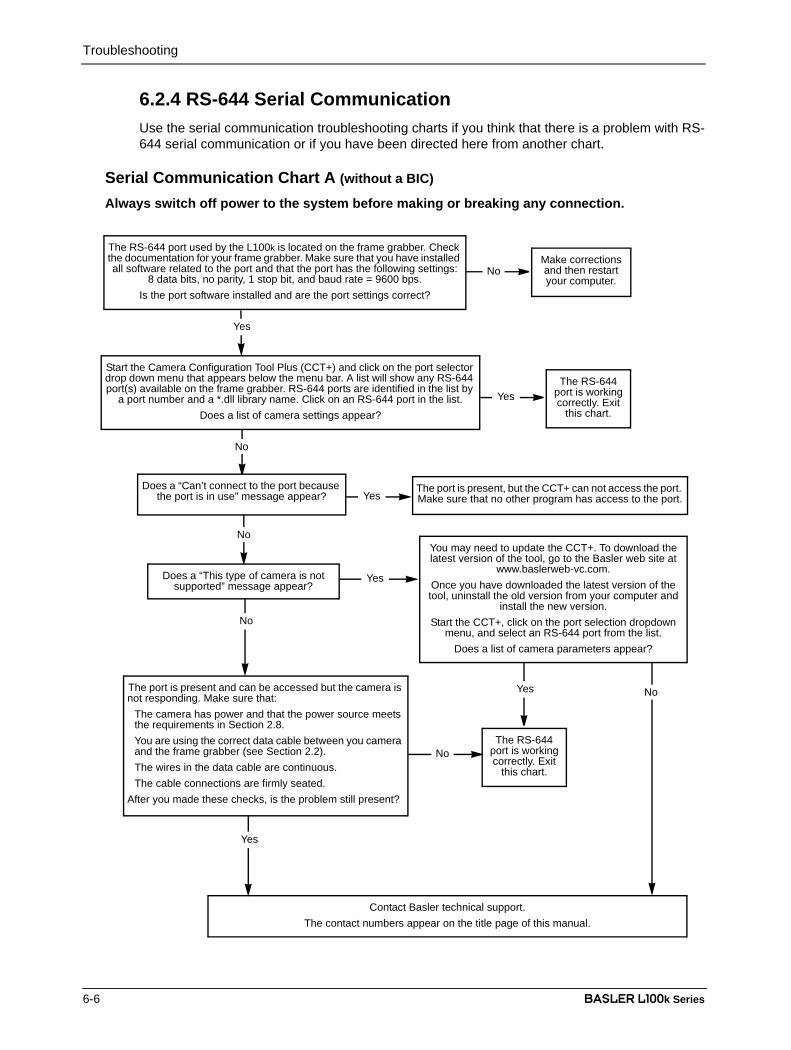
Troubleshooting
6-6 BASLER L100k Series
DRAFT6.2.4 RS-644 Serial CommunicationUse the serial communication troubleshooting charts if you think that there is a problem with RS-644 serial communication or if you have been directed here from another chart.
The RS-644 port used by the L100k is located on the frame grabber. Check the documentation for your frame grabber. Make sure that you have installed all software related to the port and that the port has the following settings:
8 data bits, no parity, 1 stop bit, and baud rate = 9600 bps.Is the port software installed and are the port settings correct?
Yes
Make corrections and then restart your computer.
No
Serial Communication Chart A (without a BIC)
Always switch off power to the system before making or breaking any connection.
Contact Basler technical support.The contact numbers appear on the title page of this manual.
Start the Camera Configuration Tool Plus (CCT+) and click on the port selector drop down menu that appears below the menu bar. A list will show any RS-644 port(s) available on the frame grabber. RS-644 ports are identified in the list by
a port number and a *.dll library name. Click on an RS-644 port in the list. Does a list of camera settings appear?
The RS-644 port is working correctly. Exit
this chart.Yes
Yes
No
Yes
No
No
Does a “Can’t connect to the port because the port is in use” message appear?
The port is present, but the CCT+ can not access the port. Make sure that no other program has access to the port.
Yes
NoThe RS-644
port is working correctly. Exit
this chart.
YesThe port is present and can be accessed but the camera is not responding. Make sure that:
The camera has power and that the power source meets the requirements in Section 2.8.You are using the correct data cable between you camera and the frame grabber (see Section 2.2).The wires in the data cable are continuous.The cable connections are firmly seated.
After you made these checks, is the problem still present?
No
Does a “This type of camera is not supported” message appear?
You may need to update the CCT+. To download the latest version of the tool, go to the Basler web site at
www.baslerweb-vc.com.Once you have downloaded the latest version of the tool, uninstall the old version from your computer and
install the new version.Start the CCT+, click on the port selection dropdown
menu, and select an RS-644 port from the list.Does a list of camera parameters appear?

Troubleshooting
BASLER L100k Series 6-7
DRAFT6.3 Before Calling Basler Technical Support
To help you as quickly and efficiently as possible when you have a problem with a Basler camera,it is important that you collect several pieces of information before you contact technical support.
Copy the form that appears on this and the next page (or download it from the support section ofwww.basler-vc.com), fill it out, and fax the pages to your local dealer or to your nearest Baslersupport center. Or, you can write an e-mail listing the requested pieces of information and with therequested files attached. Our technical support contact numbers are shown in the front section ofthis manual.
1 The camera’s product ID:
2 The camera’s serial number:
3 The operating system:
4 Frame grabber that you use with the camera:
5 CCT+ version that you use with the camera:
6 Describe the problem in as much detail as possible:
(If you need more space, use an extra sheet of paper.)
7 If known, what’s the cause of the problem?
8 When did the problem occur? After start. While running.
After a certain action (e.g., a change of parameters):

Troubleshooting
6-8 BASLER L100k Series
DRAFT
9 How often did/does the prob-lem occur?
Once. Every time.
Regularly when:
Occasionally when:
10 How severe is the problem? Camera can still be used.
Camera can be used after I take this action:
Camera can no longer be used.
11 Did your application ever run without problems?
Yes No
12 Parameter set
It is very important for Basler technical support to get a copy of the exact camera parameters that you were using when the problem occurred.
To make a copy of the parameters, open the parameter set in the CCT+ and save or dump the settings to a file. Send the generated file to Basler technical support.
If you cannot access the camera, please try to state the following parameter settings:
Video data output mode:
Exposure time control mode:
Exposure time:
Gain:
Offset:
13 Live image/test image
If you are having an image problem, try to generate and save live images that show the prob-lem. Also generate and save test images. Please save the images in BMP format, zip them, and send them to Basler technical support.

Revision History
BASLER L100k Series i
DRAFTRevision History
Doc. ID Number Date Changes
DA0005090a 5-October-2001 First draft of release covering series production cameras.
DA00050901 23-October-2001 Initial release covering series production cameras.
DA00050902 14-October-2002 Corrected the connector information in Section 1.2.Updated the Camera Link cable information in Section 2.2.1.Added more details to the Shading Correction description in Sect. 3.6.3.Added a description of the Camera Temperature feature (Sect. 3.11).Revised the troubleshooting chart in Sect. 6.2.1.
DA00050903 20-March-2003 Revised the stated maximum line rates in Section 1.2.
Updated the pixel timing charts in Section 2.5.5 and the timing numbers in Sections 3.2.1.2 and 3.2.2.2 to reflect revisions made to the sensor timing by the manufacturer.
Made revisions throughout to include instructions for using the Camera Configuration Tool Plus (CCT+).
DA00050904 29-June-2007 Updated Singapore and U.S. addresses.
Increased weight of the camera with C-mount adapter to 220 g in Section 1.2.
Added environmental requirements for storage in Section 1.3.
Added warning against overvoltage in Section 1.4.
Added warnings not to reverse polarity of input power in Sections 1.4 and 2.8.
Corrected type of power connector in Section 2.1.3.
Modified Figure 2-3 in Section 2.3.
Removed step 4 and added to note box in Section 4.2.10.
Corrected “Data“, “Byte 1“, and “Byte 2“ in Section 4.2.6.
Added Section 6.3.
Added feedback section.
DA00050905 8-April-2008 Added a warning to Section 1.4 advising users not to remove the serial number label.
Corrected the connector part number in Section 2.1.3.
Corrected vertical and rotational positioning accuracy in Section 5.4.
Added drawing in Figure 5-4 in Section 5.4 showing the relative posi-tions of sensor housing and photosensitive area.

Revision History
ii BASLER L100k Series
DRAFT

Feedback
BASLER L100k Series iii
DRAFTFeedback
Your feedback will help us improve our documentation. Please click the link below to access an onlinefeedback form. Your input is greatly appreciated.
http://www.baslerweb.com/umfrage/survey.html

Feedback
iv BASLER L100k Series
DRAFT

Index
BASLER L100k Series v
DRAFTIndex
Aarea of interest
explained.........................................3-29setting with binary commands.........4-16
BBIC ........................................................2-18binary command frame ...........................4-6binary commands
error checking ...................................4-8examples...........................................4-9explained...........................................4-5read command ..................................4-8timeouts ............................................4-8write command..................................4-8
bitratesetting with binary commands.........4-33
block check charactercalculating .......................................4-10defined ..............................................4-6
Ccable length.............................................2-4cable specifications
camera link........................................2-4power ................................................2-4
cable type................................................2-4camera configuration tool
auto refresh.......................................4-3closing the tool ..................................4-2opening the tool ................................4-2parameter description window ..........4-3refresh button....................................4-3selecting a port..................................4-3
camera link implementation information..2-4camera version
reading with binary commands .......4-25cleaning the camera and sensor .............1-4C-mount adapter .....................................5-3configuration sets
explained.........................................3-33manipulating with binary commands.............................................. 4-29, 4-30
configuration toolsee camera configuration tool
configuring the camerawith binary commands ......................4-5with the config tool ............................4-2
connector types.......................................2-3
Ddata output mode
see video data output mode(s)digital shift
explained.........................................3-24setting with binary commands.........4-15
dimensionscamera ..............................................5-1C-mount adapter ...............................5-3F-mount adapter ...............................5-3
Eedge-controlled exposure mode
explained................................... 3-3, 3-6setting with binary commands.........4-12
environmental requirementscamera ..............................................1-3
exposure timerelation to exp.time control modes.................................................. 3-3–3-7
exposure time control mode(s)explained................................... 3-3–3-7setting with binary commands.........4-12
ExSync signal..........................................2-6explained...........................................3-3rules ..................................................3-5
Ffactory set
copying to the work set ...................4-29explained.........................................3-33
fill factor...................................................1-2F-mount adapter......................................5-3FPGA firmware version
reading with binary commands .......4-27

Index
vi BASLER L100k Series
DRAFTfree-run
explained...........................................3-6rules ..................................................3-8setting with binary commands.........4-12
functional descriptioncamera ..............................................3-1
Ggain
explained.........................................3-10setting with binary commands.............................................. 4-21, 4-22
Hhumidity requirements
camera ..............................................1-3
Iinput signals ............................................2-6
to the camera ....................................2-6integrate enabled .......................... 2-16, 3-9interfacing the camera.............................2-1
Kk-BIC .....................................................2-18
LLED .........................................................6-1
on the camera .................................2-18level-controlled exposure mode
explained...........................................3-3setting with binary commands.........4-12
line rate ...................................................1-2
Mmicrocontroller firmware version
reading with binary commands .......4-27model number, camera
reading with binary commands .......4-24model tab ................................................4-4mounting facilities....................................5-1
Ooffset
explained.........................................3-10setting with binary commands.............................................. 4-21, 4-22
output modesee video data output mode(s)
output signalsfrom the camera................................2-7
Pphoto response non-uniformity................1-2pin assignments
camera ..............................................2-2pin numbering .........................................2-3pixel clock
on the camera ...................................2-7pixel size .................................................1-2positioning accuracy of the sensor chip ..5-4power requirements
camera .................................... 1-2, 2-18precautions
camera ..............................................1-4programmable exposure mode
explained................................... 3-4, 3-7setting with binary commands.........4-12
Rread command
error checking ...................................4-8example ............................................4-9
resetting the camera with binary commands..............................................................4-23responsivity .............................................1-3RS-644
output ..............................................2-18serial connection .............................2-17
Ssensor type..............................................1-2serial connection
see RS-644 serial connectionserial number, camera
label ..................................................1-4viewing with binary commands .......4-25

Index
BASLER L100k Series vii
DRAFTshading correction
creating a shading table..................3-17enabling data transfer .....................4-19explained.........................................3-17setting with binary commands.........4-18writing correction data.....................4-20
specificationscamera ..............................................1-2
startup pointerexplained.........................................3-33setting with binary commands.........4-31
statuschecking with binary commands .....4-32explained.........................................3-34
Ttemperature
checking with binary commands .....4-28explained.........................................3-34
temperature requirementscamera ..............................................1-3
test imageexplained.........................................3-31setting with binary commands.........4-23
timer 1explained................................... 3-4, 3-6setting with binary commands.........4-13
timer 2explained...........................................3-6setting with binary commands.........4-14
troubleshooting........................................6-1troubleshooting chart
interfacing .........................................6-5no image ...........................................6-2poor quality image.............................6-4RS-644 serial communication ...........6-6
Uuser sets
copying to the work set ...................4-29explained.........................................3-33
Vventilation
camera ..............................................1-3video data output mode(s)
explained................................. 2-9–2-14setting with binary commands.........4-11
Wweight
camera ..............................................1-2work set
copying to a user set.......................4-30explained.........................................3-33relationship to the config tool ............4-3
write commanderror checking ...................................4-8example ............................................4-9