(Kubota 4F Diesel) (SN/ 008015-- ) Sweeper...
84
800 *9012844* Sweeper Operator Manual 9012844 Rev. 01 (03-2015) (Kubota 4F Diesel) (SN/ 008015-- ) TennantTruet Parts and Supplies North America / International For the latest parts manuals and other language Operator manuals, visit: www.tennantco.com/manuals
Transcript of (Kubota 4F Diesel) (SN/ 008015-- ) Sweeper...

800
*9012844*
SweeperOperator Manual
9012844Rev. 01 (03-2015)
(Kubota 4F Diesel)(SN/ 008015-- )
TennantTruet Parts and Supplies
North America / InternationalFor the latest parts manuals and otherlanguage Operator manuals, visit:
www.tennantco.com/manuals

INTRODUCTION
This manual is furnished with each new model. It provides necessary operation and maintenance instructions.
Read this manual completely and understandthe machine before operating or servicing it.
This machine will provide excellent service. However, the best results will be obtained at minimum costs if:
S The machine is operated with reasonable care.
S The machine is maintained regularly - per the machine maintenance instructions provided.
S The machine is maintained with manufacturer supplied or equivalent parts.
PROTECT THE ENVIRONMENTPlease dispose of packaging materials,used machine components such asbatteries and fluids in anenvironmentally safe way according tolocal waste disposal regulations.
Always remember to recycle.
Model No. --
Serial No. --
Installation Date --
Please fill out at time of installation for futurereference.
MACHINE DATA
INTENDED USE
The 800 is an industrial rider machine designed to sweep hard surfaces (concrete, asphalt, stone, synthetic, etc).Typical applications include industrial warehouses, manufacturing facilities, distribution facilities, stadiums, arenas,convention centers, parking facilities, transportation terminals, and construction sites. Do not use this machine on soil,grass, artificial turf, or carpeted surfaces. This machine can be used both indoors and outdoors, but ensure there isadequate ventilation if used indoors. Do not use this machine other than described in this Operator Manual.
Tennant CompanyPO Box 1452Minneapolis, MN 55440Phone: (800) 553--8033 or (763) 513--2850www.tennantco.com
CALIFORNIA PROPOSITION 65 WARNING:Engine exhaust from this product contains chemicals known to the State of California to cause cancer,birth defects, or other reproductive harm.
II Speed and Thermo Sentry are United States registered trademarks of the Tennant Company.
Specifications and parts are subject to change without notice.
Original instructions, Copyright E 2014, 2015 TENNANT Company, Printed in U.S.A.

CONTENTS
1800 4F Diesel 9012844 (3−2014)
CONTENTS
PageSafety Precautions 3. . . . . . . . . . . . . . . . . . . . . . .Operation 7. . . . . . . . . . . . . . . . . . . . . . . . . . . . . . .
Machine Components 7. . . . . . . . . . . . . . . . . .Controls And Instruments 8. . . . . . . . . . . . . . .Symbol Definitions 9. . . . . . . . . . . . . . . . . . . . .Operation Of Controls 11. . . . . . . . . . . . . . . . . .
Directional Pedal 11. . . . . . . . . . . . . . . . . . .Brake Pedal 11. . . . . . . . . . . . . . . . . . . . . . .Parking Brake Pedal 11. . . . . . . . . . . . . . . .Steering Wheel Tilt Handle 12. . . . . . . . . . .Main Brush Adjustment Knob 12. . . . . . . . .Side Brush Adjustment Knob 12. . . . . . . . .Horn Button 12. . . . . . . . . . . . . . . . . . . . . . . .Charging System Light 13. . . . . . . . . . . . . .Engine Oil Pressure Light 13. . . . . . . . . . . .Engine Water Temperature Light 13. . . . . .Hopper Temperature Light −
Thermo−Sentry 13. . . . . . . . . . . . . . . . . .Main Brush Shut Down Light 14. . . . . . . . .Clogged Dust Filter Light 14. . . . . . . . . . . .Hopper Door Light (Option) 14. . . . . . . . . .Check Engine Light 14. . . . . . . . . . . . . . . . .Clogged Hydraulic Filter Light 15. . . . . . . .Fuel Level Gauge 15. . . . . . . . . . . . . . . . . . .Hour Meter 15. . . . . . . . . . . . . . . . . . . . . . . .Operating Lights Switch 15. . . . . . . . . . . . .Hazard Light Switch (Option) 16. . . . . . . . .Filter Shaker Switch 16. . . . . . . . . . . . . . . . .Vacuum Fan Switch 16. . . . . . . . . . . . . . . . .EDM (Engine Display Module) 17. . . . . . . .Adjusting The Engine Speed (RPM) 17. . .Parking Brake Indicator 17. . . . . . . . . . . . . .Glow Plug Indicator 17. . . . . . . . . . . . . . . . .Operator Seat 18. . . . . . . . . . . . . . . . . . . . . .Seat Belts (Option) 18. . . . . . . . . . . . . . . . .Seat Support 18. . . . . . . . . . . . . . . . . . . . . . .Windshield Wiper Switch (Option) 19. . . . .Dome Light Switch (Option) 19. . . . . . . . . .Heater Knob (Option) 19. . . . . . . . . . . . . . .Fan Speed Switch (Option) 19. . . . . . . . . .Air Conditioning Switch (Option) 20. . . . . .Air Control Vents (Option) 20. . . . . . . . . . . .
Brush Information 21. . . . . . . . . . . . . . . . . . . . .How The Machine Works 21. . . . . . . . . . . . . . .Pre−Operation Checklist 22. . . . . . . . . . . . . . . .Starting The Machine 23. . . . . . . . . . . . . . . . . .Turning Off The Machine 24. . . . . . . . . . . . . . .While Operating The Machine 25. . . . . . . . . . .Sweeping 26. . . . . . . . . . . . . . . . . . . . . . . . . . . .Stop Sweeping 27. . . . . . . . . . . . . . . . . . . . . . . .Emptying The Hopper 28. . . . . . . . . . . . . . . . . .Engaging Hopper Support Bar 30. . . . . . . . . . .Disengaging Hopper Support Bar 31. . . . . . . .Options 32. . . . . . . . . . . . . . . . . . . . . . . . . . . . . .
Vacuum Wand 32. . . . . . . . . . . . . . . . . . . . .Regenerative Filter System (RFS) 35. . . .
Machine Troubleshooting 36. . . . . . . . . . . . . . .
PageMaintenance 37. . . . . . . . . . . . . . . . . . . . . . . . . . . . .
Maintenance Chart 37. . . . . . . . . . . . . . . . . . . .Lubrication 41. . . . . . . . . . . . . . . . . . . . . . . . . . .
Rear Wheel Support 41. . . . . . . . . . . . . . . .Front Wheel Bearings 41. . . . . . . . . . . . . . .Side Brush Pivot Pins 41. . . . . . . . . . . . . . .Main Brush Adjustment 41. . . . . . . . . . . . . .
Hydraulics 42. . . . . . . . . . . . . . . . . . . . . . . . . .Hydraulic Fluid Reservoir 42. . . . . . . . . . . .Hydraulic Fluid 43. . . . . . . . . . . . . . . . . . . . .Hydraulic Hoses 43. . . . . . . . . . . . . . . . . . . .
Engine 44. . . . . . . . . . . . . . . . . . . . . . . . . . . . . . .Engine Oil 44. . . . . . . . . . . . . . . . . . . . . . . . .Cooling System 44. . . . . . . . . . . . . . . . . . . .Engine Belt 45. . . . . . . . . . . . . . . . . . . . . . . .Air Conditioning Belt (Option) 45. . . . . . . . .Draining Water From The Water /
Fuel Separator 46. . . . . . . . . . . . . . . . . .Fuel Lines 46. . . . . . . . . . . . . . . . . . . . . . . . .Priming The Fuel System 46. . . . . . . . . . . .Fuel Filters 47. . . . . . . . . . . . . . . . . . . . . . . .Oil Separator Element 47. . . . . . . . . . . . . . .PCV (Positive Crankcase Ventilation)
Valve 47. . . . . . . . . . . . . . . . . . . . . . . . . .EGR (Exhaust Gas Recirculation)
Cooler 48. . . . . . . . . . . . . . . . . . . . . . . . . .DPF (Diesel Particulate Filter) 48. . . . . . . .Exhaust Manifold 48. . . . . . . . . . . . . . . . . . .Turbo Charger 49. . . . . . . . . . . . . . . . . . . . .Valve Clearance 49. . . . . . . . . . . . . . . . . . . .Air Intake Hoses 49. . . . . . . . . . . . . . . . . . . .Air Filter Indicator 50. . . . . . . . . . . . . . . . . . .Air Filter Assembly 50. . . . . . . . . . . . . . . . . .DPF (Diesel Particulate Filter)
Regeneration 51. . . . . . . . . . . . . . . . . . . .DPF (Diesel Particulate Filter) Alerts 52. .DPF (Diesel Particulate Filter)
Status Icons 54. . . . . . . . . . . . . . . . . . . .Initiating A Sweeping Regeneration 54. . .Initiating A Parked Regeneration 55. . . . . .
Battery 58. . . . . . . . . . . . . . . . . . . . . . . . . . . . . . .Circuit Breakers 58. . . . . . . . . . . . . . . . . . . . . . .Debris Hopper 59. . . . . . . . . . . . . . . . . . . . . . . .
Removing Or Replacing The Hopper Dust Filter 59. . . . . . . . . . . . . . . . . . . . . .
Cleaning The Hopper Dust Filter 60. . . . . .Thermo Sentry 60. . . . . . . . . . . . . . . . . . . . .
Main Brush 61. . . . . . . . . . . . . . . . . . . . . . . . . .Replacing Or Rotating The Main Brush 61Checking / Adjusting The Main
Brush Pattern 62. . . . . . . . . . . . . . . . . . .Adjusting The Main Brush Width 63. . . . . .Adjusting The Main Brush Taper 63. . . . . .
Side Brush(es) 64. . . . . . . . . . . . . . . . . . . . . . . .Replacing The Side Brush 64. . . . . . . . . . .Adjusting The Side Brush Pattern 64. . . . .

CONTENTS
800 4F Diesel 9012844 (3−2014)2
PageSkirts And Seals 65. . . . . . . . . . . . . . . . . . . . . . .
Hopper Lip Skirts 65. . . . . . . . . . . . . . . . . . .Hopper Side Skirt 65. . . . . . . . . . . . . . . . . . .Brush Compartment Skirts 65. . . . . . . . . . .Rear Skirts 65. . . . . . . . . . . . . . . . . . . . . . . .Brush Door Seals 66. . . . . . . . . . . . . . . . . . .Hopper Dust Seal 66. . . . . . . . . . . . . . . . . . .Hopper Seals 66. . . . . . . . . . . . . . . . . . . . . .Hopper Door Seals 66. . . . . . . . . . . . . . . . .Hopper Vacuum Fan Seal 67. . . . . . . . . . . .Hopper Cover Seal 67. . . . . . . . . . . . . . . . .
Brakes And Tires 68. . . . . . . . . . . . . . . . . . . . . .Service Brakes 68. . . . . . . . . . . . . . . . . . . . .Parking Brake 68. . . . . . . . . . . . . . . . . . . . . .Tires 68. . . . . . . . . . . . . . . . . . . . . . . . . . . . . .Front / Rear Wheels 68. . . . . . . . . . . . . . . .
Propelling Motor 69. . . . . . . . . . . . . . . . . . . . . . .Air Conditioner Filter (Option) 69. . . . . . . . . . .Pushing, Towing, And Transporting
The Machine 70. . . . . . . . . . . . . . . . . . . . . . .Pushing Or Towing The Machine 70. . . . . .Transporting The Machine 71. . . . . . . . . . .
Machine Jacking 73. . . . . . . . . . . . . . . . . . . . . .Storage Information 73. . . . . . . . . . . . . . . . . . . .
Specifications 74. . . . . . . . . . . . . . . . . . . . . . . . . . . .General Machine Performance 75. . . . . . . . . .Power Type 75. . . . . . . . . . . . . . . . . . . . . . . . . .Steering 75. . . . . . . . . . . . . . . . . . . . . . . . . . . . . .Hydraulic System 75. . . . . . . . . . . . . . . . . . . . . .Braking System 76. . . . . . . . . . . . . . . . . . . . . . .Tires 76. . . . . . . . . . . . . . . . . . . . . . . . . . . . . . . . .Machine Dimensions 76. . . . . . . . . . . . . . . . . . .

SAFETY PRECAUTIONS
3800 4F Diesel 9012844 (3−2014)
IMPORTANT SAFETY INSTRUCTIONS − SAVE THESE INSTRUCTIONS
The following precautions are used throughoutthis manual as indicated in their description:
WARNING: To warn of hazards orunsafe practices that could result insevere personal injury or death.
FOR SAFETY: To identify actions that must befollowed for safe operation of equipment.
The following information signals potentiallydangerous conditions to the operator. Know whenthese conditions can exist. Locate all safetydevices on the machine. Report machinedamage or faulty operation immediately.
WARNING: Moving belt and fan. Keepaway.
WARNING: Machine can emit excessivenoise. Hearing loss can result. Wearhearing protection.
WARNING: Machine emits toxic gases.Serious injury or death can result.Provide adequate ventilation.
WARNING: Raised hopper may fall.Engage hopper support bar.
WARNING: Lift arm pinch point. Stayclear of hopper lift arms.
WARNING: Burn hazard. Hot surface. DoNOT touch.
This machine may be equipped withtechnology that automatically communicatesover the cellular network. If this machine willbe operated where cell phone use is restrictedbecause of concerns related to equipmentinterference, please contact a Tennantrepresentative for information on how todisable the cellular communicationfunctionality.
FOR SAFETY:
1. Do not operate machine:− Unless trained and authorized.− Unless operator manual is read and
understood.− Under the influence of alcohol or
drugs.− While using a cell phone or other
types of electronic devices.− Unless mentally and physically
capable of following machineinstructions.
− If it is not in proper operatingcondition.
− Without filters in place.− In areas where flammable
vapors/liquids or combustible dustsare present.
− In areas that are too dark to safely seethe controls or operate the machineunless operating / headlights areturned on.
− In areas with possible falling objectsunless equipped with overhead guard.
2. Before starting machine:− Check machine for fluid leaks− Keep sparks and open flame away
from refueling area.− Make sure all safety devices are in
place and operate properly.− Check brakes and steering for proper
operation.− Adjust seat and fasten seat belt (if
equipped).
3. When starting machine:− Keep foot on brake and directional
pedal in neutral.

SAFETY PRECAUTIONS
800 4F Diesel 9012844 (3−2014)4
4. When using machine:− Use only as described in this manual.− Do not pick up burning or smoking
debris, such as cigarettes, matches orhot ashes
− Go slowly on inclines and slipperysurfaces.
− Do not sweep on ramp inclines thatexceed 15% grade or transport(GVWR) on ramp inclines that exceed15% grade.
− Use brakes to stop machine.− Reduce speed when turning.− Keep all parts of body inside operator
station while machine is moving.− Use care when reversing machine.− Move machine with care when hopper
is raised.− Do not raise hopper when machine is
on an incline.− Make sure adequate clearance is
available before raising hopper.− Keep children and unauthorized
persons away from machine.− Do not carry passengers on machine.− Always follow safety and traffic rules.− Report machine damage or faulty
operation immediately.
5. Before leaving or servicing machine:− Do not park near combustible
materials, dusts, gases, or liquids.− Stop on level surface.− Set parking brake.− Turn off machine and remove key.
6. Before initiating an active parkedregeneration:− Stop on level surface in a well
ventilated open area.− Park in low traffic areas away from
pedestrians and other equipment.− Do not park near combustible
materials, dusts, gases, or liquids. Donot park indoors or in enclosed areas.
− Set parking brake.− Do not leave machine unattended.
7. When servicing machine:− All work must be done with sufficient
lighting and visibility.− Avoid moving parts. Do not wear loose
clothing, jewelry and secure long hair.− Block machine tires before jacking
machine up.− Jack machine up at designated
locations only. Support machine withjack stands.
− Use hoist or jack that will support theweight of the machine.
− Do not power spray or hose offmachine near electrical components.
− Disconnect battery connections beforeworking on machine.
− Avoid contact with battery acid.− Avoid contact with hot engine coolant.− Do not remove cap from radiator when
engine is hot.− Allow engine to cool.− Keep flames and sparks away from
fuel system service area. Keep areawell ventilated.
− Use cardboard to locate leakinghydraulic fluid under pressure.
− All repairs must be performed by atrained service mechanic.
− Do not modify the machine from itsoriginal design.
− Use Tennant supplied or approvedreplacement parts.
− Wear personal protective equipmentas needed and where recommended inthis manual.
For Safety: wear hearing protection.
For Safety: wear protective gloves.
For Safety: wear eye protection.
For Safety: wear protective dust mask.
8. When loading/unloading machineonto/off truck or trailer:− Empty debris hopper before loading
machine.− Use ramp, truck or trailer that will
support the weight of the machine andoperator.
− Do not load/unload on ramp inclinesthat exceed 27% grade.
− Use winch. Do not drive the machineonto/off the truck or trailer unless theload height is 380 mm (15 in) or lessfrom the ground.
− Turn off machine and remove key.− Set parking brake after machine is
loaded.− Block machine tires.− Tie machine down to truck or trailer.
SAFETY PRECAUTIONS
5800 4F Diesel 9012844 (3−2014)
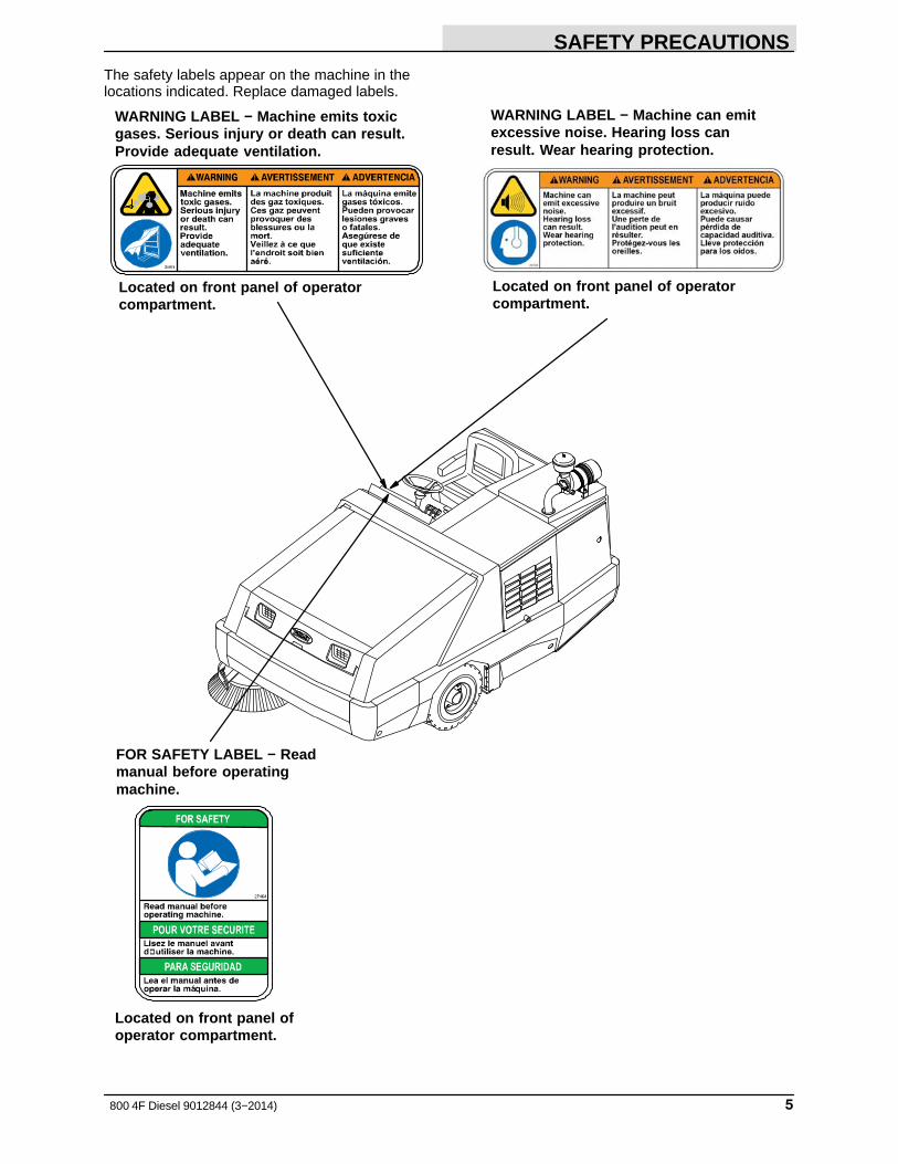
The safety labels appear on the machine in thelocations indicated. Replace damaged labels.
Located on front panel of operatorcompartment.
Located on front panel ofoperator compartment.
FOR SAFETY LABEL − Readmanual before operatingmachine.
WARNING LABEL − Machine emits toxicgases. Serious injury or death can result.Provide adequate ventilation.
WARNING LABEL − Machine can emitexcessive noise. Hearing loss canresult. Wear hearing protection.
Located on front panel of operatorcompartment.
SAFETY PRECAUTIONS
800 4F Diesel 9012844 (3−2014)6
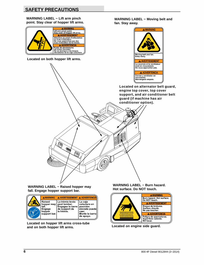
Located on hopper lift arms cross-tubeand on both hopper lift arms.
Located on both hopper lift arms.
WARNING LABEL − Raised hopper mayfall. Engage hopper support bar.
WARNING LABEL − Lift arm pinchpoint. Stay clear of hopper lift arms.
WARNING LABEL − Moving belt andfan. Stay away.
Located on engine side guard.
WARNING LABEL − Burn hazard.Hot surface. Do NOT touch.
Located on alternator belt guard,engine top cover, top coversupport, and air conditioner beltguard (if machine has airconditioner option).
OPERATION
7800 4F Diesel 9012844 (3−2014)
OPERATION
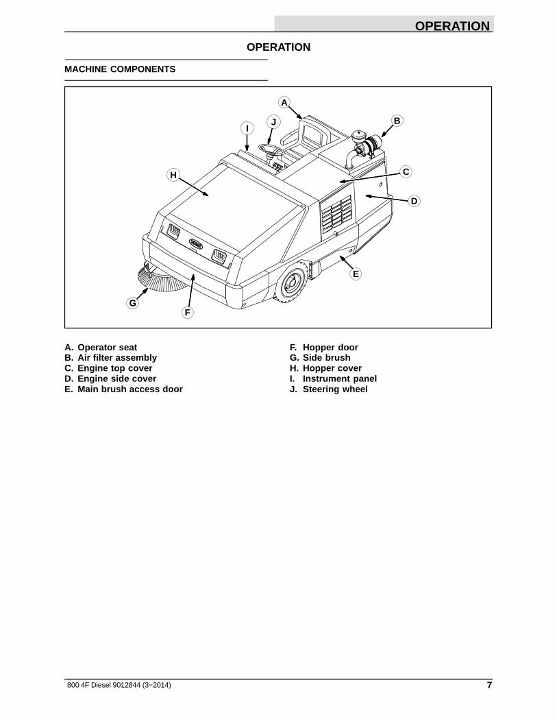
MACHINE COMPONENTS
A
BI
H C
GF
J
E
D
A. Operator seatB. Air filter assemblyC. Engine top coverD. Engine side coverE. Main brush access door
F. Hopper doorG. Side brushH. Hopper coverI. Instrument panelJ. Steering wheel

OPERATION
8 800 4F Diesel 9012844 (3−2014)
CONTROLS AND INSTRUMENTS
A
B
C
E
F G H
I
J
K
L
M
N
O
P
Q RS
TU
V
W
X
Y
Z
AA
AB
AC
D
ADAE
AF
A. Directional pedalB. Brake pedalC. Parking Brake LeverD. Side Brush SwitchE. Side Brush Down Pressure KnobF. Hopper Door Lever
G. Hopper Rollout LeverH. Hopper Lift LeverI. Horn ButtonJ. Charging System LightK. Engine Oil Pressure LightL. Engine Water Temperature LightM. Hopper Temperature Light −
Thermo SentryN. Main Brush Shut Down LightO. Clogged Dust Filter LightP. Hopper Door Light (Option)
Q. Fuel Level GaugeR. Hour MeterS. Hazard Light Switch (Option)T. Operating Light SwitchU. Filter Shaker SwitchV. Vacuum Fan Switch
W. Ignition switchX. Main Brush SwitchY. Steering WheelZ. Steering Column Tilt Lever
AA. Circuit BreakersAB. Check Engine LightAC. Side Brush Switch, Left (Option)AD. Heater Knob (Option)AE. Clogged Hydraulic Filter LightAF. EDM (Engine Display Module)
OPERATION
9800 4F Diesel 9012844 (3−2014)
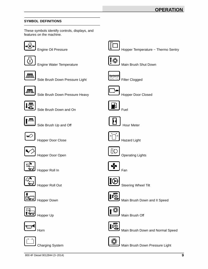
SYMBOL DEFINITIONS
These symbols identify controls, displays, andfeatures on the machine.
Engine Oil Pressure Hopper Temperature − Thermo Sentry
Engine Water Temperature Main Brush Shut Down
Side Brush Down Pressure Light Filter Clogged
Side Brush Down Pressure Heavy Hopper Door Closed
Side Brush Down and On Fuel
Side Brush Up and Off Hour Meter
Hopper Door Close Hazard Light
Hopper Door Open Operating Lights
Hopper Roll In Fan
Hopper Roll Out Steering Wheel Tilt
Hopper Down Main Brush Down and II Speed
Hopper Up Main Brush Off
Horn Main Brush Down and Normal Speed
Charging System Main Brush Down Pressure Light

OPERATION
10 800 4F Diesel 9012844 (3−2014)
Main Brush Down Pressure Heavy Circuit Breaker 7
Circuit Breaker 1 Circuit Breaker 8
Circuit Breaker 2 Circuit Breaker 9
Circuit Breaker 3 Parking Brake
Circuit Breaker 4 Hydraulic Filter Clogged
Circuit Breaker 5 Ultra Low Diesel fuel only
Circuit Breaker 6
OPERATION
11800 4F Diesel 9012844 (3−2014)
OPERATION OF CONTROLS
DIRECTIONAL PEDAL
Press the top of the Directional pedal to moveforward and the bottom of the pedal to movebackward. The pedal returns to the neutralposition when it is released.
BRAKE PEDAL
Press the Brake pedal to stop the machine.
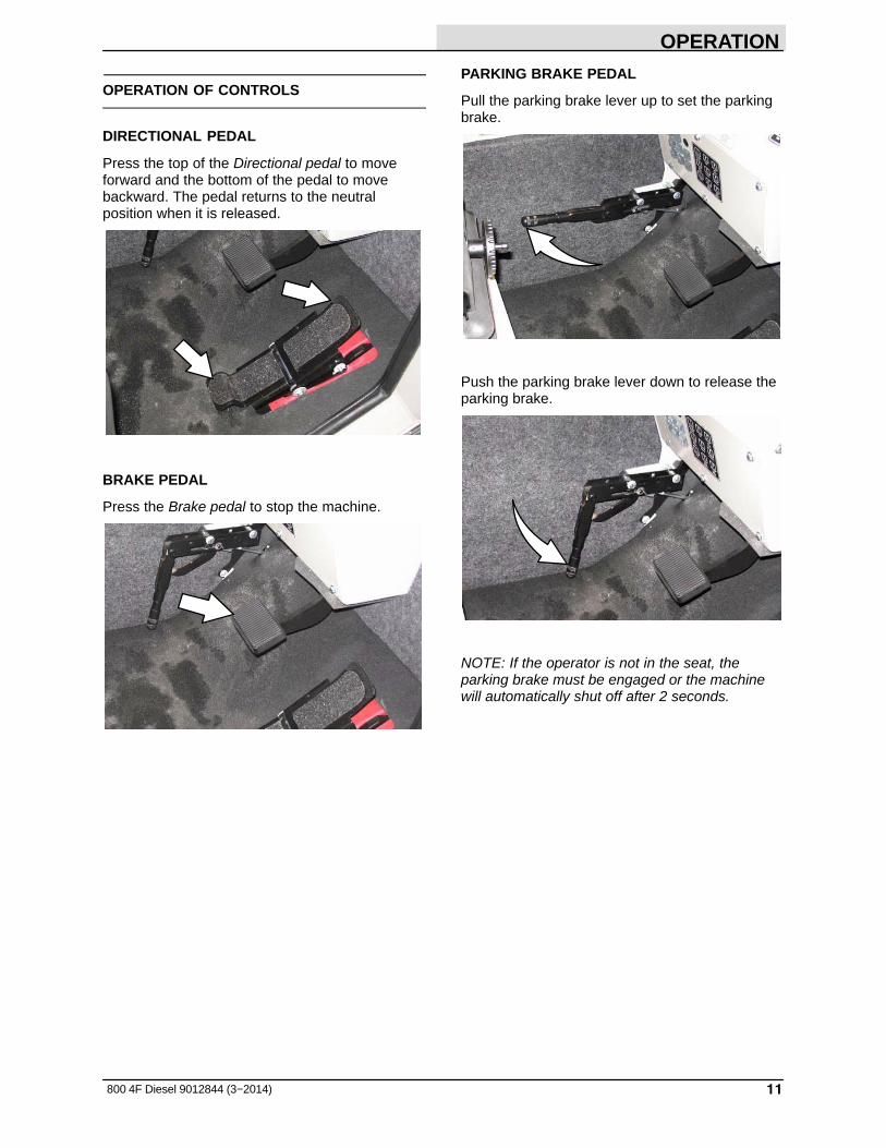
PARKING BRAKE PEDAL
Pull the parking brake lever up to set the parkingbrake.
Push the parking brake lever down to release theparking brake.
NOTE: If the operator is not in the seat, theparking brake must be engaged or the machinewill automatically shut off after 2 seconds.

OPERATION
12 800 4F Diesel 9012844 (3−2014)
STEERING WHEEL TILT HANDLE
The steering wheel tilt handle controls the angleof the steering wheel.
Adjust: Pull out the tilt handle, move the steeringwheel up or down, and release the tilt handle.
MAIN BRUSH ADJUSTMENT KNOB
The main brush adjustment knob changes theamount of contact the main brush has with thesurface being swept. Refer to ADJUSTING THEMAIN BRUSH WIDTH section of this manual.
SIDE BRUSH ADJUSTMENT KNOB
The side brush adjustment knob changes theamount of contact the side brush has with thesurface being swept. Refer to ADJUSTING THESIDE BRUSH PATTERN section of this manual.
NOTE: The side brush adjustment knob can berepositioned. Lift the knob, turn it to the desiredposition, and release it.
HORN BUTTON
The horn button operates the horn.
Sound: Press the button.

OPERATION
13800 4F Diesel 9012844 (3−2014)
CHARGING SYSTEM LIGHT
The charging system light comes on when thealternator is not operating within normal range;13.5 to 14.5 V. If the light comes on, stopoperating the machine. Contact a TENNANTservice representative.
07757
ENGINE OIL PRESSURE LIGHT
The engine oil pressure light comes on when theengine oil pressure falls below 40 kPa (5 psi). Ifthe light comes on, stop operating the machine.Contact a TENNANT service representative.
07758
ENGINE WATER TEMPERATURE LIGHT
The engine water temperature light comes onwhen the temperature of the engine coolant ismore than 113� C (235� F). If the light comes on,stop operating the machine. Contact a TENNANTservice representative.
07759
HOPPER TEMPERATURE LIGHT − THERMO−SENTRY
The hopper temperature light comes on when theThermo−Sentry senses that there is excessiveheat in the hopper, possibly from a fire. TheThermo Sentry will stop the vacuum fan.
The Thermo−Sentry has to be reset manually, seeTHERMO−SENTRY in MAINTENANCE.
07760

OPERATION
14 800 4F Diesel 9012844 (3−2014)
MAIN BRUSH SHUT DOWN LIGHT
The main brush shut down light comes on whenthere is excessive down pressure for the mainbrush, or there is a problem with the main andside brush hydraulic motor circuit. The brushpressures can be reduced with the main brushand side brush pressure knobs.
07761
CLOGGED DUST FILTER LIGHT
The clogged dust filter light comes on when thehopper dust filter is clogged.
To clean the filter, hold the vacuum and filtershaker lever in the Filter shaker position. If theclogged dust filter light remains lit, manually cleanthe hopper dust filter. See HOPPER DUSTFILTER in the MAINTENANCE section of thismanual.
NOTE: The clogged dust filter light also comeson when the hopper door is closed and thevacuum fan is on.
07762
HOPPER DOOR LIGHT (OPTION)
The hopper door light comes on when the hopperdoor is open.
Make sure the hopper door is closed and thehopper door light is off, before sweeping.
07763
CHECK ENGINE LIGHT
The check engine light comes on when there is aengine performance issue. Call a Tennant servicerepresentative if the check engine light comes onduring machine operation.
OPERATION
15800 4F Diesel 9012844 (3−2014)
CLOGGED HYDRAULIC FILTER LIGHT
The clogged hydraulic filter light comes on whenthe hydraulic filter is clogged. If this light remainson, have the hydraulic filter changed as soon aspossible.
FUEL LEVEL GAUGE
The fuel level gauge indicates how much fuel is inthe fuel tank.
IMPORTANT: Use Ultra Low Sulfur Diesel FuelOnly. DO NOT use other fuels such asBio−Diesel or add aftermarket additives to the fuelin this machine. Other fuels and aftermarketadditives will damage emission components,requiring more frequent and costlier maintenance.Engine damage due to use of other fuels andaftermarket additives may not be covered underthe machine warranty.
07764
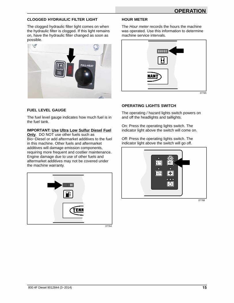
HOUR METER
The Hour meter records the hours the machinewas operated. Use this information to determinemachine service intervals.
07765
OPERATING LIGHTS SWITCH
The operating / hazard lights switch powers onand off the headlights and taillights.
On: Press the operating lights switch. Theindicator light above the switch will come on.
Off: Press the operating lights switch. Theindicator light above the switch will go off.
07768

OPERATION
16 800 4F Diesel 9012844 (3−2014)
HAZARD LIGHT SWITCH (OPTION)
The hazard light switch powers on and off thehazard light.
On: Press the hazard light switch. The indicatorlight above the switch will come on.
Off: Press the hazard light switch. The indicatorlight above the switch will go off.
07766
FILTER SHAKER SWITCH
The filter shaker switch starts the hopper dustfilter shaker. The shaker automatically operatesfor 40 seconds.
Start: Press the filter shaker switch. The indicatorlight will remain on while the filter shaker isoperating.
Stop: Press the filter shaker switch again IFwanting to stop the filter shaker during the 40 second shaking cycle.
NOTE: The vacuum fan shuts off while the filtershaker is operating.
07767
VACUUM FAN SWITCH
The vacuum fan switch starts and stops thevacuum fan.
Start: Press the vacuum fan switch. The indicatorlight above the switch will come on.
Stop: Press the vacuum fan switch. The indicatorlight above the switch will go off.
07769

OPERATION
17800 4F Diesel 9012844 (3−2014)
EDM (ENGINE DISPLAY MODULE)
The EDM displays engine RPM, engine status,and regeneration messages and alerts. Use thesoft buttons located on the bottom of the EDM toaccess the various menus for adjusting the EDMand engine settings and checking diagnostics andsystem information. Refer to the EDMmanufacturer operator manual for additionalinformation on how to use the EDM.
ADJUSTING THE ENGINE SPEED (RPM)
Use the EDM (engine display module) to adjustthe engine speed.
Idle: Press the soft button located under 1350RPM to adjust the engine to the idle speed.
Low: Press the soft button located under 2000RPM to adjust the engine to the low work speed.
High: Press the soft button located under 2400RPM to adjust the engine to the high work speed.
PARKING BRAKE INDICATOR
The parking brake indicator comes on when theparking brake is engaged. Release the parkingbrake before operating the machine.
OPERATION
18 800 4F Diesel 9012844 (3−2014)
OPERATOR SEAT
The operator seat has two adjustments. Theadjustments are for the front to rear seat positionand ride stiffness.
The front−to−back adjustment lever adjusts theseat position.
08443
The ride stiffness is adjusted with the stiffnessknob. Turn the knob clockwise to increase the ridestiffness, and counter-clockwise to decrease theride stiffness.
08444
SEAT BELTS (OPTION)
FOR SAFETY: Before starting machine, adjustseat and fasten seat belt (if equipped).
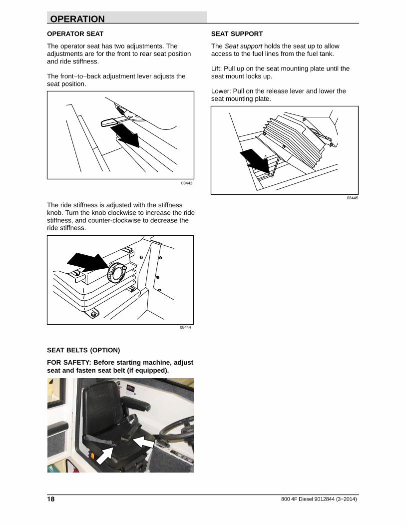
SEAT SUPPORT
The Seat support holds the seat up to allowaccess to the fuel lines from the fuel tank.
Lift: Pull up on the seat mounting plate until theseat mount locks up.
Lower: Pull on the release lever and lower theseat mounting plate.
08445
OPERATION
19800 4F Diesel 9012844 (3−2014)
WINDSHIELD WIPER SWITCH (OPTION)
The windshield wiper switch operates thewindshield wiper on the cab option.
On: Pull out on the switch.
Off: Push in on the switch.
DOME LIGHT SWITCH (OPTION)
The dome light switch controls the dome light onthe cab option.
On: Press on the switch.
Off: Press on the switch again.
HEATER KNOB (OPTION)
The heater knob controls the cab heater on thecab option. The heater knob is located above theparking brake lever.
On: Pull the knob out until the air temperature isat the desired comfort level. For maximum heat,pull the knob out all the way.
Off: Push the knob in all the way.
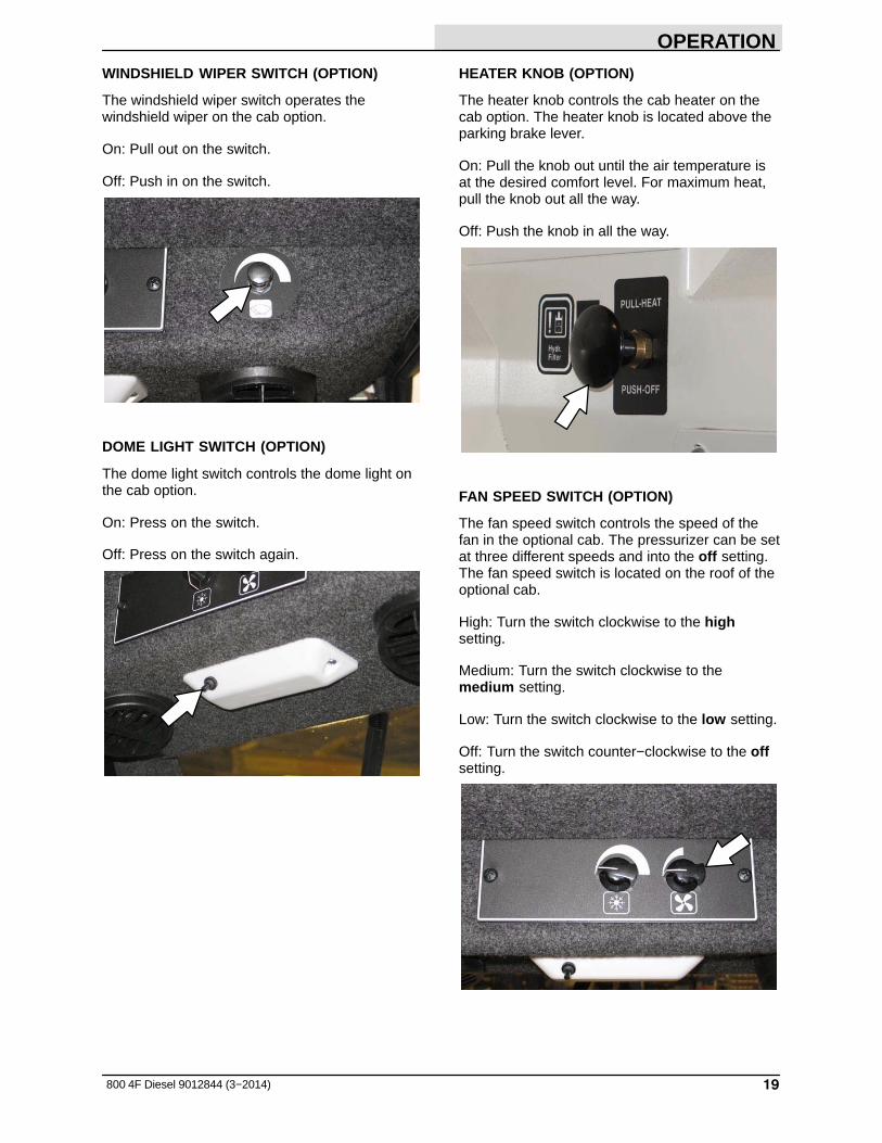
FAN SPEED SWITCH (OPTION)
The fan speed switch controls the speed of thefan in the optional cab. The pressurizer can be setat three different speeds and into the off setting.The fan speed switch is located on the roof of theoptional cab.
High: Turn the switch clockwise to the highsetting.
Medium: Turn the switch clockwise to themedium setting.
Low: Turn the switch clockwise to the low setting.
Off: Turn the switch counter−clockwise to the offsetting.

OPERATION
20 800 4F Diesel 9012844 (3−2014)
AIR CONDITIONING SWITCH (OPTION)
The air conditioning switch operates the cab’s airconditioner in the optional cab. The airconditioning switch is located on the roof of theoptional cab.
On: Turn the switch clockwise until the airtemperature is at the desired comfort level. Formaximum cooling, turn the switch clockwise allthe way to the maximum position.
Off: Turn the switch counter−clockwise all the wayto the off position.
AIR CONTROL VENTS (OPTION)
The air control vents control the direction of theair flow in an optional cab. Turn the vents untilthey meet your desired comfort level. Fordefrosting, direct the air control vents onto thewindows. This creates warm, dry air which worksbest for defrosting. If this causes the windows tofog, turn on the air conditioner for drier air.
OPERATION
21800 4F Diesel 9012844 (3−2014)
BRUSH INFORMATION
For best results, use the correct brush type for thecleaning application.
NOTE: The amount and type of soilage play animportant role in determining the type of brushesto use. Contact a Tennant representative forspecific recommendations.
Polypropylene 8-double Row Main Brush −Recommended for general sweeping applications.
Polypropylene and Wire 8-double Row MainBrush − Recommended for general sweepingand slightly impacted debris.
Crinkle Wire 8-double Row Main Brush −Recommended for foundry sweeping where heatmay melt synthetic bristles. The stiff wire bristlescut through compacted grime, hard to sweep dirt,and dirt mixed with oil, grease, or mud.
Nylon 24-row Main Brush − Recommended forsevere dust conditions on rough surfaces. Thisbrush has excellent pickup and long life.
Nylon Patrol Main Brush − Recommended forbulky debris swept at faster speeds.
Heavy Gauge Polypropylene 8-double RowMain Brush − Recommended for sweepingoutdoor areas. The stiffer bristles provideexceptional pickup of heavier bulky debris.
Polypropylene Side Brush − Recommended forgeneral sweeping of light to medium debris.
Nylon Side Brush − Recommended for generalsweeping of rough or irregular surfaces. Nylonhas a long wear life.
Flat Wire Side Brush − Recommended foroutdoor curb-side sweeping where dirt is heavy orcompacted.
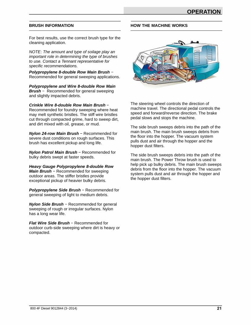
HOW THE MACHINE WORKS
The steering wheel controls the direction ofmachine travel. The directional pedal controls thespeed and forward/reverse direction. The brakepedal slows and stops the machine.
The side brush sweeps debris into the path of themain brush. The main brush sweeps debris fromthe floor into the hopper. The vacuum systempulls dust and air through the hopper and thehopper dust filters.
The side brush sweeps debris into the path of themain brush. The Power Throw brush is used tohelp pick up bulky debris. The main brush sweepsdebris from the floor into the hopper. The vacuumsystem pulls dust and air through the hopper andthe hopper dust filters.

OPERATION
22 800 4F Diesel 9012844 (3−2014)
PRE−OPERATION CHECKLIST
� Check the engine oil level.
� Check the engine coolant level.
� Check the windshield washer fluid level (whenapplicable).
� Check the radiator and hydraulic cooler finsfor debris.
� Check the hydraulic fluid level
� Check the machine for fluid leaks.
� Check the air filter indicator.
� Check the skirts and seals for damage andwear.
� Check the condition of the main brush.Remove string, banding, plastic wrap, or otherdebris wrapped around the brush.
� Side Brush Option: Check the condition of thebrush. Remove string, banding, plastic wrap,or other debris wrapped around the brush(es).
� Side Brush Option: Check the condition of theside brush skirt.
� Check for rubbing hoses or wires and leaks orobstructions.
� Check the condition of the hopper dust filterand seals. Clean as required.
� Check the brakes and steering for properoperation.
� Check the horn, headlights, taillights, safetylights, and backup alarm (if equipped).
� Check the fuel level.
� Empty the debris hopper.
� Check the service records to determinemaintenance requirements.

OPERATION
23800 4F Diesel 9012844 (3−2014)
STARTING THE MACHINE
1. Sit in the operator seat, engage the parkingbrake, and ensure the directional pedal is inneutral.
FOR SAFETY: When starting machine, keepfoot on brake and directional pedal in neutral.
2. Turn the ignition switch clockwise to the ONposition without starting the machine. The”Wait to start, preheating” message appearson the EDM screen. The preheating messagewill leave the screen when the glow plugs arefinished heating and the engine is ready tostart.
3. Turn the ignition switch key clockwise until theengine starts.
NOTE: Do not operate the starter motor for morethan 10 seconds at a time or after the engine hasstarted. Allow the starter to cool between startingattempts or damage to the starter motor mayoccur.
NOTE: The EDM (engine display module) mayalert the operator that a DPF (Diesel ParticulateFilter) regeneration is necessary. For instructionson how to initiate a DPF regeneration, see DPFREGENERATION in the MAINTENANCE sectionof this manual.
4. Allow the engine and hydraulic system towarm up three to five minutes.
WARNING: Machine emits toxic gases.Severe respiratory damage orasphyxiation can result. Provideadequate ventilation. Consult with yourregulatory authorities for exposurelimits. Keep engine properly tuned.
5. Press the EDM (engine display module) softbutton below either 2000 RPM or 2400 RPMto elevate the engine RPM to a leveladequate for cleaning.

OPERATION
24 800 4F Diesel 9012844 (3−2014)
6. Release the machine parking brake.
7. Turn on lights.
8. Drive the machine to the area to be cleaned.
TURNING OFF THE MACHINE
1. Stop sweeping.
2. Remove foot from the directional pedal. Stepon the brake pedal.
3. Press the EDM (engine display module) softbutton under 1350 RPM to lower the engine toidle.
4. Set the machine parking brake.
5. Turn the ignition switch key counterclockwiseto turn off the engine. Remove the switch key.
FOR SAFETY: Before leaving or servicingmachine, do not park near combustiblematerials, dust, gases, or liquids. Stop onlevel surface, set parking brake, turn offmachine, and remove key.
OPERATION
25800 4F Diesel 9012844 (3−2014)
WHILE OPERATING THE MACHINE
IMPORTANT: This machine is equipped with aDPF (Diesel Particulate Filter) to meet the latestemissions requirements. This filter automaticallyburns all soot collecting in the DPF when themachine is operating at full power / capacity.When the machine has not been operated at fullpower to eliminate the soot from the DPF, themachine will need to run through a Regenerationprocess. The EDM (engine display module) alertsthe operator when a regeneration process isrequired. For instructions how to initiate a DPFregeneration, see DPF REGENERATION in theMAINTENANCE section of this manual.
NOTE: Operate the machine at full power /capacity to avoid having to initiate a regeneration.See DPF REGENERATION in theMAINTENANCE section of this manual.
Pick up oversized debris before sweeping. Pickup wire, string, twine, large pieces of wood, or anyother debris that could become wrapped aroundor tangled in the brushes.
Drive as straight a path as possible. Avoidbumping into posts or scraping the sides of themachine. Overlap the sweep paths by severalcentimeters (a few inches).
Avoid turning the steering wheel too sharply whenthe machine is in motion. The machine is veryresponsive to the movement of the steering wheel.Avoid sudden turns, except in emergencies.
Adjust the machine speed and brush pressure.Use the lowest brush pressure for bestperformance.
Keep the machine moving to prevent damagingfloor finishes.
If poor cleaning performance is observed, stopcleaning and refer to MACHINETROUBLESHOOTING in this manual.
Perform the Daily Maintenance Procedures aftereach use (see MACHINE MAINTENANCE in thismanual).
Drive the machine slowly on inclines. Use thebrake pedal to control machine speed ondescending inclines. Sweep with the machine upinclines rather than down inclines.
FOR SAFETY: When using machine, go slowlyon inclines and slippery surfaces.
FOR SAFETY: When using machine, do notraise hopper when machine is on an incline.

OPERATION
26 800 4F Diesel 9012844 (3−2014)
SWEEPING
NOTE: Operate the machine at full power /capacity to avoid having to initiate a regeneration.See DPF REGENERATION in theMAINTENANCE section of this manual.
1. Ensure that the hopper is completely lowered.
2. Press the EDM (engine display module) softbutton below either 2000 RPM or 2400 RPMto elevate the engine RPM to a leveladequate for cleaning.
NOTE: Operate the machine at either 2000 RPMor 2400 RPM when sweeping. Operating at 1350RPM will reduce cleaning performance.
3. The hopper door must be closed duringsweeping. If machine is equipped with thehopper door light option, be sure the hopperdoor light is off. If the hopper door light is on,close the hopper door.
0847608476
4. Place the main brush switch in the Normal orII Speed position.
5. Push the top of the side brush switch into theOn/Down position.
6. Press the vacuum fan switch to start thevacuum.
07769
7. Sweep as needed.

OPERATION
27800 4F Diesel 9012844 (3−2014)
STOP SWEEPING
1. Push the bottom of the side brush switch intothe Off/Up position.
2. Place the main brush switch in the middle Offposition.
3. Press the filter shaker switch to shake thehopper dust filter.
07767
OPERATION
28 800 4F Diesel 9012844 (3−2014)
EMPTYING THE HOPPER
1. Stop sweeping and shake the filter.
2. Slowly drive the machine to the debris site ordebris container.
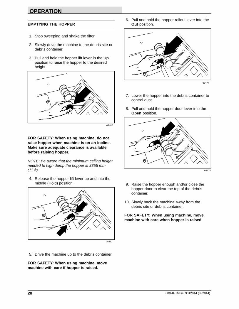
3. Pull and hold the hopper lift lever in the Upposition to raise the hopper to the desiredheight.
08480
FOR SAFETY: When using machine, do notraise hopper when machine is on an incline.Make sure adequate clearance is availablebefore raising hopper.
NOTE: Be aware that the minimum ceiling heightneeded to high dump the hopper is 3355 mm(11 ft).
4. Release the hopper lift lever up and into themiddle (Hold) position.
08481
5. Drive the machine up to the debris container.
FOR SAFETY: When using machine, movemachine with care if hopper is raised.
6. Pull and hold the hopper rollout lever into theOut position.
08477
7. Lower the hopper into the debris container tocontrol dust.
8. Pull and hold the hopper door lever into theOpen position.
08474
9. Raise the hopper enough and/or close thehopper door to clear the top of the debriscontainer.
10. Slowly back the machine away from thedebris site or debris container.
FOR SAFETY: When using machine, movemachine with care when hopper is raised.
OPERATION
29800 4F Diesel 9012844 (3−2014)
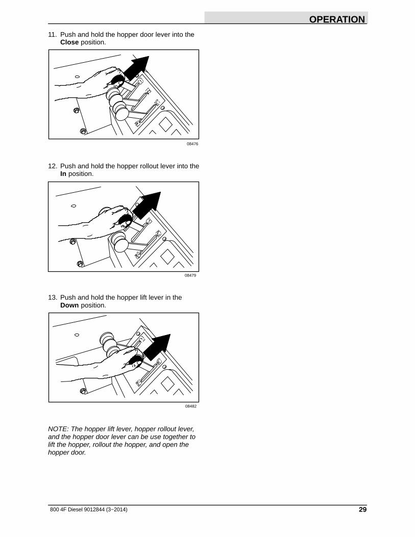
11. Push and hold the hopper door lever into theClose position.
08476
12. Push and hold the hopper rollout lever into theIn position.
08479
13. Push and hold the hopper lift lever in theDown position.
08482
NOTE: The hopper lift lever, hopper rollout lever,and the hopper door lever can be use together tolift the hopper, rollout the hopper, and open thehopper door.

OPERATION
30 800 4F Diesel 9012844 (3−2014)
ENGAGING HOPPER SUPPORT BAR
1. Set the machine parking brake.
FOR SAFETY: When starting machine, keepfoot on brake and directional pedal in neutral.
2. Start the machine.
3. Raise the hopper all the way up.
08480
FOR SAFETY: When using machine, makesure adequate clearance is available beforeraising hopper.
NOTE: Be aware that the minimum ceiling heightneeded to high dump the hopper is 2490 mm (98 in).
4. Remove the support bar from the storage clip.
08589
WARNING: Raised hopper may fall.Engage hopper support bar.
5. Lower and position the hopper support baronto the support bar stop.
6. Slowly lower the hopper so the hoppersupport bar rests on the support bar stop.
08482
WARNING: Lift arm pinch point. Stayclear of hopper lift arms.
7. Turn off the engine.
OPERATION
31800 4F Diesel 9012844 (3−2014)
DISENGAGING HOPPER SUPPORT BAR
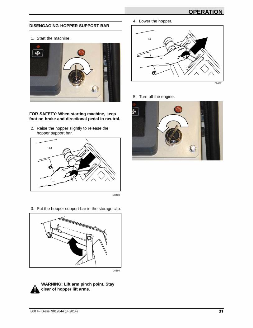
1. Start the machine.
FOR SAFETY: When starting machine, keepfoot on brake and directional pedal in neutral.
2. Raise the hopper slightly to release thehopper support bar.
08480
3. Put the hopper support bar in the storage clip.
08590
WARNING: Lift arm pinch point. Stayclear of hopper lift arms.
4. Lower the hopper.
08482
5. Turn off the engine.

OPERATION
32 800 4F Diesel 9012844 (3−2014)
OPTIONS
VACUUM WAND
The vacuum wand uses the machine vacuumsystem. The vacuum hose and wand allowpick-up of debris that is out of reach of themachine.
1. Stop the machine within reach of the area tobe vacuumed.
2. Set the machine parking brake.
NOTE: If the operator is not in the seat, theparking brake must be engaged or the machinewill automatically shut off after 2 seconds.
3. Press the vacuum fan switch to turn off thevacuum fan. The indicator light above theswitch will go off.
07769
4. Place the main brush switch into the middleOff position to turn off and lift the main brush.
5. Place the bottom of the switch(es) into theOff/Up position to turn off and lift the sidebrush(es).
6. Turn off the engine.
7. Open the forward hopper access door andengage the lift arm.

OPERATION
33800 4F Diesel 9012844 (3−2014)
8. Remove the vacuum plug from the vacuumadaptor tube in front of the hopper.
9. Remove the vacuum wand and hose from themounting clips and assemble them together.
10. Connect the vacuum hose to the vacuumadaptor tube in front of the hopper.
11. Slide the vacuum door lever down and to theleft into the locked position to close thevacuum door.
12. Start the engine.
13. Press the vacuum fan switch to turn on thevacuum. The indicator light above the switchwill go on.
07769
14. Vacuum the area as needed.
WARNING: Accident may occur. Do notoperate vacuum wand while driving.
15. When done vacuuming, press the vacuum fanswitch to turn off the vacuum fan. Theindicator light above the switch will go off.
07769

OPERATION
34 800 4F Diesel 9012844 (3−2014)
16. Slide the vacuum door lever to the right andup from the locked position to open thevacuum door.
17. Disconnect the vacuum hose from thevacuum adaptor tube in front of the hopper.
18. Disassemble the vacuum hose assembly andplace back onto the hopper in the mountingclips.
19. Reinstall the vacuum plug into the vacuumadaptor tube in front of the hopper, disengagethe lift arm, and close the forward hopperaccess door.

OPERATION
35800 4F Diesel 9012844 (3−2014)
REGENERATIVE FILTER SYSTEM (RFS)
The Regenerative Filter System (RFS) is anoption that alternately turns on the filter shakermotors when the filters need cleaning because ofa build−up of dust or debris.
Normally the RFS does not require the operator tostop the machine to shake the filters duringsweeping operation (except in extreme andsevere dust environments). However, it isrecommended that the filters are shaken at theoperator’s initiative each time the hopper isdumped. This can be accomplished during transitto a dump sight. AVOID shaking the filters whilehopper is in a rolled out position. To initiate ashaking cycle, press the filter button on theinstrument panel. See FILTER SHAKERSWITCH.
In very severe dust environments, the pluggedfilter indicator on the instrument panel may remainlit. When this occurs, it is recommended that theoperator stop the machine and initiate one or twoshake cycles to clear a possible plugged filtercondition. After shaking, roll the hopper out toevacuate the dust tray. Resume sweepingoperation.
If the hopper is over full, the light may come on.Check the hopper load and dump if necessary.
If the filter light remains on after all the aboveconditions are corrected, the filters may beplugged or the RFS may be inoperative. Filtersmay be shaken by the operator initiative bypressing the filter button on the instrument panel ifthere is a failure in the RFS control system.
Successful operation of the RFS option requiresclean, undamaged filters. Plugged filters maycause the RFS to cycle continuously even at startup. The option also requires good sealing of theupper lid to the hopper, as well as a good sealbetween the two upper filter chambers.
It is recommended that the machine be driven forsome test sweeping with the RFS option at initialstart up. This next step assumes the hopper coverand upper filter chamber of the hopper wascleaned thoroughly prior to installation of the RFSoption. Sweep for 30 minutes and open thehopper cover to check the integrity of the seals.Look at the top of the shaker panels and theunderside of the hopper cover. Check for anysigns of dust tracking that may be caused by abad seal or filter. Repair as necessary. Performthis check periodically while using the sweeperwith the RFS option.

OPERATION
36 800 4F Diesel 9012844 (3−2014)
MACHINE TROUBLESHOOTING
Problem Cause Remedy
Excessive dusting Brush skirts and dust seals worn,damaged, out of adjustment
Replace or adjust brush skirts ordust seals
Hopper dust filter clogged Shake and/or clean or replacedust filter
Main brush operating in II Speed
Operate main brush in Normalspeed
Vacuum hose damaged Replace vacuum hose
Vacuum fan seal (vacuum fan inletbracket) damaged
Replace seal
Vacuum fan failure Contact TENNANT servicepersonnel
Hopper door partially orcompletely closed
Open the hopper door
Thermo−Sentry tripped Reset Thermo Sentry
Fabric presceen missing on dustfilters
Clean filter elements and installfabric prescreen
Poor sweeping performance Brush bristles worn Replace brushes
Main and side brushes notadjusted properly
Adjust main and side brushes
Debris caught in main brush drivemechanism
Free drive mechanism of debris
Main brush drive failure Contact TENNANT servicepersonnel
Side brush drive failure Contact TENNANT servicepersonnel
Hopper full Empty hopper
Hopper floor skirts worn ordamaged
Replace floor skirts
Hopper door partially orcompletely open
Close the hopper door
Wrong sweeping brush Contact TENNANT representativefor recommendations

MAINTENANCE
37800 4F Diesel 9012844 (3−2014)
MAINTENANCE
1
2
3
4
5
6
7
8
9
10
11
12
13
14
15
16
17
18
MAINTENANCE CHART
The table below indicates the Person Responsiblefor each procedure.O = OperatorT = Trained Personnel
IntervalPersonResp. Key Description Procedure
Lubricant/Fluid
No. ofServicePoints
Daily O 1 Engine Check oil level EO 1Check fan belt for damageand wear
− 1
Check coolant level inreservoir
WG 1
O 2 Engine air filter Check indicator − 1Empty dust cap − 1
O 8 Hydraulic fluid reservoir Check fluid level HYDO 1O 3 Brush compartment
skirtsCheck for damage, wear,and adjustment
− 6
O 4 Hopper lip skirts /Hopper side skirt
Check for damage, wear,and adjustment
− 3
O 3 Main brush Check for damage and wear − 1
O 5 Side brush Check for damage and wear − 1Check brush pattern − 1
O 6 Hopper dust filter Shake − 2

MAINTENANCE
38 800 4F Diesel 9012844 (3−2014)
The table below indicates the Person Responsiblefor each procedure.O = Operator.T = Trained Personnel.
IntervalPersonResp. Key Description Procedure
Lubricant/Fluid
No. ofServicePoints
50Hours
O 3 Main brush Rotate end-for-end − 1T 3 Main brush Check brush pattern. Adjust
as necessary.− 1
O 6 Hopper dust filter Check / clean − 2T 7 Main brush adjustment Lubricate SPL 1
T 1 Engine Check fuel lines and clampsfor wear and leaks
− All
Drain water / fuel separator − 1
100Hours
T 9 Hydraulic fluid cooler Clean cooler fins 1
T 1 Engine � Change oil and oil filterelement
EO 1
Clean radiator core exterior 1O 10 Tires Check pressure − 3O 3 Main brush and hopper
sealsCheck for damage or wear − 12
T 1 Air conditioner belt(option)
Check tension − 1
T − Air conditioner filter(option)
Clean, or replace ifnecessary
− 1
200Hours
T 1 Engine Steam clean exterior − 1T 11 Rear wheel support
bearingsLubricate SPL 2
T 12 Parking brake Check adjustment − 1T 13 Side brush pivot pins Lubricate SPL 1
250Hours
T 1 Engine Check radiator hoses andclamps for wear and leaks
− All
Check fan belt adjustment − 1Check air intake hoses − 1
T 2 Engine air filter Clean air filter element − 1
400Hours
T 14 Brake master cylinder Check fluid level BF 1
T 1 Engine Flush radiator and replacecoolant
− 1
LUBRICANT/FLUIDBF Brake fluid.. . . .EO SAE 10W−30 Engine oil, API diesel classification CJ−4 or better, CF / SH.. . . .HYDO TennantTrue premium hydraulic fluid or equivalent.SPL Special lubricant, Lubriplate EMB grease (TENNANT part no. 01433−1). . .WG Water and ethylene glycol anti-freeze, −34� C (−30� F). . .
NOTE: More frequent intervals may be required in extremely dusty conditions.
NOTE: Check procedures indicted (�) after the first 50-hours of operation.

MAINTENANCE
39800 4F Diesel 9012844 (3−2014)
The table below indicates the Person Responsiblefor each procedure.O = Operator.T = Trained Personnel.
IntervalPersonResp. Key Description Procedure
Lubricant/Fluid
No. ofServicePoints
500Hours
T 1 Engine Replace fuel filter − 1Replace fan belt − 1Clean dust from grill andradiator fins
− 1
800Hours
T 8 Hydraulic reservoir Replace filler cap −T − Hydraulic hoses Check for wear and damage − AllT 11 Propelling motor � Torque shaft nut − 1T 11 Front / rear wheels � Torque wheel nuts − 1T 15 Battery � Clean and tighten battery
cable connections− 1
1000Hours
T 1 Engine Check valve clearance − 4
1200Hours
T 16 Hydraulic fluid filter Change filter element − 1
1500Hours
T 1 Engine Replace oil separatorelement
− 1
Check PCV (PositiveCrankcase Ventilation) valve
− 1
Check EGR (Exhaust GasRecirculation) cooler fordamage
− 1
1600Hours
T 17 Front wheel bearings Check, lubricate, and adjust SPL 2
2400Hours
T 8 Hydraulic fluid reservoir Replace suction strainer − 1Change hydraulic fluid HYDO 1
3000Hours
T 18 DPF (Diesel ParticulateFilter)
Send to Authorized ServiceCenter for cleaning
− 1
T 1 Engine Check turbocharger for leaks − 1
LUBRICANT/FLUIDBF Brake fluid.. . . .EO SAE 10W−30 Engine oil, API diesel classification CJ−4 or better, CF / SH.. . . .HYDO TennantTrue premium hydraulic fluid or equivalent.SPL Special lubricant, Lubriplate EMB grease (TENNANT part no. 01433−1). . .WG Water and ethylene glycol anti-freeze, −34� C (−30� F). . .
NOTE: More frequent intervals may be required in extremely dusty conditions.
NOTE: Check procedures indicted (�) after the first 50-hours of operation.
MAINTENANCE
40 800 4F Diesel 9012844 (3−2014)
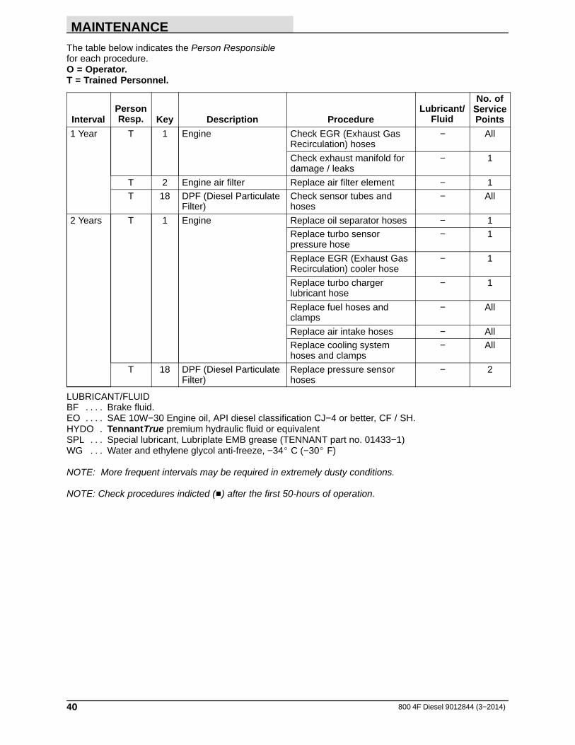
The table below indicates the Person Responsiblefor each procedure.O = Operator.T = Trained Personnel.
IntervalPersonResp. Key Description Procedure
Lubricant/Fluid
No. ofServicePoints
1 Year T 1 Engine Check EGR (Exhaust GasRecirculation) hoses
− All
Check exhaust manifold fordamage / leaks
− 1
T 2 Engine air filter Replace air filter element − 1T 18 DPF (Diesel Particulate
Filter)Check sensor tubes andhoses
− All
2 Years T 1 Engine Replace oil separator hoses − 1Replace turbo sensorpressure hose
− 1
Replace EGR (Exhaust GasRecirculation) cooler hose
− 1
Replace turbo chargerlubricant hose
− 1
Replace fuel hoses andclamps
− All
Replace air intake hoses − AllReplace cooling systemhoses and clamps
− All
T 18 DPF (Diesel ParticulateFilter)
Replace pressure sensorhoses
− 2
LUBRICANT/FLUIDBF Brake fluid.. . . .EO SAE 10W−30 Engine oil, API diesel classification CJ−4 or better, CF / SH.. . . .HYDO TennantTrue premium hydraulic fluid or equivalent.SPL Special lubricant, Lubriplate EMB grease (TENNANT part no. 01433−1). . .WG Water and ethylene glycol anti-freeze, −34� C (−30� F). . .
NOTE: More frequent intervals may be required in extremely dusty conditions.
NOTE: Check procedures indicted (�) after the first 50-hours of operation.
MAINTENANCE
41800 4F Diesel 9012844 (3−2014)
LUBRICATION
FOR SAFETY: Before leaving or servicingmachine, stop on level surface, set parkingbrake, turn off machine, and remove key.
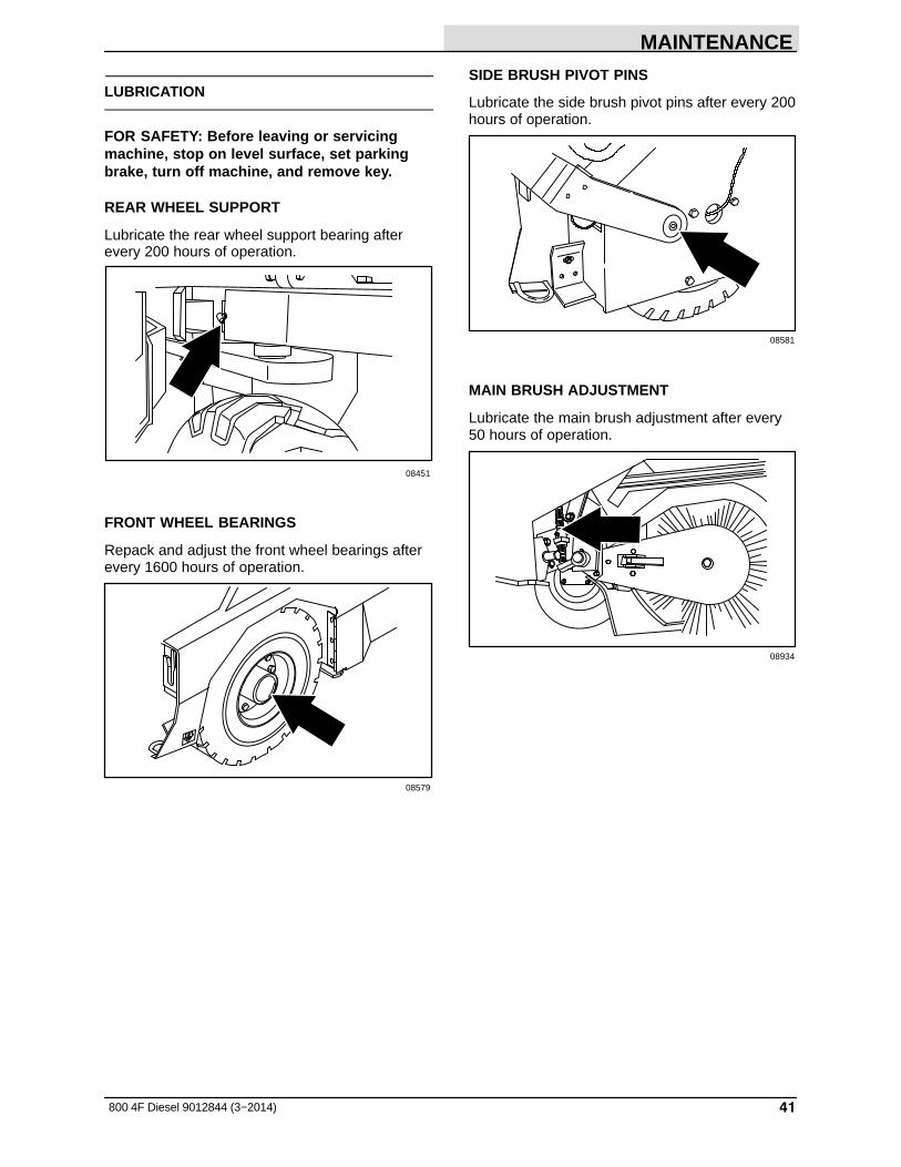
REAR WHEEL SUPPORT
Lubricate the rear wheel support bearing afterevery 200 hours of operation.
08451
FRONT WHEEL BEARINGS
Repack and adjust the front wheel bearings afterevery 1600 hours of operation.
08579
SIDE BRUSH PIVOT PINS
Lubricate the side brush pivot pins after every 200hours of operation.
08581
MAIN BRUSH ADJUSTMENT
Lubricate the main brush adjustment after every50 hours of operation.
08934
MAINTENANCE
42 800 4F Diesel 9012844 (3−2014)
HYDRAULICS
FOR SAFETY: Before leaving or servicingmachine, stop on level surface, set parkingbrake, turn off machine, and remove key.
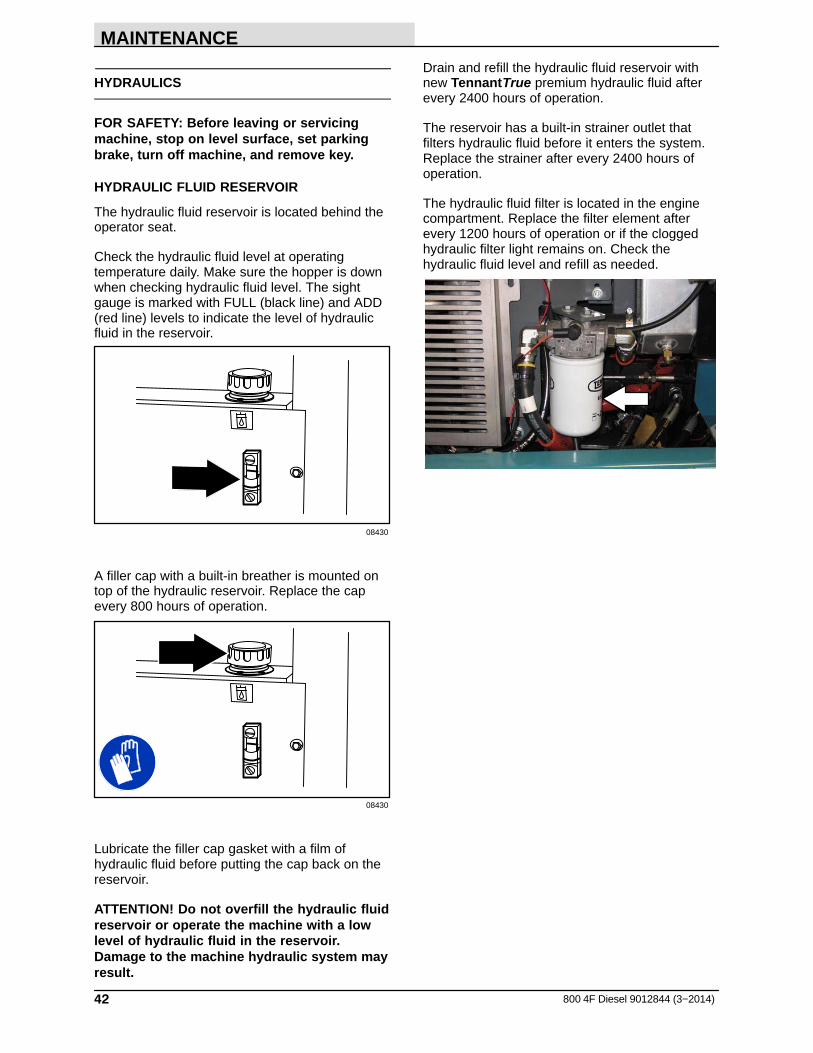
HYDRAULIC FLUID RESERVOIR
The hydraulic fluid reservoir is located behind theoperator seat.
Check the hydraulic fluid level at operatingtemperature daily. Make sure the hopper is downwhen checking hydraulic fluid level. The sightgauge is marked with FULL (black line) and ADD(red line) levels to indicate the level of hydraulicfluid in the reservoir.
08430
A filler cap with a built-in breather is mounted ontop of the hydraulic reservoir. Replace the capevery 800 hours of operation.
08430
Lubricate the filler cap gasket with a film ofhydraulic fluid before putting the cap back on thereservoir.
ATTENTION! Do not overfill the hydraulic fluidreservoir or operate the machine with a lowlevel of hydraulic fluid in the reservoir.Damage to the machine hydraulic system mayresult.
Drain and refill the hydraulic fluid reservoir withnew TennantTrue premium hydraulic fluid afterevery 2400 hours of operation.
The reservoir has a built-in strainer outlet thatfilters hydraulic fluid before it enters the system.Replace the strainer after every 2400 hours ofoperation.
The hydraulic fluid filter is located in the enginecompartment. Replace the filter element afterevery 1200 hours of operation or if the cloggedhydraulic filter light remains on. Check thehydraulic fluid level and refill as needed.

MAINTENANCE
43800 4F Diesel 9012844 (3--2015)
HYDRAULIC FLUID
There are three fluids available for differenttemperature ranges:
TennantTrue premiumhydraulic fluid (Extended Life)
PartNumber
Capacity ISOGradeViscosityIndex (VI)
Ambient AirTemperatureRanges
1057710 3.8 L(1 gal)
ISO 100VI 126 orhigher
29_ C(85_ F) orhigher
1057711 19 L(5 gal)
1057707 3.8 L(1 gal)
ISO 32VI 163 orhigher
7_ C(45_ F) orlower
1057708 19 L(5 gal)
If using a locally--available hydraulic fluid, be surethe specifications match the Tennant hydraulicfluid specifications. Substitute fluids can causepremature failure of hydraulic components.
ATTENTION! Hydraulic components dependon system hydraulic fluid for internallubrication. Malfunctions, accelerated wear,and damage will result if dirt or othercontaminants enter the hydraulic system.
HYDRAULIC HOSES
Check the hydraulic hoses after every 800 hoursof operation for wear or damage.
FOR SAFETY: When servicing machine, usecardboard to locate leaking hydraulic fluidunder pressure.
High pressure fluid escaping from a very smallhole can almost be invisible, and can cause injury.
00002
Contact appropriate personnel if a leak isdiscovered.
ATTENTION: Only use TENNANT suppliedhydraulic hoses or equivalent rated hydraulichoses.
MAINTENANCE
44 800 4F Diesel 9012844 (3−2014)
ENGINE
FOR SAFETY: Before leaving or servicingmachine, stop on level surface, set parkingbrake, turn off machine, and remove key.
ENGINE OIL
NOTE: All oil must be drained from the enginebefore a different brand of oil or a differentviscosity oil is used. Do Not mix different brandsof oil or different viscosity oil with the oil already inthe engine.
Check the engine oil level daily. Change theengine oil and oil filter after the first 50 hours ofmachine operation, and then after every 100hours of operation.
The engine oil drain is located on the engine oilpan. Drain the engine oil when it is warm.
Fill the engine with oil until the oil is between theindicator marks on the dipstick. DO NOT fill pastthe top indicator mark. The engine oil capacity is 6.6 L (7 qt) including the oil filter.
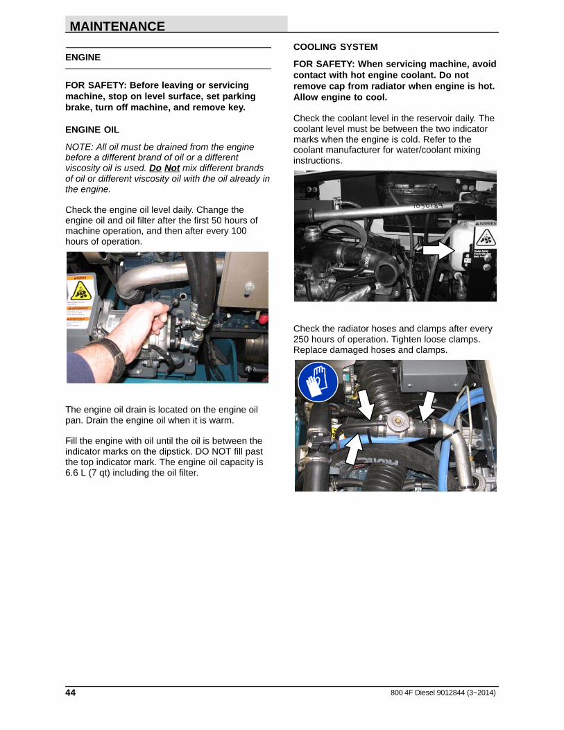
COOLING SYSTEM
FOR SAFETY: When servicing machine, avoidcontact with hot engine coolant. Do notremove cap from radiator when engine is hot.Allow engine to cool.
Check the coolant level in the reservoir daily. Thecoolant level must be between the two indicatormarks when the engine is cold. Refer to thecoolant manufacturer for water/coolant mixinginstructions.
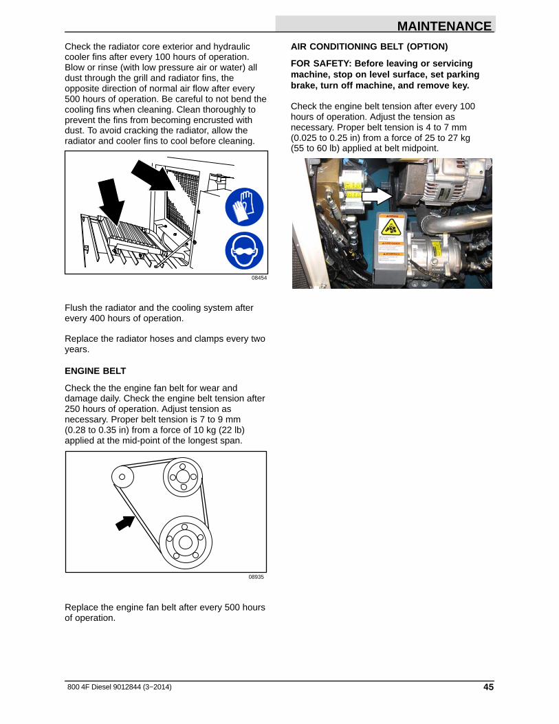
Check the radiator hoses and clamps after every250 hours of operation. Tighten loose clamps.Replace damaged hoses and clamps.
MAINTENANCE
45800 4F Diesel 9012844 (3−2014)
Check the radiator core exterior and hydrauliccooler fins after every 100 hours of operation.Blow or rinse (with low pressure air or water) alldust through the grill and radiator fins, theopposite direction of normal air flow after every500 hours of operation. Be careful to not bend thecooling fins when cleaning. Clean thoroughly toprevent the fins from becoming encrusted withdust. To avoid cracking the radiator, allow theradiator and cooler fins to cool before cleaning.
08454
Flush the radiator and the cooling system afterevery 400 hours of operation.
Replace the radiator hoses and clamps every twoyears.
ENGINE BELT
Check the the engine fan belt for wear anddamage daily. Check the engine belt tension after250 hours of operation. Adjust tension asnecessary. Proper belt tension is 7 to 9 mm (0.28 to 0.35 in) from a force of 10 kg (22 lb)applied at the mid-point of the longest span.
08935
Replace the engine fan belt after every 500 hoursof operation.
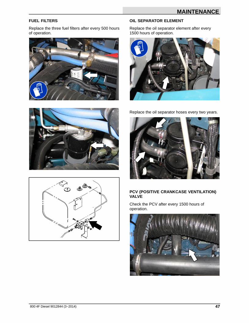
AIR CONDITIONING BELT (OPTION)
FOR SAFETY: Before leaving or servicingmachine, stop on level surface, set parkingbrake, turn off machine, and remove key.
Check the engine belt tension after every 100hours of operation. Adjust the tension asnecessary. Proper belt tension is 4 to 7 mm(0.025 to 0.25 in) from a force of 25 to 27 kg (55 to 60 lb) applied at belt midpoint.

MAINTENANCE
46 800 4F Diesel 9012844 (3−2014)
DRAINING WATER FROM THE WATER / FUELSEPARATOR
FOR SAFETY: When servicing machine, keepflames and sparks away from fuel systemservice area. Keep area well ventilated.
Drain water from the water / fuel separator afterevery 50 hours of operation.
Turn the key to the on position without starting theengine.
Turn the water / fuel separator fitting located onthe bottom of the water / fuel separatorapproximately a half turn to open the drain.
Press the pump several times to drain the waterfrom the water / fuel separator.
Close the water / fuel separator fitting.
FUEL LINES
Check the fuel lines after every 50 hours ofoperation. If a clamp band is loose, apply oil to thescrew of the band and securely tighten the band.
The rubber fuel lines can become worn−outwhether the engine has been used much or not.Replace the fuel lines and clamp bands every twoyears.
FOR SAFETY: When servicing machine, keepflames and sparks away from fuel systemservice area. Keep area well ventilated.
If the fuel lines and clamp bands are found wornor damaged before two years; replace or repairthem at once. Bleed the fuel system afterreplacement of any fuel lines, see PRIMING THEFUEL SYSTEM. When the fuel lines are notinstalled, plug both ends with clean cloth or paperto prevent dirt from entering the lines. Dirt in thelines can cause a fuel injection pump malfunction.
PRIMING THE FUEL SYSTEM
Typical diesel fuel systems require priming toremove pockets of air from the fuel lines and fuelcomponents. This is usually required after runningout of fuel, changing fuel filter elements orrepairing a fuel system component. Air in the fuelprevents smooth engine operation. Refer to theengine manufacturer’s manual for additionalinformation.
MAINTENANCE
47800 4F Diesel 9012844 (3−2014)
FUEL FILTERS
Replace the three fuel filters after every 500 hoursof operation.
OIL SEPARATOR ELEMENT
Replace the oil separator element after every1500 hours of operation.
Replace the oil separator hoses every two years.
PCV (POSITIVE CRANKCASE VENTILATION)VALVE
Check the PCV after every 1500 hours ofoperation.
MAINTENANCE
48 800 4F Diesel 9012844 (3−2014)
EGR (EXHAUST GAS RECIRCULATION)COOLER
Check the EGR cooler for damage after every1500 hours of operation.
Check the EGR tubing and hoses for leaks anddamage yearly.
Replace the EGR cooler hoses every two years.
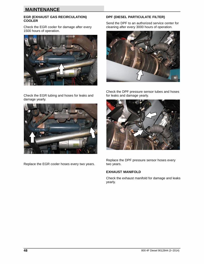
DPF (DIESEL PARTICULATE FILTER)
Send the DPF to an authorized service center forcleaning after every 3000 hours of operation.
Check the DPF pressure sensor tubes and hosesfor leaks and damage yearly.
Replace the DPF pressure sensor hoses everytwo years.
EXHAUST MANIFOLD
Check the exhaust manifold for damage and leaksyearly.

MAINTENANCE
49800 4F Diesel 9012844 (3−2014)
TURBO CHARGER
Check the turbo charger for leaks after every3000 hours of operation.
Replace the turbo charger sensor pressure hoseevery two years.
Replace the turbo charger lubricant hose everytwo years.
VALVE CLEARANCE
Check and adjust the valve clearance to 0.18 to0.22 mm (0.0071 to 0.0086 in) while the engine iscold after every 1000 hours of operation.
AIR INTAKE HOSES
Check the air intake hoses leaks and damageafter every 250 hours of operation.
Replace the air intake hoses every two years.

MAINTENANCE
50 800 4F Diesel 9012844 (3−2014)
AIR FILTER INDICATOR
Check the indicator daily. The indicator red linewill move as the air filter element fills with dirt. Donot replace the air filter element until the red linereaches 5 kPa (20 in H2O) and the “SERVICEWHEN RED” window is filled with red. The enginemust be running to get an accurate air indicatorreading.
FOR SAFETY: When servicing machine, avoidmoving parts. Do not wear loose clothing,jewelry, and secure long hair.
AIR FILTER ASSEMBLY
Empty the engine air filter dust cap daily.
Clean the air filter element after every 250 hoursof operation. Replace the air filter element yearly.
FOR SAFETY: Before leaving or servicingmachine, stop on level surface, set parkingbrake, turn off machine, and remove key.
Replace the air filter element when the air filterindicator shows restriction in the air intake systemor the filter element is damaged. Refer to AIRFILTER INDICATOR.
Remove the filter element. Carefully clean the endcap and the interior of the housing with a dampcloth. Clean the housing sealing surfaces.
Install the filter element into the air filter housingand reinstall the dust cap with the water drainpointing down.
Push the reset button on the end of the indicatorto reset the air filter indicator after replacing theair filter element.
MAINTENANCE
51800 4F Diesel 9012844 (3−2014)
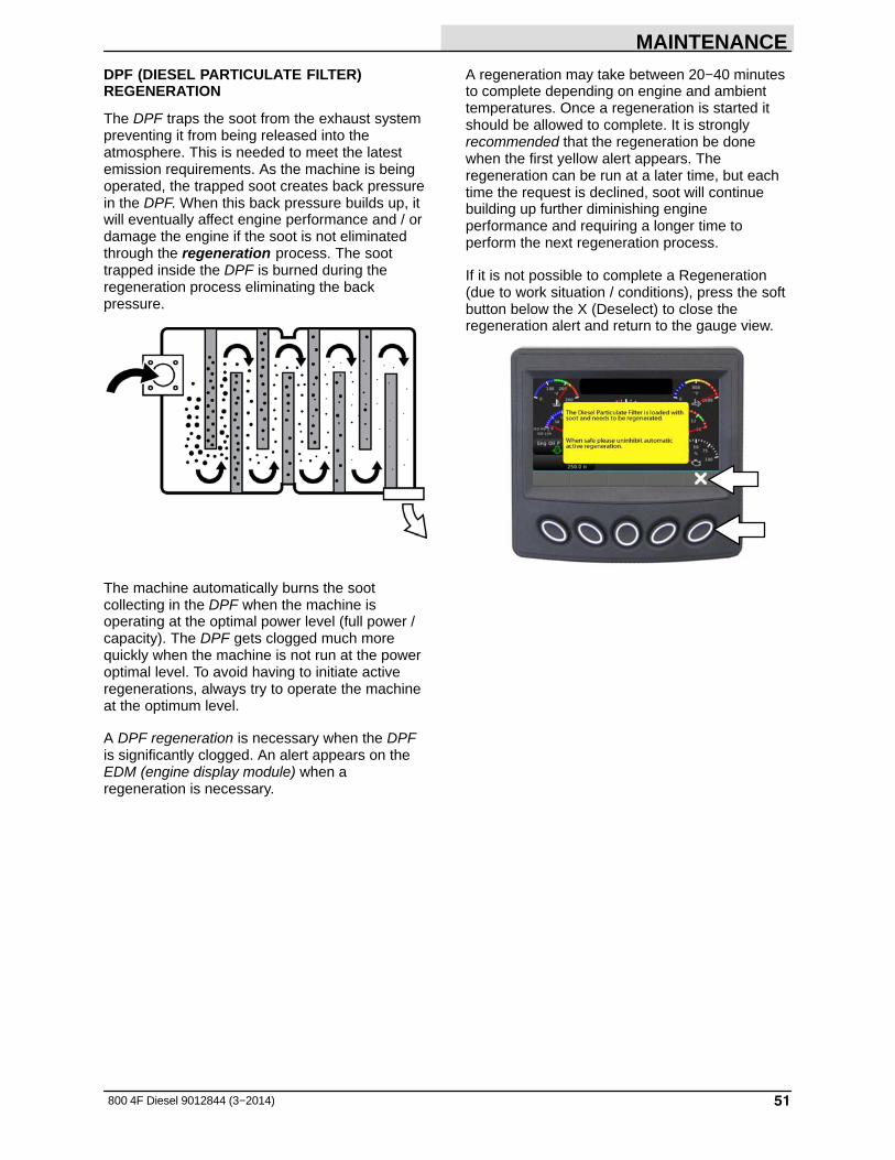
DPF (DIESEL PARTICULATE FILTER)REGENERATION
The DPF traps the soot from the exhaust systempreventing it from being released into theatmosphere. This is needed to meet the latestemission requirements. As the machine is beingoperated, the trapped soot creates back pressurein the DPF. When this back pressure builds up, itwill eventually affect engine performance and / ordamage the engine if the soot is not eliminatedthrough the regeneration process. The soottrapped inside the DPF is burned during theregeneration process eliminating the backpressure.
The machine automatically burns the sootcollecting in the DPF when the machine isoperating at the optimal power level (full power /capacity). The DPF gets clogged much morequickly when the machine is not run at the poweroptimal level. To avoid having to initiate activeregenerations, always try to operate the machineat the optimum level.
A DPF regeneration is necessary when the DPFis significantly clogged. An alert appears on theEDM (engine display module) when aregeneration is necessary.
A regeneration may take between 20−40 minutesto complete depending on engine and ambienttemperatures. Once a regeneration is started itshould be allowed to complete. It is stronglyrecommended that the regeneration be donewhen the first yellow alert appears. Theregeneration can be run at a later time, but eachtime the request is declined, soot will continuebuilding up further diminishing engineperformance and requiring a longer time toperform the next regeneration process.
If it is not possible to complete a Regeneration(due to work situation / conditions), press the softbutton below the X (Deselect) to close theregeneration alert and return to the gauge view.
MAINTENANCE
52 800 4F Diesel 9012844 (3−2014)
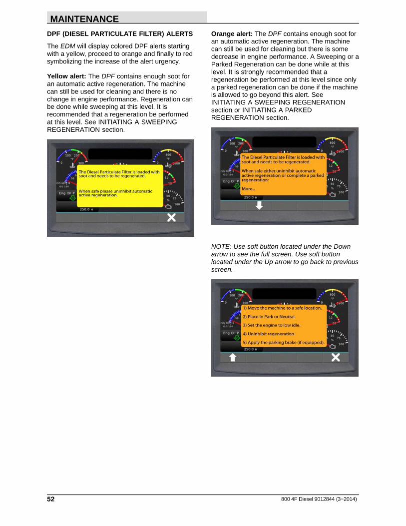
DPF (DIESEL PARTICULATE FILTER) ALERTS
The EDM will display colored DPF alerts startingwith a yellow, proceed to orange and finally to redsymbolizing the increase of the alert urgency.
Yellow alert: The DPF contains enough soot foran automatic active regeneration. The machinecan still be used for cleaning and there is nochange in engine performance. Regeneration canbe done while sweeping at this level. It isrecommended that a regeneration be performedat this level. See INITIATING A SWEEPINGREGENERATION section.
Orange alert: The DPF contains enough soot foran automatic active regeneration. The machinecan still be used for cleaning but there is somedecrease in engine performance. A Sweeping or aParked Regeneration can be done while at thislevel. It is strongly recommended that aregeneration be performed at this level since onlya parked regeneration can be done if the machineis allowed to go beyond this alert. SeeINITIATING A SWEEPING REGENERATIONsection or INITIATING A PARKEDREGENERATION section.
NOTE: Use soft button located under the Downarrow to see the full screen. Use soft buttonlocated under the Up arrow to go back to previousscreen.

MAINTENANCE
53800 4F Diesel 9012844 (3−2014)
Red (URGENT) alert: The DPF is extremelyloaded with soot and needs a PARKEDregeneration. The machine should NO LONGERbe used for cleaning as there is significantdecrease in engine performance. It is imperativethat an active parked regeneration be performedimmediately after receiving this alert since this isthe last alert that allows an operator initiatedparked regeneration. See INITIATING A PARKEDREGENERATION section.
NOTE: Use soft button located under the Downarrow to see the full screen. Use soft buttonlocated under the Up arrow to go back to previousscreen.
Refer to INITIATING A PARKEDREGENERATION for instructions how to safelycomplete a parked regeneration.
2nd Red (URGENT) alert: If the first Red alert isignored, the operator can no longer initiate theregeneration process. A qualified serviceperson will need to initiate the regeneration.Park the machine immediately and call a qualifiedservice person.
NOTE: All DPF related repairs due to the ignoredregeneration alerts are not covered under themachine warranty.
3rd Red (URGENT) alert: If the 2nd Red alert isignored and the machine is not immediatelyturned off, the DPF will need to be either replacedor removed from the machine and sent to aqualified cleaning facility to be cleaned. This is avery costly repair and is not covered under themachine warranty.

MAINTENANCE
54 800 4F Diesel 9012844 (3−2014)
DPF (DIESEL PARTICULATE FILTER) STATUSICONS
Monitor the color coded DPF Status Icons forDPF status.
StatusIcon Description
Parking Brake − Green icondisplays when the parking brake isset.
Transmission Neutral − Green icondisplays when the directional pedalis in neutral.
Engine Exhaust High TemperatureLamp − Red icon displays duringactive DPF regeneration when theDPF outlet temperature is hotenough for a regeneration.
DPF Lamp Command − Red iconis on solid during regeneration orblinking to request a parkedregeneration. Yellow Icon isilluminated solid to requestautomatic active regenerationwhen regeneration is inhibited.
DPF Regeneration set to Inhibit −Displays when the machine or theoperator has inhibited aregeneration.
INITIATING A SWEEPING REGENERATION
The EDM defaults to the Inhibited setting. TheDPF inhibited icon illuminates when aregeneration is inhibited. Un−Inhibit the system toinitiate an active regeneration.
1. Press the soft button under DPF Commandsto access the Un−Inhibit Regen command.
2. Select Un−Inhibit Regen from the menu andfollow the on screen directions.
3. The EDM returns to the Inhibit default afterthe Un−Inhibited regeneration is complete.

MAINTENANCE
55800 4F Diesel 9012844 (3−2014)
INITIATING A PARKED REGENERATION
FOR SAFETY: Before initiating an activeparked regeneration, stop on a level surfacein a well ventilated open area. Park in lowtraffic areas away from pedestrians and otherequipment. Do not park near combustiblematerials, dusts, gases, or liquids. Do notpark indoors or in enclosed areas. Set parkingbrake. Do not leave machine unattended.
NOTE: All EDM (engine display module) errorcodes must be cleared before placing themachine into regeneration. The EDM will not allowthe engine to regenerate if there are error codeson the display.
1. Drive the machine to a safe area forcompleting parked regeneration and releasethe propel pedal into the neutral position.
NOTE: The directional pedal must remain in theneutral position and all sweeping functions mustremain off until regeneration is completed.
2. Press the EDM soft button under 1350 RPMto lower the engine to idle.
3. Set the parking brake. The parking brake iconon the EDM will be illuminated.
4. Read and follow the instructions on the EDM.
5. Press the soft button under DPF Commandsto access the Un−Inhibit Regen command.
6. Select Un−Inhibit Regen from the menu.
MAINTENANCE
56 800 4F Diesel 9012844 (3−2014)
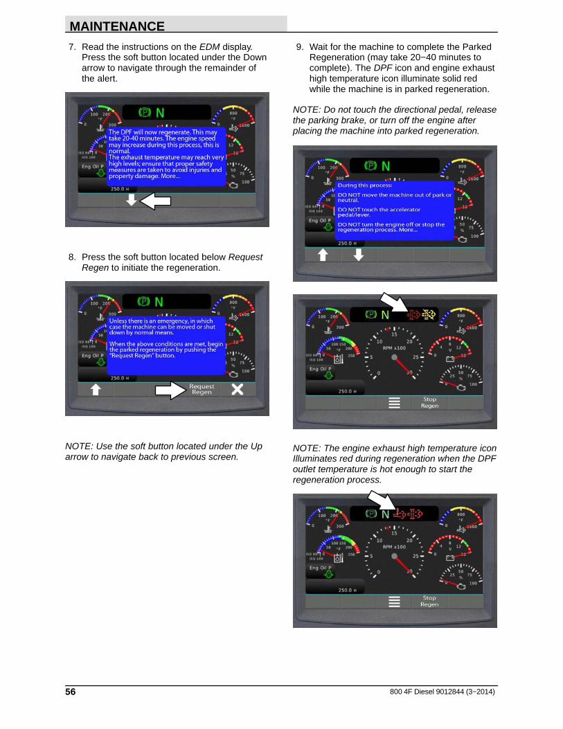
7. Read the instructions on the EDM display.Press the soft button located under the Downarrow to navigate through the remainder ofthe alert.
8. Press the soft button located below RequestRegen to initiate the regeneration.
NOTE: Use the soft button located under the Uparrow to navigate back to previous screen.
9. Wait for the machine to complete the ParkedRegeneration (may take 20−40 minutes tocomplete). The DPF icon and engine exhausthigh temperature icon illuminate solid redwhile the machine is in parked regeneration.
NOTE: Do not touch the directional pedal, releasethe parking brake, or turn off the engine afterplacing the machine into parked regeneration.
NOTE: The engine exhaust high temperature iconIlluminates red during regeneration when the DPFoutlet temperature is hot enough to start theregeneration process.

MAINTENANCE
57800 4F Diesel 9012844 (3−2014)
NOTE: Do not touch the directional pedal, releasethe parking brake, or turn off the engine after themachine is placed into parked regeneration. Donot stop the parked regeneration unless there areextenuating circumstances (safety issues) thatrequire the parked regeneration to be prematurelystopped. Only if necessary, press the soft buttonlocated below Stop Regen to stop theregeneration.
NOTE: After a prematurely stopped parkedregeneration the EDM may again display an alertthat a regeneration is necessary the next time themachine is started and allowed to warm up to atemperature hot enough for a regeneration to beinitiated, When circumstances allow, initiateanother regeneration.
10. “DPF regeneration is complete” appears onthe EDM display when the parkedregeneration is complete. Press the softbutton under X (Deselect) to close themessage and return to the gauge display. Themachine is ready for use.
MAINTENANCE
58 800 4F Diesel 9012844 (3−2014)
BATTERY
Clean and tighten the battery connections afterthe first 50 hours of operation and after every 800hours after that. Do not remove the vent plugsfrom the battery or add water to the battery.
Remove the engine compartment access panellocated in the operator compartment to accessthe battery.
FOR SAFETY: When servicing machine, avoidcontact with battery acid.
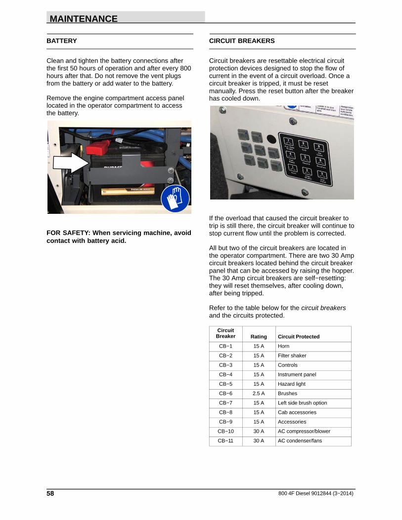
CIRCUIT BREAKERS
Circuit breakers are resettable electrical circuitprotection devices designed to stop the flow ofcurrent in the event of a circuit overload. Once acircuit breaker is tripped, it must be resetmanually. Press the reset button after the breakerhas cooled down.
If the overload that caused the circuit breaker totrip is still there, the circuit breaker will continue tostop current flow until the problem is corrected.
All but two of the circuit breakers are located inthe operator compartment. There are two 30 Ampcircuit breakers located behind the circuit breakerpanel that can be accessed by raising the hopper.The 30 Amp circuit breakers are self−resetting:they will reset themselves, after cooling down,after being tripped.
Refer to the table below for the circuit breakersand the circuits protected.
CircuitBreaker Rating Circuit Protected
CB−1 15 A Horn
CB−2 15 A Filter shaker
CB−3 15 A Controls
CB−4 15 A Instrument panel
CB−5 15 A Hazard light
CB−6 2.5 A Brushes
CB−7 15 A Left side brush option
CB−8 15 A Cab accessories
CB−9 15 A Accessories
CB−10 30 A AC compressor/blower
CB−11 30 A AC condenser/fans

MAINTENANCE
59800 4F Diesel 9012844 (3−2014)
DEBRIS HOPPER
The dust filters filter the air pulled up from thehopper. The dust filters are equipped with ashaker to remove the accumulated dust particles.The dust filters shaker is operated by the filtershaker switch.
Shake the dust filters before dumping the hopperand at the end of every work shift. Avoid shakingthe filters while the hopper is in a rolled outposition. Check and clean the dust filters every 50 hours of operation. Extremely dusty conditionsmay require more frequent cleaning of dust filters.Replace damaged dust filters.
REMOVING OR REPLACING THE HOPPERDUST FILTER
NOTE: Clean the filter more often if used inextremely dusty conditions.
1. Shake the hopper dust filter.
2. Stop the engine and set the machine parkingbrake.
FOR SAFETY: Before leaving or servicingmachine, stop on level surface, set parkingbrake, turn off machine, and remove key.
3. Open the hopper cover.
4. Disconnect the shaker motor wire connectors.
5. Remove the four retaining screws from thefilter shaker frame.
08591
6. Pull the filter shaker frame out of the hopper.
7. Carefully turn over the shaker frame andelement.
8. Loosen the four filter retaining screws fromthe shaker frame.
08592
9. Remove the retainer ring from the shakerframe. Remove the filter.
10. Make sure the prescreen wrap is tightlywrapped around and securely fastened on thenew filter element. Put the new filter on thefilter shaker frame.
11. Place the retainer ring over the filter. Makesure the retaining ring fits inside the lip of thefilter element all the way around. Line up theslots on the retainer ring with the retainingscrews holes.
08593
12. Mount using the retaining screws.
13. Check the seal on the shaker frame fordamage. Make sure the vibration isolators aremounted in all four corners of the filter shakerframe.
14. Put the filter and shaker frame in the hopper.
15. Install the four retaining screws and tighten.
16. Connect the shaker motor wire connectors.

MAINTENANCE
60 800 4F Diesel 9012844 (3−2014)
CLEANING THE HOPPER DUST FILTER
To clean the dust filters, use one of the followingmethods:
� SHAKING − Press the filter shaker switch.
� AIR − Blow compressed air through the dustfilter from the inside. This may be done withthe dust filter in the machine, or for moreefficient cleaning remove the dust filter fromthe machine and the prescreen wrap from thefilter element.
08594
� WATER − Remove the fabric prescreen wrapfrom the filter element. Wash the prescreenwrap in a water and mild detergent solution.Rinse the prescreen wrap until it is clean. Airdry the wet prescreen wrap; do not usecompressed air. NEVER wash the filterelement with water.
THERMO SENTRY
The Thermo Sentry senses the temperature of theair pulled up from the hopper. If there is a fire inthe hopper, the Thermo Sentry stops the vacuumfan and cuts off the air flow. The Thermo Sentry islocated on the vacuum fan housing.
Press the reset button to reset the ThermoSentry.
08928
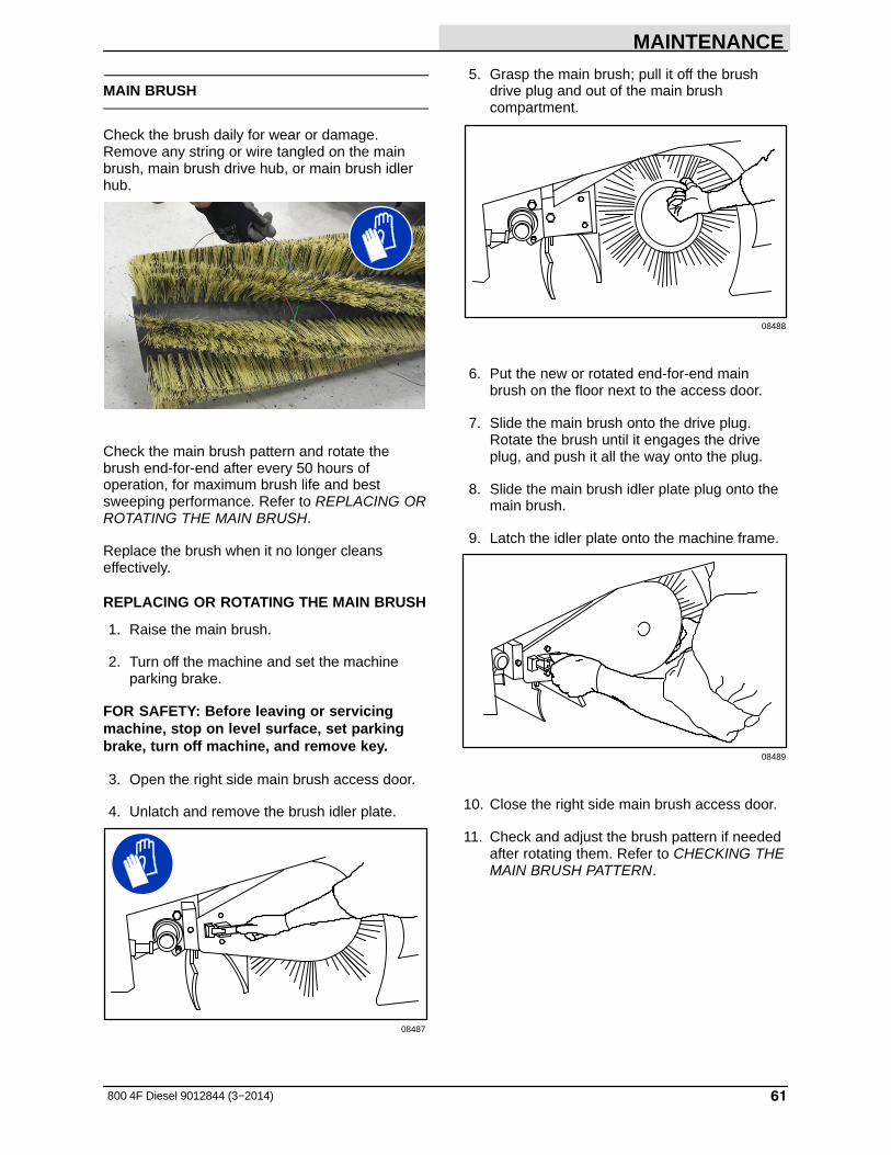
MAINTENANCE
61800 4F Diesel 9012844 (3−2014)
MAIN BRUSH
Check the brush daily for wear or damage.Remove any string or wire tangled on the mainbrush, main brush drive hub, or main brush idlerhub.
Check the main brush pattern and rotate thebrush end-for-end after every 50 hours ofoperation, for maximum brush life and bestsweeping performance. Refer to REPLACING ORROTATING THE MAIN BRUSH.
Replace the brush when it no longer cleanseffectively.
REPLACING OR ROTATING THE MAIN BRUSH
1. Raise the main brush.
2. Turn off the machine and set the machineparking brake.
FOR SAFETY: Before leaving or servicingmachine, stop on level surface, set parkingbrake, turn off machine, and remove key.
3. Open the right side main brush access door.
4. Unlatch and remove the brush idler plate.
08487
5. Grasp the main brush; pull it off the brushdrive plug and out of the main brushcompartment.
08488
6. Put the new or rotated end-for-end mainbrush on the floor next to the access door.
7. Slide the main brush onto the drive plug.Rotate the brush until it engages the driveplug, and push it all the way onto the plug.
8. Slide the main brush idler plate plug onto themain brush.
9. Latch the idler plate onto the machine frame.
08489
10. Close the right side main brush access door.
11. Check and adjust the brush pattern if neededafter rotating them. Refer to CHECKING THEMAIN BRUSH PATTERN.
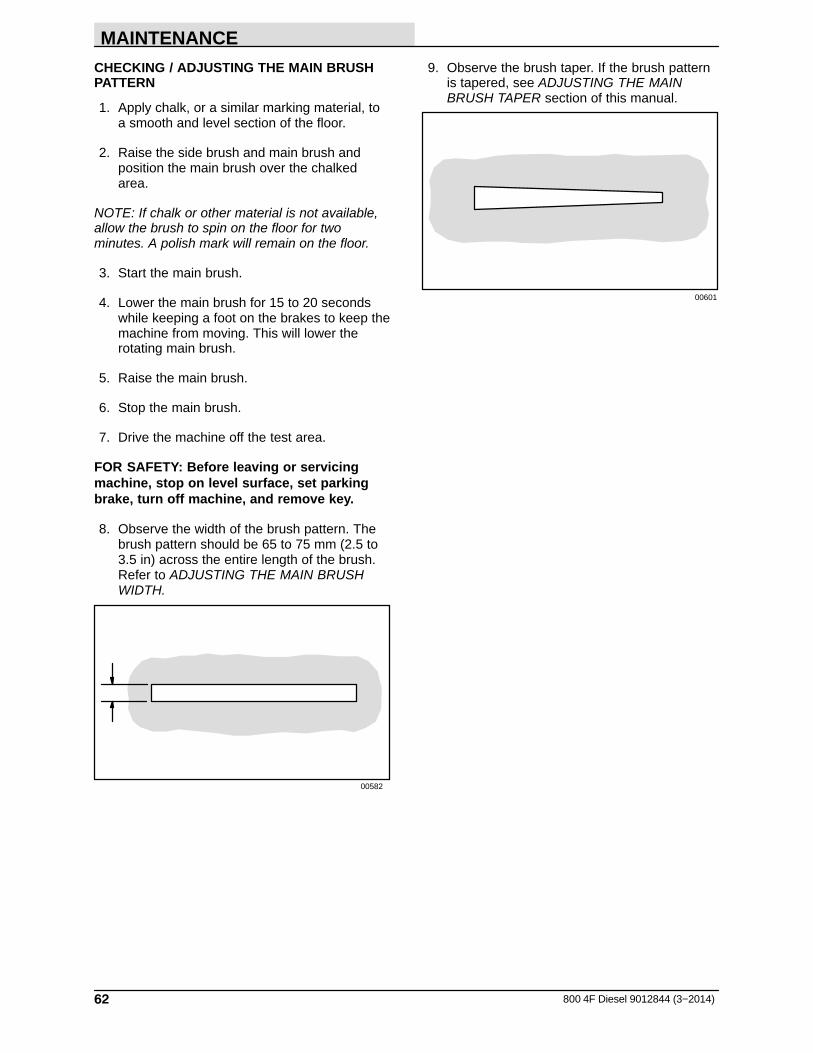
MAINTENANCE
62 800 4F Diesel 9012844 (3−2014)
CHECKING / ADJUSTING THE MAIN BRUSHPATTERN
1. Apply chalk, or a similar marking material, toa smooth and level section of the floor.
2. Raise the side brush and main brush andposition the main brush over the chalkedarea.
NOTE: If chalk or other material is not available,allow the brush to spin on the floor for twominutes. A polish mark will remain on the floor.
3. Start the main brush.
4. Lower the main brush for 15 to 20 secondswhile keeping a foot on the brakes to keep themachine from moving. This will lower therotating main brush.
5. Raise the main brush.
6. Stop the main brush.
7. Drive the machine off the test area.
FOR SAFETY: Before leaving or servicingmachine, stop on level surface, set parkingbrake, turn off machine, and remove key.
8. Observe the width of the brush pattern. Thebrush pattern should be 65 to 75 mm (2.5 to3.5 in) across the entire length of the brush.Refer to ADJUSTING THE MAIN BRUSHWIDTH.
00582
9. Observe the brush taper. If the brush patternis tapered, see ADJUSTING THE MAINBRUSH TAPER section of this manual.
00601

MAINTENANCE
63800 4F Diesel 9012844 (3−2014)
ADJUSTING THE MAIN BRUSH WIDTH
FOR SAFETY: Before leaving or servicingmachine, stop on level surface, set parkingbrake, turn off machine, and remove key.
1. Observe the width of the brush pattern.
2. To increase the width of the main brushpattern, turn the main brush down pressureknob counter-clockwise.
To decrease the width of the main brushpattern, turn the main brush down pressureknob clockwise.
ADJUSTING THE MAIN BRUSH TAPER
FOR SAFETY: Before leaving or servicingmachine, stop on level surface, set parkingbrake, turn off machine, and remove key.
1. Observe the brush taper.
2. Loosen the brush drive end plate mountingbolts.
08450
3. Turn the taper adjustment nut counter-clockwise to increase the pattern width at thebrush drive end, and clockwise to decreasethe pattern width at the brush drive end.Tighten the drive end plate mounting bolts.
08490
4. Check the main brush pattern and readjust asnecessary. Then adjust the width of the mainbrush pattern.

MAINTENANCE
64 800 4F Diesel 9012844 (3−2014)
SIDE BRUSH(ES)
Check the brush(es) daily for wear or damage.Remove any string or wire found tangled in thebrush(es) or drive hub(s).
Replace the brush(es) when it no longer cleanseffectively.
REPLACING THE SIDE BRUSH
1. Empty the debris hopper.
2. Set the machine parking brake.
3. Raise the hopper.
4. Turn off the engine.
FOR SAFETY: Before leaving or servicingmachine, stop on level surface, set parkingbrake, turn off machine, and remove key.
5. Remove the side brush retaining pin from theside brush drive shaft.
08466
6. Slide the side brush off the side brush driveshaft.
NOTE: Remove the drive hub and put it on thenew brush if one is not installed.
7. Slide the new side brush onto the side brushdrive shaft.
8. Insert the side brush retaining pin through theside brush hub and shaft and secure.
9. Disengage the hopper support bar and lowerthe hopper.
10. Adjust the side brush pattern with the sidebrush down pressure knob.
ADJUSTING THE SIDE BRUSH PATTERN
Check the side brush pattern daily. The side brushbristles should touch the floor in the patternsshown in the illustration.
350327
Turn the knob counterclockwise to increase thebrush pressure and clockwise to decrease thebrush pressure.

MAINTENANCE
65800 4F Diesel 9012844 (3−2014)
SKIRTS AND SEALS
FOR SAFETY: Before leaving or servicingmachine, stop on level surface, set parkingbrake, turn off machine, and remove key.
HOPPER LIP SKIRTS
The hopper lip skirts are located on the bottomrear of the hopper. The skirts float over debris andhelp deflect that debris into the hopper. The topskirt is segmented.
Check the hopper lip skirts for wear or damagedaily.
Replace the hopper lip skirts when they no longertouch the floor.
08491
HOPPER SIDE SKIRT
The hopper side skirt is located on the left side ofthe hopper.
Check the hopper side skirt for wear or damageand adjustment daily.
08492
BRUSH COMPARTMENT SKIRTS
The brush compartment skirts are located on thebottom of each of the two main brush doors andaround the ends of the brush on the main frame.The inside brush door skirt should touch the floor,and the outside brush door skirt should clear thefloor by 3 to 5 mm (0.12 to 0.25 in).
Check the skirts for wear or damage andadjustment daily.
NOTE: The brush door skirts have slotted holes toallow for a ground clearance adjustment. Thedoor must be closed for proper adjustment.
NOTE: Tire pressure will affect skirt clearances.
08493
REAR SKIRTS
The two rear skirts are located on the bottom rearof the main brush compartment. The vertical skirtshould clear the floor up to 20 mm (0.75 in) industy conditions, and touch the floor otherwise.The recirculation skirt is self-adjusting.
Check the skirts for wear or damage andadjustment daily.
NOTE: Tire pressure will affect skirt clearances.
08494

MAINTENANCE
66 800 4F Diesel 9012844 (3−2014)
BRUSH DOOR SEALS
The brush door seals are located on both mainbrush doors and on corresponding portions of themain frame.
Check the seals for wear or damage after every 100 hours of operation.
08495
HOPPER DUST SEAL
The hopper dust seal is located inside the hopper.It seals the hopper filter compartment.
Check the seal for wear or damage after every 100 hours of operation.
08498
HOPPER SEALS
The hopper seals are located on the top and sideportions of the machine frame that contact thehopper.
Check the seals for wear or damage after every 100 hours of operation.
08496
HOPPER DOOR SEALS
The hopper door seals are located on the hopperdoor. They seal the hopper when the hopper dooris closed.
Check the seals for wear or damage after every 100 hours of operation.
08497
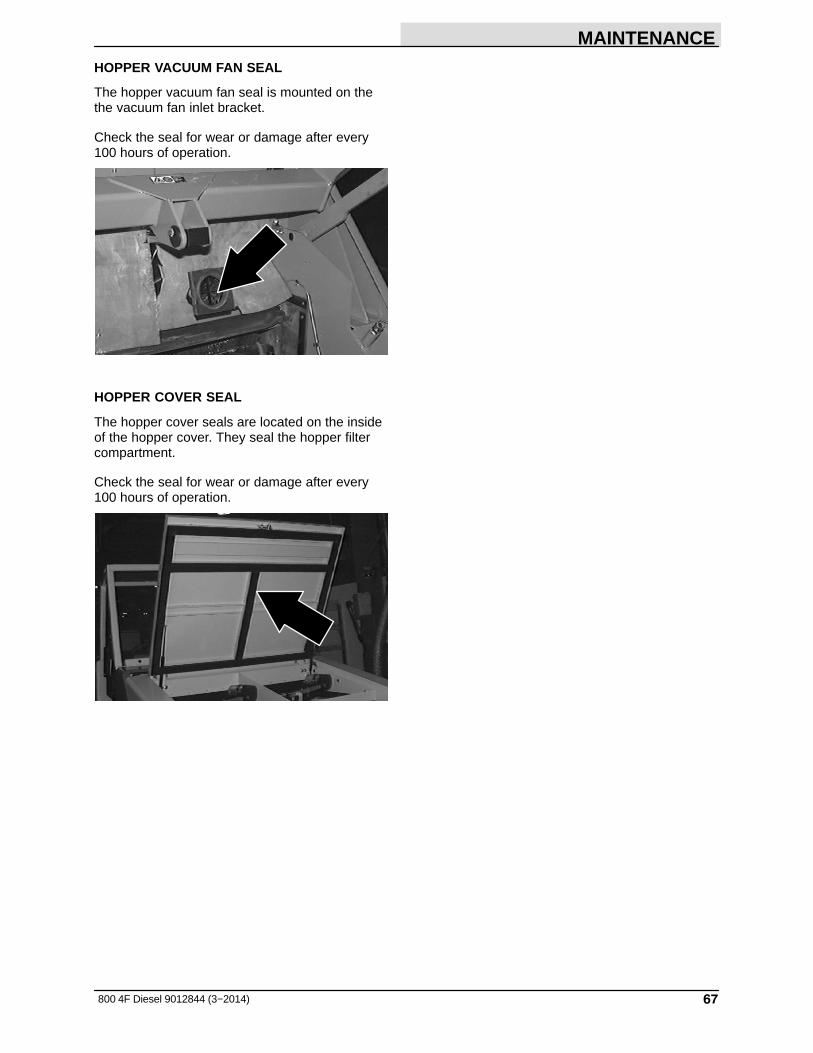
MAINTENANCE
67800 4F Diesel 9012844 (3−2014)
HOPPER VACUUM FAN SEAL
The hopper vacuum fan seal is mounted on thethe vacuum fan inlet bracket.
Check the seal for wear or damage after every 100 hours of operation.
HOPPER COVER SEAL
The hopper cover seals are located on the insideof the hopper cover. They seal the hopper filtercompartment.
Check the seal for wear or damage after every 100 hours of operation.

MAINTENANCE
68 800 4F Diesel 9012844 (3−2014)
BRAKES AND TIRES
SERVICE BRAKES
FOR SAFETY: Before leaving or servicingmachine, stop on level surface, set parkingbrake, turn off machine, and remove key.
The hydraulic service brakes are located on thefront wheels.
The master brake cylinder is located on the firewall.
Check the master brake cylinder fluid level afterevery 400 hours of operation.
08501
PARKING BRAKE
FOR SAFETY: Before leaving or servicingmachine, stop on level surface, set parkingbrake, turn off machine, and remove key.
Adjust the parking brake whenever it becomesvery easy to set, when the machine rolls aftersetting it, and after every 200 hours of operation.
TIRES
The standard machine tires are pneumatic.
Check the tire pressure after every 100 hours ofoperation. The proper tire air pressure is 690 − 758 kPa (100 − 110 psi).
08575
FRONT / REAR WHEELS
Torque the front wheel nuts twice in the patternshown to 169 to 183 Nm (125 to 135 ft lb) afterthe first 50-hours of operation, and after every800 hours of operation.
Torque the rear wheel nuts twice in the patternshown to 122 to 155 Nm (90 to 110 ft lb) after thefirst 50 hours of operation, and after every 800hours of operation.
2
3
4
1
5

MAINTENANCE
69800 4F Diesel 9012844 (3−2014)
PROPELLING MOTOR
Torque the shaft nut to 270 Nm (200 ft lb) afterthe first 50 hours of operation and after every 800 hours thereafter.
AIR CONDITIONER FILTER (OPTION)
Clean the air conditioner filter after every 100hours of operation. Replace the air conditionerfilter if it is damaged.

MAINTENANCE
70 800 4F Diesel 9012844 (3−2014)
PUSHING, TOWING, AND TRANSPORTINGTHE MACHINE
PUSHING OR TOWING THE MACHINE
If the machine becomes disabled, it can bepushed from the front or rear, but only towed fromthe rear.
The propelling pump has a bypass valve toprevent damage to the hydraulic system when themachine is being pushed or towed. This valveallows a disabled machine to be moved for a veryshort distance and at a speed to not exceed 1.6 kp/h (1 mph). The machine is NOT intendedto be pushed or towed a long distance or at a highspeed.
08576
ATTENTION! Do not push or tow machine fora long distance and without using the bypassvalve, or the machine hydraulic system maybe damaged.
Turn the bypass valve 90� from the normalposition before pushing or towing the machine.The illustration shows the bypass valve in thepushing or towing position.
Return the bypass valve to the normal positionwhen through pushing or towing the machine.

MAINTENANCE
71800 4F Diesel 9012844 (3−2014)
TRANSPORTING THE MACHINE
1. Position the machine at the loading edge ofthe truck or trailer.
FOR SAFETY: When loading/unloadingmachine onto/off truck or trailer, empty debrishopper before loading machine.
2. If the loading surface is not horizontal or ishigher than 380 mm (15 in) from the ground,use a winch to load machine.
If the loading surface is horizontal AND is 380mm (15 in) or less from the ground, themachine may be driven onto the truck ortrailer.
FOR SAFETY: When loading machine ontotruck or trailer, use winch. Do not drive themachine onto the truck or trailer unless theloading surface is horizontal AND is 380 mm(15 in) or less from the ground.
3. To winch the machine onto the truck or trailer,attach the winching chains to the rear tiedown locations.
The rear tie-down locations are through theU−bolt section of the main frame under theside bumpers toward the rear.
4. Turn the bypass valve 90� from the normalposition before winching the machine onto thetruck or trailer. See PUSHING OR TOWINGTHE MACHINE section of this manual. Makesure the machine is centered.
08576

MAINTENANCE
72 800 4F Diesel 9012844 (3−2014)
5. Position the machine onto the truck or traileras far as possible. If the machine starts toveer off the center line of the truck or trailer,stop and turn the steering wheel to center themachine.
6. Set the parking brake and block the machinetires. Tie down the machine to the truck ortrailer before transporting.
The two front tie−down locations are throughthe U−bolt section of the main frame in frontof the wheels.
The two rear tie−down locations are throughthe U−bolt section of the main frame underthe side bumpers toward the rear.
7. If the loading surface is not horizontal or ishigher than 380 mm (15 in) from the ground,use a winch to unload machine.
If the loading surface is horizontal AND is 380 mm (15 in) or less from the ground, themachine may be driven off the truck or trailer.
FOR SAFETY: When unloading machine offtruck or trailer, use winch. Do not drive themachine off the truck or trailer unless theloading surface is horizontal AND is 380 mm(15 in) or less from the ground.
8. Return the bypass valve to the normalposition when through loading the machine.Refer to PUSHING OR TOWING THEMACHINE section of this manual.
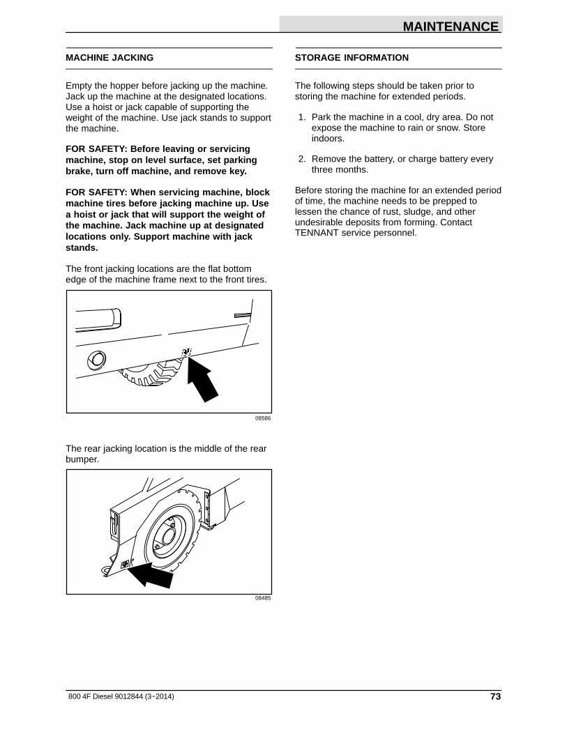
MAINTENANCE
73800 4F Diesel 9012844 (3−2014)
MACHINE JACKING
Empty the hopper before jacking up the machine.Jack up the machine at the designated locations.Use a hoist or jack capable of supporting theweight of the machine. Use jack stands to supportthe machine.
FOR SAFETY: Before leaving or servicingmachine, stop on level surface, set parkingbrake, turn off machine, and remove key.
FOR SAFETY: When servicing machine, blockmachine tires before jacking machine up. Usea hoist or jack that will support the weight ofthe machine. Jack machine up at designatedlocations only. Support machine with jackstands.
The front jacking locations are the flat bottomedge of the machine frame next to the front tires.
08586
The rear jacking location is the middle of the rearbumper.
08485
STORAGE INFORMATION
The following steps should be taken prior tostoring the machine for extended periods.
1. Park the machine in a cool, dry area. Do notexpose the machine to rain or snow. Storeindoors.
2. Remove the battery, or charge battery everythree months.
Before storing the machine for an extended periodof time, the machine needs to be prepped tolessen the chance of rust, sludge, and otherundesirable deposits from forming. ContactTENNANT service personnel.

SPECIFICATIONS
800 4F Diesel 9012844 (3−2014)74
SPECIFICATIONS
GENERAL MACHINE DIMENSIONS/CAPACITIES
Item Dimension/capacity
Length 3050 mm (120 in)
Width 1780 mm (70 in)
Height (top of air cleaner) 1875 mm (73.8 in)
Height with overhead guard 2095 mm (82.5 in)
Height with overhead guard and hazard light 2310 mm (91 in)
Height with cab 2095 mm (82.5 in)
Height with cab & air conditioner 2257 mm (89 in)
Height with cab and hazard light 2310 mm (91 in)
Track 1560 mm (61.5 in)
Wheelbase 1420 mm (56 in)
Main brush diameter 405 mm (16 in)
Main brush length 1270 mm (50 in)
Power Throw brush diameter 205 mm (8 in)
Power Throw brush length 1170 mm (46 in)
Side brush diameter 65 mm (26 in)
Sweeping path width 1270 mm (50 in)
Sweeping path width with side brush 1675 mm (66 in)
Main brush pattern width 50 to 65 mm (2.0 to 2.5 in)
Hopper weight capacity 907.2 kg (2000 lb)
Hopper volume capacity 849.5 L (30 cu ft)
Dust filter area 17.7 m2 (190 sq ft)
GVWR 4055 kg (8940 lb)
Ceiling height minimum dumping clearance 3355 mm (11 ft)
Protection Grade IPX3
Values determined as per EN 60335−2−72 Measure
Sound pressure level LpA 86 dB(A)
Sound uncertainty KpA 3 dB(A)
Sound power level LWA + Uncertainty KWA 110 dB(A)
Vibration − Hand−arm <2.5 m/s�
Vibration − Whole body <0.5 m/s�
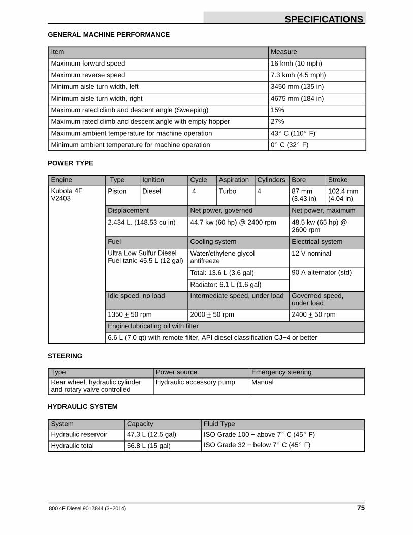
SPECIFICATIONS
75800 4F Diesel 9012844 (3−2014)
GENERAL MACHINE PERFORMANCE
Item Measure
Maximum forward speed 16 kmh (10 mph)
Maximum reverse speed 7.3 kmh (4.5 mph)
Minimum aisle turn width, left 3450 mm (135 in)
Minimum aisle turn width, right 4675 mm (184 in)
Maximum rated climb and descent angle (Sweeping) 15%
Maximum rated climb and descent angle with empty hopper 27%
Maximum ambient temperature for machine operation 43� C (110� F)
Minimum ambient temperature for machine operation 0� C (32� F)
POWER TYPE
Engine Type Ignition Cycle Aspiration Cylinders Bore Stroke
Kubota 4FV2403
Piston Diesel 4 Turbo 4 87 mm(3.43 in)
102.4 mm(4.04 in)
Displacement Net power, governed Net power, maximum
2.434 L. (148.53 cu in) 44.7 kw (60 hp) @ 2400 rpm 48.5 kw (65 hp) @ 2600 rpm
Fuel Cooling system Electrical system
Ultra Low Sulfur DieselFuel tank: 45.5 L (12 gal)
Water/ethylene glycol antifreeze
12 V nominal
Total: 13.6 L (3.6 gal) 90 A alternator (std)
Radiator: 6.1 L (1.6 gal)
Idle speed, no load Intermediate speed, under load Governed speed,under load
1350 + 50 rpm 2000 + 50 rpm 2400 + 50 rpm
Engine lubricating oil with filter
6.6 L (7.0 qt) with remote filter, API diesel classification CJ−4 or better
STEERING
Type Power source Emergency steeringRear wheel, hydraulic cylinderand rotary valve controlled
Hydraulic accessory pump Manual
HYDRAULIC SYSTEM
System Capacity Fluid Type
Hydraulic reservoir 47.3 L (12.5 gal) ISO Grade 100 − above 7� C (45� F)
ISO Grade 32 − below 7� C (45� F)Hydraulic total 56.8 L (15 gal)

SPECIFICATIONS
800 4F Diesel 9012844 (3−2014)76
BRAKING SYSTEM
Type Operation
Service brakes Hydraulic drum brakes (2), one per front wheel,foot brake master cylinder activated
Parking brake Utilize service brakes, cable actuated
TIRES
Location Type Size Pressure
Front (2) Pneumatic 6.5 x 23.5 in 690 − 758 kPa (100 − 110 psi)
Rear (1) Pneumatic 6.5 x 23.5 in 690 − 758 kPa (100 − 110 psi)
1875 mm (73.8 in)
1778 mm (70 in)
3048 mm (120 in)
TOP VIEW
SIDE VIEW FRONT VIEW
1911 mm (75.2 in)
08774
MACHINE DIMENSIONS

INDEX
77800 4F Diesel 9012844 (3−2014)
A
Adjusting engine speed (RPM), 17
Adjusting the Main Brush Taper, 63
Adjusting the Main Brush Width, 63
Air Conditioner FilterClean, 69Replace, 69
Air conditioning system (option)Belt, 45Switch, 20
Air control vents (option), 20
Air filter indicator, 50Reset, 50
Air intake hoses. Engine, 49
Aisle turn, 75
B
Battery, 58Charging system, Light, 13
BeltsAir Conditioning (option), 45Engine belt, 45
Boost sensor pressure hose, 49
Brake pedal, 11
Brake, parking, 68
BrakesService, 68System specifications, 76
Brakes and Tires, 68Rear Wheel, 68Tires, 68
Brush door seals, 66
Brush door skirts, 65
Brush Information, 21
BrushesAdjust side brush pattern, 64Checking / adjusting the main brush pattern, 62Checking side brush pattern, 64Door seals, 66Main brush adjustment knob, 12Rear skirts, 65Side brush adjustment knob, 12
Bypass valve, 70
C
Capacities, 74
Charging system light, 13
Check engine light, 14
Circuit breakers, 58
Clean / Replace Air Conditioner Filter, 69
Clogged dust filter light, 14
Clogged hydraulic filter light, 15
Control panelCharging System light, 13Check engine light, 14Clogged dust filter light, 14Clogged hydraulic filter light, 15Engine oil pressure, 13Engine water temperature light, 13Fuel level gauge, 15Hopper door light (option), 14Hopper temperature light, 13Main brush shut down light, 14Operating/hazard lights switch, 15Parking brake light, 17
ControlsAir conditioning switch (option), 20Air control vents (option), 20Charging system light, 13Check engine light, 14Clogged dust filter light, 14Clogged hydraulic filter light, 15Dome light switch, 19Engine Display Module, 17
Adjusting the engine speed (RPM), 17Engine oil pressure light, 13Engine water temperature light, 13Fan speed switch (option), 19Filter shaker switch, 16Fuel level gauge, 15Hazard light switch (option), 16Heater knob, 19Hopper temperature light, 13Horn button, 12Main brush adjustment knob, 12Operating/hazard lights switch, 15Parking brake light, 17Side brush adjustment knob, 12Steering wheel tilt handle, 12Vacuum fan switch, 16Windshield wiper switch (option), 19
Controls and Instruments, 8
Cooling System, 44Check the coolant level, 44Flush the radiator and the cooling system, 45
INDEX
800 4F Diesel 9012844 (3−2014)78
D
Debris hopper, 59
Dimensions, 74
Directional pedal, 11
Disengaging hopper support bar, 31
Dome light switch, 19
DoorsBrush, Seals, 66Hopper, Seals, 66
DPF (diesel particulate filter), 25, 48, 51
DPF (Diesel Particulate Filter) Alerts, 52
DPF (Diesel Particulate Filter) Regeneration, 51
DPF (Diesel Particulate Filter) Status Icons, 54
Draining the water / fuel separator, 46
Dust filter, 60Cleaning, 60
E
EDM (Engine Display Module), 17, 23, 51, 55, 57
EGR (exhaust gas recirculation) cooler, 48
Electrical system, circuit breakers, 58
Emptying the hopper, 28
Engaging hopper support bar, 30
Engine, 44Air filter assembly, 50Air filter indicator, 50Air intake hoses, 49Belt, 45Boost sensor pressure hose, 49Coolant temperature, Light, 13Cooling System, 44DPF (diesel particulate filter), 48DPF (Diesel Particulate Filter) Alerts, 52DPF (Diesel Particulate Filter) Regeneration, 51DPF (Diesel Particulate Filter) Status Icons, 54EGR (exhaust gas recirculation) cooler, 48Exhaust manifold, 48Fuel filter, 47Fuel Lines, 46Initiating a operator regeneration, 55Initiating a sweeping regeneration, 54Oil pressure, Light, 13Oil separator element, 47Oil separator hose, 47PCV (positive crankcase ventilation) valve, 47Priming the fuel system, 46Specifications, 75Turbo charger lubricant hose, 49Valve clearance, 49Water / fuel separator, 46
Engine air filter, Cleaning, 50
Engine air filter assembly, 50
Engine belt, 45
Engine Oil, 44
Engine oil pressure light, 13
Engine water temperature light, 13
Exhaust manifold, 48
F
Fan speed switch (option), 19
Filter shaker switch, 16
FiltersHopper dust, 60Hopper filter cleaning, 60Regenerative Filter System (RFS) (option), 35Replacing the hopper dust filter, 59
Front Wheel Bearings, 41
Fuel filter, 47
Fuel level gauge, 15
Fuel Lines, 46
G
Gauges, Fuel level, 15
Grease fittings, Rear Wheel Support Bearing, 41
H
Hazard light switch, 16
Heater knob, 19
Hopper, 59Clogged dust filter, Light, 14Cover seal, 67Disengaging hopper support bar, 31Door light (option), 14Door seals, 66Dust filter, 60Dust seal, 66Emptying the hopper, 28Engaging hopper support bar, 30Filter cleaning, 60Filter shaker, 16Lip skirts, 65Seals, 66Side skirt, 65Temperature, Light, 13Thermo Sentry, 13, 60Vacuum fan seal, 67

INDEX
79800 4F Diesel 9012844 (3−2014)
Hopper door seals, 66
Hopper seals, 66
Hopper side skirt, 65
Hopper temperature light, 13
Horn button, 12
Hour Meter, 15
How the Machine Works, 21
Hydraulic Cooler, 45Clean the fins, 45
Hydraulic fluid, 43
Hydraulic fluid reservoir, 42
Hydraulic Hoses, 43
Hydraulics, 42Check the hydraulic hoses, 43Clogged hydraulic filter light, 15Fluid, 43 − 45Hydraulic Hoses, 43Reservoir, 42System specifications, 75
I
Icons, DPF (Diesel Particulate Filter) Status, 54
Indicators, Hour Meter, 15
Initiating a parked regeneration, 55
Initiating a sweeping regeneration, 54
J
Jack points, 73
Jacking up the machine, 73
K
KnobsHeater, 19Main brush adjustment, 12Right side brush adjustment, 12
L
Levers, Steering wheel tilt handle, 12
LightsCharging system, 13Check engine, 14Clogged Dust filter, 14Clogged hydraulic filter light, 15Engine oil pressure, 13Engine water temperature, 13Hopper door (option), 14Hopper temperature, 13Main brush shut down, 14Operating/hazard lights switch, 15Parking brake, 17
Lubrication, 41Engine Oil, 44Front Wheel Bearings, 41main brush adjustment, 41Rear Wheel Support Bearing, 41Side brush pivot pins, 41
M
Machine components, 7
Machine dimensions, 76
Machine jacking, 73
Machine Operation, Pre-Operation Checklist, 22
Machine tie down location, 72
Machine Troubleshooting, 36
Main brushAdjustment, 12Checking / adjusting the brush pattern, 62Door seals, 66Door skirts, 65Rear skirts, 65Shut down light, 14
Main brush adjustment, lubrication, 41
Main brush adjustment knob, 12
Main Brushes, 61Adjusting the Taper, 63Adjusting the Width, 63Replacing or Rotating the Main Brushes, 61
Main Brushes, Adjusting the Taper, 63
Main Brushes, Adjusting the Width, 63
Main Brushes, Replacing or Rotating, 61
Maintenance, 37
Maintenance Chart, 37

INDEX
800 4F Diesel 9012844 (3−2014)80
O
Oil separator element, 47
Oil separator hose, 47
Operating/hazard lights switch, 15
Operation, 7
Operation of controls, 11
Operator seat, 18
Options, 32Air conditioning switch, 20Air control vents, 20Clogged dust filter light, 14Dome light switch, 19Fan speed switch, 19Hazard light switch, 16Heater knob, 19Hopper door light, 14Operating/hazard lights switch, 15Regenerative Filter System (RFS), 35Vacuum Wand, 32Windshield wiper switch, 19
P
Parking brake, adjustment, 68
Parking brake light, 17
Parking brake pedal, 11
PCV (positive crankcase ventilation) valve, 47
PedalsBrake pedal, 11Directional pedal, 11Parking brake pedal, 11
Pre-Operation Checklist, 22
Priming the fuel system, 46
Propelling Motor, 69Torque shaft nut, 69
Pushing or Towing the Machine, 70Bypass valve, 70
Pushing the Machine, 70
Pushing, Towing, and Transporting the Machine,70
Pushing or Towing the Machine, 70Transporting the Machine, 71
R
Radiator, 44, 45Check hoses and clamps, 44Clean core exterior, 45Replace hoses and clamps, 45
Rear skirts, 65
Rear tie down location, 72
Rear Wheel Support Bearing, 41
Rear Wheel, Torque, 68
Regenerative Filter System (RFS) (option), 35
Replacing or Rotating the Main Brushes, 61
Replacing the hopper dust filter, 59
Replacing the Side Brush, 64
Reset air filter indicator, 50
S
SafetyDisengaging hopper support bar, 31Engaging hopper support bar, 30Labels, 5Precautions, 3
Seals, 65Brush doors, 66Hopper, 66Hopper cover, 67Hopper door, 66Hopper vacuum fan, 67Hopper, dust, 66
Seat belts, 18
Seat support, 18
Seat, operator, adjustment, 18
Side brush, 64Adjust the pattern, 64Adjustment, 12Replacing the Side Brush, 64
Side brush down pressure knob, 12
Side brush pivot pins, lubrication, 41
Side Brush, Adjusting, 64
Side Brush, Replacing, 64
Side brush(es), Checking brush pattern, 64
Skirts, 65Brush door, 65Hopper Lip, 65Hopper side, 65Rear, 65
INDEX
81800 4F Diesel 9012844 (3−2014)
SpecificationsBraking system, 76Climb & descent angle, 75Dumping clearance height, 74Hydraulic system, 75Machine capacities, 74Machine dimensions, 74Machine performance, 75Power type, 75Steering, 75Tires, 76
Starting the machine, 23
Steering, specifications, 75
Steering wheel tilt handle, 12
Stop sweeping, 27
Storage Information, 73Storing the Machine, 73
Support, Seat, 18
Sweeping, 26
SwitchesAir conditioning (option), 20Dome light (options), 19Fan speed (option), 19Filter shaker, 16Hazard light (option), 16Operating/hazard lights, 15Vacuum fan, 16Windshield wiper (option), 19
Symbol definitions, 9
T
Thermo Sentry, 13, 60
Tie down location, 72Rear, 72
Tires, 68Pressure, 68Specifications, 76
Towing the Machine, 70
Transporting the Machine, 71
Travel speed, 75
Turbo charger lubricant hose, 49
Turning off the machine, 24
V
Vacuum fan switch, 16
Vacuum Wand, 32
Valve clearance, 49
Valves, 49Intake and exhaust, 49
Vents, air control, 20
W
Water / fuel separator, 46
Water / fuel seperator, Draining the water / fuelseparator, 46
Wheels, 68
While operating the machine, 25
Windshield wiper switch, 19

INDEX
800 4F Diesel 9012844 (3−2014)82