Operator’s Manual & SC7730 Parts List...
180
Operator’s Manual & Parts List SC7730 Sweeper/Scrubber Part No. 2-86-00321 revised 9/07 2003 American-Lincoln ® Printed in the USA Beginning with Serial No. 692198 READ THIS BOOK This book has important information for the use and safe operation of this machine. Failure to read this book prior to operating or attempting any service or maintenance procedure to your machine could result in injury to you or to other personnel. Damage to the machine or to other property could occur as well. You must have training in the operation of this machine before using it. If you or your operator (s) cannot read English, have this manual explained fully before attempting to operate this machine. All directions given in this book are as seen from the operator’s position at the rear of the machine.
Transcript of Operator’s Manual & SC7730 Parts List...
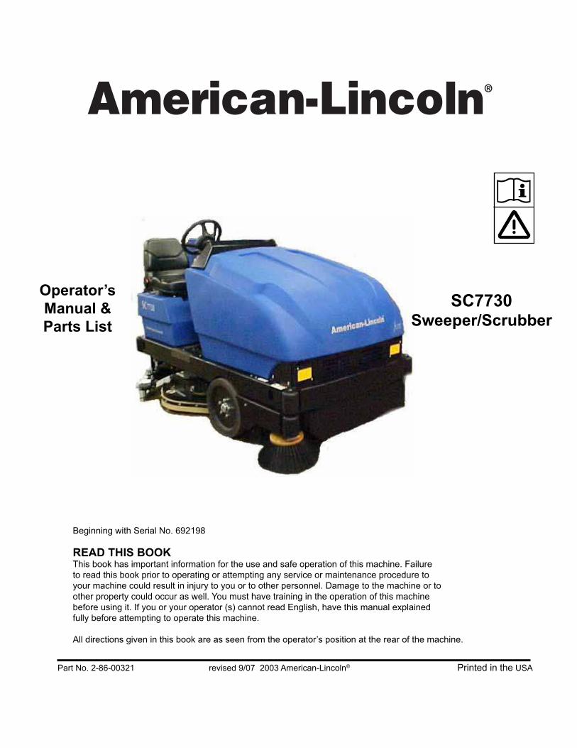
Operator’s
Manual &
Parts List
SC7730Sweeper/Scrubber
Part No. 2-86-00321 revised 9/07 2003 American-Lincoln® Printed in the USA
Beginning with Serial No. 692198
READ THIS BOOKThis book has important information for the use and safe operation of this machine. Failure
to read this book prior to operating or attempting any service or maintenance procedure to
your machine could result in injury to you or to other personnel. Damage to the machine or to
other property could occur as well. You must have training in the operation of this machine
before using it. If you or your operator (s) cannot read English, have this manual explained
fully before attempting to operate this machine.
All directions given in this book are as seen from the operator’s position at the rear of the machine.

1-2 AMERICAN-LINCOLN
SC7730
NOTES
AMERICAN-LINCOLN 1-3
SC7730
INDEX
C
CONTROLS 20-32
D
DECIMAL - METRIC CONVERSION TABLE 5
DISCLAIMER 4
H
HARDWARE ABREVIATIONS 6
HYDRAULIC TORQUE REQUIREMENTS 8
M
MACHINE PREPARATION 17, 18, 19
MAINTENANCE 44-58
O
OPERATING INSTRUCTIONS 33-43
ORDERING PARTS 10
S
SAFETY PRECAUTIONS 11, 12
SPECIFICATIONS 14, 15, 16
STANDARD HARDWARE & TORQUE VALUES 7
SYMBOLS 9
T
TROUBLESHOOTING 59, 60

1-4 AMERICAN-LINCOLN
SC7730
DISCLAIMER
DISCLAIMER
The information contained in this manual is believed correct at the time of publication. American Lincoln
assumes no responsibility or liability for unauthorized changes made to this manual or pages removed, causing
indirect or consequential damages resulting from the use of the information appearing herein.
WARNING!
In the event that machinery or controls described herein are modified in any way, or in the event that such
machinery or controls are not maintained in a proper manner, the instructional material contained herein may
be rendered inaccurate. The information contained herein is to be used only by persons knowledgeable in the
operation of machinery such as that described herein, or other persons being directly supervised by such
knowledgeable persons.
No portion of this manual may be reproduced without the express written consent of:
AMERICAN LINCOLN
Product Engineering
1100 Haskins Road
Bowling Green, OH, 43402
(419) 352-7511 Fax: (419) 373-4284
Copyright 2003 American Lincoln. All rights reserved.
Printed in USA March 2003

AMERICAN-LINCOLN 1-5
SC7730
FRACTION FRACTIONDECIMAL DECIMALMILLIMETER MILLIMETER
C-2001/9907
DECIMAL - METRIC CONVERSION TABLE

1-6 AMERICAN-LINCOLN
SC7730
ABBREVIATIONS-SCREWS
ADJ = Adjusting Screw
ADJ.SP = Adjusting Plunger Screw
BHM = Binding Head Machine Screw
BHS = Button Head Socket Screw
CAPT.SL = Captivated Slotted Screw
CAPT.WG = Captivated Wing Screw
FHM = Flat Head Machine Screw
FIL.HM = Filister Head Machine Screw
HHC = Hexagon Head Cap Screw
HHM = Hexagon Head Machine Screw
HIHD = ½ High Head Screw
HSHC = Hexagon Socket Head Cap Screw
HSFHC = Hexagon Socket Flat Head Cap Screw
KNH = Knurled Head Screw
MHHC = Metric Hexagon Head Cap Screw
PHM = Pan Head Machine Screw
RHD = Round Head Drive Screw
RHM = Round Head Machine Screw
RHW = Round Head Wood Screw
SHC = Shiny Crown Cap Screw
SHTB = Shoulder Thumb Screw
SQ = Square Head Screw
TB = Thumb Screw
THM = Truss Head Machine Screw
WELD = Weld Stud
WG = Wing Screw
ABREVIATIONS-SETSCREWS
HS = Hexagon Socket Setscrew
S = Slotted Setscrew
SH = Square Head Setscrew
KCP = Knurled Cup Point Setscrew
CP = Cup Point Setscrew
OP = Oval Point Setscrew
FDP = Full Dog Point Setscrew
HDP = Half Dog Point Setscrew
FP = Flat Point Setscrew
COP = Cone Point Setscrew
HARDWARE ABREVIATIONS

AMERICAN-LINCOLN 1-7
SC7730
SAE - Grade 5 SAE - Grade 8
ScrewSize
Grade5
Plated
Grade8
Plated
410HStainless
BrassTypeF & T& BT
TypeB, AB
*6
*8
*10
*1/4
5/16
3/8
7/16
1/2
9/16
5/8
3/4
7/8
1
14
27
39
86
15
28
44
68
98
135
239
387
579
15
28
43
108
17
31
49
76
110
153
267
-
-
-
-
-
130
22
40
63
95
138
191
338
545
818
-
-
-
151
24
44
70
108
155
216
378
-
-
18
33
47
114
19
34
55
85
-
-
-
-
-
20
35
54
132
22
39
62
95
-
-
-
-
-
5
9
13
32
6
10
16
-
-
-
-
-
-
20
37
49
120
-
-
-
-
-
-
-
-
-
23
41
64
156
-
-
-
-
-
-
-
-
-
21
34
49
120
-
-
-
-
-
-
-
-
-
CC C CF F F F
C = Coarse ThreadF = Fine Thread* = Torque values for #6 through 1/4 are lb./in. All others are lb./ft.
NOTE
Decrease the torque by 20% when using thread lubricantThe torque tolerance is ± on torque values.
C2000/9905
STANDARD HARDWARE & TORQUE VALUES

1-8 AMERICAN-LINCOLN
SC7730
02
SAEDashSize
-3-4-5-6-8
-10-12-14-16-20-24
ThreadSizeInch
3/8-247-16-20
½-209/16-183/4-167/8-14
1 1/16-121 3/16-121 5/16-121 5/8-121 7/8-12
Str. Fittingor Locknu
TorqueLB-FT8-10
14-1618-2024-2550-6072-80
125-135160-180200-220210-280270-360
ThreadSizeInch
*9/16-18
*11/16-1613/16-16
1-141 3/16-121 3/16-121 7/16-121 11/16-12
2-12
Swivel NutTorque
LB-FT*
10-12*
18-2032-3546-5065-7065-70
92-100125-140150-165
Nominal O-Ring Face Seal End SAE O-Ring Boss End
HYDRAULIC TORQUE REQUIREMENTSRefer to the following chart for torque values on all hydraulic hoses & fittings
NOTEParts must be lightly oiled with hydraulic fluid
-Ring face-seal-type end not defined for this tube size
HYDRAULIC TORQUE REQUIREMENTS

AMERICAN-LINCOLN 1-9
SC7730
Scrub Brush Down Heavy Pressure
Squeegee Down & Vacuum On
Squeegee Up & Vacuum On
Solution Tank Low
Solution Flow Control
Throttle
Read Machine Manual
No gas or combustibles in tank
Keep Away From Flames/
Wear Eye Protection
Electrical Hazard
Stay Clear
Moving Fan Blade
Pinch Point/Crush Hazard
Cover or Hopper Could Close/
Turn Key Off/Lock Wheel
WARNING! / ATTENTION!
Squeegee Up & Vacuum Off
Battery Charger
Choke
Fan On
Filter Shaker On
Forward/Reverse
Headlights
Hopper Dump
Hopper Return
Horn
Main Broom & Side Broom Up
Main Broom & Side Broom Down
No Step
Off
On
Power
Recovery Tank High
Scrub Brush Down & On
Scrub Brush Up and Off
THESE SYMBOLS IDENTIFY CONTROLS, DISPLAYS/FEATURES, AND SAFETY SYMBOLS ON THE MACHINE.
Before Operating or Servicing
NO Smoking
Engage Support
Before Leaving Seat
SYMBOLS
MACHINE CATALOG NUMBER
505-320 SC7730 (40”) SWEEPER/SCRUBBER505-321 SC7730 (46”) SWEEPER/SCRUBBER505-322 SC7730 (40”) SWEEPER/SCRUBBER W/ DUST CONTROL505-323 SC7730 (46”) SWEEPER/SCRUBBER W/ DUST CONTROL
MACHINE CATALOG NUMBER
505-320 SC7730 (40”) SWEEPER/SCRUBBER505-321 SC7730 (46”) SWEEPER/SCRUBBER505-322 SC7730 (40”) SWEEPER/SCRUBBER W/ DUST CONTROL505-323 SC7730 (46”) SWEEPER/SCRUBBER W/ DUST CONTROL
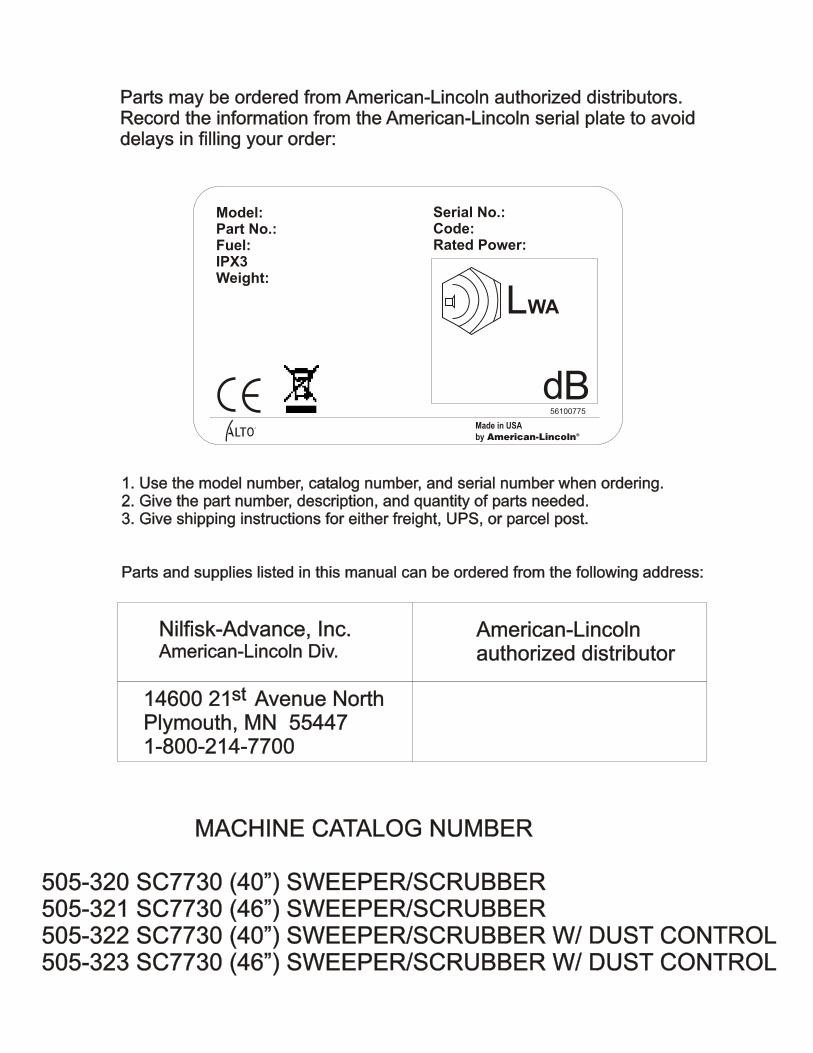
Parts may be ordered from American-Lincoln authorized distributors. Record the information from the American-Lincoln serial plate to avoiddelays in filling your order:
Parts may be ordered from American-Lincoln authorized distributors. Record the information from the American-Lincoln serial plate to avoiddelays in filling your order:
1. Use the model number, catalog number, and serial number when ordering.2. Give the part number, description, and quantity of parts needed.3. Give shipping instructions for either freight, UPS, or parcel post.
Parts and supplies listed in this manual can be ordered from the following address:
1. Use the model number, catalog number, and serial number when ordering.2. Give the part number, description, and quantity of parts needed.3. Give shipping instructions for either freight, UPS, or parcel post.
Parts and supplies listed in this manual can be ordered from the following address:
Nilfisk-Advance, Inc.American-Lincoln Div.Nilfisk-Advance, Inc.American-Lincoln Div.
American-Lincolnauthorized distributorAmerican-Lincolnauthorized distributor
14600 21 Avenue NorthPlymouth, MN 554471-800-214-7700
14600 21 Avenue NorthPlymouth, MN 554471-800-214-7700
stst
Model:Part No.:Fuel:IPX3Weight:
Serial No.:Code:Rated Power:
B
LWA
R
56100775
Made in USA
by American-Lincoln®

AMERICAN-LINCOLN 1-11
SC7730
SAFETY PRECAUTIONS
ELECTRICAL HAZARD - Shocks cancause serious personal injury
Disconnect battery before workingin this area
Repairs must be performed byauthorized personnel only
WARNING
The following safety labels are mounted on the machinein the locations indicated. If the labels become damagedor illegible replace with identical label.
Scrub deck presents hazardfor crushing, entanglement,
friction and abrasion
Dust Control Motor presentshazard for shearing and cutting
Broom Chamber presentshazard for entanglement,
friction and abrasion

1-12 AMERICAN-LINCOLN
SC7730
HAZARD SERIOUSNESS LEVEL
Signal words (DANGER, WARNING and CAUTION) are used to identify levels of hazard seriousness. The
degree of severity is based on the likely consequences of human interaction with the hazard.
DANGER
To warn of immediate hazards which will result in severe personal injury or death.
WARNING
To warn of hazard or unsafe practices which could result in severe personal injury.
CAUTION
To warn of hazards or unsafe practices which could result in minor personal injury.
ATTENTION
To warn of unsafe practices which could result in extensive equipment damage.
NOTE
To give important information or to warn of unsafe practices which could result in equipment damage.
For the safe operation of this machine, read and understand all WARNINGS, CAUTIONS AND NOTES.
PERSONAL SAFETY
• Read this manual carefully. The following information signals potentially dangerous conditions to the
operator or equipment. Know when these conditions can exist then take necessary steps to train
machine operating personnel.
• Dress appropriately; loose clothing, jewelry and other accessories may get caught in the machine and
cause physical injury.
• Wear OSHA/NIOSH protective eye wear or prescription glasses to protect eyes.
• Wear appropriate gloves when filling and/or draining tanks.
• Before operating machine, test brake mechanism, lights and back up alarm (if applicable).
• Observe maintenance schedule guidelines to assume optimal safe operation of the machine.
• Be aware of pinch pints that exist on the machine.
• Do not operate machine if you are tired, upset, ill on medication or intoxicated.
• Be completely aware of your surroundings. STOP, LOOK, and LISTEN for other employees walking in
or around your cleaning area.
MACHINE SAFETY
• Operator must be properly trained to operate machine.
• Read this manual before operating machine
• Familiarize yourself with all components and safety features.
• Do not operate machine unless it is completely assembled.
• Do not use machine other than intended use.
• Report damages or maintenance problem immediately. Do not use machine until it has been repaired.
• Repairs should be done by authorized personnel.
• For storage, keep machine in a building.
• This machine is not at tow truck and should not be used for towing.
• Do not use this machine as a step or furniture.
• Do not operate machine on public highways, gravel, sand, grass and other unsafe surfaces.
SAFETY PRECAUTIONS

AMERICAN-LINCOLN 1-13
SC7730
• Be careful when operating the machine on a ramp or incline. Do not operate machine on incline greater
than 8° or longer than 100’. Always move slowly on a ramp. Do not turn this machine on a ramp.
• Do not stop and leave this machine on a ramp. Always stop the machine on a level surface, put the
power switch in the on position.
• To prevent injury, and damage to the machine, do not lift the machine or move it to an edge of a stair or
loading dock.
• Turn off machine when unattended, filling, fueling or doing maintenance on machine (if applicable).
• Do not operate machine near flammable materials, fire or explosion may occur.
• Solution or recovery tank should not be filled with fuel or chemicals.
• Read label on cleaning solutions to verify it is safe for machine.
• Use a cleaning concentrate recommended by the chemical manufacturer.
• Water solutions or cleaning materials used can leave wet areas on floor surfaces causing dangerous
conditions for the operator or other persons. Always put CAUTION signs near area you are cleaning.
• Use care when reversing machine.
• Always empty the solution tank and recovery tank before doing maintenance.
• Unplug the battery first to prevent possible injury when servicing a machine.
• Lead acid batteries generate gases, which can cause an explosion. Keep sparks and flames away
from batteries. NO SMOKING. Charge batteries only in area with good ventilation.
• Always wear eye protection and protective clothing when working near batteries. Remove all jewelry.
• Do not put tools or other metal objects across the battery terminals, or the tops of batteries.
• Keep electrical parts of the machine dry.
• Make sure that all labels, decals, warnings, cautions and instructions are fastened to the machine.
• Get new labels and decals from American-Lincoln.
SAFETY PRECAUTIONS

1-14 AMERICAN-LINCOLN
SC7730
CLEANING PATH
Scrubbing 40 in. (101 cm)
46 in. (117 cm)
Sweeping 46in. (117 cm)
Edge Cleaning 6 in.(15 cm) Right Side 46in. 117 cm) only
TRANSPORT SPEED 0-4.6 MPH (0 - 7.4kph)
OPERATING SPEED 0-2.7 MPH (0 - 4.3kph)
POWER SUPPLY (1) 36 Volt Wet Battery, 720 AH
For machine to operate properly, voltage reading should fall within 32-40 vdc.
CHARGER 240 Vac, 3-phase, 60 Hz, 36 Vdc, 150 A
STEERING Rack & Pinion 90°-90° Hyd. Assist
Adjustable Steering Column
TURNING RADIUS
Left 59 in. (150 cm)
Right 59 in. (150 cm)
Aisle “U” Turn 87 in. (221 cm)
DIMENSIONS
Length 87 in. (221 cm)
Width 46 in. (116.8 cm)
Height 52 in. (132 cm)
Height w/Overhead Guard 79 in. (200.6 cm)Wheel Base 37.6 in. (95.5 cm)
WEIGHT
Standard Machine (Battery) 1700 lbs. (765 kg.) without battery
720 Ah battery 1990 lbs. (896 kg)
TIRES
Front (Battery) Solid Urethane Two (2)16 in (41cm) x 3.75 in (8.26 cm)
Rear (Battery) Solid Rubber One (1)16 in (41 cm) x 4.00 in (10.16cm)
RAMP CLIMBING
Transporting 8°
MAIN BROOM
One piece plastic core disposable type. Broom position can be set to “restricted down” or
“free floating”.
Length 36 in (91.4 cm)
Diameter 10 inches (25.4 cm)
Optional Bristle Type Nylon (High density)
Proex
Nylon Eight (8) Row
SIDE BROOM
Side Broom Size 16 inches (40.6 cm) Diameter
SPECIFICATIONS

AMERICAN-LINCOLN 1-15
SC7730
SPECIFICATIONS
INSTRUMENTS AND CONTROLS
Main/Side Broom Switch Key Switch
Headlight/Taillight Switch (option) Hour Meter
Squeegee Switch Recovery High Light
3 Position Scrub Deck Switch Dust Control Switch (with certain models)
Horn Button Solution Low Light
Solution Control Knob ESP (Option)
Hopper Up/Down Switch Filter Shaker Switch
Hopper Open Light Squeegee and Vacuum Wand (Option)
SCRUBBING SYSTEM
Brush Size-46” (116.84 cm) Three (3) 16” (40.6cm) Diameter
Brush Size-40” (101.4 cm) Two (2) 20” (51cm) Diameter
Brush Lift Hydraulic Actuator
Scrub Pressure
Normal 140 lbs.
Heavy 200 lbs.
SQUEEGEE
Rear Accu-Trac™ 46 in(116.8 cm) Swing, break away,
w/no tool squeegee replacement
Side 26 in (66 cm) Easy Change
TANKS
Solution Tank 55 Gallons (208 liter)Polyethylene
Recovery Tank 55 Gallons (208liter)Polyethylene
Solution Metering Variable to 3.0 GPM (11.4 lpm)Drain Hose 48 in (122 cm)
Clean Out Port 5.7 in (14.5 cm) heavy debris
HOPPER
Capacity 2.5 cu.ft.(71liter)
DUMP AND LIFT
Dump Height 14 in (35.6 cm.)
SYSTEM FLUID CAPACITIES
Hydraulic System 4.7 Gallons (17.79 Liters)
OPTIONAL EQUIPMENT
Back-Up Alarm Headlight/Taillights
ESP System Fire Extinguisher
Overhead Guard Squeegee Wand
Spray and Vac Wand Black Nylon Brush
Linatex Squeegee Polypropylene Brush
720 Amp Hour Battery Supergrit Brush
Strobe Light (Amber) Clean Grit Brush
Strobe Light (Amber) W/ OH Guard Arm Rest (RH only)
Polyethelyne Panel Filter Seat Belt
Smart Cart (Battery Roll Out Cart)

1-16 AMERICAN-LINCOLN
SC7730
SPECIFICATIONS

AMERICAN-LINCOLN 1-17
SC7730
MACHINE PREPARATION
Your SC7730 battery machine has been shipped complete, but do not attempt to operate without reading the
following instructions:
UNPACKING AND ASSEMBLING MACHINE
The SC7730 is shipped on a pallet and held in place with wooden block to stop the machine from moving.
1) Remove wooden blocks holding machine in place.
2) Position a 11° and 48” ramp on base of pallet.
11 DEGREE
48 INCHES
Fig 2
Fig 1
1-18 AMERICAN-LINCOLN
SC7730
MACHINE PREPARATION
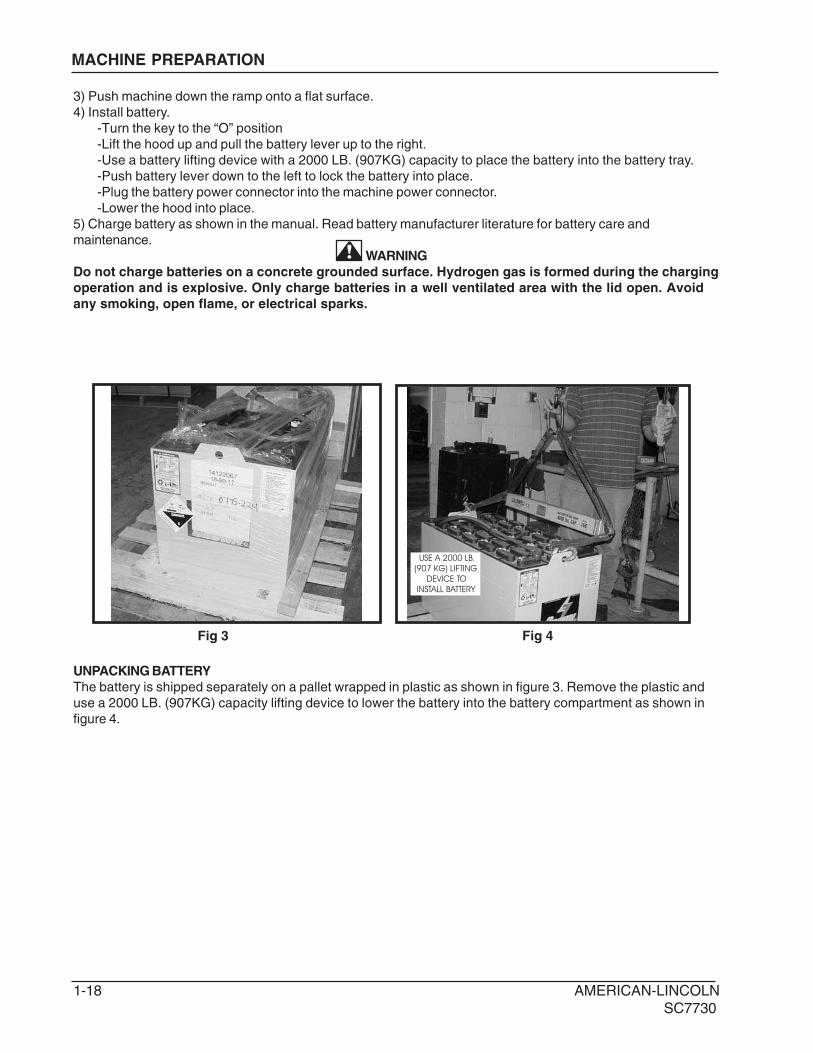
UNPACKING BATTERY
The battery is shipped separately on a pallet wrapped in plastic as shown in figure 3. Remove the plastic and
use a 2000 LB. (907KG) capacity lifting device to lower the battery into the battery compartment as shown in
figure 4.
USE A 2000 LB.
(907 KG) LIFTING
DEVICE TO
INSTALL BATTERY
Fig 3 Fig 4
3) Push machine down the ramp onto a flat surface.
4) Install battery.
-Turn the key to the “O” position
-Lift the hood up and pull the battery lever up to the right.
-Use a battery lifting device with a 2000 LB. (907KG) capacity to place the battery into the battery tray.
-Push battery lever down to the left to lock the battery into place.
-Plug the battery power connector into the machine power connector.
-Lower the hood into place.
5) Charge battery as shown in the manual. Read battery manufacturer literature for battery care and
maintenance.
WARNING
Do not charge batteries on a concrete grounded surface. Hydrogen gas is formed during the charging
operation and is explosive. Only charge batteries in a well ventilated area with the lid open. Avoid
any smoking, open flame, or electrical sparks.

AMERICAN-LINCOLN 1-19
SC7730
MACHINE PREPARATION
BATTERY LEVER
MACHINE POWER CONNECTOR
BATTERY POWER CONNECTOR
CONNECTING BATTERY
LOCK BATTERY IN PLACE WITH LEVER
BATTERY INSTALLATION
1. Lift the machine front cover.
2. Rotate the battery lever to the right.
3. Lower the battery into place using a 2000 LB. (907 KG) capacity lifting device.
4. Rotate the battery lever to the left to lock the battery into place.
5. Connect battery wires according to manufacturer’s direction.
6. Connect the battery power connector to the machine power connector.
7. Lower the machine front cover into place.
WARNING
Do not leave charged batteries on concrete surface, they will discharge.
Fig 5
Fig 7 Fig 8
Fig 6
1-20 AMERICAN-LINCOLN
SC7730
CONTROLS
3
7 8 9 10
11
12 13
14
15
1617
18
19
6
541
2
20
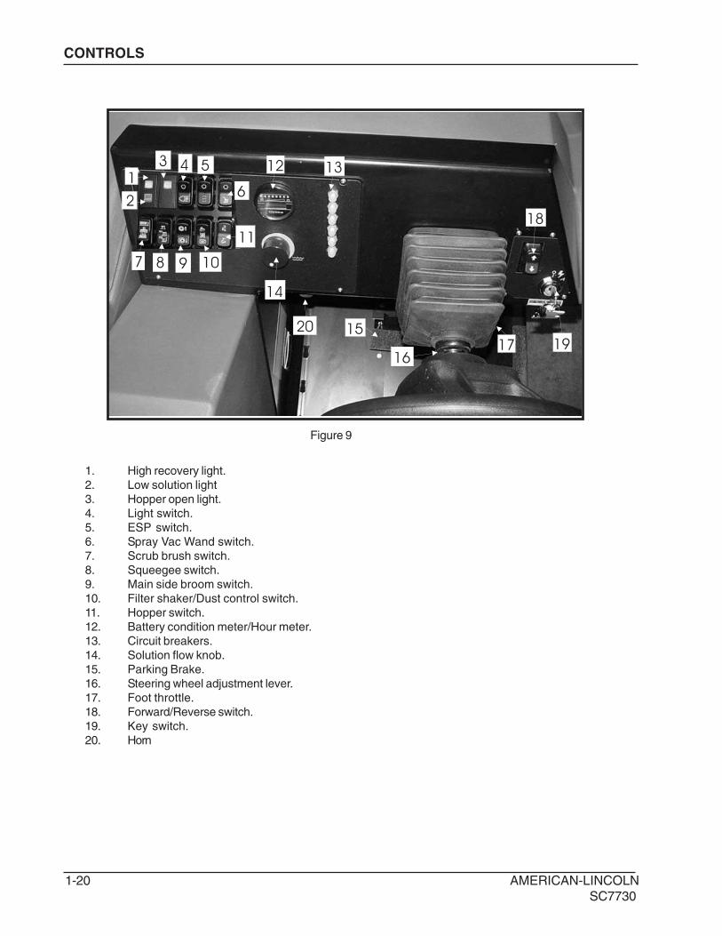
1. High recovery light.
2. Low solution light
3. Hopper open light.
4. Light switch.
5. ESP switch.
6. Spray Vac Wand switch.
7. Scrub brush switch.
8. Squeegee switch.
9. Main side broom switch.
10. Filter shaker/Dust control switch.
11. Hopper switch.
12. Battery condition meter/Hour meter.
13. Circuit breakers.
14. Solution flow knob.
15. Parking Brake.
16. Steering wheel adjustment lever.
17. Foot throttle.
18. Forward/Reverse switch.
19. Key switch.
20. Horn
Figure 9

AMERICAN-LINCOLN 1-21
SC7730
KEY SWITCH
The keyed ignition switch is located on the ioperator’s console as shown in figure 10.
The “OFF” position (O position) will shut off the machine. The IGN/ON position (I position) provides power to all
machine systems and accessories.
KEY SWITCH
CONTROLS
Figure 10
Figure 11
FORWARD
REVERSE
SWITCH
FORWARD / REVERSE SWITCH
The forward/reverse switch is located on the operator’s console as shown in figure 11. Pressing the upper half
of the forward/reverse switch will result in the machine moving forward when the foot throttle is depressed.
Pressing lower half of the forward/reverse lever switch will result in the machine moving backward when the foot
throttle is depressed.

1-22 AMERICAN-LINCOLN
SC7730
NOTE
To reengage, the key must be returned to the “OFF” position.
HOUR METER
The hour meter is located on the instrument panel as shown in figure 13. Tthe diplay will show the total hours
the machine has been in operation. The meter is activated when the key switch is placed in the ignition position.
The meter can be used to determine when maintenance should be done on the machine.
HOUR METER
Figure 12
Figure 13
CONTROLS
BATTERY CONDITION METER
BATTERY CONDITION METER
The battery condition meter is located on the instrument panel as shown in figure 12. The condition meter
indicates the level of charge in the batteries. The batteries are sufficiently charged when all of the LED’s are
illuminated amber as shown on the ramp illustration. Charge the batteries when one red LED is illuminated on
the left at the bottom of the ramp diagram and the scrub brushes stop. Do not operate the machine.

AMERICAN-LINCOLN 1-23
SC7730
CONTROLS
Figure 14
LIGHT
HEADLIGHT/TAILIGHT SWITCH (Optional)
The light switch is located on the instrument panel as shown in figure 14. By pressing on the lower half of the
switch the headlights and taillights will be activated. Pressing the upper half of the switch will turn off the lights.
HOPPER INDICATOR LIGHT
HOPPER OPEN LIGHT WARNING
The hopper open light switch is located on the instrument panel as shown in figure 15. When the hopper is
open, the light is illuminated the broom and the dust control fan will stop.
Figure 15

1-24 AMERICAN-LINCOLN
SC7730
FILTER SHAKER
DUST CONTROL ONDUST CONTROL OFF
CONTROLS
Figure 16
Figure 17
FILTER SHAKER SWITCH (Only models with dust control)
The filter shaker switch is located on the instrument panel as shown in figure 16. By pressing and holding in
the upper half of the switch, it will activate the filter shaker motors for 20 to 30 seconds. Releasing the switch,
returns to the off position.
The dust control fan will stop when the filter shaker has been activated. The filter shaker will only operate with
the hopper in the “DOWN” position.
DUST CONTROL SWITCH
The dust control switch is located on the instrument panel as shown in figure 17. To turn on the dust control
system for normal sweeping, press the lower half of the switch.
WARNING
Turn the dust control switch to the center “OFF” position while wet sweeping. Water will damage the
filter and cause premature filter failure.
AMERICAN-LINCOLN 1-25
SC7730
SCRUB BRUSHES
SQUEEGEE
CONTROLS
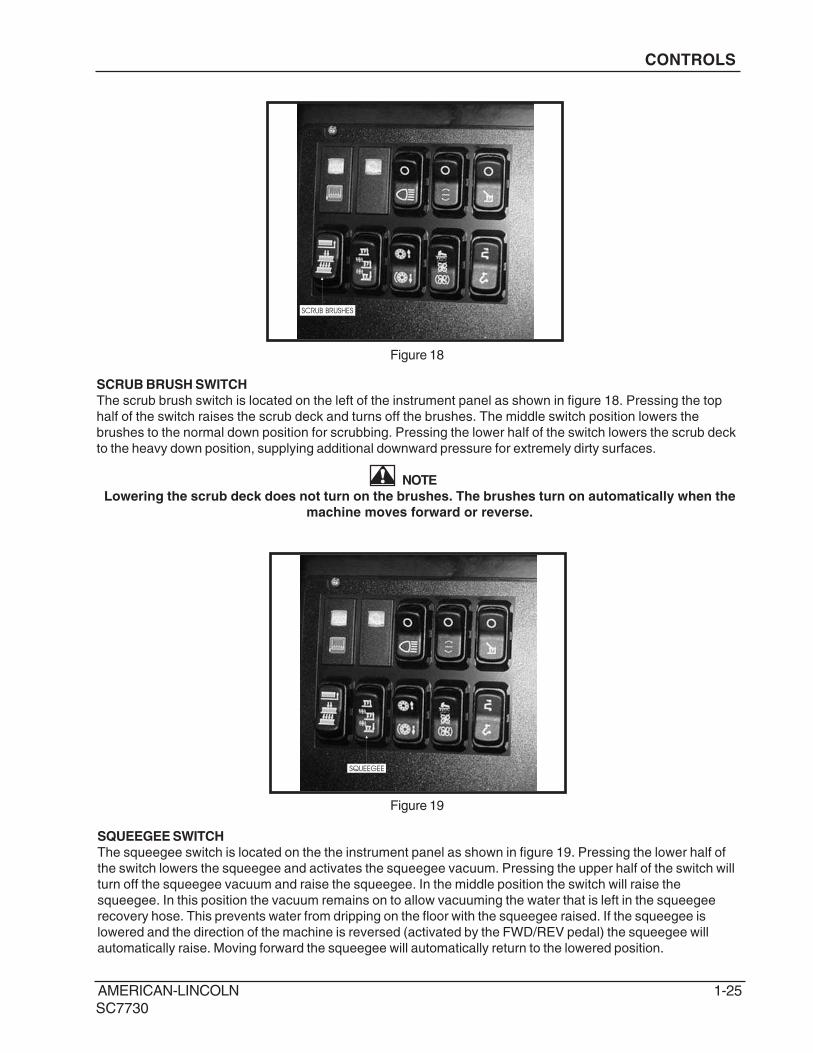
Figure 18
Figure 19
SCRUB BRUSH SWITCH
The scrub brush switch is located on the left of the instrument panel as shown in figure 18. Pressing the top
half of the switch raises the scrub deck and turns off the brushes. The middle switch position lowers the
brushes to the normal down position for scrubbing. Pressing the lower half of the switch lowers the scrub deck
to the heavy down position, supplying additional downward pressure for extremely dirty surfaces.
NOTE
Lowering the scrub deck does not turn on the brushes. The brushes turn on automatically when the
machine moves forward or reverse.
SQUEEGEE SWITCH
The squeegee switch is located on the the instrument panel as shown in figure 19. Pressing the lower half of
the switch lowers the squeegee and activates the squeegee vacuum. Pressing the upper half of the switch will
turn off the squeegee vacuum and raise the squeegee. In the middle position the switch will raise the
squeegee. In this position the vacuum remains on to allow vacuuming the water that is left in the squeegee
recovery hose. This prevents water from dripping on the floor with the squeegee raised. If the squeegee is
lowered and the direction of the machine is reversed (activated by the FWD/REV pedal) the squeegee will
automatically raise. Moving forward the squeegee will automatically return to the lowered position.

1-26 AMERICAN-LINCOLN
SC7730
LOW SOLUTION LIGHT
HIGH RECOVERY LIGHT
CONTROLS
Figure 20
Figure 21
LOW SOLUTION LIGHT
The low solution warning light is located on the instrument panel as shown in figure 20. The low solution
warning light illuminates when the solution tank is empty, marking the end of the scrubbing cycle.
HIGH RECOVERY LIGHT
The high recovery warning light is located on the instrument panel as shown in figure 21. The light will illuminate
approximately 5 minutes before the recovery tank is full, giving ample time to complete the scrubbing cycle,
before the mechanical float shuts off the vacuum to the recovery tank.
AMERICAN-LINCOLN 1-27
SC7730
HOPPER
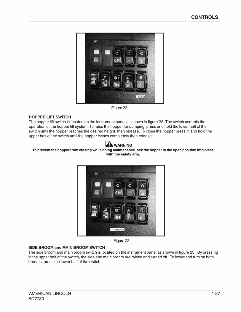
HOPPER LIFT SWITCH
The hopper lift switch is located on the instrument panel as shown in figure 22. The switch controls the
operation of the hopper lift system. To raise the hopper for dumping, press and hold the lower half of the
switch until the hopper reaches the desired height, then release. To close the hopper press in and hold the
upper half of the switch until the hopper closes completely then release.
WARNINGTo prevent the hopper from closing while doing maintenance lock the hopper in the open position into place
with the safety arm.
Figure 22
CONTROLS
MAIN BROOM
Figure 23
SIDE BROOM and MAIN BROOM SWITCH
The side broom and main broom switch is located on the instrument panel as shown in figure 23. By pressing
in the upper half of the switch, the side and main broom are raised and turned off. To lower and turn on both
brooms, press the lower half of the switch.

1-28 AMERICAN-LINCOLN
SC7730
SPRAY VACCUM
ESP SWITCH (Optional)
The ESP switch is located on the instrument panel as shown in figure 24. The ESP switch transfers water from
the recovery tank through a filter and into the solution tank. When the switch is in the down position the pump
will operate when the high recovery light is illuminated. Clean the recovery tank when the tank is emptied.
NOTEDo not place clean water in the recovery tank when using ESP option, the solution tank could become overfilled
during operation.
ESP
Figure 24
Figure 25
CONTROLS
SPRAY AND VAC WAND SWITCH (Optional)
The spray and vac wand switch is located on the instrument panel as shown in figure 24. Pressing the bottom
half of switch turns on the vacuum motor and the solution pump. Pressing the top half of the switch turns the
vacuum motor and solution pump off.
AMERICAN-LINCOLN 1-29
SC7730
SIDE BROOM ADJUSTMENT KNOB
MAIN BROOM ADJUSTMENT KNOB
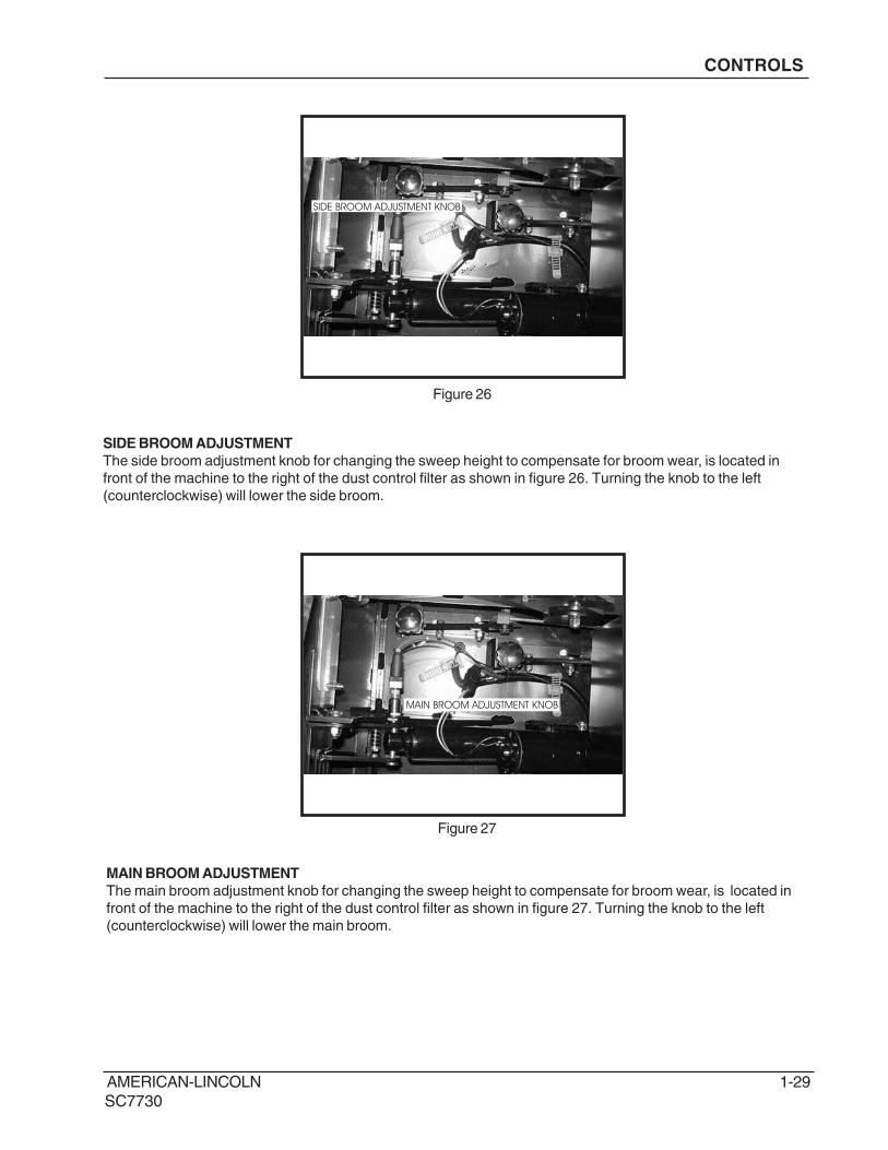
MAIN BROOM ADJUSTMENT
The main broom adjustment knob for changing the sweep height to compensate for broom wear, is located in
front of the machine to the right of the dust control filter as shown in figure 27. Turning the knob to the left
(counterclockwise) will lower the main broom.
CONTROLS
Figure 27
Figure 26
SIDE BROOM ADJUSTMENT
The side broom adjustment knob for changing the sweep height to compensate for broom wear, is located in
front of the machine to the right of the dust control filter as shown in figure 26. Turning the knob to the left
(counterclockwise) will lower the side broom.
1-30 AMERICAN-LINCOLN
SC7730
CONTROLS
Figure 28
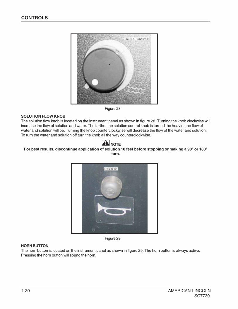
SOLUTION FLOW KNOB
SOLUTION FLOW KNOB
The solution flow knob is located on the instrument panel as shown in figure 28. Turning the knob clockwise will
increase the flow of solution and water. The farther the solution control knob is turned the heavier the flow of
water and solution will be. Turning the knob counterclockwise will decrease the flow of the water and solution.
To turn the water and solution off turn the knob all the way counterclockwise.
NOTE
For best results, discontinue application of solution 10 feet before stopping or making a 90° or 180°
turn.
HORN BUTTON
HORN BUTTON
The horn button is located on the instrument panel as shown in figure 29. The horn button is always active.
Pressing the horn button will sound the horn.
Figure 29

AMERICAN-LINCOLN 1-31
SC7730
FOOT THROTTLE
FOOT THROTTLE
The foot throttle is located to the right of the brake pedal on the floor of the operator’s compartment as shown in
figure 30. This pedal controls the machine travel speed. Press the forward/reverse switch to chose the travel
direction, and then press down on the foot throttle to move set the machine in motion. Increase the foot
pressure to increase the travel speed.
Figure 30
BRAKE PEDAL
PEDAL LOCK
PARKING BRAKE
The parking brake is located on the floor of the machine left of the foot throttle as shown in figure 31. To set the
parking brake, press down on the foot pedal and the press down the lock. To unlock the parking brake, push
down on the upper portion of the foor pedal and release.
Figure 31
CONTROLS

1-32 AMERICAN-LINCOLN
SC7730
CONTROLS
SEAT ADJUSTMENT LEVER
SEAT POSITION ADJUSTMENT
The seat position adjustment lever is located on the front of the seat to the left as seen in figure 34. The lever is
spring loaded to the lock position. To adjust the seat, push the lever to the left and move the seat to the desired
position and then release the lever to lock the seat into place.
Figure 34
SAFETY FEATURES
SEAT SAFETY SWITCH - Machine will not move and parking brake will set if this switch is not activated.
SPEED INTERLOCK - Maximum machine speed will be reduced while scrub brushes are in use.
BRUSHES OFF IN NEUTRAL - Scrub brushes automatically disengage when machine is idle.
AUTOMATIC RECOVERY VACUUM SHUT-OFF - Vacuum fans will shut down when recovery tank is full.
AMERICAN-LINCOLN 1-33
SC7730
OPERATING INSTRUCTIONS
NOTEBefore starting the engine, perform the pre-start checklist.Before starting the engine, perform the pre-start
checklist.
PRE-START CHECKLIST
Check hydraulic fluid level.
Check all systems for leaks.
Check brakes and controls for proper operation.
Check broom patterns.
Check hydraulic fluid level.
Check hydraulic connections for leaks.
Check brakes and controls for proper operation.
Check broom pattern.
Check to ensure that all covers, panels and access doors are securely closed.
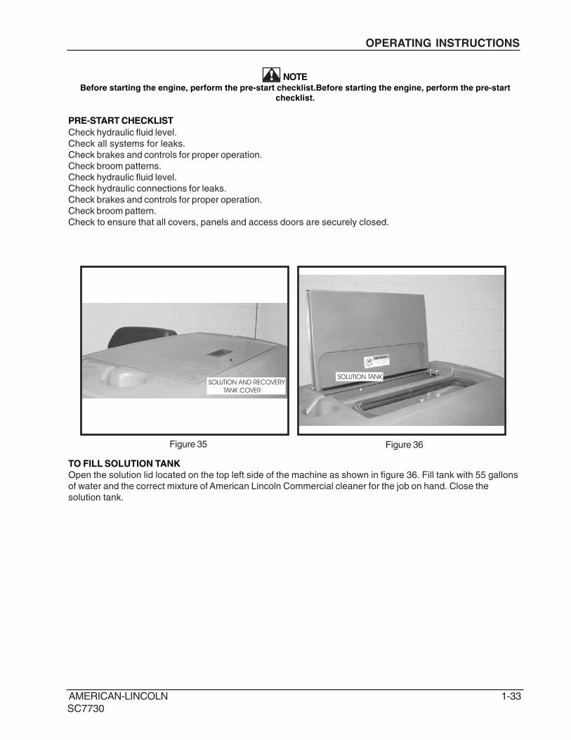
SOLUTION TANK
Figure 35
TO FILL SOLUTION TANK
Open the solution lid located on the top left side of the machine as shown in figure 36. Fill tank with 55 gallons
of water and the correct mixture of American Lincoln Commercial cleaner for the job on hand. Close the
solution tank.
SOLUTION AND RECOVERY
TANK COVER
Figure 36
1-34 AMERICAN-LINCOLN
SC7730
OPERATING INSTRUCTIONS
TO START MACHINE
Turn key to “I” position.
TO TRANSPORT MACHINE
1. Make sure the brushes and squeegees are in the up or raised position with all other controls in the off
position.
2. Release the parking brake.
3. Push the forward/reverse switch to desired position (up for forward and down for reverse)
4. Push down on the foot throttle to obtain desired travel speed.
5. Release the foot throttle to slow down or stop when on a flat surface. To slow the machine when
decending down an inclined surface reduce foot pedal pressure.
NOTEThe pedal proportional braking sytem is designed to regulate machine speed according to the foot thottle
position. This sytem is designed to bring the machine to a stop in controlled manner. When driving down an
inclined surface, reduce foot pedal pressure rather than releasing the foot throttle. This will provide a controlled
stop and prevent the drive wheel from locking.
WARNING
Do not turn the steering wheel sharply when the machine is in motion. The sweeper is very
responsive to movement of the steering wheel. Do not make sudden turns.

AMERICAN-LINCOLN 1-35
SC7730
REAR SQUEEGEE
TO BEGIN THE CLEANING OPERATION
1. Select the operating mode
NORMAL = ESP
2. Lower brushes to the desired position.
SCRUB DECK = NORMAL RANGE OR HEAVY
3. Place the squeegee switch in the lower position.
SQUEEGEE BLADE = LOWER
4. Move solution control knob to the desired setting and begin operation.
SCRUBBING THE AVERAGE FLOOR WITH LIGHT TO MEDIUM SOILAGE
In this operation, cleaning is accomplished in one pass, with simultaneous solution feed, scrubbing and dirty
water pick up. The rate of solution feed and the speed of travel required will vary with floor condition. This
knowledge will come with operator experience.
Figure 38
OPERATING INSTRUCTIONS

1-36 AMERICAN-LINCOLN
SC7730
SOLUTIONTANK
RECOVERYTANK
STRAINER
SCRUBBRUSH SQUEEGEE
FLOOR CONTACT
SOLUTIONCONTROLVALVE
SOLUTIONCONTROLVALVE
THE NON-RECYCLING OR STANDARD SCRUBBING MODE
During the scrubbing process, detergent solution water from the solution tank is fed to the solution line. There it
is fed to the floor where three disc scrubbing brushes work to dislodge soil. After scrubbing, the dirty solution is
vacuumed from the floor and discharged into the containment chamber in the forward portion of the recovery
tank, where a system of baffles helps to clarify the solution.
Sensors in each tank will indicate, by lights on the control panel, when the water in the solution tank is too low
or when the water in the recovery tank is too high.
Fig. 39
OPERATING INSTRUCTIONS

AMERICAN-LINCOLN 1-37
SC7730
SOLUTIONTANK
RECOVERYTANK
SOLUTIONCONTROL
VALVE
SCRUBBRUSH
SQUEEGEE
FLOOR CONTACT
STRAINER
SOLUTIONPUMP
STRAINER
ESP OPERATING MODE
During the scrubbing process, filtered water from the solution tank is fed to the solution line, where it combines
with detergent. This mixture is then fed to the floor where two or three disc scrubbing brushes work to dislodge
soil. After scrubbing, the dirty solution is vacuumed from the floor and discharged into the recovery tank. At
intervals, a float switch activates the recycling pump, which sends filtered solution from the recovery tank to the
solution tank.
Fig. 40
OPERATING INSTRUCTIONS
1-38 AMERICAN-LINCOLN
SC7730
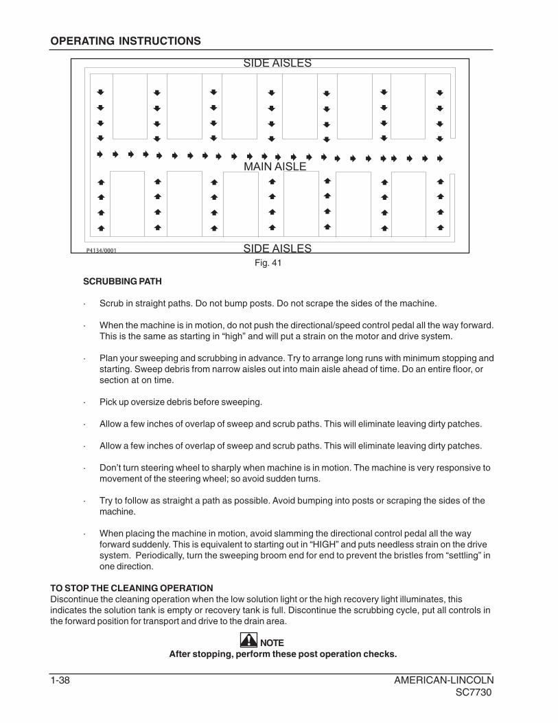
SCRUBBING PATH
· Scrub in straight paths. Do not bump posts. Do not scrape the sides of the machine.
· When the machine is in motion, do not push the directional/speed control pedal all the way forward.
This is the same as starting in “high” and will put a strain on the motor and drive system.
· Plan your sweeping and scrubbing in advance. Try to arrange long runs with minimum stopping and
starting. Sweep debris from narrow aisles out into main aisle ahead of time. Do an entire floor, or
section at on time.
· Pick up oversize debris before sweeping.
· Allow a few inches of overlap of sweep and scrub paths. This will eliminate leaving dirty patches.
· Allow a few inches of overlap of sweep and scrub paths. This will eliminate leaving dirty patches.
· Don’t turn steering wheel to sharply when machine is in motion. The machine is very responsive to
movement of the steering wheel; so avoid sudden turns.
· Try to follow as straight a path as possible. Avoid bumping into posts or scraping the sides of the
machine.
· When placing the machine in motion, avoid slamming the directional control pedal all the way
forward suddenly. This is equivalent to starting out in “HIGH” and puts needless strain on the drive
system. Periodically, turn the sweeping broom end for end to prevent the bristles from “settling” in
one direction.
TO STOP THE CLEANING OPERATION
Discontinue the cleaning operation when the low solution light or the high recovery light illuminates, this
indicates the solution tank is empty or recovery tank is full. Discontinue the scrubbing cycle, put all controls in
the forward position for transport and drive to the drain area.
NOTE
After stopping, perform these post operation checks.
P4134/0001
SIDE AISLES
MAIN AISLE
SIDE AISLES
Fig. 41
OPERATING INSTRUCTIONS

AMERICAN-LINCOLN 1-39
SC7730
POST OPERATION CHECKLIST
Check Battery Condition and recharge, if necessary.
1. Check all flaps for wear, damage and adjustment.
2. Drain and clean recovery tank.
3. Clean recovery tank screen and float.
4. Check scrub brushes for wear or damage.
5. Check rear and side squeegee for wear, damage and adjustment.
6. Clean the debris in hopper
7. Check main and side broom for wear or damage.
TO DRAIN RECOVERY TANK
The drain hose for the recovery tank is located on the back of the machine. To drain the tank, remove and lower
the hose and place in a suitable floor drain as shown in figure 44. Open the drain hose plug as shown in figure
42 and 43.
IMPORTANT
Improper discharge of wastewater will damage the environment and is illegal. The U.S.
Environmental Protection Agency has established certain regulations regarding discharge of
wastewater. The local city and state regulations regarding wastewater discharge may be in effect in
your area. Understand and follow the regulations in your area. Be aware of the environmental
hazards associated with the substances you dispose of.
DRAIN HOSE
DRAIN HOSE PLUG
DRAIN HOSE
DRAIN HOSE PLUG
TO DRAIN RECOVERY TANK
PLACE HOSE OVER DRAIN
Fig. 45
Fig. 42 Fig. 43
WHEN REPLACING DRAIN HOSE
CLIP ON DRAIN HOSE PLUG
FACES OUT
Fig. 44
OPERATING INSTRUCTIONS

1-40 AMERICAN-LINCOLN
SC7730
RECOVERY TANK HOSE
RECOVERY TANK
RECOVERY TANK HOSE
RECOVERY TANK SCREEN
DRAIN HOSE
RECOVERY TANK
CLEAN OUT DOORKNOB
DRAIN HOSE PLUG
RECOVERY TANK
CLEAN OUT DOOR OPEN
When the draining operation is complete, open the recovery tank clean out door as shown in figure 49 and flush
the recovery drain hose as shown in figure 46. Clean the recovery tank and recovery tank screen as shown in
figure 47. Close the recovery tank clean out door, drain hose plug, the recovery tank lid and clip the drain hose
into place as shown in figure 48.
Fig. 46 Fig. 47
Fig. 48 Fig. 49
OPERATING INSTRUCTIONS

AMERICAN-LINCOLN 1-41
SC7730
OPERATING INSTRUCTIONS
DISK SCRUB BRUSHESDISK SCRUB BRUSH
MAIN BROOM
SIDE BROOM
Fig. 50 Fig. 51
Fig. 52 Fig. 53
Inspect the disk scrub brushes and replace when the bristles are reduced to ¾ in length as shown in figure 50
and 51. To order replacement brushes, see scrub brush options in this manual.
Inspect the main and side broom. When the bristles are worn to 1 1/2 inch length replace the main broom as
shown in figure 52 and replace side broom when bristles are worn to 3 1/2 inch as shown in figure 53.

1-42 AMERICAN-LINCOLN
SC7730
OPERATING INSTRUCTIONS
REAR SQUEEGEE
TOP OR REAR SQUEEGEE
BOTTOM OF REAR SQUEEGEE
SIDE SQUEEGEE
Fig. 54 Fig. 55
Fig. 56
Inspect the rear and side squeegee blades for wear. If the wiping edge becomes rounded, remove and reinstall
so the unworn edge is now the wiping edge. This process can be repeated until all four edges are worn. If the
squeegee blade has become rippled, it will need to be replaced.

AMERICAN-LINCOLN 1-43
SC7730
DUST CONTROL
KNOB
DUST CONTROL
PANEL FILTER
Fig. 57 Fig. 58
DUST CONTROL KNOB
The dust control knob is used to hold the dust control filter cover down as shown in figure 57. The dust control
filter is located under the front cover and will need to be removed periodically for cleaning or replacement.
Removal of the filter panel requires no tools. The front cover must be opened to gain access to the filter
compartment. The panel filter is held in place by a hinged frame and knob. To remove the panel filter, turn the
knob counterclockwise and lift the hinged frame. The panel filter can now be lifted out and cleaned or replaced.
To install the replacement panel filter, place a new filter in the machine, lower the frame and twist the knob
clockwise to lock the filter in place.
FILL WITH
HYDRAULIC FLUID
CHECK FLUID LEVEL
HYDRAULIC RESERVOIR LEVEL SIGHT GAUGE
The sight gauge is located on the right side of the machine under the front cover as shown in figure 59. The sight
gauge is used to indicate the level of fluid in the reservoir. The fluid level must be visible in the sight gauge when
the hopper is in the down position.
Fig. 59
OPERATING INSTRUCTIONS

1-44 AMERICAN-LINCOLN
SC7730
SERVICE CHART
Check items for proper operation. If service is required, please contact an authorized American-Lincoln
Technology distributor. For best performance, replace worn parts with genuine American-Lincoln parts.
EVERY eight (8) HOURS or DAILY check and clean/adjust if necessary:
1 Inspect panel filter for damage and clean them.
2 Inspect and clean hopper.
3 Inspect and clean recovery tank screens and filters.
4 Check hydraulic fluid level.
5 Check all flaps for wear or damage.
6 Check brooms for wear or damage, adjust as required.
7 Check brake pedal and parking brake.
8 Check hydraulic oil filter.
9 Check battery electrolyte level.
10 Check all fluid system components for leaks.
50 HOUR (WEEKLY) MAINTENANCE CHECKLIST
11 Check solution tank (recycling or ESP system).
12 Check solution filter screen (recycling or ESP system).
13 Check recovery tank.
14 Check recovery tank screens and filters.
15 Inspect scrub brushes for wear or damage.
16 Inspect rear and side squeegees for wear or damage.
17 Check battery electrolyte level.
18 Check all hydraulic hoses for wear or cuts.
19 Rotate main brush.
20 Clean or replace panel filter.
21 Lubricate squeegee casters.
100 HOUR MAINTENANCE CHECKLIST
22 Lubricate front wheel bearings.
23 Lubricate all moving joints.
250 HOUR MAINTENANCE CHECKLIST
24 Lubricate squeegee casters.
25 Clean solution tank and filter screen.
26 Replace hydraulic filter element.
27 Clean hydraulic reservoir.
MAINTENANCE

AMERICAN-LINCOLN 1-45
SC7730
MAINTENANCE
3, 13, 1411, 12, 25
5, 6 4, 8,
26, 27
5, 19
21, 24
7 9, 17 181, 20
6
1615 16
5 22, 23
6
2
1-46 AMERICAN-LINCOLN
SC7730
MAINTENANCE
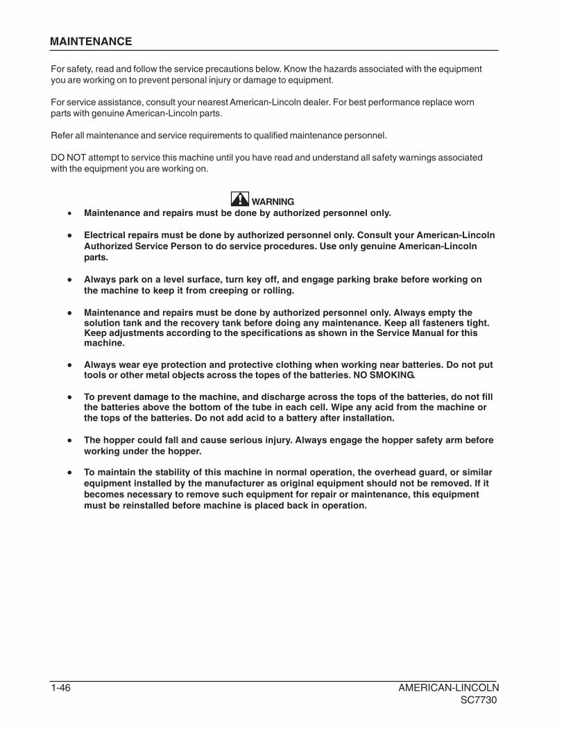
For safety, read and follow the service precautions below. Know the hazards associated with the equipment
you are working on to prevent personal injury or damage to equipment.
For service assistance, consult your nearest American-Lincoln dealer. For best performance replace worn
parts with genuine American-Lincoln parts.
Refer all maintenance and service requirements to qualified maintenance personnel.
DO NOT attempt to service this machine until you have read and understand all safety warnings associated
with the equipment you are working on.
WARNING
• Maintenance and repairs must be done by authorized personnel only.
••••• Electrical repairs must be done by authorized personnel only. Consult your American-Lincoln
Authorized Service Person to do service procedures. Use only genuine American-Lincoln
parts.
••••• Always park on a level surface, turn key off, and engage parking brake before working on
the machine to keep it from creeping or rolling.
••••• Maintenance and repairs must be done by authorized personnel only. Always empty thesolution tank and the recovery tank before doing any maintenance. Keep all fasteners tight.Keep adjustments according to the specifications as shown in the Service Manual for thismachine.
••••• Always wear eye protection and protective clothing when working near batteries. Do not puttools or other metal objects across the topes of the batteries. NO SMOKING.
••••• To prevent damage to the machine, and discharge across the tops of the batteries, do not fillthe batteries above the bottom of the tube in each cell. Wipe any acid from the machine orthe tops of the batteries. Do not add acid to a battery after installation.
••••• The hopper could fall and cause serious injury. Always engage the hopper safety arm before
working under the hopper.
••••• To maintain the stability of this machine in normal operation, the overhead guard, or similar
equipment installed by the manufacturer as original equipment should not be removed. If it
becomes necessary to remove such equipment for repair or maintenance, this equipment
must be reinstalled before machine is placed back in operation.

AMERICAN-LINCOLN 1-47
SC7730
MAINTENANCE
MACHINE POWER CONNECTOR
BATTERY POWER CONNECTOR
BATTERY CHARGING INSTRUCTIONS
When the battery conditioning meter is illuminated with one red LED light, the battery needs to be recharged.
To prevent interruption of the cleaning cycle, charge the battery after using.
1. Lift the machine front cover.
2. Disconnect the battery power connector from the machine power connector.
3. Plug the battery power connector into the battery charger.
4. Follow manufacturer’s charging instructions provided on the charger.
5. Maintain electrolyte level in battery, check after charging. Add distilled water as needed.
Fig. 60 Fig. 61
Fig. 62
LIFT MACHINE
FRONT COVER
TO ACCESS
BATTERY
CONNECT POSITIVE TO
POSITIVE AND NEGATIVE
TO NEGATIVE
1-48 AMERICAN-LINCOLN
SC7730
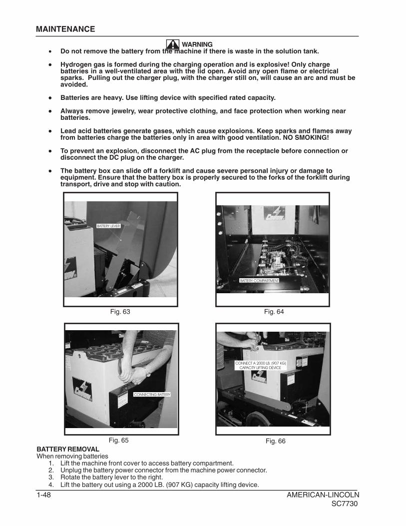
BATTERY REMOVALWhen removing batteries
1. Lift the machine front cover to access battery compartment.2. Unplug the battery power connector from the machine power connector.3. Rotate the battery lever to the right.4. Lift the battery out using a 2000 LB. (907 KG) capacity lifting device.
BATTERY LEVER
CONNECT A 2000 LB. (907 KG)
CAPACITY LIFTING DEVICE
Fig. 63 Fig. 64
Fig. 65
CONNECTING BATTERY
MAINTENANCE
WARNING• Do not remove the battery from the machine if there is waste in the solution tank.
••••• Hydrogen gas is formed during the charging operation and is explosive! Only chargebatteries in a well-ventilated area with the lid open. Avoid any open flame or electricalsparks. Pulling out the charger plug, with the charger still on, will cause an arc and must beavoided.
••••• Batteries are heavy. Use lifting device with specified rated capacity.
••••• Always remove jewelry, wear protective clothing, and face protection when working nearbatteries.
••••• Lead acid batteries generate gases, which cause explosions. Keep sparks and flames awayfrom batteries charge the batteries only in area with good ventilation. NO SMOKING!
••••• To prevent an explosion, disconnect the AC plug from the receptacle before connection ordisconnect the DC plug on the charger.
••••• The battery box can slide off a forklift and cause severe personal injury or damage toequipment. Ensure that the battery box is properly secured to the forks of the forklift duringtransport, drive and stop with caution.
BATTERY COMPARTMENT
Fig. 66

AMERICAN-LINCOLN 1-49
SC7730
MAINTENANCE
BATTERY REMOVAL WITH THE BATTERY ROLLOUT OPTION
When removing batteries
1. Lift the machine front cover to access battery compartment.
2. Unplug the battery power connector from the machine power connector.
3. Line up battery cart locator pins with slots in frame and lock in place.
4. Rotate the battery lever to the right.
5. Roll battery out on to cart.
BATTERY CART
LINE UP BATTERY CART LOCATOR PINS
TO THE SLOTS IN THE FRAME
BATTERY CART
BATTERY LEVER
BATTERY CARTBATTERY LEVER
Fig. 67
Fig. 70Fig. 69
Fig. 68
1-50 AMERICAN-LINCOLN
SC7730
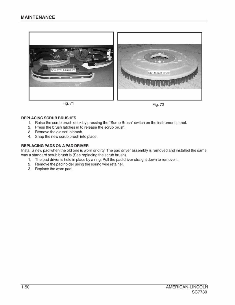
REPLACING SCRUB BRUSHES
1. Raise the scrub brush deck by pressing the “Scrub Brush” switch on the instrument panel.
2. Press the brush latches in to release the scrub brush.
3. Remove the old scrub brush.
4. Snap the new scrub brush into place.
REPLACING PADS ON A PAD DRIVER
Install a new pad when the old one is worn or dirty. The pad driver assembly is removed and installed the sameway a standard scrub brush is (See replacing the scrub brush).
1. The pad driver is held in place by a ring. Pull the pad driver straight down to remove it.
2. Remove the pad holder using the spring wire retainer.
3. Replace the worn pad.
DISK SCRUB BRUSHESDISK SCRUB BRUSH
Fig. 71 Fig. 72
MAINTENANCE

AMERICAN-LINCOLN 1-51
SC7730
LOOSEN KNOB
TOP OR REAR SQUEEGEE
BOTTOM OF REAR SQUEEGEE
REPLACING REAR SQUEEGEE
The squeegee will require service when the inner edge of the blades become round with wear, impairing the
wiping action or water pick up.
1. Loosen the four aluminum knobs.
2. Remove the squeegee tool and turn upside down to service the blades or the caster wheels. The
squeegee blades are designed to rotate to use an unworn edge.
3. Loosen the clamp bolts.
4. Install blades so that the outer blade is 3/16" longer than the inner blades. This is achieved by
assembling the top edge of the blade against the squeegee tool weldment.
5. Reinstall the squeegee clamp band and tighten the clamp bolt.
TO CHANGE SQUEEGEE BLADE
REMOVE NUT AND TURN
SQUEEGEE BLADE OVER
Fig. 73
Fig. 75
Fig. 74
MAINTENANCE

1-52 AMERICAN-LINCOLN
SC7730
DRAINING THE RECOVERY TANK
Drive the machine to a draining area. Loosen the knobs on the recovery clean out door and pivot the door to the
left as shown in figure 76. With the water hose flush out the bottom of the recovery tank clean out door to
remove larger particles of debris.
MAINTENANCE
FLUSH OUT THE RECOVERY TANK WITH
A WATER HOSE OR PRESSURE WASHER
SOLUTION TANK DRAIN HOSE
SOLUTION TANK DRAIN HOSE
DRAINING THE SOLUTION TANK
Lift the cover on the solution/recovery tank. Locate the solution tank drain hose as shown in figure 77. Pull the
hose out as shown in figure 78. Open the solution tank drain plug and let the solution tank drain. Clean out and
flush the solution tank with a water hose. Tighten the solution tank plug and tuck the solution tank drain hose
into place.
Fig. 76
Fig. 77 Fig. 78

AMERICAN-LINCOLN 1-53
SC7730
MAINTENANCE
MAIN BROOM
MAIN BROOM
To prevent the broom from setting in one direction and to provide the maximum life of the broom it is
recommended that the broom be turned end over end periodically.
ADJUSTING THE MAIN BROOM HEIGHT
The main broom adjustment knob for changing the sweep height to compensate for broom wear is located in
front of the machine as shown in figure 80. Turning the knob to the left (counterclockwise) will lower the main
broom. When changing the sweep height adjustment, it is recommended the knob be adjusted one turn at a
time. After adjusting, recheck the sweep pattern to determine if further adjustment is necessary.
TURN KNOB CLOCKWISE = INCREASE SWEEP PATTERN WIDTH
TURN KNOB COUTERCLOCKWISE = DECREASE SWEEP PATTERN WIDTH
Fig. 79
Fig. 80
MAIN BROOM ADJUSTMENT KNOB

1-54 AMERICAN-LINCOLN
SC7730
MAINTENANCE
BROOM LIFT ARM KNOBS
BROOM LIFT ARM
WITH KNOBS REMOVED
MAIN BROOM ACCESS DOOR
Fig. 81
Fig. 82 Fig. 83
REPLACING THE MAIN BROOM
The Main Broom should be replaced when the bristles become worn to less than 1 1/2”. The main broom is
held in place by the right side broom door. This feature provides for easy removal and installation of the main
broom without the need for special tools or equipment. Lift the hopper to gain access to the main broom
compartment. Loosen the main broom access door knob and open the main broom access door. Rotate and
remove the broom lift arm knobs counterclockwise to the left as shown in figure 82 and 83.
MAIN BROOM ACCESS DOOR
The main broom access door is located in front of the left side tire of the machine as shown in figure 81. The
door provides access to the main broom for service or inspection. The hopper must be raised to access.
WARNINGEngage hopper safety arm while accessing the main broom

AMERICAN-LINCOLN 1-55
SC7730
SLIDE BROOM ONTO
BROOM IDLER
REMOVE BROOM LIFT ARM
MAINTENANCE
BROOM LIFT ARM
BROOM IDLER
BROOM IDLER
Fig. 84 Fig. 85
Fig. 86 Fig. 87
Remove broom lift arm as shown in figure 84 and 85. Remove the main broom from the from the broom idler
exposing the main broom compartment as shown in figure 86. Check and clean out the main broom
compartment before installing the new main broom. Slide the main broom onto the broom idler as shown in
figure 87. Replace the broom lift arm and rotate the broom lift arm knobs clockwise to tighten into place as
shown in figure 88. Adjust the main broom to 1-1/2” to 2” sweep pattern.
INSTALLED BROOM
Fig. 88

1-56 AMERICAN-LINCOLN
SC7730
SIDE BROOM ADJUSTMENT KNOB
MAINTENANCE
SIDE BROOM
The side broom (Fig. 89) sweeping angle is not
adjustable. However, the height of the side
broom can be adjusted to compensate as the
broom becomes worn from use. Always check
and adjust the sweep pattern after changing the
side broom.
ADJUSTING THE SIDE BROOM HEIGHT
Turn the side broom adjustment knob (Fig. 90)
to change the side broom sweep height.
Recheck for proper sweep pattern after
adjustment.
Turn the adjustment knob counterclockwise to
INCREASE the sweep pattern width.
Turn the adjustment knob clockwise to
DECREASE the sweep pattern width.
REPLACING THE SIDE BROOM
Change the side broom (Fig. 91) when the
bristles become worn to less than 3 inches
length.
1. Park the machine on a smooth level
surface, turn key switch to “O” Position and
engage parking brake.
2. Place the side brooms switch in the “UP”
position.
3. Remove the lock pin that holds the broom
flange to the motor shaft.
4. Disassemble the flange from the broom by
removing the screws that hold the flange to
the broom.
5. Assemble the flange to the replacement
broom and fasten using the hardware
removed.
6. Install the replacement broom on the shaft
and insert the lock pin.
Fig. 89
Fig. 90
Fig. 91

AMERICAN-LINCOLN 1-57
SC7730
MAINTENANCE
HOPPER
Fig. 92 Fig. 93
HOPPER
The hopper (Fig. 92) houses the debris compartment, the dust control filter and the removable dust baffle. For
maximum performance and service life, keep the hopper clean and inspect the seals and flaps daily. Clean
the hopper prior to parking the sweeper at the end of the day. A clean hopper will make inspecting the flaps
and seals much easier and will prevent premature deterioration of hopper components. Do not leave the
hopper full of debris while in storage or when parked for extended periods of time. Once the hopper has been
emptied the insides of the hopper should be rinsed out with water.
DUST CONTROL FILTER
The dust control filter (Fig. 93) should be checked daily for damage and cleaned if necessary. A damaged filter
must be replaced to prevent damage to other dust control system components. Inspect the filter for tears in
the filter media or excessive dirt lodged in the pleats. A tear in the filter media will allow dirt to pass through
the filter and can be easily seen as a dirty patch on the top side on the filter. Cleaning of the filter is
necessary when the filter shaker fails to adequately clean the pleats.
CHECKING THE DUST CONTROL FILTER
1. Park the machine on a smooth level surface, turn the key switch to the “O” position and engage the
parking brake.
2. Raise the hopper lid for access to the filter compartment.
3. Turn the filter latch, lift the filter frame and remove the filter.
4. Inspect the panel filter for tears and clean or replace if necessary.
5. Reinstall the filter, lower the filter frame and engage the filter latch.
6. Close the hopper cover.
CLEANING THE DUST CONTROL FILTER
Clean the dust control filter when the shaker fails to adequately clear the filter. The filter can be cleaned with
compressed air not to exceed 100 PSI. To clean the filter with compressed air, apply the compressed air to
the top side of the panel to back flush the lodged dirt from the filter pleats. Be careful to not damage the filter
media while cleaning. The filter can be cleaned with a solution of soap and water. If this cleaning method is
used do not use the filter until it has completely dried.
REPLACING THE DUST CONTROL FILTER WHEN DAMAGE IS EVIDENT
1. Park the machine on a smooth level surface, turn the key switch to the “O” position and engage the
parking brake.
2. Open the hopper compartment cover to gain access to the filter compartment.
3. Turn the latch on the hinged frame counterclockwise and lift the frame .
4. Remove the filter panel.
5. Install replacement filter, lower the hinged frame and engage the latch.
6. Lower the filter compartment cover.
DUST CONTROL
PANEL FILTER

1-58 AMERICAN-LINCOLN
SC7730
DUST FLAPSThe dust flaps are very important to sweeping and dust control and are susceptible to damage and should beinspected daily and maintained in good condition.
CHECKING THE DUST FLAPSThe dust flaps are used on the wheel well, broom chamber and broom door. Inspect the flaps daily and replaceany flap that shows signs of wear or deterioration. All flaps should be replaced when worn or damaged to thepoint that they can no longer perform their normal function. The adjustable flaps have slotted mounting holes tofacilitate adjustment.
ADJUSTING THE DUST FLAPSAdjust the flaps so there is a 1/8" to 1/16" gap between the floor and the bottom edge of the flaps. The rearflapadjustment is 1/16" (16 cm.) above the floor.1. Park the machine on a smooth level surface and engage the parking brake.2. Loosen the flap retaining screws and adjust the flap to clear the floor and leave a 1/16" to 1/8" gap.3. Tighten flap retaining screws while holding flap in position.4. Drive the machine on a smooth surface and recheck the flaps for proper floor clearance.
MAINTENANCE
FILL WITH
HYDRAULIC FLUID
CHECK FLUID LEVEL
Fig. 94
FILLING THE HYDRAULIC RESERVOIR (Fig. 94)1. Access to the hydraulic reservoir is located in the engine compartment. 2. Open the hydraulic reservoir breather filter cap. 3. Remove any debris that is in the breather filter cap screen. 4. Fill the reservoir until the fluid is at the “FULL” line on the hydraulic fluid sight gauge. The sight gauge is located on the center side of the hydraulic reservoir. 5. Close the hydraulic reservoir breather filter cap. 6. Close the engine compartment cover.
CLEANING THE HYDRAULIC SYSTEM1. Put a drop cloth on the floor.2. Drive the machine onto the drop cloth.3. Set the parking brake.4. Open the hood.5. Put a container under the reservoir drain to catch the
reservoir fluid. Pivot the reservoir out.6. Remove the drain plug. The reservoir fluid will drain.
Do not use the drained fluid to refill the hydraulicreservoir. Dispose of the used fluid.
7. Flush the interior of the hydraulic reservoir with cleanfluid.
8. Put the reservoir plug, removed in step six, back in thehydraulic tank drain and tighten it. A pipe thread
sealer is required on the plug.9. Open the breather filter cap.10. Fill the reservoir with new MOBIL Multipurpose ATF or
equilvalent Dextron III. The capacity of the tank is 4.7 gal (17.79 liters). Fill to the “FULL” line on the
hydraulic fluid sight gauge.11. Close the breather filter cap.12. Replace the hood.
FILTER
REPLACING THE RETURN FILTER ELEMENT (Fig. 95)1. Replace the return filter element after 250 hours of machine run time.2. Unscrew the fasteners from the filter assembly cover and retain.3. Remove the cover and the compression spring and retain.4. Discard the old filter element.5. Position the new filter element inside the filter body.6. Put the compression spring in position. Wipe the cover magnet free of any metal filings or debris.7. Place O-ring (moisten with clean hydraulic fluid) and cover into position.8. Reattach fasteners to the filter cover.9. Clean any hydraulic reservoir fluid spills. The fluid can damage painted surfaces of the machine.
Fig. 95
AMERICAN-LINCOLN 1-59
SC7730
TROUBLESHOOTING
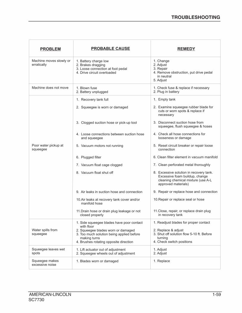
PROBLEM PROBABLE CAUSE REMEDY
Machine moves slowly orerratically
Machine does not move
Poor water pickup atsqueegee
Water spills fromsqueegee
Squeegee leaves wetspots
Squeegee makesexcessive noise
1. Battery charge low2. Brakes dragging3. Loose connection at foot pedal4. Drive circuit overloaded
1. Blown fuse2. Battery unplugged
1. Recovery tank full
2. Squeegee is worn or damaged
3. Clogged suction hose or pick-up tool
4. Loose connections between suction hoseand squeegee
5. Vacuum motors not running
6. Plugged filter
7. Vacuum float cage clogged
8. Vacuum float shut off
9. Air leaks in suction hose and connection
10.Air leaks at recovery tank cover and/ormanifold hose
11.Drain hose or drain plug leakage or notclosed properly
1. Side squeegee blades have poor contactwith floor
2. Squeegee blades worn or damaged3. Too much solution being applied before
making turns4. Brushes rotating opposite direction
1. Lift actuator out of adjustment2. Squeegee wheels out of adjustment
1. Blades worn or damaged
1. Change2. Adjust3. Repair4. Remove obstruction, put drive pedal
in neutral5. Adjust
1. Check fuse & replace if necessary2. Plug in battery
1. Empty tank
2. Examine squeegee rubber blade forcuts or worn spots & replace ifnecessary
3. Disconnect suction hose fromsqueegee, flush squeegee & hoses
4. Check all hose connections forlooseness or damage
5. Reset circuit breaker or repair looseconnection
6. Clean filter element in vacuum manifold
7. Clean perforated metal thoroughly
8. Excessive solution in recovery tank.Excessive foam buildup, changecleaning chemical mixture (use A-Lapproved materials)
9. Repair or replace hose and connection
10.Repair or replace seal or hose
11.Close, repair, or replace drain plugin recovery tank
1. Readjust blades for proper contact
2. Replace & adjust3. Shut off solution flow 5-10 ft. Before
turning4. Check switch positions
1. Adjust2. Adjust
1. Replace

1-60 AMERICAN-LINCOLN
SC7730
TROUBLESHOOTING
PROBLEM PROBABLE CAUSE REMEDY
Poor scrubbing action
Water splashes from sidesof scrub deck
Poor sweeping
Sweep does notfunction
Poor dust control at mainbroom
Hopper will not lift
1. Worn scrubbing brushes
2. Incorrect method of operation
3. Wrong cleaning agent or mixture
4. Poor solution distribution
5. Brushes won’t turn
1. Scrub deck bumpers, poor contact with floor2. Squeegee blades word or damaged3. Too much solution
1. Broom jammed2. Hopper full3. Broom not adjusted properly4. Worn or damaged flaps5. Worn broom
1. Hopper is raised2. Hopper switch out of adjustment
1. Broom chamber & hopper flaps worn
2. Impellor fan failure - shaft key broken orelectric motor not operating
3. Filter plugged
1. Load too heavy2. Defective lift actuator
1. Inspect brushes. Replace if brushes areworn to 3/4” or less.
2. Check scrubbing procedure, brushpressure, solution flow & cleaning agentused - all are important to the process
3. Use A-L recommended materials
4. Check solution strainer & feed hoses forobstructions - clean if necessary.Check valve & rest of solution controlsystem for proper operation.
5. Check wiring connections
1. Readjust blades for proper contact2. Replace & adjust3. Shut off solution flow 5-10 ft. before
making turns
1. Remove any obstruction2. Empty3. Refer to broom adjustment in
maintenance section4.
1. Lower hopper2. Adjust hopper switch
1. Check condition of flaps. Replace torn orbadly worn flaps. Side flaps can beadjusted of not damaged.2. Check & repair
3. Engage shaker switch or check filter
1. Low dump partial load2. Repair or replace actuator
Inspect for damage - replace or adjustby referring to maintenance section
5. Inspect for damage or wear - refer tomaintenance section

AMERICAN-LINCOLN 1-61
SC7730
NOTES


AMERICAN-LINCOLN FORM NO. 28600321 - 2-1SC7730
INDEX
AACCESS PANELS ............................................................................................................................65BBATTERY ROLLOUT .......................................................................................................................78BRAKE ASSEMBLY .........................................................................................................................18DDECALS ...........................................................................................................................................80DRIVE WHEEL ASSEMBLY .............................................................................................................14DUST CONTROL .............................................................................................................................54EELECTRICAL/CONNECTION DIAGRAMS ......................................................................................72ELECTRICAL/HARNESS ROUTING ...............................................................................................76ELECTRICAL/SCHEMATIC .............................................................................................................71ELECTRICAL/SCRUB DECK CONNECTION DIAGRAM ................................................................77FFORWARD/REVERSE ASSEMBLY .................................................................................................22FRONT COVER & LATCHES ...........................................................................................................60FRONT WHEEL ASSEMBLY ............................................................................................................16HHOPPER ASSEMBLY ......................................................................................................................52HORN ASSEMBLY ...........................................................................................................................64HYDRAULIC CONNECTION DIAGRAM ..........................................................................................86HYDRAULICS/LOW DUMP CYLINDER ..........................................................................................89HYDRAULIC MANIFOLD CONNECTIONS ......................................................................................70HYDRAULICS/MAIN BROOM MOTOR ...........................................................................................91HYDRAULICS/REAR SQUEEGEE LIFT CYLINDER .......................................................................90HYDRAULICS SCHEMATIC .........................................................................................................70.5HYDRAULICS/40” SCRUB DECK LIFT CYLINDER ........................................................................92HYDRAULICS/46” SCRUB DECK LIFT CYLINDER ........................................................................93HYDRAULICS/STEERING CYLINDER & PUMP .............................................................................88HYDRAULICS SYSTEM...................................................................................................................84IINSTRUMENT PANEL ......................................................................................................................66MMAIN BROOM ....................................................................................................................................6MAIN FRAME, BROOM BAFFLE & FLAPS .......................................................................................2PPOWER PANEL................................................................................................................................68POWER STEERING .........................................................................................................................20RREAR SQUEEGEE (40”) ..................................................................................................................44REAR SQUEEGEE (46”) ..................................................................................................................46RECOVERY TANK ...........................................................................................................................28SSCRUB DECK (40”) .........................................................................................................................30SCRUB DECK LIFT (40”) .................................................................................................................32SCRUB DECK & LIFT (46”) ..............................................................................................................36SCRUB DECK SOLUTION FEED HOSES (40”) ..............................................................................34SCRUB DECK SOLUTION FEED HOSES (46”) ..............................................................................40SEAT ASSEMBLY ............................................................................................................................62SIDE BROOM ...................................................................................................................................10SIDE SQUEEGEE (40”) ...................................................................................................................50SIDE SQUEEGEE (46”) ...................................................................................................................51SOLUTION CONTROL .....................................................................................................................24SOLUTION TANK .............................................................................................................................26SQUEEGEE LIFT .............................................................................................................................42SWING SQUEEGEE SUPPORT ......................................................................................................48VVACUUM MANIFOLD ASSEMBLY ...................................................................................................58

2-2 - FORM NO. 28600321 AMERICAN-LINCOLN
SC7730
MAIN FRAME, BROOM BAFFLE & FLAPS
KEY NO. QTY PART NUMBER DESCRIPTION
1 1 7-27-07224 MAIN FRAME WELDMENT
2 5 7-66-05011-1 ROLLER, BUMPER
3 1 7-32-00042 HINGE, M.B. BAFFLE
4 1 7-05-01003 BAFFLE, MAIN BROOM
5 3 7-13-07203 CLAMP, MB CHAMBER (rear fl ap)
6 1 7-25-08088 FLAP, MB RIGHT SIDE
7 1 7-13-07207 CLAMP, FLAP (left)
8 1 7-13-07206 CLAMP, FLAP (RH front)
9 1 7-16-07418 COVER, DUST COVER
10 3 7-70-05175 PIN-ROLLER BUMPER
11 8 2-00-00540 RING, RET. EXT. #5100-75, 3/4 D.
12 1 7-70-05188 PIN, ROLLER BUMPER (SB)
13 10 2-00-03940 SCREW, T/C HH #10-24 x .50 LG
14 1 2-00-00196 BOLT, CARR, .31-18 X 1 GR 5 ZN
15 1 2-00-00409 FLAT WASHER, .687 x .344 x .062
16 1 2-00-00644 HEX NUT, INSERT FIBER, 5/16-18
17# Intentionally Omitted
18# Intentionally Omitted
19 1 7-25-08091 FLAP, MB REAR
20 5 2-00-03575 BOLT, CARR, .25-20 x .75 GR5 ZN
21 10 2-00-00641 NUT, FIBER INSERT 1/4-20
22 1 7-29-00263 GASKET, DUST CONTROL
23# Intentionally Omitted
24 5 2-00-00221 HEX BOLT, FINISHED, 1/4-20 x 3/4 lg
25 4 2-00-00530 LOCK WASHER, 5/16”
26 4 2-00-00208 SCREW, 5/16-18 x .750 HHC
# = Revised or new since last update
c1019/0403
revised 9/07

AMERICAN-LINCOLN FORM NO. 28600321 - 2-3
SC7730
MAIN FRAME, BROOM BAFFLE & FLAPS
revised 9/07

2-4 - FORM NO. 28600321 AMERICAN-LINCOLN
SC7730
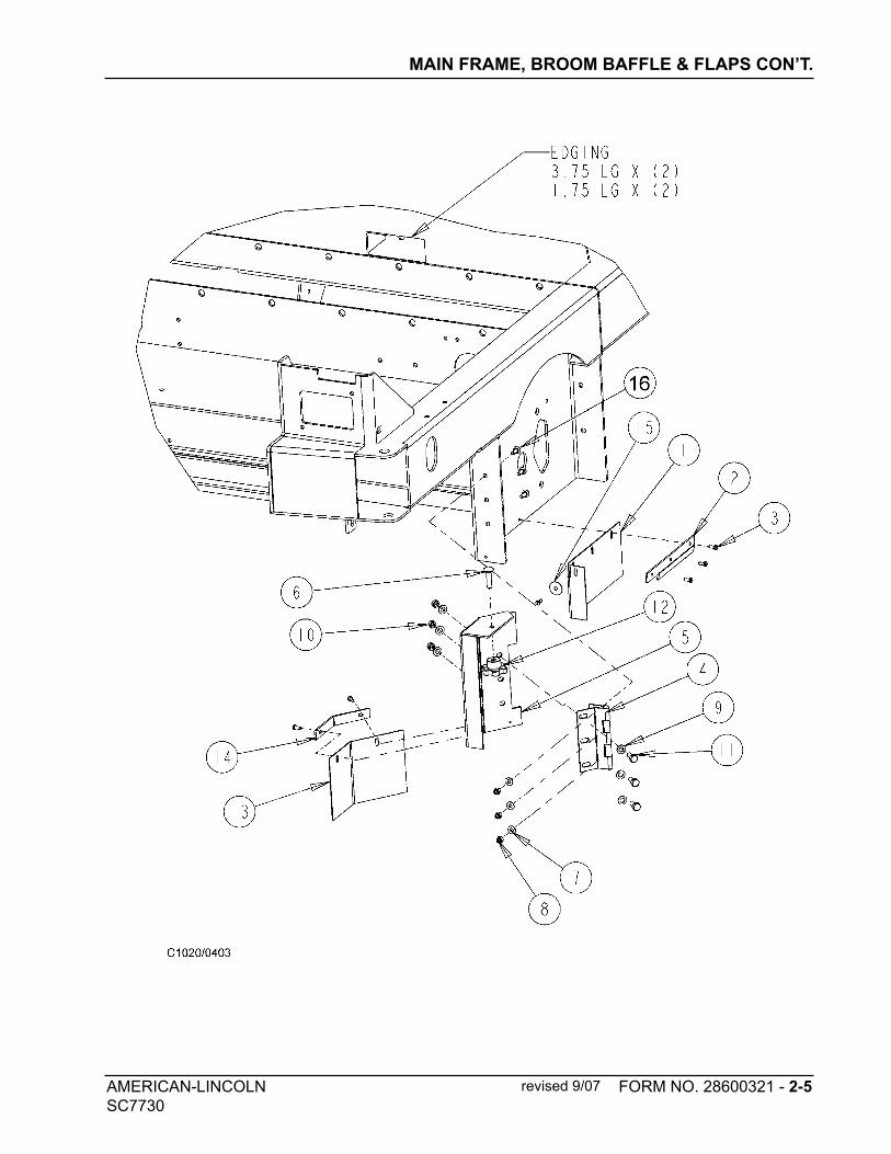
MAIN FRAME, BROOM BAFFLE & FLAPS CON’T.
KEY NO. QTY PART NUMBER DESCRIPTION
1 1 7-25-08089 FLAP, MB (LEFT)
2 1 7-13-07204 CLAMP, FLAP (LEFT)
3 6 2-00-03940 SCREW, T/C HH #10-24 x .50 LG
4 1 7-32-00039 HINGE, BROOM DOOR
5# 1 56109302 PANEL, BROOM DOOR
6 1 2-00-03750 BOLT, CARRIAGE, 3/8-16 x 1.5”
7 3 2-00-03702 WASHER, .625 x .281 x .063
8 3 2-00-00641 NUT, FIBER INSERT 1/4-20
9 6 2-00-00409 FLAT WASHER, .687 x .344 x .062
10 3 2-00-00644 HEX NUT, INSERT FIBER, 5/16-18
11 3 2-00-00208 SCREW, 5/16-18 x .750 HHC
12 1 25201A KNOB
13 1 7-25-08090 FLAP, MB DOOR PANEL
14 1 7-13-07205 CLAMP, FLAP (PANEL)
15 1 2-00-01676 FLAT WASHR, 1.063x.266x.063 STL
16 3 2-00-03575 BOLT, CARR, .25-20 x .75 GR5 ZN
# = Revised or new since last update
c1020/0403
revised 9/07
AMERICAN-LINCOLN FORM NO. 28600321 - 2-5
SC7730
MAIN FRAME, BROOM BAFFLE & FLAPS CON’T.
revised 9/07
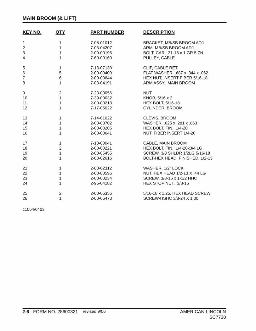
2-6 - FORM NO. 28600321 AMERICAN-LINCOLN SC7730
MAIN BROOM (& LIFT)
revised 9/06
KEY NO. QTY PART NUMBER DESCRIPTION
1 1 7-08-01012 BRACKET, MB/SB BROOM ADJ.2 1 7-03-04207 ARM, MB/SB BROOM ADJ.3 1 2-00-00196 BOLT, CAR, .31-18 x 1 GR 5 ZN4 1 7-60-00160 PULLEY, CABLE
5 1 7-13-07130 CLIP, CABLE RET.6 5 2-00-00409 FLAT WASHER, .687 x .344 x .0627 6 2-00-00644 HEX NUT, INSERT FIBER 5/16-188 1 7-03-04191 ARM ASSY., MAIN BROOM
9 2 7-23-03056 NUT10 1 7-39-00032 KNOB, 5/16 x 2 11 1 2-00-00218 HEX BOLT, 5/16-18 12 1 7-17-05022 CYLINDER, BROOM
13 1 7-14-01022 CLEVIS, BROOM14 1 2-00-03702 WASHER, .625 x .281 x .06315 1 2-00-00205 HEX BOLT, FIN., 1/4-2016 1 2-00-00641 NUT, FIBER INSERT 1/4-20
17 1 7-10-00041 CABLE, MAIN BROOM18 2 2-00-00221 HEX BOLT, FIN., 1/4-20x3/4 LG19 1 2-00-05455 SCREW, 3/8 SHLDR 1/2LG 5/16-1820 1 2-00-02616 BOLT-HEX HEAD, FINISHED, 1/2-13
21 1 2-00-02312 WASHER, 1/2” LOCK22 1 2-00-00596 NUT, HEX HEAD 1/2-13 X .44 LG23 1 2-00-00234 SCREW, 3/8-16 x 1-1/2 HHC24 1 2-95-04182 HEX STOP NUT, 3/8-16
25 2 2-00-05356 5/16-18 x 1.25, HEX HEAD SCREW26 1 2-00-05473 SCREW-HSHC 3/8-24 X 1.00
c1064/0403
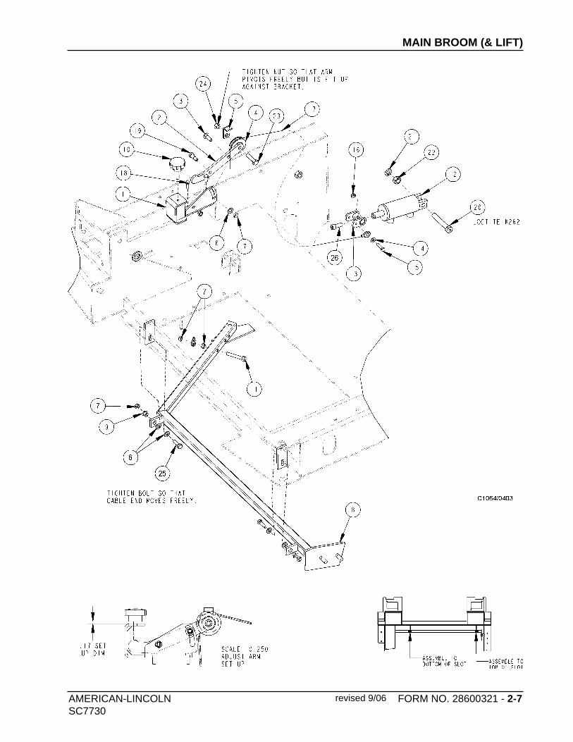
AMERICAN-LINCOLN FORM NO. 28600321 - 2-7SC7730
MAIN BROOM (& LIFT)
revised 9/06

2-8 - FORM NO. 28600321 AMERICAN-LINCOLN SC7730
MAIN BROOM (MOTOR)
revised 9/06
KEY NO. QTY PART NUMBER DESCRIPTION
1 1 7-03-04190 ARM, MAIN BROOM2 4 2-00-00221 HEX BOLT, FIN., 1/4-20 x 3/4 LG3 1 8-30-05112 GUARD4 2 2-00-03306 BALL BEARING
5 2 2-00-00641 NUT, FIBER INSERT 1/4-206 1 8-75-01147 SPACER, MB IDLER7 1 2-00-03158 SPACER8 1 8-33-09059 HUB, IDLER (WELDMENT)
9 1 2-00-02616 HEX BOLT, FIN., 1/2-1310 1 2-00-02312 LOCK WASHER, 1/2”11 1 2-00-00596 HEX NUT, 1/2-13 x .44 LG12 1 7-08-00938 BRACKET, MAIN BROOM
13 1 8-30-05116 GUARD, THREAD14 1 8-33-05086 HOUSING, MB MOTOR WELDMENT15 1 0885-078 HYD. MOTOR (BROOM DRIVE)16 5 2-00-00518 LOCK WASHER, 1/4” HEL. SPRNG
17 1 8-08-03137 MAIN BROOM18 1 2-00-00644 HEX NUT, INSERT FIBER 5/16-1819 2 25201A KNOB20 1 8-33-09062 HUB, MB (WELDMENT)
21 1 2-00-00218 BOLT-HEX HEAD, 5/16-1822 2 2-00-00263 Set Scr-HS Knurled Cup PT. #10-24 x 3/823 3 2-00-04750 SCREW-SOCKET, BUTTON HEAD, 1/4-224 1 2-00-03829 LOCK WASHER, 3/8 INT./EXT. TOOTH
c1065/0403
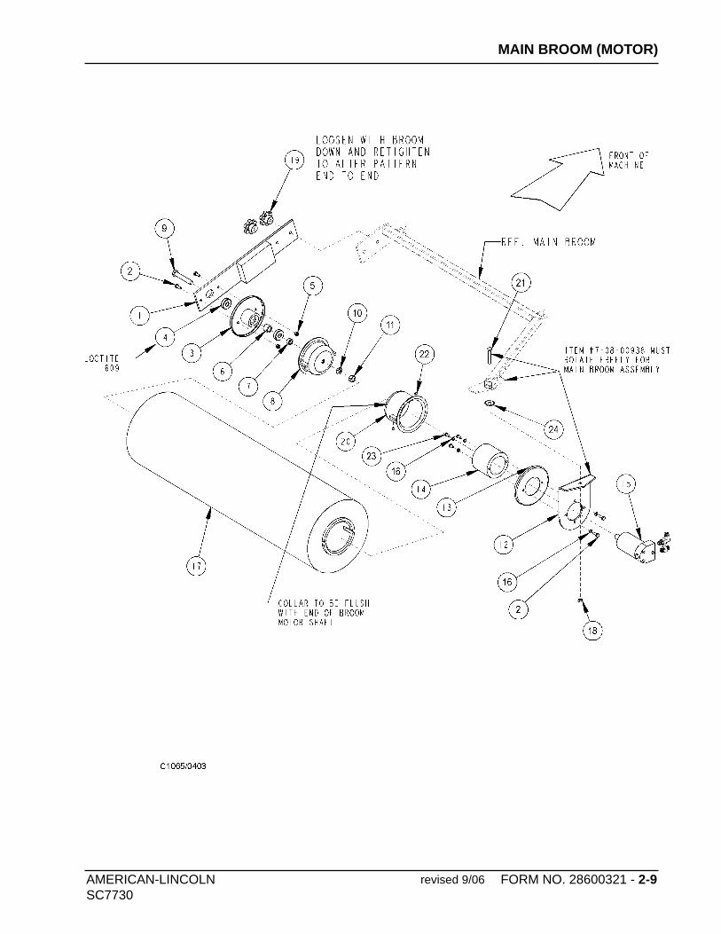
AMERICAN-LINCOLN FORM NO. 28600321 - 2-9SC7730
MAIN BROOM (MOTOR)
revised 9/06
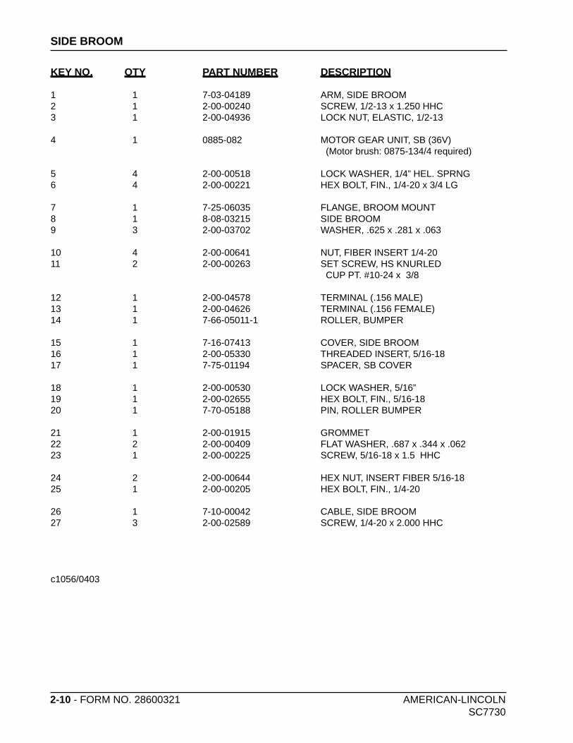
2-10 - FORM NO. 28600321 AMERICAN-LINCOLN SC7730
SIDE BROOM
KEY NO. QTY PART NUMBER DESCRIPTION
1 1 7-03-04189 ARM, SIDE BROOM2 1 2-00-00240 SCREW, 1/2-13 x 1.250 HHC3 1 2-00-04936 LOCK NUT, ELASTIC, 1/2-13
4 1 0885-082 MOTOR GEAR UNIT, SB (36V) (Motor brush: 0875-134/4 required)
5 4 2-00-00518 LOCK WASHER, 1/4” HEL. SPRNG6 4 2-00-00221 HEX BOLT, FIN., 1/4-20 x 3/4 LG
7 1 7-25-06035 FLANGE, BROOM MOUNT8 1 8-08-03215 SIDE BROOM9 3 2-00-03702 WASHER, .625 x .281 x .063
10 4 2-00-00641 NUT, FIBER INSERT 1/4-2011 2 2-00-00263 SET SCREW, HS KNURLED CUP PT. #10-24 x 3/8
12 1 2-00-04578 TERMINAL (.156 MALE)13 1 2-00-04626 TERMINAL (.156 FEMALE)14 1 7-66-05011-1 ROLLER, BUMPER
15 1 7-16-07413 COVER, SIDE BROOM16 1 2-00-05330 THREADED INSERT, 5/16-1817 1 7-75-01194 SPACER, SB COVER
18 1 2-00-00530 LOCK WASHER, 5/16”19 1 2-00-02655 HEX BOLT, FIN., 5/16-1820 1 7-70-05188 PIN, ROLLER BUMPER
21 1 2-00-01915 GROMMET22 2 2-00-00409 FLAT WASHER, .687 x .344 x .06223 1 2-00-00225 SCREW, 5/16-18 x 1.5 HHC
24 2 2-00-00644 HEX NUT, INSERT FIBER 5/16-1825 1 2-00-00205 HEX BOLT, FIN., 1/4-20
26 1 7-10-00042 CABLE, SIDE BROOM27 3 2-00-02589 SCREW, 1/4-20 x 2.000 HHC
c1056/0403

AMERICAN-LINCOLN FORM NO. 28600321 - 2-11SC7730
SIDE BROOM
C1056/0403
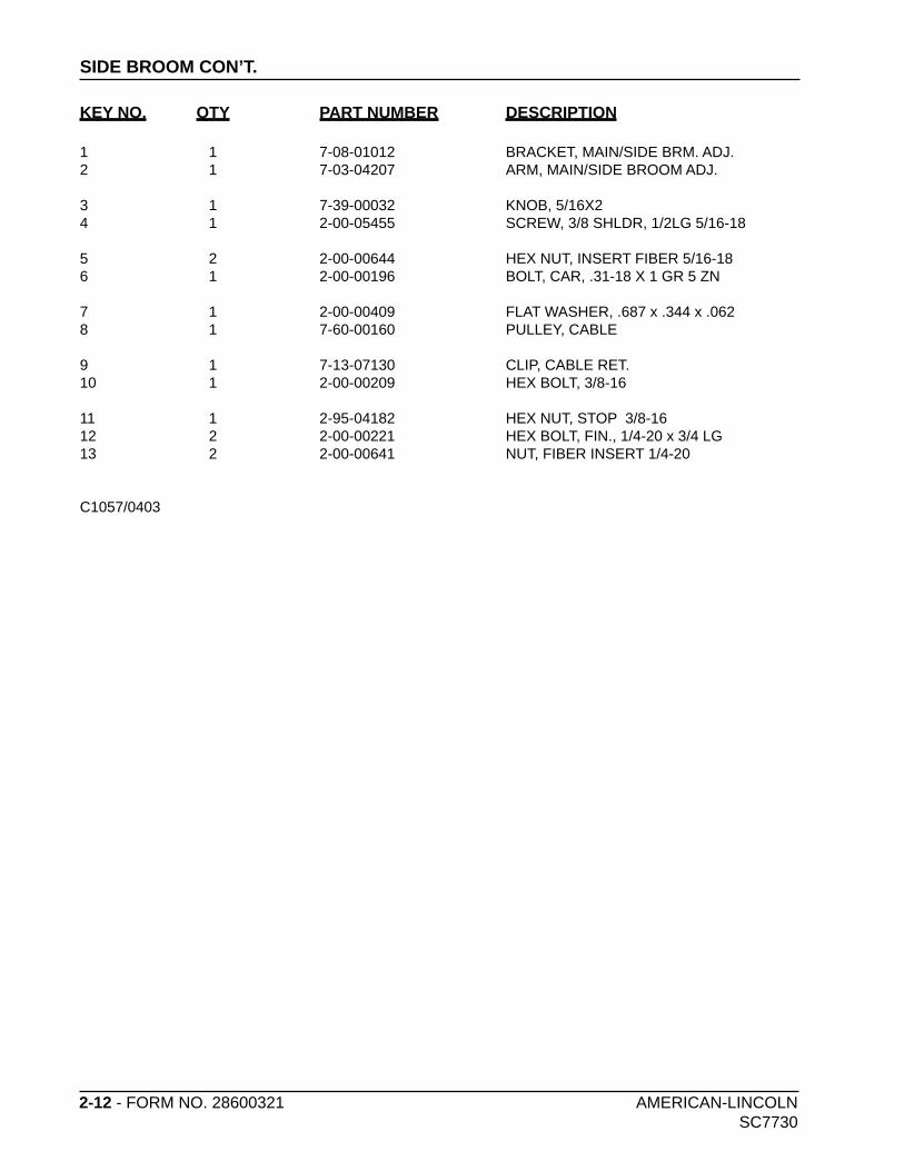
2-12 - FORM NO. 28600321 AMERICAN-LINCOLN SC7730
SIDE BROOM CON’T.
KEY NO. QTY PART NUMBER DESCRIPTION
1 1 7-08-01012 BRACKET, MAIN/SIDE BRM. ADJ.2 1 7-03-04207 ARM, MAIN/SIDE BROOM ADJ.
3 1 7-39-00032 KNOB, 5/16X24 1 2-00-05455 SCREW, 3/8 SHLDR, 1/2LG 5/16-18
5 2 2-00-00644 HEX NUT, INSERT FIBER 5/16-186 1 2-00-00196 BOLT, CAR, .31-18 X 1 GR 5 ZN
7 1 2-00-00409 FLAT WASHER, .687 x .344 x .0628 1 7-60-00160 PULLEY, CABLE
9 1 7-13-07130 CLIP, CABLE RET.10 1 2-00-00209 HEX BOLT, 3/8-16
11 1 2-95-04182 HEX NUT, STOP 3/8-1612 2 2-00-00221 HEX BOLT, FIN., 1/4-20 x 3/4 LG13 2 2-00-00641 NUT, FIBER INSERT 1/4-20
C1057/0403
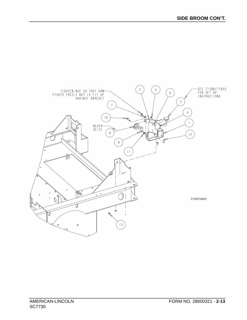
AMERICAN-LINCOLN FORM NO. 28600321 - 2-13SC7730
SIDE BROOM CON’T.
C1057/0403
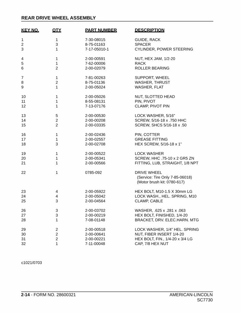
2-14 - FORM NO. 28600321 AMERICAN-LINCOLN SC7730
REAR DRIVE WHEEL ASSEMBLY
KEY NO. QTY PART NUMBER DESCRIPTION
1 1 7-30-08015 GUIDE, RACK2 3 8-75-01163 SPACER3 1 7-17-05010-1 CYLINDER, POWER STEERING
4 1 2-00-00591 NUT, HEX JAM, 1/2-205 1 7-62-00006 RACK6 2 2-00-02079 ROLLER BEARING
7 1 7-81-00263 SUPPORT, WHEEL8 2 8-75-01136 WASHER, THRUST9 1 2-00-05024 WASHER, FLAT
10 1 2-00-05026 NUT, SLOTTED HEAD11 1 8-55-08131 PIN, PIVOT12 1 7-13-07176 CLAMP, PIVOT PIN
13 5 2-00-00530 LOCK WASHER, 5/16”14 2 2-00-00208 SCREW, 5/16-18 x .750 HHC15 2 2-00-03335 SCREW, SHCS 5/16-18 x .50
16 1 2-00-02436 PIN, COTTER17 1 2-00-02557 GREASE FITTING18 3 2-00-02708 HEX SCREW, 5/16-18 x 1”
19 1 2-00-00522 LOCK WASHER20 1 2-00-05341 SCREW, HHC .75-10 x 2 GR5 ZN21 1 2-00-00566 FITTING, LUB, STRAIGHT, 1/8 NPT
22 1 0785-092 DRIVE WHEEL (Service: Tire Only 7-85-06018) (Motor brush kit: 0780-617)
23 4 2-00-05922 HEX BOLT, M10-1.5 X 30mm LG24 4 2-00-05042 LOCK WASH., HEL. SPRING, M1025 3 2-00-04564 CLAMP, CABLE
26 3 2-00-03702 WASHER, .625 x .281 x .06327 3 2-00-00219 HEX BOLT, FINISHED, 1/4-2028 1 7-08-01148 BRACKET, DRV. ELEC.HARN. MTG
29 2 2-00-00518 LOCK WASHER, 1/4” HEL. SPRING30 2 2-00-00641 NUT, FIBER INSERT 1/4-2031 2 2-00-00221 HEX BOLT, FIN., 1/4-20 x 3/4 LG32 1 7-11-00048 CAP, 7/8 HEX NUT
c1021/0703

AMERICAN-LINCOLN FORM NO. 28600321 - 2-15SC7730
C1021/0703
REAR DRIVE WHEEL ASSEMBLY

2-16 - FORM NO. 28600321 AMERICAN-LINCOLN
SC7730
FRONT WHEEL ASSEMBLY
revised 9/07
KEY NO. QTY PART NUMBER DESCRIPTION
1 1 7-03-09014 Axle, Front Wheels
2 1 7-08-02007 Brake Disc
3 4 2-00-04621 Brg, Outer Race (Cup Only)
4 2 2-00-00776 Cotter Pin (1/8 Dia X 1-1/2 Lg.)
5 2 7-89-08044 Wheel, Front Molded 16” Dia
6 2 8-11-00030 Grease Cap
7 2 2-00-00228 Screw, 5/16-18 X 2.50 Hex
8 2 7-33-09027 Hub, Front Wheel
9 2 2-00-03829 Lock Washer, 3/8 Int/Ext Tooth
10# Intentionally Omitted
11 2 8-23-03056 Nut, Special
12 10 8-23-03065 Nut, Wheel
13 5 2-00-03051 Screw, Shcs 1/4-20 X .75
14# 1 56416517 Strap, Static
15 10 8-80-05036 Stud
16 3 2-00-01803 Washer, .328 X 1.06 X .06
17 2 8-75-01136 Thrust Washer
18 2 2-00-02079 Bearing, Roller
19 2 2-00-04622 Bearing (Unsealed)
20 2 2-00-03797 Axle Spacer Washer
21# 1 2-00-03266 Fan Washer
22# 1 2-95-04182 Nut, Hex Stop, 3/8-16
# = Revised or new since last update
71803/8-06

AMERICAN-LINCOLN FORM NO. 28600321 - 2-17
SC7730
FRONT WHEEL ASSEMBLY
revised 9/07
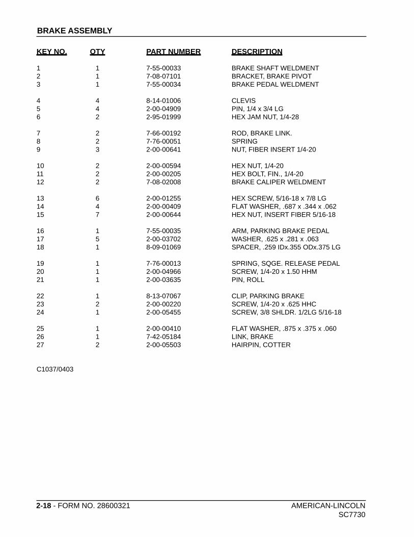
2-18 - FORM NO. 28600321 AMERICAN-LINCOLN SC7730
BRAKE ASSEMBLY
KEY NO. QTY PART NUMBER DESCRIPTION
1 1 7-55-00033 BRAKE SHAFT WELDMENT2 1 7-08-07101 BRACKET, BRAKE PIVOT3 1 7-55-00034 BRAKE PEDAL WELDMENT
4 4 8-14-01006 CLEVIS5 4 2-00-04909 PIN, 1/4 x 3/4 LG6 2 2-95-01999 HEX JAM NUT, 1/4-28
7 2 7-66-00192 ROD, BRAKE LINK.8 2 7-76-00051 SPRING9 3 2-00-00641 NUT, FIBER INSERT 1/4-20
10 2 2-00-00594 HEX NUT, 1/4-2011 2 2-00-00205 HEX BOLT, FIN., 1/4-2012 2 7-08-02008 BRAKE CALIPER WELDMENT
13 6 2-00-01255 HEX SCREW, 5/16-18 x 7/8 LG14 4 2-00-00409 FLAT WASHER, .687 x .344 x .06215 7 2-00-00644 HEX NUT, INSERT FIBER 5/16-18
16 1 7-55-00035 ARM, PARKING BRAKE PEDAL17 5 2-00-03702 WASHER, .625 x .281 x .06318 1 8-09-01069 SPACER, .259 IDx.355 ODx.375 LG 19 1 7-76-00013 SPRING, SQGE. RELEASE PEDAL20 1 2-00-04966 SCREW, 1/4-20 x 1.50 HHM21 1 2-00-03635 PIN, ROLL
22 1 8-13-07067 CLIP, PARKING BRAKE23 2 2-00-00220 SCREW, 1/4-20 x .625 HHC24 1 2-00-05455 SCREW, 3/8 SHLDR. 1/2LG 5/16-18
25 1 2-00-00410 FLAT WASHER, .875 x .375 x .06026 1 7-42-05184 LINK, BRAKE27 2 2-00-05503 HAIRPIN, COTTER
C1037/0403

AMERICAN-LINCOLN FORM NO. 28600321 - 2-19SC7730
C1037/0403
BRAKE ASSEMBLY
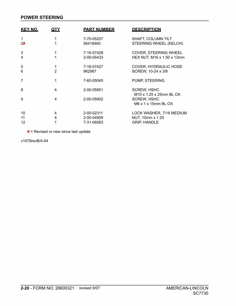
2-20 - FORM NO. 28600321 AMERICAN-LINCOLN
SC7730
POWER STEERING
KEY NO. QTY PART NUMBER DESCRIPTION
1 1 7-70-05207 SHAFT, COLUMN TILT
2# 1 56418460 STEERING WHEEL (KELCH)
3 1 7-16-07428 COVER, STEERING WHEEL
4 1 2-00-05433 HEX NUT, M16 x 1.50 x 13mm
5 1 7-16-07427 COVER, HYDRAULIC HOSE
6 2 962987 SCREW, 10-24 x 3/8
7 1 7-60-05045 PUMP, STEERING
8 4 2-00-05901 SCREW, HSHC
M10 x 1.25 x 25mm BL OX
9 4 2-00-05902 SCREW, HSHC
M6 x 1 x 15mm BL OX
10 4 2-00-02311 LOCK WASHER, 7/16 MEDIUM
11 4 2-00-04959 NUT, 10mm x 1.25
12 1 7-31-06083 GRIP, HANDLE
# = Revised or new since last update
c1078revB/4-04
revised 9/07

AMERICAN-LINCOLN FORM NO. 28600321 - 2-21SC7730
POWER STEERING
C1078revB
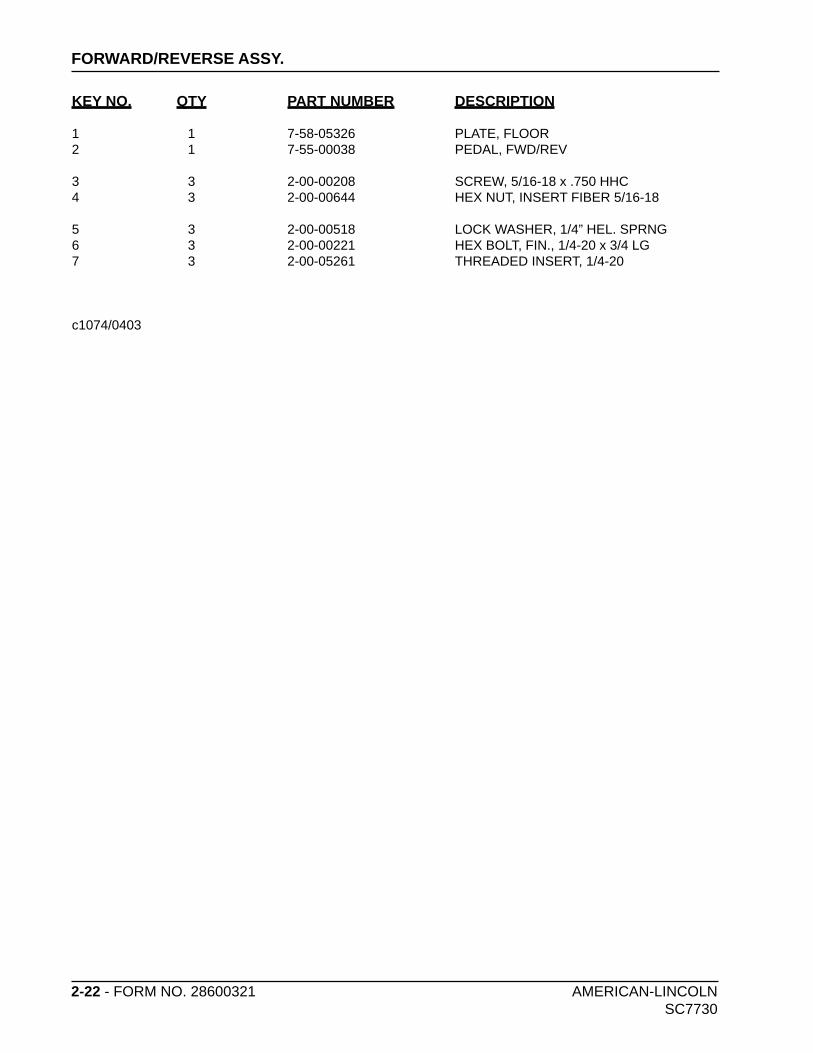
2-22 - FORM NO. 28600321 AMERICAN-LINCOLN SC7730
FORWARD/REVERSE ASSY.
KEY NO. QTY PART NUMBER DESCRIPTION
1 1 7-58-05326 PLATE, FLOOR2 1 7-55-00038 PEDAL, FWD/REV
3 3 2-00-00208 SCREW, 5/16-18 x .750 HHC4 3 2-00-00644 HEX NUT, INSERT FIBER 5/16-18
5 3 2-00-00518 LOCK WASHER, 1/4” HEL. SPRNG 6 3 2-00-00221 HEX BOLT, FIN., 1/4-20 x 3/4 LG7 3 2-00-05261 THREADED INSERT, 1/4-20
c1074/0403
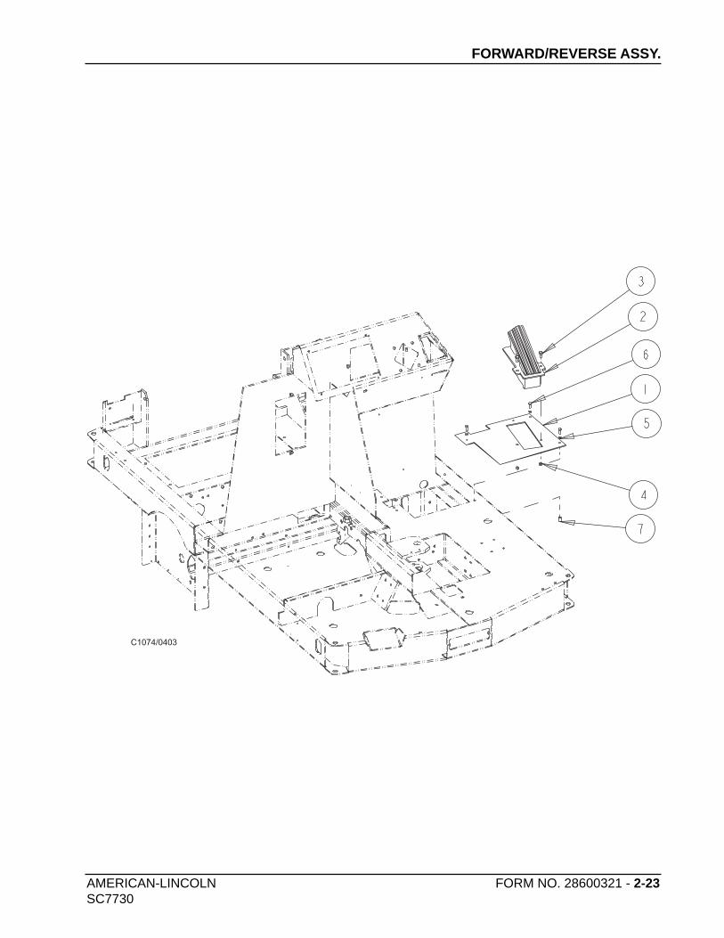
AMERICAN-LINCOLN FORM NO. 28600321 - 2-23SC7730
FORWARD/REVERSE ASSY.
C1074/0403

2-24 - FORM NO. 28600321 AMERICAN-LINCOLN SC7730
SOLUTION CONTROL
KEY NO. QTY PART NUMBER DESCRIPTION
1 1 7-88-00073 VALVE, SOLUTION (36VDC)2 2 2-00-00221 HEX BOLT, FIN., 1/4-20 x 3/4 LG
3 2 2-00-00641 NUT, FIBER INSERT 1/4-204 1 7-33-02483 HOSE, 3/4” ID HEATER x 16” LG
5 1 7-33-02410 HOSE, SOLUTION FEED, 22” LG6 4 2-00-03407 CLAMP, HOSE, WITTECK #10P
c1075/0403
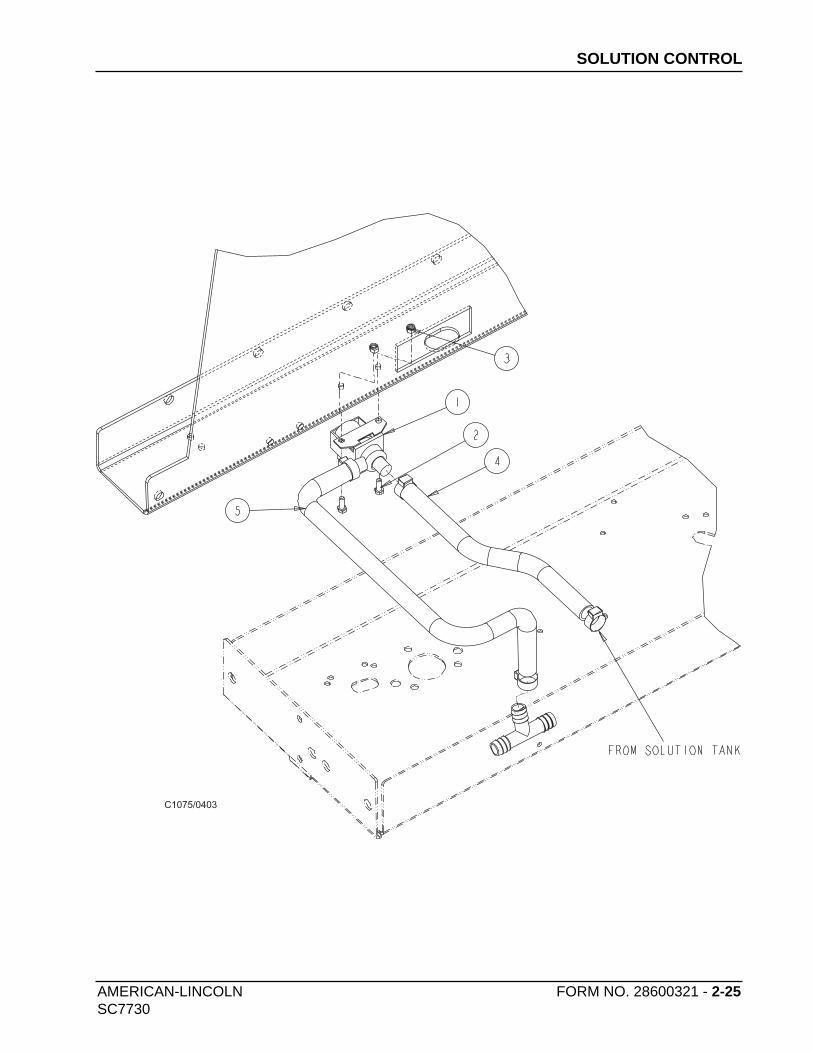
AMERICAN-LINCOLN FORM NO. 28600321 - 2-25SC7730
SOLUTION CONTROL
C1075/0403
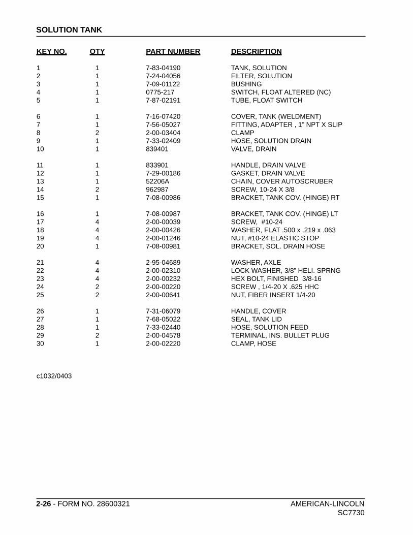
2-26 - FORM NO. 28600321 AMERICAN-LINCOLN SC7730
SOLUTION TANK
KEY NO. QTY PART NUMBER DESCRIPTION
1 1 7-83-04190 TANK, SOLUTION2 1 7-24-04056 FILTER, SOLUTION3 1 7-09-01122 BUSHING4 1 0775-217 SWITCH, FLOAT ALTERED (NC)5 1 7-87-02191 TUBE, FLOAT SWITCH
6 1 7-16-07420 COVER, TANK (WELDMENT)7 1 7-56-05027 FITTING, ADAPTER , 1” NPT X SLIP8 2 2-00-03404 CLAMP9 1 7-33-02409 HOSE, SOLUTION DRAIN10 1 839401 VALVE, DRAIN
11 1 833901 HANDLE, DRAIN VALVE12 1 7-29-00186 GASKET, DRAIN VALVE13 1 52206A CHAIN, COVER AUTOSCRUBER14 2 962987 SCREW, 10-24 X 3/815 1 7-08-00986 BRACKET, TANK COV. (HINGE) RT
16 1 7-08-00987 BRACKET, TANK COV. (HINGE) LT17 4 2-00-00039 SCREW, #10-2418 4 2-00-00426 WASHER, FLAT .500 x .219 x .06319 4 2-00-01246 NUT, #10-24 ELASTIC STOP20 1 7-08-00981 BRACKET, SOL. DRAIN HOSE
21 4 2-95-04689 WASHER, AXLE22 4 2-00-02310 LOCK WASHER, 3/8” HELI. SPRNG23 4 2-00-00232 HEX BOLT, FINISHED 3/8-1624 2 2-00-00220 SCREW , 1/4-20 X .625 HHC25 2 2-00-00641 NUT, FIBER INSERT 1/4-20
26 1 7-31-06079 HANDLE, COVER27 1 7-68-05022 SEAL, TANK LID28 1 7-33-02440 HOSE, SOLUTION FEED29 2 2-00-04578 TERMINAL, INS. BULLET PLUG30 1 2-00-02220 CLAMP, HOSE
c1032/0403

AMERICAN-LINCOLN FORM NO. 28600321 - 2-27SC7730
SOLUTION TANK
C1032/0403

2-28 - FORM NO. 28600321 AMERICAN-LINCOLN SC7730
RECOVERY TANK
KEY NO. QTY PART NUMBER DESCRIPTION
1* 1 7-83-04178-1 TANK, RECOVERY2 1 7-33-02590 HOSE ASSY., DRAIN3 1 7-19-08077 DOOR, REC. TANK DRAIN4 1 7-29-00250 GASKET, REC. TANK DRAIN5 2 7-80-05086 STUD, CLEANOUT DOOR
6 2 2-00-00410 FLAT WASHER, .875 x .375 x .060 7 2 25201A KNOB8 3 2-95-04689 WASHER, AXLE9 3 2-00-02310 LOCK WASHER, 3/8”HEL. SPRNG10 3 2-00-00232 HEX BOLT, FINISHED, 3/8-16 11 1 7-29-00265 GASKET, VAC RECOVERY12 1 0775-164 SWITCH (GRAY), FLOAT13 1 7-09-01122 BUSHING14 1 7-58-05299 PLATE, VAC. INLET (WELDED)15 1 7-10-04008 CAGE, FLOAT
16 1 7-26-04012 FLOAT, RECOVERY 17 4 2-00-00466 FLAT WASHER, .625 x .203 x .03118 4 2-00-03940 SCREW, T/C HH #10-24 x .50 LG19 1 7-33-02397 HOSE, SQUEEGEE20 1 7-87-02203 COUPLING
21 1 7-33-02420 HOSE, TANK SQUEEGEE22 4 2-00-02216 CLAMP, HOSE23 1 7-33-02427 HOSE, REC. TANK INLET24 4 2-14-03197 WASHR, NEOPRENE, 1 x .19 x 1/825 4 2-00-05237 FLAT WASHR, 1.063 x .265 x .063
26 2 2-00-04687 LOCK WASHER, 1/4” HEL. SPRNG27 2 2-00-04688 HEX NUT, 1/4-2028 2 2-00-04966 SCREW, 1/4-20 x 1.50 HHM
29 1 7-25-02033 PLUG, HOSE30 1 2-00-03466 SCREW , #10-16 x 1/231 2 7-31-07032 HANGER, DRAIN HOSE32 4 2-00-04876 SCREW, 1/4-20 x .50 BHCS W/NYLOK33 8 2-00-01994 SCREW, #8-15 x 3/4 LG, TF/PRH34 4 7-29-00281 GASKET35 4 2-00-03702 WASHER, .625 x .281 x .063
*IF REPLACING ITEM #1, YOU MUST ALSO ORDER: 1 OF 8-18-00537 (7730 DECAL) 1 OF 8-18-00524 (AMERICAN-LINCOLN LOGO DECAL) (REFERENCE PAGE 2-80 THRU 2-83 FOR PLACE MENT)
c1031/0403

AMERICAN-LINCOLN FORM NO. 28600321 - 2-29SC7730
RECOVERY TANK
C1031/0403

2-30 - FORM NO. 28600321 AMERICAN-LINCOLN SC7730
SCRUB DECK (40”)
KEY NO. QTY PART NUMBER DESCRIPTION
1 1 7-27-07202 FRAME, BRUSH DRIVE (40”)2 6 2-00-00596 HEX NUT,1/2-13 x .44 LG3 2 0760-542 MOTOR & REDUCER ASSY. (Motor brush kit: 0780-582)
4 2 2-00-03463 KEY - 1/4 SQ. x 2.63 STEEL5 2 7-33-09042 HUB, BRUSH DRIVE6 6 2-00-00402 WASHER, 25/64” ID x 3/4” OD
7 6 2-00-00209 HEX BOLT, 3/8-168 2 7-03-04123 ARM, BRUSH DRIVE (WELDMENT)9 2 7-41-00027 LATCH, BRUSH DRIVER
10 2 2-00-00641 NUT, FIBER INSERT 1/4-2011 2 2-00-00221 HEX BOLT, FIN., 1/4-20 x 3/4 LG12 4 2-00-04851 WASHER, ENGINE MOUNT
13 2 2-00-00530 LOCK WASHER, 5/16”14 2 2-00-00218 HEX BOLT, 5/16-1815 6 2-00-02310 LOCK WASHER, 3/8” HEL. SPRING
16 2 7-55-08151 PIN, LOCK UP17 REF 0765-271 SCRUB BRUSH ASSY.
c1072/0403
revised 9/06

AMERICAN-LINCOLN FORM NO. 28600321 - 2-31SC7730
SCRUB DECK (40”)
C1072/0403

2-32 - FORM NO. 28600321 AMERICAN-LINCOLN SC7730
SCRUB DECK LIFT (40”)
KEY NO. QTY PART NUMBER DESCRIPTION
1 1 7-08-01029 BRACKET (RH), FRAME TO SCRUB DECK LIFT2 2 2-00-05505 BEARING, THRUST, PLAIN, BRONZE, 1/2 ID x 1.0 OD 3 2 7-42-05172 ARM, LOWER SCRUB DECK LIFT
4 1 7-08-01030 BRACKET (LH), FRAME TO SCRUB DECK LIFT5 8 2-00-00456 FLAT WASHER, .812x.406x.063 S/S6 2 2-00-00646 LOCK NUT, ELASTIC, 5/16-18
7 2 2-00-05506 BEARING, FLANGED, PLAIN, BRONZE, 1/2 ID x 3/4 OD8 4 2-00-00402 WASHER, 25/64 ID x 3/4 OD9 4 2-00-00233 HEX BOLT, FIN., 3/8-16 x 1.00
10 4 2-95-04182 NUT, HEX STOP, 3/8-1611 2 2-00-05507 PIN, CLEVIS, 3/8 DIA x 1.0 LG12 4 2-00-05503 HAIRPIN, COTTER
13 2 2-00-05508 PIN, CLEVIS, 3/8 DIA x 1-5/16 LG14 1 7-70-05197 SHAFT, 40” SD LIFT (WELDMENT)15 1 7-17-05025 CYLINDER, HYD., SD LIFT
16 2 7-13-07222 CLAMP, SHAFT SUPPORT, SD LIFT17 2 2-00-02587 SCREW (CAP), HEX, .25-20 x 1.2518 2 2-00-00641 NUT, FIBER INSERT 1/4-20
19 1 2-00-05501 BEARING, PLAIN SLEEVE, BRONZE, 1/2 ID x 5/8 OD 20 1 2-00-05500 PIN, CLEVIS, 1/2 DIA x 1-27/64 LG21 2 2-00-05320 HAIRPIN, COTTER
22 1 2-00-05510 PIN, CLEVIS, 1/2 DIA x 4-1/2 LG23 1 2-00-00405 FLAT WASHER, 1.063 x .531 x .09424 2 2-00-05504 SCREW-SHOULDER, 5/16-18 X 5/8, HEX SOCKET HD
71808_1
revised 9/06

AMERICAN-LINCOLN FORM NO. 28600321 - 2-33SC7730
SCRUB DECK LIFT (40”)
revised 9/06
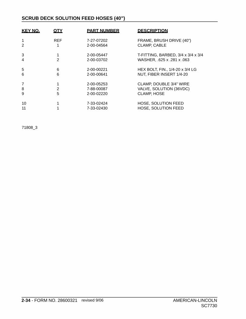
2-34 - FORM NO. 28600321 AMERICAN-LINCOLN SC7730
SCRUB DECK SOLUTION FEED HOSES (40”)
KEY NO. QTY PART NUMBER DESCRIPTION
1 REF 7-27-07202 FRAME, BRUSH DRIVE (40”)2 1 2-00-04564 CLAMP, CABLE
3 1 2-00-05447 T-FITTING, BARBED, 3/4 x 3/4 x 3/4 4 2 2-00-03702 WASHER, .625 x .281 x .063
5 6 2-00-00221 HEX BOLT, FIN., 1/4-20 x 3/4 LG6 6 2-00-00641 NUT, FIBER INSERT 1/4-20
7 1 2-00-05253 CLAMP, DOUBLE 3/4” WIRE8 2 7-88-00087 VALVE, SOLUTION (36VDC)9 5 2-00-02220 CLAMP, HOSE
10 1 7-33-02424 HOSE, SOLUTION FEED11 1 7-33-02430 HOSE, SOLUTION FEED
71808_3
revised 9/06

AMERICAN-LINCOLN FORM NO. 28600321 - 2-35SC7730
SCRUB DECK SOLUTION FEED HOSES (40”)
revised 9/06
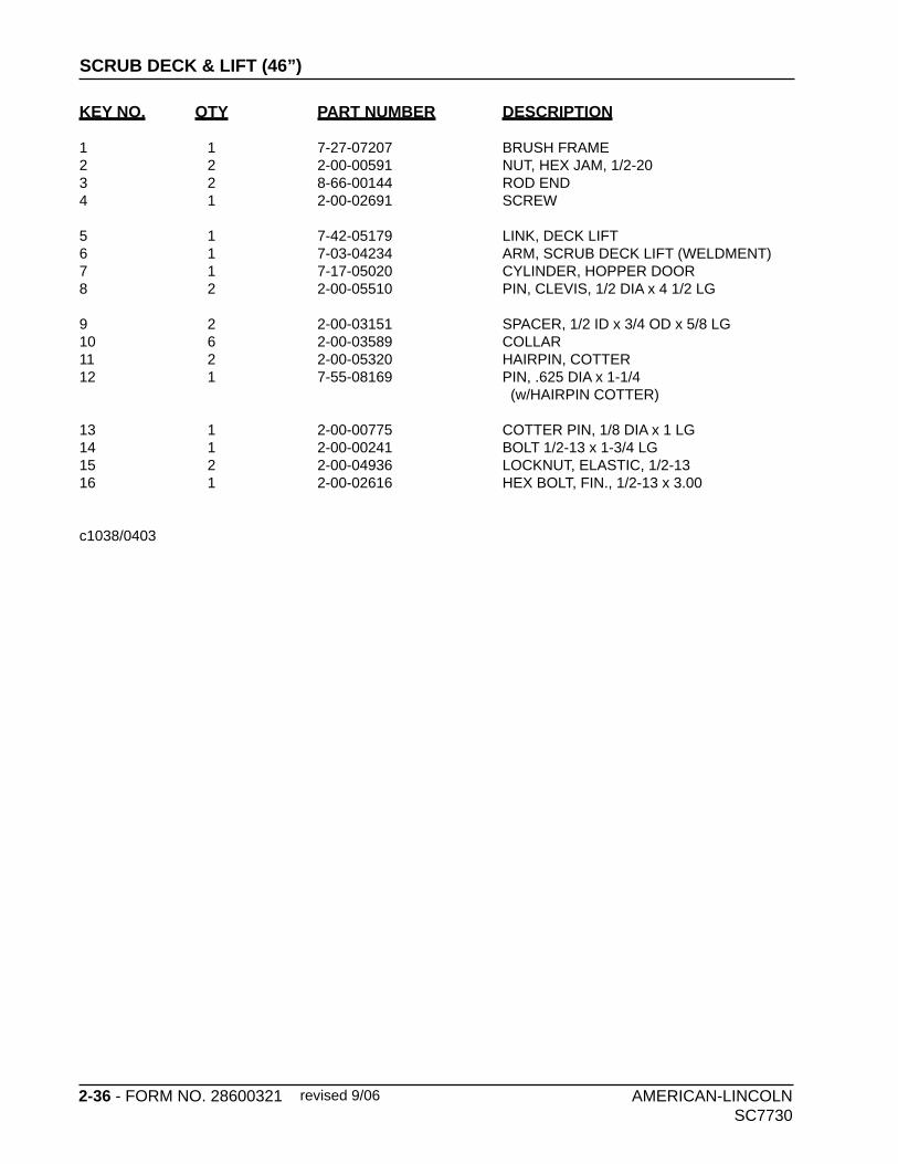
2-36 - FORM NO. 28600321 AMERICAN-LINCOLN SC7730
SCRUB DECK & LIFT (46”)
KEY NO. QTY PART NUMBER DESCRIPTION
1 1 7-27-07207 BRUSH FRAME2 2 2-00-00591 NUT, HEX JAM, 1/2-203 2 8-66-00144 ROD END4 1 2-00-02691 SCREW
5 1 7-42-05179 LINK, DECK LIFT6 1 7-03-04234 ARM, SCRUB DECK LIFT (WELDMENT)7 1 7-17-05020 CYLINDER, HOPPER DOOR8 2 2-00-05510 PIN, CLEVIS, 1/2 DIA x 4 1/2 LG
9 2 2-00-03151 SPACER, 1/2 ID x 3/4 OD x 5/8 LG10 6 2-00-03589 COLLAR11 2 2-00-05320 HAIRPIN, COTTER12 1 7-55-08169 PIN, .625 DIA x 1-1/4 (w/HAIRPIN COTTER)
13 1 2-00-00775 COTTER PIN, 1/8 DIA x 1 LG14 1 2-00-00241 BOLT 1/2-13 x 1-3/4 LG15 2 2-00-04936 LOCKNUT, ELASTIC, 1/2-1316 1 2-00-02616 HEX BOLT, FIN., 1/2-13 x 3.00
c1038/0403
revised 9/06

AMERICAN-LINCOLN FORM NO. 28600321 - 2-37SC7730
C1038/0403
SCRUB DECK & LIFT (46”)
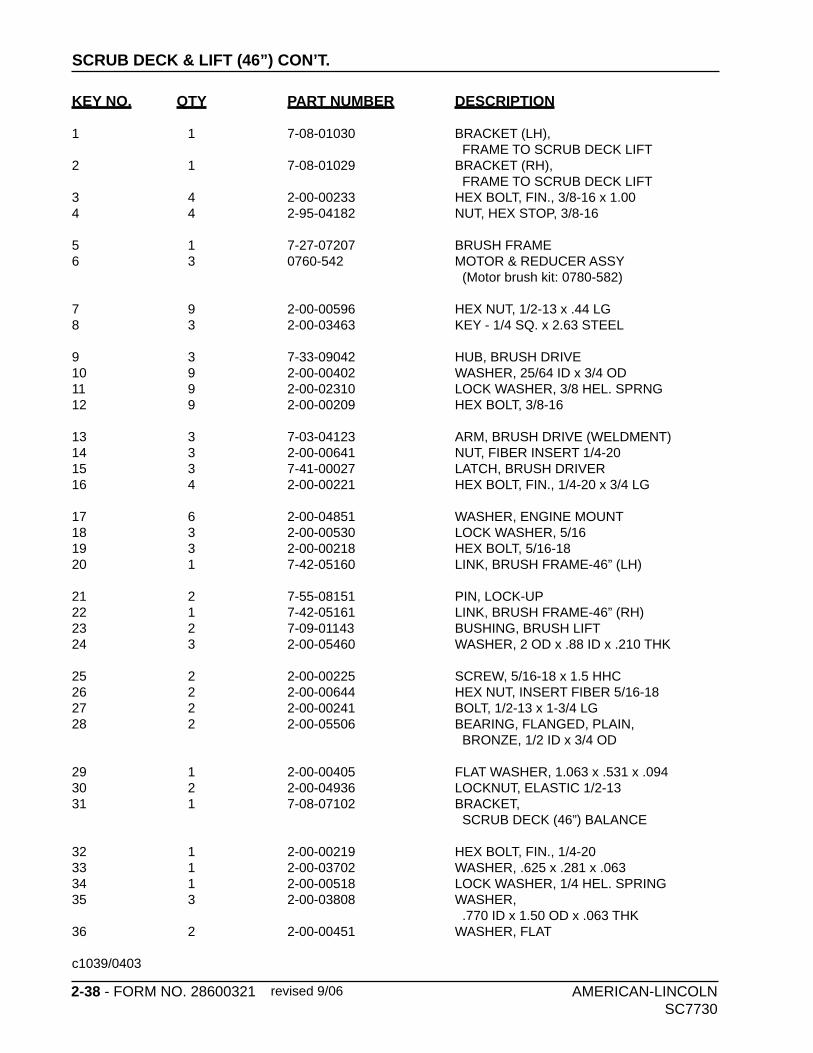
2-38 - FORM NO. 28600321 AMERICAN-LINCOLN SC7730
SCRUB DECK & LIFT (46”) CON’T.
KEY NO. QTY PART NUMBER DESCRIPTION
1 1 7-08-01030 BRACKET (LH), FRAME TO SCRUB DECK LIFT2 1 7-08-01029 BRACKET (RH), FRAME TO SCRUB DECK LIFT3 4 2-00-00233 HEX BOLT, FIN., 3/8-16 x 1.004 4 2-95-04182 NUT, HEX STOP, 3/8-16
5 1 7-27-07207 BRUSH FRAME6 3 0760-542 MOTOR & REDUCER ASSY (Motor brush kit: 0780-582)
7 9 2-00-00596 HEX NUT, 1/2-13 x .44 LG8 3 2-00-03463 KEY - 1/4 SQ. x 2.63 STEEL
9 3 7-33-09042 HUB, BRUSH DRIVE10 9 2-00-00402 WASHER, 25/64 ID x 3/4 OD11 9 2-00-02310 LOCK WASHER, 3/8 HEL. SPRNG12 9 2-00-00209 HEX BOLT, 3/8-16
13 3 7-03-04123 ARM, BRUSH DRIVE (WELDMENT)14 3 2-00-00641 NUT, FIBER INSERT 1/4-2015 3 7-41-00027 LATCH, BRUSH DRIVER16 4 2-00-00221 HEX BOLT, FIN., 1/4-20 x 3/4 LG
17 6 2-00-04851 WASHER, ENGINE MOUNT18 3 2-00-00530 LOCK WASHER, 5/1619 3 2-00-00218 HEX BOLT, 5/16-1820 1 7-42-05160 LINK, BRUSH FRAME-46” (LH)
21 2 7-55-08151 PIN, LOCK-UP22 1 7-42-05161 LINK, BRUSH FRAME-46” (RH) 23 2 7-09-01143 BUSHING, BRUSH LIFT24 3 2-00-05460 WASHER, 2 OD x .88 ID x .210 THK
25 2 2-00-00225 SCREW, 5/16-18 x 1.5 HHC 26 2 2-00-00644 HEX NUT, INSERT FIBER 5/16-18 27 2 2-00-00241 BOLT, 1/2-13 x 1-3/4 LG 28 2 2-00-05506 BEARING, FLANGED, PLAIN, BRONZE, 1/2 ID x 3/4 OD
29 1 2-00-00405 FLAT WASHER, 1.063 x .531 x .094 30 2 2-00-04936 LOCKNUT, ELASTIC 1/2-1331 1 7-08-07102 BRACKET, SCRUB DECK (46”) BALANCE
32 1 2-00-00219 HEX BOLT, FIN., 1/4-2033 1 2-00-03702 WASHER, .625 x .281 x .06334 1 2-00-00518 LOCK WASHER, 1/4 HEL. SPRING35 3 2-00-03808 WASHER, .770 ID x 1.50 OD x .063 THK 36 2 2-00-00451 WASHER, FLAT
c1039/0403
revised 9/06

AMERICAN-LINCOLN FORM NO. 28600321 - 2-39SC7730
SCRUB DECK & LIFT (46”) CON’T.
revised 9/06

2-40 - FORM NO. 28600321 AMERICAN-LINCOLN SC7730
SCRUB DECK & LIFT/HOSES (46”) CON’T.
KEY NO. QTY PART NUMBER DESCRIPTION
1 REF 7-27-07207 FRAME, BRUSH2 1 7-48-00049 WELDMENT, WATER MANIFOLD
3 8 2-00-00221 HEX BOLT, FIN., 1/4-20 x 3/4 LG 4 3 7-88-00087 VALVE, SOLUTION (36VDC)
5 7 2-00-03407 CLAMP, HOSE (WITTECK #10P) 6 8 2-00-00641 NUT, FIBER INSERT 1/4-20
7 1 7-33-02593 HOSE, SOLUTION FEED (5/6 ID x 6.25 LG)
8 1 7-33-02594 HOSE, SOLUTION FEED (5/8 ID x 12.75 LG HEATER HOSE)
9 1 7-33-02595 HOSE, SOLUTION FEED (5/8 ID x 23.5 LG HEATER HOSE)
10 1 7-33-02434 HOSE, HEATER, 3/4 x 2 LG11 1 2-00-05380 FITTING, ELBOW
c1040/0403

AMERICAN-LINCOLN FORM NO. 28600321 - 2-41SC7730
C1040/0403
SCRUB DECK & LIFT/HOSES (46”) CON’T.
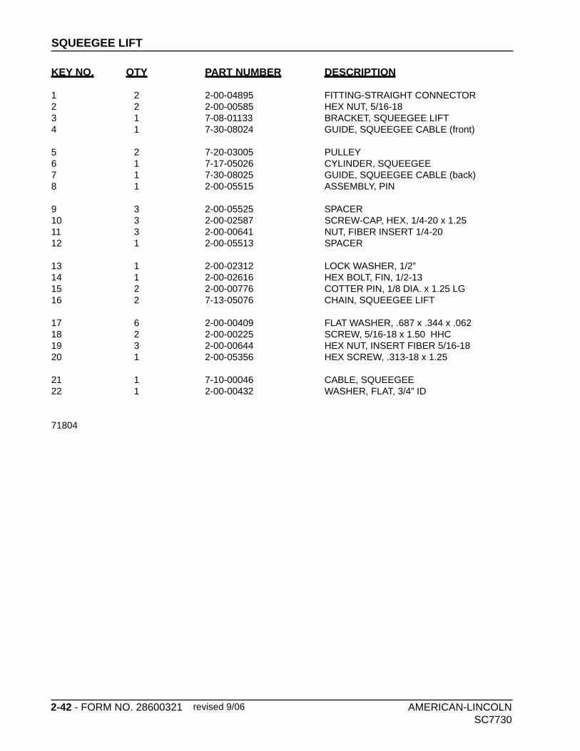
2-42 - FORM NO. 28600321 AMERICAN-LINCOLN SC7730
SQUEEGEE LIFT
KEY NO. QTY PART NUMBER DESCRIPTION
1 2 2-00-04895 FITTING-STRAIGHT CONNECTOR2 2 2-00-00585 HEX NUT, 5/16-183 1 7-08-01133 BRACKET, SQUEEGEE LIFT4 1 7-30-08024 GUIDE, SQUEEGEE CABLE (front)
5 2 7-20-03005 PULLEY6 1 7-17-05026 CYLINDER, SQUEEGEE7 1 7-30-08025 GUIDE, SQUEEGEE CABLE (back)8 1 2-00-05515 ASSEMBLY, PIN
9 3 2-00-05525 SPACER10 3 2-00-02587 SCREW-CAP, HEX, 1/4-20 x 1.2511 3 2-00-00641 NUT, FIBER INSERT 1/4-2012 1 2-00-05513 SPACER
13 1 2-00-02312 LOCK WASHER, 1/2”14 1 2-00-02616 HEX BOLT, FIN, 1/2-1315 2 2-00-00776 COTTER PIN, 1/8 DIA. x 1.25 LG16 2 7-13-05076 CHAIN, SQUEEGEE LIFT
17 6 2-00-00409 FLAT WASHER, .687 x .344 x .06218 2 2-00-00225 SCREW, 5/16-18 x 1.50 HHC19 3 2-00-00644 HEX NUT, INSERT FIBER 5/16-1820 1 2-00-05356 HEX SCREW, .313-18 x 1.25
21 1 7-10-00046 CABLE, SQUEEGEE22 1 2-00-00432 WASHER, FLAT, 3/4” ID
71804
revised 9/06

AMERICAN-LINCOLN FORM NO. 28600321 - 2-43SC7730
SQUEEGEE LIFT
revised 9/06

2-44 - FORM NO. 28600321 AMERICAN-LINCOLN SC7730
REAR SQUEEGEE (40”)
KEY NO. QTY PART NUMBER DESCRIPTION
1 2 2-00-05343 CARRIAGE BOLT, 3/8-16 x 4”2 2 2-00-00216 HEX BOLT, 3/8-16 x 2”3 2 2-00-05344 HEX BOLT, 5/16-18 X 1.75”
4 2 7-75-01164 BUSHING, SPACER5 2 7-89-08073 CASTER6 1 7-13-07188 CLAMP, LH SQUEEGEE END,
7 1 7-13-07187 CLAMP, RH SQUEEGEE END,8 1 7-20-06010 DUCT, SQUEEGEE INLET9 4 7-39-00026 KNOB, SQUEEGEE
10 2 7-13-07156 NUT, CLAMP11 2 2-00-02360 HEX NUT, 3/8-1612 2 2-00-00615 HEX NUT, 5/8-11
13 2 2-00-04962 O-RING14 2 2-00-03842 PIN, ROLL 1/4 X 115 1 7-77-00110 SQUEEGEE, INNER (RUBBER)
16 2 7-75-01188 SPACER, SQUEEGEE17 1 7-77-00109 SQUEEGEE, OUTER (RUBBER)18 1 7-86-08064 SQUEEGEE WELDMENT (40”)
19 1 7-79-00101 STRAP, SQUEEGEE CLAMP (40”)20 6 2-00-00402 WASHER, 25/64” ID x 3/4” OD21 2 2-14-00184 WHEEL
71366
revised 9/06

AMERICAN-LINCOLN FORM NO. 28600321 - 2-45SC7730
REAR SQUEEGEE (40”)
revised 9/06

2-46 - FORM NO. 28600321 AMERICAN-LINCOLN SC7730
REAR SQUEEGEE (46”)
KEY NO. QTY PART NUMBER DESCRIPTION
1 2 7-75-01164 BUSHING, SPACER2 2 7-89-08073 CASTER3 2 7-13-07157 CLAMP, SQUEEGEE END
4 2 7-13-07156 CLAMP, NUT5 1 7-20-06010 DUCT, SQUEEGEE INLET6 4 7-39-00026 KNOB, SQUEEGEE
7 2 2-00-04962 O-RING8 1 7-77-00110 SQUEEGEE, INNER (RUBBER)9 2 7-75-01169 SPACER, SQUEEGEE
10 1 7-77-00109 SQUEEGEE, OUTER (RUBBER)11 1 7-86-08038 SQUEEGEE WELDMENT12 1 7-79-00088 STRAP, SQUEEGEE CLAMP
13 2 2-14-00184 WHEEL14 2 2-00-00216 SCREW, 3/8-16 x 2.0 HHC15 4 2-00-00402 FLAT WASHER, .75 x .390 x .0944
16 2 2-00-02360 HEX NUT, 3/8-1617 2 2-00-05344 SCREW, HHM .313-18 x 1.75 SS18 2 2-00-05343 CARRIAGE BOLT, .38-16 x 3.50 SS
c1081/0403

AMERICAN-LINCOLN FORM NO. 28600321 - 2-47SC7730
9
10
3
4
12
18
5
1
11
2
8
7
13
6
14
15
16
17
C1081/0403
REAR SQUEEGEE (46”)
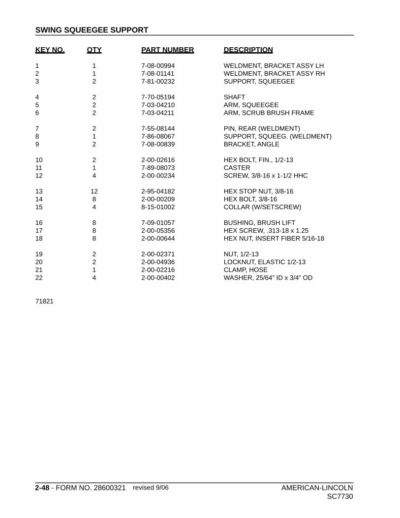
2-48 - FORM NO. 28600321 AMERICAN-LINCOLN SC7730
SWING SQUEEGEE SUPPORT
KEY NO. QTY PART NUMBER DESCRIPTION
1 1 7-08-00994 WELDMENT, BRACKET ASSY LH2 1 7-08-01141 WELDMENT, BRACKET ASSY RH3 2 7-81-00232 SUPPORT, SQUEEGEE
4 2 7-70-05194 SHAFT5 2 7-03-04210 ARM, SQUEEGEE6 2 7-03-04211 ARM, SCRUB BRUSH FRAME
7 2 7-55-08144 PIN, REAR (WELDMENT)8 1 7-86-08067 SUPPORT, SQUEEG. (WELDMENT)9 2 7-08-00839 BRACKET, ANGLE
10 2 2-00-02616 HEX BOLT, FIN., 1/2-1311 1 7-89-08073 CASTER 12 4 2-00-00234 SCREW, 3/8-16 x 1-1/2 HHC
13 12 2-95-04182 HEX STOP NUT, 3/8-1614 8 2-00-00209 HEX BOLT, 3/8-1615 4 8-15-01002 COLLAR (W/SETSCREW)
16 8 7-09-01057 BUSHING, BRUSH LIFT17 8 2-00-05356 HEX SCREW, .313-18 x 1.2518 8 2-00-00644 HEX NUT, INSERT FIBER 5/16-18
19 2 2-00-02371 NUT, 1/2-1320 2 2-00-04936 LOCKNUT, ELASTIC 1/2-1321 1 2-00-02216 CLAMP, HOSE22 4 2-00-00402 WASHER, 25/64” ID x 3/4” OD
71821
revised 9/06
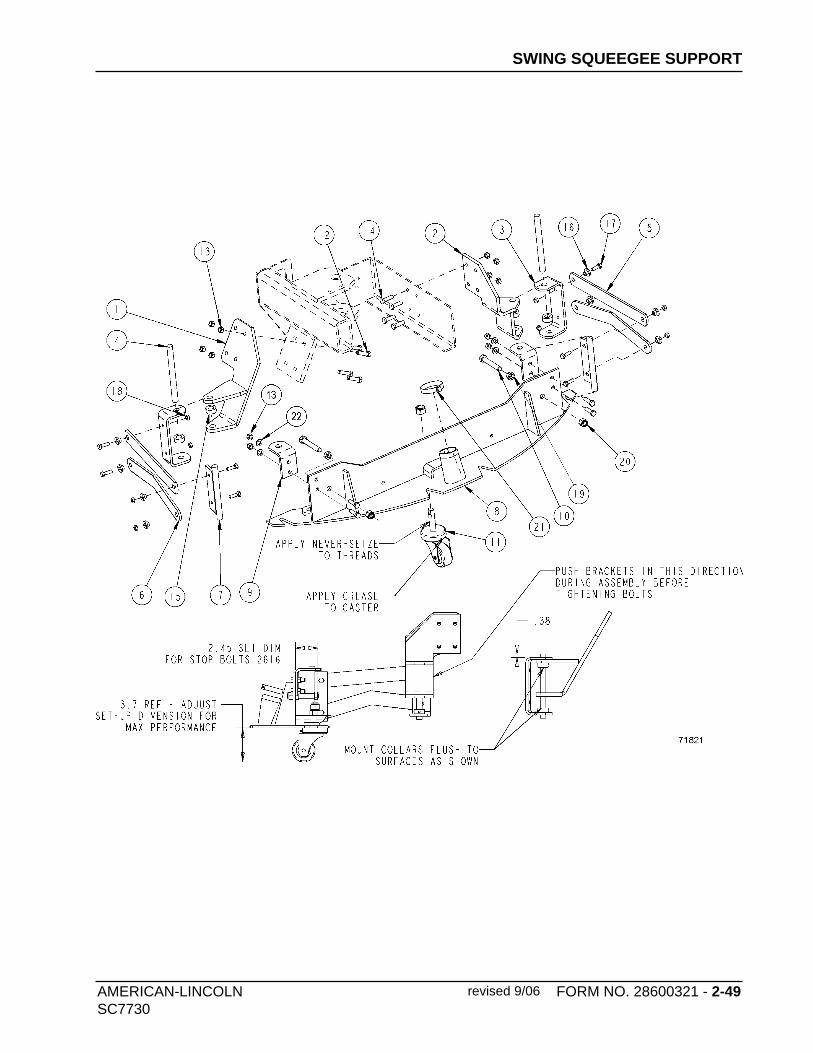
AMERICAN-LINCOLN FORM NO. 28600321 - 2-49SC7730
SWING SQUEEGEE SUPPORT
revised 9/06

2-50 - FORM NO. 28600321 AMERICAN-LINCOLN SC7730
C1055/0403
SIDE SQUEEGEE 40”
KEY NO. QTY PART NUMBER DESCRIPTION
1 1 7-86-08063 TOOL, SIDE SQUEEGEE (LH)2 1 7-86-08062 TOOL, SIDE SQUEEGEE (RH)3 1 7-77-00140 SIDE SQUEEGEE, INNER (rubber)4 1 7-77-00141 SIDE SQUEEGEE, OUTER (rubber)5 2 7-13-07209 CLAMP, SIDE SQUEEGEE6 1 7-77-00140 SIDE SQUEEGEE, INNER (rubber)7 1 7-77-00141 SIDE SQUEEGEE, OUTER (rubber)8 2 7-55-08151 PIN, LOCK-UP9 16 2-00-03702 WASHER, .625 x .281 x .06310 16 2-00-02587 SCREW, 1/4-20 x 1.25 HEX CAP11 16 2-00-00641 NUT, 1/4-20 FIBER INSERT
c1055/0403
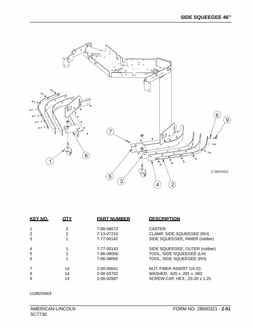
AMERICAN-LINCOLN FORM NO. 28600321 - 2-51SC7730
SIDE SQUEEGEE 46”
1
6
5
7
89
34 2
C1082/0403
KEY NO. QTY PART NUMBER DESCRIPTION
1 2 7-89-08073 CASTER2 2 7-13-07210 CLAMP, SIDE SQUEEGEE (RH)3 1 7-77-00142 SIDE SQUEEGEE, INNER (rubber)
4 1 7-77-00143 SIDE SQUEEGEE, OUTER (rubber)5 1 7-86-08066 TOOL, SIDE SQUEEGEE (LH)6 1 7-86-08065 TOOL, SIDE SQUEEGEE (RH)
7 14 2-00-00641 NUT, FIBER INSERT 1/4-208 14 2-00-03702 WASHER, .625 x .281 x .0639 14 2-00-02587 SCREW-CAP, HEX, .25-20 x 1.25
c1082/0403

2-52 - FORM NO. 28600321 AMERICAN-LINCOLN SC7730
HOPPER ASSEMBLY
revised 9/06
KEY NO. QTY PART NUMBER DESCRIPTION
1 1 0782-130 ACTUATOR, DUMP DOOR (36V)2 1 7-03-04209 ARM, HOPPER SAFETY3 1 2-00-00219 HEX BOLT, FIN., 1/4-20
4 6 2-00-00221 HEX BOLT, FIN., 1/4-20 x 3/4 LG5 1 7-13-07201 CLAMP, HOPPER6 1 7-25-08092 FLAP, HOPPER
7 3 2-00-00405 FLAT WASHER, 1.063 x .531 x .0948 2 7-29-00259 GASKET, HOPPER9 1 7-32-06026 HOPPER, POWER DUMP (WELDMENT)
10 1 2-00-04936 LOCKNUT, ELASTIC 1/2-1311 6 2-00-00641 NUT, FIBER INSERT 1/4-2012 2 2-95-04182 NUT, HEX STOP, 3/8-16
13 1 7-55-08167 PIN, HOPPER SHEAR14 1 2-00-03280 RING, 1/2 RETAINING (E-STYLE)15 2 2-00-05424 SCREW, HEX SOCKET SHOULDER, 3/8-16
16 1 7-76-00121 SPRING, HOPPER SAFETY ARM17 1 7-82-00047 PROXIMITY SWITCH (LOW DUMP HOPPER)18 1 2-00-03702 WASHER, .625 x .281 x .063
19 1 2-00-00224 SCR-HHC .313-18 X .50 GR 5 ZN20 1 2-00-00247 SCREW-HHC .313-18 X 2.25
c1033/0403
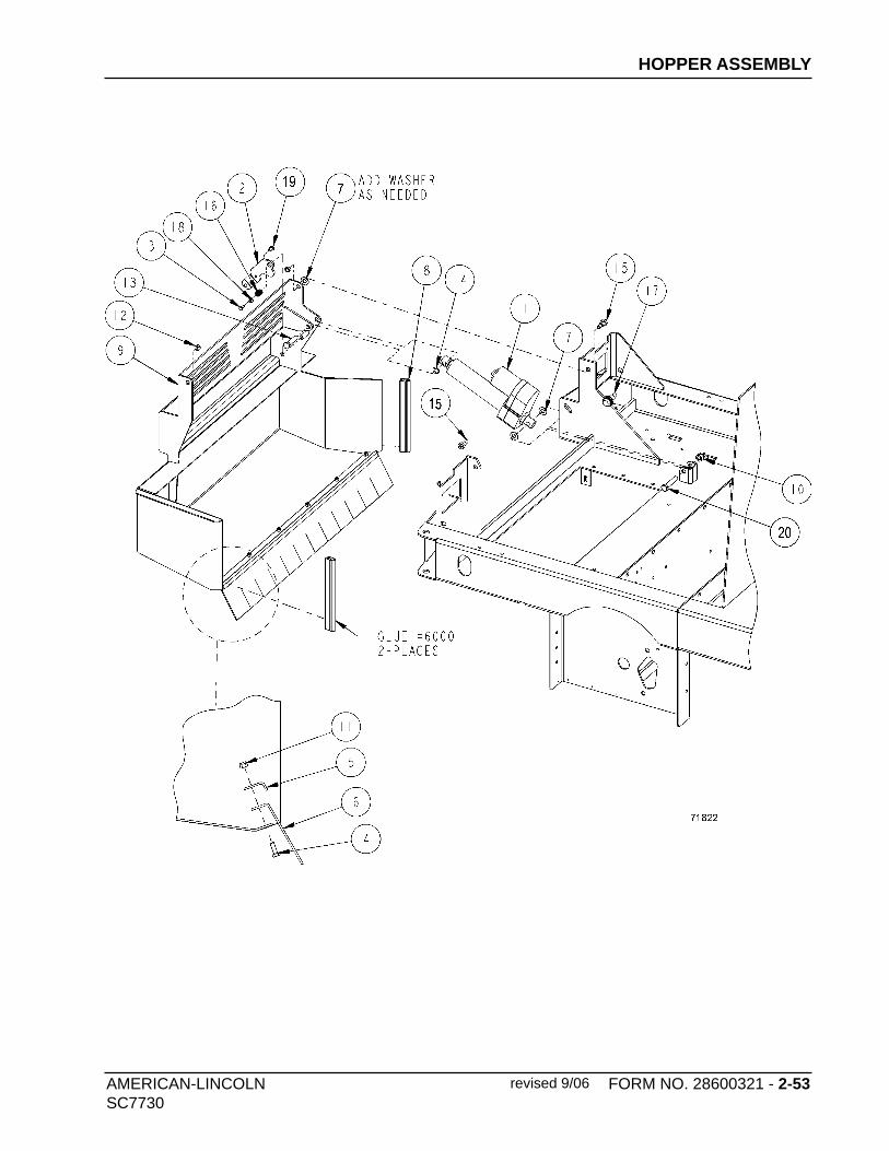
AMERICAN-LINCOLN FORM NO. 28600321 - 2-53SC7730
HOPPER ASSEMBLY
revised 9/06

2-54 - FORM NO. 28600321 AMERICAN-LINCOLN SC7730
DUST CONTROL
KEY NO. QTY PART NUMBER DESCRIPTION
1 1 8-48-00019 MANIFOLD, IMPELLOR (WELDMENT)2 1 8-08-00796 BRACKET, IMPELLOR MOTOR & GUARD3 4 2-00-00213 SCREW, .313-18 x .625 HHC
4 4 2-00-00644 HEX NUT, INSERT FIBER 5/16-185 1 0882-062 MOTOR, IMPELLOR (Motor brush: 0875-142/4 required)
6 4 2-00-00518 LOCK WASHER, 1/4 HEL. SPRNG
7 4 2-00-00221 HEX BOLT, FIN., 1/4-20x3/4 LG8 1 8-23-00013 IMPELLOR9 2 2-00-00263 SET SCREW, HS KNURLED CUP PT. #10-24 x 3/8
10 1 8-55-08114 PIN, SHAKER PIVOT11 4 2-00-03589 COLLAR12 1 7-58-05278 PLATE, SHAKER MOTOR
13 1 7-03-04135 ARM, SHAKER14 2 2-00-03702 WASHER, .625 x .281 x .06315 6 2-00-00641 NUT, 1/4-20 FIBER INSERT
16 6 2-00-03575 CARRIAGE BOLT, 1/4-20 x .7517 1 8-16-07406 COVER, SHAKER MOTOR18 1 0860-624 MOTOR, FILTER SHAKER (36V)
19 1 8-89-04019 WEIGHT, FILTER SHAKER20 1 2-00-00264 SETSCREW, HS KNURLED CUP PT. 1/4-20 x 5/1621 2 8-29-00228 GASKET, DUST CONTROL
22 2 8-29-00229 GASKET, DUST CONTROL23 1 7-81-00219 SUPPORT, PIVOT (IMPELLOR MANIFOLD)24 2 2-00-02708 HEX SCREW, 5/16-18 x 1.0
25 2 2-00-00409 FLAT WASHER, .687 x .344 x .06226 2 2-00-00644 HEX NUT, 5/16-18 FIBER INSERT
c1049/0403

AMERICAN-LINCOLN FORM NO. 28600321 - 2-55SC7730
DUST CONTROL
C1049/0403

2-56 - FORM NO. 28600321 AMERICAN-LINCOLN SC7730
DUST CONTROL (CON’T)
KEY NO. QTY PART NUMBER DESCRIPTION
1 REF 7-27-07224 MAIN FRAME WELDMENT2 1 7-05-01004 BAFFLE, FILTER
3 1 7-08-00960 BRACKET, MANIFOLD PIVOT4 6 2-00-00409 FLAT WASHER, .687 x .344 x .062
5 8 2-00-02708 HEX SCREW, 5/16-18 x 1.06 12 2-00-00644 HEX NUT, INSERT FIBER 5/16-18
7 1 7-57-05061 PIVOT, IMPELLOR MANIFOLD8 4 2-00-00213 SCREW, .313-18 x .625 HHC
9 1 8-24-04074-1 FILTER, PANEL 8-24-04074-2 POLY PANEL FILTER OPTION
10 1 8-80-05038 ROD, THREADED 5/16-1811 1 7-39-00006 KNOB
c1050/0403
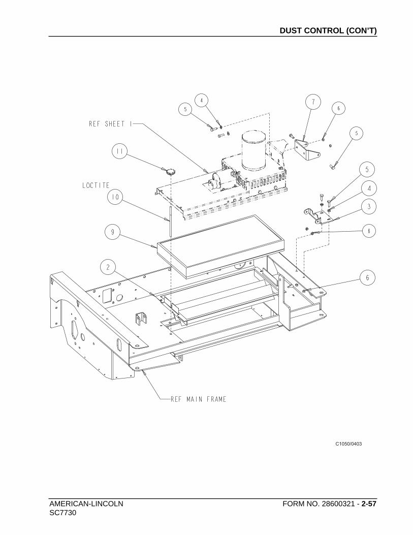
AMERICAN-LINCOLN FORM NO. 28600321 - 2-57SC7730
C1050/0403
DUST CONTROL (CON’T)
2-58 - FORM NO. 28600321 AMERICAN-LINCOLN SC7730
VAC MANIFOLD SYSTEM
KEY NO. QTY PART NUMBER DESCRIPTION
1 1 7-48-00036 VAC MANIFOLD 2 2 7-58-05213 PLATE, VAC MOTOR MOUNT 3 1 8-88-00016 VALVE, DUST UNLOADER
4 1 2-00-03407 CLAMP, HOSE (WITTECK #10P) 5 2 2-00-02216 CLAMP, HOSE 6 1 7-33-02395 HOSE, FLEXIBLE (43” LONG)
7 1 7-06-05007 BLOCK, TERMINAL 8 4 2-22-00003 GASKET 9 8 7-80-05083 STUD, VAC MOTOR
10 2 0782-117 MOTOR, VAC FAN (36V)
11 8 2-00-00423 FLAT WASHER, .50 x .219 x .06312 2 2-00-00221 SCREW, 1/4-20 x .75 HHC
13 2 2-00-00518 LOCK WASHER, HELICAL SPRING14 4 2-00-00056 SCREW, #10-24 x .75 RHM
15 8 2-00-01246 HEX NUT, FIBER INSERT #10-2416 4 2-00-04708 TERMINAL
c1052/0403

AMERICAN-LINCOLN FORM NO. 28600321 - 2-59SC7730
VAC MANIFOLD SYSTEM
C1052/0403
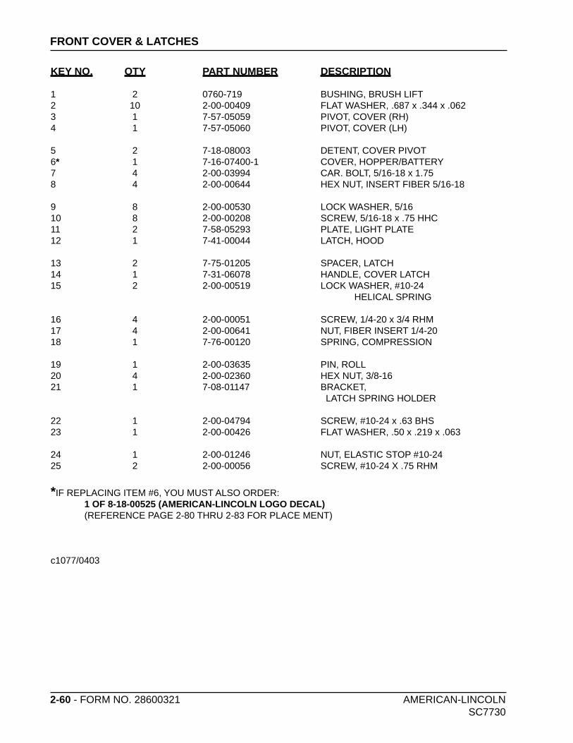
2-60 - FORM NO. 28600321 AMERICAN-LINCOLN SC7730
FRONT COVER & LATCHES
KEY NO. QTY PART NUMBER DESCRIPTION
1 2 0760-719 BUSHING, BRUSH LIFT 2 10 2-00-00409 FLAT WASHER, .687 x .344 x .062 3 1 7-57-05059 PIVOT, COVER (RH) 4 1 7-57-05060 PIVOT, COVER (LH)
5 2 7-18-08003 DETENT, COVER PIVOT 6* 1 7-16-07400-1 COVER, HOPPER/BATTERY 7 4 2-00-03994 CAR. BOLT, 5/16-18 x 1.75 8 4 2-00-00644 HEX NUT, INSERT FIBER 5/16-18
9 8 2-00-00530 LOCK WASHER, 5/16 10 8 2-00-00208 SCREW, 5/16-18 x .75 HHC 11 2 7-58-05293 PLATE, LIGHT PLATE 12 1 7-41-00044 LATCH, HOOD
13 2 7-75-01205 SPACER, LATCH 14 1 7-31-06078 HANDLE, COVER LATCH 15 2 2-00-00519 LOCK WASHER, #10-24 HELICAL SPRING
16 4 2-00-00051 SCREW, 1/4-20 x 3/4 RHM 17 4 2-00-00641 NUT, FIBER INSERT 1/4-20 18 1 7-76-00120 SPRING, COMPRESSION
19 1 2-00-03635 PIN, ROLL 20 4 2-00-02360 HEX NUT, 3/8-16 21 1 7-08-01147 BRACKET, LATCH SPRING HOLDER
22 1 2-00-04794 SCREW, #10-24 x .63 BHS 23 1 2-00-00426 FLAT WASHER, .50 x .219 x .063
24 1 2-00-01246 NUT, ELASTIC STOP #10-24 25 2 2-00-00056 SCREW, #10-24 X .75 RHM
*IF REPLACING ITEM #6, YOU MUST ALSO ORDER: 1 OF 8-18-00525 (AMERICAN-LINCOLN LOGO DECAL) (REFERENCE PAGE 2-80 THRU 2-83 FOR PLACE MENT)
c1077/0403

AMERICAN-LINCOLN FORM NO. 28600321 - 2-61SC7730
*
*
C1077/0403
FRONT COVER & LATCHES

2-62 - FORM NO. 28600321 AMERICAN-LINCOLN
SC7730
SEAT ASSEMBLY
KEY NO. QTY PART NUMBER DESCRIPTION
1 1 2-00-04873 CLAMP, CABLE
2 1 7-58-05297 PLATE, SEAT MOUNTING
3 1 7-72-05005 SEAT ADJUSTER KIT
4# 1 7-69-00008 SEAT
5 1 0875-126 HARNESS, WIRE
6 2 2-00-04578 TERMINAL (.156 MALE)
7# 1 7-82-00050 SWITCH, SEAT
8 1 2-00-00491 GROMMET
9 4 2-00-00644 NUT, INSERT FIBER, 5/16-18
10 5 2-00-00232 SCREW, 3/8-16 x .75 HHC
11 4 2-00-00410 FLAT WASHER, .75 x .390 x .094
12 5 2-00-02310 LOCK WASHER, 3/8 HEL. SPRNG
13 1 2-00-00402 FLAT WASHER, .75 x .391 x .093
# = Revised or new since last update
c1053/0703
revised 9/07

AMERICAN-LINCOLN FORM NO. 28600321 - 2-63
SC7730
SEAT ASSEMBLY
revised 9/07

2-64 - FORM NO. 28600321 AMERICAN-LINCOLN SC7730
HORN ASSEMBLY
C1022/0403
KEY NO. QTY PART NUMBER DESCRIPTION
1 1 8-32-09008 HORN 2 2 2-00-00409 FLAT WASHER, .687 x .344 x .0623 1 2-00-00208 SCREW, 5/16-18 X .75 HHC4 1 2-00-00644 HEX NUT, INSERT FIBER, 5/16-18 5 1 2-00-04873 CLAMP, CABLE
c1022/0403
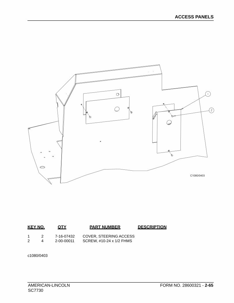
AMERICAN-LINCOLN FORM NO. 28600321 - 2-65SC7730
ACCESS PANELS
C1080/0403
KEY NO. QTY PART NUMBER DESCRIPTION
1 2 7-16-07432 COVER, STEERING ACCESS2 4 2-00-00011 SCREW, #10-24 x 1/2 FHMS
c1080/0403

2-66 - FORM NO. 28600321 AMERICAN-LINCOLN SC7730
INSTRUMENT PANEL
KEY NO. QTY PART NUMBER DESCRIPTION
1 1 7-52-00194 PANEL, INSTRUMENT 2 REF 8-18-00513 DECAL, INSTRUMENT PANEL 3 1 8-82-00041 KEY SWITCH (IGNITION) 4 1 8-82-00030 HORN SWITCH, PUSH BUTTON 5 1 0785-095 HOBBSMETER 6 1 2-00-05904 SOLENOID CONTROLLER, 1 Hz7 7 7-64-00037 RELAY, 36V w/DIODE ASSEMBLY8 1 2-00-05857 LIGHT, HIGH RECOV./LOW SOLUT.9 1 2-00-05858 LIGHT, HOPPER OPEN10 2 2-00-03061 SCREW, #10-24 x 1.0 TRUSS HEAD 11 2 2-00-05262 INSERT, 10-24 THREAD 12 5 8-64-00007 CIRCUIT BREAKER, 10 AMP 13 3 2-00-05869 GASKET, SWITCH 14 3 2-00-05868 SWITCH PLUG, SEALED PANEL
15 2 2-00-05827 SWITCH BODY 16 1 2-00-05828 ROCKER SWITCH BODY, HOPPER17 1 2-00-05829 Rocker Switch Body, Dust Control18 1 2-00-05830 ROCKER SWITCH BODY, SCRUB MODE19 1 2-00-05831 ROCKER SWITCH BODY, SQUEEGEE20 1 8-64-00008 CIRCUIT BREAKER, 15 AMP21 1 2-00-05834 ACTUATOR, FORWARD/REVERSE
22 1 2-00-05850 ACTUATOR, SCRUB MODE23 1 2-00-05849 ACTUATOR, SQUEEGEE24 1 2-00-05852 ACTUATOR, BROOM25 1 2-00-05851 ACTUATOR, DUST CONTROL26 1 2-00-05853 ACTUATOR, HOPPER27 6 8-11-00044 BOOT28 1 7-39-00028 KNOB, SOLUTION FLOW MODULE
29 1 2-00-00071 SCREW, #10-24 x 1.25 LG30 1 8-64-00020 RELAY, TIME DELAY (20 SEC)31 1 2-00-00426 FLAT WASHER, .50 x .219 x .06332 1 2-00-01246 NUT, ELASTIC STOP #10-2433 1 7-52-00196 PANEL, FWD/REV SWITCH34 REF 8-18-00497 DECAL, IGNITION SWITCH35 8 2-00-05923 SCREW, #8-32 x .50 BHSC36 8 2-00-05324 INSERT, #8-32 THREAD
c1034/0803

AMERICAN-LINCOLN FORM NO. 28600321 - 2-67SC7730
C1034/0403
INSTRUMENT PANEL

2-68 - FORM NO. 28600321 AMERICAN-LINCOLN SC7730
POWER PANEL
KEY NO. QTY PART NUMBER DESCRIPTION
1 1 7-52-00193 PANEL, POWER2 1 0795-173 HARNESS, POWER PANEL - BATTERY3 4 8-06-05004 TERMINAL BLOCK4 2 2-00-00203 HEX SCREW, 1/4-20 x 1.50
*5 1 8-28-05019 FUSE (70 AMP) ACK-70 (Cooper-Bussmann PN)*6 1 8-28-05021 FUSE (120 AMP) ACK-120 (Cooper-Bussman PN)
7 8 2-00-03702 WASHER, .625 x .281 x .0638 8 2-00-00594 HEX NUT, 1/4-20
9 4 2-00-00518 LOCK WASHER, 1/4 HEL. SPRNG10 2 2-00-02336 NUT, SPECIAL11 3 2-00-04825 SOLENOID12 14 2-00-00426 FLAT WASHER, .50 x .219 x .063
13 18 2-00-01246 NUT, ELASTIC STOP #10-2414 4 2-00-00409 FLAT WASHER, .687 x .344 x .06215 4 2-00-00644 HEX NUT, INSERT FIBER 5/16-1816 2 2-00-00208 SCREW, 5/16-18 x .75 HHC
17 1 7-16-07460 COVER, POWER PANEL18 1 7-16-07463 COVER, POWER PANEL19 7 2-00-03940 SCREW, T/C HH #10-24 x .50 LG20 1 7-35-00023 INSULATION, PWR. PANL. COVER
21 8 2-00-00039 SCREW, #10-2422 1 7-35-00024 INSULATION, PWR. PANL. COVER23 2 7-15-08009 CONTACTOR, WR-TYPE 586 SPNO24 10 2-00-00049 SCREW, RHM 10-24 x .50 ZN PL
25 2 7-64-00032 CIRCUIT BREAKER, 50 AMP 26 1 7-64-00025 CIRCIUT BREAKER, 25 AMP 27 3 8-11-00051 CAP, CLEAR BOOT
28 1 0785-107 CONTROLLER, TRACTION DRIVE 29 2 2-00-00402 WASHER, 25/64 ID x 3/4 OD
*These fuses manufactured by: Cooper-Bussman, Inc., P.O. Box 14460, St. Louis, MO 63178-4460
c1079/7-05
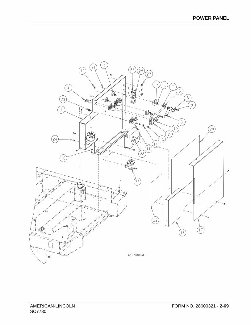
AMERICAN-LINCOLN FORM NO. 28600321 - 2-69SC7730
C1079/0403
POWER PANEL
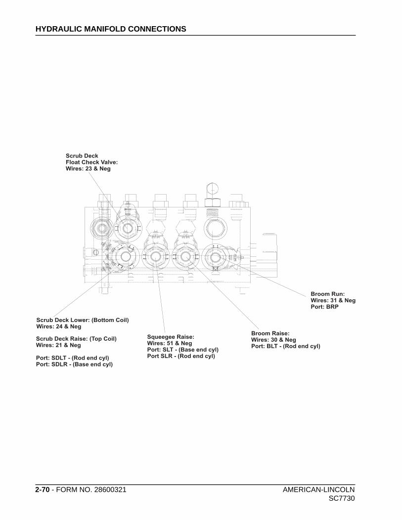
2-70 - FORM NO. 28600321 AMERICAN-LINCOLN SC7730
HYDRAULIC MANIFOLD CONNECTIONS
Scrub DeckFloat Check Valve:Wires: 23 & Neg
Scrub Deck Lower: (Bottom Coil)Wires: 24 & Neg
Broom Raise:Wires: 30 & NegPort: BLT - (Rod end cyl)
Broom Run:Wires: 31 & NegPort: BRP
Squeegee Raise:Wires: 51 & NegPort: SLT - (Base end cyl)Port SLR - (Rod end cyl)
Scrub Deck Raise: (Top Coil)Wires: 21 & Neg
Port: SDLT - (Rod end cyl)Port: SDLR - (Base end cyl)

American-Lincoln 2-70.5
SC7730
HYDRAULIC SCHEMATIC

Am
erica
n-L
inco
ln 2-7
1
SC
77
30
EL
EC
TR
ICA
L S
CH
EM
AT
IC
M1
B+
F2
F1
M2
B-
19
81
6
B1
A
346
36 V BATTERY BANK
KEY SW.
1A
R4
R5
R3
R6
R7
R1
R2
R5
R4
Shaker Run
Hopper open
Scrub speed
Reverse
Neutral
1A
5
7
AA P2 P1NEG
9
6
8
12
12A
13
1410
11
11
NEG
10
10
20
3
20
20
20
36
37
39
40
503
50
50
3 60
61
NEG
63
62
3 80
80
80
MC1
KEY SWITCH
10
10 91
6393
37
36
39
97
97
NEG
NEG
NEG
A1
A2
F1
F2
MC2
83
81
59
70 71
56
54
55
57
58
51
52
53
NEG
26
26 3541
NEG
27 28
29
3232
30
31
33
23
21
23
24
25
2
1
1A
1B
2B
DC
Sol Vac
DC MOTOR
Vac
Hyd Pump
Vac
SHAKER MOTOR
SIDE BROOM
DC CONTACTOR
SOL WATERFlow
SOL WATER valves
EC +Power
Traction controller PIN # 1
Traction controller PIN # 9
Forward Input
Reverse Input
Scrub Speed Input
Jumper wire
Neutral Output
Traction controller PIN # 3
Traction controller PIN # 6
Traction controller PIN # 2
M
M
M
M
M
M
M
M
M
SD DRIVES
SD DRIVES Contactor
FU1570 AMP.CB-1
10 AMP.
CB-750 AMP.
CB-850 AMP.
CB-950 AMP.
CB-210 AMP.
CB-610 AMP.
Hyd pump contactor
Hour Counter (-)
Hour Counter (+)
Key Switch (+)
Low voltage drop out relay (+)
Low voltage drop out relay (-)
Battery (-)
Battery (+)
Battery (+)
11
88
SD UP
SD NORMAL
SD HEAVY SD LOWER
SD FLOAT
SD RAISE
BROOM
BROOM Raise
MAIN BROOM RUN
Hopper OpenA
WET SWEEP
DC AUTO
SHAKER
5
6
2
2
1
3 6
71
TD-1 2
FWD/REV SW
R1
R3
R6
R7
R2
BACK UP ALARM
CB-310 AMP.
CB-510 AMP.
SQ OFF
5
2
2
2
2
1
1
1
3
1
1
1
3
32
5
6
4
4
SQ ON
SQUEEGGEE Raise
SOL VAC
Main Contactor
M Hopper Actuator
2
5
3
4
6
1
CB-410 AMP.
CB-610 AMP.
M
Option Spray PumpSpray Pump Option SW
W
W
W
Head light
Head light
Tail light
HORN
BEACON LIGHT
HORN SWITCH
lightSWITCH
HIGH RECOVERY
ESP Enable
HIGH Solution
HIGH RECOVERYESP Option Pump SW
Low SolutionLow Solution
MESP Option Pump
A
A
Hopper Closed
M FMain Contactor
Traction Drive Field Coil
Traction Drive motor
SeatSWITCH
Throttle
FU13120 AMP.
M+M-
B- B+
10
36
37
93
63
91

American-Lincoln 2-72 SC7730
CONNECTION DIAGRAM
97
Ne
gN
eg
Scru eck Lowerb D
Scrub Deck Float
RBroom un
S RU EC W V LVEC B D K FLO A
Hr
on
BA KU LAC P A RM
CSEAT SWIT H
Va
ors
c M
ot
iScrub Deck Ra se
o RaisBr om e
eegee R eSqu ais
24-18-6-T
23A-18-6-T
31A-18-6-T
SVN
EG
-10-5
-.5
strip
pe
d
SMN
EG
-08
-5
21-18-6-T
30-18-6-T
51-18-6-T
B
AP.E.D.
B
AP.E.D.
B
AP.E.D.
B
AP.E.D.
B
AP.E.D.
B
AP.E.D.
NEG-18-6-T
NEG-18-6-T
NEG-18-6-T
NEG-18-6-T
NEG-18-6-T
NEG-18-6-T
P2-10-4.5-D5/16
55A-18-8-T
59A-18-8-T
13
-18-5
-A
14
-18
-5-A
P1NEG-10-3-D5/16
50C-18-6-C
50D-18-6-WINGED
50E-18-6-WINGED50D-18-6-C
8-1
0-5
-.5
strip
pe
d
12
-08-5
NEG-18-6-A
83-18-6-A
NEG
-18
-8-C
93-1
8-8
-C
40B-18-6-A
NEG-18-6-A
NEG
-18
-3-T
NEG
-18-3
-T
97
-18
-3-T
+ _
CONNECTOR “C”
CONNECTOR “B”
CONNECTOR “A”
An
de
rson
co
nn
ec
tor
CONNECTOR “D”
CONNECTOR “E”
CONNECTOR “F”
10031003
11
2B2B
33
KEY SWITCH FED REV SWITCH
8383
1A1A 3A3A 3B3B
22
NE
GN
EG
36
36 37
37
8080
HORNSWITCHHORN
SWITCH
BATTBATT
ACCACC
IGNIGN
STARTSTART
LEGENDH-
J-
K-
L-
M-
S-
N----
P----
T----
U----
.156 FULLY INSULATED MALE BULLET PLUG
TYPE (1) SLEEVE (FEM) PART N0. 12124580 -14,16AWG.
.TYPE (1) SLEEVE (FEMALE) PART N0. 12124581 -12AWG.
.TYPE (1)PIN (MALE) PART N0. 12124582 14,16 AWG.
.TYPE (1)P1N (MALE) PART N0. 12124587 -12 AWG.
PACKARD (MALE) PART NO. 8917283-10-12 AWG.
PACKARD (FEMALE) PART NO. 2977615-10 AWG.
METRI-PACK 150 (FEMALE TERMINAL-SEALED) .
METRI-PACK 280 (FEMALE TERMINAL-SEALED) .
.25 FULLY INSULATED MALE
A-
B-
C-
D-
E-
F-
G
REPRESENTS WIRE IN HARNESS
REPRESENTS WIRE NOT HARNESSED
.25 FULLY INSULATED FEMALE
.25 INSULATED FEMALE
.156 FULLY INSULATED FEMALE BULLET RECEPTICAL
INSULATED RING TERMINAL
INSULATED SPRING SPADE TERMINAL
INSULATED BUTT CONNECTOR
NON. INSULATED RING TERMINAL
5-12-6-D-.31
WIRE NUMBER
WIRE AWG.
DISTANCE TO HARNESSOR NEXT WING WIRE
STUD SIZE FOR RING ORSPRING SPADE TERMINALS
TERMINAL LEGEND
= DISTANCE TO THE DATUM
DRAWING TOLERANCE (+.75) (-.00).
To Drive Wheel motorA1 D1
A2 D2
A1
-10
-10
-D
5/1
6
F1-1
0-6
.5 -
D 5
/16
F2-1
0-6
.5 -
D 5
/16
A2
-10
-12
-D
5/1
6
D ive Motorr
79 170 5- 4
T a tio to rnr c n mo r ha ess
SOL VAC
CONTACTOR
Pump
CONTACTOR
Battery Neg
Battery Pos
120 mpA
70 p
Am
SCRU
B D
RIV
ES
CO
NTA
CTO
R
Tra
ctio
n D
rive
Co
ntro
l
MA
IN
CO
NTA
CTO
R
CB
7
CB
9
CB
8
7-10-16.5-D1/4
P2-10-15-D5/16
1A
-8-
9 -T
1A-10- 9 -T
Part
of 0
79
5-1
73
Mis
c w
ire
Kit
Part of 0795-173 Misc wire Kit
9-8-11.5-D5/16
MC1-8-7-D5/16
1B-8- 3-T 2B-10- 3-T
28-18-6-A
NEG-18-6-A
6-1
2-6
-A
NEG
DC
-12
-6-S
8-10-5-D5/16
AA-10-4-D5/16
AA
-10
-4-D
10
7-1
0-1
6-D
10
5-1
2-9
.5-D
10
53-18-2-D10
33-18-2-D10
NEG-18-2-D10
10-18-2-D10
NEG-18-2-D10
0775-281DIODE ASSY(INCLUDED WITH 0775-171)
0775-281DIODE ASSY(INCLUDED WITH 0775-171)
Dust ControlMotor
ShakerMotor
0775-281DIODE ASSY(INCLUDED WITH 0775-171)
0775-281DIODE ASSY(INCLUDED WITH 0775-171)
NEG-18-2-D10
50E-18-9-PIN1
54-18-9-PIN4
MC
1-0
8-1
6-D
5/1
6
12
-08
-15
-D5
/16
9-0
8-1
2-D
5/1
6
SDNEG-08-7-D1/4
NEG-12-7-D1/4
SVNEG-10-7-D1/4
P1NEG-10-7-D1/4
NEGDC-12-7-D1/4
TCNEG-08-7-D1/4
12A
-18
-WIN
GED
10
-18-8
-D1
01
1B-1
8-1
4-D
10
NEG
-18
-13
-D1
09
1-1
8-8
-D1
0
62-18-4
61-18-4
NEG -18-6-H
Side Broom
31A -18-6-C
NEG-18-9-PIN3
HOPPER PxM12 FEM STRAIGHT
HOPPER ACTUATOR CONNECTOR IS PACKARD #2973781TERMINALS ARE 2962447
DC
CONTACTOR
5-12-9.5-D1/4
6-12-11.5-D5/16
F1
B+
M1
B-
F2
M21
A
3 4
6
F1-1
0-5
-D.2
5
A1-8
-8-D
5/1
6
MC
2-8
-16-D
5/1
6
MC
2-8
-16-D
5/1
6
TCN
EG
-8-1
9-D
5/1
6
A2-8
-8-D
5/1
6
F2-1
0-9
-D.2
5
NEG-18-6-D5/16
19
816
B
10
36
37
97
9363
91
39
0795-174
0795-171
Part
of 0
79
5-1
73
Mis
c w
ire
Kit
Part
of 0
79
5-1
73
Mis
c w
ire
Kit
TOP -BACK VIEW
R18686868686
86
86
R7
M+M-
B- B+
CB1TDR-1
CB5
CB2
CB6
CB3
CB4
Option Switch locations:Switch Blanks installed standard
11
88
10031003
11
2B2B
33
10031003
11
2B2B
33
10031003
11
2B2B
33
10031003
11
2B2B
33
4411
5B5B2B2B
6633
20052005
4411
5B5B2B2B
6633
20062006
4411
5B5B2B2B
6633
30013001
4411
5B5B2B2B
6633
30023002
A+B-
A+B-
A+B-
20
B2
0C
32
32
54
26
A2
6A
26
B
NEG
1314
12
A
59
B
55
B
32
NEG
NEG
NEG
NEG
11A
25
10
1010
20A
20B
10
10
50A50C50D
80
60
27
28
3A
2
3B
3B
3E
3D
3D
20
F2
1
50
A5
0B
50
B
52
29
30
30
31
A3
1C
31
C3
3
NEG
NEG
NEG
NEG
NEG
NEG
60
59
A5
9B
11
A
11
B 63
NEG
6261
35
26
B
55
A5
5B
53 52 39
20
C2
0D
20
D
20
E
25
37
A3
741
29 27
35
41A 41
NEG
20B
51
40
A
40
A4
0B
23
A2
3
23
B
24
SCRUB MODEVAC MODEDIODE 0775-246
SWEEP MODEDC MODEHOPPER
36 7
1
TD-1
2

5730 Machine harness0795-171
TOP -BACK VIEW
R18686868686
86
86
R7
M+M-
B- B+
CB1TDR-1
CB5
CB2
CB6
CB3
CB4
Option Switch locations:Switch Blanks installed standard
11
88
10031003
11
2B2B
33
10031003
11
2B2B
33
10031003
11
2B2B
33
10031003
11
2B2B
33
4411
5B5B2B2B
6633
20052005
4411
5B5B2B2B
6633
20062006
4411
5B5B2B2B
6633
30013001
4411
5B5B2B2B
6633
30023002
A+B-
A+B-
A+B-
20
B
20
C
32
32
54
26
A2
6A
26
B
NEG
1314
12
A
59
B
55
B
32
NEG
NEG
NEG
NEG
11A
25
10
10
10
20A
20B
10
10
50A50C
50D
80
60
27
28
3A
2
3B
3B
3E
3D
3D
20
F
21
50
A5
0B
50
B
52
29
30
30
31
A
31
C
31
C
33
NEG
NEG
NEG
NEG
NEG
NEG
60
59
A5
9B
11
A
11
B 63
NEG
62
61
35
26
B
55
A5
5B
53
52 39
20
C
20
D
20
D
20
E
25
37
A3
741
29
27
35
41A 41
NEG
20B
51
40
A
40
A
40
B2
3A
23
23
B
24
SCRUB MODEVAC MODE
DIODE 0775-246
SWEEP MODEDC MODEHOPPER
36 7
1
TD-1
2
American-Lincoln 2-73 SC7730
CONNECTION DIAGRAM
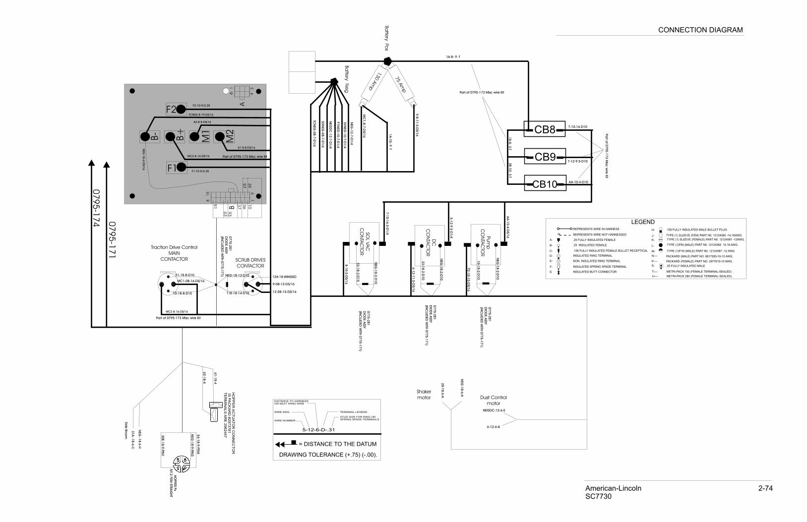
American-Lincoln 2-74 SC7730
CONNECTION DIAGRAM
SOL V
AC
CO
NTA
CTO
R
Pum
p
CO
NTA
CTO
R
Dust Control
motor
Shaker
motor
Ba
ttery N
eg
Ba
ttery Po
s
130 A
mp
p
75
Am
SCRUB DRIVES
CONTACTOR
Traction Drive Control
MAIN
CONTACTOR
CB8
CB10
CB9
-D1/4
7-1
0-1
6.5
P2
-10-1
5-D
5/1
6
1A-8- 9 -T
1A
-10- 9
-T
Part of 0795-173 Misc wire Kit
Pa
rt of 0
795-1
73 M
isc w
ire K
it
9-8
-11.5
-D5/1
6
MC
1-8
-7-D
5/1
6 1B-8
- 3-T
2B-1
0- 3
-T
-A28-1
8-6
NEG
-18-6
-A
6-12-6-A
NEGDC-12-6-S
8-1
0-5
-D5/1
6
AA
-10-4
-D5/1
6
AA-10-4-D10
7-10-16-D10
7-12-9.5-D10
53-1
8-2
-D10
33-1
8-2
-D10
NEG
-18-2
-D10
10-1
8-2
-D10
NEG
-18-2
-D10
0775-2
81
DIO
DE A
SSY
(INC
LUD
ED
WITH
07
75-1
71)
0775-2
81
DIO
DE A
SSY
(INC
LUD
ED
WITH
0775-1
71)
0775-2
81
DIO
DE A
SSY
(INC
LUD
ED
WITH
0775-1
71)
0775-2
81
DIO
DE A
SSY
INC
L(
UD
ED
WITH
07
75-1
71)
NEG
-18-2
-D10
50E-1
8-9
-PIN
1
54-1
8-9
-PIN
4
MC1-08-16-D5/16
12-08-15-D5/16
9-08-12-D5/16
SD
NEG
-08-7
-D1/4
EG
-12-7
-D1/4
NSVN
EG
-10-7
-D1/4
P1N
EG
-10-7
-D1/4
NEG
DC
-12-7
-D1/4
TCN
EG
-08-7
-D1/4
12A-18-WINGED
10-18-8-D10 011B-18-14-D1
NEG-18-13-D1091-18-8-D10
62-1
8-4
61-1
8-4
NEG
-18-6
-H
Sid
e B
roo
m -18-6
-C31A NEG
-18-9
-PIN
3
HO
PPER P
x
M12 F
EM
STR
AIG
HT
HO
PP
ER
AC
TU
AT
OR
CO
NN
EC
TO
R IS
PA
CK
AR
D #
29
73
78
1T
ER
MIN
AL
S A
RE
29
62
44
7
DC
CO
NTA
CTO
R
5-1
2-9
.5-D
1/4
6-1
2-1
1.5
-D5/1
6
F1
B+
M1
B-
F2
M2
1
A
346
F1-10-5-D.25
A1-8-8-D5/16
MC2-8-16-D5/16
MC2-8-16-D5/16
TCNEG-8-19-D5/16
A2-8-8-D5/16
F2-10-9-D.25
NEG
-18-6
-D5/1
6
19
81
6
B
10
36
37
97
93
63
91
390
79
5-1
74 07
95
-17
1
Part of 0795-173 Misc wire Kit
Part of 0795-173 Misc wire Kit
LEGENDH-
J-
K-
L-
M-
S-
N----
P----
T----
U----
.156 FULLY INSULATED MALE BULLET PLUG
TYPE (1) SLEEVE (FEM) PART N0. 12124580 -14,16AWG.
.TYPE (1) SLEEVE (FEMALE) PART N0. 12124581 -12AWG.
.TYPE (1)PIN (MALE) PART N0. 12124582 14,16 AWG.
.TYPE (1)P1N (MALE) PART N0. 12124587 -12 AWG.
PACKARD (MALE) PART NO. 8917283-10-12 AWG.
PACKARD (FEMALE) PART NO. 2977615-10 AWG.
METRI-PACK 150 (FEMALE TERMINAL-SEALED) .
METRI-PACK 280 (FEMALE TERMINAL-SEALED) .
.25 FULLY INSULATED MALE
A-
B-
C-
D-
E-
F-
G
REPRESENTS WIRE IN HARNESS
REPRESENTS WIRE NOT HARNESSED
.25 FULLY INSULATED FEMALE
.25 INSULATED FEMALE
.156 FULLY INSULATED FEMALE BULLET RECEPTICAL
INSULATED RING TERMINAL
INSULATED SPRING SPADE TERMINAL
INSULATED BUTT CONNECTOR
NON. INSULATED RING TERMINAL
5-12-6-D-.31
WIRE NUMBER
WIRE AWG.
DISTANCE TO HARNESSOR NEXT WING WIRE
STUD SIZE FOR RING ORSPRING SPADE TERMINALS
TERMINAL LEGEND
= DISTANCE TO THE DATUM
DRAWING TOLERANCE (+.75) (-.00).
97
Ne
gN
eg
Scrub Deck Lower
cr ck loaS ub De F t
Broom Run
B D L ASCRU ECK F OW V LVE
Ho
rn
BACKUP ALARM
SEAT SWITCH
Va
Mo
tor
cs
Scrub Deck Raise
Broom Raise
Squeegee Raise
24-18-6-T
23A-18-6-T
31A-18-6-T
SVN
EG
-10
-5-.
5 s
trip
pe
d
SMN
EG
-08
-5
21-18-6-T
30-18-6-T
51-18-6-T
B
AP.E.D.
B
AP.E.D.
B
AP.E.D.
B
AP.E.D.
B
AP.E.D.
B
AP.E.D.
NEG-18-6-T
NEG-18-6-T
NEG-18-6-T
NEG-18-6-T
NEG-18-6-T
NEG-18-6-T
P2-10-4.5-D5/16
55A-18-8-T
59A-18-8-T
13
-18
-5-A
14-1
8-5
-A
P1NEG-10-3-D5/16
50C-18-6-C
50D-18-6-WINGED
50E-18-6-WINGED50D-18-6-C
8-1
0-5
-.5 s
trip
pe
d
12-0
8-5
NEG-18-6-A
83-18-6-A
NEG
-18-8
-C
93-1
8-8
-C
40B-18-6-A
NEG-18-6-A
NEG
-18-3
-TN
EG
-18-3
-T
97-1
8-3
-T
+ _CONNECTOR “C”
CONNECTOR “B”
CONNECTOR “A”
An
de
rson
co
nn
ec
tor
CONNECTOR “D”
CONNECTOR “E”
CONNECTOR “F”
10031003
11
2B2B
33
KEY SWITCH FED REV SWITCH
To Instrument panel
8383
1A1A 3A3A 3B3B
22
NE
GN
EG
36
36 37
37
8080
HORNSWITCHHORN
SWITCH
BATTBATT
ACCACC
IGNIGN
STARTSTART
0795-174
0795-171
To Power PanelA1 D1
A2 D2
A1
-10-1
0 -
D 5
/16
F1-1
0-6
.5 -
D 5
/16
F2-1
0-6
.5 -
D 5
/16
A2-1
0-1
2 -
D 5
/16
D ive M torr o
0795-174
Traction motor harness
American-Lincoln 2-75 SC7730
CONNECTION DIAGRAM

American-Lincoln 2-76
SC7730
HARNESS ROUTING DIAGRAM
0795-174: Traction Motor Harness
0795-174: Traction Motor Harness
0795-174: Traction Motor Harness
0795-173: PowerPanel misc. Wire set

0795-18146” scrub deck harness
0795-18040” scrub deck harness
(+) TOPTERM.
(+) TOPTERM.
(+) TOPTERM.
(+) TOPTERM.
(+) TOPTERM.
Neg
Neg
Neg
Neg
Neg
Neg
12
Neg
Neg
Neg
12
12
12
12
12
12
Neg
12
12
12
A B
+ -
12
American-Lincoln 2-77 SC7730
SCRUB DECK CONNECTION DIAGRAM

AMERICAN-LINCOLN FORM NO. 28600321 - 2-77SC7730
THIS PAGE HAS BEEN LEFT BLANK INTENTIONALLY -
do not remove
INSERT SCRUB DECK CONNECTION DIAGRAM(PAGE 77)

2-78 - FORM NO. 28600321 AMERICAN-LINCOLN SC7730
BATTERY ROLLOUT
revised 9/06
KEY NO. QTY PART NUMBER DESCRIPTION
1 31 2-00-00405 FLAT WASHER, 1.063 x .531 x .094 2 17 2-00-03306 BALL BEARING 3 11 2-00-01254 HEX SCREW, 1/2-13 x 1.50
4 3 2-00-01778 SCREW, 1/2-13 x 2.0 HHC 5 14 2-00-04936 LOCKNUT, ELASTIC 1/2-13 6 1 7-57-05063 PIVOT, BATTERY BAR
7 1 7-05-07179 BAR, BATTERY 8 4 2-00-00233 HEX BOLT, FIN., 3/8-16 x 1.09 4 2-95-04182 NUT, HEX STOP 3/8-16
10 2 2-00-00644 HEX NUT, INSERT FIBER 5/16-18 11 2 2-00-02708 HEX SCREW, 5/16-18 x 1.0
12 1 7-78-05029 STOP, BATTERY (720 AH) 13 1 7-51-05017 PAN, BATTERY 14 1 7-75-01199 SPACER, BATTERY STOP (510 AH)
71830

AMERICAN-LINCOLN FORM NO. 28600321 - 2-79SC7730
BATTERY ROLLOUT
revised 9/06

2-80 - FORM NO. 28600321 AMERICAN-LINCOLN
SC7730
DECALS
KEY NO. QTY PART NUMBER DESCRIPTION
1 1 8-18-00513 INSTRUMENT PANEL
2 1 8-18-00497 KEY SWITCH
3< 1 REF ATF/DEXTRON HYD. FLUID ONLY
4< 2 REF BATTERY CHARGING WARNING
5< 1 REF COVER/HOPPER COULD CLOSE
6< 1 REF DO NOT USE W/FLAMMABLES
7< 1 REF ELECTRICAL HAZARD
8 1 8-18-00492 HORN
9< 1 REF NO GAS OR COMBUSTIBLES
10<# 2 8-18-00479 NO STEP
11 1 8-18-00496 OPEN FOR DRAIN HOSE
12< 1 REF PATENT/PATENTS PENDING
13< 1 REF TURN OFF - LOCK WHEEL
14< 7 REF PINCH POINT - STAY CLEAR
15 1 8-18-00537 7730
17 1 8-18-00525 AMERICAN-LINCOLN (MEDIUM)
18 2 8-18-00524 AMERICAN-LINCOLN (SMALL)
19 1 REF SERIAL PLATE
20 3 8-50-05022 NON-SKID - FORWARD/REVERSE
21 2 2-00-04115 RIVETS
22# 2 56016163 Decal, No Step
< WARNING DECALS KIT FOR YOUR 7730: ORDER 0760-884
# = Revised or new since last update
C1035B/8-04
revised 9/07

AMERICAN-LINCOLN FORM NO. 28600321 - 2-81
SC7730
DECALS
revised 9/07

2-82 - FORM NO. 28600321 AMERICAN-LINCOLN
SC7730
DECALS CON’T.
KEY NO. QTY PART NUMBER DESCRIPTION
1 1 8-18-00513 INSTRUMENT PANEL
2 1 8-18-00497 KEY SWITCH
3< 1 REF ATF/DEXTRON HYD. FLUID ONLY
4< 2 REF BATTERY CHARGING WARNING
5< 1 REF COVER/HOPPER COULD CLOSE
6< 1 REF DO NOT USE W/FLAMMABLES
7< 1 REF ELECTRICAL HAZARD
8 1 8-18-00492 HORN
9< 1 REF NO GAS OR COMBUSTIBLES
10<# 2 8-18-00479 NO STEP
11 1 8-18-00496 OPEN FOR DRAIN HOSE
12< 1 REF PATENT/PATENTS PENDING
13< 1 REF TURN OFF - LOCK WHEEL
14< 7 REF PINCH POINT - STAY CLEAR
15 1 8-18-00537 7730
17 1 8-18-00525 AMERICAN-LINCOLN (MEDIUM)
18 2 8-18-00524 AMERICAN-LINCOLN (SMALL)
19 1 REF SERIAL PLATE
20 3 8-50-05022 NON-SKID - FORWARD/REVERSE
21 2 2-00-04115 RIVETS
22# 2 56016163 Decal, No Step
< WARNING DECALS KIT FOR YOUR 7730: ORDER 0760-884
# = Revised or new since last update
C1036B/8-04
revised 9/07

AMERICAN-LINCOLN FORM NO. 28600321 - 2-83SC7730
5
5
9
12
14
14
15
18
19
15
18
21
C1036B/0703
DECALS CON’T.

2-84 - FORM NO. 28600321 AMERICAN-LINCOLN SC7730
HYDRAULICS SYSTEM
KEY NO. QTY PART NUMBER DESCRIPTION
1 1 7-83-04183 RESERVOIR 2 1 2-00-02474 PLUG 1/2 NPT 3 1 7-11-00033 FILTER BREATHER 4 3 2-00-02848 SCREW, #10-32 x .50 RHM
5 1 8-48-05033 SIGHT GLASS (HYD. FLUID) 6 1 8-24-04115 STRAINER, HYD. RESERVOIR 7 4 8-50-05037 PAD, RADIATOR MOUNT 8 1 7-60-05044 PUMP, HYDRAULIC
9 1 7-88-00100 MANIFOLD 10 1 2-95-02517 FITTNG, 1/2NPT, NIPPLE, 3.5” , GALV.11 1 2-95-02541 REDUCE BUSHING, 3/4 NPT x 1/2 NPT 12 1 7-24-04013 FILTER ASSEMBLY, RETURN
13 8 2-00-04918 FITTING, -6 SAE x -4 ORS, STR. 14 2 2-00-05340 Fitting, HYD., 9/16-18 ORF x 9/16-18 ST, 45 Elbow15 1 2-00-05914 FITTING, 12-8 ORFS-ORB 16 2 2-00-05435 FITTING, 90 ORFS TO ORS BOSS 06 x 06
17 1 2-00-05442 Fitting, ORFS M TO ORS M BOSS 06 X 0618 1 2-00-05387 FITTING, STR #12 ORS x 3/4-14 NPT 19 1 2-00-05217 FITTING, 90 ELBOW ORFS M TO NPTF M 08 x 1220 4 2-00-00530 LOCK WASHER 5/16”
21 4 2-00-00409 FLAT WASHER, .687 x .344 x .06222 4 2-00-00585 NUT, 5/16-18 HEX 23 6 2-00-00644 NUT, 5/16-18 FIBER INSERT HEX 24 2 2-00-05924 CARRIAGE BOLT, .31-18 X 5.0
25 2 2-00-00402 WASHER, 25/64” ID x 3/4” OD26 4 2-00-03702 FLAT WASHER, .625 x .281 x .06327 4 2-00-00518 LOCK WASHER, 1/4” HEL. SPRING28 4 2-00-02587 SCREW, 1/4-20 x 1.25
71811revF/7-05

AMERICAN-LINCOLN FORM NO. 28600321 - 2-85SC7730
71811revF
HYDRAULICS SYSTEM

2-86 - FORM NO. 28600321 AMERICAN-LINCOLN
SC7730
HYDRAULIC CONNECTION DIAGRAM
KEY NO. QTY PART NUMBER DESCRIPTION
1 1 7-33-02355 HOSE, #4 STR 45,9/16-18 BOTH ENDS, 50.5 LG
2 1 7-33-02573 HOSE, HYD #4 45-STR, 9/16-18 BOTH ENDS, 51 LG
3 1 7-33-02574 HOSE, HYD #4 45-STR, 9/16-18 BOTH ENDS, 45.5 LG
4 1 7-33-02575 HOSE, HYD #4 45-STR, 9/16-18 BOTH ENDS, 47.5 LG
5 1 8-33-02188 HOSE-#4 STR-STR, 9/16-18 BOTH ENDS, 24 LG
6 1 7-33-02577 HOSE, HYD #4 STR-STR, 9/16-18 BOTH ENDS,
21.75 LG
7 1 7-33-02578 HOSE, HYD #4 LONG 90-STR, 9/16-18 BOTH ENDS,
81 LG
8 1 7-33-02579 HOSE, HYD #4 LONG 90-STR, 9/16-18 BOTH ENDS,
74 LG
9 1 7-33-02580 HOSE, HYD #4 STR-STR, 9/16-18 BOTH ENDS, 21 LG
10 1 7-33-02581 HOSE, HYD #4 STR-STR, 9/16-18 BOTH ENDS,
15.75 LG
11# 1 56109086 HOSE-#4 STR-STR, 9/16-18 BOTH ENDS, 37 LG
12# 1 56109087 HOSE-#4 STR-90, 9/16-18 BOTH ENDS, 38 LG
13 1 7-33-02446 HOSE, -12 ORS, STR x 90, 22.5” LONG
14 1 7-33-02585 HOSE, HYD #6, STR-90, 11/16-16 BOTH ENDS, 13 LG
15 1 8-33-02193 HOSE, ORS -8, STR. x STR., 18-1/4” LONG
# = Revised or new since last update
c1024/0403
revised 9/07

AMERICAN-LINCOLN FORM NO. 28600321 - 2-87SC7730
C1024/0403
HYDRAULIC CONNECTION DIAGRAM

2-88 - FORM NO. 28600321 AMERICAN-LINCOLN SC7730
C1025/0403
HYDRAULICS/STEERING CYLINDER & PUMP
KEY NO. QTY PART NUMBER DESCRIPTION
1 REF 7-60-05045 PUMP, STEERING2 REF 7-17-05010-1 CYLINDER, POWER STEERING 3 2 2-00-04895 FITTING, STRAIGHT CONNECTOR
c1025/0403

AMERICAN-LINCOLN FORM NO. 28600321 - 2-89SC7730
C1026/0403
HYDRAULICS/LOW DUMP CYLINDER
KEY NO. QTY PART NUMBER DESCRIPTION
1 REF 7-17-05022 CYLINDER, BROOM 2 2 2-00-04892 FITTING, 90° ELBOW (O-RING)
c1026/0403

2-90 - FORM NO. 28600321 AMERICAN-LINCOLN SC7730
C1027/0403
HYDRAULICS/REAR SQUEEGEE LIFT CYLINDER
KEY NO. QTY PART NUMBER DESCRIPTION
1 REF 7-17-05026 CYLINDER, SQUEEGEE2 2 2-00-04895 FITTING, STRAIGHT CONNECTOR
c1027/0403
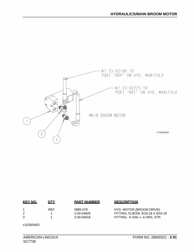
AMERICAN-LINCOLN FORM NO. 28600321 - 2-91SC7730
C1028/0403
HYDRAULICS/MAIN BROOM MOTOR
KEY NO. QTY PART NUMBER DESCRIPTION
1 REF 0885-078 HYD. MOTOR (BROOM DRIVE)2 1 2-00-04926 FITTING, ELBOW, 9/16-18 X 9/16-183 1 2-00-04918 FITTING, -6 SAE x -4 ORS, STR.
c1028/0403

2-92 - FORM NO. 28600321 AMERICAN-LINCOLN SC7730
C1029/0403
HYDRAULICS/40” SCRUB DECK LIFT CYLINDER
KEY NO. QTY PART NUMBER DESCRIPTION
1 REF 7-17-05025 CYLINDER, HYD., SCRUB DECK LIFT2 REF 7-27-07202 FRAME, BRUSH DRIVE (40 IN.)3 2 2 2-00-04892 FITTING, 90° ELBOW (O-RING)
c1029/0403

AMERICAN-LINCOLN FORM NO. 28600321 - 2-93SC7730
C1030/0403
HYDRAULICS/46” SCRUB DECK LIFT CYLINDER
KEY NO. QTY PART NUMBER DESCRIPTION
1 REF 7-17-05020 CYLINDER, HOPPER DOOR2 2 2-00-04892 FITTING, 90° ELBOW (O-RING)3 REF 7-27-07207 FRAME, BRUSH
c1030/0403

2-94 - FORM NO. 28600321 AMERICAN-LINCOLN SC7730
NOTES

AMERICAN-LINCOLN FORM NO. 28600321 - 3-1
SC7730
INDEX - OPTIONS
BBACK-UP ALARM 2
BATTERY STAND 3
EESP RECOVERY 12
ESP RECOVERY/DIMENSIONS 14
ESP RECOVERY/WIRING 15
F
FIRE EXTINGUISHER 4
L
LIGHT PACKAGE 10
O
OVERHEAD GUARD 5
SSEAT BELT 6
SPRAY & VAC WAND 16
SPARAY & VAC WAND/WIRING 19
SQUEEGEE WAND 7
WWARNING LIGHT W/O OVERHEAD GUARD 8
WARNING LIGHT W/ OVERHEAD GUARD 9

3-2 - FORM NO. 28600321 AMERICAN-LINCOLN
SC7730
BACK - UP ALARM OPTION
C1041/0403
OPTION 0780-584
KEY NO. QTY PART NUMBER DESCRIPTION
1 1 8-32-09009 BACK-UP ALARM (9.8 - 56.4 VDC)
2 2 2-00-00221 HEX BOLT, FIN., 1/4-20 x 3/4 LG
3 2 2-00-00409 FLAT WASHER, .687 x .344 x .062
4 2 2-00-00501 WASHER .25 ID x .44 OD x .046
5 2 2-00-00641 NUT, FIBER INSERT 1/4-20
c1041/0403

AMERICAN-LINCOLN FORM NO. 28600321 - 3-3
SC7730
C1062/0403
BATTERY STAND OPTION
OPTION 0780-492
KEY NO. QTY PART NUMBER DESCRIPTION
1 14 2-00-03306 BALL BEARING
2 2 2-00-00216 HEX BOLT, 3/8-16 x 2”
3 17 2-00-00405 WASHER, 1.063 x .531 x .094
4 14 2-00-04936 LOCK NUT, ELASTIC, 1/2-13
5 4 2-00-00643 LOCK NUT, ELASTIC, 3/8-16
6 6 2-00-01254 HEX SCREW, 1/2-13 x 1.50
7 3 7-75-01201 SPACER, BATT. STAND
8 3 7-80-05088 STUD, BATT. STAND
9 1 7-81-00228 SUPPORT, BATT. STAND/LEFT
10 1 7-81-00227 SUPPORT, BATT. STAND/RIGHT
11 2 2-14-00184 WHEEL
12 2 2-00-01778 SCREW, 1/2-13 x 2.000 HHC
13 2 2-00-02694 SCREW, .50-20 x 2.25 HHC
14 2 2-00-00591 HEX JAM NUT, .50-20
c1062/0403

3-4 - FORM NO. 28600321 AMERICAN-LINCOLN
SC7730
USE THE BRACKET
AS A TEMPLATE FOR
REMAINING HARDWARE
C1068/0403
FIRE EXTINGUISHER OPTION
OPTION 0780-482
KEY NO. QTY PART NUMBER DESCRIPTION
1 REF. 7-83-04179-1 SOLUTION TANK
2 1 8-83-04033 FIRE EXTINGUISHER (2.5 LB.)
3 4 2-00-03466 SCREW, #10-16 x .500
c1068/0403
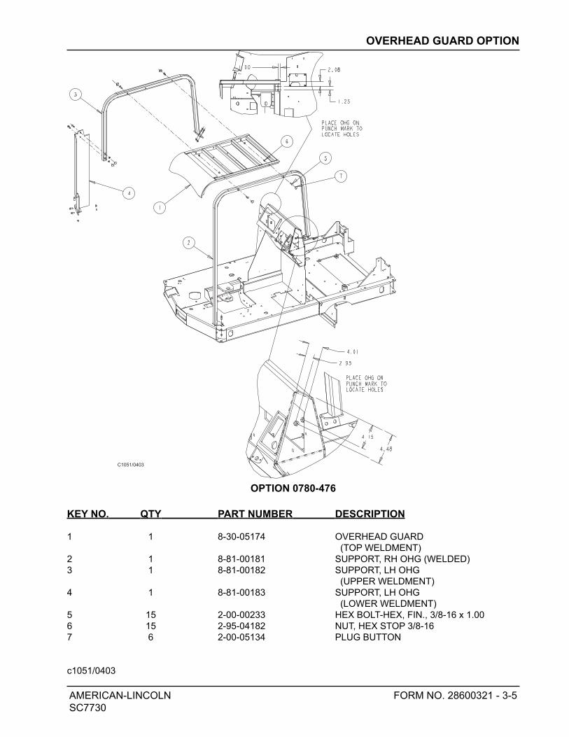
AMERICAN-LINCOLN FORM NO. 28600321 - 3-5
SC7730
C1051/0403
OVERHEAD GUARD OPTION
OPTION 0780-476
KEY NO. QTY PART NUMBER DESCRIPTION
1 1 8-30-05174 OVERHEAD GUARD
(TOP WELDMENT)
2 1 8-81-00181 SUPPORT, RH OHG (WELDED)
3 1 8-81-00182 SUPPORT, LH OHG
(UPPER WELDMENT)
4 1 8-81-00183 SUPPORT, LH OHG
(LOWER WELDMENT)
5 15 2-00-00233 HEX BOLT-HEX, FIN., 3/8-16 x 1.00
6 15 2-95-04182 NUT, HEX STOP 3/8-16
7 6 2-00-05134 PLUG BUTTON
c1051/0403

3-6 - FORM NO. 28600321 AMERICAN-LINCOLN
SC7730
SEAT BELT OPTION
OPTION 0780-493
KEY NO. QTY PART NUMBER DESCRIPTION
1 REF 2-00-00402 WASHER, 25/64 ID x 3/4 OD
2 REF 2-00-02310 LOCK WASHER, 3/8 HEL. SPRNG
3 REF 2-00-00232 HEX BOLT, FIN., 3/8-16
4 1 7-08-00973 BRACKET, SEAT BELT
5# 1 56109301 SEAT BELT, RETRACTABLE 60”
6 2 2-00-00233 HEX BOLT, FIN., 3/8-16 x 1.0
7 2 2-00-00643 LOCKNUT, ELASTIC 3/8-16
# = Revised or new since last update
c1063/0403
revised 9/07
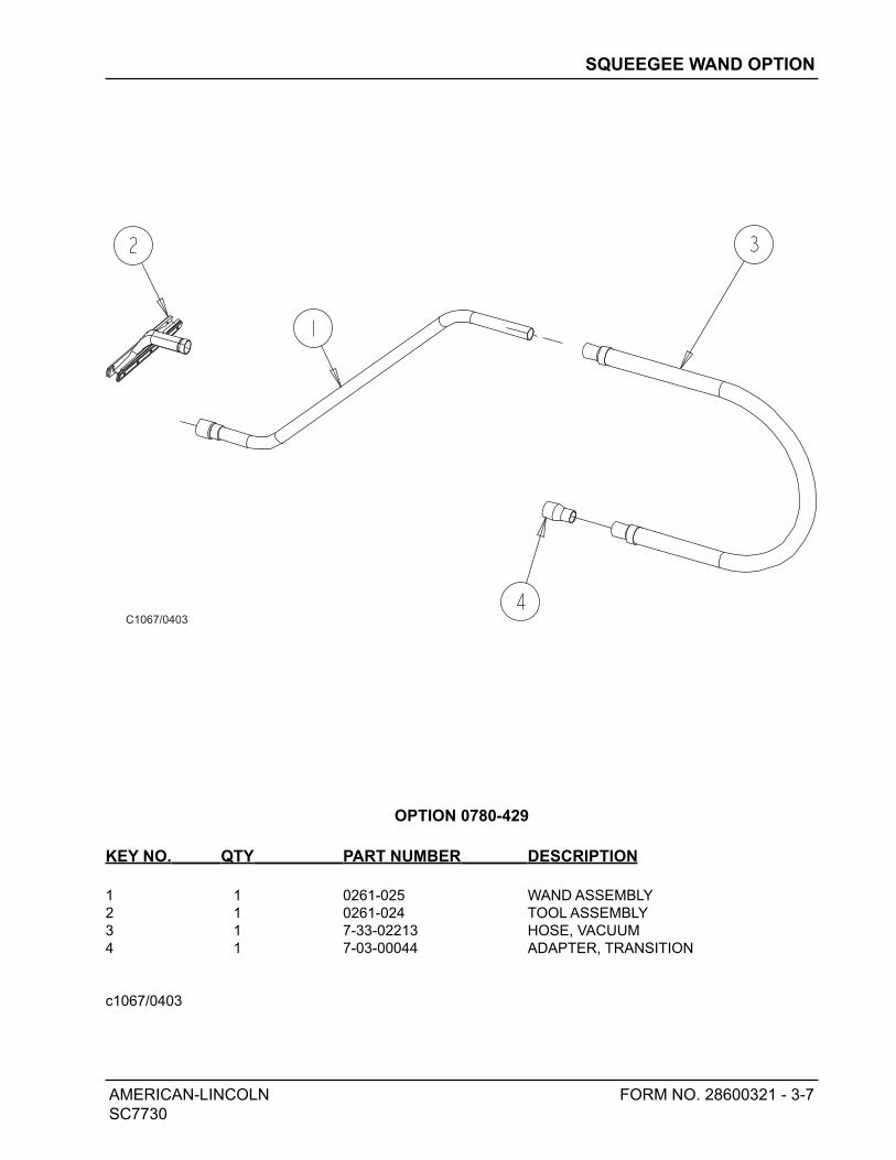
AMERICAN-LINCOLN FORM NO. 28600321 - 3-7
SC7730
C1067/0403
SQUEEGEE WAND OPTION
OPTION 0780-429
KEY NO. QTY PART NUMBER DESCRIPTION
1 1 0261-025 WAND ASSEMBLY
2 1 0261-024 TOOL ASSEMBLY
3 1 7-33-02213 HOSE, VACUUM
4 1 7-03-00044 ADAPTER, TRANSITION
c1067/0403

3-8 - FORM NO. 28600321 AMERICAN-LINCOLN
SC7730
C1069/0403
WARNING LIGHT WITHOUT OHG OPTION
OPTION 0780-589
KEY NO. QTY PART NUMBER DESCRIPTION
1 1 7-81-00223 SUPPORT, WARNING LIGHT
2 1 3-61-02014 CONVOLUTED TUBE (6 FT)
3 1 2-00-03261 GROMMET
4 1 2-00-00491 GROMMET
5 1 8-40-05036 STROBE, AMBER (12 TO 80 VDC)
6 2 2-00-03063 SCREW, ROUND HD., 10-24 x .75
7 2 2-00-00512 WASHER, STAR
8 2 2-00-00605 HEX NUT, #10-24
9 8 2-00-00402 WASHER, 25/64 ID x 3/4 OD
10 4 2-00-00233 HEX BOLT, FIN., 3/8-16 x 1.0
11 4 2-00-02310 LOCK WASHER, 3/8 HEL. SPRNG
12 4 2-00-02360 HEX NUT, 3/8-16
**WIRING DIAGRAM ON PAGE 9
c1069/0403
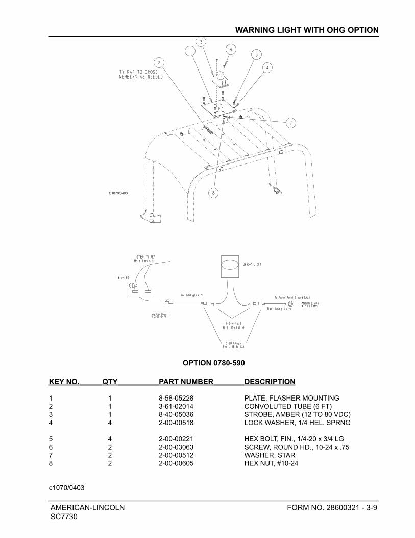
AMERICAN-LINCOLN FORM NO. 28600321 - 3-9
SC7730
C1070/0403
WARNING LIGHT WITH OHG OPTION
OPTION 0780-590
KEY NO. QTY PART NUMBER DESCRIPTION
1 1 8-58-05228 PLATE, FLASHER MOUNTING
2 1 3-61-02014 CONVOLUTED TUBE (6 FT)
3 1 8-40-05036 STROBE, AMBER (12 TO 80 VDC)
4 4 2-00-00518 LOCK WASHER, 1/4 HEL. SPRNG
5 4 2-00-00221 HEX BOLT, FIN., 1/4-20 x 3/4 LG
6 2 2-00-03063 SCREW, ROUND HD., 10-24 x .75
7 2 2-00-00512 WASHER, STAR
8 2 2-00-00605 HEX NUT, #10-24
c1070/0403

3-10 - FORM NO. 28600321 AMERICAN-LINCOLN
SC7730
LIGHT PACKAGE OPTION
OPTION 0780-591
KEY NO. QTY PART NUMBER DESCRIPTION
1 1 8-40-05053 TAIL LIGHT (36V)
2 2 8-75-01207 SPACER, TAIL LIGHT MNTNG
3 2 2-00-02933 SCREW
4 1 2-00-04210 CLAMP
5 2 2-00-01246 NUT, ELASTIC STOP #10-24
6 2 7-08-00557 BRACKET, LIGHT
7 2 7-40-05031 HEAD LIGHT (36V)
8 2 7-29-00191 GASKET, LIGHT
9 4 2-00-00060 SCREW, RHM .25-20 x 1.25
10 4 2-00-00641 NUT, FIBER INSERT 1/4-20
11 1 2-00-05869 GASKET, SWITCH
12 1 2-00-05827 SWITCH BODY
13 1 2-00-05837 ACTUATOR, LIGHT PKG.
c1042/0403

AMERICAN-LINCOLN FORM NO. 28600321 - 3-11
SC7730
C1042/0403
LIGHT PACKAGE OPTION

3-12 - FORM NO. 28600321 AMERICAN-LINCOLN
SC7730
ESP RECOVERY OPTION
OPTION 0780-586
KEY NO. QTY PART NUMBER DESCRIPTION
1 1 7-60-05013 PUMP, RECYCLING (36 VDC)
2 4 2-00-00089 SCREW, #10-24 x 1.5 LG RHM
3 4 2-00-00466 FLAT WASHER, .625 x .203 x .031
4 4 2-00-01246 NUT, ELASTIC STOP #10-24
5 REF 0760-721 SOLUTION TANK
6 REF 0760-723 RECOVERY TANK
7 REF 7-09-01124 FITTING, BULKHEAD
8 REF 7-09-01146 BUSHING, BULKHEAD FITTING
9 REF 0775-164 FLOAT SWITCH (GRAY)
10 REF 8-08-07038 HOSE
11 1 7-25-02062 FITTING, REDUCER NIPPLE
12 2 7-25-02061 FITTING
13 4 2-00-03407 CLAMP, HOSE (WITTECK #10P)
14 1 7-33-02436 HOSE, PUMP TO TANK
15 2 2-00-05131 FITTING, NIPPLE
16 2 2-00-05132 FITTING, ELBOW
17 1 2-00-05083 FITTING, 90° ELBOW 3/4 NPT
18 1 7-25-02089 COUPLING, 3/4 NPT (PVC)
19 1 7-24-04038 FILTER, PUMP INLET
20 1 7-33-02329 HOSE, TANK TO PUMP
21 1 2-00-05869 GASKET, SWITCH
22 1 2-00-05827 SWITCH BODY
23 1 2-00-05838 ACTUATOR, ESP
c1066/0403

AMERICAN-LINCOLN FORM NO. 28600321 - 3-13
SC7730
C1066/0403
ESP RECOVERY OPTION
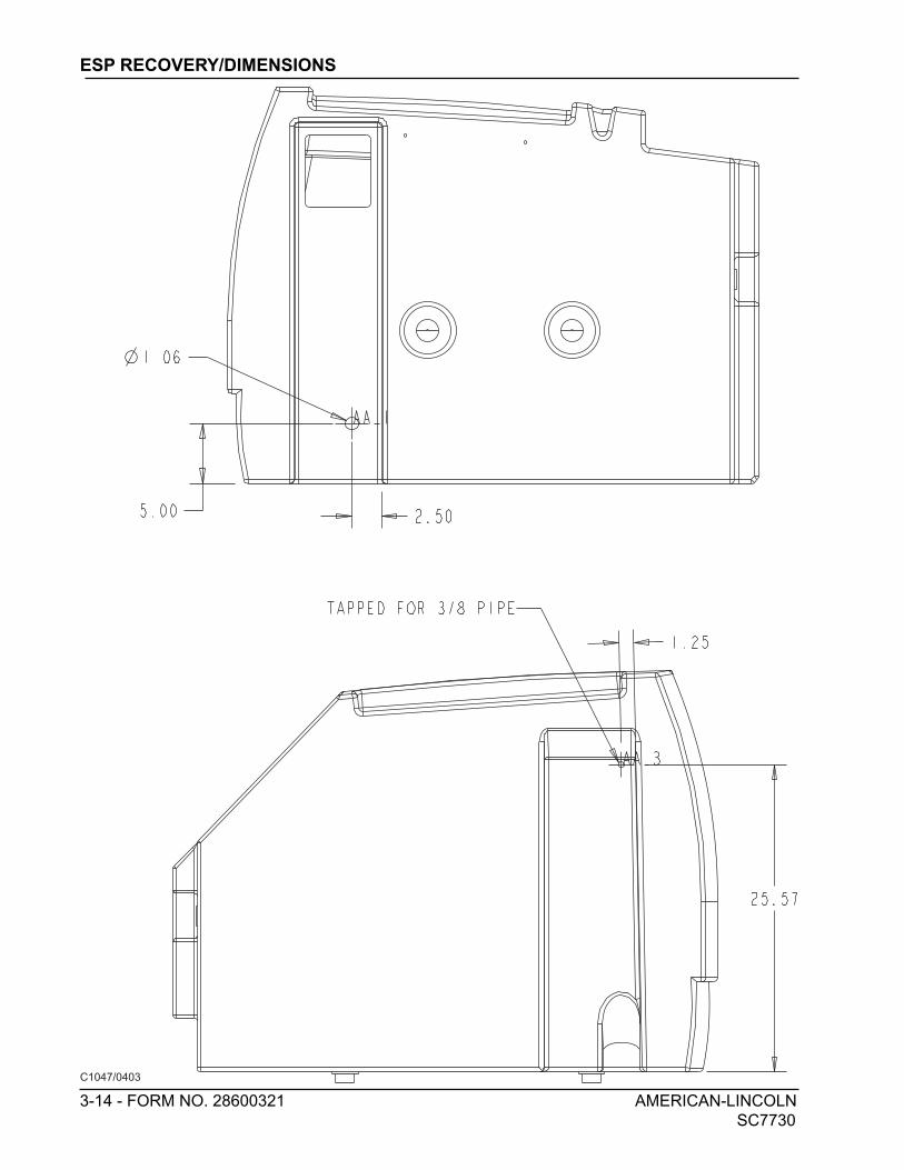
3-14 - FORM NO. 28600321 AMERICAN-LINCOLN
SC7730
C1047/0403
ESP RECOVERY/DIMENSIONS
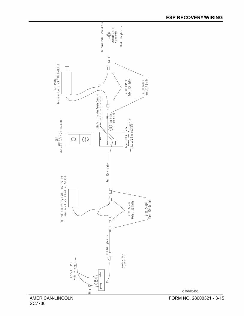
AMERICAN-LINCOLN FORM NO. 28600321 - 3-15
SC7730
C1048/0403
ESP RECOVERY/WIRING

3-16 - FORM NO. 28600321 AMERICAN-LINCOLN
SC7730
SPRAY & VACUUM WAND OPTION
OPTION 0780-592
KEY NO. QTY PART NUMBER DESCRIPTION
1 1 7-08-00769 BRACKET, HOSE CONNECTION
2 1 2-00-00221 HEX BOLT, FIN., 1/4-20 x 3/4 LG
3 1 2-00-00518 LOCK WASHER, 1/4 HEL. SPRNG
4 1 2-00-00594 HEX NUT, 1/4-20
5 1 2-00-05465 ADAPTER, 1/4 FEMALEx1/8 MALE
6 1 2-00-05464 ELBOW 1/4 x BARB FITTING 3/8
7 2 2-00-00415 WASHER, .94 ID x .47 OD x .062
8 1 7-16-05028 COUPLING, QUICK DISCONNECT
9 4 2-00-05363 CLAMP, HOSE
10 1 7-60-05017 PUMP, WATER (36 VDC)
11 2 2-00-05201 FITTING
12 1 7-25-02052 FITTING, 3/4 PIPE x 3/4 BARB STR.
13 1 7-25-02037 FITTING, PLASTIC TEE
14 1 2-00-04655 FITTING, 90° NYLON ELBOW
15 1 7-25-02053 ELBOW, 90°, 3/4 NPT TO 3/4 BARB
16 3 2-00-03407 CLAMP, HOSE (WITTECK #10P)
17 4 2-00-01951 BOLT, CAR., 1/4-20 x 1.25 LG
18 4 2-00-03702 WASHER, .625 x .281 x .063
19 4 2-00-00641 NUT, FIBER INSERT 1/4-20
20 1 2-00-05869 GASKET, SWITCH
21 1 2-00-05827 SWITCH BODY
22 1 2-00-05839 ACTUATOR, SPRAY & VAC
23 1 7-18-00278 DECAL, VAC WAND
24 1 3-71-00135 HOSE, SOLUTION FEED
25 2 3-71-00081 HOSE, 3/8” ID x 36” OD
c1044/0403
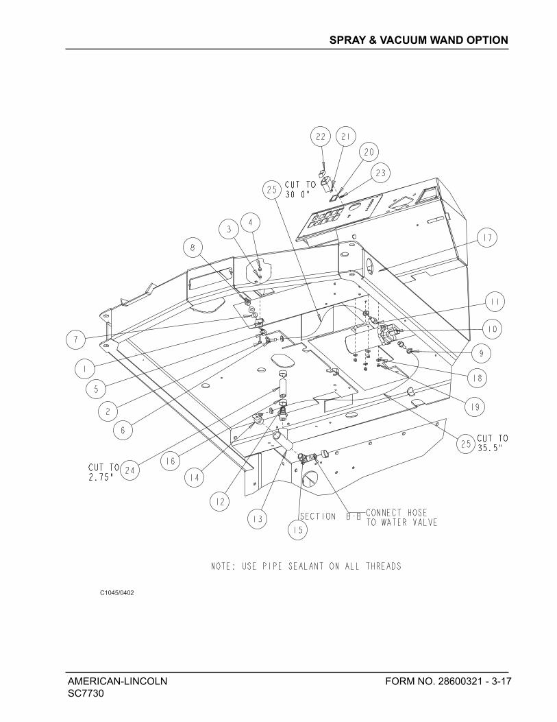
AMERICAN-LINCOLN FORM NO. 28600321 - 3-17
SC7730
C1045/0402
SPRAY & VACUUM WAND OPTION

3-18 - FORM NO. 28600321 AMERICAN-LINCOLN
SC7730
C1045/0403
SPRAY & VACUUM WAND CON’T.
KEY NO. QTY PART NUMBER DESCRIPTION
1 1 0261-029 HOSE ASSEMBLY
2 1 7-03-00044 ADAPTER, TRANSITION
3 1 639804 WAND ASSEMBLY
4 1 638828 TOOL ASSEMBLY
5 2 7-13-07140 CLAMP, HOSE
6 1 7-33-02306 HOSE, SOLUTION FEED
7 2 2-00-05207 ADAPTER, HOSE, 1/4 x 1/8 NPT
8 2 2-00-05206 REDUCER, MALE PIPE, 1/4 x 1/8
9 1 7-88-00058 VALVE, SOLUTION 1/4 NPT
10 2 7-13-07139 CLAMP, VALVE
11 1 8-56-05026 ELBOW, 45° STREET
12 1 7-16-05028 COUPLING, QUICK DISCONNECT
13 2 2-00-00089 SCREW, RHM 10-24 x 1.5 LG
14 2 2-00-01246 NUT, ELASTIC STOP #10-24
15 1 2-00-05208 ADAPTER, PIPE, 1/8 BRASSE
16 1 7-50-01002 SPRAY NOZZLE
c1045/0403
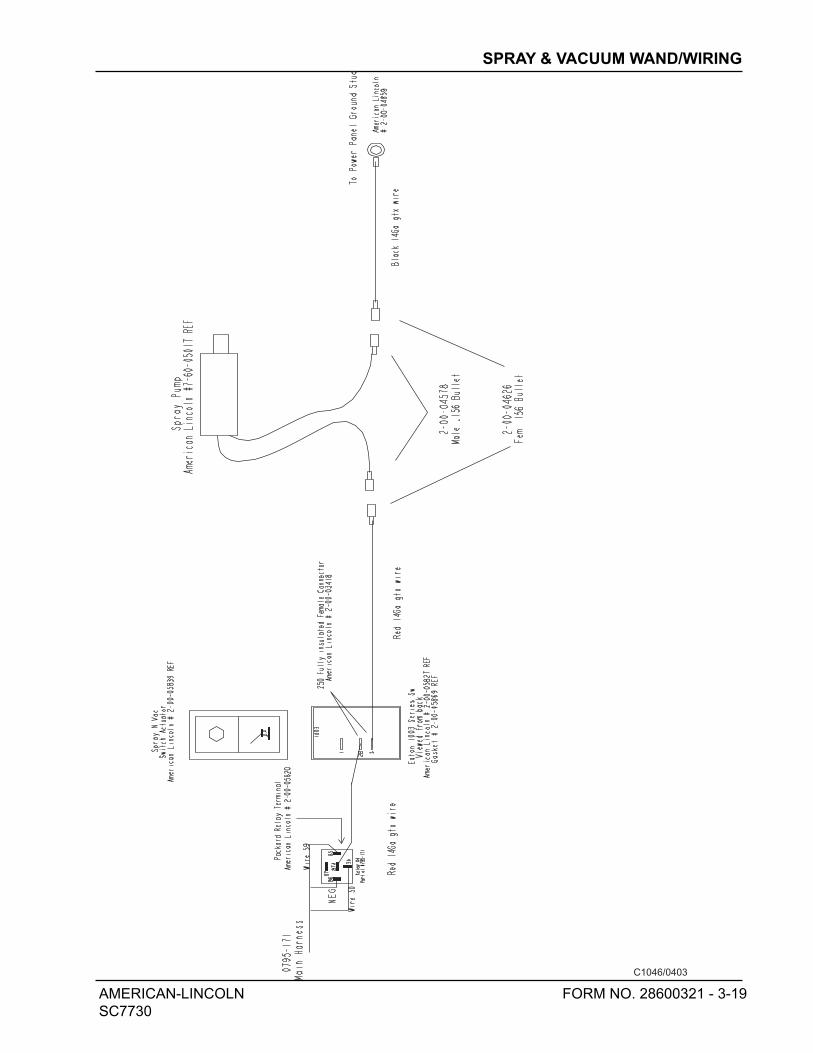
AMERICAN-LINCOLN FORM NO. 28600321 - 3-19
SC7730
C1046/0403
SPRAY & VACUUM WAND/WIRING
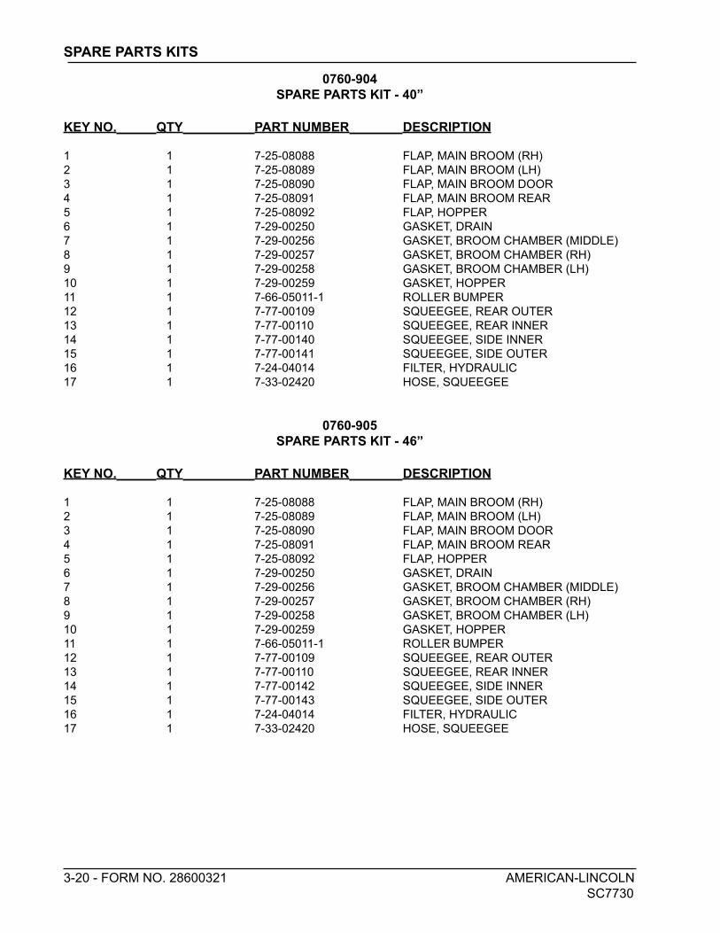
3-20 - FORM NO. 28600321 AMERICAN-LINCOLN
SC7730
0760-904
SPARE PARTS KIT - 40”
KEY NO. QTY PART NUMBER DESCRIPTION
1 1 7-25-08088 FLAP, MAIN BROOM (RH)
2 1 7-25-08089 FLAP, MAIN BROOM (LH)
3 1 7-25-08090 FLAP, MAIN BROOM DOOR
4 1 7-25-08091 FLAP, MAIN BROOM REAR
5 1 7-25-08092 FLAP, HOPPER
6 1 7-29-00250 GASKET, DRAIN
7 1 7-29-00256 GASKET, BROOM CHAMBER (MIDDLE)
8 1 7-29-00257 GASKET, BROOM CHAMBER (RH)
9 1 7-29-00258 GASKET, BROOM CHAMBER (LH)
10 1 7-29-00259 GASKET, HOPPER
11 1 7-66-05011-1 ROLLER BUMPER
12 1 7-77-00109 SQUEEGEE, REAR OUTER
13 1 7-77-00110 SQUEEGEE, REAR INNER
14 1 7-77-00140 SQUEEGEE, SIDE INNER
15 1 7-77-00141 SQUEEGEE, SIDE OUTER
16 1 7-24-04014 FILTER, HYDRAULIC
17 1 7-33-02420 HOSE, SQUEEGEE
0760-905
SPARE PARTS KIT - 46”
KEY NO. QTY PART NUMBER DESCRIPTION
1 1 7-25-08088 FLAP, MAIN BROOM (RH)
2 1 7-25-08089 FLAP, MAIN BROOM (LH)
3 1 7-25-08090 FLAP, MAIN BROOM DOOR
4 1 7-25-08091 FLAP, MAIN BROOM REAR
5 1 7-25-08092 FLAP, HOPPER
6 1 7-29-00250 GASKET, DRAIN
7 1 7-29-00256 GASKET, BROOM CHAMBER (MIDDLE)
8 1 7-29-00257 GASKET, BROOM CHAMBER (RH)
9 1 7-29-00258 GASKET, BROOM CHAMBER (LH)
10 1 7-29-00259 GASKET, HOPPER
11 1 7-66-05011-1 ROLLER BUMPER
12 1 7-77-00109 SQUEEGEE, REAR OUTER
13 1 7-77-00110 SQUEEGEE, REAR INNER
14 1 7-77-00142 SQUEEGEE, SIDE INNER
15 1 7-77-00143 SQUEEGEE, SIDE OUTER
16 1 7-24-04014 FILTER, HYDRAULIC
17 1 7-33-02420 HOSE, SQUEEGEE
SPARE PARTS KITS

AMERICAN-LINCOLN 3-21
SC7730

14600 21st Avenue NorthPlymouth, MN 55447-3408www.americanlincoln.comPhone: 800-331-7692Fax: 877-877-2586©2006 American-Lincoln