Kontrol Otomatis - 1st Week
24
Chapter 1: Introduction to Control Systems
-
Upload
bakhtiyar-sierad -
Category
Documents
-
view
93 -
download
7
description
Kontrol Otomatis, Pens, EEPIS, POliteknik Elektronika Negeri Surabaya
Transcript of Kontrol Otomatis - 1st Week
Chapter 1: Introduction to Control Systems
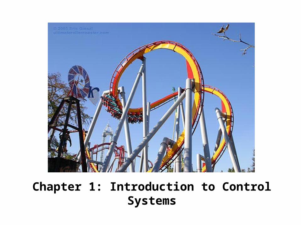
Chapter Objectives
At the end of this chapter, you will be able to:
• Identify the applications of control system
• Identify the basic features and configurations of control system
• List the design objectives of control system
• List the design process of control system
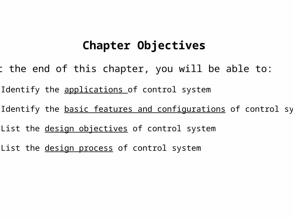
CONTROL SYSTEMS DEFINITION
Control Systems: collections of subsystems/components
Input: reference value/actuation signal/set point
Output: measured response/actual result
CONTROL SYSTEMS DEFINITION…..
A Control System consists of subsystems and processes (or plants) assembled for the purpose of controlling the outputs of the processes.
For example, a furnace produces heat as a result of the flow of fuel. In this process, subsystems called fuel valves and fuel-valve actuators are used to regulate the temperature of a room by controlling the heat output from the furnace. Other subsystems, such as thermostats, which act as sensor, measure the room temperature.
In its simplest form, a control system provides an output or response for a given input or stimulus.
ADVANTAGES OF CONTROL SYSTEMS
With Control Systems, we can move large equipment with precision that would otherwise be impossible. We can point huge antennas toward the farthest reaches of the universe to pick up faint radio signals; controlling these antennas by hand would be impossible.
Because of control systems, elevators carry us quickly to our destination, automatically stopping at the right floor. We alone could not provide the power required for the load and the speed; motors provide the power and control systems regulate the position and speed.
ADVANTAGES OF CONTROL SYSTEMS…..
We build Control Systems for four primary reasons:
1. Power AmplificationA radar antenna, positioned by the low-power rotation of a knob at the input, requires a large amount of power for its output rotation. A Control System can produce the needed power amplification, or power gain.
2. Remote ControlRobots designed by Control System principles can compensate for human disabilities. Control Systems are useful in remote or dangerous locations. For example, a remote-controlled robot arm can be used to pick up material in a radioactive environment.
ADVANTAGES OF CONTROL SYSTEMS…..
3. Convenience of Input FormControl Systems can also be used to provide convenience by changing the form of the input. In a temperature control system, the input is a position on a thermostat. The output is heat. Thus, a convenient position input yields a desired thermal output.
4. Compensation for DisturbancesConsider an antenna system that points in a commanded direction. If wind forces the antenna from its commanded position, or if noise enters internally, the system must be able to detect the disturbance and correct the antenna’s position.
Control System Configurations
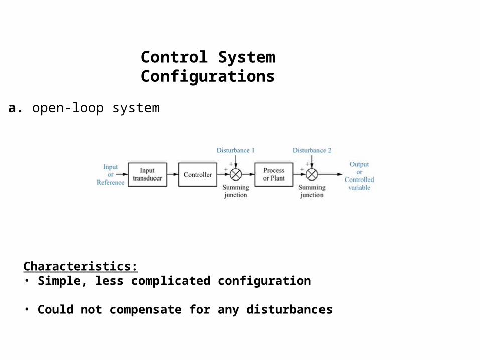
a. open-loop system
Characteristics:• Simple, less complicated configuration
• Could not compensate for any disturbances
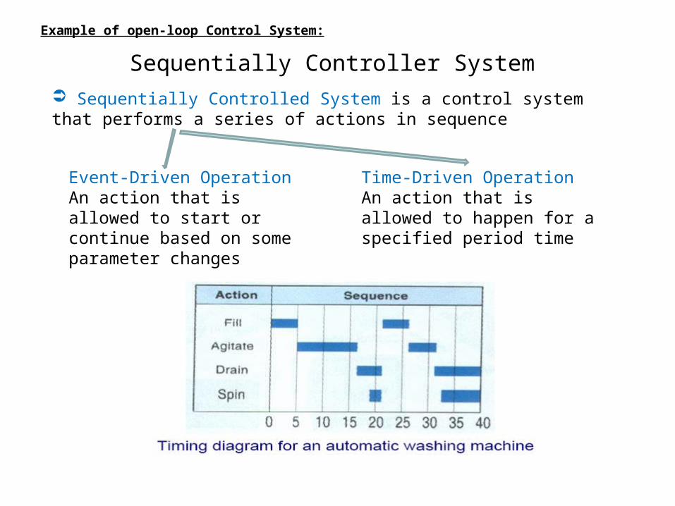
Example of open-loop Control System:
Sequentially Controller System Sequentially Controlled System is a control system that performs a series of actions in sequence
Event-Driven OperationAn action that is allowed to start or continue based on some parameter changes
Time-Driven OperationAn action that is allowed to happen for a specified period time
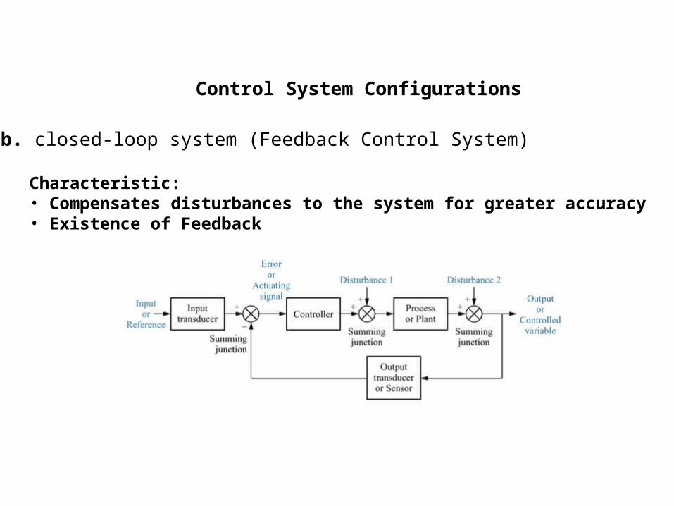
Control System Configurations
b. closed-loop system (Feedback Control System)
Characteristic:• Compensates disturbances to the system for greater accuracy• Existence of Feedback
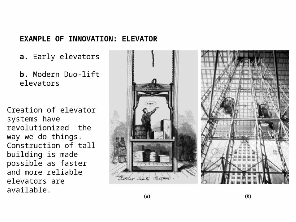
EXAMPLE OF INNOVATION: ELEVATOR
a. Early elevators
b. Modern Duo-liftelevators
Creation of elevator systems have revolutionized the way we do things. Construction of tall building is made possible as faster and more reliable elevators are available.
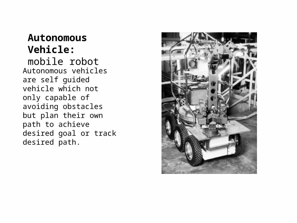
Autonomous Vehicle:mobile robot
Autonomous vehicles are self guided vehicle which not only capable of avoiding obstacles but plan their own path to achieve desired goal or track desired path.
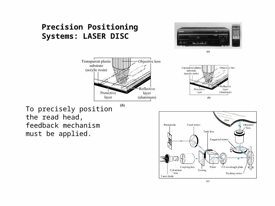
Precision Positioning Systems: LASER DISC
To precisely position the read head, feedback mechanism must be applied.

Feedback Systems:positioning of hard disk read head
Closed loop systems: Use the measured position to as compared to the desired position to modify the actuator signal.
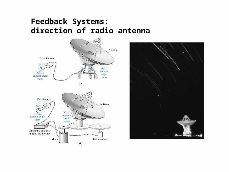
Feedback Systems:direction of radio antenna
Analysis and Design Objectives
A control system is dynamicIt responds to an input by undergoing a transient
response before reaching a steady-state response that generally resembles the input.
Objectives of system analysis and design:• Producing the desired transient response• Reducing steady state error• Achieving stability
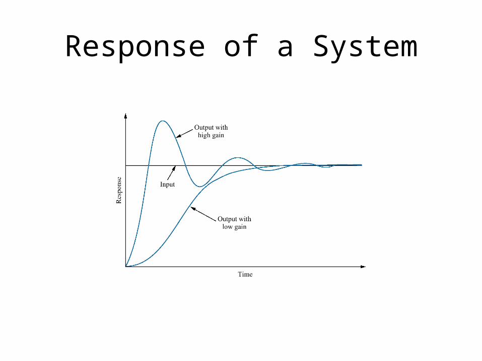
Response of a System
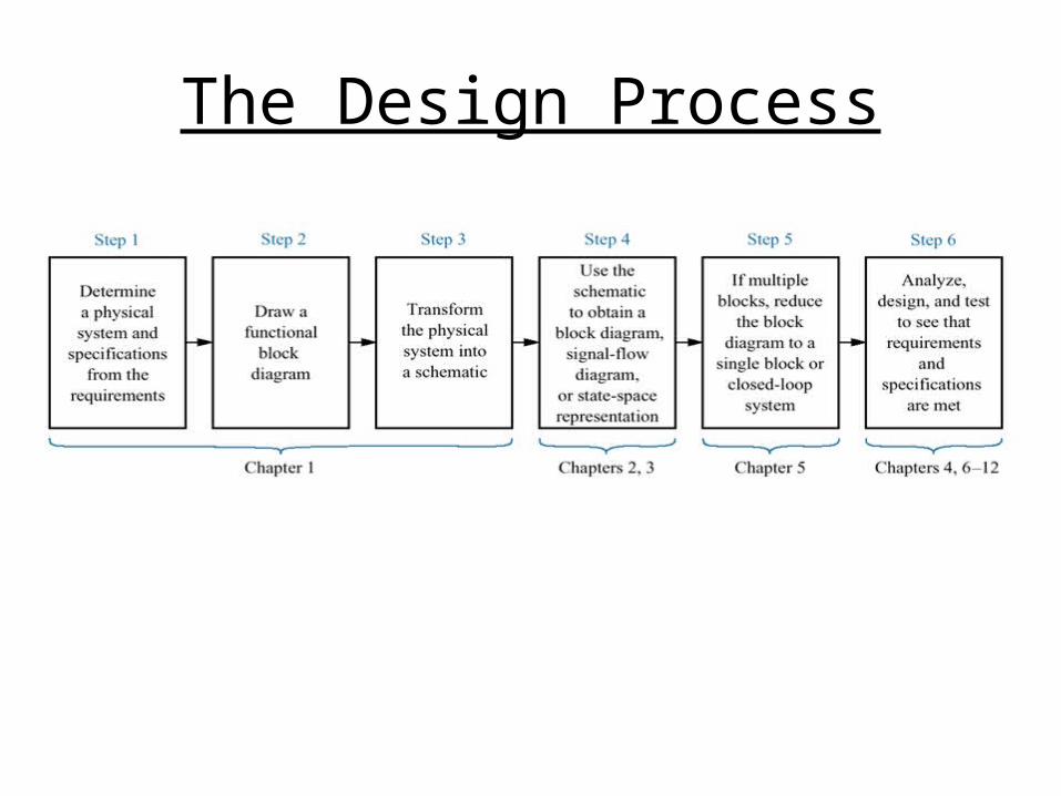
The Design Process
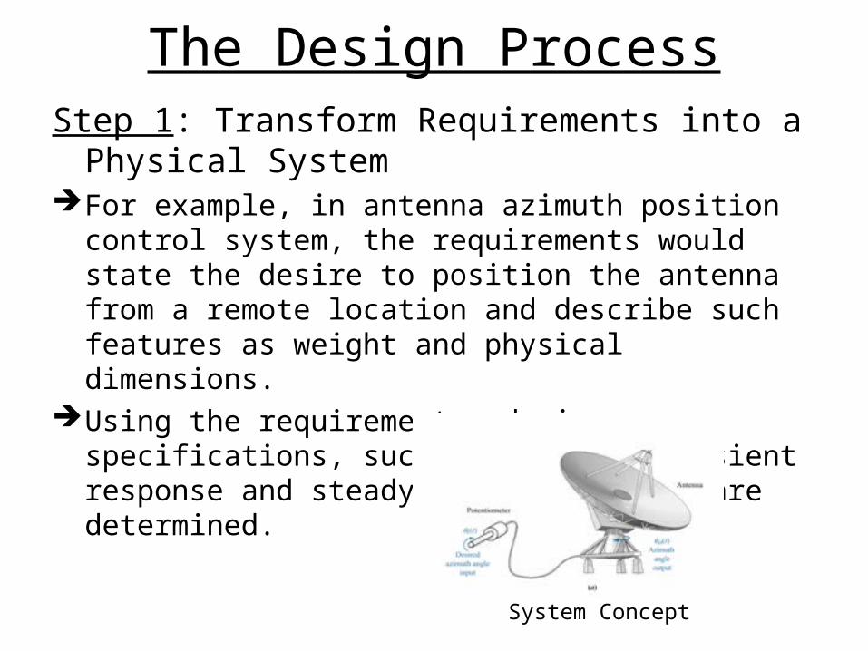
The Design ProcessStep 1: Transform Requirements into a Physical
SystemFor example, in antenna azimuth position control
system, the requirements would state the desire to position the antenna from a remote location and describe such features as weight and physical dimensions.
Using the requirements, design specifications, such as desired transient response and steady-state accuracy, are determined.
System Concept
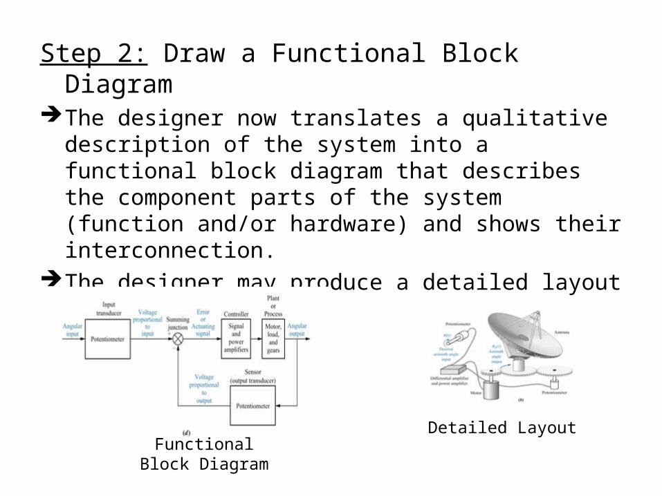
Step 2: Draw a Functional Block DiagramThe designer now translates a qualitative description of
the system into a functional block diagram that describes the component parts of the system (function and/or hardware) and shows their interconnection.
The designer may produce a detailed layout of the system.
Functional Block Diagram
Detailed Layout
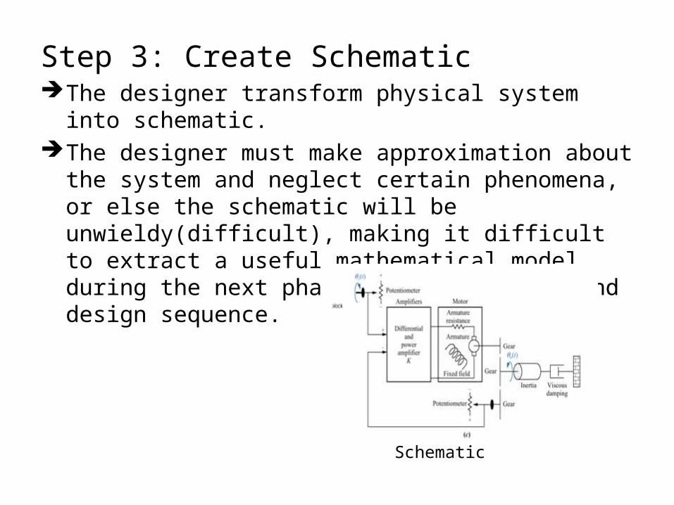
Step 3: Create SchematicThe designer transform physical system into schematic.The designer must make approximation about the
system and neglect certain phenomena, or else the schematic will be unwieldy(difficult), making it difficult to extract a useful mathematical model during the next phase of the analysis and design sequence.
Schematic
Step 4: Develop a Mathematical Model (Block Diagram)
Once the schematic is drawn, the designer uses physical laws, such as Kirchhoff’s laws for electrical networks and Newton’s laws for mechanical systems, along with simplifying assumptions, to model the system mathematically.
To produce the mathematical model for a system, we require knowledge of the parameters values, such as equivalent resistance, inductance, mass, and damping, which is not easy to obtain.
The mathematical model can be represent in Differential Equation, Transfer Function, or State Space.
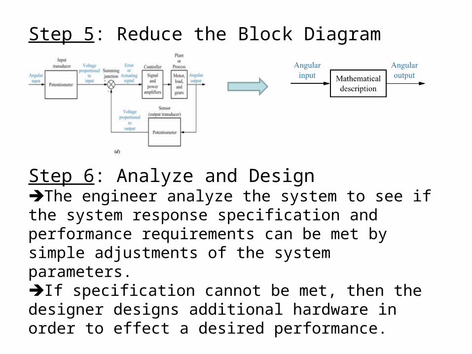
Step 5: Reduce the Block Diagram
Step 6: Analyze and DesignThe engineer analyze the system to see if the system response specification and performance requirements can be met by simple adjustments of the system parameters.If specification cannot be met, then the designer designs additional hardware in order to effect a desired performance.
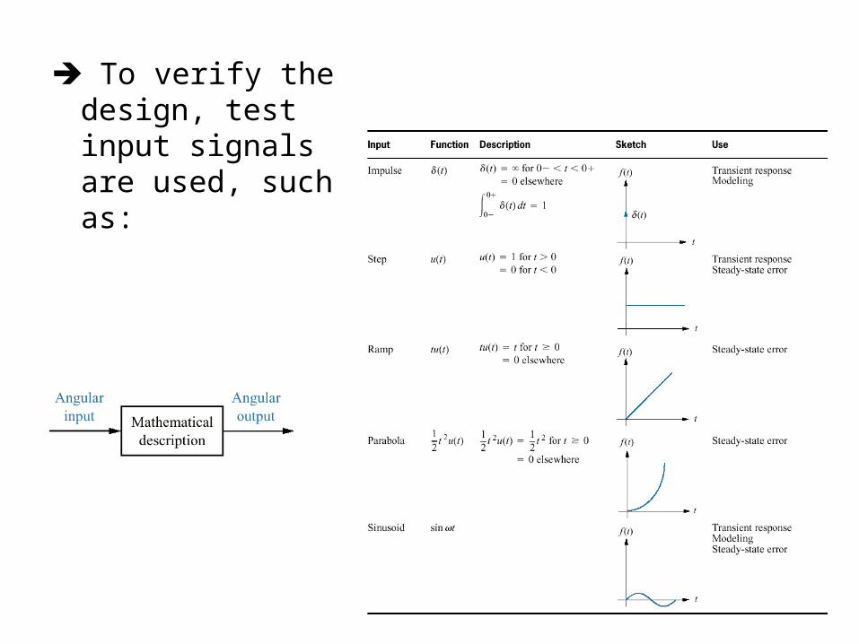
To verify the design, test input signals are used, such as: