(Jn4 lECHNICAL INFORMATION BUllETIN · PDF fileff)rn ;1;~ p~ (jn4 lechnical information...
2
ff)rn (Jn4 lECHNICAL INFORMATION BUllETIN MANNED SPACE. FLIGHT NETWORK GODDARD SPACE FLIGHT CENTER, GREENBELT, MARYLAND Vol.1 No.15 NATIONAL AERONAUTICS AND SPACE ADMINISTRATION Sep, tember 20, 1963 TDF Being Added To Timing System Unlike s' ome systems which must undergo extensive modifications to sup- port Gemini, the timing system is being altered very little. The extent of its alteration is the addition of a timing distribution frame (TDF). o In most cases the TDF is being installed next to the present two racks of Mercury tme standard equipm ent in the P A M/FM/ 1"M telemetry area. It contains input isolation and GMT binary-coded-decimal (BCD) output amplifiers, a GMT BCD-to- decimal converter, input isolation and serial-decimal time output amplifiers, a Gemini ground elapsed time (GGET) clock, an Agena ground elapsed time (AGET) clock, and four power supplies. The TDF distributes: GGET and AG ET signals after counting and conver- sion to decimal format of the one-per- second pulse from the Mercury time standard; GMT in unitary decimal after converting it from the 20 bits of GMT in binary code decimal (BCD); and BCD. The GGET and AGET clocks are bi- directional devices that read from -999:59 to +999:59:59. Through their displays on the TDF and other consoles, they provide a display of the countdown time of the Gemini and Agena vehicles I"'""' nd continue to provide a display of time -, lapsed after launch. Solid-state circuitry is used in the Sig- nal processing circuits for driving the console clock displays, in the two regu- lated power supplies provided for clock circuitry, and in the two unregulated power supplies for relays. 20 BITS BCD GMT I PULSE PER - SECOND } 4 OUTPUT CONNECTORS FOR GMT (UD) Clock functions can be controlled from the M&O console and the TDF. Both local and remote clock switching is performed by hermetically sealed relays. Stations presently designated to re- ceive the TDF include TEX, RKV, CNV, CRO, CYI, HAW, GYM, CSQ, IMCC, and WLP. About EI's The following Engineering Instructions have been issued during the past two weeks: EI603A PCM/FM-FM/Recorder Inter- face (RKV) EI 605 RKV, CSQ PCM Implementation EI609 PCM Implementation (CYI, HAW, GYM, TEX, WLP) EI PCM Implementation (CRO) EI 613 PCM Implementation (BDA) EI614 t/ EI615 ,/ EI617 EI618 t/ FM - FM Telemetry Installation (CRO) DC/DC Converter Switching (All stations except GBI, GTI) Magnecorder Recorder Modifi- cation (All stationS except GBI, GTI, WOM, WHS, EGL) Relocation of HF /UHF Master / Standby Remote Switch (All sta- tions except WOM, WHS, EGL) GMT I DAYS HOURS MIN SEC I 00 GGET Block diagram depict- I HOURS MIN SEC 1 0 ing data flow of the 000 0 0 0 0 TDF AGET • I HOURS MIN SEC 1 0 o 0 0 0 0 0 0 } 4 OUTPUT CONNECTORS FOR GMT ( BCD) } 4 OUTPUT CONNECTORS FOR GGET } 4 OUTPUT CONNECTORS FOR AGET Drawing of TDF's front panel • REGULATED VOLTAGE 1 -' /"-1 1 -" )"1 UNREGULAITO VOLTAGE 1 -" )' -1 1") -- 1 Network To Support Saturn Portions of the Manned Space Flight Network and the STADAN (Satellite Tracking and Data Acquisition Network- former ly Minitrack) will be supported by the SAO (Smithsonian Astrophysical Observatory) network and elements of the DOD National Ranges in forming an integrated global tracking network to support the Saturn SA-5 orbital flight during the last quarter of the current year. Amongthe initial stations to be involved are CNV, BDA, MUC, HAW, CAL, GYM , WHS, and TEX. Support will conSist of telemetry recording for two orbits and skin-tracking with C-band radar for an indefinite period. The precount , count- down, and first two orbits will be treated in a manner similar to the Mercury / Atlas missions, with the network under the control of a Network Director at the Space Operations Control Center at GSFC. A/G voice, S-band radar , and command subsystems will not be re- quired, but otherwise, standard operat- ing procedures will be used. Radar data will be transmitted to GSFC in real time , and the regular voice communications network will be used. The S-IV second stage, the instru- mentation unit, and the dummy payload are expected to be placed in an orbit of approximately 260 KM perigee, 650 KM apogee, and should give the FPS-16's a pretty good target. The telemetry beacon is not programmed to last longer than two orbits; after this time look- angle data will be computed at GSFC and updated daily for stations called up on an individual basis. A Minitrack beacon will permit the STADAN stations to continue tracking and supply the computers with additional data for up- dating the look angles for up to 45 days. This is the first of many projects in which it is expected to combine the re- sources of the MSF Network with those of other stations in furtherance of the overall space effort. **************
Transcript of (Jn4 lECHNICAL INFORMATION BUllETIN · PDF fileff)rn ;1;~ p~ (jn4 lechnical information...
ff)rn ;1;~ p~ (Jn4
lECHNICAL INFORMATION BUllETIN MANNED SPACE. FLIGHT NETWORK
GODDARD SPACE FLIGHT CENTER, GREENBELT, MARYLAND
Vol.1 No.15 NATIONAL AERONAUTICS AND SPACE ADMINISTRATION Sep,tember 20, 1963
TDF Being Added To Timing System Unlike s'ome systems which must
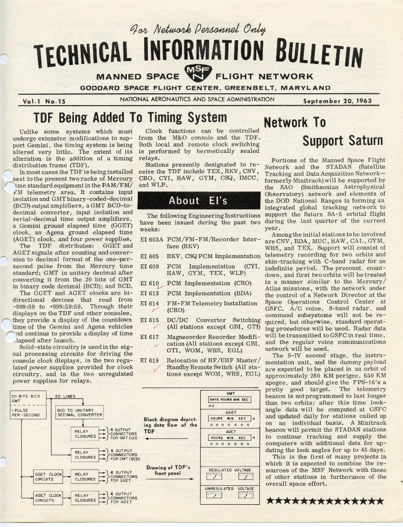
undergo extensive modifications to support Gemini, the timing system is being altered very little. The extent of its alteration is the addition of a timing distribution frame (TDF).
o In most cases the TDF is being installed next to the present two racks of Mercury tme standard equipm ent in the P A M/FM/
1"M telemetry area. It contains input isolation and GMT binary-coded-decimal (BCD) output amplifiers, a GMT BCD-todecimal converter, input isolation and serial-decimal time output amplifiers, a Gemini ground elapsed time (GGET) clock, an Agena ground elapsed time (AGET) clock, and four power supplies.
The TDF distributes: GGET and AG ET signals after counting and conversion to decimal format of the one-persecond pulse from the Mercury time standard; GMT in unitary decimal after converting it from the 20 bits of GMT in binary code decimal (BCD); and BCD.
The GGET and AGET clocks are bi-directional devices that read from -999:59 to +999:59:59. Through their displays on the TDF and other consoles, they provide a display of the countdown time of the Gemini and Agena vehicles
I"'""'nd continue to provide a display of time -,lapsed after launch.
Solid-state circuitry is used in the Signal processing circuits for driving the console clock displays, in the two regulated power supplies provided for clock circuitry, and in the two unregulated power supplies for relays.
20 BITS BCD GMT
I PULSE PER - SECOND
}
4 OUTPUT CONNECTORS FOR GMT (UD)
Clock functions can be controlled from the M&O console and the TDF. Both local and remote clock switching is performed by hermetically sealed relays.
Stations presently designated to receive the TDF include TEX, RKV, CNV, CRO, CYI, HAW, GYM, CSQ, IMCC, and WLP.
About EI's The following Engineering Instructions
have been issued during the past two weeks:
EI603A PCM/FM-FM/Recorder Interface (RKV)
EI 605 RKV, CSQ PCM Implementation
EI609 PCM Implementation (CYI, HAW, GYM, TEX, WLP)
EI 61~ PCM Implementation (CRO)
EI 613 PCM Implementation (BDA)
EI614 t/
EI615 ,/
EI617
EI618
t/
FM - FM Telemetry Installation (CRO)
DC/DC Converter Switching (All stations except GBI, GTI)
Magnecorder Recorder Modification (All stationS except GBI, GTI, WOM, WHS, EGL)
Relocation of HF /UHF Master / Standby Remote Switch (All stations except WOM, WHS, EGL)
GMT
I DAYS HOURS MIN SEC I 00
GGET
Block diagram depict- I HOURS MIN SEC 10
ing data flow of the 000 0 0 0 0
TDF AGET
• I HOURS MIN SEC 10
o 0 0 0 0 0 0
}
4 OUTPUT CONNECTORS FOR GMT ( BCD)
}
4 OUTPUT CONNECTORS FOR GGET
}
4 OUTPUT CONNECTORS FOR AGET
Drawing of TDF's front panel
• REGULATED VOLTAGE
1-' /"-1 1-" ) "1 UNREGULAITO VOLTAGE
1-")' -1 1" ) --1
Network To Support Saturn
Portions of the Manned Space Flight Network and the STADAN (Satellite Tracking and Data Acquisition Networkformer ly Minitrack) will be supported by the SAO (Smithsonian Astrophysical Observatory) network and elements of the DOD National Ranges in forming an integrated global tracking network to support the Saturn SA-5 orbital flight during the last quarter of the current year.
Amongthe initial stations to be involved are CNV, BDA, MUC, HAW, CAL, GYM , WHS, and TEX. Support will conSist of telemetry recording for two orbits and skin-tracking with C-band radar for an indefinite period. The precount , countdown, and first two orbits will be treated in a manner similar to the Mercury / Atlas missions, with the network under the control of a Network Director at the Space Operations Control Center at GSFC. A/G voice, S-band radar , and command subsystems will not be required, but otherwise, standard operating procedures will be used. Radar data will be transmitted to GSFC in real time , and the regular voice communications network will be used.
The S-IV second stage, the instrumentation unit, and the dummy payload ar e expected to be placed in an orbit of approximately 260 KM perigee, 650 KM apogee, and should give the FPS-16's a pretty good target. The telemetry beacon is not programmed to last longer than two orbits; after this time lookangle data will be computed at GSFC and updated daily for stations called up on an individual basis. A Minitrack beacon will permit the STADAN stations to continue tracking and supply the computers with additional data for updating the look angles for up to 45 days.
This is the first of many projects in which it is expected to combine the resources of the MSF Network with those of other stations in furtherance of the overall space effort.
**************
Correction It has been brought to the attention of
TIE by numerous readers that the last issue included some incorrect information. Thevolume number should have read No. 14 and the date, Sept em ber 6, 1963; also the block diagram of the RF command should have shown the dummy loads as 500 W instead of 50 W, and the antenna inputs as 10 KW instead of 15 KW. The past editor of TIE feels very bad about these mistakes.
New Forms To Be Used Pads of Change Recommendation Re
port, Form MP-523, have been forwarded to all stations to take the place of two currently used forms: Product Improvement Report, Form MP-225A, and Local ModificationReport, Form MP-l\OO. The new form is designed to facilitatelprocessing of site-originated recommelations for improvements to equipment, procedures, and docmnentation. eneral instructions for the use of MPl,I'23 are printed on the back of the form; etailed instructions will be included in ~twork Operations Directive 63-1. Add\tional quantities of the form (and all other MP forms) may be requested by tele~ype message to UNV /Bell, stating the form number and the quantity desired. (NASA stations may use standard depot requisitioning procedures.)
Recommendations for local modifications are encouraged as part of the overall Network Product Improvement Program, but the following ground rules (as stated in OD 61-1) must be followed in making actual changes to the equipment.
1. No permanent modification to MSF Network C&E equipment will be made without approval of GSFC.
2. Temporary modifications made to equipment while awaiting GSFC approval must be of such a nature that the equipment can be returned to its original state within 24 hours in the event the modification is not approved.
The Change Recommendation Report should now be the vehicle for requesting approval for such local modifications. GSFC will analyze each report in light of its effect on present and planned equipment, and study its applicability to other stations. If the modification is deemed applicable to the originating station only, that station will be notified by TWX that the modification is approved. If it is found to be a desirable feature for more than one station, an EI will be issued to implement it at all applicable stations. If the modification is determined to be undesirable, the originating station will be so notified, and the equipment will be returned to its original condition.
e following documents were completed and distributed to the appropriate stations:
ME-101 Radar Tracking System, ReviV sion July 1, 1963
ME-10.yX-Y Recorder, Revision Au../ gust 16, 1963
ME-144 Preamplifier Model PR-203, Revision July 29, 1963
ME - 404 Data Receiver Model 4008- 2B, Revision July 22, 1963
ME-405 Digital-to-Tele~e Converter, r/ Revision July 15, 1963
ME-458 Sanborn Special Panel Model 862-500-E3975, Revision Au gust 15, 1963
ME-1049 Sideband Converter Model TMC, SBG-10r SBG-2 (new)
ME - 1052 Recording System Model 958C (new)
ME- 1053 AC-to-DC Converters, Series t/ 125 (new)
ME - 1054 Telemetering Signal Generator ./ Type 202J (new)
ME-12P5
The first issue of the MSFN Engine ing ~ingRecord (TIE, July 12th was completoo'lmE:l-digributed to the two r k stations on AuguSt2 . he second issue of the record is now practically complete and is expected to be distributed by September 24th. Hard-back binders and colored dividers on heavy paper have been obtained and will be shipped along with the second issue. These binders and colored dividers should make the record a good deal handier to use .
Beginning with the third issue, in October, the record will be published on a regular monthly basis. It will be brought up to date as of the 15th of each month and will be completed and distributed within four or five working days thereafter.
Students Complete Gemini In-Plant
Training Courses Today, sixty-one students complete the
Gemini in-plant training courses: 34 complete the PCM course at EMR, Sarasota, F lorida; and 27 complete the DCS course at Radiation, Inc., Melbourne , Florida. Both courses were five weeks in duration, covering 200 hours. P ersonnel will now return to their respective stations and prepare for installation of the two systems .
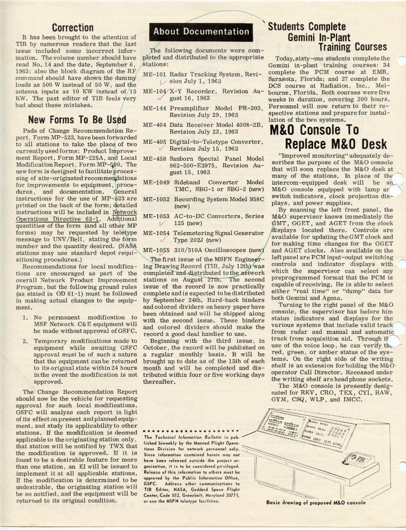
M&O Console To Replace M&O Desk
"Improved monitoring" adequately describes the purpose of the M&O console that will soon replace the M&O desk at many of the stations. In place of the /' intercom -equipped desk will be an M&O console equipped with lamp anrswitch indicators, clock projection displays, and power supplies.
By scanning the left front panel, the &0 supervisor knows immediately the MT, GGET, and AGET from the clock
isplays located there. Controls are available for updating the GMT clock and for making time changes for the GGET and AGET clocks. Also available on the left panel are PCM input-output switching
/"'\ controls and indicator displays with which the supervisor can select any preprogrammed format that the PCM is capable of receiving. He is able to select either "real time" or "dump" data for both Gemini and Agena.
Turning to the right panel of the M&O console, the supervisor has before him status indicators and displays for the various systems that include valid track ~ from radar and manual and automatic track from acquisition aid . Through U-----use of the voice loop, he can verify tht.- / red, green, or amber status of the systerns. On the right side of the writing shelf is an extension for holding the M&O ' operator Call Director. Recessed under the writing shelf are headphone sockets.
The M&O console is presently deSignated for RKV , CRO, TEX, CYI, HAW, GYM, CSQ, WLP , and IMCC.
It~===----;J~, ~ ~;~ :lJ',~<s~~o .;-, ...,/~~----'==-,
• •••••••••••••••••••• The Technical Infarmation B~lIetin is pub. lis hed biweekly by the Manned Flight Opera. t io ns Division for network personnel only.
Since information contained herein may not
hove been re lea sed outside the project or
ganization, it is to be considered privileged.
Relea se of this information to others must be
a ppro ved by the Publ ic Information Office, GSFC . Address other communications to TIB Editor, NASA, Goddard Space Flight Center, Code 552, Greenbelt, Maryland 20771, or use the MSFN teletype facilities .
~~ Qi __ o l <::. 11i:7 000 I ' lD$O'l 00 0 a 0 n ' II
. 'lfi:lli& 0 G ,.., .I r; ' -~000~ ... ;
___ ~ C..I ~/~
~-- ;/ -.,.~
C t .~i~~? -~
~ I[[~ Bas ic drawing of proposed M&O con so le