J001.059 PLH Küche 2015 Export en - vzug.com · 9 Wall hoods Product Product family DWPQ12 62006...
140
Planning aid Kitchen appliances 2015
Transcript of J001.059 PLH Küche 2015 Export en - vzug.com · 9 Wall hoods Product Product family DWPQ12 62006...
Planning aidKitchen appliances
2015
V-ZUG LtdV-ZUG Ltd, Industriestrasse 66, CH-6301 [email protected], www.vzug.com
Planning aidKitchen appliances
J001.059-R1404.05.15
2
Note on content
Please noteThis planning aid applies to the specified model numbers only. Older planning aids for earlier generation models may be requested inelectronic form from our Customer Services.
This planning aid is not to be used as installation instructions! The regulations and instructions binding for the appliance installationare to be obtained from the installation instructions packed with the appliances. The installation instructions can also be downloadedfrom the internet from www.vzug.com/b2b.
ModificationsText, diagrams and data correspond to the technical standard of the appliances at the time this planning aid went to press. The rightto make technical modifications for the purpose of the further development of the appliances is reserved.
Symbols used
Denotes important safety precautions.Failure to observe said precautions can result in injury or in damage to the appliance or fittings!
► Indicates an instruction.
• Indicates a list.
Information and precautions that should be observed.
Supplementary documentsIn this planning aid, occasional reference is made to supplementary documents. These documents can be requested from the HeadOffice in Zug by sending an e-mail to [email protected].
Useful links
• www.vzug.com
• www.vzug.com/b2b
• www.vzug.com/lifestyle
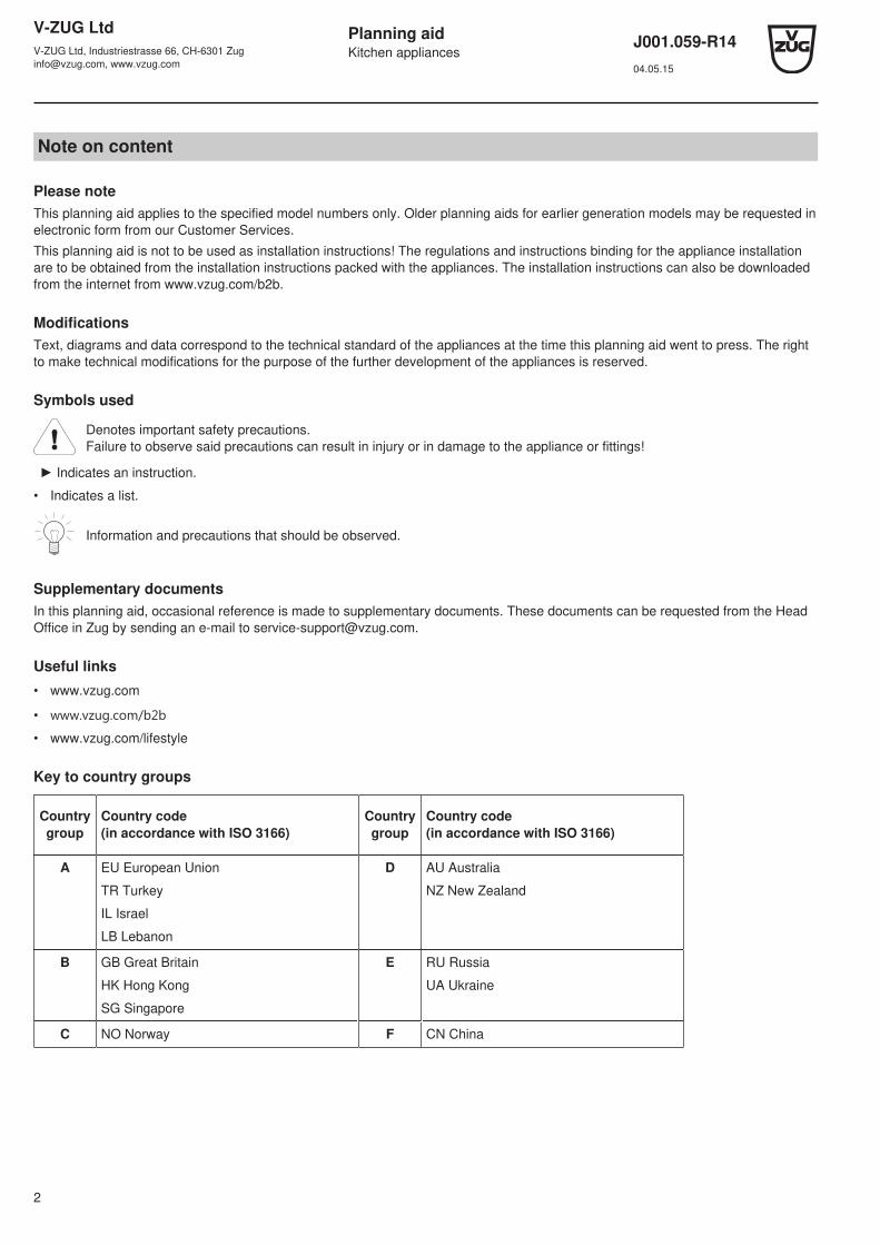
Key to country groups
Countrygroup
Country code (in accordance with ISO 3166)
Countrygroup
Country code (in accordance with ISO 3166)
A EU European Union
TR Turkey
IL Israel
LB Lebanon
D AU Australia
NZ New Zealand
B GB Great Britain
HK Hong Kong
SG Singapore
E RU Russia
UA Ukraine
C NO Norway F CN China
V-ZUG LtdV-ZUG Ltd, Industriestrasse 66, CH-6301 [email protected], www.vzug.com
Planning aidKitchen appliances
J001.059-R1404.05.15
3
Contents
1 Overview of connections, ranges and dimensions 51.1 General operating conditions.................................................................................................................................................... 51.2 Use of residual current devices (RCDs) in domestic installations / fault currents .................................................................... 51.3 Validity ...................................................................................................................................................................................... 61.4 Positions of electrical connections.......................................................................................................................................... 111.5 Built-in EURO ......................................................................................................................................................................... 121.6 Front dimensions of the appliances........................................................................................................................................ 13
2 Ovens 142.1 Electrical connection data....................................................................................................................................................... 142.2 Combair SL (21022), SE (21016), SLP (21025), SEP (21019) .............................................................................................. 142.3 Combair XSL (21023), XSE (21017), XSLP (21028), XSEP (21027)..................................................................................... 142.4 Combair HSE (21004) ............................................................................................................................................................ 15
3 Steam cookers 163.1 Electrical connection data....................................................................................................................................................... 163.2 Air circulation diagram for Combi-Steam MSLQ..................................................................................................................... 163.3 Combi-Steam MSLQ (23015) ................................................................................................................................................. 173.4 Combair-Steam SL (23012), SE (23010) ............................................................................................................................... 173.5 Combi-Steam HSL (23004), Steam HSE (23002) .................................................................................................................. 173.6 Combi-Steam XSL (23005) .................................................................................................................................................... 173.7 Combi-Steam XSLF (23007) .................................................................................................................................................. 18
4 Microwaves 214.1 Electrical connection data....................................................................................................................................................... 214.2 Miwell-Combi HSL (24008), XSL (24009), Miwell HSL (24006) ............................................................................................. 214.3 Miwell L (24002) ..................................................................................................................................................................... 22
5 Coffee-Centers 235.1 Electrical connection data....................................................................................................................................................... 235.2 Supremo HSL (25002)............................................................................................................................................................ 235.3 Supremo XSL (25003)............................................................................................................................................................ 23
6 Warming and system drawers 246.1 General notes ......................................................................................................................................................................... 246.2 Electrical connection data....................................................................................................................................................... 246.3 Warming drawers with niche width 60 cm .............................................................................................................................. 246.4 System drawers with niche width 60 cm................................................................................................................................. 27
7 Combination possibilities 287.1 Oven & mini oven & steam cooker 60 cm .............................................................................................................................. 287.2 Oven & microwave 60 cm....................................................................................................................................................... 297.3 Oven & coffee-center 60 cm................................................................................................................................................... 31
8 Glass ceramic hobs – induction, wok, teppanyaki 328.1 General notes ......................................................................................................................................................................... 328.2 Electrical connection data....................................................................................................................................................... 338.3 Ventilation............................................................................................................................................................................... 338.4 Framed installation ................................................................................................................................................................. 348.5 Flush installation..................................................................................................................................................................... 388.6 Installation without protective plate......................................................................................................................................... 448.7 Installation with protective plate.............................................................................................................................................. 468.8 Installing above oven / steam cooker ..................................................................................................................................... 48
9 Toptronic glass ceramic hobs 499.1 General notes ......................................................................................................................................................................... 499.2 Electrical connection data....................................................................................................................................................... 499.3 Framed installation ................................................................................................................................................................. 509.4 Flush installation..................................................................................................................................................................... 539.5 Installing above oven.............................................................................................................................................................. 57
10 Glass ceramic hobs for the replacement market 5810.1 Appliances for the replacement market – induction................................................................................................................ 5810.2 Appliances for the replacement market – Toptronic ............................................................................................................... 63
11 Examples for combined appliance installation 64

V-ZUG LtdV-ZUG Ltd, Industriestrasse 66, CH-6301 [email protected], www.vzug.com
Planning aidKitchen appliances
J001.059-R1404.05.15
4
12 Gas hobs & lava grills 6512.1 Gas hobs ................................................................................................................................................................................ 6512.2 Lava grill, GK11TKLG (98A) ................................................................................................................................................... 6812.3 2-zone induction hob, GK21TI (834) ...................................................................................................................................... 6812.4 Installation examples for combined gas edition arrangement................................................................................................. 69
13 Range hoods 7313.1 General notes ......................................................................................................................................................................... 7313.2 Ceiling range hoods................................................................................................................................................................ 7313.3 Island hoods ........................................................................................................................................................................... 7513.4 Wall hoods.............................................................................................................................................................................. 8013.5 Built-in hoods.......................................................................................................................................................................... 88
14 Refrigerators 9814.1 General notes ......................................................................................................................................................................... 9814.2 Electrical connection data....................................................................................................................................................... 9814.3 Ambient conditions ................................................................................................................................................................. 9814.4 Niche ventilation ..................................................................................................................................................................... 9914.5 Refrigerators ........................................................................................................................................................................... 9914.6 Winecoolers.......................................................................................................................................................................... 101
15 Dishwashers 10215.1 General notes ....................................................................................................................................................................... 10215.2 Electrical connection data / plumbing in ............................................................................................................................... 10315.3 Installation overview ............................................................................................................................................................. 10515.4 Drilling plans for decor panel 60 cm ..................................................................................................................................... 10615.5 Adora SL, S, N with niche width 60 cm ................................................................................................................................ 107
16 Dishwashers with heat pump 11216.1 General notes ....................................................................................................................................................................... 11216.2 Electrical connection data / plumbing in ............................................................................................................................... 11316.3 Installation summary............................................................................................................................................................. 11516.4 Drilling plans for decor panel 60 cm ..................................................................................................................................... 11516.5 Adora SL WP with niche width 60 cm................................................................................................................................... 116
17 Accessories 11917.1 Control set option (current sensor module with relay module) ............................................................................................. 11917.2 Cookers / ovens / steam cookers / microwaves / coffee machines / warming & systems drawers ...................................... 12017.3 Glass ceramic hobs .............................................................................................................................................................. 12217.4 Range hoods ........................................................................................................................................................................ 12417.5 Refrigerators ......................................................................................................................................................................... 13517.6 Dishwashers ......................................................................................................................................................................... 135
V-ZUG LtdV-ZUG Ltd, Industriestrasse 66, CH-6301 [email protected], www.vzug.com
Planning aidKitchen appliances
J001.059-R1404.05.15
5
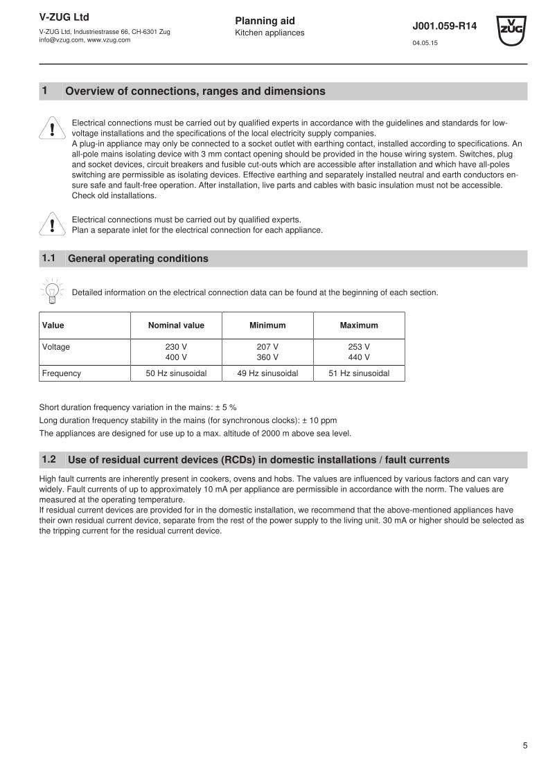
1 Overview of connections, ranges and dimensions
Electrical connections must be carried out by qualified experts in accordance with the guidelines and standards for low-voltage installations and the specifications of the local electricity supply companies.A plug-in appliance may only be connected to a socket outlet with earthing contact, installed according to specifications. Anall-pole mains isolating device with 3 mm contact opening should be provided in the house wiring system. Switches, plugand socket devices, circuit breakers and fusible cut-outs which are accessible after installation and which have all-polesswitching are permissible as isolating devices. Effective earthing and separately installed neutral and earth conductors en-sure safe and fault-free operation. After installation, live parts and cables with basic insulation must not be accessible.Check old installations.
Electrical connections must be carried out by qualified experts.Plan a separate inlet for the electrical connection for each appliance.
1.1 General operating conditions
Detailed information on the electrical connection data can be found at the beginning of each section.
Value Nominal value Minimum Maximum
Voltage 230 V400 V
207 V360 V
253 V440 V
Frequency 50 Hz sinusoidal 49 Hz sinusoidal 51 Hz sinusoidal
Short duration frequency variation in the mains: ± 5 %
Long duration frequency stability in the mains (for synchronous clocks): ± 10 ppm
The appliances are designed for use up to a max. altitude of 2000 m above sea level.
1.2 Use of residual current devices (RCDs) in domestic installations / fault currents
High fault currents are inherently present in cookers, ovens and hobs. The values are influenced by various factors and can varywidely. Fault currents of up to approximately 10 mA per appliance are permissible in accordance with the norm. The values aremeasured at the operating temperature.If residual current devices are provided for in the domestic installation, we recommend that the above-mentioned appliances havetheir own residual current device, separate from the rest of the power supply to the living unit. 30 mA or higher should be selected asthe tripping current for the residual current device.
V-ZUG LtdV-ZUG Ltd, Industriestrasse 66, CH-6301 [email protected], www.vzug.com
Planning aidKitchen appliances
J001.059-R1404.05.15
6
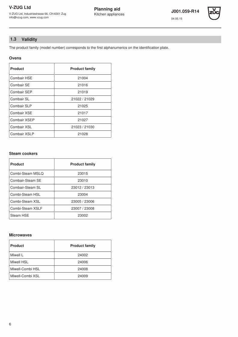
1.3 Validity
The product family (model number) corresponds to the first alphanumerics on the identification plate.
Ovens
Product Product family
Combair HSE 21004
Combair SE 21016
Combair SEP 21019
Combair SL 21022 / 21029
Combair SLP 21025
Combair XSE 21017
Combair XSEP 21027
Combair XSL 21023 / 21030
Combair XSLP 21028
Steam cookers
Product Product family
Combi-Steam MSLQ 23015
Combair-Steam SE 23010
Combair-Steam SL 23012 / 23013
Combi-Steam HSL 23004
Combi-Steam XSL 23005 / 23006
Combi-Steam XSLF 23007 / 23008
Steam HSE 23002
Microwaves
Product Product family
Miwell L 24002
Miwell HSL 24006
Miwell-Combi HSL 24008
Miwell-Combi XSL 24009

V-ZUG LtdV-ZUG Ltd, Industriestrasse 66, CH-6301 [email protected], www.vzug.com
Planning aidKitchen appliances
J001.059-R1404.05.15
7
Coffee-Centers
Product Product family
Supremo HSL 25002
Supremo XSL 25003
Warming & system drawers
Product Product family
SYS6076 35002
SYS60144 35001
WS60144 34010
WS60162 34011
WS60220 34012
WS60283 34013
Glass ceramic hobs – induction
Product Product family
GK16TIWS.1F 31010
GK16TIYS.1F 31008
GK26TIMS 84A
GK26TIMS.1F 31011
GK26TIMS.2F 31001
GK26TIYS.1F 31009
GK37TIMPS, GK37TIMPSC, GK37TIMPSF 31038
GK37TIMS, GK37TIMSC, GK37TIMSF 31041
GK46TIABS, GK46TIABSC 028
GK46TIABS.1F 31017
GK46TIAKS, GK46TIAKSC, GK46TIAKSF 90A
GK46TIMAS, GK46TIMASC, GK46TIMASF 31030
GK46TIMPS, GK46TIMPSC, GK46TIMPSF 31029
GK46TIMS, GK46TIMSC 88A
GK46TIMS.1F 31014
GK46TIMXSC, GK46TIMXSF 31002
GK47TIMPS, GK47TIMPSC, GK47TIMPSF 31036
GK56TIMS, GK56TIMSC 89A
GK56TIMS.1F 31020
V-ZUG LtdV-ZUG Ltd, Industriestrasse 66, CH-6301 [email protected], www.vzug.com
Planning aidKitchen appliances
J001.059-R1404.05.15
8
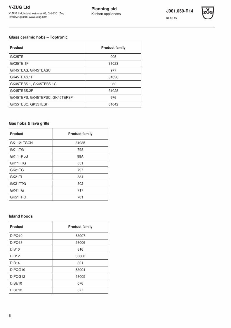
Glass ceramic hobs – Toptronic
Product Product family
GK25TE 005
GK25TE.1F 31023
GK45TEAS, GK45TEASC 977
GK45TEAS.1F 31026
GK45TEBS.1, GK45TEBS.1C 032
GK45TEBS.2F 31028
GK45TEPS, GK45TEPSC, GK45TEPSF 976
GK55TESC, GK55TESF 31042
Gas hobs & lava grills
Product Product family
GK1121TGCN 31035
GK11TG 798
GK11TKLG 98A
GK11TTG 851
GK21TG 797
GK21TI 834
GK21TTG 302
GK41TG 717
GK51TPG 701
Island hoods
Product Product family
DIPQ10 63007
DIPQ13 63006
DIB10 816
DIB12 63008
DIB14 821
DIPQG10 63004
DIPQG12 63005
DISE10 076
DISE12 077
V-ZUG LtdV-ZUG Ltd, Industriestrasse 66, CH-6301 [email protected], www.vzug.com
Planning aidKitchen appliances
J001.059-R1404.05.15
9
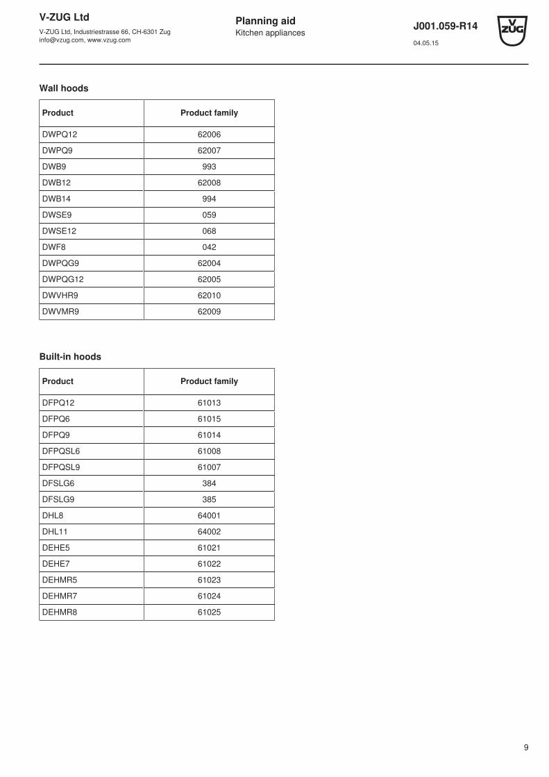
Wall hoods
Product Product family
DWPQ12 62006
DWPQ9 62007
DWB9 993
DWB12 62008
DWB14 994
DWSE9 059
DWSE12 068
DWF8 042
DWPQG9 62004
DWPQG12 62005
DWVHR9 62010
DWVMR9 62009
Built-in hoods
Product Product family
DFPQ12 61013
DFPQ6 61015
DFPQ9 61014
DFPQSL6 61008
DFPQSL9 61007
DFSLG6 384
DFSLG9 385
DHL8 64001
DHL11 64002
DEHE5 61021
DEHE7 61022
DEHMR5 61023
DEHMR7 61024
DEHMR8 61025

V-ZUG LtdV-ZUG Ltd, Industriestrasse 66, CH-6301 [email protected], www.vzug.com
Planning aidKitchen appliances
J001.059-R1404.05.15
10
Ceiling fan
Product Product family
DSDSR12 64003
Refrigerators
Product Product family
Cooltronic 60i 51029
Noblesse 60i 51028
Prestige P 60i eco 51052
Prestige 60i eco 51045
Prestige 60i 51027
Magnum 60i eco 51031
Futura 60i eco 51061
Futura 60i 51020
Royal 60i 51018
De Luxe 60i eco 51060
De Luxe 60i 51064
Komfort 60i 51048
Winecooler SL 629
Dishwashers
Product Product family
GS Adora N 41011, 41029, 41030, 41032
GS Adora S 41016, 41034, 41036
GS Adora SL 41005-41008, 41042, 41043
GS Adora SL WP 41009, 41038

V-ZUG LtdV-ZUG Ltd, Industriestrasse 66, CH-6301 [email protected], www.vzug.com
Planning aidKitchen appliances
J001.059-R1404.05.15
11
1.4 Positions of electrical connections
For EURO kitchens, allowance from the floor can vary. in this case, the electrical connection should be calculated using the dimen-sion from the bottom edge of the appliance.
Oven above an ovenWith this combination, an electrical connection should be provided for each appliance. Depending on the installation height and thetype of combination, the connections may be located at different heights.
Wall hoods with telescopic casingThe electrical connection must pass between the exhaust air piping and the lagging sheets. The measurements given in the table en-sure that this condition is met.
M3
7
M1
M2
6
1
3
4
5
2
8
1 Wide switch box / control box / autarchic hob2 Refrigerator in base unit / dishwasher3 Oven/coffee-center4 Combinations (oven / steam cooker / microwave)5 Refrigerator in tall unit6 Microwave in a wall unit7 Range hood8 Warming drawer
M1 Distance from centre to dishwasher/refrigerator connection in base unitM2 Distance from centre to coffee-center connectionM3 Distance from centre to range hood connection
Provide additional clearance for electrical connections if the niche has only the minimum depth.
V-ZUG LtdV-ZUG Ltd, Industriestrasse 66, CH-6301 [email protected], www.vzug.com
Planning aidKitchen appliances
J001.059-R1404.05.15
12
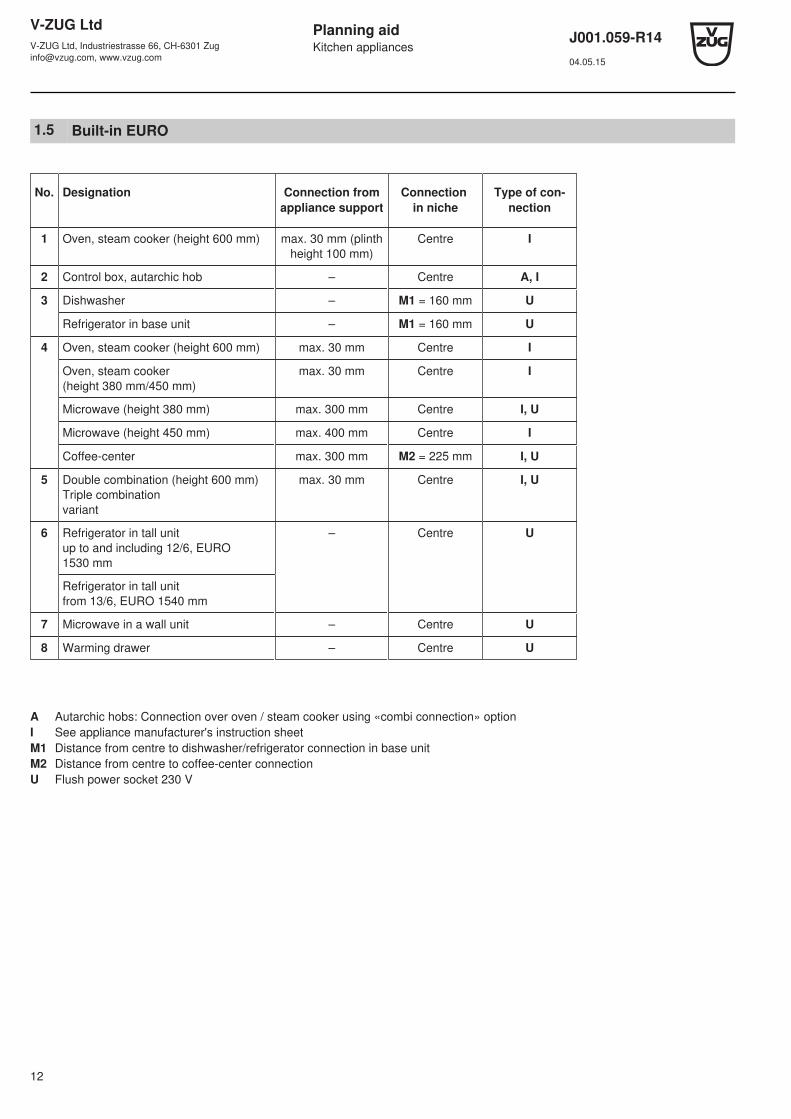
1.5 Built-in EURO
No. Designation Connection fromappliance support
Connection in niche
Type of con-nection
1 Oven, steam cooker (height 600 mm) max. 30 mm (plinthheight 100 mm)
Centre I
2 Control box, autarchic hob – Centre A, I
3 Dishwasher – M1 = 160 mm U
Refrigerator in base unit – M1 = 160 mm U
4 Oven, steam cooker (height 600 mm) max. 30 mm Centre I
Oven, steam cooker(height 380 mm/450 mm)
max. 30 mm Centre I
Microwave (height 380 mm) max. 300 mm Centre I, U
Microwave (height 450 mm) max. 400 mm Centre I
Coffee-center max. 300 mm M2 = 225 mm I, U
5 Double combination (height 600 mm)Triple combinationvariant
max. 30 mm Centre I, U
6 Refrigerator in tall unitup to and including 12/6, EURO1530 mm
– Centre U
Refrigerator in tall unitfrom 13/6, EURO 1540 mm
7 Microwave in a wall unit – Centre U
8 Warming drawer – Centre U
A Autarchic hobs: Connection over oven / steam cooker using «combi connection» optionI See appliance manufacturer's instruction sheetM1 Distance from centre to dishwasher/refrigerator connection in base unitM2 Distance from centre to coffee-center connectionU Flush power socket 230 V
V-ZUG LtdV-ZUG Ltd, Industriestrasse 66, CH-6301 [email protected], www.vzug.com
Planning aidKitchen appliances
J001.059-R1404.05.15
13
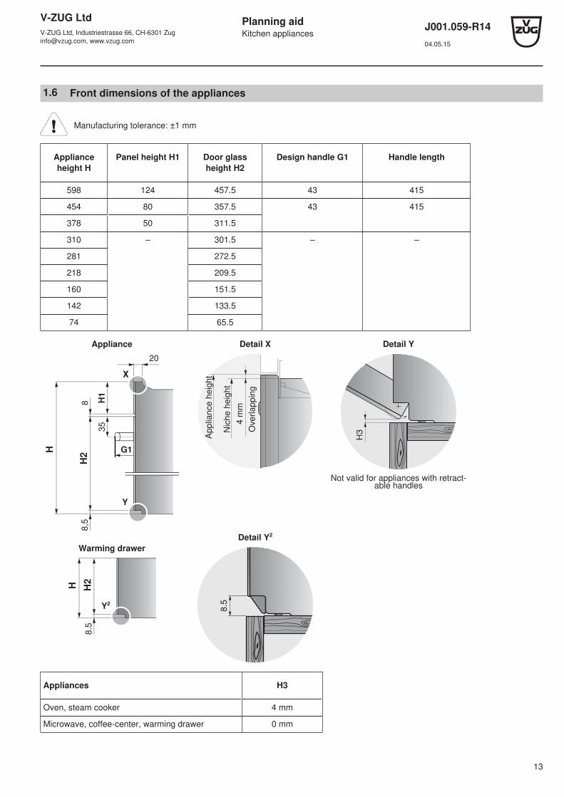
1.6 Front dimensions of the appliances
Manufacturing tolerance: ±1 mm
Applianceheight H
Panel height H1 Door glassheight H2
Design handle G1 Handle length
598 124 457.5 43 415
454 80 357.5 43 415
378 50 311.5
310 – 301.5 – –
281 272.5
218 209.5
160 151.5
142 133.5
74 65.5
Appliance
X
8,5
Y
8
35
20
H1
G1
H2
H
Detail X
4 m
m
Ove
rlappin
g
Applia
nce h
eig
ht
Nic
he h
eig
ht
Detail Y
H3
Not valid for appliances with retract-able handles
Warming drawer
8.5
Y²
H2
H
Detail Y²
8.5
Appliances H3
Oven, steam cooker 4 mm
Microwave, coffee-center, warming drawer 0 mm
V-ZUG LtdV-ZUG Ltd, Industriestrasse 66, CH-6301 [email protected], www.vzug.com
Planning aidKitchen appliances
J001.059-R1404.05.15
14
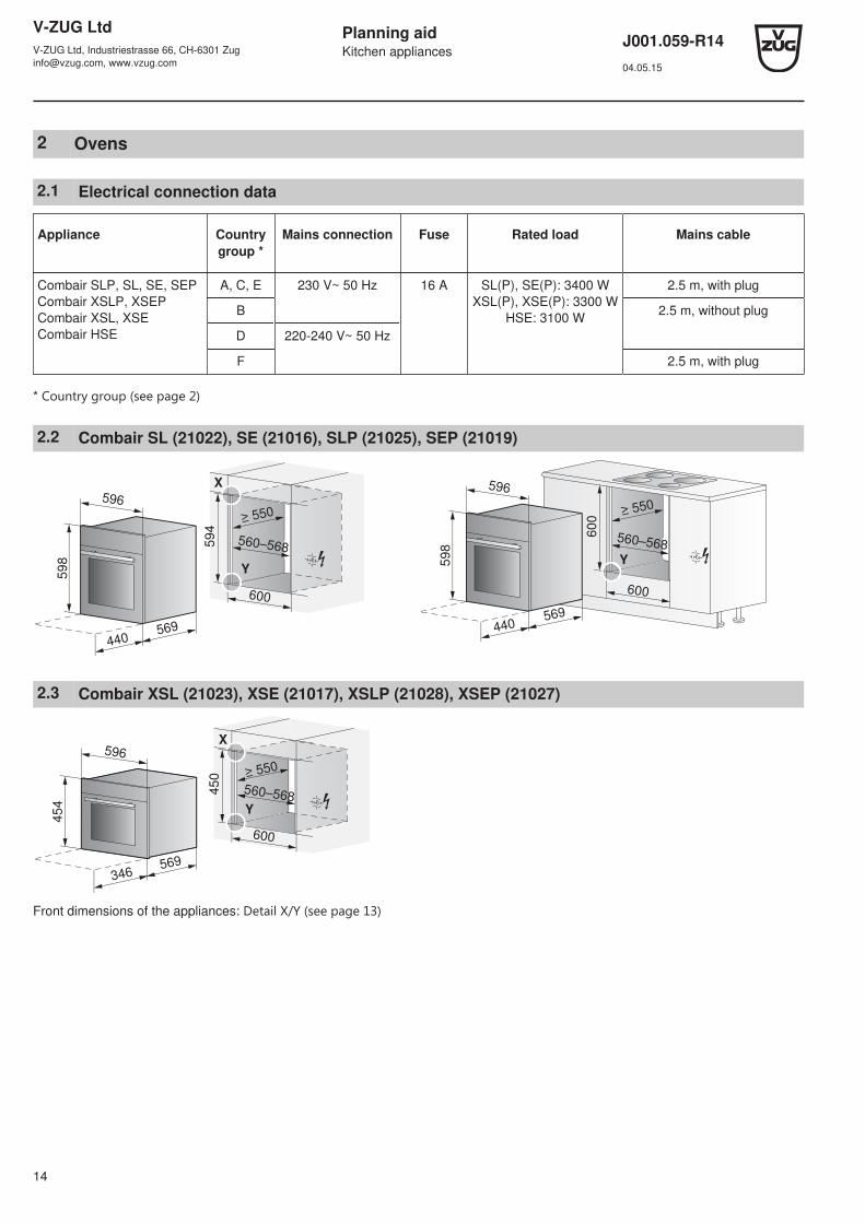
2 Ovens
2.1 Electrical connection data
Appliance Countrygroup *
Mains connection Fuse Rated load Mains cable
Combair SLP, SL, SE, SEPCombair XSLP, XSEPCombair XSL, XSECombair HSE
A, C, E 230 V~ 50 Hz 16 A SL(P), SE(P): 3400 WXSL(P), XSE(P): 3300 W
HSE: 3100 W
2.5 m, with plug
B 2.5 m, without plug
D 220-240 V~ 50 Hz
F 2.5 m, with plug
* Country group ﴾see page 2﴿
2.2 Combair SL (21022), SE (21016), SLP (21025), SEP (21019)
598
569
440
596
600
≥ 550
560–568594
X
Y
440569
600
600
598
596
560–568
Y
2.3 Combair XSL (21023), XSE (21017), XSLP (21028), XSEP (21027)
454
596
569
600
≥ 550
450
560–568
X
346
Y
Front dimensions of the appliances: Detail X/Y ﴾see page 13﴿
V-ZUG LtdV-ZUG Ltd, Industriestrasse 66, CH-6301 [email protected], www.vzug.com
Planning aidKitchen appliances
J001.059-R1404.05.15
15
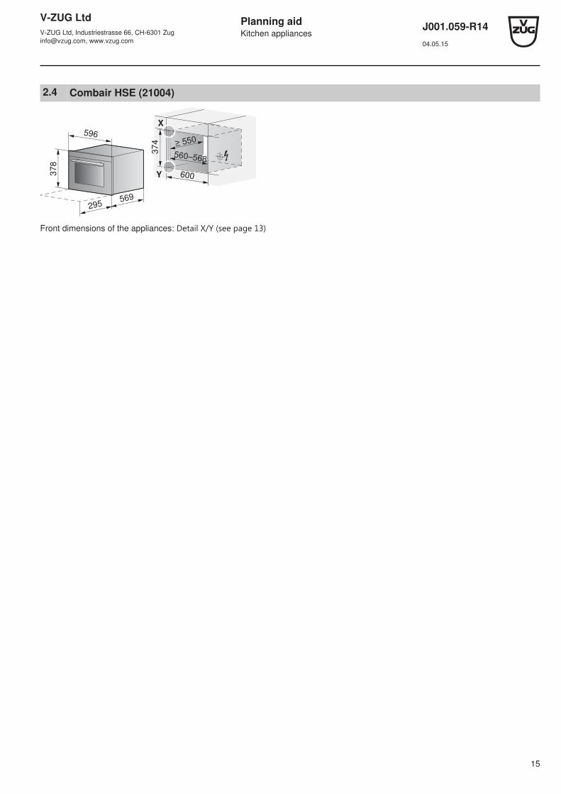
2.4 Combair HSE (21004)
378
596
569
295
600
≥ 550
374
560–568
X
Y
Front dimensions of the appliances: Detail X/Y ﴾see page 13﴿

V-ZUG LtdV-ZUG Ltd, Industriestrasse 66, CH-6301 [email protected], www.vzug.com
Planning aidKitchen appliances
J001.059-R1404.05.15
16
3 Steam cookers
Only use if water hardness > 3 French degrees (> 1.7 German degrees) possible.
3.1 Electrical connection data
Appliance Country group * Mains connection Fuse Rated load Mains cable
Combi-SteamMSLQ **
A, B, C, D, E, F 400 V 2N~ 50 Hz 16 A 5700 W 2.5 m, without plug
230 V~ 50 Hz 25 A
Combair-SteamSL, SECombi-SteamHSL, XSLF, XSLF
A, C, E 230 V~ 50 Hz 16 A S, N, XSL(F): 3700 WSL: 3500 W
2.1 m, with plug
B 2.1 m, without plug
D 220-240 V~ 50 Hz
F 2.1 m, with plug
Steam HSE A, B, C, E 230 V~ 50 Hz 10 A 2200 W 2.1 m, with plug
D, F 220-240 V~ 50 Hz
* Country group ﴾see page 2﴿ ** The Combi-Steam MSLQ can also be operated with a single-phase connection (230 V~ / max. 16 A). For performance reasons,however, it is to be connected with a two-phase connection or fitted with a 25 amp fuse whenever possible.
3.2 Air circulation diagram for Combi-Steam MSLQ
For proper ventilation, prepare appliance niche with an air intake, positions A and B, of at least 80 to ≤ 850 cm2 in total,where B has to account for at least 60 cm2.
Installation below an Induktionskochfeld ﴾see page 48﴿.
A
B
Air intake
Air exhaust

V-ZUG LtdV-ZUG Ltd, Industriestrasse 66, CH-6301 [email protected], www.vzug.com
Planning aidKitchen appliances
J001.059-R1404.05.15
17
3.3 Combi-Steam MSLQ (23015)
598
569
440
596
600
≥ 550
560–568594
X
589
Y
3.4 Combair-Steam SL (23012), SE (23010)
598
569
440
596
600
≥ 550
560–568594
X
Y
440569
600
600
598
596
560–568
Y
3.5 Combi-Steam HSL (23004), Steam HSE (23002)
378
596
569
295
600
≥ 550
374
560–568
X
Y
3.6 Combi-Steam XSL (23005)
454
596
569
600
≥ 550
450
560–568
X
346
Y
Front dimensions of the appliances: Detail X/Y ﴾see page 13﴿

V-ZUG LtdV-ZUG Ltd, Industriestrasse 66, CH-6301 [email protected], www.vzug.com
Planning aidKitchen appliances
J001.059-R1404.05.15
18
3.7 Combi-Steam XSLF (23007)
454
596
569
600
575450
560–568
X
346
≥ 60Y
Front dimensions of the appliances: Detail X/Y ﴾see page 13﴿
Below second applianceDepth > 555 mm
Above second applianceDepth > 575 mm
Above warming drawerDepth > 555 mm
W
X4
56
Y
50
≥ 60
W
450
X
Y
50
≥ 60
W450
X
Y
50
≥ 60
X = Height of second applianceY = Niche heightW = Angle set K20198
For an installation depth under 575 mm, it is recommended that the appliance be installed below other appliances for spacereasons.If installing with a second appliance in the same niche, use the angle set 60 W (K20198).
V-ZUG LtdV-ZUG Ltd, Industriestrasse 66, CH-6301 [email protected], www.vzug.com
Planning aidKitchen appliances
J001.059-R1404.05.15
19
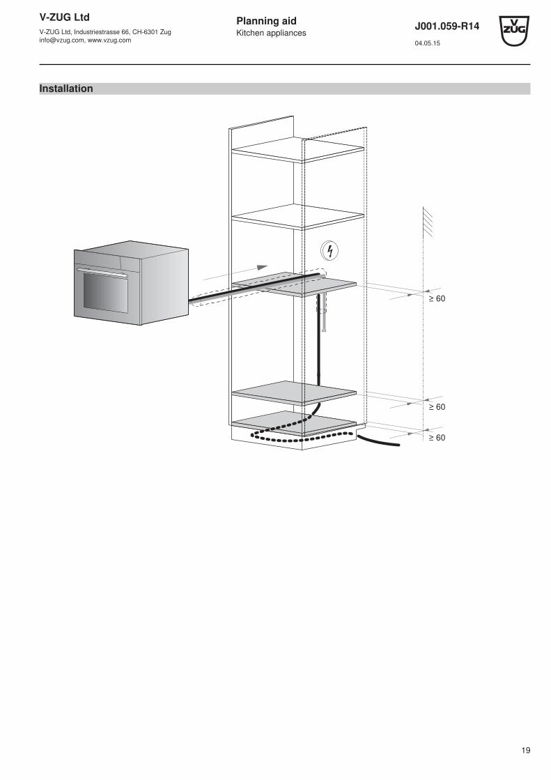
Installation
≥ 60
≥ 60
≥ 60
V-ZUG LtdV-ZUG Ltd, Industriestrasse 66, CH-6301 [email protected], www.vzug.com
Planning aidKitchen appliances
J001.059-R1404.05.15
20
Plumbing in
1
4
2 73 56
≥ 5
0
70
0
1
2
3
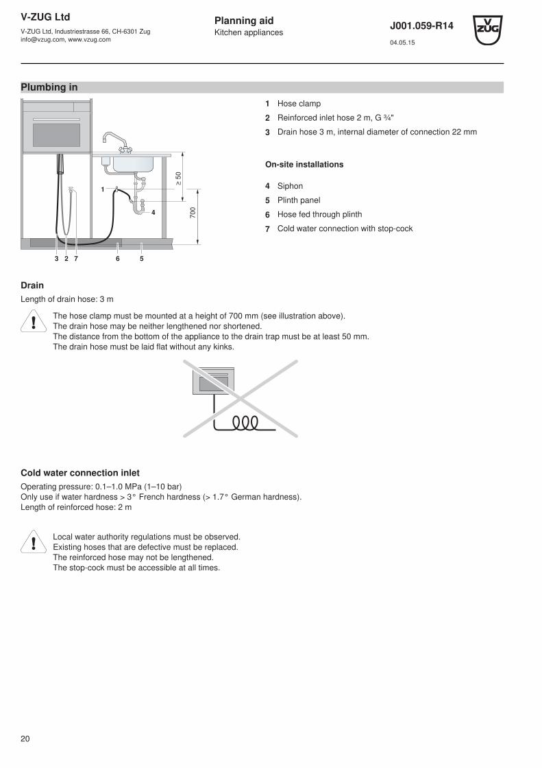
Hose clamp
Reinforced inlet hose 2 m, G ¾"
Drain hose 3 m, internal diameter of connection 22 mm
On-site installations
4
5
6
7
Siphon
Plinth panel
Hose fed through plinth
Cold water connection with stop-cock
DrainLength of drain hose: 3 m
The hose clamp must be mounted at a height of 700 mm (see illustration above).The drain hose may be neither lengthened nor shortened.The distance from the bottom of the appliance to the drain trap must be at least 50 mm.The drain hose must be laid flat without any kinks.
Cold water connection inletOperating pressure: 0.1–1.0 MPa (1–10 bar)Only use if water hardness > 3° French hardness (> 1.7° German hardness).Length of reinforced hose: 2 m
Local water authority regulations must be observed.Existing hoses that are defective must be replaced.The reinforced hose may not be lengthened.The stop-cock must be accessible at all times.
V-ZUG LtdV-ZUG Ltd, Industriestrasse 66, CH-6301 [email protected], www.vzug.com
Planning aidKitchen appliances
J001.059-R1404.05.15
21
4 Microwaves
Minimum installation height (child safety): Keep 850 mm distance from the floor to the bottom edge of the microwave!
The mounting angles are not included in the scope of delivery. Order angle set K50572 at the same time.
4.1 Electrical connection data
Appliance Mains connection Fuse Connection cable Mains cable
Miwell-Combi XSL 230 V~ 50 Hz 16 A 2800 W 1.2 m, without plug
Miwell-Combi HSL 10 A 2300 W 1.2 m, with plug
Miwell HSL / L 1300 W
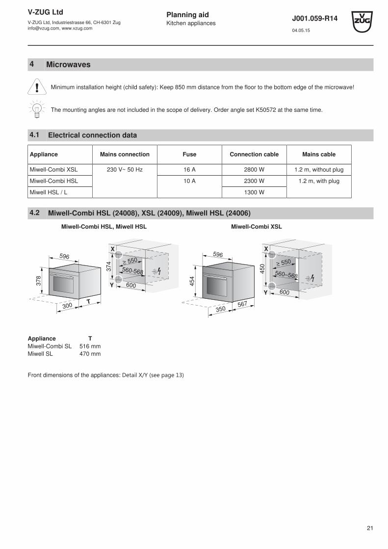
4.2 Miwell-Combi HSL (24008), XSL (24009), Miwell HSL (24006)
Miwell-Combi HSL, Miwell HSL Miwell-Combi XSL
378
596
T300
600
≥ 550
374
560-568
X
Y 454
596
567
600
450
560–568
X
350
Y
Appliance TMiwell-Combi SL 516 mmMiwell SL 470 mm
Front dimensions of the appliances: Detail X/Y ﴾see page 13﴿

V-ZUG LtdV-ZUG Ltd, Industriestrasse 66, CH-6301 [email protected], www.vzug.com
Planning aidKitchen appliances
J001.059-R1404.05.15
22
4.3 Miwell L (24002)
Left-hand opening!
2050
==
600381
762
596
378
320
≥ 330
560
Y

V-ZUG LtdV-ZUG Ltd, Industriestrasse 66, CH-6301 [email protected], www.vzug.com
Planning aidKitchen appliances
J001.059-R1404.05.15
23
5 Coffee-Centers
Depth of wall unit must be at least 480 mm.
5.1 Electrical connection data
Mains connection Fuse Rated load Mains cable
230 V~ 50Hz 10 A 1350 W 1.8 m, with plug
5.2 Supremo HSL (25002)
600
550
560–568
X
596 412
37
8
480
Y
37
4
5.3 Supremo XSL (25003)
600
450
550
560-568
596 412
454
X
480
Y
Front dimensions of the appliances: Detail X/Y ﴾see page 13﴿
V-ZUG LtdV-ZUG Ltd, Industriestrasse 66, CH-6301 [email protected], www.vzug.com
Planning aidKitchen appliances
J001.059-R1404.05.15
24
6 Warming and system drawers
6.1 General notes
Efficient repairs can only be guaranteed if it is possible to uninstall the whole appliance at any time without causing anydamage.
6.2 Electrical connection data
Plan a separate inlet for the electrical connection for each appliance.
General information on the electrical connections and an overview of the positions can be found in section Overview of con-nections, ranges and dimensions ﴾see page 5﴿.
Mains connection Fuse Rated load Mains cable
230 V~ 50 Hz 10 A 810 W 1.7 m, with plug
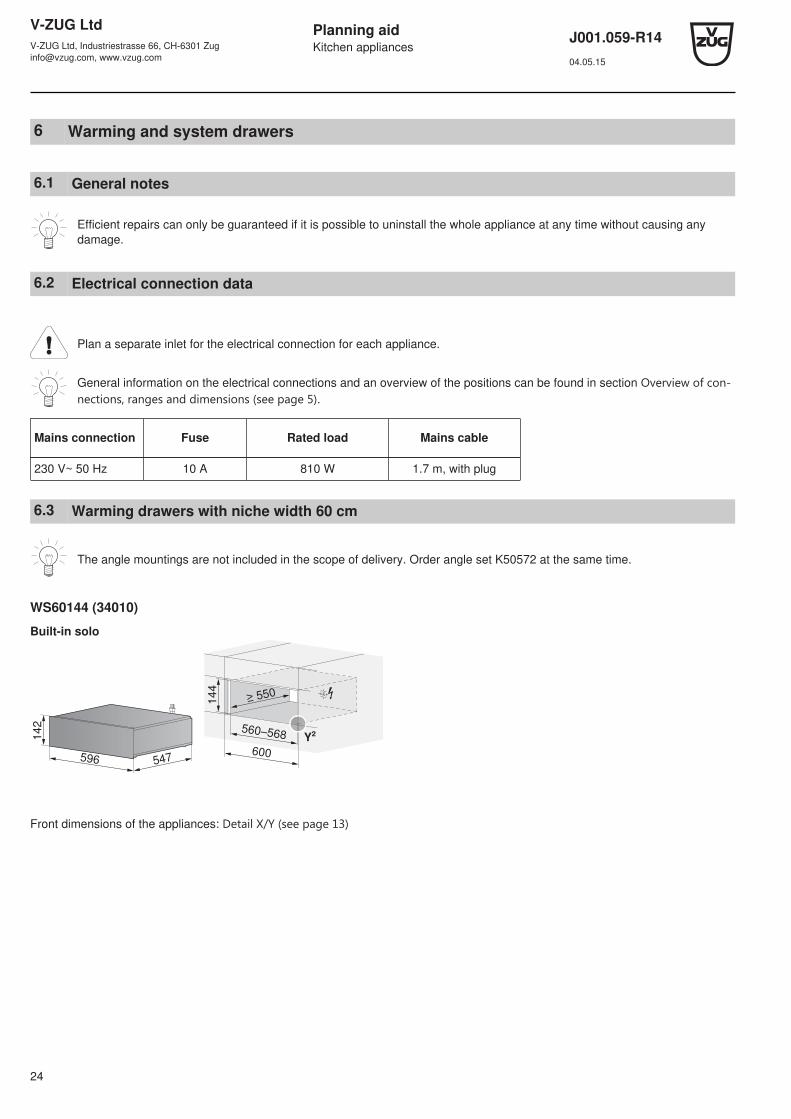
6.3 Warming drawers with niche width 60 cm
The angle mountings are not included in the scope of delivery. Order angle set K50572 at the same time.
WS60144 (34010)
Built-in solo
144
560–568
596 547
142
600
≥ 550
Y²
Front dimensions of the appliances: Detail X/Y ﴾see page 13﴿
V-ZUG LtdV-ZUG Ltd, Industriestrasse 66, CH-6301 [email protected], www.vzug.com
Planning aidKitchen appliances
J001.059-R1404.05.15
25
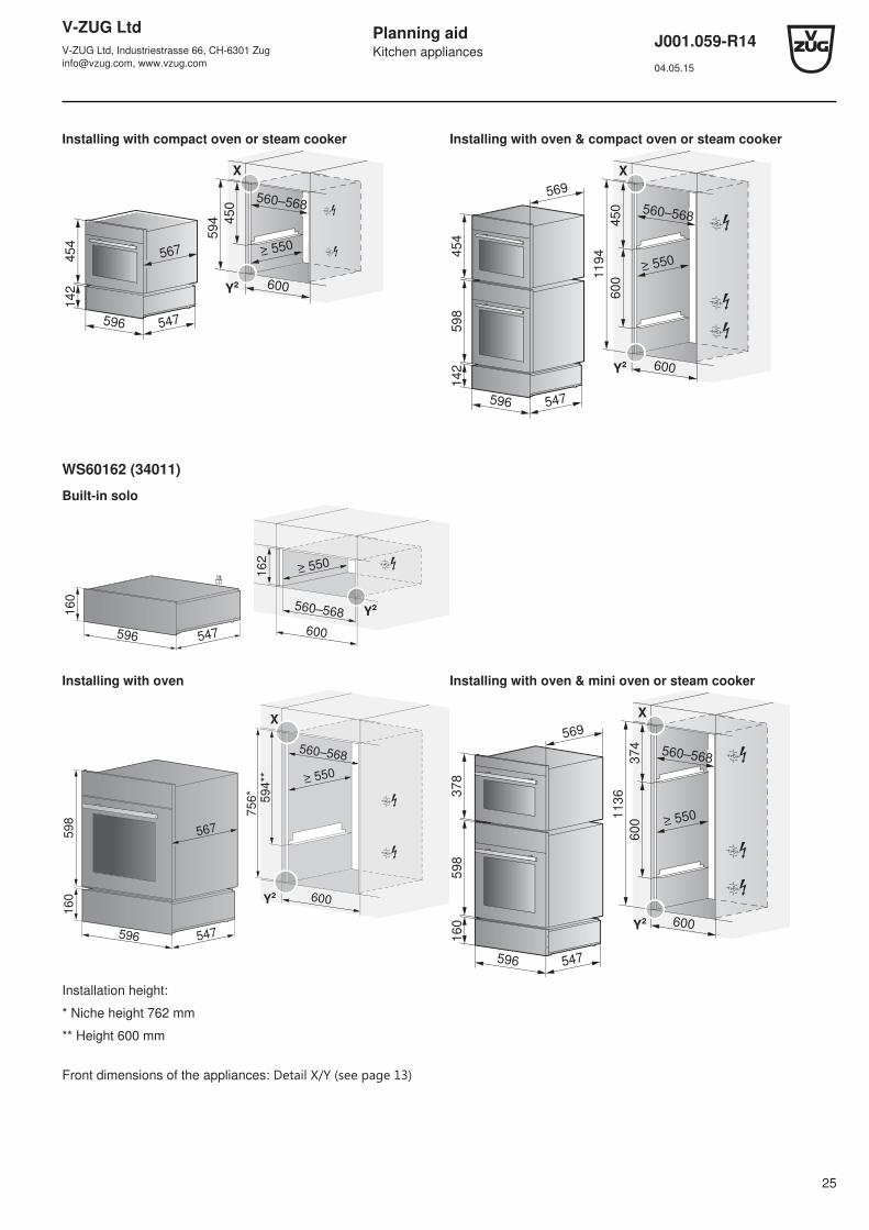
Installing with compact oven or steam cooker Installing with oven & compact oven or steam cooker
45
4 1
42
596 547
567
600
560–5685
94 4
50
X
≥ 550
Y²
≥ 550
600
560–568
59
8 1
42
596 547
569
45
4
1194
450
X
600
Y²
WS60162 (34011)
Built-in solo
162
560–568
596 547
160
600
≥ 550
Y²
Installing with oven Installing with oven & mini oven or steam cooker
598
160
596 547
600
560–568
756*
594**
X
567
≥ 550
Y²
596 547
598
160
378
569
≥ 550
600
560–568
1136
374
X
600
Y²
Installation height:
* Niche height 762 mm
** Height 600 mm
Front dimensions of the appliances: Detail X/Y ﴾see page 13﴿

V-ZUG LtdV-ZUG Ltd, Industriestrasse 66, CH-6301 [email protected], www.vzug.com
Planning aidKitchen appliances
J001.059-R1404.05.15
26
WS60220 (34012)
Built-in solo Installing with mini oven or steam cooker
220
560–568
596 547
218
600
≥ 550
Y²
378
218
596 547
600
560–568
594
374
X
567
≥ 550
Y²
For niche height 635 mm -> Adapter frame see section Zubehör ﴾see page 119﴿
WS60283 (34013)
Built-in solo Installing with oven
283
560–568
596 547
281
600
≥ 550
Y²
598
281
596 547
600
560–568
877
594
X
567
≥ 550
Y²
Front dimensions of the appliances: Detail X/Y ﴾see page 13﴿

V-ZUG LtdV-ZUG Ltd, Industriestrasse 66, CH-6301 [email protected], www.vzug.com
Planning aidKitchen appliances
J001.059-R1404.05.15
27
6.4 System drawers with niche width 60 cm
SYS60144 (35001)
Installing with Supremo XSL
≥ 550
600
560–568
594
450
X
142
596 547
398
454 480
Y²
SYS6076 (35002)
Installing with Supremo HSL
600
≥ 550
560–568
450
374
X
Y²
74
596 560
412
378
The telescopic runner for the assembly and operation is included in the scope of delivery.
Front dimensions of the appliances: Detail X/Y ﴾see page 13﴿
V-ZUG LtdV-ZUG Ltd, Industriestrasse 66, CH-6301 [email protected], www.vzug.com
Planning aidKitchen appliances
J001.059-R1404.05.15
28
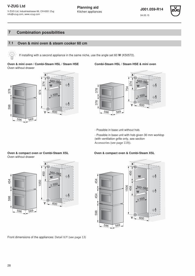
7 Combination possibilities
7.1 Oven & mini oven & steam cooker 60 cm
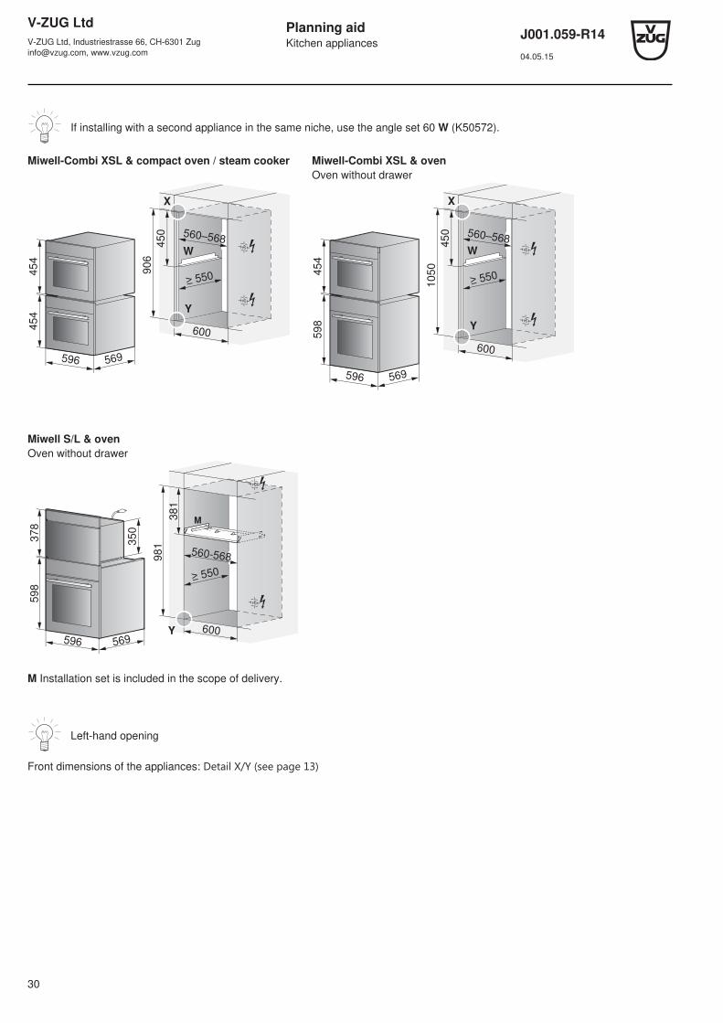
If installing with a second appliance in the same niche, use the angle set 60 W (K50572).
Oven & mini oven / Combi-Steam HSL / Steam HSEOven without drawer
Combi-Steam HSL / Steam HSE & mini oven
≥ 550
600
560–568
596 569
598
378
974
374
X
Y
W
≥ 550
600
560–568
596 569
37
83
78
75
4
37
4
X
Y
W
- Possible in base unit without hob.
- Possible in base unit with hob given 30 mm worktop(with ventilation grille only, see section Accessories ﴾see page 119﴿).
Oven & compact oven or Combi-Steam XSLOven without drawer
Oven & compact oven & Combi-Steam XSL
≥ 550
600
560–568
596 569
59
84
54
10
50
45
0
X
W
Y
X
45
4
≥ 550
600
560–568
596 569
59
84
54
15
06
45
64
50
W
W
Y
Front dimensions of the appliances: Detail X/Y ﴾see page 13﴿
V-ZUG LtdV-ZUG Ltd, Industriestrasse 66, CH-6301 [email protected], www.vzug.com
Planning aidKitchen appliances
J001.059-R1404.05.15
29
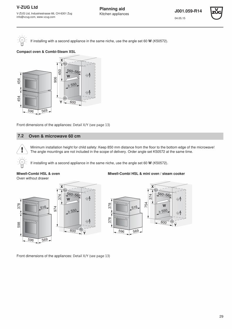
If installing with a second appliance in the same niche, use the angle set 60 W (K50572).
Compact oven & Combi-Steam XSL
≥ 550
600
560–568
596 569
45
44
54
90
6
45
0X
W
Y
Front dimensions of the appliances: Detail X/Y ﴾see page 13﴿
7.2 Oven & microwave 60 cm
Minimum installation height for child safety: Keep 850 mm distance from the floor to the bottom edge of the microwave!The angle mountings are not included in the scope of delivery. Order angle set K50572 at the same time.
If installing with a second appliance in the same niche, use the angle set 60 W (K50572).
Miwell-Combi HSL & oven Miwell-Combi HSL & mini oven / steam cookerOven without drawer
596 569
516
≥ 550
600
560–568
59
83
78
97
4
37
4
X
Y
W
596 569
516
≥ 550
600
560–568
378
378
754
374
X
Y
W
Front dimensions of the appliances: Detail X/Y ﴾see page 13﴿
V-ZUG LtdV-ZUG Ltd, Industriestrasse 66, CH-6301 [email protected], www.vzug.com
Planning aidKitchen appliances
J001.059-R1404.05.15
30
If installing with a second appliance in the same niche, use the angle set 60 W (K50572).
Miwell-Combi XSL & compact oven / steam cooker Miwell-Combi XSL & ovenOven without drawer
600
560–568
596 569
454
454
906
450
X
Y
W
600
560–568
596 569
59
84
54
10
50
45
0
X
Y
W
Miwell S/L & ovenOven without drawer
M
596 569
≥ 550
560-568
598
378
981
381
350
600Y
M Installation set is included in the scope of delivery.
Left-hand opening
Front dimensions of the appliances: Detail X/Y ﴾see page 13﴿
V-ZUG LtdV-ZUG Ltd, Industriestrasse 66, CH-6301 [email protected], www.vzug.com
Planning aidKitchen appliances
J001.059-R1404.05.15
31
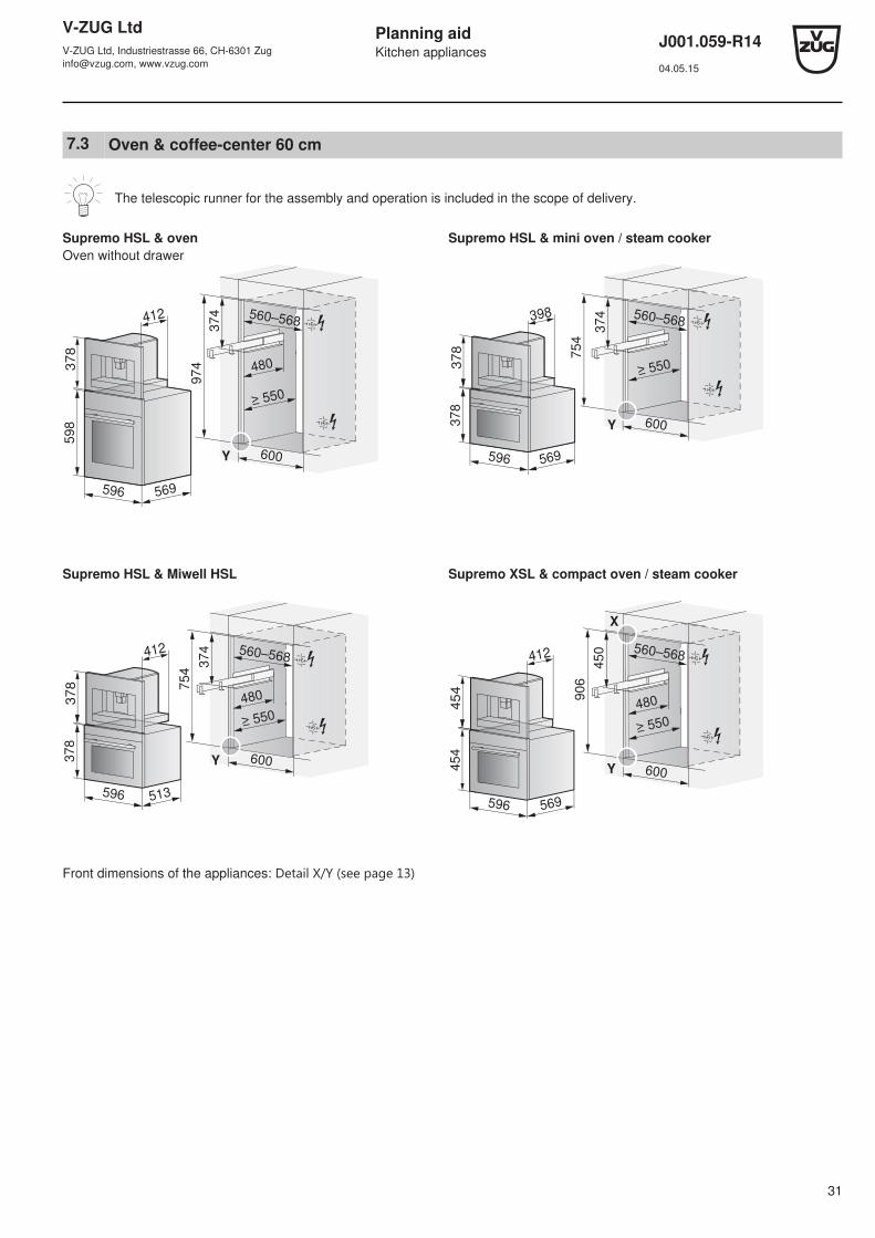
7.3 Oven & coffee-center 60 cm
The telescopic runner for the assembly and operation is included in the scope of delivery.
Supremo HSL & oven Supremo HSL & mini oven / steam cookerOven without drawer
596 569
≥ 550
600
560–568
598
974
374
412
378
480
Y 596 569
≥ 550
600
560–568
378
754
374398
378
Y
Supremo HSL & Miwell HSL Supremo XSL & compact oven / steam cooker
596 513
378
≥ 550
600
560–568
754
374412
378
480
Y
596 569
≥ 550
600
560–568
906
450
X
454
412
454
480
Y
Front dimensions of the appliances: Detail X/Y ﴾see page 13﴿
V-ZUG LtdV-ZUG Ltd, Industriestrasse 66, CH-6301 [email protected], www.vzug.com
Planning aidKitchen appliances
J001.059-R1404.05.15
32
8 Glass ceramic hobs – induction, wok, teppanyaki
8.1 General notes
It is imperative for induction hobs to have adequate ventilation (see sections Installation without protective plate ﴾see page 44﴿ and Installation with protective plate ﴾see page 46﴿).This is guaranteed with a worktop depth of 20 mm to 40 mm
If a drawer is installed directly underneath, a protective plate is recommended in the vicinity of the mains cable and to pro-tect the ventilation openings. The protective plate set can be used (see Accessories ﴾see page 119﴿).
With a front-facing air gap of 3 mm, a ventilation protective plate with seal is essential (Installation with protective plate ﴾seepage 46﴿).
Efficient repairs can only be guaranteed if it is possible to uninstall the whole appliance at any time without causing anydamage.
The layout of the hobs to be installed may differ from the hobs illustrated here!
Dear Customer
This planning aid contains the dimensions of all our current glass ceramic hobs.Since April 2013, most of the flush induction hobs require larger cut-out dimensions and other corner radii. If you own an appliancewhich was manufactured before April 2013, please make sure that you do select the correct cut-out dimensions.The cut-out dimensions for flush induction hobs can be found in section Glass ceramic hobs for the replacement market ﴾see page58﴿.Some replacement appliances with the previous dimensions are still available upon request.
Thank you for reading this information.
Your V-ZUG Ltd

V-ZUG LtdV-ZUG Ltd, Industriestrasse 66, CH-6301 [email protected], www.vzug.com
Planning aidKitchen appliances
J001.059-R1404.05.15
33
8.2 Electrical connection data
Appliance Country group * Mains connection Fuse Rated load Mains cable
GK16TIWS.1F A, B, C, D, E, F 220-240 V~50/60 Hz 16 A 3000 W 1.7 m, without plug
GK16TIYS.1F 2800 W
GK26TIMS … 3700 W
GK26TIYS.1F A, E 380-415 V 2N~ 50/60 Hz 5600 W
B, C, D, F 220-240 V~50/60 Hz 32 A 5600 W
GK37TIM…,GK46TI…,GK47TIM…
A, E 380-415 V 2N~ 50/60 Hz 16 A 7400 W
B, C, D, F 220-240 V~50/60 Hz 32 A
GK56TIMS … A, E 380-415 V 3N~ 50/60 Hz 16 A 11100 W
B, C, D, F 220-240 V~50/60 Hz 48 A
* Country group ﴾see page 2﴿
8.3 Ventilation
To ensure good ventilation, there must be≥ 17.5 mm of space under the appliance.
1. The rear panel of the floor unit must be openaround the work surface cut-out in order toguarantee continuous air circulation via theventilation slits.The air must be drawn in from outside thecabinet and be able to circulate freely frominside the cabinet to the hob.
2. Alternatively, a concealed fresh air supplycan ensure air circulation inside the cabinet.So that enough cool air can be drawn in,there must be a continuous supply of freshair circulating till outside the cabinet.The air must be drawn in from outside thecabinet and be able to circulate freely frominside the cabinet to the hob.
≥ 15
21

V-ZUG LtdV-ZUG Ltd, Industriestrasse 66, CH-6301 [email protected], www.vzug.com
Planning aidKitchen appliances
J001.059-R1404.05.15
34
8.4 Framed installation
Aim for corner radii of cut-out: ≤ 10 mm.Corner radii of appliance: 8 mm
GK26TIMS (84A) GK37TIMS (31041), GK37TIMSC (31041), GK46TIMS (88A), GK46TIMSC (88A)
514
289
H
Y
Y
≥ 5
0
≥ 5
0
490
±1
600
265 ±1
A
275
Ri
Ra
490
±1
560 ±1
600
≥ 5
0
≥ 5
0
A
600
584
514
Y
Y
Ri
H
Ra
≥ 1
7.5
*
B
Y – Y
Drawer/Cabinet
* The required clearance must be observed!
Appliance ADepends on producer
B H Corner radiusRa/Ri
GK26TIMS ≥ 30 mm ≥ 65.2 mm 47.7 mm 10/8 mm
GK37TIMS, GK46TIMS
GK37TIMSC,GK46TIMSC
≥67.2 mm 49.7 mm
A Worktop depth (only applies in combination with directly built-under oven / steam cooker with type of construction60-600, without Combi-Steam MSLQ)
B Required clearance for ventilationH Measurement from the top side of the worktop to the underside of the hob (ventilation opening)Ri Corner radii of applianceRa Outer corner radii of cut-out
V-ZUG LtdV-ZUG Ltd, Industriestrasse 66, CH-6301 [email protected], www.vzug.com
Planning aidKitchen appliances
J001.059-R1404.05.15
35
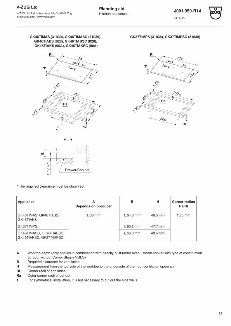
GK46TIMAS (31030), GK46TIMASC (31030), GK46TIABS (028), GK46TIABSC (028), GK46TIAKS (90A), GK46TIAKSC (90A)
GK37TIMPS (31038), GK37TIMPSC (31038)
514
H
774
Y
Y
490
±1
≥ 5
0
≥ 5
0
600
750 ±1
600
A
1
Ri
Ra
H
774
444
Y
Y
420
±1
≥ 5
0
≥ 5
0
750 ±1
600
A
Ri
Ra
≥ 1
7.5
*
B
Y – Y
Drawer/Cabinet
* The required clearance must be observed!
Appliance ADepends on producer
B H Corner radiusRa/Ri
GK46TIMAS, GK46TIABS,GK46TIAKS
≥ 30 mm ≥ 64.0 mm 46.5 mm 10/8 mm
GK37TIMPS ≥ 65.2 mm 47.7 mm
GK46TIMASC, GK46TIABSC,GK46TIAKSC, GK37TIMPSC
≥ 66.0 mm 48.5 mm
A Worktop depth (only applies in combination with directly built-under oven / steam cooker with type of construction60-600, without Combi-Steam MSLQ)
B Required clearance for ventilationH Measurement from the top side of the worktop to the underside of the hob (ventilation opening)Ri Corner radii of applianceRa Outer corner radii of cut-out1 For symmetrical installation, it is not necessary to cut out the side walls

V-ZUG LtdV-ZUG Ltd, Industriestrasse 66, CH-6301 [email protected], www.vzug.com
Planning aidKitchen appliances
J001.059-R1404.05.15
36
GK46TIMXSC (31002) GK46TIMPS (31029), GK46TIMPSC (31029), GK47TIMPS (31036), GK47TIMPSC (31036)
514
H
704
Y
Y
Ri
490
±1
≥ 5
0
≥ 5
0
A
600
680 ±1
600
=
=
=
=
2
Ra
410
910
H
Y
Y
X
X
1
123
A
886 ±1
386
±1
900
≥ 7
0
≥ 7
0
200
50
825
=
=
386
Ri
Ra
≥ 1
7.5
*
B
Y – Y
Drawer/Cabinet
X – X
≥
15
≥ 1
7.5
*
B
Drawer/
cabinet/
side panel
* The required clearance must be observed!
For niche width 900/825 mm, cut-outs in side walls left/right are necessary for the ventilation of the appliance. Keep blow-out opening free.
Appliance A Depends on producer B H Corner radius Ra/Ri
GK46TIMPS ≥ 30 mm ≥ 64.5 mm 47.0 mm 10/8 mm
GK47TIMPS ≥ 62.8 mm 45.3 mm
GK46TIMPSC ≥ 67.2 mm 49.7 mm
GK47TIMPSC ≥ 65.5 mm 48.0 mm
GK46TIMXSC ≥ 66.0 mm 48.5 mm
A Worktop depth (only applies in combination with directly built-under oven / steam cooker with type of construction60-600, without Combi-Steam MSLQ)
B Required clearance for ventilationH Measurement from the top side of the worktop to the underside of the hob (ventilation opening)Ri Corner radii of applianceRa Outer corner radii of cut-out1 Front and rear struts are reinforced on the underside. The strut width is determined by the producer of the stone
worktop. The minimum strut width can vary according to the property of the stone.2 For symmetrical installation, it is not necessary to cut out the side walls

V-ZUG LtdV-ZUG Ltd, Industriestrasse 66, CH-6301 [email protected], www.vzug.com
Planning aidKitchen appliances
J001.059-R1404.05.15
37
GK56TIMS (89A), GK56TIMSC (89A)
514
910
H
900
A
600
886 ±1
≥ 5
0
490 ±
1
≥ 5
0
Y
Y
B
825
=
=
≥ 4
90
2
1
Ri
Ra
≥ 1
7.5
*
B
Y – Y
Drawer/Cabinet
* The required clearance must be observed!
Appliance ADepends on producer
B H Corner radiusRa/Ri
GK56TIMS ≥ 30 mm ≥ 66.8 mm 49.3 mm 10/8 mm
GK56TIMSC ≥ 68.8 mm 51.3 mm
A Worktop depth (only applies in combination with directly built-under oven / steam cooker with type of construction60-600, without Combi-Steam MSLQ)
B Required clearance for ventilationH Measurement from the top side of the worktop to the underside of the hob (ventilation opening)Ri Corner radii of applianceRa Outer corner radii of cut-out1 For symmetrical installation, it is not necessary to cut out the side walls.2 Front and rear struts are reinforced on the underside. The strut width is determined by the producer of the stone
worktop. The minimum strut width can vary according to the property of the stone.
V-ZUG LtdV-ZUG Ltd, Industriestrasse 66, CH-6301 [email protected], www.vzug.com
Planning aidKitchen appliances
J001.059-R1404.05.15
38
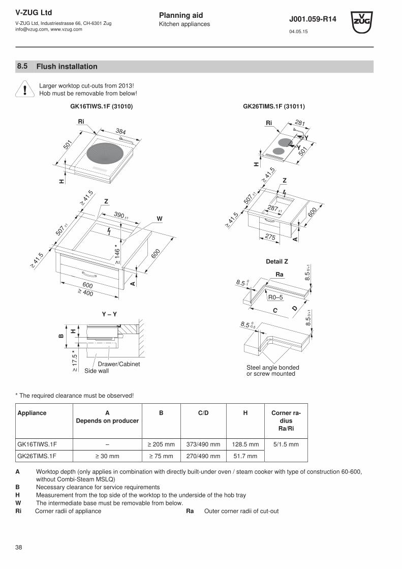
8.5 Flush installation
Larger worktop cut-outs from 2013!Hob must be removable from below!
GK16TIWS.1F (31010) GK26TIMS.1F (31011)
H
384
501
390 ±1
≥ 4
1.5
≥ 4
1.5 600
507
±1
A
Z
600 ≥ 400
≥ 1
46 *
Ri
W
501
281
Y
Y
≥ 41,5
≥ 41,5
507 ±1
600
287 ±1
A
275
Ri
H
Z
C D
Ra
R0–5
8.5 0
-1
8.5 0
-0.5
8.5
0/+
18.5
0/+
1
Steel angle bonded or screw mounted
Detail Z
H≥
17.5
*
Y – Y
B
Drawer/Cabinet
Side wall
* The required clearance must be observed!
Appliance ADepends on producer
B C/D H Corner ra-diusRa/Ri
GK16TIWS.1F – ≥ 205 mm 373/490 mm 128.5 mm 5/1.5 mm
GK26TIMS.1F ≥ 30 mm ≥ 75 mm 270/490 mm 51.7 mm
A Worktop depth (only applies in combination with directly built-under oven / steam cooker with type of construction 60-600,without Combi-Steam MSLQ)
B Necessary clearance for service requirementsH Measurement from the top side of the worktop to the underside of the hob trayW The intermediate base must be removable from below.Ri Corner radii of appliance Ra Outer corner radii of cut-out
V-ZUG LtdV-ZUG Ltd, Industriestrasse 66, CH-6301 [email protected], www.vzug.com
Planning aidKitchen appliances
J001.059-R1404.05.15
39
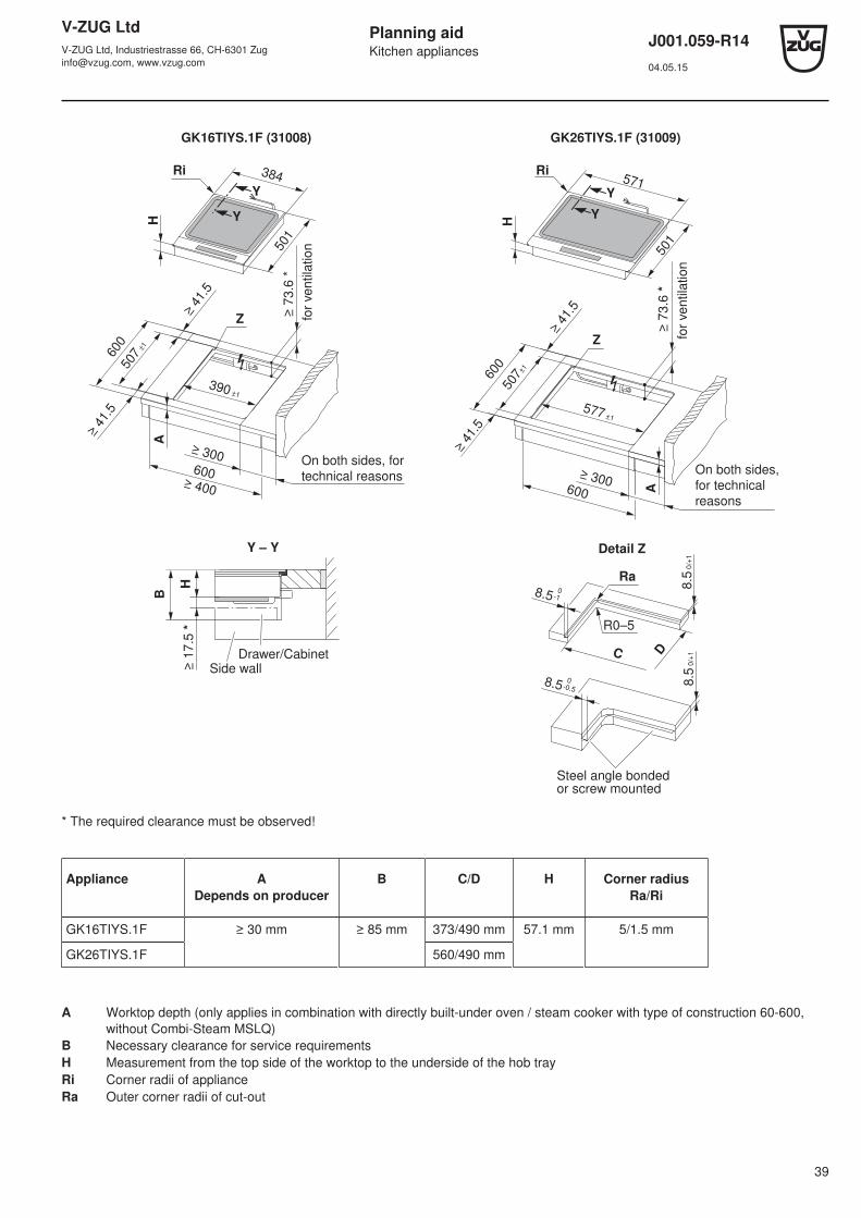
GK16TIYS.1F (31008) GK26TIYS.1F (31009)H
384
501
Y
Y
600 ≥ 400
≥ 4
1.5
600
≥ 4
1.5
Z
≥ 7
3.6
*
≥ 300
507 ±
1
390 ±1
A
Ri
for
ve
ntila
tio
n
On both sides, for
technical reasons
501
571
H
Y
Y
600 A
Z
600
≥ 300
577 ±1
507±
1
Ri
≥
73.6
*
for
ventila
tion
On both sides,
for technical
reasons
≥ 4
1.5
≥ 4
1.5
H≥
17.5
*
Y – Y
B
Drawer/Cabinet
Side wall
C D
Ra
R0–5
8.5 0
-1
8.5 0
-0.58.5
0/+
18.5
0/+
1
Steel angle bonded or screw mounted
Detail Z
* The required clearance must be observed!
Appliance ADepends on producer
B C/D H Corner radiusRa/Ri
GK16TIYS.1F ≥ 30 mm ≥ 85 mm 373/490 mm 57.1 mm 5/1.5 mm
GK26TIYS.1F 560/490 mm
A Worktop depth (only applies in combination with directly built-under oven / steam cooker with type of construction 60-600,without Combi-Steam MSLQ)
B Necessary clearance for service requirementsH Measurement from the top side of the worktop to the underside of the hob trayRi Corner radii of applianceRa Outer corner radii of cut-out

V-ZUG LtdV-ZUG Ltd, Industriestrasse 66, CH-6301 [email protected], www.vzug.com
Planning aidKitchen appliances
J001.059-R1404.05.15
40
GK26TIMS.2F (31001) GK37TIMSF (31041), GK46TIMS.1F (31014)
600
501
384Ri
H
390 ±1
≥ 4
1.5
Z
600
507
±1
≥ 4
1.5
=
=
A
507
±1
577 ±1
600
≥ 4
1.5
≥ 4
1.5
A
600
571
501
Y
YX
X
Ri
Z
H
H≥
17.5
*
Y – Y
B
Drawer/Cabinet
Side wall
C D
Ra
R0–5
8.5 0
-1
8.5 0
-0.58.5
0/+
18.5
0/+
1
Steel angle bonded or screw mounted
Detail Z
* The required clearance must be observed!
Appliance ADepends on produ-
cer
B C/D H Corner radiusRa/Ri
GK 26TIMS.2F ≥ 30 mm ≥ 75 mm 373/490 mm 51.7 mm 5/1.5 mm
GK37TIMSF,GK46TIMS.1F
560/490 mm
A Worktop depth (only applies in combination with directly built-under oven / steam cooker with type of construction 60-600,without Combi-Steam MSLQ)
B Necessary clearance for service requirementsH Measurement from the top side of the worktop to the underside of the hob trayRi Corner radii of applianceRa Outer corner radii of cut-out
V-ZUG LtdV-ZUG Ltd, Industriestrasse 66, CH-6301 [email protected], www.vzug.com
Planning aidKitchen appliances
J001.059-R1404.05.15
41
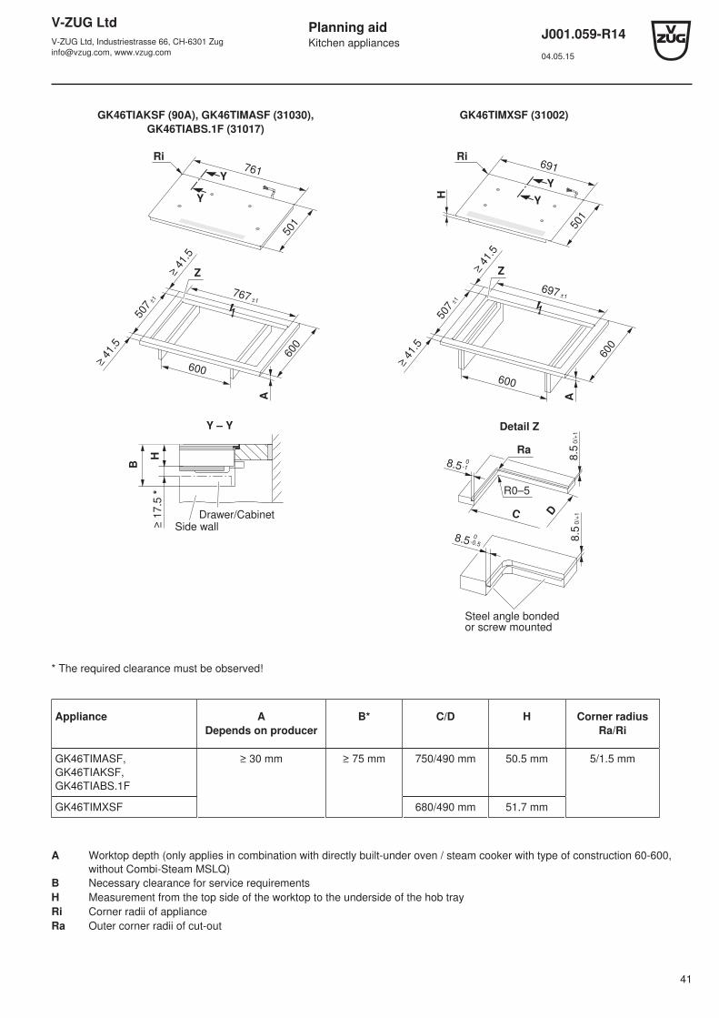
GK46TIAKSF (90A), GK46TIMASF (31030),GK46TIABS.1F (31017)
GK46TIMXSF (31002)
501
761Y
Y
507
±1
≥ 4
1.5
≥ 4
1.5
600
767 ±1
600
A
Z
Ri
501
691
Y
Y
A
507
±1
≥ 4
1.5
≥ 4
1.5
600
Z
697 ±1
600
Ri
H
H≥
17.5
*
Y – Y
B
Drawer/Cabinet
Side wall
C D
Ra
R0–5
8.5 0
-1
8.5 0
-0.5
8.5
0/+
18.5
0/+
1
Steel angle bonded or screw mounted
Detail Z
* The required clearance must be observed!
Appliance ADepends on producer
B* C/D H Corner radiusRa/Ri
GK46TIMASF,GK46TIAKSF,GK46TIABS.1F
≥ 30 mm ≥ 75 mm 750/490 mm 50.5 mm 5/1.5 mm
GK46TIMXSF 680/490 mm 51.7 mm
A Worktop depth (only applies in combination with directly built-under oven / steam cooker with type of construction 60-600,without Combi-Steam MSLQ)
B Necessary clearance for service requirementsH Measurement from the top side of the worktop to the underside of the hob trayRi Corner radii of applianceRa Outer corner radii of cut-out
V-ZUG LtdV-ZUG Ltd, Industriestrasse 66, CH-6301 [email protected], www.vzug.com
Planning aidKitchen appliances
J001.059-R1404.05.15
42
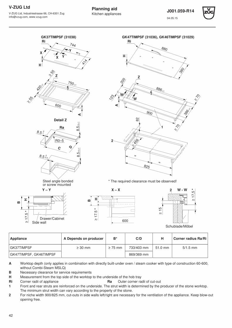
GK37TIMPSF (31038) GK47TIMPSF (31036), GK46TIMPSF (31029)H
744
414
Y
Y
X
X
420
±1
≥ 5
5
≥ 5
5
750 ±1
600
A
Z
Ri
380
880
H
W
W
2
123
A
886 ±1
≥ 7
0
386
±1
200
Z
≥ 7
0
900
82
825
=
=
≥ 4
56
1
Ri
* The required clearance must be observed!
C D
Ra
R0–5
8.5 0
-1
8.5 0
-0.5
8.5
0/+
18.5
0/+
1
Steel angle bonded or screw mounted
Detail Z
H≥
17.5
*
Y – Y
B
Drawer/Cabinet
Side wall
B
≥ 1
7.5
*
600
H
X – X W - W
≥ 1
5
≥ 1
7,5
*2
Schublade/Möbel
Appliance A Depends on producer B* C/D H Corner radius Ra/Ri
GK37TIMPSF ≥ 30 mm ≥ 75 mm 733/403 mm 51.0 mm 5/1.5 mm
GK47TIMPSF, GK46TIMPSF 869/369 mm
A Worktop depth (only applies in combination with directly built-under oven / steam cooker with type of construction 60-600,without Combi-Steam MSLQ)
B Necessary clearance for service requirementsH Measurement from the top side of the worktop to the underside of the hob trayRi Corner radii of appliance Ra Outer corner radii of cut-out1 Front and rear struts are reinforced on the underside. The strut width is determined by the producer of the stone worktop.
The minimum strut width can vary according to the property of the stone.2 For niche width 900/825 mm, cut-outs in side walls left/right are necessary for the ventilation of the appliance. Keep blow-out
opening free.

V-ZUG LtdV-ZUG Ltd, Industriestrasse 66, CH-6301 [email protected], www.vzug.com
Planning aidKitchen appliances
J001.059-R1404.05.15
43
GK56TIMS.1F (31020)
501
897
H
900
A
600
903 ±1
≥ 5
0
507 ±
1
≥ 5
0
Y
Y
B
825
=
=
≥ 4
90
2
1
Ri
C D
Ra
R0–5
8.5 0
-1
8.5 0
-0.5
8.5
0/+
18.5
0/+
1
Steel angle bonded or screw mounted
Detail Z
H≥
17.5
*
Y – Y
B
Drawer/Cabinet
Side wall
* The required clearance must be observed!
Appliance ADepends on producer
B C/D H Corner ra-diusRa/Ri
GK56TIMS.1F ≥ 30 mm ≥ 75 mm 886/490 mm 53.3 mm 5/1.5 mm
A Worktop depth (only applies in combination with directly built-under oven / steam cooker with type of construction 60-600,without Combi-Steam MSLQ)
B Necessary clearance for service requirementsH Measurement from the top side of the worktop to the underside of the hob trayRi Corner radii of appliance Ra Outer corner radii of cut-out1 For symmetrical installation, it is not necessary to cut out the side walls.2 Front and rear struts are reinforced on the underside. The strut width is determined by the producer of the stone worktop. The
minimum strut width can vary according to the property of the stone.

V-ZUG LtdV-ZUG Ltd, Industriestrasse 66, CH-6301 [email protected], www.vzug.com
Planning aidKitchen appliances
J001.059-R1404.05.15
44
8.6 Installation without protective plate
Requirements for optimal ventilation:- a front-facing air gap of ≥ 5 mm- a space of ≥ 17.5 mm in height beneath the appliance- a worktop depth of ≥ 20 mm to ≤ 40 mm- a supply of fresh air (≥ 15 mm air gap) is essential for the trouble-free operation of the hob.
GK26TI …, GK36TI …, GK37TI …, GK46TI …
30
≥ 5
≥ 1
7.5
17
.5
(50
)
A ≥
67
.5
≥ 15 600
Air gap over entire cabinet width ≥ 25 cm²
Necessary space below work surface for ventilation
Drawer Fan
GK46TIABS …, GK46TIAKS …, GK46TIMXS …, GK46TIMAS …
*C
≥ 5
5
600
GK56TIMS …
900
825 *C
≥ 5
5
bei N
ische 8
25
Ventilatoren
* Required for flush appliancesA Necessary space below the worktop for the ventilation of the applianceC Cut-out in side walls for disassembly from below, only for flush version

V-ZUG LtdV-ZUG Ltd, Industriestrasse 66, CH-6301 [email protected], www.vzug.com
Planning aidKitchen appliances
J001.059-R1404.05.15
45
GK46TIPS …, GK46TIMPS …, GK47TIMPS …
30
≥ 5
123 B ≥ 200
≥ 15825
900
≥ 1
7.5 1
7.5
*C
≥ 8
0
A ≥
67
.5
B ≥
15
(50
)
Ventilation
discharge
Ventilation
intake
A Necessary space below
work surface for ventilation
Ventilation
intake for
nic
he
82
5
Drawer
GK16TIYS.1F, GK26TIYS.1F
30
≥
5
≥ 15 600 ≥ 1
7.5
56.1
A ≥
73.6
Drawer
Fan
A Necessary space below work surface for ventialtionAir gap over
entire width of cabinet element ≥ 25 cm²
* Required for flush appliancesA Necessary space below the worktop for the ventilation of the applianceB Cut-out in the side walls left and right for the ventilation of the applianceCCut-out in the side walls for disassembly from below, only for flush version
V-ZUG LtdV-ZUG Ltd, Industriestrasse 66, CH-6301 [email protected], www.vzug.com
Planning aidKitchen appliances
J001.059-R1404.05.15
46
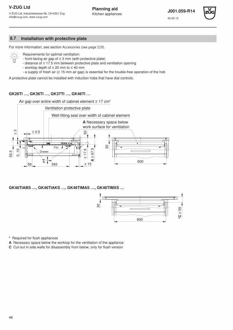
8.7 Installation with protective plate
For more information, see section Accessories ﴾see page 119﴿.
Requirements for optimal ventilation:- front-facing air gap of ≥ 3 mm (with protective plate)- distance of ≥ 17.5 mm between protective plate and ventilation opening- worktop depth of ≥ 20 mm to ≤ 40 mm- a supply of fresh air (≥ 15 mm air gap) is essential for the trouble-free operation of the hob
A protective plate cannot be installed with induction hobs that have dial controls.
GK26TI …, GK36TI …, GK37TI …, GK46TI …
55.5
≥ 3
5..10
≥ 15600
≥ 1
7.5
50
30
A ≥
67.5
≤ 0.5
56
ø4
393
Drawer
Fan
Well-fitting seal over width of cabinet element
Air gap over entire width of cabinet element ≥ 17 cm2
Ventilation protective plate
A Necessary space below
work surface for ventilation
GK46TIABS …, GK46TIAKS …, GK46TIMAS …, GK46TIMXS …
600
30
*C
≥ 5
5
* Required for flush appliancesA Necessary space below the worktop for the ventilation of the applianceC Cut-out in side walls for disassembly from below, only for flush version

V-ZUG LtdV-ZUG Ltd, Industriestrasse 66, CH-6301 [email protected], www.vzug.com
Planning aidKitchen appliances
J001.059-R1404.05.15
47
GK56TIMS …
30
*C
≥ 5
5
825
900
Fans
for
nic
he
82
5
GK46TIPS …, GK46TIMPS …, GK47TIMPS …
55.5
5..10
ø4
≥ 3
≥ 15
825
900
A ≥
67.5
B ≥
15
*C
≥ 8
2
≥ 1
7.5
(50)
30
≤ 0.5
123 B ≥ 200
56 393
Ventilation protective plate
for
nic
he 8
25
Drawer
Ventilation
intake
Ventilation
discharge
A Necessary space below
work surface for ventilation
Ventilationintake
GK16TIYS.1F, GK26TIYS.1F
61.6
≥ 3
5..10
≥ 15
600≥ 1
7.5
30
(56.1
)
*C
55
A ≥
73.6
≤ 0.5
56
ø4
393Drawer
Fan
Well-fitting seal over width of cabinet element
Air gap over entire width of cabinet element ≥ 17 cm2
Ventilation protective plate
A Necessary space below
work surface for ventilation
* Required for flush appliancesA Necessary space below the worktop for the ventilation of the applianceB Cut-out in the side walls left and right for the ventilation of the applianceC Cut-out in side walls for disassembly from below, only for flush version
V-ZUG LtdV-ZUG Ltd, Industriestrasse 66, CH-6301 [email protected], www.vzug.com
Planning aidKitchen appliances
J001.059-R1404.05.15
48
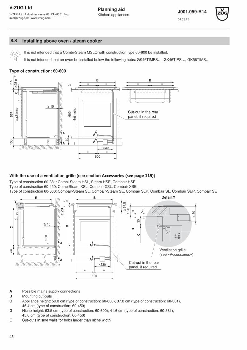
8.8 Installing above oven / steam cooker
It is not intended that a Combi-Steam MSLQ with construction type 60-600 be installed.
It is not intended that an oven be installed below the following hobs: GK46TIMPS…, GK46TIPS…, GK56TIMS…
Type of construction: 60-600
≥ 5
≥ 2
5 c
m²
105
A
A
160
≥ 15
= =B
A
A
=
600
=~230
3 = =B
X
597
applia
nce
600
6/6
nic
he
Cut-out in the rearpanel, if required
With the use of a ventilation grille (see section Accessories ﴾see page 119﴿)Type of construction 60-381: Combi-Steam HSL, Steam HSE, Combair HSEType of construction 60-450: CombiSteam XSL, Combair XSL, Combair XSEType of construction 60-600: Combair-Steam SL, Combair-Steam SE, Combair SLP, Combair SL, Combair SEP, Combair SE
Y
Cvar.
≥ 15
≤ 3
0
≥ 2
0
D3
BE
A
AA
A
= =
600
~230
35
C
5–6
≥ 2
0
3D
≤ 5
0
E
≥ 6
7,5
Ventilation grille
(see «Accessories»)
Cut-out in the rear
panel, if required
Detail Y
A Possible mains supply connectionsB Mounting cut-outsC Appliance height: 59.8 cm (type of construction: 60-600), 37.8 cm (type of construction: 60-381),
45.4 cm (type of construction: 60-450)D Niche height: 63.5 cm (type of construction: 60-600), 41.6 cm (type of construction: 60-381),
45.0 cm (type of construction: 60-450)E Cut-outs in side walls for hobs larger than niche width
V-ZUG LtdV-ZUG Ltd, Industriestrasse 66, CH-6301 [email protected], www.vzug.com
Planning aidKitchen appliances
J001.059-R1404.05.15
49
9 Toptronic glass ceramic hobs
9.1 General notes
The distance between the underside of the hob tray and any part of the cabinet beneath that is made of combustible mater-ial must be ≥ 20 mm. The distance from the hob cut-out to flammable walls (left, right and rear) must be ≥ 50 mm, for flushmounted ≥ 41.5 mm, for GK45TEPSF ≥ 55 mm.
If a drawer is installed directly underneath – and if the tray can be reached from below without the aid of tools – a guardmust be used. The thermal shielding plate set (see Accessories ﴾see page 119﴿) is recommended for this purpose.
Efficient repairs can only be guaranteed if it is possible to uninstall the whole appliance at any time without causing anydamage.
The layout of the hobs to be installed may differ from the hobs illustrated here!
Dear Customer
This planning aid contains the dimensions of all our current glass ceramic hobs.
Since April 2013, most of theflush Toptronic hobs require larger cut-out dimensions and other corner radii. If you own an appliancewhich was manufactured before April 2013, please make sure that you do select the correct cut-out dimensions.The cut-out dimensions for flush Toptronic hobs can be found in section Glass ceramic hobs for the replacement market ﴾see page58﴿.Some replacement appliances with the previous dimensions are still available upon request.
Thank you for reading this information.
Your V-ZUG Ltd
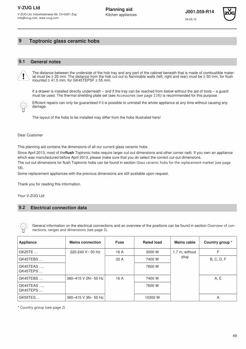
9.2 Electrical connection data
General information on the electrical connections and an overview of the positions can be found in section Overview of con-nections, ranges and dimensions ﴾see page 5﴿.
Appliance Mains connection Fuse Rated load Mains cable Country group *
GK25TE … 220-240 V~ 50 Hz 16 A 3000 W 1.7 m, without plug
F
GK45TEBS … 32 A 7400 W B, C, D, F
GK45TEAS …,GK45TEPS …
7600 W
GK45TEBS … 380–415 V 2N~ 50 Hz 16 A 7400 W A, E
GK45TEAS …,GK45TEPS …
7600 W
GK55TES… 380–415 V 3N~ 50 Hz 10300 W A
* Country group ﴾see page 2﴿
V-ZUG LtdV-ZUG Ltd, Industriestrasse 66, CH-6301 [email protected], www.vzug.com
Planning aidKitchen appliances
J001.059-R1404.05.15
50
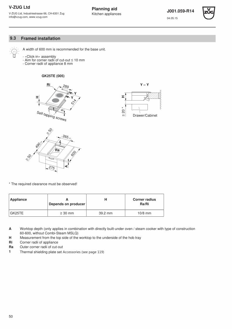
9.3 Framed installation
A width of 600 mm is recommended for the base unit.
- «Click-in» assembly- Aim for corner radii of cut-out ≤ 10 mm - Corner radii of appliance 8 mm
GK25TE (005)
≥ 50
≥ 50
490 ±
1
600
265 ±1
A275
Y
Y
289
514
81
H
Self-tapping screws
Ri
Ra
H≥
20
*
Y – Y
Drawer/Cabinet
* The required clearance must be observed!
Appliance ADepends on producer
H Corner radiusRa/Ri
GK25TE ≥ 30 mm 39.2 mm 10/8 mm
A Worktop depth (only applies in combination with directly built-under oven / steam cooker with type of construction60-600, without Combi-Steam MSLQ)
H Measurement from the top side of the worktop to the underside of the hob trayRi Corner radii of applianceRa Outer corner radii of cut-out1 Thermal shielding plate set Accessories ﴾see page 119﴿

V-ZUG LtdV-ZUG Ltd, Industriestrasse 66, CH-6301 [email protected], www.vzug.com
Planning aidKitchen appliances
J001.059-R1404.05.15
51
GK45TEAS (977), GK45TEASC (977) GK45TEBS.1 (032), GK45TEBS.1C (032)
B60
0
A
490 ±
1
≥ 50
≥ 50
750 ±1
600
81
H
774
514
Y
YX
X
Ri
Self-tapping screws
600
600
560 ±1
490 ±
1
≥ 50
≥ 50
A
H
584
514
1
8
X
X
Self-tapping screws
H≥
20 *
Y – Y
Drawer/Cabinet
X – X
≥ 2
0*
550
B
H
Drawer/cabinet
* The required clearance must be observed!
Appliance ADepends on producer
B H Corner radiusRa/Ri
GK45TEAS, GK45TEASC ≥ 30 mm 65.2 mm 45.2 mm 10/8 mm
GK45TEBS.1, GK45TEBS.1C 66.5 mm 46.5 mm
A Worktop depth (only applies in combination with directly built-under oven / steam cooker with type of construction60-600, without Combi-Steam MSLQ)
B Cut-out in side walls (with/without thermal shielding plate set)H Measurement from the top side of the worktop to the underside of the hob trayRi Corner radii of applianceRa Outer corner radii of cut-out1 Thermal shielding plate set Accessories ﴾see page 119﴿
V-ZUG LtdV-ZUG Ltd, Industriestrasse 66, CH-6301 [email protected], www.vzug.com
Planning aidKitchen appliances
J001.059-R1404.05.15
52
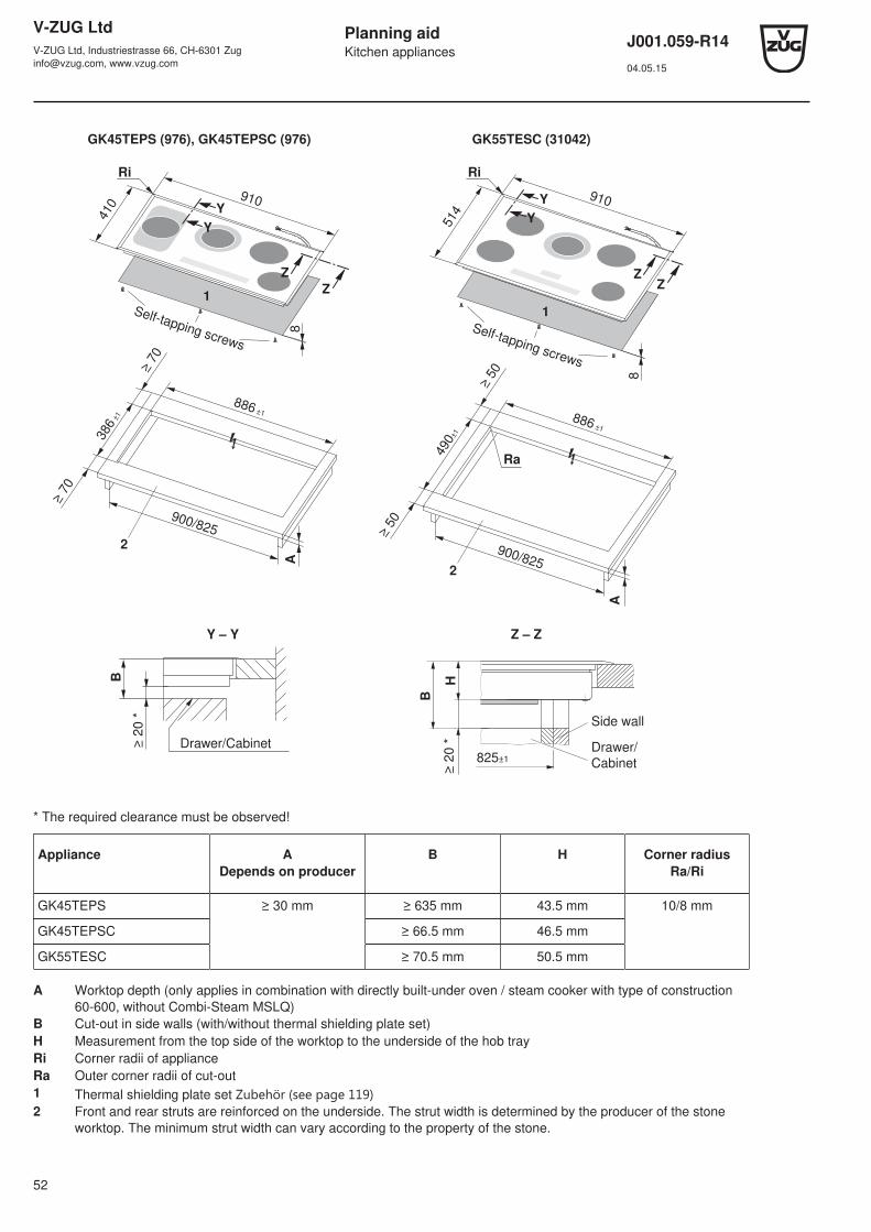
GK45TEPS (976), GK45TEPSC (976) GK55TESC (31042)
A
886 ±1
386 ±
1
900/825
≥ 7
0
≥ 7
0
Y
Y
910
81
410
2
Z
Z
Self-tapping screws
Ri
A
886 ±1
490±
1
900/825
≥ 5
0
≥ 5
0
910
8
1
514
2
Y
Y
ZZ
Self-tapping screws
Ri
Ra
Y – Y
≥ 2
0 *
B
Drawer/Cabinet
B
825±1
≥ 20 *
Z – Z
H
Drawer/
Cabinet
Side wall
* The required clearance must be observed!
Appliance ADepends on producer
B H Corner radiusRa/Ri
GK45TEPS ≥ 30 mm ≥ 635 mm 43.5 mm 10/8 mm
GK45TEPSC ≥ 66.5 mm 46.5 mm
GK55TESC ≥ 70.5 mm 50.5 mm
A Worktop depth (only applies in combination with directly built-under oven / steam cooker with type of construction60-600, without Combi-Steam MSLQ)
B Cut-out in side walls (with/without thermal shielding plate set)H Measurement from the top side of the worktop to the underside of the hob trayRi Corner radii of applianceRa Outer corner radii of cut-out1 Thermal shielding plate set Zubehör ﴾see page 119﴿2 Front and rear struts are reinforced on the underside. The strut width is determined by the producer of the stone
worktop. The minimum strut width can vary according to the property of the stone.

V-ZUG LtdV-ZUG Ltd, Industriestrasse 66, CH-6301 [email protected], www.vzug.com
Planning aidKitchen appliances
J001.059-R1404.05.15
53
9.4 Flush installation
Larger worktop cut-outs from 2013!
If a drawer is installed directly underneath – and if the tray can be reached from below without the aid of tools – an interme-diate base must be used.
A width of 600 mm is recommended for the base unit.Access to the hob from below must be guaranteed. For servicing, the hob control unit can be exchanged from below.
GK25TE.1F (31023)
≥ 4
1.5
≥ 4
1.5 600
275
A
507 ±
1
287 ±1Z
Y
Y
501
X
H
Ri 281
X
C D
Ra
R0–5
8.5 0-1
8.5 0-0.5
Detail Z
8.5
0/+
18
.5 0
/+1
Steel angle bonded
or screw mounted
X – X
≥ 2
0 *
275/500
B
H
Side wall
Drawer/Cabinet
Y – Y
H≥
20 *
B
Side wall
Drawer/Cabinet
* The required clearance must be observed!
Appliance ADepends on producer
B C/D H Corner radiusRa/Ri
GK25TE.1F ≥ 30 mm ≥ 90 mm 270/490 mm 47.5 mm 5/1.5 mm
A Worktop depth (only applies in combination with directly built-under oven / steam cooker with type of construction 60-600,without Combi-Steam MSLQ)
B Minimum measurement in side wall area for disassembly of hob trayH Measurement from the top side of the worktop to the underside of the hob trayRi Corner radii of applianceRa Outer corner radii of cut-out

V-ZUG LtdV-ZUG Ltd, Industriestrasse 66, CH-6301 [email protected], www.vzug.com
Planning aidKitchen appliances
J001.059-R1404.05.15
54
GK45TEAS.1F (31026) GK45TEBS.2F (31028)
761
501
H
Y
Y
Ri
507
±1
≥ 4
1.5
≥ 4
1.5
767 ±1
600
Z600
A
B
X
X
571
501
600
577 ±1
507
±1
≥ 4
1.5
≥ 4
1.5
Z
600
A
H
Ri
C D
Ra
R0–5
8.5 0-1
8.5 0-0.5
Detail Z
8.5
0/+
18
.5 0
/+1
Steel angle bonded
or screw mounted
X – X
≥ 2
0 *
275/500
B
H
Side wall
Drawer/Cabinet
Y – Y
H≥
20 *
B
Side wall
Drawer/Cabinet
* The required clearance must be observed!
Appliance ADepends on producer
B C/D H Corner radiusRa/Ri
GK45TEAS.1F ≥ 30 mm ≥ 90 mm 750/490 mm 47.5 mm 5/1.5 mm
GK45TEBS.2F 560/490 mm
A Worktop depth (only applies in combination with directly built-under oven / steam cooker with type of construction 60-600,without Combi-Steam MSLQ)
B Minimum measurement in side wall area for disassembly of hob trayH Measurement from the top side of the worktop to the underside of the hob trayRi Corner radii of applianceRa Outer corner radii of cut-out
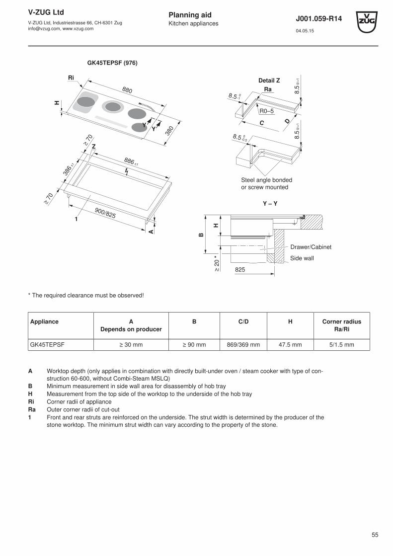
V-ZUG LtdV-ZUG Ltd, Industriestrasse 66, CH-6301 [email protected], www.vzug.com
Planning aidKitchen appliances
J001.059-R1404.05.15
55
GK45TEPSF (976)
A
886 ±1
386
±1
900/825
Z
≥ 7
0
≥ 7
0
1
YY
380
880
Ri
H
C D
Ra
R0–5
8.5 0-1
8.5 0-0.5
Detail Z
8.5
0/+
18
.5 0
/+1
Steel angle bonded
or screw mounted
B
825≥ 20 *
Y – Y
H
Drawer/Cabinet
Side wall
* The required clearance must be observed!
Appliance ADepends on producer
B C/D H Corner radiusRa/Ri
GK45TEPSF ≥ 30 mm ≥ 90 mm 869/369 mm 47.5 mm 5/1.5 mm
A Worktop depth (only applies in combination with directly built-under oven / steam cooker with type of con-struction 60-600, without Combi-Steam MSLQ)
B Minimum measurement in side wall area for disassembly of hob trayH Measurement from the top side of the worktop to the underside of the hob trayRi Corner radii of applianceRa Outer corner radii of cut-out1 Front and rear struts are reinforced on the underside. The strut width is determined by the producer of the
stone worktop. The minimum strut width can vary according to the property of the stone.
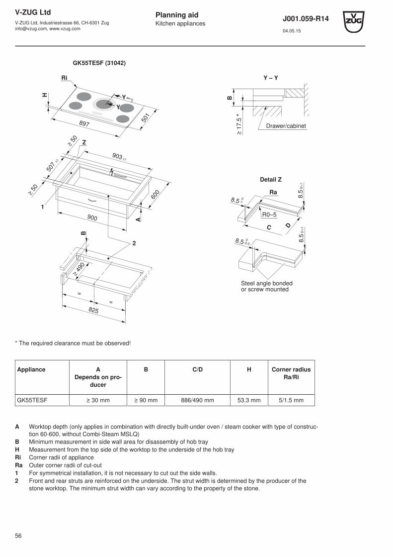
V-ZUG LtdV-ZUG Ltd, Industriestrasse 66, CH-6301 [email protected], www.vzug.com
Planning aidKitchen appliances
J001.059-R1404.05.15
56
GK55TESF (31042)
900
A
600
903 ±1
≥ 5
0
507 ±
1
≥ 5
0
B
825
=
=
≥ 4
90
2
1
501
897
H Y
Y
Z
Ri
≥ 1
7.5
*
B
Y – Y
Drawer/cabinet
C D
Ra
R0–5
8.5 0
-1
8.5 0
-0.5
8.5
0/+
18.5
0/+
1
Steel angle bonded or screw mounted
Detail Z
* The required clearance must be observed!
Appliance ADepends on pro-
ducer
B C/D H Corner radiusRa/Ri
GK55TESF ≥ 30 mm ≥ 90 mm 886/490 mm 53.3 mm 5/1.5 mm
A Worktop depth (only applies in combination with directly built-under oven / steam cooker with type of construc-tion 60-600, without Combi-Steam MSLQ)
B Minimum measurement in side wall area for disassembly of hob trayH Measurement from the top side of the worktop to the underside of the hob trayRi Corner radii of applianceRa Outer corner radii of cut-out1 For symmetrical installation, it is not necessary to cut out the side walls.2 Front and rear struts are reinforced on the underside. The strut width is determined by the producer of the
stone worktop. The minimum strut width can vary according to the property of the stone.
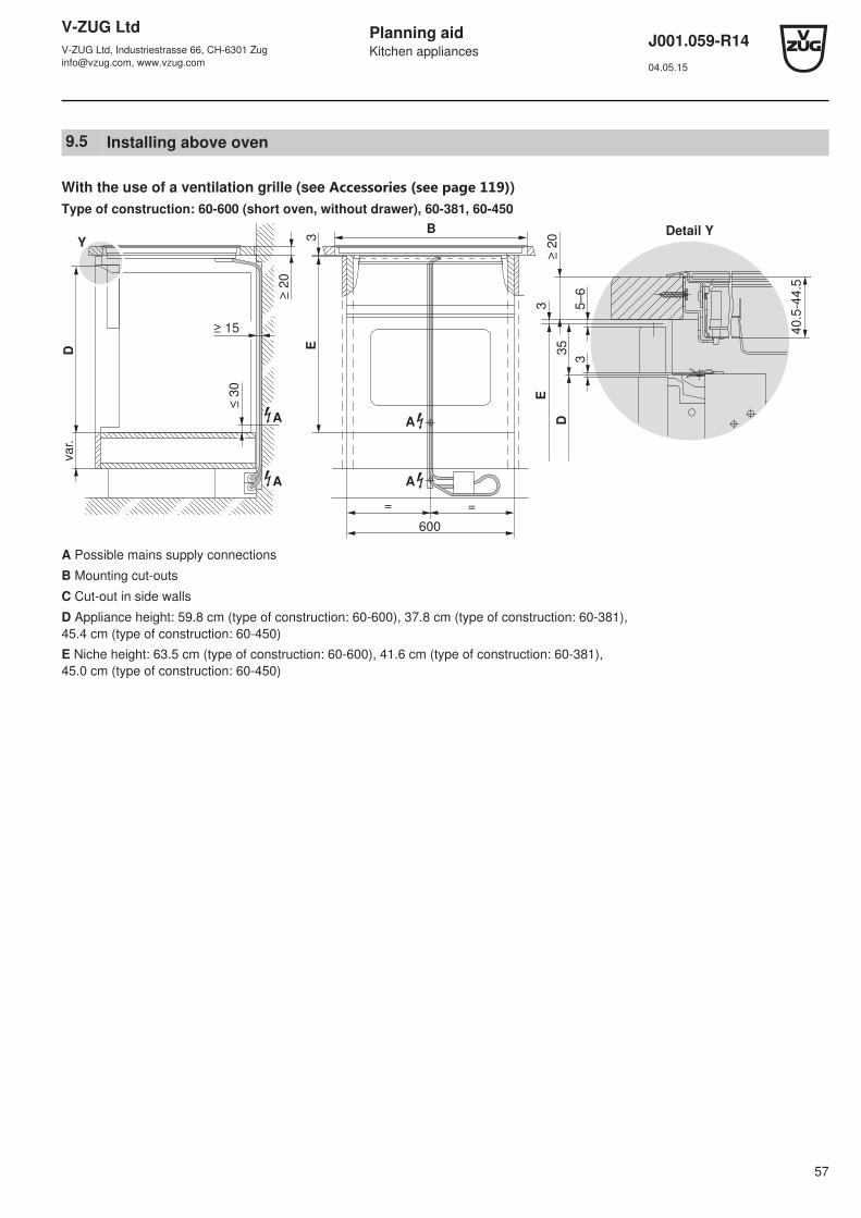
V-ZUG LtdV-ZUG Ltd, Industriestrasse 66, CH-6301 [email protected], www.vzug.com
Planning aidKitchen appliances
J001.059-R1404.05.15
57
9.5 Installing above oven
With the use of a ventilation grille (see Accessories ﴾see page 119﴿)Type of construction: 60-600 (short oven, without drawer), 60-381, 60-450
E
D3
5
3
3≥
20
40
.5-4
4.5
5–
6
600
= =
3
B
≥ 2
0
≥ 15
≤ 3
0
va
r.
Y
D
E
A
AA
A
Detail Y
A Possible mains supply connections
B Mounting cut-outs
C Cut-out in side walls
D Appliance height: 59.8 cm (type of construction: 60-600), 37.8 cm (type of construction: 60-381), 45.4 cm (type of construction: 60-450)
E Niche height: 63.5 cm (type of construction: 60-600), 41.6 cm (type of construction: 60-381), 45.0 cm (type of construction: 60-450)
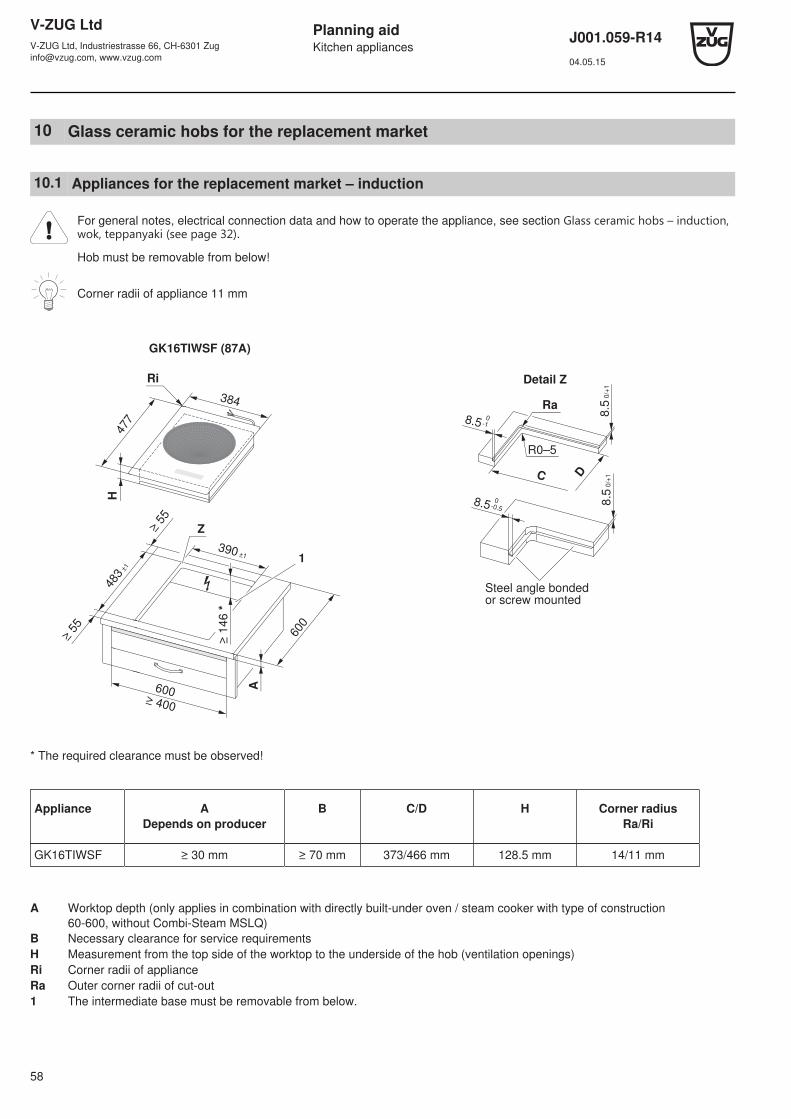
V-ZUG LtdV-ZUG Ltd, Industriestrasse 66, CH-6301 [email protected], www.vzug.com
Planning aidKitchen appliances
J001.059-R1404.05.15
58
10 Glass ceramic hobs for the replacement market
10.1 Appliances for the replacement market – induction
For general notes, electrical connection data and how to operate the appliance, see section Glass ceramic hobs – induction,wok, teppanyaki ﴾see page 32﴿.
Hob must be removable from below!
Corner radii of appliance 11 mm
GK16TIWSF (87A)
H
384
477
390 ±1
≥ 5
5
≥ 5
5
600
483
±1
A
Z
600 ≥ 400
≥ 1
46 *
Ri
1
C D
Ra
R0–5
8.5 0
-1
8.5 0
-0.5
8.5
0/+
18.5
0/+
1
Steel angle bonded or screw mounted
Detail Z
* The required clearance must be observed!
Appliance ADepends on producer
B C/D H Corner radiusRa/Ri
GK16TIWSF ≥ 30 mm ≥ 70 mm 373/466 mm 128.5 mm 14/11 mm
A Worktop depth (only applies in combination with directly built-under oven / steam cooker with type of construction60-600, without Combi-Steam MSLQ)
B Necessary clearance for service requirementsH Measurement from the top side of the worktop to the underside of the hob (ventilation openings)Ri Corner radii of applianceRa Outer corner radii of cut-out1 The intermediate base must be removable from below.

V-ZUG LtdV-ZUG Ltd, Industriestrasse 66, CH-6301 [email protected], www.vzug.com
Planning aidKitchen appliances
J001.059-R1404.05.15
59
GK16TIYSF (85A) GK26TIYSF (86A)H
384
477
Y
Y
600 ≥ 400
≥ 5
5600
≥ 5
5
Z ≥
73.6
*
≥ 300
483
±1
390 ±1
ARi
for
ventila
tion
On both sides
for technical
reasons
477
547
H
Y
Y
600 A
Z
≥ 5
5
600
≥ 5
5 ≥ 300
553 ±1
483
±1
Ri
On both sides
for technical
reasons
for
ventila
tion
≥
73.6
*
Y – Y
H≥
17.5
*
B
Drawer/Cabinet
Side wall
C D
Ra
R0–5
8.5 0
-1
8.5 0
-0.58.5
0/+
18.5
0/+
1
Steel angle bonded or screw mounted
Detail Z
* The required clearance must be observed!
Appliance ADepends on producer
B C/D H Corner radiusRa/Ri
GK16TIYSF ≥ 30 mm ≥ 85 mm 373/466 mm 57.1 mm 14/11 mm
GK26TIYSF 536/466 mm
A Worktop depth (only applies in combination with directly built-under oven / steam cooker with type of construction60-600, without Combi-Steam MSLQ)
B Necessary clearance for service requirementsH Measurement from the top side of the worktop to the underside of the hob (ventilation openings)Ri Corner radii of applianceRa Outer corner radii of cut-out

V-ZUG LtdV-ZUG Ltd, Industriestrasse 66, CH-6301 [email protected], www.vzug.com
Planning aidKitchen appliances
J001.059-R1404.05.15
60
GK26TIMSF (84A) GK36TISF (008)
477
272
Y
Y
≥ 55
≥ 55
483 ±1
600278±1
A275
RiH
Z
483
±1
553 ±1
600
≥ 5
5
≥ 5
5
A
600
547
477
Y
Y
Ri
Z
H
Y – Y
H≥
17.5
*
B
Drawer/Cabinet
Side wall
C D
Ra
R0–5
8.5 0
-1
8.5 0
-0.5
8.5
0/+
18.5
0/+
1
Steel angle bonded or screw mounted
Detail Z
* The required clearance must be observed!
Appliance ADepends on producer
B C/D H Corner radiusRa/Ri
GK26TIMSF ≥ 30 mm ≥ 75 mm 261/466 mm 50.0 mm 14/11 mm
GK36TISF 536/466 mm 51.7 mm
A Worktop depth (only applies in combination with directly built-under oven / steam cooker with type of construction60-600, without Combi-Steam MSLQ)
B Necessary clearance for service requirementsH Measurement from the top side of the worktop to the underside of the hob (ventilation openings)Ri Corner radii of applianceRa Outer corner radii of cut-out
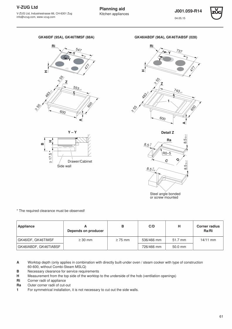
V-ZUG LtdV-ZUG Ltd, Industriestrasse 66, CH-6301 [email protected], www.vzug.com
Planning aidKitchen appliances
J001.059-R1404.05.15
61
GK46IDF (95A), GK46TIMSF (88A) GK46IABDF (96A), GK46TIABSF (028)
483
±1
553 ±1600
≥ 5
5
≥ 5
5
A
600
547
477
Y
Y
Ri
Z
H
483
±1
≥ 5
5
≥ 5
5
600
743 ±1
600
A
Z
477
737Y
Y
Ri
1
H
Y – Y
H≥
17.5
*
B
Drawer/Cabinet
Side wall
C D
Ra
R0–5
8.5 0
-1
8.5 0
-0.5
8.5
0/+
18.5
0/+
1
Steel angle bonded or screw mounted
Detail Z
* The required clearance must be observed!
Appliance ADepends on producer
B C/D H Corner radiusRa/Ri
GK46IDF, GK46TIMSF ≥ 30 mm ≥ 75 mm 536/466 mm 51.7 mm 14/11 mm
GK46IABDF, GK46TIABSF 726/466 mm 50.0 mm
A Worktop depth (only applies in combination with directly built-under oven / steam cooker with type of construction60-600, without Combi-Steam MSLQ)
B Necessary clearance for service requirementsH Measurement from the top side of the worktop to the underside of the hob (ventilation openings)Ri Corner radii of applianceRa Outer corner radii of cut-out1 For symmetrical installation, it is not necessary to cut out the side walls.
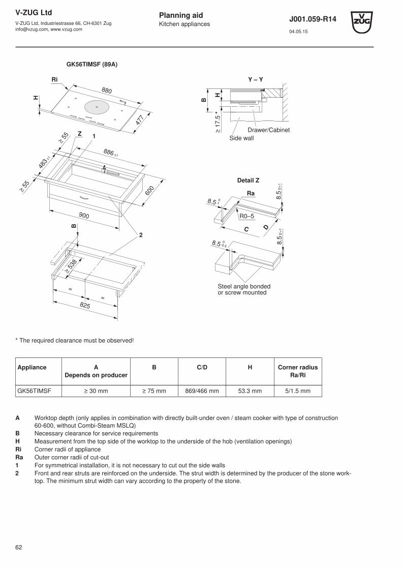
V-ZUG LtdV-ZUG Ltd, Industriestrasse 66, CH-6301 [email protected], www.vzug.com
Planning aidKitchen appliances
J001.059-R1404.05.15
62
GK56TIMSF (89A)
477
880
H
900
600
886 ±1
≥ 5
5
483
±1
≥ 5
5
Z1
B
825
=
=
≥ 5
38
2
Ri Y – Y
H≥
17.5
*
B
Drawer/Cabinet
Side wall
C D
Ra
R0–5
8.5 0
-1
8.5 0
-0.5
8.5
0/+
18.5
0/+
1
Steel angle bonded or screw mounted
Detail Z
* The required clearance must be observed!
Appliance ADepends on producer
B C/D H Corner radiusRa/Ri
GK56TIMSF ≥ 30 mm ≥ 75 mm 869/466 mm 53.3 mm 5/1.5 mm
A Worktop depth (only applies in combination with directly built-under oven / steam cooker with type of construction60-600, without Combi-Steam MSLQ)
B Necessary clearance for service requirementsH Measurement from the top side of the worktop to the underside of the hob (ventilation openings)Ri Corner radii of applianceRa Outer corner radii of cut-out1 For symmetrical installation, it is not necessary to cut out the side walls2 Front and rear struts are reinforced on the underside. The strut width is determined by the producer of the stone work-
top. The minimum strut width can vary according to the property of the stone.
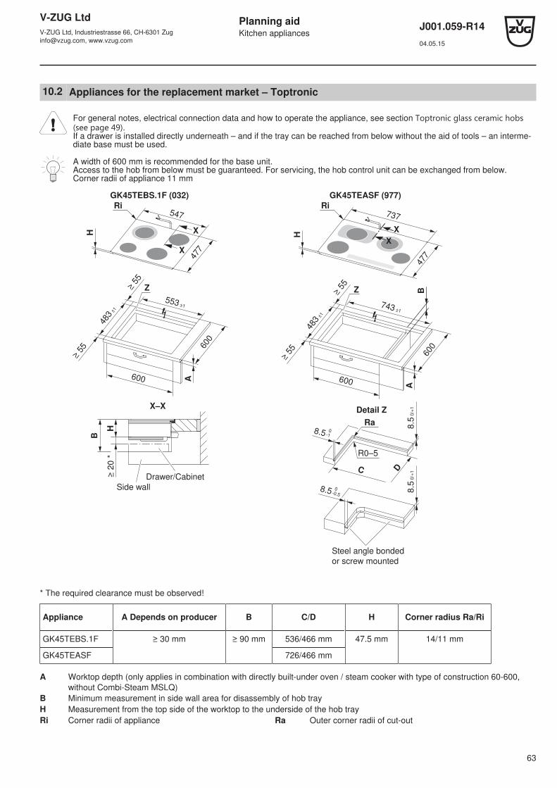
V-ZUG LtdV-ZUG Ltd, Industriestrasse 66, CH-6301 [email protected], www.vzug.com
Planning aidKitchen appliances
J001.059-R1404.05.15
63
10.2 Appliances for the replacement market – Toptronic
For general notes, electrical connection data and how to operate the appliance, see section Toptronic glass ceramic hobs﴾see page 49﴿.If a drawer is installed directly underneath – and if the tray can be reached from below without the aid of tools – an interme-diate base must be used.
A width of 600 mm is recommended for the base unit.Access to the hob from below must be guaranteed. For servicing, the hob control unit can be exchanged from below.Corner radii of appliance 11 mm
GK45TEBS.1F (032) GK45TEASF (977)
547
477X
X
600
553 ±1
483
±1
≥ 5
5
≥ 5
5
Z
600
A
H
Ri
737
X
X
477
483
±1
≥ 5
5
≥ 5
5
743 ±1
600
Z
600
A
B
H
Ri
X–X
H≥
20 *
B
Side wall
Drawer/CabinetC D
Ra
R0–5
8.5 0-1
8.5 0-0.5
Detail Z8
.5 0
/+1
8.5
0/+
1
Steel angle bonded
or screw mounted
* The required clearance must be observed!
Appliance A Depends on producer B C/D H Corner radius Ra/Ri
GK45TEBS.1F ≥ 30 mm ≥ 90 mm 536/466 mm 47.5 mm 14/11 mm
GK45TEASF 726/466 mm
A Worktop depth (only applies in combination with directly built-under oven / steam cooker with type of construction 60-600, without Combi-Steam MSLQ)
B Minimum measurement in side wall area for disassembly of hob trayH Measurement from the top side of the worktop to the underside of the hob trayRi Corner radii of appliance Ra Outer corner radii of cut-out
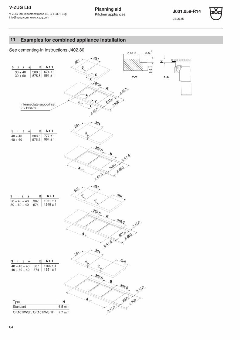
V-ZUG LtdV-ZUG Ltd, Industriestrasse 66, CH-6301 [email protected], www.vzug.com
Planning aidKitchen appliances
J001.059-R1404.05.15
64
11 Examples for combined appliance installation
S i z e B A ± 1
30 + 40 388.5 674 ± 1 30 + 60 575.5 861 ± 1
S i z e B A ± 1
40 + 40 388.5 777 ± 1 40 + 60 575.5 964 ± 1
S i z e B A ± 1
30 + 40 + 40 387 1061 ± 1 30 + 60 + 40 574 1248 ± 1
S i z e B A ± 1
40 + 40 + 40 387 1164 ± 1 40 + 60 + 40 574 1351 ± 1
Y-Y
Intermediate support set2 × H63789
281
B
3
285.5
A ±1
384
B
3
388.5
A±1
281
B
384 3
3
285.5
388.5
A±1
384
384
B
3
3
388.5
388.5
501
≥ 600 507±1
≥ 41.5
≥ 41.5
501
507±1
≥ 41.5
≥ 41.5 ≥ 600
501
507±1
≥ 600
≥ 41.5
≥ 41.5
501
507±1
≥ 600
≥ 41.5
≥ 41.5
A±1
≥ 41.5
8.5 0
-1
Y
Y
X
X
H
X-X
Type
Standard
H
GK16TIWSF, GK16TIWS.1F
6.5 mm
7.7 mm
See cementing-in instructions J402.80
8.5
0 -1
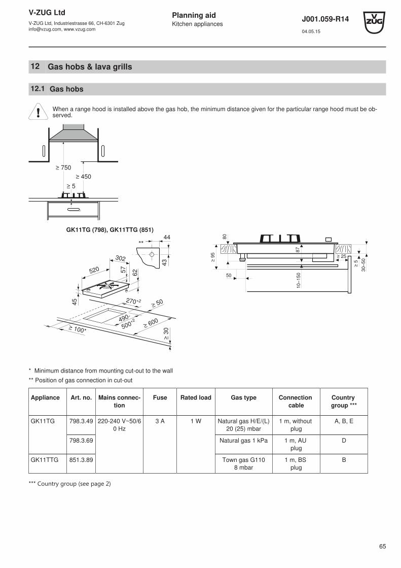
V-ZUG LtdV-ZUG Ltd, Industriestrasse 66, CH-6301 [email protected], www.vzug.com
Planning aidKitchen appliances
J001.059-R1404.05.15
65
12 Gas hobs & lava grills
12.1 Gas hobs
When a range hood is installed above the gas hob, the minimum distance given for the particular range hood must be ob-served.
≥ 750
≥ 450
≥ 5
GK11TG (798), GK11TTG (851)
520
45
57
62
44
43
≥ 50
≥ 100*≥ 600
≥ 3
0
270+2
490-
500+2
302
80
≥ 9
5
87
≥ 5
≥ 25
10
–1
5050
30
–5
0
* Minimum distance from mounting cut-out to the wall
** Position of gas connection in cut-out
Appliance Art. no. Mains connec-tion
Fuse Rated load Gas type Connection cable
Country group ***
GK11TG 798.3.49 220-240 V~50/60 Hz
3 A 1 W Natural gas H/E/(L)20 (25) mbar
1 m, without plug
A, B, E
798.3.69 Natural gas 1 kPa 1 m, AU plug
D
GK11TTG 851.3.89 Town gas G1108 mbar
1 m, BS plug
B
*** Country group ﴾see page 2﴿
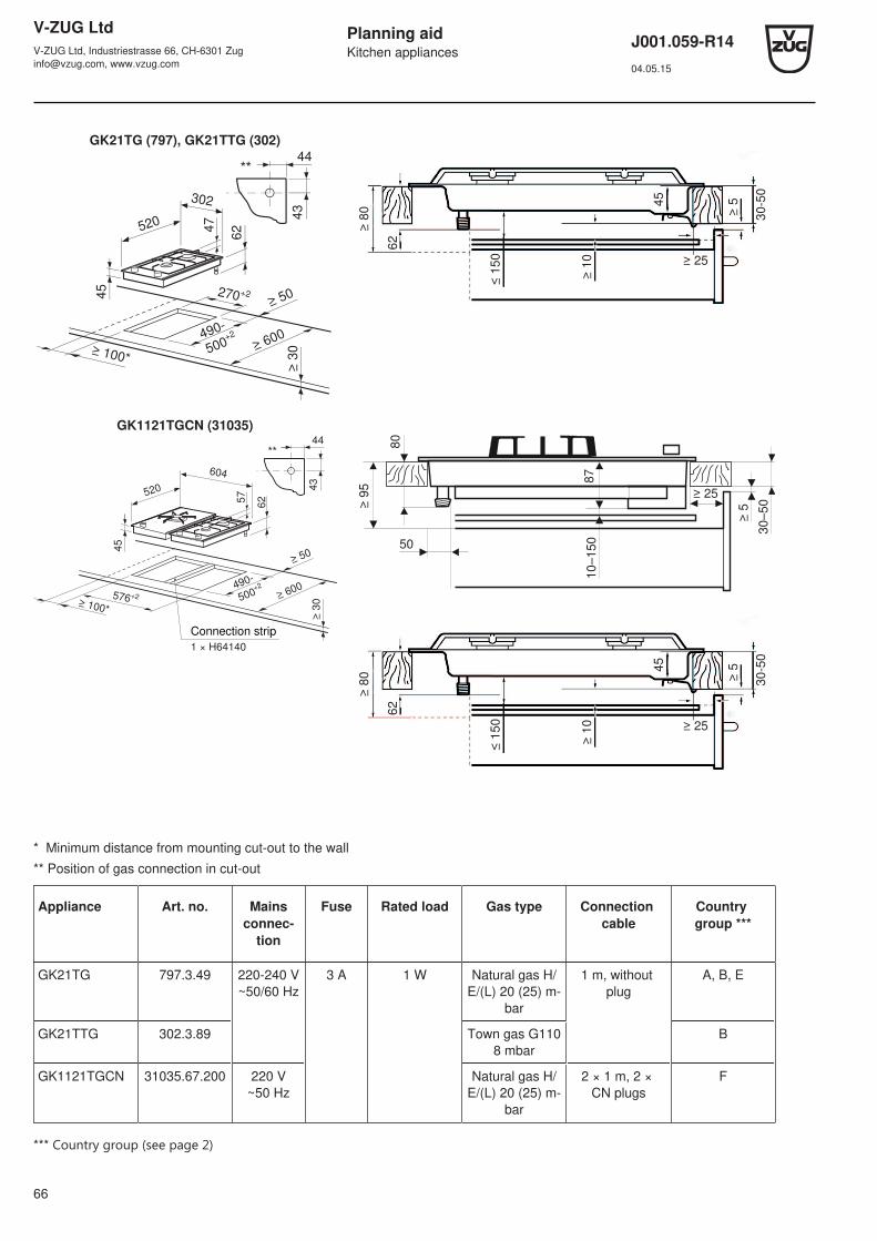
V-ZUG LtdV-ZUG Ltd, Industriestrasse 66, CH-6301 [email protected], www.vzug.com
Planning aidKitchen appliances
J001.059-R1404.05.15
66
GK21TG (797), GK21TTG (302)
520
3024
7
62
44
43
≥ 50≥
30≥ 600490-
500+2
270+2
≥ 100*
45
≤ 1
50
≥ 1
0 ≥ 25
45
30
-50
62
≥ 8
0 ≥ 5
GK1121TGCN (31035)
520
45
57
62
44
43
≥ 50
≥ 100*
≥ 600
≥ 3
0
576+2
490-
500+2
604
Connection strip
1 × H64140
80
≥ 9
5
87
≥ 5
≥ 25
10–15
050
30–5
0
≤ 1
50
≥ 1
0 ≥ 25
45
30
-50
62
≥ 8
0 ≥ 5
* Minimum distance from mounting cut-out to the wall
** Position of gas connection in cut-out
Appliance Art. no. Mainsconnec-
tion
Fuse Rated load Gas type Connection cable
Country group ***
GK21TG 797.3.49 220-240 V~50/60 Hz
3 A 1 W Natural gas H/E/(L) 20 (25) m-
bar
1 m, without plug
A, B, E
GK21TTG 302.3.89 Town gas G1108 mbar
B
GK1121TGCN 31035.67.200 220 V~50 Hz
Natural gas H/E/(L) 20 (25) m-
bar
2 × 1 m, 2 × CN plugs
F
*** Country group ﴾see page 2﴿

V-ZUG LtdV-ZUG Ltd, Industriestrasse 66, CH-6301 [email protected], www.vzug.com
Planning aidKitchen appliances
J001.059-R1404.05.15
67
GK41TG (717)
602
520
45
47
53
≥ 50
≥ 3
0≥ 600
26
21
≥ 100*490
±1560±1
≤ 1
50
≥ 1
0
≥ 25
45
30
-50
50
≥ 8
0 ≥ 5
35
GK51TPG (701)
520
912
45
≥ 150*
≥ 3
0
≥ 50
595
7
42
26
≥ 600490
±1850±1
≤ 1
50
≥ 1
0 ≥ 25
45
30-5
0
60
≥ 8
0 ≥ 5
* Minimum distance from mounting cut-out to the wall
** Position of gas connection in cut-out
Appliance Art. no. Mains connec-tion
Fuse Rated load Gas type Connection cable
Country group ***
GK41TG 717.3.49 220-240 V~50/60 Hz
3 A 1 W Natural gas H/E/(L)20 (25) mbar
1 m, without plug
A, B, E
GK51TPG 701.3.49
701.3.69 Natural gas 1 kPa 1 m, AU plug
D
*** Country group ﴾see page 2﴿

V-ZUG LtdV-ZUG Ltd, Industriestrasse 66, CH-6301 [email protected], www.vzug.com
Planning aidKitchen appliances
J001.059-R1404.05.15
68
12.2 Lava grill, GK11TKLG (98A)
≥ 100*
≥ 3
0
≥ 50
490-500
+2
520
≥ 6
00
302
10
8D
rain
co
ck
~1
28
*
≥ 60-5
0270 +2
17
3
* Minimum distance from cut-out for trough to wall
Appliance Art. no. Mains connection Rated load Mains cable Connection cable Country group **
GK11TKLG 98A.3.30 220-240 V~50/60 Hz 13 A 2400 W 1 m, without plug A, B, E, F
12.3 2-zone induction hob, GK21TI (834)
53
≥ 600
≥ 40
≥ 50
≥ 60/50
520
302
270 +2-0
490-
500+2
-0
20/3
0*
* with oven
Appliance Art. no. Mains connection Fuse Rated load Connection cable Country group **
GK21TI 834.3.89 220-240 V~50/60 Hz 16 A 3700 W 1.1 m, without plug
A, B, E, F
** Country group ﴾see page 2﴿

V-ZUG LtdV-ZUG Ltd, Industriestrasse 66, CH-6301 [email protected], www.vzug.com
Planning aidKitchen appliances
J001.059-R1404.05.15
69
12.4 Installation examples for combined gas edition arrangement
Arrangement A (1 × H64140)
30
28830
30288
30288
490 / 500
600
50
R3
≥ 50
30 576+230
36
H64140
Connection strip
Arrangement B (2 × H64140)
30
30
30
30 882+23030
30288
30288
30306
490 / 500
600
50
R3
≥ 5036
H64140
Connection strip
The connection strip H64140 is not included in the scope of delivery and must be ordered separately for a combined install-ation.

V-ZUG LtdV-ZUG Ltd, Industriestrasse 66, CH-6301 [email protected], www.vzug.com
Planning aidKitchen appliances
J001.059-R1404.05.15
70
Arrangement C (3 × H64140)
30
30 1188+23030
30
30
30
30
30288
30288
30306490 / 500
600
50
R3
≥ 50
30306
36
H64140
Connection strip
Arrangement D (1 × H64140)
30
876+2
60
30
30288
490 / 500
600
50
R3
≥ 50
60588
60
36
H64140
Connection strip
The connection strip H64140 is not included in the scope of delivery and must be ordered separately for a combined install-ation.
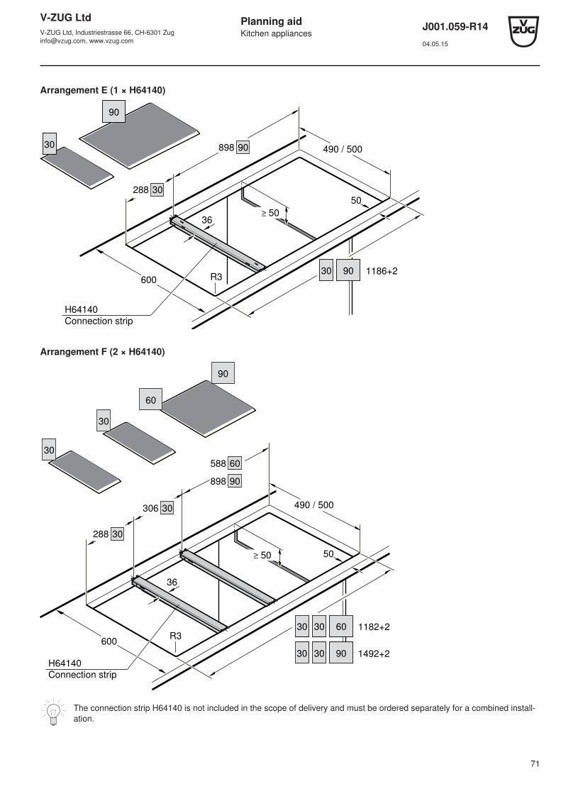
V-ZUG LtdV-ZUG Ltd, Industriestrasse 66, CH-6301 [email protected], www.vzug.com
Planning aidKitchen appliances
J001.059-R1404.05.15
71
Arrangement E (1 × H64140)
30
1186+2
90
30
30288
490 / 500
600
50
R3
≥ 50
90898
90
36
H64140
Connection strip
Arrangement F (2 × H64140)
30
60
30
30288
490 / 500
600
50
R3
≥ 50
60588
60
90898
30306
30
90
1182+230
30 90 1492+230
36
H64140
Connection strip
The connection strip H64140 is not included in the scope of delivery and must be ordered separately for a combined install-ation.
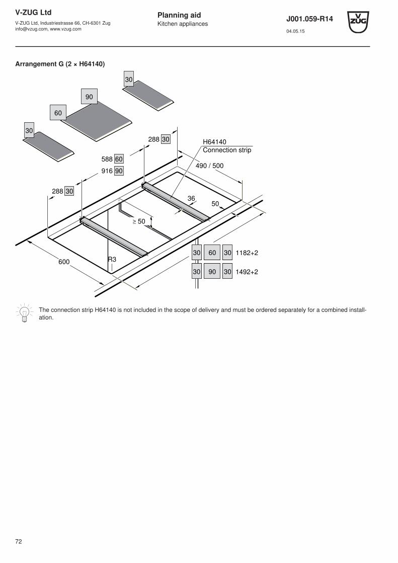
V-ZUG LtdV-ZUG Ltd, Industriestrasse 66, CH-6301 [email protected], www.vzug.com
Planning aidKitchen appliances
J001.059-R1404.05.15
72
Arrangement G (2 × H64140)
30
60
30
30288
490 / 500
600
50
R3
≥ 50
60588
60
90916
30
90
1182+230
30 90 1492+230
30288
36
H64140
Connection strip
The connection strip H64140 is not included in the scope of delivery and must be ordered separately for a combined install-ation.
V-ZUG LtdV-ZUG Ltd, Industriestrasse 66, CH-6301 [email protected], www.vzug.com
Planning aidKitchen appliances
J001.059-R1404.05.15
73
13 Range hoods
Technical information on the range hoods can be found in the document J328.35 «TechInfo for range hoods» and the pricelist.
13.1 General notes
If other firing systems are being used at the same time (e.g. wood, gas, oil or coal fired heating appliances), safe operationis only possible providing a room negative pressure of 4 Pa (0.04 mbar) is not exceeded at the location of the appliance.Risk of toxic fumes! An adequate flow of fresh air must be guaranteed e.g. via non-closable openings in doors or windowsand in combination with an air-intake/exhaust-air wall box or by other technical means.
If the appliance is installed over gas hobs, each cooking zone must be fitted with an ignition fuse and the minimum dis-tances (see «Distance above hob») must be adhered to.
Efficient repairs can only be guaranteed if it is possible to uninstall the whole appliance at any time without causing anydamage.
Extraction mode
The extracted air must not be fed into a chimney which is used for exhausting fumes from appliances burning gas or otherfuels.Observe the local fire regulations.
Installation notes• In addition to the correct dimensioning of the exhaust duct, it is also necessary to ensure a sufficient inflow of fresh air.
Exhaust air needs fresh air.
• Avoid routing the exhaust duct to the side through the flue casing.
• Planning features for non-destructive de-installation and maintenance of the appliance:
– Do not route telescopic casing in suspended ceilings.
– Avoid silicon joints between the telescopic casing and the appliance.
– All plastering, plasterboarding, wall papering or painting work is to be carried out prior to installing the appliance.
13.2 Ceiling range hoods
Applicable to the following hoods:
• For activation of external motor flaps, roof ventilators, room fans, etc., see document P60.008.
• Mains connection directly above range hood, connection cable 1.2 m with plug.
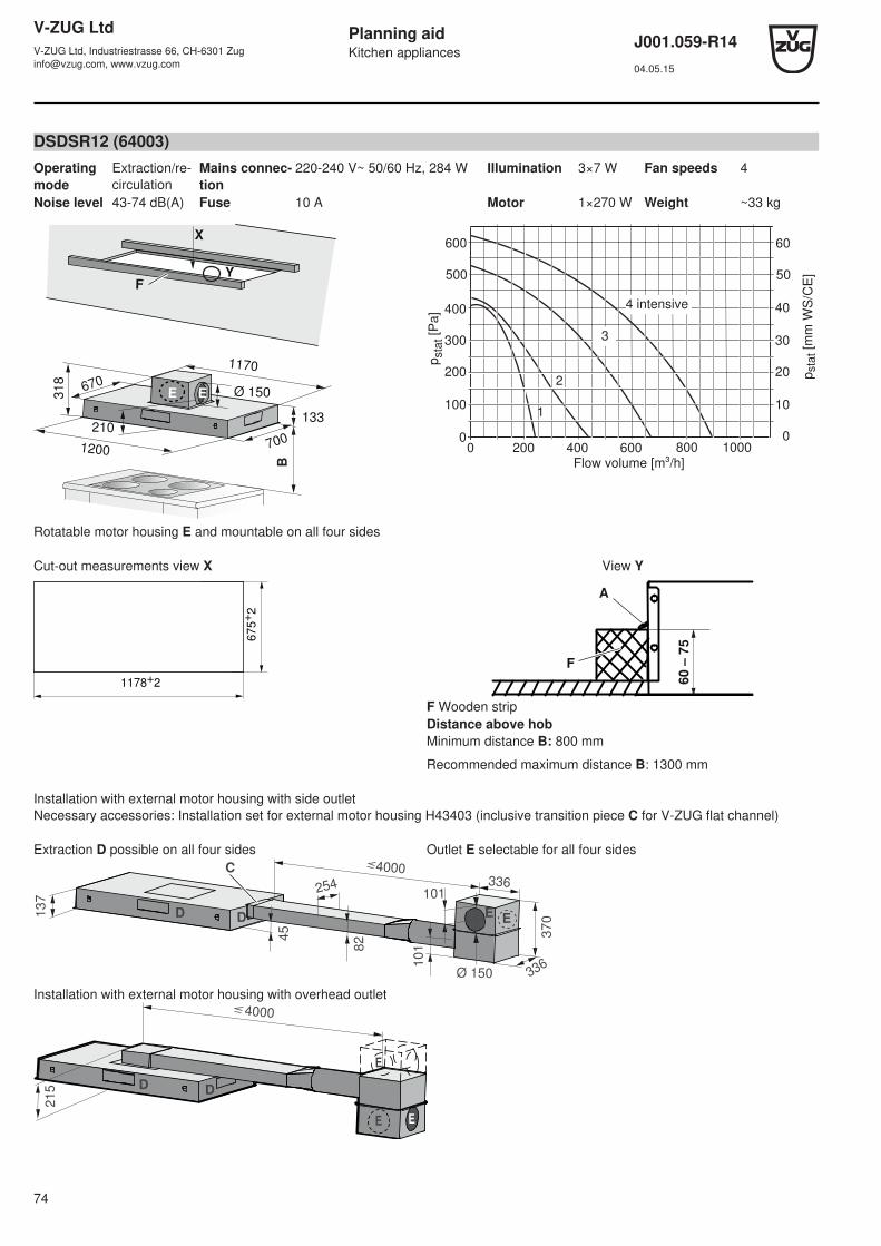
V-ZUG LtdV-ZUG Ltd, Industriestrasse 66, CH-6301 [email protected], www.vzug.com
Planning aidKitchen appliances
J001.059-R1404.05.15
74
DSDSR12 (64003)Operatingmode
Extraction/re-circulation
Mains connec-tion
220-240 V~ 50/60 Hz, 284 W Illumination 3×7 W Fan speeds 4
Noise level 43-74 dB(A) Fuse 10 A Motor 1×270 W Weight ~33 kg
Ø 150
1200
1170
31
8
670
700210
X
YB
133
EE
F
pst
at [
Pa]
100
200
300
400
0
Flow volume [m³/h]200 400 6000
pst
at [
mm
WS
/CE
]
10
20
30
40
0
500 50
600 60
800 1000
1
2
3
4 intensive
Rotatable motor housing E and mountable on all four sides
Cut-out measurements view X
1178+
2
67
5+
2
View Y
60
– 7
5
F
A
F Wooden stripDistance above hobMinimum distance B: 800 mm
Recommended maximum distance B: 1300 mm
Installation with external motor housing with side outletNecessary accessories: Installation set for external motor housing H43403 (inclusive transition piece C for V-ZUG flat channel)
Extraction D possible on all four sides Outlet E selectable for all four sides
13
7
4000
254
45
82
101
101336
336Ø 150
37
0EED D
C
Installation with external motor housing with overhead outlet4000
215 D
D
E
E
E
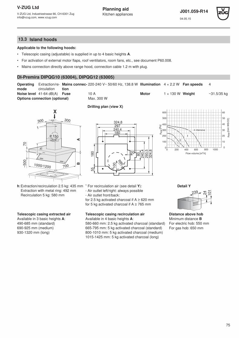
V-ZUG LtdV-ZUG Ltd, Industriestrasse 66, CH-6301 [email protected], www.vzug.com
Planning aidKitchen appliances
J001.059-R1404.05.15
75
13.3 Island hoods
Applicable to the following hoods:
• Telescopic casing (adjustable) is supplied in up to 4 basic heights A.
• For activation of external motor flaps, roof ventilators, room fans, etc., see document P60.008.
• Mains connection directly above range hood, connection cable 1.2 m with plug.
DI-Premira DIPQG10 (63004), DIPQG12 (63005)Operatingmode
Extraction/re-circulation
Mains connec-tion
220-240 V~ 50/60 Hz, 138.8 W Illumination 4 × 2.2 W Fan speeds 4
Noise level 41-64 dB(A) Fuse 10 A Motor 1 × 130 W Weight ~31.5/35 kgOptions connection (optional) Max. 300 W
Drilling plan (view X)
ø 150
700
X
BA
1000/1200
h
300300
~500
70
1
324,8297
240,4180
80
240,4
293,5
324,820
180
55 1
00
R80
pst
at [
Pa
]
100
200
300
400
0
Flow volume [m³/h]
200 400 6000
pst
at [
mm
WS
/CE
]
10
20
30
40
0
500 50
600 60
800 1000
12
3
4 intensive
h:Extraction/recirculation 2.5 kg: 435 mmExtraction with metal ring: 492 mmRecirculation 5 kg: 580 mm
¹ For recirculation air (see detail Y):- Air outlet left/right: always possible- Air outlet front/back:for 2.5 kg activated charcoal if A ≥ 620 mmfor 5 kg activated charcoal if A ≥ 765 mm
Detail Y
24
10
1
239
Telescopic casing extracted airAvailable in 3 basic heights A:490-685 mm (standard)690-925 mm (medium)930-1320 mm (long)
Telescopic casing recirculation airAvailable in 4 basic heights A:580-660 mm: 2.5 kg activated charcoal (standard)665-795 mm: 5 kg activated charcoal (standard)800-1010 mm: 5 kg activated charcoal (medium)1015-1425 mm: 5 kg activated charcoal (long)
Distance above hobMinimum distance BFor electric hob: 550 mmFor gas hob: 650 mm
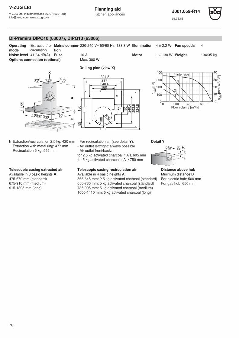
V-ZUG LtdV-ZUG Ltd, Industriestrasse 66, CH-6301 [email protected], www.vzug.com
Planning aidKitchen appliances
J001.059-R1404.05.15
76
DI-Premira DIPQ10 (63007), DIPQ13 (63006)Operatingmode
Extraction/re-circulation
Mains connec-tion
220-240 V~ 50/60 Hz, 138.8 W Illumination 4 × 2.2 W Fan speeds 4
Noise level 41-64 dB(A) Fuse 10 A Motor 1 × 130 W Weight ~34/35 kgOptions connection (optional) Max. 300 W
Drilling plan (view X)
55
BA
ø 150
1000/1300 700
h
X
330330
¹
324.8297
240.4180
80
240
.4
293
.5
324
.820
18
05
5 10
0
R80
200
100
00 200 400 600
0
10
20
30
40
Flow volume [m³/h]
pst
at [
Pa
]
p sta
t [m
m W
S/C
E]
300
400
3
2
1
4 intensive
h:Extraction/recirculation 2.5 kg: 420 mmExtraction with metal ring: 477 mmRecirculation 5 kg: 565 mm
¹ For recirculation air (see detail Y):- Air outlet left/right: always possible- Air outlet front/back:for 2.5 kg activated charcoal if A ≥ 605 mmfor 5 kg activated charcoal if A ≥ 750 mm
Detail Y
24
10
1
239
Telescopic casing extracted airAvailable in 3 basic heights A:475-670 mm (standard)675-910 mm (medium)915-1305 mm (long)
Telescopic casing recirculation airAvailable in 4 basic heights A:565-645 mm: 2.5 kg activated charcoal (standard)650-780 mm: 5 kg activated charcoal (standard)785-995 mm: 5 kg activated charcoal (medium)1000-1410 mm: 5 kg activated charcoal (long)
Distance above hobMinimum distance BFor electric hob: 500 mmFor gas hob: 650 mm

V-ZUG LtdV-ZUG Ltd, Industriestrasse 66, CH-6301 [email protected], www.vzug.com
Planning aidKitchen appliances
J001.059-R1404.05.15
77
DIB10 (816), DIB12 (63008)Operatingmode
Extraction/re-circulation
Mains connec-tion
220-240 V~ 50/60 Hz, 640 W Illumination 4 × 20 W, 12 V~ Fan speeds 4
Noise level 40-59 dB(A) Fuse 10 A Motor 1 × 260 W Weight ~36 kgOptions connection Max. 300 W
Drilling plan (view X)
0 200 400 600 800
400
300
200
100
0
40
30
20
10
0
1
23
4
pst
at [
mm
WS
/CE
]
pst
at [
Pa
]
Flow volume [m³/h]
Intensive
25
10
0
Detail Y
16668
BA
ø 150
1000/1200 700
44
0
X
299257
ø 10
ø 102
15
16
4
88
25
7
207
299
235
For recirculation
air, see detail Y
for air outlet
Telescopic casing extracted airAvailable in 3 basic heights A:
Telescopic casing recirculation airAvailable in 3 basic heights A:
Distance above hobMinimum distance B
550-745 mm (standard)750-1000 mm (medium)1000-1250 mm (long)
600-745 mm (standard)750-1000 mm (medium)1000-1250 mm (long)
For electric hob: 600 mmFor gas hob: 750 mm

V-ZUG LtdV-ZUG Ltd, Industriestrasse 66, CH-6301 [email protected], www.vzug.com
Planning aidKitchen appliances
J001.059-R1404.05.15
78
DIB14 (821)Operatingmode
Extraction/re-circulation
Mains connec-tion
220-240 V~ 50/60 Hz, 680 W Illumination 6 × 20 W, 12 V~ Fan speeds 4
Noise level 40-59 dB(A) Fuse 10 A Motor 1 × 260 W Weight ~45 kgOptions connection Max. 300 W
Drilling plan (view X)
0 200 400 600 800
400
300
200
100
0
40
30
20
10
0
1
23
4
pst
at [
mm
WS
/CE
]
pst
at [
Pa
]
Flow volume [m³/h]
Intensive
25
10
0
Detail Y
166
80
BA
X
299257
ø 10
ø 102
15
16
4
88
25
7
207
299
235
ø 150
45
3
1400 700
For recirculation
air, see Detail Y
for air outlets
Telescopic casing extracted airAvailable in 3 basic heights A:
Telescopic casing recirculation airAvailable in 3 basic heights A:
Distance above hobMinimum distance B
562-757 mm (standard)762-1012 mm (medium)1012-1262 mm (long)
612-757 mm (standard)762-1012 mm (medium)1012-1262 mm (long)
For electric hob: 600 mmFor gas hob: 750 mm

V-ZUG LtdV-ZUG Ltd, Industriestrasse 66, CH-6301 [email protected], www.vzug.com
Planning aidKitchen appliances
J001.059-R1404.05.15
79
DISE10 (076), DISE12 (077)Operatingmode
Extraction/re-circulation
Mains connec-tion
220-240 V~ 50/60 Hz, 455 W Illumination 4 × 20 W, 12 V~ Fan speeds 4
Noise level 44-64 dB(A) Fuse 10 A Motor 1 × 175 W Weight ~21/23 kgOptions connection Max. 200 W
Drilling plan (view X)
0 100 200 300 400 500 6000
100
200
300
400
500
2
10
10
20
30
40
50
pst
at [
mm
WS
/CE
]
pst
at [
Pa
]
4
3
Flow volume [m³/h]
Intensive
Detail Y
36
77
135
273
276.5
236.4
190
14
8
25
222
2506001000/1200
B
60
A ²
31
6 ¹
X
277277
ø 150
45
8
¹ with metal ring: 356 mm² grid spacing: 10 mm
For recirculation air left/right or front/back as option, see detail Y for air outlet
Telescopic casing extracted airAvailable in 3 basic heights A:
Telescopic casing recirculation airAvailable in 3 basic heights A:
Distance above hobMinimum distance B
550-750 mm (standard)750-905 mm (medium)905-1265 mm (long)
650-750 mm (standard)750-980 mm (medium)980-1340 mm (long)
For electric hob: 600 mmFor gas hob: 750 mm
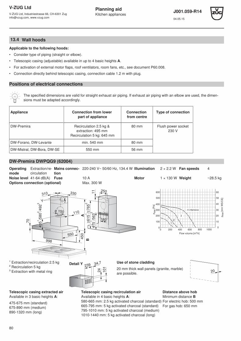
V-ZUG LtdV-ZUG Ltd, Industriestrasse 66, CH-6301 [email protected], www.vzug.com
Planning aidKitchen appliances
J001.059-R1404.05.15
80
13.4 Wall hoods
Applicable to the following hoods:
• Consider type of piping (straight or elbow).
• Telescopic casing (adjustable) available in up to 4 basic heights A.
• For activation of external motor flaps, roof ventilators, room fans, etc., see document P60.008.
• Connection directly behind telescopic casing, connection cable 1.2 m with plug.
Positions of electrical connections
The specified dimensions are valid for straight exhaust air piping. If exhaust air piping with an elbow are used, the dimen-sions must be adapted accordingly.
Appliance Connection from lower part of appliance
Connection from centre
Type of connection
DW-Premira Recirculation 2.5 kg & extraction: 495 mm
Recirculation 5 kg: 645 mm
80 mm Flush power socket230 V
DW-Forano, DW-Levante min. 540 mm 80 mm
DW-Mistral, DW-Bora, DW-SE 550 mm 56 mm
DW-Premira DWPQG9 (62004)Operatingmode
Extraction/re-circulation
Mains connec-tion
220-240 V~ 50/60 Hz, 134.4 W Illumination 2 × 2.2 W Fan speeds 4
Noise level 41-64 dB(A) Fuse 10 A Motor 1 × 130 W Weight ~28.5 kgOptions connection (optional) Max. 300 W
25011
415
1
/563
2110
≥615
1
/≥765
2
ø 150
435
1
/580
2
/492
3
70
998
550
B
A
330310
180
450
Y
pst
at [
Pa]
100
200
300
400
0
Flow volume [m³/h]
200 400 6000
pst
at [
mm
WS
/CE
]10
20
30
40
0
500 50
600 60
800 1000
12
3
4 intensive
¹ Extraction/recirculation 2.5 kg² Recirculation 5 kg³ Extraction with metal ring 2
4
101
Detail Y 34,7239
Use of stone cladding
20 mm thick wall panels (granite, marble)are possible. 20
Telescopic casing extracted airAvailable in 3 basic heights A:
475-675 mm (standard)675-890 mm (medium)890-1320 mm (long)
Telescopic casing recirculation airAvailable in 4 basic heights A:580-665 mm: 2.5 kg activated charcoal (standard)665-795 mm: 5 kg activated charcoal (standard)795-1010 mm: 5 kg activated charcoal (medium)1010-1440 mm: 5 kg activated charcoal (long)
Distance above hobMinimum distance BFor electric hob: 500 mmFor gas hob: 650 mm
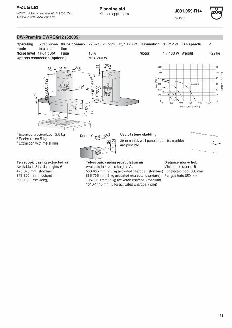
V-ZUG LtdV-ZUG Ltd, Industriestrasse 66, CH-6301 [email protected], www.vzug.com
Planning aidKitchen appliances
J001.059-R1404.05.15
81
DW-Premira DWPQG12 (62005)Operatingmode
Extraction/re-circulation
Mains connec-tion
220-240 V~ 50/60 Hz, 136.6 W Illumination 3 × 2.2 W Fan speeds 4
Noise level 41-64 dB(A) Fuse 10 A Motor 1 × 130 W Weight ~29 kgOptions connection (optional) Max. 300 W
25011
4151
/5632
180
110
≥6151
/≥7652
ø 150
4351
/5802
/4923
70
1198
550
B
A
330310
450
Y
pst
at [
Pa]
100
200
300
400
0
Flow volume [m³/h]
200 400 6000
pst
at [
mm
WS
/CE
]
10
20
30
40
0
500 50
600 60
800 1000
12
3
4 intensive
¹ Extraction/recirculation 2.5 kg² Recirculation 5 kg³ Extraction with metal ring 2
4
101
Detail Y 34,7239
Use of stone cladding
20 mm thick wall panels (granite, marble)are possible. 20
Telescopic casing extracted airAvailable in 3 basic heights A:475-675 mm (standard)675-890 mm (medium)890-1320 mm (long)
Telescopic casing recirculation airAvailable in 4 basic heights A:580-665 mm: 2.5 kg activated charcoal (standard)665-795 mm: 5 kg activated charcoal (standard)795-1010 mm: 5 kg activated charcoal (medium)1010-1440 mm: 5 kg activated charcoal (long)
Distance above hobMinimum distance BFor electric hob: 500 mmFor gas hob: 650 mm

V-ZUG LtdV-ZUG Ltd, Industriestrasse 66, CH-6301 [email protected], www.vzug.com
Planning aidKitchen appliances
J001.059-R1404.05.15
82
DW-Premira DWPQ9 (62007)Operatingmode
Extraction/re-circulation
Mains connec-tion
220-240 V~ 50/60 Hz, 134.4 W Illumination 2 × 2.2 W Fan speeds 4
Noise level 41-64 dB(A) Fuse 10 A Motor 1 × 130 W Weight ~25.5 kgOptions connection (optional) Max. 300 W
110ø 150
42
0 ¹
/56
5 ²
/ 4
77
³
898 550
BA
3303102501
14
00 ¹
/ 5
48 ²
18055
For recirculation air, see detail Y
for air outlet
60
0 ¹
/7
50
²
200
100
00 200 400 600
0
10
30
40
Flow volume [m³/h]
pst
at [
Pa]
pst
at [
mm
WS
/CE
]
300
400
20
3
2
1
4 intensive
¹ Extraction/recirculation 2.5 kg² Recirculation 5 kg³ Extraction with metal ring 2
4
101
Detail Y 34,7239
Use of stone cladding
20 mm thick wall panels (granite, marble)are possible. 20
Telescopic casing extracted airAvailable in 3 basic heights A:
460-660 mm (standard)660-875 mm (medium)875-1305 mm (long)
Telescopic casing recirculation airAvailable in 4 basic heights A:565-650 mm: 2.5 kg activated charcoal (standard)650-780 mm: 5 kg activated charcoal (standard)780-995 mm: 5 kg activated charcoal (medium)995-1425 mm: 5 kg activated charcoal (long)
Distance above hobMinimum distance BFor electric hob: 500 mmFor gas hob: 650 mm
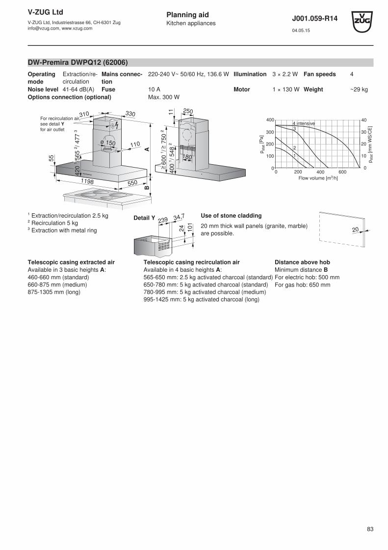
V-ZUG LtdV-ZUG Ltd, Industriestrasse 66, CH-6301 [email protected], www.vzug.com
Planning aidKitchen appliances
J001.059-R1404.05.15
83
DW-Premira DWPQ12 (62006)Operatingmode
Extraction/re-circulation
Mains connec-tion
220-240 V~ 50/60 Hz, 136.6 W Illumination 3 × 2.2 W Fan speeds 4
Noise level 41-64 dB(A) Fuse 10 A Motor 1 × 130 W Weight ~29 kgOptions connection (optional) Max. 300 W
110ø 150
42
0 ¹
/56
5 ²
/ 4
77
³
1198 550
BA
3303102501
14
00
¹/
548
²
18055
60
0 ¹
/ 7
50
²
For recirculation air,see detail Yfor air outlet
200
100
00 200 400 600
0
10
30
40
Flow volume [m³/h]
pst
at [
Pa]
pst
at [
mm
WS
/CE
]
300
400
20
3
2
1
4 intensive
¹ Extraction/recirculation 2.5 kg² Recirculation 5 kg³ Extraction with metal ring 2
4
101
Detail Y 34,7239
Use of stone cladding
20 mm thick wall panels (granite, marble)are possible. 20
Telescopic casing extracted airAvailable in 3 basic heights A:460-660 mm (standard)660-875 mm (medium)875-1305 mm (long)
Telescopic casing recirculation airAvailable in 4 basic heights A:565-650 mm: 2.5 kg activated charcoal (standard)650-780 mm: 5 kg activated charcoal (standard)780-995 mm: 5 kg activated charcoal (medium)995-1425 mm: 5 kg activated charcoal (long)
Distance above hobMinimum distance BFor electric hob: 500 mmFor gas hob: 650 mm

V-ZUG LtdV-ZUG Ltd, Industriestrasse 66, CH-6301 [email protected], www.vzug.com
Planning aidKitchen appliances
J001.059-R1404.05.15
84
DW-Forano DWF8 (042)Operatingmode
Extraction/re-circulation
Mains connec-tion
220-240 V~ 50/60 Hz, 290 W Illumination 2 × 20 W, 12 V~ Fan speeds 4
Noise level 51-66 dB(A) Fuse 10 A Motor 1 × 250 W Weight ~29 kg
285255
ø 1501
7
AB
75
167248
423
46
5.5
49
~7
30
46
0
35
5 ¹
47
0
800
300–540273
For recirculation air, see detail Y for air outlet
¹ For air outlet to the back
0 200 400 600 800
400
300
200
100
0
40
500 50
30
20
10
0
1
3
4
pst
at [
mm
WS
/CE
]
pst
at [
Pa]
2
Flow volume [m³/h]
Intensive
Use of stone cladding
20 mm thick wall panels (granite,marble) are possible. 20
Telescopic casing extracted airAvailable in 2 basic heights A:740-970 mm (standard)970-1274 mm (long)
Telescopic casing recirculationairAvailable in 1 basic height A:1024-1374 mm (long)
Standard version recirculation air:without telescopic casing
Distance above hobMinimum distance B: 650 mm
12614.7
49
76
Detail Y

V-ZUG LtdV-ZUG Ltd, Industriestrasse 66, CH-6301 [email protected], www.vzug.com
Planning aidKitchen appliances
J001.059-R1404.05.15
85
DWSE12 (068)Operatingmode
Extraction/re-circulation
Mains connec-tion
220-240 V~ 50/60 Hz, 435 W Illumination 3 × 20 W, 12 V~ Fan speeds 4
Noise level 44-64 dB(A) Fuse 10 A Motor 1 × 175 W Weight ~20 kgOptions connection Max. 200 W
4771198
240250A
B
60
301
230~576
170
ø 150
458
82
316 ¹
30
For recirculation air, see detail Y for air outlet
* With metal ring: 356 mm
0 100 200 300 400 500 6000
100
200
300
400
500
2
10
10
20
30
40
50
pst
at [
mm
WS
/CE
]
pst
at [
Pa
]
4
3
Flow volume [m³/h]
Intensive
Use of stone cladding
20 mm thick wall panels (granite,marble) are possible. 20
Telescopic casing extracted airAvailable in 2 basic heights A:615-825 mm (standard)615-1125 mm (long)
Telescopic casing recirculationairAvailable in 2 basic heights A:700-825 mm (standard)700-1145 mm (long)
Distance above hobMinimum distance BFor electric hob: 600 mmFor gas hob: 750 mm
36
.5
77
Detail Y 24142
DWVHR9 (62010)Operatingmode
Extraction/re-circulation
Mains connec-tion
220-240 V~ 50/60 Hz, 272 W Illumination 2 × 1.1 W, 12 V~ Fan speeds 4
Noise level 49-73 dB(A) Fuse 10 A Motor 1 × 270 W Weight ~16 kg
200 300
Ø 150
A
45
6
898
5
B
328
280
339
148
415
80
75
164
pst
at [
Pa]
100
200
300
400
0
Flow volume [m³/h]
200 400 6000
pst
at [
mm
WS
/CE
]
10
20
30
40
0
500 50
600 60
800 1000
1
2
3
4 intensive
Use of stone cladding
20 mm thick wall panels (granite, marble)are possible. 20
Telescopic casing extractedairAvailable in 2 basic heights A:805-1095 mm (standard)1090-1435 mm (long)
Standard version recirculation air:without telescopic casing
Distance above hobMinimum distance BFor electric hob: 450 mmFor gas hob: 450 mm

V-ZUG LtdV-ZUG Ltd, Industriestrasse 66, CH-6301 [email protected], www.vzug.com
Planning aidKitchen appliances
J001.059-R1404.05.15
86
DWVMR9 (62009)Operatingmode
Extraction/re-circulation
Mains connec-tion
220-240 V~ 50/60 Hz, 305 W Illumination 2 × 2.5 W, 12 V~ Fan speeds 4
Noise level 50-70 dB(A) Fuse 10 A Motor 1 × 300 W Weight 19 kg
280
240
250
51
0
5
895
AB
22
22
16
49
0
Ø 1
50
325
pst
at [
Pa]
100
200
300
400
0
Flow volume [m³/h]
200 400 6000
pst
at [
mm
WS
/CE
]
10
20
30
40
0
500 50
600 60
800 1000
1
2
3
4 intensive
Use of stone cladding
20 mm thick wall panels (granite,marble) are possible. 20
Telescopic casing extracted airAvailable in basic height A:1045-1465 mm (standard)
Standard version recirculation air:without telescopic casing
Distance above hobMinimum distance BFor electric hob: 400 mmFor gas hob: 500 mm

V-ZUG LtdV-ZUG Ltd, Industriestrasse 66, CH-6301 [email protected], www.vzug.com
Planning aidKitchen appliances
J001.059-R1404.05.15
87
DWB9 (993), DWB12 (994)Operatingmode
Extraction/re-circulation
Mains connec-tion
220-240 V~ 50/60 Hz, 640 W Illumination 4 × 20 W, 12 V~ Fan speeds 4
Noise level 40-59 dB(A) Fuse 10 A Motor 1 × 260 W Weight ~36 kgOptions connection Max. 300 W
147ø 150
440
900/1200 550
BA
3042602151
6450~
700
14071
67
For recirculation air,
see detail Y
for air outlet
0 200 400 600 800
400
300
200
100
0
40
30
20
10
0
1
23
4
pst
at [
mm
WS
/CE
]
pst
at [
Pa
]
Flow volume [m³/h]
Intensive
Use of stone cladding
20 mm thick wall panels (granite,marble) are possible. 20
Telescopic casing extracted airAvailable in 2 basic heights A:500-820 mm (standard)820-1150 mm (long)
Telescopic casing recirculationairAvailable in 2 basic heights A:600-820 mm (standard)820-1150 mm (long)
Distance above hobMinimum distance BFor electric hob: 600 mmFor gas hob: 750 mm
25
10
0
Detail Y
166
DWSE9 (059)Operatingmode
Extraction/re-circulation
Mains connec-tion
220-240 V~ 50/60 Hz, 415 W Illumination 2 × 20 W, 12 V~ Fan speeds 4
Noise level 44-64 dB(A) Fuse 10 A Motor 1 × 175 W Weight ~14 kgOption connection Max. 200 W
477898
240250
AB
60
30
301 230~576
170
ø 15082
31
6 ¹
45
8
For recirculation air, see detail Y for air outlet
* With metal ring: 356 mm
0 100 200 300 400 500 6000
100
200
300
400
500
2
10
10
20
30
40
50
pst
at [
mm
WS
/CE
]
pst
at [
Pa
]
4
3
Flow volume [m³/h]
Intensive
Use of stone cladding
20 mm thick wall panels (granite,marble) are possible. 20
Telescopic casing extracted airAvailable in 2 basic heights A:615-825 mm (standard)615-1125 mm (long)
Telescopic casing recirculationairAvailable in 2 basic heights A:700-825 mm (standard)700-1145 mm (long)
Distance above hobMinimum distance BFor electric hob: 600 mmFor gas hob: 750 mm
36
.5
77
Detail Y 24142

V-ZUG LtdV-ZUG Ltd, Industriestrasse 66, CH-6301 [email protected], www.vzug.com
Planning aidKitchen appliances
J001.059-R1404.05.15
88
13.5 Built-in hoods
Applicable to the following hoods:
• For activation of external motor flaps, roof ventilators, room fans, etc., see document P60.008.
• Connection cable 1.2 m with plug
Positions of electrical connections
The specified dimensions are valid for straight exhaust air piping. If exhaust air piping with an elbow are used, the dimen-sions must be adapted accordingly.
Appliance Connection from floor(plinth height 100 mm)
Connection in niche(from centre to connection)
Type of connection
All models 2050 mm 180 mm Flush power socket 230 V

V-ZUG LtdV-ZUG Ltd, Industriestrasse 66, CH-6301 [email protected], www.vzug.com
Planning aidKitchen appliances
J001.059-R1404.05.15
89
DHL8 (64001), DHL11 (64002)Operatingmode
Extraction/recirculation
Mains connec-tion
220-240 V~ 50/60 Hz, 200 W Illumination 4 × 3 W Fan speeds 4
Noise level 40-61 dB(A) Fuse 10 A Motor 188 W Weight ~22.5/30.5 kg
300
355
800/1100
300
275 163.5 ø150
350
24
X
Y
500
400
300
200
100
00 100 200 300 400 500 600
0
10
20
30
40
50
Flow volume [m³/h]
pst
at [
Pa
]
pst
at [
mm
WS
/CE
]4 Intensive
3
2
1
View Y
205
The range hood can be converted so that the exhaustair connection is at the back of the appliance.
Cut-out for wall unit (view X)
791¹/1091¹
807–885/1107–1185
28
3¹
≥
30
≥
35
0
¹ Cut-out measurementsDistance above hobMinimum distance BFor electric hob: 500 mmFor gas hob: 750 mm
Use of stone cladding
20 mm thick wall panels (granite,marble) are possible. 20

V-ZUG LtdV-ZUG Ltd, Industriestrasse 66, CH-6301 [email protected], www.vzug.com
Planning aidKitchen appliances
J001.059-R1404.05.15
90
DEHE5 (61021), DEHE7 (61022)Operatingmode
Extraction/recirculation
Mains connec-tion
220-240 V~ 50/60 Hz, 245 W Illumination 2 × 20 W Fan speeds 4
Noise level 69 dB(A) Fuse 10 A Motor 205 W Weight 5/6 kg
300
355
800/1100
300
275 163.5 ø150
350
24
X
Y
pst
at [
Pa]
100
200
300
400
0
Flow volume [m³/h]
200 400 6000
pst
at [
mm
WS
/CE
]
10
20
30
40
0800
12
3
Distance above hobMinimum distance BFor electric hob: 650 mmFor gas hob: 650 mm
Cut-out for wall unit (view X)
497¹/677¹
≥ 522/702
259¹
≥ 13/332
≥ 13
2 Use ofstone cladding
20 mm thick wall panels (granite,marble) are possible.
¹ Cut-out measurements
20
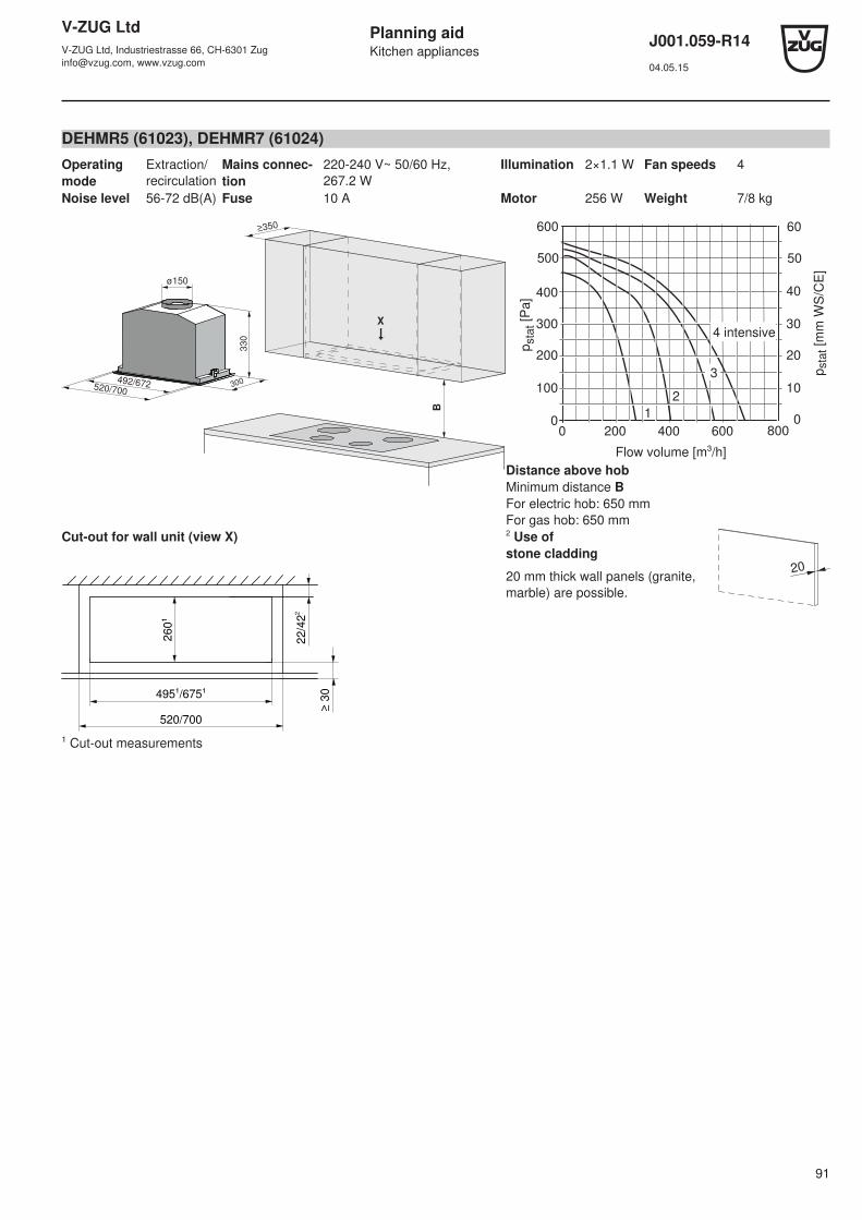
V-ZUG LtdV-ZUG Ltd, Industriestrasse 66, CH-6301 [email protected], www.vzug.com
Planning aidKitchen appliances
J001.059-R1404.05.15
91
DEHMR5 (61023), DEHMR7 (61024)Operatingmode
Extraction/recirculation
Mains connec-tion
220-240 V~ 50/60 Hz,267.2 W
Illumination 2×1.1 W Fan speeds 4
Noise level 56-72 dB(A) Fuse 10 A Motor 256 W Weight 7/8 kg
300
330
492/672
X
520/700
B
≥350
ø150
pst
at [
Pa]
100
200
300
400
0
Flow volume [m³/h]
200 400 6000
pst
at [
mm
WS
/CE
]
10
20
30
40
0
500 50
600 60
800
12
3
4 intensive
Distance above hobMinimum distance BFor electric hob: 650 mmFor gas hob: 650 mm
Cut-out for wall unit (view X)
520/700
495¹/675¹
260¹
22/4
22
≥ 3
0
2 Use ofstone cladding
20 mm thick wall panels (granite,marble) are possible.
20
¹ Cut-out measurements

V-ZUG LtdV-ZUG Ltd, Industriestrasse 66, CH-6301 [email protected], www.vzug.com
Planning aidKitchen appliances
J001.059-R1404.05.15
92
DEHMR8 (61025)Operatingmode
Extraction/recirculation
Mains connec-tion
220-240 V~ 50/60 Hz,267.2 W
Illumination 2×1.1 W Fan speeds 4
Noise level 56-72 dB(A) Fuse 10 A Motor 256 W Weight 9 kg
300
330
832
X
860
B
≥350
ø150
Flow volume [m³/h]
pst
at [
Pa
]
100
200
300
400
0200 400 6000
pst
at [
mm
WS
/CE
]
10
20
30
40
0
500 50
600 60
800
12
3
4 intensive
Distance above hobMinimum distance BFor electric hob: 650 mmFor gas hob: 650 mm
Cut-out for wall unit (view X)
860
835¹
260¹
22/4
22
≥ 3
0
2 Use ofstone cladding
20 mm thick wall panels (granite,marble) are possible.
20
¹ Cut-out measurements
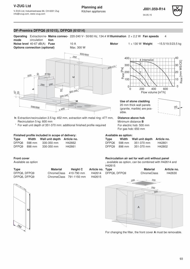
V-ZUG LtdV-ZUG Ltd, Industriestrasse 66, CH-6301 [email protected], www.vzug.com
Planning aidKitchen appliances
J001.059-R1404.05.15
93
DF-Premira DFPQ6 (61015), DFPQ9 (61014)Operatingmode
Extraction/re-circulation
Mains connec-tion
220-240 V~ 50/60 Hz, 134.4 W Illumination 2 × 2.2 W Fan speeds 4
Noise level 40-67 dB(A) Fuse 10 A Motor 1 × 130 W Weight ~15.5/19.5/23.5 kgOptions connection (optional) Max. 300 W
330-370 ¹
292
600/900
300-345 ¹
290290
300-345 ¹
598/898
200ø1503
0
495
55 5
5h
67
B
C pst
at [
Pa]
100
200
300
400
0
Flow volume [m³/h]200 400 6000
pst
at [
mm
WS
/CE
]
10
20
30
40
0
3
2
1
4 Intensive
Use of stone cladding20 mm thick wall panels(granite, marble) are pos-sible.
20
h: Extraction/recirculation 2.5 kg: 452 mm, extraction with metal ring: 477 mm, Recirculation 5 kg: 600 mm
Distance above hobMinimum distance BFor electric hob: 500 mmFor gas hob: 650 mm
¹ For wall unit depth of 351-370 mm: additional finished profile required
Finished profile included in scope of delivery: Available as option:Type Width Wall unit depth Article no. Type Width Wall unit depth Article no.DFPQ6 598 mm 330-350 mm H42662 DFPQ6 598 mm 351-370 mm H42801DFPQ9 898 mm 330-350 mm H42661 DFPQ9 898 mm 351-370 mm H42802
Front coverAvailable as option
Recirculation air set for wall unit without panel, available as option, can be combined with H42614 andH42615
Type Material Height C Article no. Type Material Article no.DFPQ6, DFPQ9 ChromeClass 410-790 mm H42614 DFPQ6, DFPQ9 ChromeClass H42630DFPQ6, DFPQ9 ChromeClass 791-1150 mm H42615
CC
292
300
292
330299
A
For changing the filter, the front cover A must be removable.

V-ZUG LtdV-ZUG Ltd, Industriestrasse 66, CH-6301 [email protected], www.vzug.com
Planning aidKitchen appliances
J001.059-R1404.05.15
94
DF-Premira DFPQ12 (61013)Operatingmode
Extraction/re-circulation
Mains connec-tion
220-240 V~ 50/60 Hz, 136.6 W Illumination 3 × 2.2 W Fan speeds 4
Noise level 40-67 dB(A) Fuse 10 A Motor 1 × 130 W Weight ~27.5 kgOptions connection (optional) Max. 300 W
330-370
292
1200
300-345¹
55
¹
¹
290290
300-345
1198
6755
200
h
ø15030
495
55
B
C pst
at [
Pa]
100
200
300
400
0
Flow volume [m³/h]200 400 6000
pst
at [
mm
WS
/CE
]
10
20
30
40
0
3
2
1
4 Intensive
Use of stone cladding
20 mm thick wall panels(granite, marble) are pos-sible.
20
h: Extraction/recirculation 2.5 kg: 452 mm, extraction with metal ring: 477 mm, Recirculation 5 kg: 600 mm
Distance above hobMinimum distance BFor electric hob: 500 mmFor gas hob: 650 mm
¹ For wall unit depth of 351-370 mm: additional finished profile required
Finished profile included in scope of delivery: Available as option:Type Width Wall unit depth Article no. Type Width Wall unit depth Article no.DFPQ12 1198 mm 330-350 mm H42660 DFPQ12 1198 mm 351-370 mm H42803
Front coverAvailable as option
Recirculation air set for wall unit without panel, available as option, can be combined with H42614 andH42615
Type Material Height C Article no. Type Material Article no.DFPQ12 ChromeClass 410-790 mm H42614 DFPQ12 ChromeClass H42630DFPQ12 ChromeClass 791-1150 mm H42615
CC
292
300
292
330299
A
For changing the filter, the front cover A must be removable.

V-ZUG LtdV-ZUG Ltd, Industriestrasse 66, CH-6301 [email protected], www.vzug.com
Planning aidKitchen appliances
J001.059-R1404.05.15
95
DF-Premira SL DFPQSL6 (61008), DFPQSL9 (61007)Operatingmode
Extraction/re-circulation
Mains connec-tion
220-240 V~ 50/60 Hz, 134.4 W Illumination 2 × 2.2 W Fan speeds 4
Noise level 40-67 dB(A) Fuse 10 A Motor 1 × 130 W Weight ~12.5/16.5 kgOptions connection (optional) Max. 300 W
330-370 ¹
292
600/900
300-345 ¹
290290
300-345 ¹
598/898
76
200ø1503
0
480
25
78
h
B
C
pst
at [
Pa]
100
200
300
400
0
Flow volume [m³/h]200 400 6000
pst
at [
mm
WS
/CE
]
10
20
30
40
0
2
1
4
3
Intensive
Use of stone cladding
20 mm thick wall panels(granite, marble) are pos-sible.
20
h: Extraction/recirculation 2.5 kg: 452 mm, extraction with metal ring: 490 mm, Recirculation 5 kg: 600 mm
Distance above hobMinimum distance BFor electric hob: 500 mmFor gas hob: 650 mm
¹ For wall unit depth of 351-370 mm: additional finished profile required
Finished profile included in scope of delivery: Available as option:Type Width Wall unit depth Type Width Wall unit depth Article no.DFPQSL6 598 mm 330-350 mm DFPQSL6 598 mm 351-370 mm H42805DFPQSL9 898 mm 330-350 mm DFPQSL9 898 mm 351-370 mm H42806
Front coverAvailable as option
Recirculation air set for wall unit without panel, available as option, can be combined with H42614 andH42615
Type Material Height C Article no. Type Material Article no.DFPQSL6/9 ChromeClass 410-790 mm H42614 DFPQSL5/6/9 ChromeClass H42630DFPQSL6/9 ChromeClass 791-1150 mm H42615
CC
292
300
292
A
330299
For changing the filter, the front cover A must be remov-able.
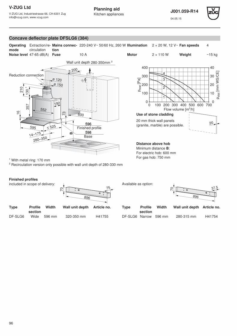
V-ZUG LtdV-ZUG Ltd, Industriestrasse 66, CH-6301 [email protected], www.vzug.com
Planning aidKitchen appliances
J001.059-R1404.05.15
96
Concave deflector plate DFSLG6 (384)Operatingmode
Extraction/re-circulation
Mains connec-tion
220-240 V~ 50/60 Hz, 260 W Illumination 2 × 20 W, 12 V~ Fan speeds 4
Noise level 47-65 dB(A) Fuse 10 A Motor 2 × 110 W Weight ~15 kg
≥ 200
192
130 ¹
357
16
≤ 525
280–350
73
600
595
552
14–175
210
B
ø 120ø 150
280-350mm ²
598Base
596
598
596
Reduction connection
Finished profile
Wall unit depth
¹ With metal ring: 170 mm² Recirculation version only possible with wall unit depth of 280-330 mm
1
4
400
300
200
100
0
40
30
20
10
00 100 200 300 400 500 600 700
pst
at [
mm
WS
/CE
]
pst
at [
Pa
]
3
2
Flow volume [m³/h]
Use of stone cladding
20 mm thick wall panels(granite, marble) are possible. 20
Distance above hobMinimum distance B:For electric hob: 600 mmFor gas hob: 750 mm
Finished profilesincluded in scope of delivery:
70 75
896
Available as option:
70 37.5
896
Type Profilesection
Width Wall unit depth Article no. Type Profilesection
Width Wall unit depth Article no.
DF-SLG6 Wide 596 mm 320-350 mm H41755 DF-SLG6 Narrow 596 mm 280-315 mm H41754
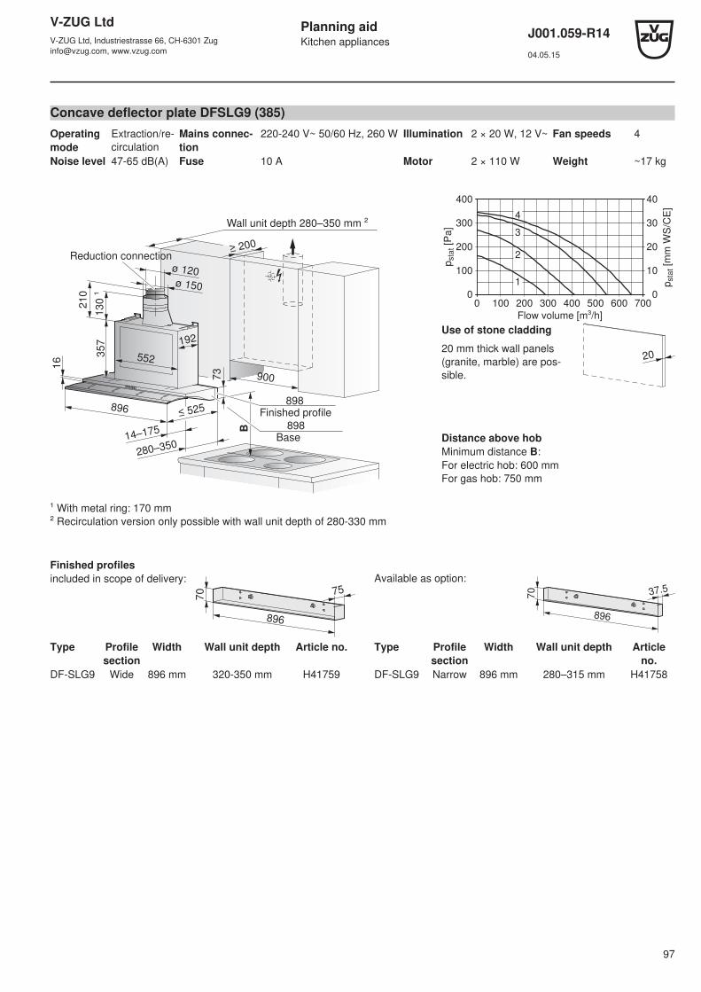
V-ZUG LtdV-ZUG Ltd, Industriestrasse 66, CH-6301 [email protected], www.vzug.com
Planning aidKitchen appliances
J001.059-R1404.05.15
97
Concave deflector plate DFSLG9 (385)Operatingmode
Extraction/re-circulation
Mains connec-tion
220-240 V~ 50/60 Hz, 260 W Illumination 2 × 20 W, 12 V~ Fan speeds 4
Noise level 47-65 dB(A) Fuse 10 A Motor 2 × 110 W Weight ~17 kg
130 ¹
357
16
73
B
900
552
192
≥ 200
≤ 525
280–350
896
14–175
210
ø 120ø 150
898Base
Reduction connection
898Finished profile
Wall unit depth 280–350 mm ²
¹ With metal ring: 170 mm² Recirculation version only possible with wall unit depth of 280-330 mm
1
4
400
300
200
100
0
40
30
20
10
00 100 200 300 400 500 600 700
pst
at [
mm
WS
/CE
]
pst
at [
Pa]
3
2
Flow volume [m³/h]
Use of stone cladding
20 mm thick wall panels(granite, marble) are pos-sible.
20
Distance above hobMinimum distance B:For electric hob: 600 mmFor gas hob: 750 mm
Finished profilesincluded in scope of delivery:
70 75
896
Available as option:
70 37.5
896
Type Profilesection
Width Wall unit depth Article no. Type Profilesection
Width Wall unit depth Articleno.
DF-SLG9 Wide 896 mm 320-350 mm H41759 DF-SLG9 Narrow 896 mm 280–315 mm H41758

V-ZUG LtdV-ZUG Ltd, Industriestrasse 66, CH-6301 [email protected], www.vzug.com
Planning aidKitchen appliances
J001.059-R1404.05.15
98
14 Refrigerators
14.1 General notes
Insufficient ventilation can cause a malfunction and shorten the life of the appliance.
Heavy door panel weights shorten the service life of the door hinges.
Efficient repairs can only be guaranteed if it is possible to uninstall the whole appliance at any time without causing anydamage.
In an open-plan kitchen and living room, a raised noise level can be expected if the ventilation slits face into the room.
14.2 Electrical connection data
Appliance Climate class Mains connection Fuse Mains cable
Refrigerators
Cooltronic 60i SN-ST 230 V~ 50 Hz 10 A 2.2 m, with plug
Noblesse 60i
Prestige P 60i ecoPrestige 60i eco
SN-T
De Luxe 60i eco
Futura 60i eco
Futura 60i SN-ST
Royal 60i
Prestige 60i
De Luxe 60i
Magnum 60i eco SN-T 230 V~ 50 Hz 2.5 m, with plug
Komfort 60i N-ST
Winecoolers
Winecooler SL 60 SN-ST 230 V~ 50 Hz 10 A 2.1 m, with plug
14.3 Ambient conditions
Condensate may form in the appliance in tropical conditions
and this has to be taken into account in the planning.
Climate class Minimum Maximum
SN +10 °C +32 °C
N +16 °C +32 °C
ST +16 °C +38 °C
T +16 °C +43 °C
Ventilation200 cm² above and below
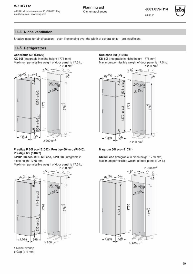
V-ZUG LtdV-ZUG Ltd, Industriestrasse 66, CH-6301 [email protected], www.vzug.com
Planning aidKitchen appliances
J001.059-R1404.05.15
99
14.4 Niche ventilation
Shadow gaps for air circulation – even if extending over the width of several units – are insufficient.
14.5 Refrigerators
Cooltronic 60i (51029) Noblesse 60i (51028)KC 60i (integrable in niche height 1778 mm)Maximum permissible weight of door panel is 17.5 kg
KN 60i (integrable in niche height 1778 mm)Maximum permissible weight of door panel is 17.5 kg
1270+
a-b/2
508+
a-b/2
a
≤ 594 545
54816–20
560–568
17781776
+2 0
a
≥ 550
≥ 200 cm²
≥ 200 cm²
≥ 50
1270+
a-b/2
508+
a-b/2
a
≤ 594 545
54816–20
560–568
1778
1776
+2 0
a
≥ 550
≥ 200 cm²
≥ 200 cm²
≥ 50
Prestige P 60i eco (51052), Prestige 60i eco (51045), Prestige 60i (51027)
Magnum 60i eco (51031)
KPRP 60i eco, KPR 60i eco, KPR 60i (integrable in niche height 1778 mm)Maximum permissible weight of door panel is 17.5 kg
KM 60i eco (integrable in niche height 1778 mm)Maximum permissible weight of door panel is 25 kg
1143+
a-b/2
635+
a-b/2
a
≤ 594 545
54816–20
560–568
1778
1776
+2 0
a
≥ 550
≥ 200 cm²
≥ 200 cm²
≥ 50
17
78+
2 0
≥ 550
≥ 200 cm²
≥ 200 cm²
≥ 50
17
78
+a
17
70
54816–20
≤ 594 545
560–568
a Niche overlapb Gap (≥ 4 mm)

V-ZUG LtdV-ZUG Ltd, Industriestrasse 66, CH-6301 [email protected], www.vzug.com
Planning aidKitchen appliances
J001.059-R1404.05.15
100
Futura 60i eco (51061), Futura 60i (51020) Royal 60i (51018)KF 60i eco, KF 60i (integrable in niche height 1524 mm)Maximum permissible weight of door panel is 17.5 kg
KR 60i (integrable in niche height 1524 mm)Maximum permissible weight of door panel is 17.5 kg
889+
a-b/2
635+
a-b/2
a
≤ 594 545
54816–20
560–568
15241522
+2 0
a
≥ 550
≥ 200 cm²
≥ 200 cm²
≥ 50
560–568
≥ 550
≥ 200 cm²
≥ 200 cm²
≥ 50
1522
1524+
a
54816–20
≤ 594 545
1524+2 0
De Luxe 60i eco (51060), De Luxe 60i (51064) Komfort 60i (51048)KL 60i eco, KL 60i (integrable in niche height 1524 mm)Maximum permissible weight of door panel is 17.5 kg
KK 60i (integrable in niche height 820–870 mm)Maximum permissible weight of door panel is 17.5 kg
560–568
≥ 550
≥ 200 cm²
≥ 200 cm²
≥ 50
1522
1524+
a
54816–20
≤ 594 545
1524+2 0
17
≥ 550
100–185
545
16–20
100–185
600
597
≥ 680
30–60
≥ 600
595
819–869
(≤ 889)
820–870
(≤ 890)
3
A
Ventilation partintegrated in plinth
Plinth must be recessed for ventilation purposes
Detail A
a Niche overlapb Gap (≥ 4 mm)
Installation set for stone cladding is enclosed: H72998

V-ZUG LtdV-ZUG Ltd, Industriestrasse 66, CH-6301 [email protected], www.vzug.com
Planning aidKitchen appliances
J001.059-R1404.05.15
101
14.6 Winecoolers
Winecooler SL 60 (629)KWSL60
594 566
873
547
886
≥ 200 cm²
560–568
≥ 550
≥ 200 cm²
≥ 50
H
874–889
X
Y
Detail X
S²
/ U
²
H1
Detail Y
H S¹
/ U
¹
1
Niche height H Installation kit art. no. Installation kit height Overlap
U1 U2
874-877 - - 6 mm 3-6 mm
877-880 H72435 3 mm 3 mm 3-6 mm

V-ZUG LtdV-ZUG Ltd, Industriestrasse 66, CH-6301 [email protected], www.vzug.com
Planning aidKitchen appliances
J001.059-R1404.05.15
102
15 Dishwashers
Dishwashers with heat pump ﴾see page 112﴿
15.1 General notes
Efficient repairs can only be guaranteed if it is possible to uninstall the whole appliance at any time without causing anydamage.
At any time it must be possible to pull the appliance out of the niche horizontally without dismantling any part of the cabinet.
For work surfaces that are susceptible to moisture, use work surface protection W70163.
General operating conditionsAmbient temperature: from min. 10 °C to max. 35 °C
The appliances are designed for use up to a max. altitude of 2000 m above sea level.
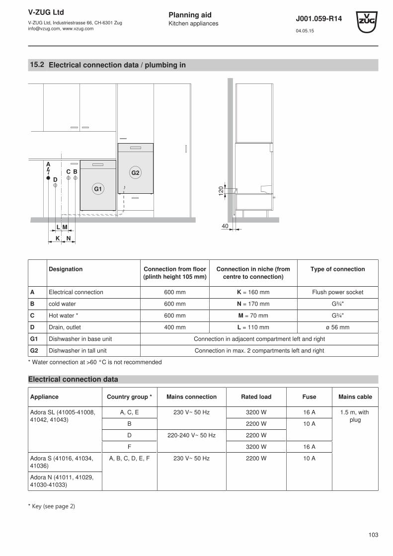
V-ZUG LtdV-ZUG Ltd, Industriestrasse 66, CH-6301 [email protected], www.vzug.com
Planning aidKitchen appliances
J001.059-R1404.05.15
103
15.2 Electrical connection data / plumbing in
40
12
0
K
L M
N
G1
G2
D
C B
A
Designation Connection from floor(plinth height 105 mm)
Connection in niche (fromcentre to connection)
Type of connection
A Electrical connection 600 mm K = 160 mm Flush power socket
B cold water 600 mm N = 170 mm G¾"
C Hot water * 600 mm M = 70 mm G¾"
D Drain, outlet 400 mm L = 110 mm ø 56 mm
G1 Dishwasher in base unit Connection in adjacent compartment left and right
G2 Dishwasher in tall unit Connection in max. 2 compartments left and right
* Water connection at >60 °C is not recommended
Electrical connection data
Appliance Country group * Mains connection Rated load Fuse Mains cable
Adora SL (41005-41008, 41042, 41043)
A, C, E 230 V~ 50 Hz 3200 W 16 A 1.5 m, with plug
B 2200 W 10 A
D 220-240 V~ 50 Hz 2200 W
F 3200 W 16 A
Adora S (41016, 41034, 41036)
A, B, C, D, E, F 230 V~ 50 Hz 2200 W 10 A
Adora N (41011, 41029, 41030-41033)
* Key ﴾see page 2﴿

V-ZUG LtdV-ZUG Ltd, Industriestrasse 66, CH-6301 [email protected], www.vzug.com
Planning aidKitchen appliances
J001.059-R1404.05.15
104
Plumbing-in data
For special cases with water hardness in excess of 50 °fH, an external water softener is recommended.
Value Nominal value Minimum Maximum
Mains pressure (0.1 MPa = 1 bar) Static 0.3–0.4 MPa 0.1 MPa 1.0 MPa
Flowing – 0.08 MPa 1.0 MPa
Water hardness – 0.5 °fH 50 °fH
Water inlet temperature Cold water – 5 °C 35 °C
Hot water – 40 °C 60 °C
If the water pressure is too high, a pressure reducer valve must be fitted.
Connection example
A1
F
E, C
E, B
D
A2
Designation Adora dishwasher
A1 Power socket Yes
A2 Connection cable Length 1.50 m
B Cold water connection Yes
C Hot water connection Yes
D Drain hose Length 1.55 mInternal diameter = 22 mm
E Shut-off devices Yes
F Aqua-stop / water inlet with filter, G¾" Length 1.55 m
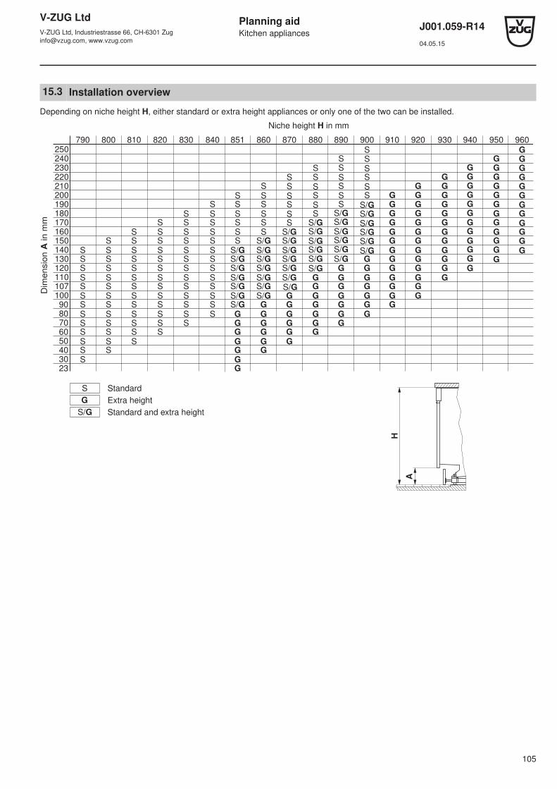
V-ZUG LtdV-ZUG Ltd, Industriestrasse 66, CH-6301 [email protected], www.vzug.com
Planning aidKitchen appliances
J001.059-R1404.05.15
105
15.3 Installation overview
Depending on niche height H, either standard or extra height appliances or only one of the two can be installed.
790 800 810 820 830 840 851 860 870 880 890 900 910 920 930 940 950 960
220230240250
S G
210 S S G G
200 S S S G G G
190 S S S S G G G
180 S S S S S G G G
170 S S S S S S
SSSSSS
SSSSSS
SSSSSS
G G G
160 S S S S S S S/G G G G
150 S S S S S S S/G G G G
140 S S S S S S S/G S/G G G G
130 S S S S S S S/G S/G G G G G
120 S S S S S S S/G S/G G G G G G
110 S S S S S S S/G S/G
S/GS/GS/GS/GS/GS/G
S/GS/GS/GS/GS/GS/G
S/GS/GS/GS/GS/GS/G
G G G G G G
107 S S S S S S S/G G G G G G
100 S S S S S S S/G S/G G G G G G G
G
G
G
G
G
G
G
G
G
G
G
G
G
G
G
G
G
G
G
G
G
G
G
G
G
G
G
G
G
G
G
G
G
G
G
G
90 S S S S S S S/G G G G G G G
80 S S S S S S G G G G G G
70 S S S S S G G G G G
60 S S S S G G G G
50 S S S G G G
40 S S G G
30 S G
23 G
S
G
S/G
S/GS/GS/GS/GS/GS/G S/GD
imensio
n A
in m
m
Standard
Extra height
Standard and extra height
Niche height H in mm
H
A
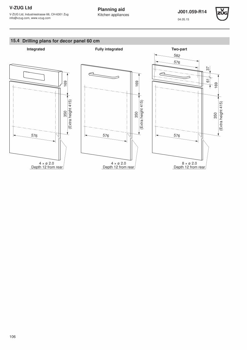
V-ZUG LtdV-ZUG Ltd, Industriestrasse 66, CH-6301 [email protected], www.vzug.com
Planning aidKitchen appliances
J001.059-R1404.05.15
106
15.4 Drilling plans for decor panel 60 cm
61
37
169
169
169
576576576
576
582
4 × ø 2.0Depth 12 from rear
8 × ø 2.0Depth 12 from rear
4 × ø 2.0
Integrated Fully integrated Two-part
Depth 12 from rear
(Extr
a h
eig
ht 415)
350
(Extr
a h
eig
ht 415)
(Extr
a h
eig
ht 415)
350
350
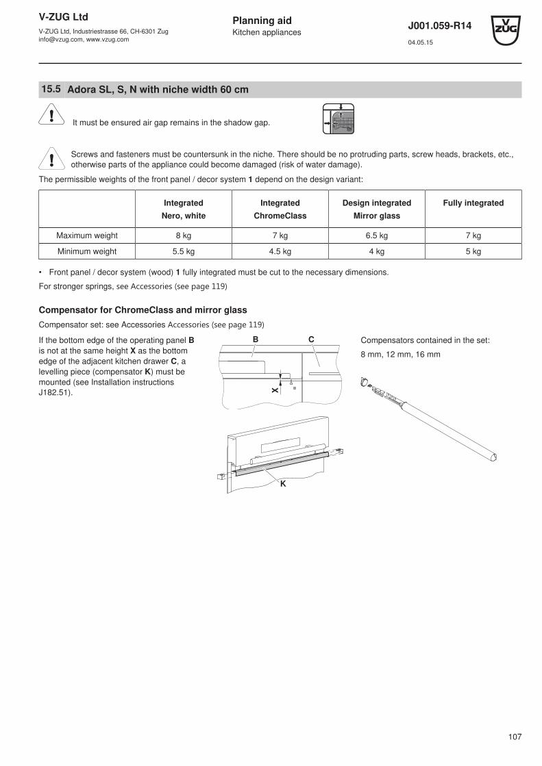
V-ZUG LtdV-ZUG Ltd, Industriestrasse 66, CH-6301 [email protected], www.vzug.com
Planning aidKitchen appliances
J001.059-R1404.05.15
107
15.5 Adora SL, S, N with niche width 60 cm
It must be ensured air gap remains in the shadow gap.
Screws and fasteners must be countersunk in the niche. There should be no protruding parts, screw heads, brackets, etc.,otherwise parts of the appliance could become damaged (risk of water damage).
The permissible weights of the front panel / decor system 1 depend on the design variant:
IntegratedNero, white
IntegratedChromeClass
Design integratedMirror glass
Fully integrated
Maximum weight 8 kg 7 kg 6.5 kg 7 kg
Minimum weight 5.5 kg 4.5 kg 4 kg 5 kg
• Front panel / decor system (wood) 1 fully integrated must be cut to the necessary dimensions.
For stronger springs, see Accessories ﴾see page 119﴿
Compensator for ChromeClass and mirror glassCompensator set: see Accessories Accessories ﴾see page 119﴿
If the bottom edge of the operating panel Bis not at the same height X as the bottomedge of the adjacent kitchen drawer C, alevelling piece (compensator K) must bemounted (see Installation instructionsJ182.51). X
B C
K
Compensators contained in the set:
8 mm, 12 mm, 16 mm

V-ZUG LtdV-ZUG Ltd, Industriestrasse 66, CH-6301 [email protected], www.vzug.com
Planning aidKitchen appliances
J001.059-R1404.05.15
108
Base unit «standard»
78
6–
86
7 *
*
21
–2
26
78
0–
86
1 *
30–100
63
9–
75
7
1
596 572
585
600
16–22
≥ 580BD
* Up to max. 896 with a second runner only,can be ordered under W82930
** Up to max. 902 with a second runner only,can be ordered under W82930
Nero, white ChromeClass Mirror glass
Operating panel B incl. compensator 124-146 mm 124-140 mm 124-140 mm
Decor panel D 490-632 mm 496-632 mm 496-632 mm
Size of base gap S.
790 800 810 820 830 840 850 860 870
107107 117
107 117 127117 127 137127 137 147137 147 155
47 57 67 778797
145 155 165
22222222510152330
37 47 57 67 778797
27 37 47 57 67 778797
Min.
Max.
127127 137
107117
127 137 147127 137 147
97107117
157127 137 147 157 167
127 137 147 157
87 97107117
167 177137 147 157 167 177 187147 157 167
77 87 97107117
177 187 197157 167 177 187 197 207167 177
67 77 87 97107117
187 197 207 217175 185 195 205 215 225
880
137147
117127
157167177187197207217227235
890
147157
127137
167177187197207217227237245
900
157167
137147
177187197207217227237247255
57 67 77 87 97107117
Niche height H in mm Min. Sin mm
Dim
en
sio
n A
in
mm H
30–100
A
S
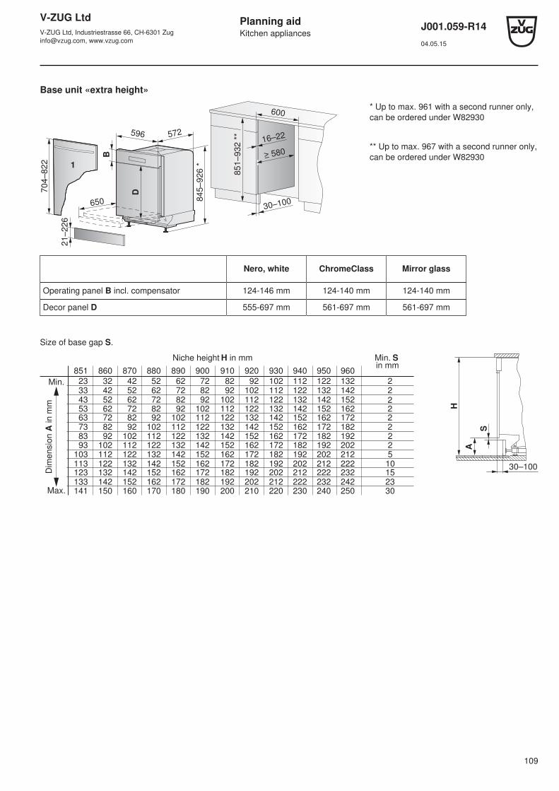
V-ZUG LtdV-ZUG Ltd, Industriestrasse 66, CH-6301 [email protected], www.vzug.com
Planning aidKitchen appliances
J001.059-R1404.05.15
109
Base unit «extra height»
85
1–
93
2 *
*
21
–2
26
84
5–
92
6 *
30–100
70
4–
82
2
1
596 572
650
600
16–22
≥ 580B
D
* Up to max. 961 with a second runner only,can be ordered under W82930
** Up to max. 967 with a second runner only,can be ordered under W82930
Nero, white ChromeClass Mirror glass
Operating panel B incl. compensator 124-146 mm 124-140 mm 124-140 mm
Decor panel D 555-697 mm 561-697 mm 561-697 mm
Size of base gap S.
851 860 870 880 890 900 910 920 930
102102 112
103 112 122113 122 132123 132 142133 142 152
42 52 62 728292
141 150 160
22222222510152330
32 42 52 62 728292
23 33 43 53 63 738393
Min.
Max.
122122 132
102112
122 132 142122 132 142
92102112
152122 132 142 152 162
122 132 142 152
82 92102112
162 172132 142 152 162 172 182142 152 162
72 82 92102112
172 182 192152 162 172 182 192 202162 172
62 72 82 92102112
182 192 202 212170 180 190 200 210 220
940
132142
112122
152162172182192202212222230
950
142152
122132
162172182192202212222232240
960
152162
132142
172182192202212222232242250
52 62 72 82 92102112
Niche height H in mm Min. Sin mm
Dim
ensio
n A
in m
m H
30–100A
S

V-ZUG LtdV-ZUG Ltd, Industriestrasse 66, CH-6301 [email protected], www.vzug.com
Planning aidKitchen appliances
J001.059-R1404.05.15
110
Tall unit «standard»
Can also be installed in base unit on base element
Tall unit «extra height»
D
75
6
75
7
76
4
+1
-2
10
5
596 572
600
501
585
B
3 m
m
C
C Slide plate
12
0
40
D
82
1
82
2
82
9
+1
-2
10
5
596 572
600
501
650
B
3 m
m
C
«Standard» Nero, white ChromeClass Mirror glass
Operating panel B incl. compensator 124-146 mm 124-140 mm 124-140 mm
Decor panel D 610-632 mm 616-632 mm 616-632 mm
«Extra height» Nero, white ChromeClass Mirror glass
Operating panel B incl. compensator 124-146 mm 124-140 mm 124-140 mm
Decor panel D 675-697 mm 681-697 mm 681-697 mm
Slide plate conversion set for tall unit must be ordered from V-ZUG, see Accessories ﴾see page 135﴿.

V-ZUG LtdV-ZUG Ltd, Industriestrasse 66, CH-6301 [email protected], www.vzug.com
Planning aidKitchen appliances
J001.059-R1404.05.15
111
Tall unit «extra height» with decor panel and drawer 251 mm
Slide plate conversion set for tall unit must be ordered from V-ZUG, see Accessories ﴾see page 135﴿.
596 5721
87
600
50
25
1
829
+1
-2
821
10
5
650
D
B
75
7
1
12
0
40
3 m
m
C
C Slide plate
E Removable cover strip
Cross-section of installation variant
60
25
11
,5
10
16
(8
/6)
40
D
10
5
E
Nero, white ChromeClass Mirror glass
Operating panel B incl. compensator 124-146 mm 124-140 mm 124-140 mm
Decor panel D 610-632 mm 616-632 mm 616-632 mm
Installing extra-long decor panel
≥ 100*
H
6
5E
F
G
6
* A continuous soffit vent is recommended.
E Worktop
F Continuous soffit vent
G Decoration
H Niche height
V-ZUG LtdV-ZUG Ltd, Industriestrasse 66, CH-6301 [email protected], www.vzug.com
Planning aidKitchen appliances
J001.059-R1404.05.15
112
16 Dishwashers with heat pump
16.1 General notes
Efficient repairs can only be guaranteed if it is possible to uninstall the whole appliance at any time without causing anydamage.
At any time it must be possible to pull the appliance out of the niche horizontally without dismantling any part of the cabinet.
For work surfaces that are susceptible to moisture, use work surface protection W70163.
General operating conditionsAmbient temperature: from min. 10 °C to max. 35 °C
The appliances are designed for use up to a max. altitude of 2000 m above sea level.

V-ZUG LtdV-ZUG Ltd, Industriestrasse 66, CH-6301 [email protected], www.vzug.com
Planning aidKitchen appliances
J001.059-R1404.05.15
113
16.2 Electrical connection data / plumbing in
40
12
0
K
L M
N
G1
G2
D
C B
A
Designation Connection from floor(plinth height 105 mm)
Connection in niche (fromcentre to connection)
Type of connection
A Electrical connection 600 mm K = 160 mm Flush power socket
B cold water 600 mm N = 170 mm G¾"
C Hot water * 600 mm M = 70 mm G¾"
D Drain, outlet 400 mm L = 110 mm ø 56 mm
G1 Dishwasher in base unit Connection in adjacent compartment left and right
G2 Dishwasher in tall unit Connection in max. 2 compartments left and right
* Water connection at >60 °C is not recommended
Electrical connection data
Appliance Country group * Mains connection Rated load Fuse Mains cable
Adora SL WP (41009, 41038)
A, C, E 230 V~ 50 Hz 3200 W 16 A 1.5 m, with plug
B 2200 W 10 A
D 220-240 V~ 50 Hz 2200 W
F 3200 W 16 A
* Key ﴾see page 2﴿

V-ZUG LtdV-ZUG Ltd, Industriestrasse 66, CH-6301 [email protected], www.vzug.com
Planning aidKitchen appliances
J001.059-R1404.05.15
114
Plumbing-in data
For special cases with water hardness in excess of 50 °fH, an external water softener is recommended.
Value Nominal value Minimum Maximum
Mains pressure (0.1 MPa = 1 bar) Static 0.3–0.4 MPa 0.1 MPa 1.0 MPa
Flowing – 0.08 MPa 1.0 MPa
Water hardness – 0.5 °fH 50 °fH
Water inlet temperature – 5 °C 60 °C
Connection example
A1
F
E, C
E, B
D
A2
Designation Adora dishwasher
A1 Power socket Yes
A2 Connection cable Length 1.50 m
B Cold water connection Yes
C Hot water connection Yes
D Drain hose Length 1.55 mInternal diameter = 22 mm
E Shut-off devices Yes, ¾"
F Aqua-stop / water inlet with filter, G¾" Length 1.55 m
See Accessories ﴾see page 135﴿ for special connection lengths.
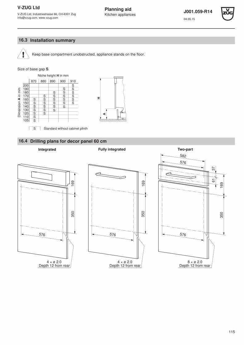
V-ZUG LtdV-ZUG Ltd, Industriestrasse 66, CH-6301 [email protected], www.vzug.com
Planning aidKitchen appliances
J001.059-R1404.05.15
115
16.3 Installation summary
Keep base compartment unobstructed, appliance stands on the floor.
Size of base gap S.
870 880 890 900 910
200190180170160150140130120110105
S
SSSSSS
SSSSSS
SSSSSS
SSSSSS
SSSSSS
S
Standard without cabinet plinth
H
A
Niche height H in mm
Dim
en
sio
n A
in
mm
16.4 Drilling plans for decor panel 60 cm
61
37
16
9
16
9
16
9
576576576
576
582
4 × ø 2.0 8 × ø 2.0
4 × ø 2.0
35
0
35
0
35
0
Depth 12 from rear Depth 12 from rear Depth 12 from rear
Integrated Fully integrated Two-part
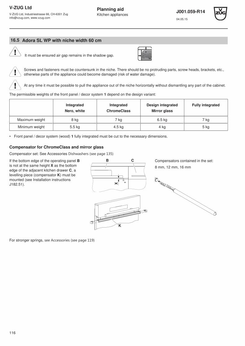
V-ZUG LtdV-ZUG Ltd, Industriestrasse 66, CH-6301 [email protected], www.vzug.com
Planning aidKitchen appliances
J001.059-R1404.05.15
116
16.5 Adora SL WP with niche width 60 cm
It must be ensured air gap remains in the shadow gap.
Screws and fasteners must be countersunk in the niche. There should be no protruding parts, screw heads, brackets, etc.,otherwise parts of the appliance could become damaged (risk of water damage).
At any time it must be possible to pull the appliance out of the niche horizontally without dismantling any part of the cabinet.
The permissible weights of the front panel / decor system 1 depend on the design variant:
IntegratedNero, white
IntegratedChromeClass
Design integratedMirror glass
Fully integrated
Maximum weight 8 kg 7 kg 6.5 kg 7 kg
Minimum weight 5.5 kg 4.5 kg 4 kg 5 kg
• Front panel / decor system (wood) 1 fully integrated must be cut to the necessary dimensions.
Compensator for ChromeClass and mirror glassCompensator set: See Accessories Dishwashers ﴾see page 135﴿
If the bottom edge of the operating panel Bis not at the same height X as the bottomedge of the adjacent kitchen drawer C, alevelling piece (compensator K) must bemounted (see Installation instructionsJ182.51). X
B C
K
Compensators contained in the set:
8 mm, 12 mm, 16 mm
For stronger springs, see Accessories ﴾see page 119﴿

V-ZUG LtdV-ZUG Ltd, Industriestrasse 66, CH-6301 [email protected], www.vzug.com
Planning aidKitchen appliances
J001.059-R1404.05.15
117
Base element
87
0–
91
0 *
10
5–
26
5
86
7–
90
7
30–100
63
9–
75
7
1
596 572
585
600
16–22
≥ 580BD
* If the niche height is greater than 910 mm,a plate must be placed underneath the appli-ance or an extra-long decor panel must beused.
Mirror glass Fully integrated
Operating panel B incl. compensator 124-140 mm -
Decor panel D 496-632 mm 639-757
Size of base gap S.
870
22222222510152330
Min.
Max.
127137
107117
147157167177187197207217225
880
137147
117127
157167177187197207217227235
890
147157
127137
167177187197207217227237245
900
157167
137147
177187197207217227237247255
910
167177
147157
187197207217227237247257265
Min. Sin mm
Niche height H in mm
Dim
en
sio
n A
in
mm
H
30–100
A
S

V-ZUG LtdV-ZUG Ltd, Industriestrasse 66, CH-6301 [email protected], www.vzug.com
Planning aidKitchen appliances
J001.059-R1404.05.15
118
Tall unit
A
D
867
757
870
≤
381
+1
-2
105
596 572
600
≥ 580
1
585
B
120
40
Cross-sectionInstallation example
1,5
10
16
(8
/6)
40
D
10
5
C
19
12
7
3
C Removable lower front panel (251)
Niche floor A
G
• Load-bearing capacity of niche floorA: 100 kg
• Given a load of 75 kg per appliance foot G , the niche floor may sag by a max. of 1 mm.
Mirror glass
Operating panel B incl. compensator 124-140 mm
Decor panel D 616-632 mm
Installing extra-long decor panel
≥ 100*
H
6
5E
F
G
6
* A continuous soffit vent is recommended.
E Worktop
F Continuous soffit vent
G Decoration
H Niche height
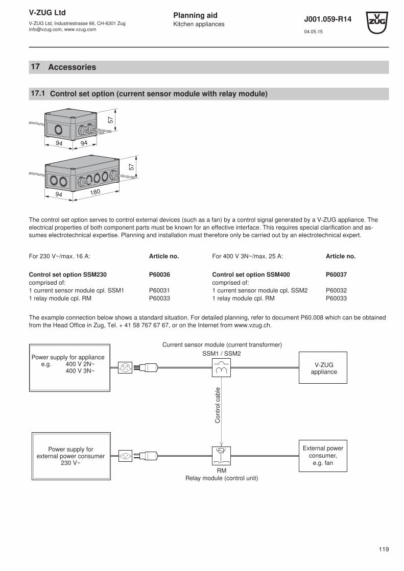
V-ZUG LtdV-ZUG Ltd, Industriestrasse 66, CH-6301 [email protected], www.vzug.com
Planning aidKitchen appliances
J001.059-R1404.05.15
119
17 Accessories
17.1 Control set option (current sensor module with relay module)
57
57
94 94
94 180
The control set option serves to control external devices (such as a fan) by a control signal generated by a V-ZUG appliance. Theelectrical properties of both component parts must be known for an effective interface. This requires special clarification and as-sumes electrotechnical expertise. Planning and installation must therefore only be carried out by an electrotechnical expert.
For 230 V~/max. 16 A: Article no. For 400 V 3N~/max. 25 A: Article no.
Control set option SSM230 P60036 Control set option SSM400 P60037comprised of: comprised of:1 current sensor module cpl. SSM1 P60031 1 current sensor module cpl. SSM2 P600321 relay module cpl. RM P60033 1 relay module cpl. RM P60033
The example connection below shows a standard situation. For detailed planning, refer to document P60.008 which can be obtainedfrom the Head Office in Zug, Tel. + 41 58 767 67 67, or on the Internet from www.vzug.ch.
SSM1 / SSM2
RM
Power supply for appliancee.g. 400 V 2N~ 400 V 3N~
Power supply forexternal power consumer
230 V~
External power
consumer,
e.g. fan
Current sensor module (current transformer)
Relay module (control unit)
V-ZUGappliance
Co
ntr
ol ca
ble

V-ZUG LtdV-ZUG Ltd, Industriestrasse 66, CH-6301 [email protected], www.vzug.com
Planning aidKitchen appliances
J001.059-R1404.05.15
120
17.2 Cookers / ovens / steam cookers / microwaves / coffee machines / warming & systemsdrawers
Compensation elements
Ventilation grille
• Ventilation grilles are needed when glass ceramic hobs are installed over ovens.
• For installation, see installation instructions J402.54.
Niche width 60 cmInstallation above the control panel
35
597 Construction types EURO60-600Short oven without drawer
Art. no.H63161 (white)H63163 (nero)H63165 (ChromeClass)
Adapter frame
• For installation, see installation instructions J731.050.
Niche width 60 cm
Installation below the applianceConstruction types EURO
48019.53
5
596
60-600Short ovenwithout drawer
60-381Mini oven
Art. no.K38137 (white)K38136 (nero)K48135 (ChromeClass)K38134 (glass)K38133 (AluClass)
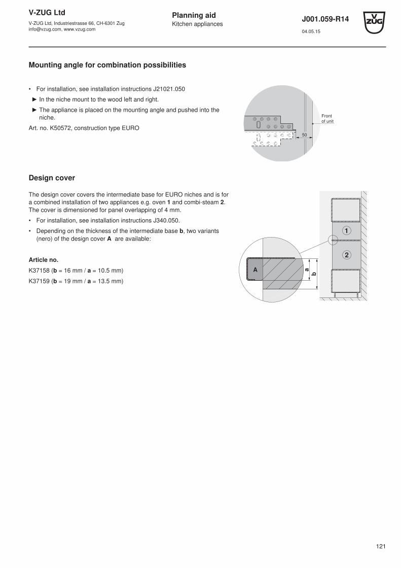
V-ZUG LtdV-ZUG Ltd, Industriestrasse 66, CH-6301 [email protected], www.vzug.com
Planning aidKitchen appliances
J001.059-R1404.05.15
121
Mounting angle for combination possibilities
• For installation, see installation instructions J21021.050
► In the niche mount to the wood left and right.
► The appliance is placed on the mounting angle and pushed into theniche.
Art. no. K50572, construction type EURO50
Front
of unit
Design cover
The design cover covers the intermediate base for EURO niches and is fora combined installation of two appliances e.g. oven 1 and combi-steam 2.The cover is dimensioned for panel overlapping of 4 mm.
• For installation, see installation instructions J340.050.
• Depending on the thickness of the intermediate base b, two variants(nero) of the design cover A are available:
Article no.
K37158 (b = 16 mm / a = 10.5 mm)
K37159 (b = 19 mm / a = 13.5 mm)
b
aA
1
2
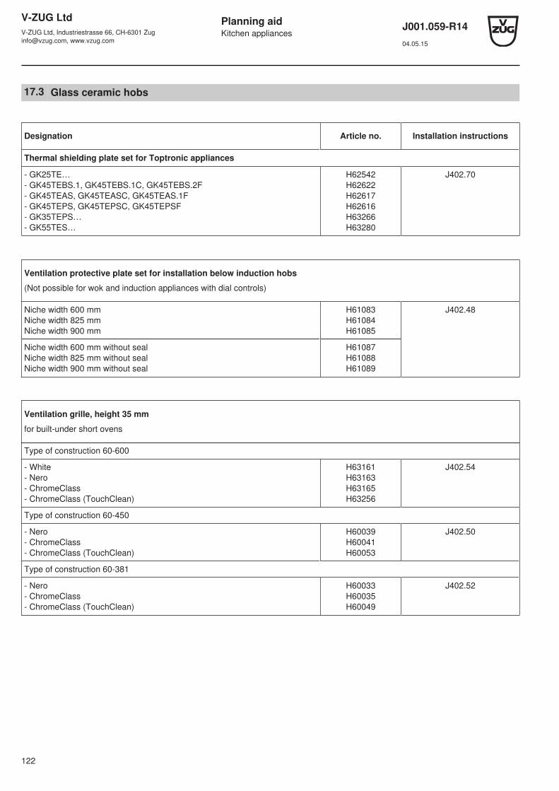
V-ZUG LtdV-ZUG Ltd, Industriestrasse 66, CH-6301 [email protected], www.vzug.com
Planning aidKitchen appliances
J001.059-R1404.05.15
122
17.3 Glass ceramic hobs
Designation Article no. Installation instructions
Thermal shielding plate set for Toptronic appliances
- GK25TE…- GK45TEBS.1, GK45TEBS.1C, GK45TEBS.2F- GK45TEAS, GK45TEASC, GK45TEAS.1F- GK45TEPS, GK45TEPSC, GK45TEPSF- GK35TEPS…- GK55TES…
H62542H62622H62617H62616H63266H63280
J402.70
Ventilation protective plate set for installation below induction hobs
(Not possible for wok and induction appliances with dial controls)
Niche width 600 mmNiche width 825 mmNiche width 900 mm
H61083H61084H61085
J402.48
Niche width 600 mm without sealNiche width 825 mm without sealNiche width 900 mm without seal
H61087H61088H61089
Ventilation grille, height 35 mm
for built-under short ovens
Type of construction 60-600
- White- Nero- ChromeClass- ChromeClass (TouchClean)
H63161H63163H63165H63256
J402.54
Type of construction 60-450
- Nero- ChromeClass- ChromeClass (TouchClean)
H60039H60041H60053
J402.50
Type of construction 60-381
- Nero- ChromeClass- ChromeClass (TouchClean)
H60033H60035H60049
J402.52

V-ZUG LtdV-ZUG Ltd, Industriestrasse 66, CH-6301 [email protected], www.vzug.com
Planning aidKitchen appliances
J001.059-R1404.05.15
123
Designation Article no. Installation instructions
Angle set for flush mounted installation with straight stone cut
- Hob size 30- Hob size 40- Hob size 60- Hob size 70- Hob size 80- Hob size 90- Hob size 80 Panorama- Hob size 90 Panorama
H63770H63771H63772H63773H63774H63775H62679H62568
–
Appropriate adhesive for mounting in stone worktops: Permabond F246, incl. activator, 50 ml tube. From Silitech AG, 3008 Bern.
B11502
Set for flush installation
Sealing strip set H63283 J004.130
Spacer kit H60330
Adjusting brace set for mounting in glass worktops
Adjusting brace set H62510 J416.99
Intermediate support sets for combined installation
Intermediate support set for gas (1×) H64140
Intermediate support set for induction (2×) H63789
Mastic set for flush installation
Mastic set 86392885 J004.130
Suitable for all absorbent worktop materials (wood and natural stones such as marble, granite).
The set comprises:
Designation Remarks Number
Cleaning agent, type T * – 1
Special primer, type 1105 * 100 ml bottle 1
Silicon adhesive, black cartridge with nozzle 1
For the remaining or for non-absorbent worktop materials and artificial stone surfaces, the special primer type 107 *, article no.45.2771.76, must be used. Not suitable for polyethylene, polypropylene or Teflon.
* Primer types: Firm name H. OTTO GmbH u. Co., Chemie GK, D-83413 Fridolfing
Good adhesion cannot be obtained on slate or other materials containing oil. The use of such worktop materials is not advised for theflush installation of glass ceramic hobs.
In case of doubt as to the suitability of mastic set materials, especially when using them for the first time, we recommendthat you carry out adhesion trials on test pieces or at non-visible locations.
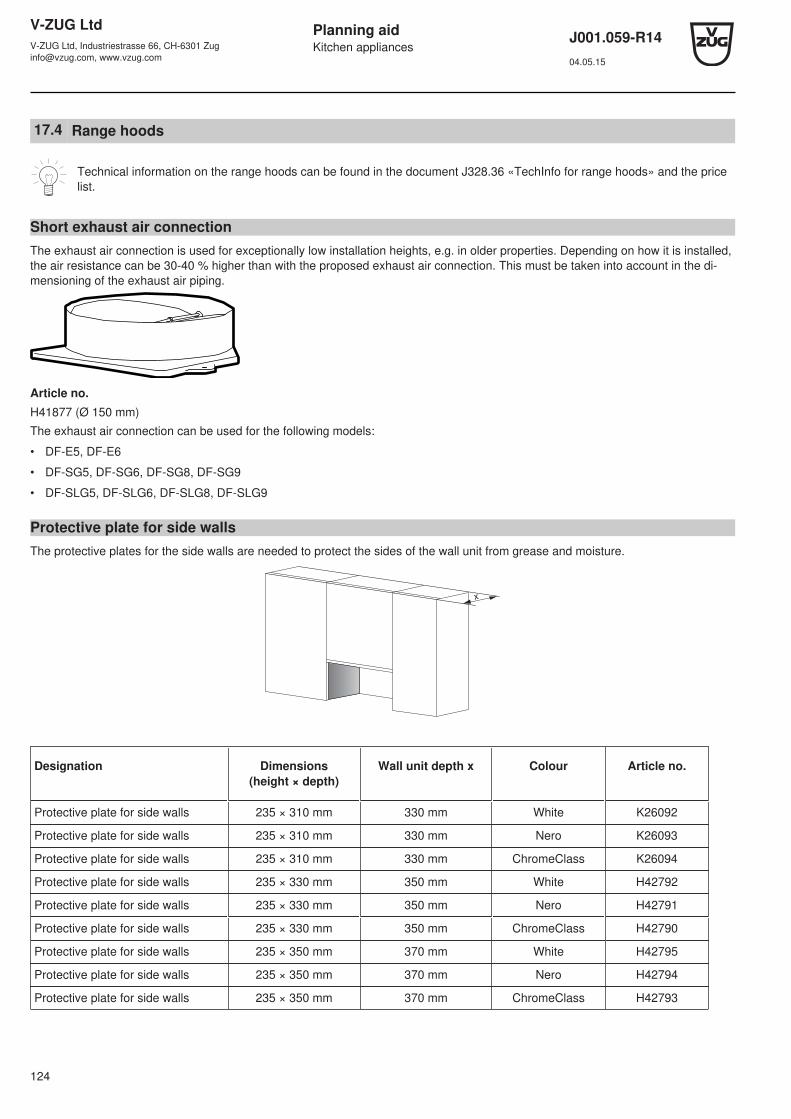
V-ZUG LtdV-ZUG Ltd, Industriestrasse 66, CH-6301 [email protected], www.vzug.com
Planning aidKitchen appliances
J001.059-R1404.05.15
124
17.4 Range hoods
Technical information on the range hoods can be found in the document J328.36 «TechInfo for range hoods» and the pricelist.
Short exhaust air connectionThe exhaust air connection is used for exceptionally low installation heights, e.g. in older properties. Depending on how it is installed,the air resistance can be 30-40 % higher than with the proposed exhaust air connection. This must be taken into account in the di-mensioning of the exhaust air piping.
Article no.H41877 (Ø 150 mm)
The exhaust air connection can be used for the following models:
• DF-E5, DF-E6
• DF-SG5, DF-SG6, DF-SG8, DF-SG9
• DF-SLG5, DF-SLG6, DF-SLG8, DF-SLG9
Protective plate for side wallsThe protective plates for the side walls are needed to protect the sides of the wall unit from grease and moisture.
x
Designation Dimensions(height × depth)
Wall unit depth x Colour Article no.
Protective plate for side walls 235 × 310 mm 330 mm White K26092
Protective plate for side walls 235 × 310 mm 330 mm Nero K26093
Protective plate for side walls 235 × 310 mm 330 mm ChromeClass K26094
Protective plate for side walls 235 × 330 mm 350 mm White H42792
Protective plate for side walls 235 × 330 mm 350 mm Nero H42791
Protective plate for side walls 235 × 330 mm 350 mm ChromeClass H42790
Protective plate for side walls 235 × 350 mm 370 mm White H42795
Protective plate for side walls 235 × 350 mm 370 mm Nero H42794
Protective plate for side walls 235 × 350 mm 370 mm ChromeClass H42793
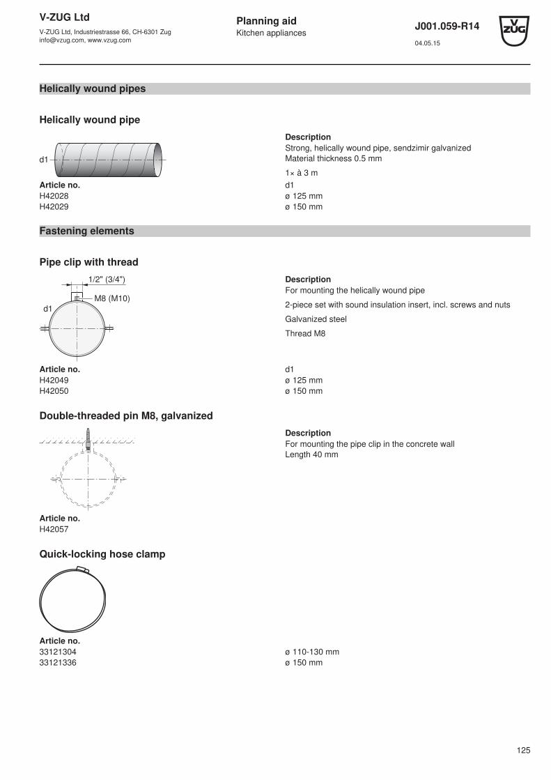
V-ZUG LtdV-ZUG Ltd, Industriestrasse 66, CH-6301 [email protected], www.vzug.com
Planning aidKitchen appliances
J001.059-R1404.05.15
125
Helically wound pipes
Helically wound pipe
Description
d1
Strong, helically wound pipe, sendzimir galvanizedMaterial thickness 0.5 mm
1× à 3 mArticle no. d1H42028 ø 125 mmH42029 ø 150 mm
Fastening elements
Pipe clip with thread
M8 (M10)
d1
1/2" (3/4") DescriptionFor mounting the helically wound pipe
2-piece set with sound insulation insert, incl. screws and nuts
Galvanized steel
Thread M8
Article no. d1H42049 ø 125 mmH42050 ø 150 mm
Double-threaded pin M8, galvanized
DescriptionFor mounting the pipe clip in the concrete wallLength 40 mm
Article no.H42057
Quick-locking hose clamp
Article no.33121304 ø 110-130 mm33121336 ø 150 mm

V-ZUG LtdV-ZUG Ltd, Industriestrasse 66, CH-6301 [email protected], www.vzug.com
Planning aidKitchen appliances
J001.059-R1404.05.15
126
Connecting nipples / connecting pipes
Connecting nipple
d1
L
DescriptionSendzimir galvanized sheet steel
L = 80 mm
Article no. d1H42030 ø 125 mmH42031 ø 150 mmH40169 ø 160 mm
Connecting pipe
d1
L
DescriptionSendzimir galvanized sheet steel
L = 90 mm
Article no. d1H42032 ø 125 mmH412033 ø 150 mm
Cladding elbow
Cladding elbow
d140
d1
45
Formwork
DescriptionFor installation on formwork
Specially for inlays in concrete ceiling
Sendzimir galvanized sheet steel
Article no. d1H42038 ø 125 mmH42039 ø 150 mm

V-ZUG LtdV-ZUG Ltd, Industriestrasse 66, CH-6301 [email protected], www.vzug.com
Planning aidKitchen appliances
J001.059-R1404.05.15
127
Elbows
Elbow 90°
R
d1
DescriptionElbow, pressed
Use with flexible and rigid pipes
Sendzimir galvanized sheet steel
R = d1
Article no. d1H42034 ø 125 mmH42036 ø 150 mm
Elbow 45°
R
d1 DescriptionElbow, pressed
Use with flexible and rigid pipes
Sendzimir galvanized sheet steel
R = d1
Article no. d1H42035 ø 125 mmH42037 ø 150 mm
Reducers
Reducer
d1 d2
L
DescriptionPressed version
Sendzimir galvanized sheet steel
L = 22 mm
Article no. d1-d2H42040 ø 150-125 mm

V-ZUG LtdV-ZUG Ltd, Industriestrasse 66, CH-6301 [email protected], www.vzug.com
Planning aidKitchen appliances
J001.059-R1404.05.15
128
Tee pieces
Tee 45°
40 d3
d1
L
DescriptionUse with flexible and rigid pipes
Flow-enhancing
Sendzimir galvanized sheet steel
L = 300 mm
d3 = 125 mm
Article no. d1H42042 ø 150 mm
Y-pipes
45° y-pipe
L
d3d4
d1
45˚45˚
DescriptionUse with flexible and rigid pipes
Sendzimir galvanized sheet steel
L = d1 = 150 mm
d3 = 125 mm
d4 = 100 mmArticle no. d1H42045 ø 150 mm
30° y-pipe
L
d3d4
d1
30˚30˚
DescriptionUse with flexible and rigid pipes
Sendzimir galvanized sheet steel
L = d1 = 150 mm
d3 = 125 mm
d4 = 100 mmArticle no. d1H42046 ø 150 mm

V-ZUG LtdV-ZUG Ltd, Industriestrasse 66, CH-6301 [email protected], www.vzug.com
Planning aidKitchen appliances
J001.059-R1404.05.15
129
Pipe end pieces
Pipe end piece
d1
DescriptionConnection with grille
Sendzimir galvanized sheet steel
Article no. d1H42047 ø 125 mmH42048 ø 150 mm
Weather protection grilles
Weather protection grille
d1
L DescriptionWeather protection grille without a non-return flap valve, round,pressed, made from aluminium
With fly screen and connection piece
L = 45 mm
Article no. d1H42063 ø 125 mmH42064 ø 150 mm
Weather protection grille made from plastic
d1 200
L
200
DescriptionWeather protection grille without a non-return flap valve, squarewith connection piece
Weatherproof
L = 40 mm
Article no. d1H42058 White, ø 125 mmH42059 Beige, ø 125 mmH42060 Brown, ø 125 mmH42080 White, ø 150 mmH42081 Beige, ø 150 mmH42082 Brown, ø 150 mm

V-ZUG LtdV-ZUG Ltd, Industriestrasse 66, CH-6301 [email protected], www.vzug.com
Planning aidKitchen appliances
J001.059-R1404.05.15
130
Wall pipes
Telescopic wall pipe with non-return flap valve
d1
L Description3-part
Sendzimir galvanized sheet steel
Grille made from aluminium; can be painted
L = Wall thickness 300-460 mm
Article no. d1H42065 ø 125 mmH42066 ø 150 mm
Flaps
Non-return flap valve with sealing lip
L
d1
DescriptionMade from robust sheet steel
For flexible and rigid pipes
L = 80 mm
Article no. d1H42061 ø 125 mmH42062 ø 150 mm
Motor flap, complete, 230V
d1
21
0
80
DescriptionConsisting of motor, flap lever and regulating flap with gasket
Sendzimir galvanized sheet steel
Article no. d1H43390 ø 125 mmH43391 ø 150 mm
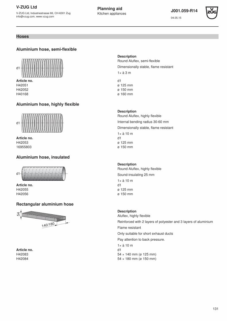
V-ZUG LtdV-ZUG Ltd, Industriestrasse 66, CH-6301 [email protected], www.vzug.com
Planning aidKitchen appliances
J001.059-R1404.05.15
131
Hoses
Aluminium hose, semi-flexible
Description
d1
Round Aluflex, semi-flexible
Dimensionally stable, flame resistant
1× à 3 m
Article no. d1H42051 ø 125 mmH42052 ø 150 mmH40168 ø 160 mm
Aluminium hose, highly flexible
Description
d1
Round Aluflex, highly flexible
Internal bending radius 30-60 mm
Dimensionally stable, flame resistant
1× à 10 mArticle no. d1H42053 ø 125 mm16955803 ø 150 mm
Aluminium hose, insulated
Description
d1
Round Aluflex, highly flexible
Sound-insulating 25 mm
1× à 10 mArticle no. d1H42055 ø 125 mmH42056 ø 150 mm
Rectangular aluminium hose
54
140/180
DescriptionAluflex, highly flexible
Reinforced with 2 layers of polyester and 3 layers of aluminium
Flame resistant
Only suitable for short exhaust ducts
Pay attention to back pressure.
1× à 10 mArticle no. d1H42083 54 × 140 mm (ø 125 mm)H42084 54 × 180 mm (ø 150 mm)
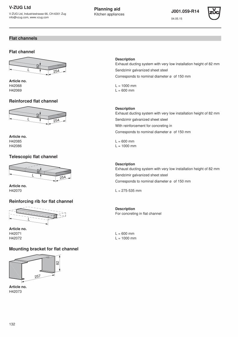
V-ZUG LtdV-ZUG Ltd, Industriestrasse 66, CH-6301 [email protected], www.vzug.com
Planning aidKitchen appliances
J001.059-R1404.05.15
132
Flat channels
Flat channel
82
254L
DescriptionExhaust ducting system with very low installation height of 82 mm
Sendzimir galvanized sheet steel
Corresponds to nominal diameter ø of 150 mmArticle no.H42068 L = 1000 mmH42069 L = 600 mm
Reinforced flat channel
82
254L
DescriptionExhaust ducting system with very low installation height of 82 mm
Sendzimir galvanized sheet steel
With reinforcement for concreting in
Corresponds to nominal diameter ø of 150 mmArticle no.H42085 L = 600 mmH42086 L = 1000 mm
Telescopic flat channel
254L
82
DescriptionExhaust ducting system with very low installation height of 82 mm
Sendzimir galvanized sheet steel
Corresponds to nominal diameter ø of 150 mmArticle no.H42070 L = 275-535 mm
Reinforcing rib for flat channel
L
DescriptionFor concreting in flat channel
Article no.H42071 L = 600 mmH42072 L = 1000 mm
Mounting bracket for flat channel
257
82
Article no.H42073

V-ZUG LtdV-ZUG Ltd, Industriestrasse 66, CH-6301 [email protected], www.vzug.com
Planning aidKitchen appliances
J001.059-R1404.05.15
133
Elbow 90°, vertical, for flat channel
14
0
2548
2
Article no.H42074
Elbow 45°, vertical, for flat channel
16
0
254
82
Article no.H42075
Elbow 90°, horizontal, for flat channel
254
315
82
Article no.H42076
Elbow 45°, horizontal, for flat channel
254
280
82
Article no.H42077

V-ZUG LtdV-ZUG Ltd, Industriestrasse 66, CH-6301 [email protected], www.vzug.com
Planning aidKitchen appliances
J001.059-R1404.05.15
134
Transition piece for flat channel
14
5
254
82
d1 DescriptionFor transitioning from round to flat
Article no.H42078
Diverter piece on flat channel
60
82
115
200 254
Article no.H42087 Connection ø 125 mmH42079 Connection ø 150 mm
Flat channel wall box
15
0
150300
DescriptionWith non-return flap valve and weather protection grille
Article no.H42054
Sealing tape
Aluminium tape
DescriptionFabric-reinforced tape, with protective film
50 mm × 50 m roll
Article no.H42067
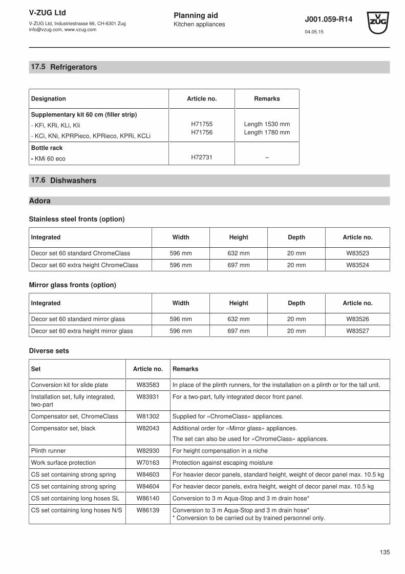
V-ZUG LtdV-ZUG Ltd, Industriestrasse 66, CH-6301 [email protected], www.vzug.com
Planning aidKitchen appliances
J001.059-R1404.05.15
135
17.5 Refrigerators
Designation Article no. Remarks
Supplementary kit 60 cm (filler strip)
- KFi, KRi, KLi, KIi
- KCi, KNi, KPRPieco, KPRieco, KPRi, KCLi
H71755H71756
Length 1530 mmLength 1780 mm
Bottle rack
- KMi 60 eco H72731 –
17.6 Dishwashers
Adora
Stainless steel fronts (option)
Integrated Width Height Depth Article no.
Decor set 60 standard ChromeClass 596 mm 632 mm 20 mm W83523
Decor set 60 extra height ChromeClass 596 mm 697 mm 20 mm W83524
Mirror glass fronts (option)
Integrated Width Height Depth Article no.
Decor set 60 standard mirror glass 596 mm 632 mm 20 mm W83526
Decor set 60 extra height mirror glass 596 mm 697 mm 20 mm W83527
Diverse sets
Set Article no. Remarks
Conversion kit for slide plate W83583 In place of the plinth runners, for the installation on a plinth or for the tall unit.
Installation set, fully integrated,two-part
W83931 For a two-part, fully integrated decor front panel.
Compensator set, ChromeClass W81302 Supplied for «ChromeClass» appliances.
Compensator set, black W82043 Additional order for «Mirror glass» appliances.
The set can also be used for «ChromeClass» appliances.
Plinth runner W82930 For height compensation in a niche
Work surface protection W70163 Protection against escaping moisture
CS set containing strong spring W84603 For heavier decor panels, standard height, weight of decor panel max. 10.5 kg
CS set containing strong spring W84604 For heavier decor panels, extra height, weight of decor panel max. 10.5 kg
CS set containing long hoses SL W86140 Conversion to 3 m Aqua-Stop and 3 m drain hose*
CS set containing long hoses N/S W86139 Conversion to 3 m Aqua-Stop and 3 m drain hose** Conversion to be carried out by trained personnel only.
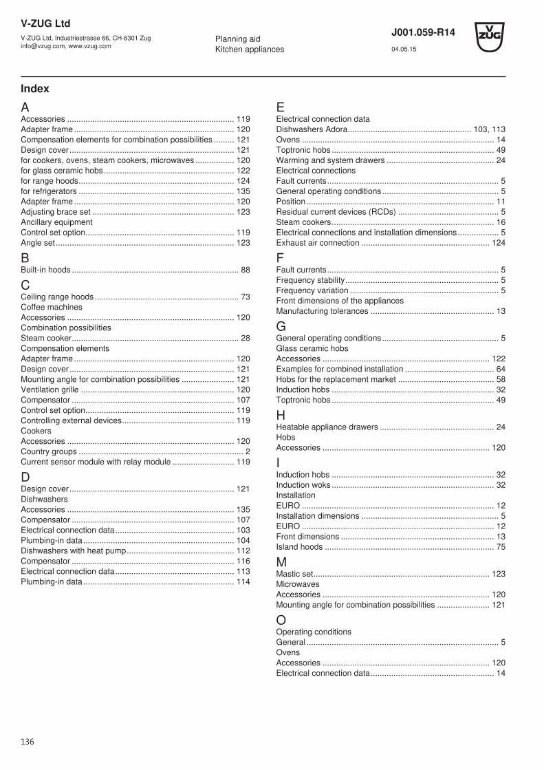
V-ZUG LtdV-ZUG Ltd, Industriestrasse 66, CH-6301 [email protected], www.vzug.com
Planning aidKitchen appliances
J001.059-R1404.05.15
Index
AAccessories ......................................................................... 119Adapter frame ...................................................................... 120Compensation elements for combination possibilities ......... 121Design cover........................................................................ 121for cookers, ovens, steam cookers, microwaves ................. 120for glass ceramic hobs......................................................... 122for range hoods.................................................................... 124for refrigerators .................................................................... 135Adapter frame ...................................................................... 120Adjusting brace set .............................................................. 123Ancillary equipmentControl set option................................................................. 119Angle set.............................................................................. 123
BBuilt-in hoods ......................................................................... 88
CCeiling range hoods............................................................... 73Coffee machinesAccessories ......................................................................... 120Combination possibilitiesSteam cooker......................................................................... 28Compensation elementsAdapter frame ...................................................................... 120Design cover........................................................................ 121Mounting angle for combination possibilities ....................... 121Ventilation grille ................................................................... 120Compensator ....................................................................... 107Control set option................................................................. 119Controlling external devices................................................. 119CookersAccessories ......................................................................... 120Country groups ........................................................................ 2Current sensor module with relay module ........................... 119
DDesign cover........................................................................ 121DishwashersAccessories ......................................................................... 135Compensator ....................................................................... 107Electrical connection data.................................................... 103Plumbing-in data.................................................................. 104Dishwashers with heat pump............................................... 112Compensator ....................................................................... 116Electrical connection data.................................................... 113Plumbing-in data.................................................................. 114
EElectrical connection dataDishwashers Adora...................................................... 103, 113Ovens .................................................................................... 14Toptronic hobs ....................................................................... 49Warming and system drawers ............................................... 24Electrical connectionsFault currents........................................................................... 5General operating conditions................................................... 5Position .................................................................................. 11Residual current devices (RCDs) ............................................ 5Steam cookers....................................................................... 16Electrical connections and installation dimensions.................. 5Exhaust air connection ........................................................ 124
FFault currents........................................................................... 5Frequency stability................................................................... 5Frequency variation ................................................................. 5Front dimensions of the appliancesManufacturing tolerances ...................................................... 13
GGeneral operating conditions................................................... 5Glass ceramic hobsAccessories ......................................................................... 122Examples for combined installation ....................................... 64Hobs for the replacement market .......................................... 58Induction hobs ....................................................................... 32Toptronic hobs ....................................................................... 49
HHeatable appliance drawers .................................................. 24HobsAccessories ......................................................................... 120
IInduction hobs ....................................................................... 32Induction woks ....................................................................... 32InstallationEURO .................................................................................... 12Installation dimensions ............................................................ 5EURO .................................................................................... 12Front dimensions ................................................................... 13Island hoods .......................................................................... 75
MMastic set............................................................................. 123MicrowavesAccessories ......................................................................... 120Mounting angle for combination possibilities ....................... 121
OOperating conditionsGeneral .................................................................................... 5OvensAccessories ......................................................................... 120Electrical connection data...................................................... 14
136
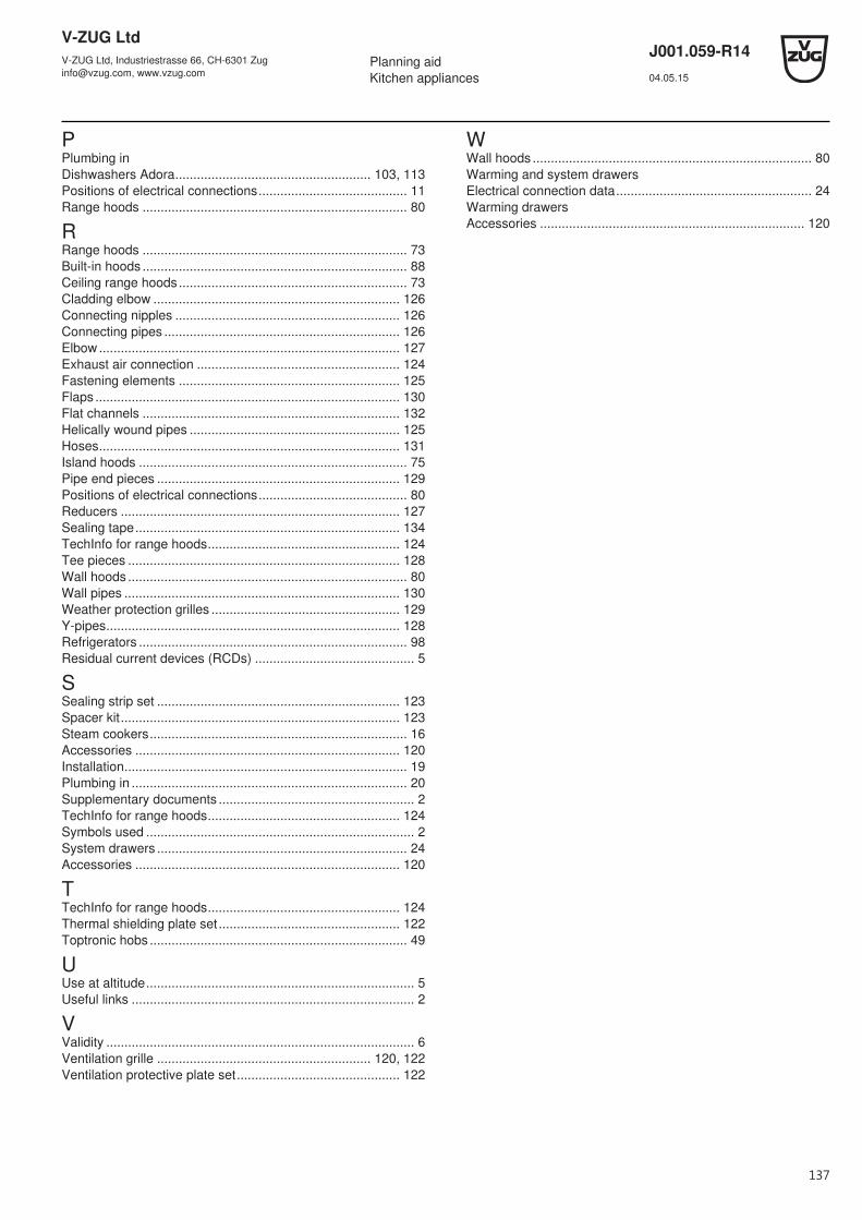
V-ZUG LtdV-ZUG Ltd, Industriestrasse 66, CH-6301 [email protected], www.vzug.com
Planning aidKitchen appliances
J001.059-R1404.05.15
PPlumbing inDishwashers Adora...................................................... 103, 113Positions of electrical connections......................................... 11Range hoods ......................................................................... 80
RRange hoods ......................................................................... 73Built-in hoods ......................................................................... 88Ceiling range hoods............................................................... 73Cladding elbow .................................................................... 126Connecting nipples .............................................................. 126Connecting pipes ................................................................. 126Elbow................................................................................... 127Exhaust air connection ........................................................ 124Fastening elements ............................................................. 125Flaps .................................................................................... 130Flat channels ....................................................................... 132Helically wound pipes .......................................................... 125Hoses................................................................................... 131Island hoods .......................................................................... 75Pipe end pieces ................................................................... 129Positions of electrical connections......................................... 80Reducers ............................................................................. 127Sealing tape......................................................................... 134TechInfo for range hoods..................................................... 124Tee pieces ........................................................................... 128Wall hoods ............................................................................. 80Wall pipes ............................................................................ 130Weather protection grilles .................................................... 129Y-pipes................................................................................. 128Refrigerators .......................................................................... 98Residual current devices (RCDs) ............................................ 5
SSealing strip set ................................................................... 123Spacer kit............................................................................. 123Steam cookers....................................................................... 16Accessories ......................................................................... 120Installation.............................................................................. 19Plumbing in ............................................................................ 20Supplementary documents ...................................................... 2TechInfo for range hoods..................................................... 124Symbols used .......................................................................... 2System drawers ..................................................................... 24Accessories ......................................................................... 120
TTechInfo for range hoods..................................................... 124Thermal shielding plate set.................................................. 122Toptronic hobs ....................................................................... 49
UUse at altitude.......................................................................... 5Useful links .............................................................................. 2
VValidity ..................................................................................... 6Ventilation grille ........................................................... 120, 122Ventilation protective plate set............................................. 122
WWall hoods ............................................................................. 80Warming and system drawersElectrical connection data...................................................... 24Warming drawersAccessories ......................................................................... 120
137
V-ZUG LtdV-ZUG Ltd, Industriestrasse 66, CH-6301 [email protected], www.vzug.com
Planning aidKitchen appliances
J001.059-R1404.05.15
138
Notes
V-ZUG LtdV-ZUG Ltd, Industriestrasse 66, CH-6301 [email protected], www.vzug.com
Planning aidKitchen appliances
J001.059-R1404.05.15
139
CONTACT IN THE COUNTRIES
Australia: V-ZUG Australia Pty. Ltd2/796 High Street East Kew Vic 3102PO Box 864, Kew 3101, VICAustraliaTel. +61 3 9832 [email protected]
Israel: Isfar Consumer Products Ltd.7 Sapir street Industrial Zone46852 HerzliyaIsraelTel. +972 180 030 80 90
Russia: OOO HomeTek ulista Shepkina 25/20129090 MoscowRussian FederationTel. +7 495 781 00 55Fax +7 495 781 00 55
Belgium & Luxembourg:V-ZUG Europe BVBAEvolis 1028530 Harelbeke, BelgiumTel. 00800 850 850 00Tel. +32 56 61 60 [email protected]
Italy: FRIGO 2000 SERVICE SRLVia Mazzini 520835 Muggiò (MI), ItalyTel. +39 039 79 09 [email protected]
Singapore & Malaysia:KHL Marketing Asia Pacific Pte LtdKHL Building25 New Industrial Road no. 02-01SG-536211 SingaporeTel. +65 630 890 88 (Singapore)Tel. +60 322 875 010 (Malaysia)[email protected]
China: V-ZUG (Shanghai) Co., Ltd1344, 1350 Yuyuan RoadChangning District200050 Shanghai, ChinaTel. +86 400 820 16 [email protected]
Lebanon: C-Design ShowroomConcept Design Unlimited sarlAshrafieh – Ashrafieh St.Beirut, LebanonTel. +961 12 05 [email protected]
Turkey: HACK Ltd. Şti.Tekstilkent Koza Plaza A-Blok Kat: 11 No: 4034235 Esenler/İstanbul, TurkeyTel: +90 800 211 03 [email protected]
Germany: V-ZUG Europe BVBASchlossstraße 14b, 1st floor82031 Grünwald, GermanyTel. 00800 850 850 [email protected]
The Netherlands: V-ZUG Europe BVBAEvolis 1028530 Harelbeke, BelgiumTel. 00800 850 850 [email protected]
United Kingdom & Ireland: V-ZUG Europe BVBAEvolis 1028530 Harelbeke, BelgiumTel. +44 843 289 57 [email protected]
France: V-ZUG Europe BVBA3, rue de Téhéran75008 Paris, FranceTel. 00800 850 850 00Tel. +32 56 61 60 [email protected]
Norway & Sweden: Rikall Norge ASHylkjeflaten 18, inngang B5109 Hylkje, NorwayTel. +47 55 53 44 [email protected]
Ukraine: MIRS CorporationOsipova street 37, Office 55065012 Odessa, UkraineTel. +38 482 30 55 [email protected]
CONTACT IN SWITZERLAND V-ZUG LtdIndustriestrasse 66, 6301 ZugSwitzerland
Service & Support InternationalTel. +41 58 767 67 [email protected]