
ITER catalogue for I&C products - Slow controllers PLC 2/7-ITER... · ITER catalogue for I&C...
25
PDF generated on 05-Feb-2013 DISCLAIMER : UNCONTROLLED WHEN PRINTED – PLEASE CHECK THE STATUS OF THE DOCUMENT IN IDM How To ITER catalogue for I&C products - Slow controllers PLC This document contains the list of Siemens S7 components to be used within Plant Systems for slow controls and SIL-2 and 3 purposes. Approval Process Name Action Affiliation Author Evrard B. 22-Jan-2013:signed IO/DG/DIP/CHD/CSD/PCI CoAuthor Reviewers Yonekawa I. 25-Jan-2013:recommended IO/DG/DIP/CHD/CSD/PCI Approver Wallander A. 05-Feb-2013:approved IO/DG/DIP/CHD/CSD Document Security: level 1 (IO unclassified) RO: Evrard Bruno Read Access AD: ITER, AD: External Collaborators, AD: Division - Control System Division - EXT, AD: Section - CODAC - EXT, AD: Section - CODAC, project administrator, RO, LG: PLC group, LG: CODAC team, AD: Section - Plant Control and Instrumentation IDM UID 333J63 VERSION CREATED ON / VERSION / STATUS 13 Dec 2012 / 3.1/ Approved EXTERNAL REFERENCE
Transcript of ITER catalogue for I&C products - Slow controllers PLC 2/7-ITER... · ITER catalogue for I&C...
PDF generated on 05-Feb-2013DISCLAIMER : UNCONTROLLED WHEN PRINTED – PLEASE CHECK THE STATUS OF THE DOCUMENT IN IDM
How To
ITER catalogue for I&C products - Slow controllers PLC
This document contains the list of Siemens S7 components to be used within Plant Systems for slow controls and SIL-2 and 3 purposes.
Approval Process Name Action AffiliationAuthor Evrard B. 22-Jan-2013:signed IO/DG/DIP/CHD/CSD/PCICoAuthorReviewers Yonekawa I. 25-Jan-2013:recommended IO/DG/DIP/CHD/CSD/PCIApprover Wallander A. 05-Feb-2013:approved IO/DG/DIP/CHD/CSD
Document Security: level 1 (IO unclassified)RO: Evrard Bruno
Read Access AD: ITER, AD: External Collaborators, AD: Division - Control System Division - EXT, AD: Section - CODAC - EXT, AD: Section - CODAC, project administrator, RO, LG: PLC group, LG: CODAC team, AD: Section - Plant Control and Instrumentation
IDM UID
333J63VERSION CREATED ON / VERSION / STATUS
13 Dec 2012 / 3.1/ Approved
EXTERNAL REFERENCE

PDF generated on 05-Feb-2013DISCLAIMER : UNCONTROLLED WHEN PRINTED – PLEASE CHECK THE STATUS OF THE DOCUMENT IN IDM
Change Log
Title (Uid) Version
Latest Status Issue Date Description of Change
ITER catalogue for I&C products - Slow controllers PLC (333J63_v3_1)
v3.1 Approved 13 Dec 2012
- Update of Satelite Documents picture.
- Update Reviewers and Approver
- Addition of Exploded view for s7-400 Rack
ITER catalogue for I&C products - Slow controllers PLC (333J63_v3_0)
v3.0 Signed 03 Dec 2012
Complete Re-shuffling.
References moved to another living document
Addition of gudielines for architectures
ITER catalogue for I&C products - Slow controllers PLC (333J63_v2_0)
v2.0 In Work 22 Oct 2012
Catalog organization completely Re-shuffled.
TAble of Content is different.
ITER catalogue for I&C products - Slow controllers PLC (333J63_v1_7)
v1.7 Approved 09 Feb 2011
Version updated after PCDH review.
ITER catalogue for I&C products - Slow controllers PLC (333J63_v1_6)
v1.6 Signed 06 Jan 2011
New RO: B Evrard
ITER catalogue for I&C products - Slow controllers PLC (333J63_v1_5)
v1.5 Signed 17 Nov 2010
Add 6ES7971-0BA00 within section 3.4.2
Add 6ES7952-1AM00-0AA0 within section 3.5.3
Add 6ES7960-1AA04-0XA0 within section 3.5.3
Add section 3.5.7
Add 6ES7922-3BD00-0AS0 within section 3.6.5
Add 6ES7922-3BD00-0AN0 within section 3.6.5
ITER catalogue for I&C products - Slow controllers PLC (333J63_v1_4)
v1.4 Signed 28 Oct 2010
Replace 6ES7307-1EA00-0AA0 by 6ES7307-1EA01-0AA0 within section 3.1.2
Add reference S7 PLC ordering process (https://user.iter.org/?uid=3Q6UQ3)
ITER catalogue for I&C products - Slow controllers PLC (333J63_v1_3)
v1.3 Signed 22 Oct 2010
Replace 6ES7390-1BC00-0AA0 by 6ES7390-1AJ30-0AA0 within section 3.1.1
Replace 6ES7341-1CH02 by 6ES7341-1CH02-0AE0 within section 3.1.5
Replace 6ES7193-4CC20-0AA0 by 6ES7193-4CC30-0AA0 within section 3.3.2
ITER catalogue for I&C products - Slow
v1.2 Signed 31 Aug Update of documentation links, minor syntax

PDF generated on 05-Feb-2013DISCLAIMER : UNCONTROLLED WHEN PRINTED – PLEASE CHECK THE STATUS OF THE DOCUMENT IN IDM
controllers PLC (333J63_v1_2)
2010 changes, change of module references:
Replace 6ES7 317-2EK13-0AB0 by 6ES7 317-2EK14-0AB0 within section 3.1.3
Replace 353-1AH01-0AE0 by 6ES7353-1AH01-0AE0 within section 3.2.6
Replace 6ES7 75710-8MA11 by 6ES5710-8MA11 within section 3.3.1
Replace 6ES7 8GL11-0AA0 by 6ES7 8LG11-0AA0 within section 3.3.3
Replace 6ES7 416-3 PN 3ER05-0AB0 by 6ES7 416-3ER05-0AB0 within section 3.4.3
Replace 6GK7 443-1EX20-0EX0 by 6GK7 443-1EX20-0XE0 within section 3.4.4
Replace 6ES7 414-FH by 6ES7414HM14-0AB0 within section 3.5.3
Replace 6ES7 960-1AA04-5BK0 by 6ES7 960-1AA04-0XA0 within section 3.5.5
Replace 6ES7153-1BK00-0AB0 by 6ES7153-1BK00-0XB0 within section 3.5.5
Replace 6ES7326-1BK01-0AB0 by 6ES7326-1BK02-0AB0 within section 3.6.4
Replace 6ES7326-2BF01-0AB0 by 6ES7326-2BF10-0AB0 within section 3.6.4
Replace 6ES7650-1KA11-7XX0 by 6ES7650-1AK11-7XX0 within section 3.6.5
Replace 6ES7 138-4CF02-0AA0 by 6ES7138-4CF03-0AB0 within section 3.7.2
Replace 6ES7 953-8GL11-0AA0 by 6ES7953-8LG11-0AA0 within section 3.7.3
ITER catalogue for I&C products - Slow controllers PLC (333J63_v1_1)
v1.1 Approved 01 Feb 2010
Updated for version %5.1 of PCDH
ITER catalogue for I&C products - Slow controllers PLC (333J63_v1_0)
v1.0 Signed 10 Dec 2009
PLC Software Engineering Handbook Page 1 of 22
Table of Contents
Table of Contents ........................................................................................................................1Table of Figures...........................................................................................................................21 Introduction.........................................................................................................................3
1.1 Purpose of document ..................................................................................................31.2 Scope.............................................................................................................................31.3 Acronyms.....................................................................................................................41.4 Definitions....................................................................................................................41.5 Reference Documents .................................................................................................4
2 Reference system.................................................................................................................53 System Selection ..................................................................................................................6
3.1 Controller type selection.............................................................................................73.2 CPU Rack Selection ....................................................................................................83.3 IO Racks Selection ....................................................................................................103.4 Field Network Selection............................................................................................11
4 Systems Composition ........................................................................................................124.1 Mid range PLCs: s7-300..........................................................................................124.2 High range PLCs: s7-400.........................................................................................124.3 I/O modules ET200S.................................................................................................154.4 I/O modules ET200M ...............................................................................................154.5 High Availability, High range PLCs: s7-400 “H”..................................................154.6 Fail-Safe, Mid range PLCs: s7-300 “F” ..................................................................164.7 Fail-Safe, High range PLCs: s7-400 “F”.................................................................164.8 High Availability, Fail Safe, High range PLCs: s7-400 “FH” .............................164.9 Fail-Safe I/O modules ET200S –“F” .......................................................................174.10 Fail-Safe I/O modules ET200M –“F”......................................................................174.11 Accessories .................................................................................................................18
5 Networks ............................................................................................................................196 Cubicle Monitoring System..............................................................................................207 Software Packages ............................................................................................................218 Annexe: Siemens Reference List......................................................................................22

Document Title Page 2 of 22
Table of FiguresFigure 1: PCDH documents for plant control system design phase ____________________3Figure 2: Plant Control System Design Workflow __________________________________6Figure 3: Hardware selection flowchart __________________________________________7Figure 4: CPU Selection flowchart ______________________________________________9Figure 5: Rack s7-400 exploded view. _________________________________________13Figure 6 – Schema of PCDH documents ________________________________________22
Document Title Page 3 of 22
1 Introduction
1.1 Purpose of document
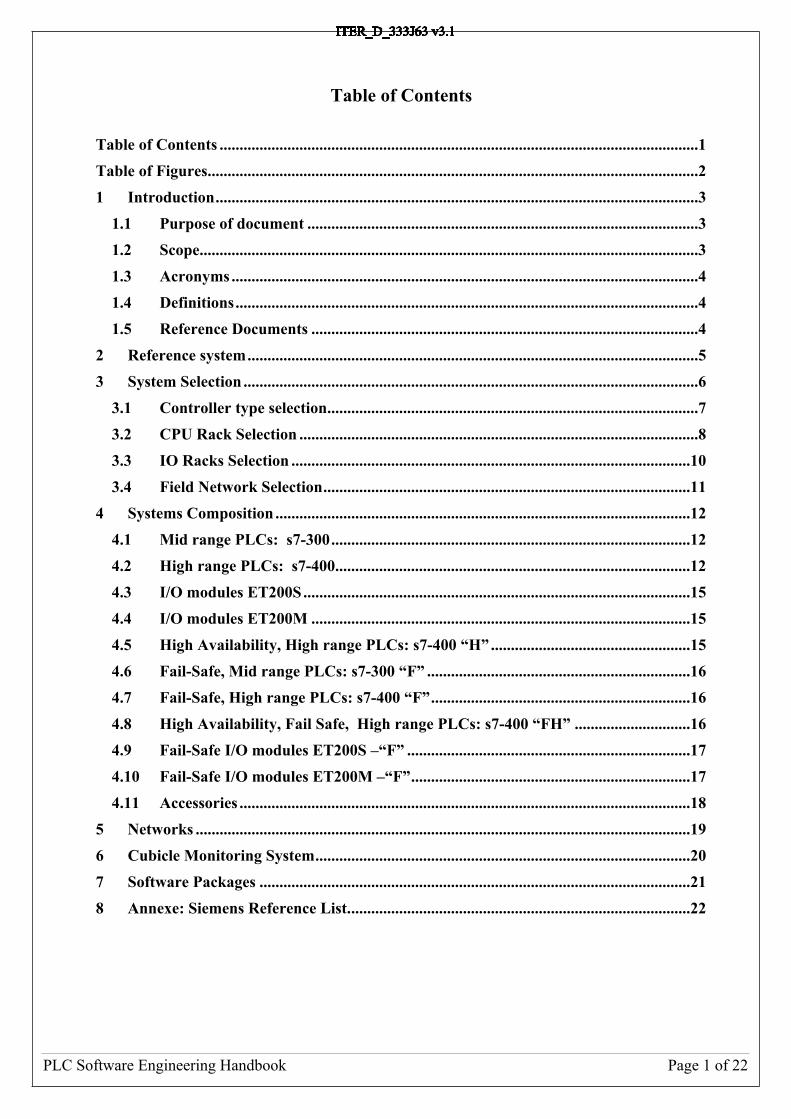
Plant Control Design Handbook (PCDH) document defines standards for all ITER plant system instrumentation and control (I&C). These standards are essential in order to achieve an integrated, maintainable and affordable control system to operate ITER. This satellite document of PCDH, “Siemens S7 PLC I/O Catalogue” gives a list of COTS products recommended by ITER Organization. See Figure 1.The purpose of this catalogue is to define the list of modules to be used by the different plant system suppliers across all the domestic agencies and their subcontractors participating in ITER.This catalogue shall be used for every slow control application.If the application requirements are not fulfilled, the deviation procedure will be triggered.Accessories for wiring and installation will be in the appendices.
Core PCDH (27LH2V)Plant system control philosophyPlant system control Life CyclePlant system control specificationsCODAC interface specificationsInterlock I&C specificationSafety I&C specification
PCDH core and satellite documents: v7PS CONTROL DESIGN
Plant system I&C architecture (32GEBH)
Methodology for PS I&C specifications (353AZY)
CODAC Core System Overview (34SDZ5) INTERLOCK CONTROLS
Guidelines for PIS design (3PZ2D2)
Guidelines for PIS integration & config. (7LELG4)
Management of local interlock functions (75ZVTY)
PIS Operation and Maintenance (7L9QXR)
I&C CONVENTIONSI&C Signal and variable naming (2UT8SH)
ITER CODAC Glossary (34QECT)
ITER CODAC Acronym list (2LT73V)
PS SELF DESCRIPTION DATASelf description schema documentation (34QXCP)
CATALOGUES for PS CONTROLSlow controllers products (333J63)
Fast controller products (345X28)
Cubicle products (35LXVZ)
Integration kit for PS I&C (C8X9AE)
PS CONTROL INTEGRATIONThe CODAC -PS Interface (34V362)
PS I&C integration plan (3VVU9W)
ITER alarm system management (3WCD7T)
ITER operator user interface (3XLESZ)
Guidelines for PON archiving (B7N2B7)
PS Operating State management (AC2P4J)
Guidelines for Diagnostic data structure (354SJ3)PS CONTROL DEVELOPMENT
I&C signal interface (3299VT)
PLC software engineering handbook (3QPL4H)
Guidelines for fast controllers (333K4C)
Software engineering and QA for CODAC (2NRS2K)
Guidelines for I&C cubicle configurations (4H5DW6)
CWS case study specifications (35W299)
NUCLEAR PCDH (2YNEFU)
OCCUPATIONAL SAFETY CONTROLSGuidelines for PSS design (C99J7G)
Available and approved
Legend
This document
(XXXXXX) IDM ref.
Slow controllers products (333J63)
Figure 1: PCDH documents for plant control system design phase
In all the document, the commonly used term “I&C” is replaced by “Control System” or “Plant Control System”
1.2 Scope
This document covers Control System Design with conventional controllers, interlock controllers and Occupational Safety Controllers. Nuclear Safety controllers are not covered in this document.
1.3 Acronyms
AI Analogue Input

Document Title Page 4 of 22
AO Analogue OutputCIN Central Interlock Network CIS Central Interlock System CODAC COntrol Data Access and Communications COTS Commercial Off the ShelfDA Domestic AgencyDC Direct CurrentDI Digital InputDO Digital OutputI&C Instrumentation & ControlI/O Input / OutputIO ITER OrganizationIEC International Electrotechnical CommissionIP Internet ProtocolLED Light Emitting DiodeNTP Network Time ProtocolPCDH Plant Control Design Handbook PLC Programmable Logic ControllerPS Plant SystemPSH Plant System HostSIL Safety Integrity LevelTBC To Be ConfirmedTBD To Be DefinedUPS Uninterruptible Power Supply1oo2 One out Of Two2oo3 Two out Of Three
1.4 Definitions
1.5 Reference Documents
IDM Number Title[RD 1] PCDH[RD 2] Network Infrastructure[RD 3] Integration Kit[RD 4] PLC Software Engineering Handbook[RD 5] PLC References for Plant Control Systems Design

Document Title Page 5 of 22
2 Reference system
In the document, no Manufacture Reference will be mentioned. Every product will be associated to a Short Designation. All Manufacture references are specified in another document: [RD 5]. The reason is that references may change frequently and would make this document obsolete almost every 3 months. So the products are designed by a Short Designation, itself pointing to a Manufacturer reference in the other document.
Example:
Short Designation Description Product Reference Status
CPU317-2 CPU 317-2 PN/DP (2x Eth) 6ES7317-2EK14-0AB0 Active

Document Title Page 6 of 22
3 System SelectionThis document assumes that data are already available from the conceptual design phase of the Control System:
- A functional analysis is available- The Control functions have been allocated in some controllers.
This document is a tool to help building the next phase: the detailed architecture. Basically, choosing the hardware for controllers.
ConsolidatedFunctional
Analysis
Conceptual Architecture
Cubicle Design(CAD)
- Control Logic, Feedback Loops, Sequences Diagrams.- HMI Configuration States and Commmands.- Function Reliability Requirements- ...
Electrical Design
Pneumatic Design
Mechanical Design
Process Design
Electronic Devices Design
Plant Control System Design System Manufacture
Detailed Architecture
CADs
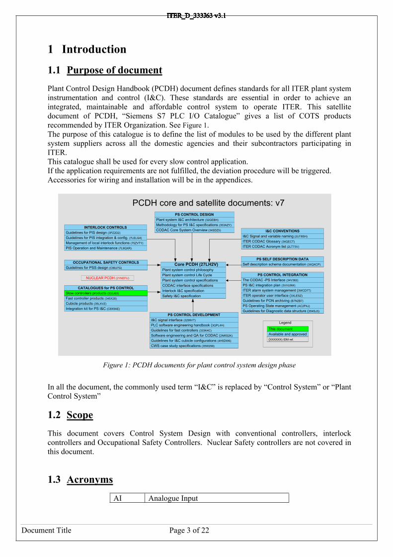
Figure 2: Plant Control System Design WorkflowThe following figure is a flowchart representation of the major steps to choose the hardware. Note that the choice of I/O modules and the Field Network Technology can be done in parallel, as both topics are closely related.
Document Title Page 7 of 22
START
Controller Type Selection
(Fast, PLC)
PLC Range Selection
(300-400,”F”,”H”)
I/O Selections
END
Network Selection
Figure 3: Hardware selection flowchart
3.1 Controller type selection
While it is not in the scope of this document, here is a suggestion of the different criteria’s to take into account, when choosing between a Fast Controller and a Slow Controller (a PLC). In a scientific experiment, the term “slow control” is used for controllers in charge of the industrial services of the experiment: vacuum, water cooling, steam, etc… While Fast Controllers are usually in charge of functions directly implied in the experiment
- The performance criteria’s. They are exclusive. o If the process requires fast regulation loops, a fast Controller will be used.
Usually PLC analog signals board have poor performances. While it is difficult to give a strict boundary, 0,5Hz can be taken as a magnitude.
o If response time required to discrete events is extremely short, it may be better to consider a Fast Controller. It is also difficult to give a strict boundary, because the PLC reaction time highly depends on the cycle time. 10msecs can be taken as a magnitude.
- Connection to SDN and TCN. PLCs have not interface possible to SDN and TCN, so if the controller requires this interface, it should be a Fast Controller.
- The position of the controller in the experiment. In a scientific experiment, the term “slow control” is used for controllers in charge of the industrial services of the experiment: vacuum, water cooling, steam, etc… While Fast Controllers are usually
Document Title Page 8 of 22
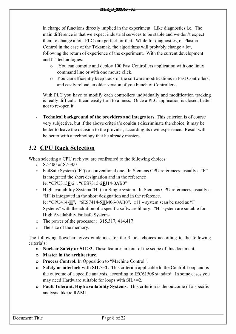
in charge of functions directly implied in the experiment. Like diagnostics i.e. The main difference is that we expect industrial services to be stable and we don’t expect them to change a lot. PLCs are perfect for that. While for diagnostics, or Plasma Control in the case of the Tokamak, the algorithms will probably change a lot, following the return of experience of the experiment. With the current development and IT technologies:
o You can compile and deploy 100 Fast Controllers application with one linux command line or with one mouse click.
o You can efficiently keep track of the software modifications in Fast Controllers, and easily reload an older version of you bunch of Controllers.
With PLC you have to modify each controllers individually and modification tracking is really difficult. It can easily turn to a mess. Once a PLC application is closed, better not to re-open it.
- Technical background of the providers and integrators. This criterion is of course very subjective, but if the above criteria’s couldn’t discriminate the choice, it may be better to leave the decision to the provider, according its own experience. Result will be better with a technology that he already masters.
3.2 CPU Rack Selection
When selecting a CPU rack you are confronted to the following choices:o S7-400 or S7-300o FailSafe System (“F”) or conventional one. In Siemens CPU references, usually a “F”
is integrated the short designation and in the reference Ie: “CPU315F-2”, “6ES7315-2FJ14-0AB0”
o High availability System(“H”) or Single system. In Siemens CPU references, usually a “H” is integrated in the short designation and in the reference. Ie: “CPU414-H”, “6ES7414-5HM06-0AB0”. « H » system scan be used as “F Systems” with the addition of a specific software library. “H” system are suitable for High Availability Failsafe Systems.
o The power of the processor : 315,317, 414,417o The size of the memory.
The following flowchart gives guidelines for the 3 first choices according to the following criteria’s:
o Nuclear Safety or SIL>3. These features are out of the scope of this document.o Master in the architecture. o Process Control. In Opposition to “Machine Control”. o Safety or interlock with SIL>=2. This criterion applicable to the Control Loop and is
the outcome of a specific analysis, according to IEC61508 standard. In some cases you may need Hardware suitable for loops with SIL>=2.
o Fault Tolerant, High availability Systems. This criterion is the outcome of a specific analysis, like ie RAMI.

Document Title Page 9 of 22
Nuclear Safety or SIL >3?
“300” System
“F” SystemSafety or Interlock SIL >= 2?
Fault-Tolerant, High Availability Requirement?
Out of scope
S7 System
YES
Master in the Architecture
Process
“400" System
“H” SystemYES
END
START
YES
Process ControlYES
YES
Figure 4: CPU Selection flowchart

Document Title Page 10 of 22
3.3 IO Racks Selection
When selecting a CPU rack you are confronted to the following choices:o ET200M or ET200So Fail-Safe or Not.
ET200M and ET200S essential differences:o Number of channels available. ET200M is highly integrated. One big module can
integrate up to 64 signals. (this catalogue restricts to 32 signals module)o ET200S can be expended with compatible Siemens Frequency Converters.o ET200S has faster analog modules. So faster Control Loops can be achieved.o ET200M is adapted to “Fast Connect” wiring solutions. ET200S have to be wired
directly on the module.o An ET200S module is smaller than an ET200M and can be mounted on a simple DIN
Rail.
Extract of Siemens Catalogue ST70, 2011 version
ET200S ET200M
o Ex approval to Cat. 3 for Zone 2 acc. to ATEX100 a
o Transmission rates up to 12 Mbit/s
o Ex approval to Cat. 3 for Zone 2 acc. to ATEX100 a
o Transmission rates up to 12 Mbit/s
o Distributed I/O system to degree of protection IP20 with minimal wiring outlay, also for extremely time-critical tasks such as high-speed closed-loop controls
o Discretely-modular design for exact adaptation to the automation task in hand.
o Interface modules available with PROFIBUS DP or PROFINET interfaces
o Can be combined from digital and analog in/output modules, technology modules, motor starters and frequency converters for the control of drives up to 7.5 or 4 kW.
o Exchange of modules during operation (hot swapping), permanent wiring with multi-conductor connection
o Channel-specific diagnostics for high
o Modular I/O system with degree of protection IP20, particularly suitable for user-specific and complex automation tasks
o Can be expanded with S7-300 automation system signal, communication and function modules.
o Applicable Ex analog input or output modules with HART optimize the ET 200M for use in process engineering
o Can be used in redundant systems (S7-400H, S7-400F/FH)
o Consists of a PROFIBUS DP IM 153 connection, up to eight or twelve I/O modules of the S7-300 automation system (assembly with bus connections or active bus modules) and if required a power supply
o Modules can be replaced during operation (hot swapping) with the bus

Document Title Page 11 of 22
availabilityo Can be supplied with integrated fiber
optic interface if requiredo FastConnect using unstripped quick
connection technology, screw or spring-loaded terminals
o Slot reservation with spare moduleso Fail-safe DI modules with safety-
related signal processing according to PROFIsafe
Option handling – for simples management of machine options
modules activeo Can be supplied with integrated fiber
optic interface if requiredo Fail-safe digital in/outputs as well as
analog inputs for safety oriented signal processing in accordance with PROFIsafe
o Support of modules with expanded user data, e.g. HART modules with HART minor variables
The choice of Fail-Safe products is driven by the outcome of a specific analysis, according to IEC61508 standard. In some cases you may need Hardware suitable for loops with SIL>=2.
3.4 Field Network Selection
When selecting a Field Network you are confronted to the following choices:- Profibus or Profinet- The Topology
o Staro Ring, o Bus
This topology topic will not be developped here, as it would interfere with other approved documents.The choice between Profibus and Profinet is straightforward. By default choose Profinet, but if your slaves support only Profibus, then choose Profibus. Avoid heterogeneous architectures mixing Profinet and Profibus with bridges. If you application has Profibus and Profinet slaves, then deploy both networks.

Document Title Page 12 of 22
4 Systems Composition
4.1 Mid range PLCs: s7-300
Short Designation Pce Description and Characteristics
RAIL-19IN 1 Rail 19"PS300-5A 1 PS 300 5A (1 Slot)CPU317-2 1 CPU 317-2 PN/DP (2x Eth)MMC-2M-EEPROM 1 Micro Memory Card 2MBCP343-1 1 Communication Processor Ethernet

Document Title Page 13 of 22
4.2 High range PLCs: s7-400
When building this rack you have to choose the size of the memory and the type of communication Processor. The choice of the communication Processor depends on the required communications features: Connection to the PON, to a Profinet Network and to “Horizontal Communications”.
PS400
CPU416
CP443
2xBAT-400
PCCARD-16MB-RAMOR PCCARD-8MB-RAMOR PCCARD-4MB-RAM
UR2
CPU416-3PS400 CP443-1-ADVCP443-1
CPU Profibus DP Interface
CP443-1-ADV Ethernet Interface
“X1”
CP443-1-ADV Ethernet Interface
“X2”OR
CP443-1 Ethernet Interface
CPU Ethernet Interface
Figure 5: Rack s7-400 exploded view.
Short Designation Pce Description and Characteristics
UR2 1 Chassis 400 UR2 9 SlotsPS400-10A 1 PS 400 10ABAT-400 2 Back Up Battery 400PCCARD-4MB-RAM 1 Memory PC Card 4MB RAMPCCARD-8MB-RAM 1 Memory PC Card 8MB RAMPCCARD-16MB-RAM 1 Memory PC Card 16MB RAM

Document Title Page 14 of 22
CPU416-3 1 CPU 416-3 PN/DP Central Unit. Detailed characteristics listed in datasheets.
Profibus DP Interface
Master DP V0 and V1 Slave DP V0
Ethernet Interface
96 connections maximum Profinet open ie, o TCP : 32Kb)o ISO-on-TCP : 32Kb)o UDP : 1452 Bytes)
S7 communications http server Integrated Switch
CP443-1 1 Communication Processor Ethernet
96 Connections maximum Profinet SEND/RECEIVE:
ISO-on-TCP: 8Kb TCP/IP: 8Kb UDP : 2Kb
Open IE (“T” Blocks) ISO-on-TCP: 1452 Bytes
S7 communications http server DHCP Client NTP Client SNMP v1
CP443-1-ADV 1 Communication Processor Ethernet “Advanced”. This CP has 2 interfaces, and support some more protocols.Detailed characteristics listed in datasheets.
For each Interface: 96 Connections maximum Profinet IRT SEND/RECEIVE:
ISO-on-TCP: 8Kb TCP/IP: 8Kb UDP : 2Kb
Open IE (“T” Blocks) ISO-on-TCP: 1452 Bytes
S7 communications
Document Title Page 15 of 22
http server DHCP Client NTP Client SNMP v1 FTP
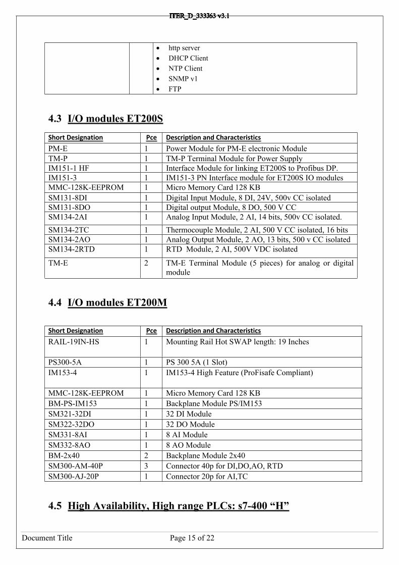
4.3 I/O modules ET200SShort Designation Pce Description and Characteristics
PM-E 1 Power Module for PM-E electronic ModuleTM-P 1 TM-P Terminal Module for Power SupplyIM151-1 HF 1 Interface Module for linking ET200S to Profibus DP. IM151-3 1 IM151-3 PN Interface module for ET200S IO modulesMMC-128K-EEPROM 1 Micro Memory Card 128 KBSM131-8DI 1 Digital Input Module, 8 DI, 24V, 500v CC isolatedSM131-8DO 1 Digital output Module, 8 DO, 500 V CCSM134-2AI 1 Analog Input Module, 2 AI, 14 bits, 500v CC isolated.SM134-2TC 1 Thermocouple Module, 2 AI, 500 V CC isolated, 16 bitsSM134-2AO 1 Analog Output Module, 2 AO, 13 bits, 500 v CC isolatedSM134-2RTD 1 RTD Module, 2 AI, 500V VDC isolated
TM-E 2 TM-E Terminal Module (5 pieces) for analog or digital module
4.4 I/O modules ET200M
Short Designation Pce Description and Characteristics
RAIL-19IN-HS 1 Mounting Rail Hot SWAP length: 19 Inches
PS300-5A 1 PS 300 5A (1 Slot)IM153-4 1 IM153-4 High Feature (ProFisafe Compliant)
MMC-128K-EEPROM 1 Micro Memory Card 128 KBBM-PS-IM153 1 Backplane Module PS/IM153SM321-32DI 1 32 DI ModuleSM322-32DO 1 32 DO ModuleSM331-8AI 1 8 AI ModuleSM332-8AO 1 8 AO ModuleBM-2x40 2 Backplane Module 2x40SM300-AM-40P 3 Connector 40p for DI,DO,AO, RTDSM300-AJ-20P 1 Connector 20p for AI,TC
4.5 High Availability, High range PLCs: s7-400 “H”

Document Title Page 16 of 22
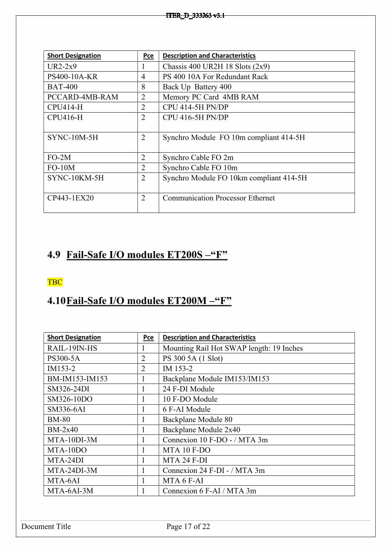
Short Designation Pce Description and Characteristics
UR2-2x9 1 Chassis 400 UR2H 18 Slots (2x9)PS400-10A-KR 4 PS 400 10A For Redundant RackBAT-400 8 Back Up Battery 400PCCARD-4MB-RAM 2 Memory PC Card 4MB RAMCPU414-H 2 CPU 414-5H PN/DPCPU416-H 2 CPU 416-5H PN/DPSYNC-10M-5H 2 Synchro Module FO 10m compliant 414-5H
FO-2M 2 Synchro Cable FO 2mFO-10M 2 Synchro Cable FO 10mSYNC-10KM-5H 2 Synchro Module FO 10km compliant 414-5H
CP443-1EX20 2 Communication Processor Ethernet
4.6 Fail-Safe, Mid range PLCs: s7-300 “F”
Short Designation Pce Description and Characteristics
RAIL-19IN 1 Rail 19"PS300-5A 1 PS 300 5A (1 Slot)CPU315F-2 1 CPU 315F-2 PN/DP MMC-2M-EEPROM 1 Micro Memory Card 2MBCP343-1 1 Communication Processor Ethernet
4.7 Fail-Safe, High range PLCs: s7-400 “F”
Short Designation Pce Description and Characteristics
UR2 1 Chassis 400 UR2 9 SlotsPS400-10A 1 PS 400 10ABAT-400 2 Back Up Battery 400PCCARD-4MB-RAM 1 Memory PC Card 4MB RAMCPU414-H 1 CPU 414-5H PN/DPCP443-1EX20 1 Communication Processor Ethernet
4.8 High Availability, Fail Safe, High range PLCs: s7-400 “FH”
Document Title Page 17 of 22
Short Designation Pce Description and Characteristics
UR2-2x9 1 Chassis 400 UR2H 18 Slots (2x9)PS400-10A-KR 4 PS 400 10A For Redundant RackBAT-400 8 Back Up Battery 400PCCARD-4MB-RAM 2 Memory PC Card 4MB RAMCPU414-H 2 CPU 414-5H PN/DPCPU416-H 2 CPU 416-5H PN/DP
SYNC-10M-5H 2 Synchro Module FO 10m compliant 414-5H
FO-2M 2 Synchro Cable FO 2mFO-10M 2 Synchro Cable FO 10mSYNC-10KM-5H 2 Synchro Module FO 10km compliant 414-5H
CP443-1EX20 2 Communication Processor Ethernet
4.9 Fail-Safe I/O modules ET200S –“F”
TBC
4.10Fail-Safe I/O modules ET200M –“F”
Short Designation Pce Description and Characteristics
RAIL-19IN-HS 1 Mounting Rail Hot SWAP length: 19 InchesPS300-5A 2 PS 300 5A (1 Slot)IM153-2 2 IM 153-2BM-IM153-IM153 1 Backplane Module IM153/IM153SM326-24DI 1 24 F-DI ModuleSM326-10DO 1 10 F-DO ModuleSM336-6AI 1 6 F-AI ModuleBM-80 1 Backplane Module 80BM-2x40 1 Backplane Module 2x40MTA-10DI-3M 1 Connexion 10 F-DO - / MTA 3mMTA-10DO 1 MTA 10 F-DOMTA-24DI 1 MTA 24 F-DIMTA-24DI-3M 1 Connexion 24 F-DI - / MTA 3mMTA-6AI 1 MTA 6 F-AIMTA-6AI-3M 1 Connexion 6 F-AI / MTA 3m
Document Title Page 18 of 22
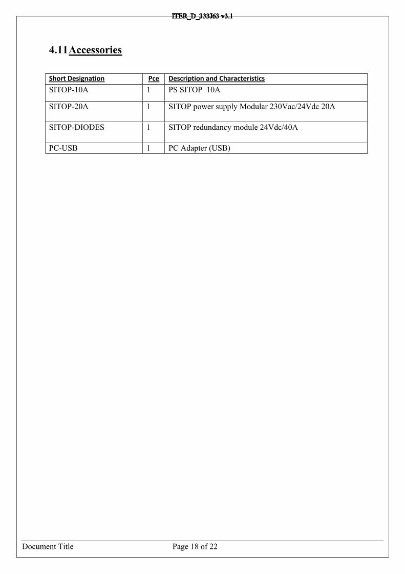
4.11Accessories
Short Designation Pce Description and Characteristics
SITOP-10A 1 PS SITOP 10A
SITOP-20A 1 SITOP power supply Modular 230Vac/24Vdc 20A
SITOP-DIODES 1 SITOP redundancy module 24Vdc/40A
PC-USB 1 PC Adapter (USB)

Document Title Page 19 of 22
5 NetworksTBD

Document Title Page 20 of 22
6 Cubicle Monitoring System
Short Designation Pce Description and Characteristics
CPU1214C 1 CPU 1214C 14 DI, 10 DO, 2AI
PS1200-2.5A 2 S7-1200 POWER MODUL PM1207 2.5 A
Document Title Page 21 of 22
7 Software Packages
The table below represents the software packages required to program PLCs on the ITER projects. Depending on the type of applications, different sets of packages are required.
- Basic Package: Step 7 + PLCSIM + SCL + S7-Graph + CFC.- Fail Safe applications with SIL>=2: Basic Package + all “F Systems” packages.- S7-1200 applications: TIA Portal
The Safety Matrix is an optional feature not required in any cases.
Short Designation Description Latest Version
Dependency
Step 7 SIMATIC Manager with Ladder, Functional Block Diagram, List editors.
V5.5 -
TIA portal Totally Integrated Automation portal. The successor of Step 7. Simulator is integrated.
V11.0 -
PLCSIM Step 7 Application Simulator. Integrated in the Step 7 professional package.
V5.4 Step 7
SCL Structured Text Editor. Higher level programming. Related to PASCAL structured language.
V5.3 Step 7
S7-Graph Grafcet Editor V5.3 Step 7CFC Continuous Flow Chart V7.1 Step 7“F” Configuration Pack
Module required to program Fail Safe systems
V5.5 Step 7
“F” Systems Module required to program Fail Safe systems
V6.1 Step 7
“F” Systems Library
Module required to program Fail Safe systems
V1.3 Step 7
Safety Matrix Safety Matrix Editor. It is an additional abstraction layer for CFC. Purpose is to program safety functions with a visual cause/effect matrix.
V6.2 CFC, “F” Systems

Document Title Page 22 of 22
8 Annexe: Siemens Reference List.
Pointer to Reference Document: [RD 1]
Figure 6 – Schema of PCDH documents


![arXiv:1705.08041v2 [cs.CV] 18 Dec 2018 · iter iter iter iter Single Iteration: CNN Prior Figure 1: A proximal gradient ODP network for deblurring under Gaussian noise, mapping the](https://static.fdocuments.in/doc/165x107/5f39be22f6fe290b831f0c4a/arxiv170508041v2-cscv-18-dec-2018-iter-iter-iter-iter-single-iteration-cnn.jpg)


