
ITER diagnostics progress G. Vayakis for the ITER...
66
G. Vayakis, ITER progress, ITPA 26, Pohang Page 1 ITER diagnostics progress G. Vayakis for the ITER diagnostic team ITPA 26, Pohang
Transcript of ITER diagnostics progress G. Vayakis for the ITER...
G. Vayakis, ITER progress, ITPA 26, Pohang Page 1
ITER diagnostics progress
G. Vayakis for the ITER diagnostic team
ITPA 26, Pohang
G. Vayakis, ITER progress, ITPA 26, Pohang Page 2
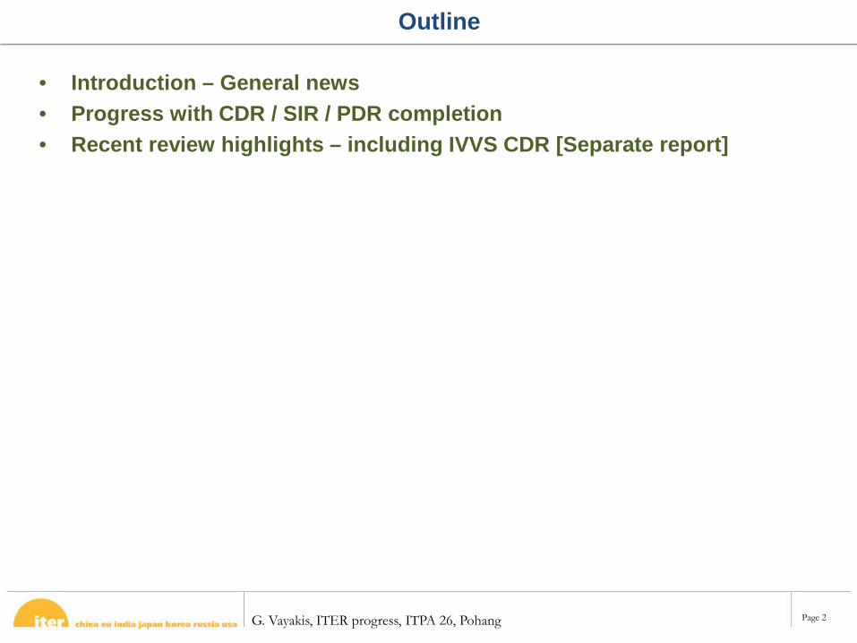
Outline
• Introduction – General news• Progress with CDR / SIR / PDR completion• Recent review highlights – including IVVS CDR [Separate report]
G. Vayakis, ITER progress, ITPA 26, Pohang Page 3
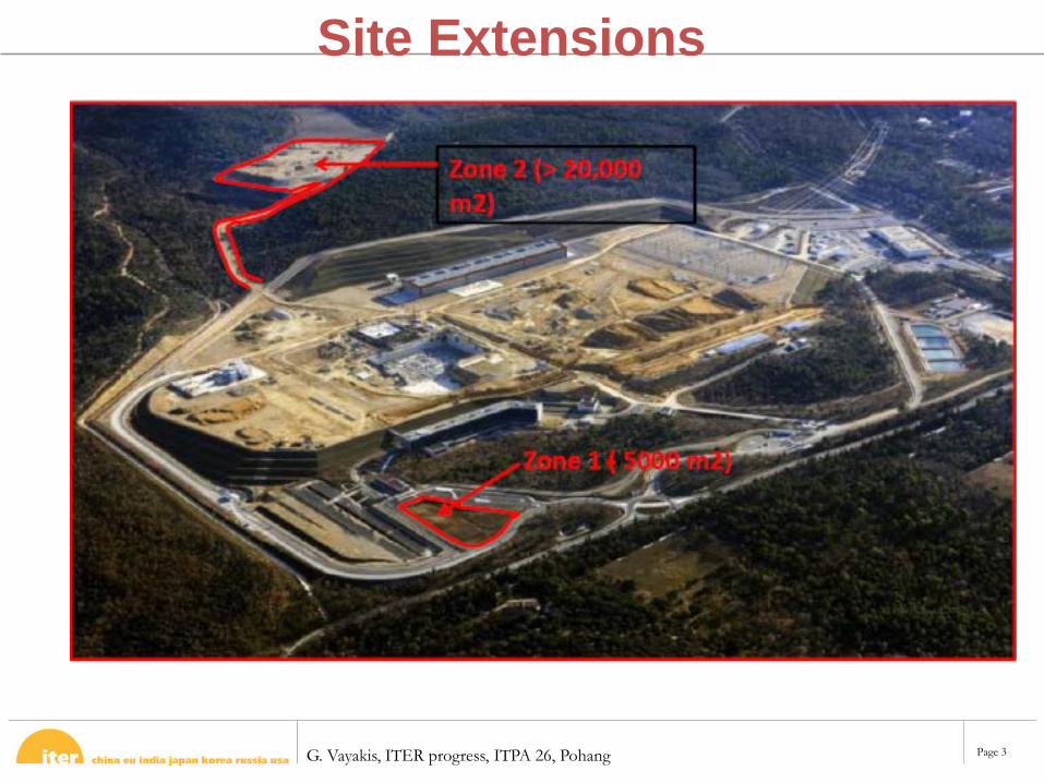
Site Extensions
G. Vayakis, ITER progress, ITPA 26, Pohang Page 4
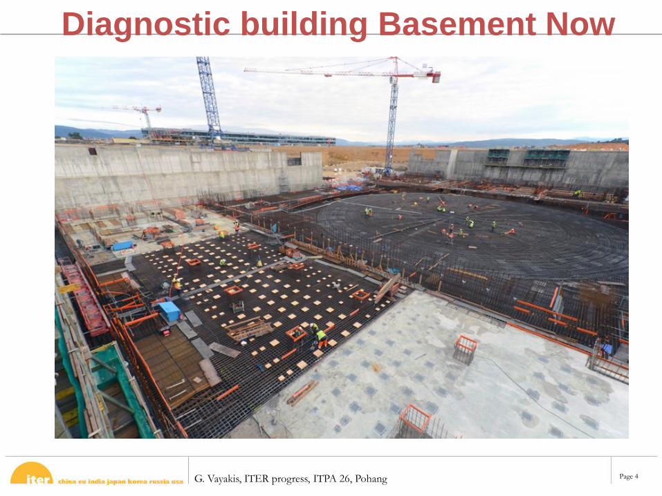
Diagnostic building Basement Now
G. Vayakis, ITER progress, ITPA 26, Pohang Page 5
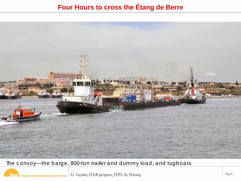
Four Hours to cross the Étang de Berre
The convoy—the barge, 800-ton trailer and dummy load, and tugboats
G. Vayakis, ITER progress, ITPA 26, Pohang Page 6
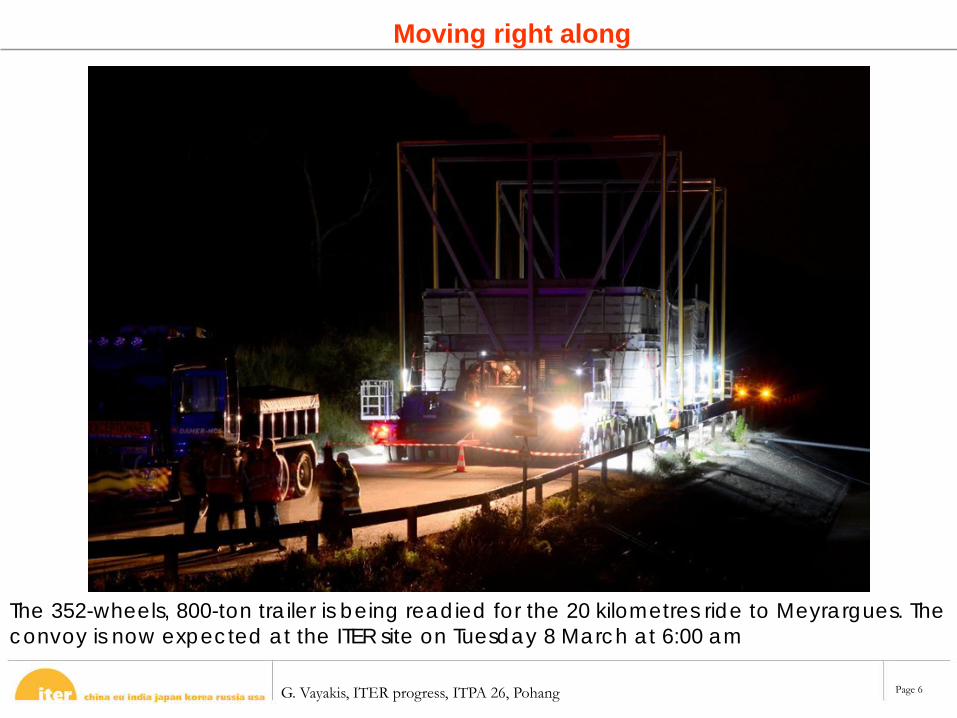
Moving right along
The 352-wheels, 800-ton trailer is being readied for the 20 kilometres ride to Meyrargues. The convoy is now expected at the ITER site on Tuesday 8 March at 6:00 am
G. Vayakis, ITER progress, ITPA 26, Pohang Page 7
Diagnostics comments / news
• IVVS is now with IO !!!• Diagnostics start to be in procurement (F4E call for
tender for CER published this week)• In PDR/FDR phase, diagnostic system reviews will
fragment and concentrate much more on engineering– Example: Microfission chamber PDR part 1 on cabling
• In future, work on requirements will probably be– Specific corrections / modifications to PR/SRD chain as
diagnostic design becomes clearer– Inetgrated reviews of performance (perhaps through
PCS/POP)• Interfaces are an increasingly strong driver
G. Vayakis, ITER progress, ITPA 26, Pohang Page 8
Interfaces
• Building and Machine are very interconnected• Machine and Diagnostics are very interconnected• Diagnostics and Diagnostics are very interconnected• Our equipment is all over the plans – can’t ignore
Many interfaces already frozen (all in buildings)
Many more will need to be frozen to allow progress!
Everybody has been and will continue to be under pressure to lock these down……..
G. Vayakis, ITER progress, ITPA 26, Pohang Page 9
Port Integration Activities
PCSS
ISS
PP
Rails
BioshieldInner Outer
GRS reservation
LFS H alpha
LENPA
Cryostat
RGA
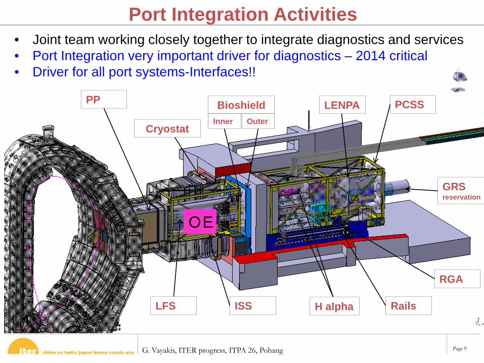
• Joint team working closely together to integrate diagnostics and services• Port Integration very important driver for diagnostics – 2014 critical• Driver for all port systems-Interfaces!!
OE
G. Vayakis, ITER progress, ITPA 26, Pohang Page 10
Interfaces and Design Reviews
• CDR, FDR and PDR etc. are not tied to interfaces needs.• Interfaces are done in passes usually (see later)• Say Pass-0, Pass-1, Pass-final
E.g. Divertor needs Pass-1 for all Divertor Diagnostics in June 2014 and Pass-Final in May 2016
Design Teams need to respond to these needs• Integrator will usually need the latter – you need the former.
We mustn’t forget diagrams and will be needed outside of DR planned dates!!!!!!!!
G. Vayakis, ITER progress, ITPA 26, Pohang Page 11
Other examples of interface freezing
• Blanket• Divertor
G. Vayakis, ITER progress, ITPA 26, Pohang Page 12
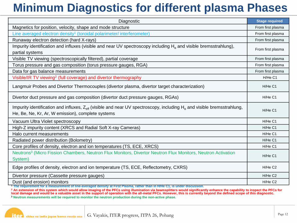
Minimum Diagnostics for different plasma Phases
1 The requirement for a measurement of line-averaged density at First Plasma, rather than in H/He C1, is under discussion.2 An extension of this system which would allow imaging of the PFCs using illumination via beamsplitters would significantly enhance the capability to inspect the PFCs for local damage and would be a valuable asset in the support of operation with the all-metal PFCs. However, this is currently beyond the defined scope of this diagnostic.3 Neutron measurements will be required to monitor the neutron production during the non-active phase.
Diagnostic Stage requiredMagnetics for position, velocity, shape and mode structure From first plasma
Line averaged electron density1 (toroidal polarimeter/ interferometer) From first plasma
Runaway electron detection (hard X-rays) From first plasma
Impurity identification and influxes (visible and near UV spectroscopy including Hα and visible bremsstrahlung), partial systems
From first plasma
Visible TV viewing (spectroscopically filtered), partial coverage From first plasma
Torus pressure and gas composition (torus pressure gauges, RGA) From first plasma
Data for gas balance measurements From first plasma
Visible/IR TV viewing2 (full coverage) and divertor thermography H/He C1
Langmuir Probes and Divertor Thermocouples (divertor plasma, divertor target characterization) H/He C1
Divertor duct pressure and gas composition (divertor duct pressure gauges, RGAs) H/He C1
Impurity identification and influxes, Zeff (visible and near UV spectroscopy, including Hα and visible bremsstrahlung, He, Be, Ne, Kr, Ar, W emission), complete systems
H/He C1
Vacuum Ultra Violet spectroscopy H/He C1
High-Z impurity content (XRCS and Radial Soft X-ray Cameras) H/He C1
Halo current measurements H/He C1
Radiated power distribution (Bolometry) H/He C1
Core profiles of density, electron and ion temperatures (TS, ECE, XRCS) H/He C1
Neutrons3 (Micro Fission Chambers, Neutron Flux Monitors, Divertor Neutron Flux Monitors, Neutron Activation System)
H/He C1
Edge profiles of density, electron and ion temperature (TS, ECE, Reflectometry, CXRS) H/He C2
Divertor pressure (Cassette pressure gauges) H/He C2
Dust (and erosion) monitors H/He C2
G. Vayakis, ITER progress, ITPA 26, Pohang Page 13
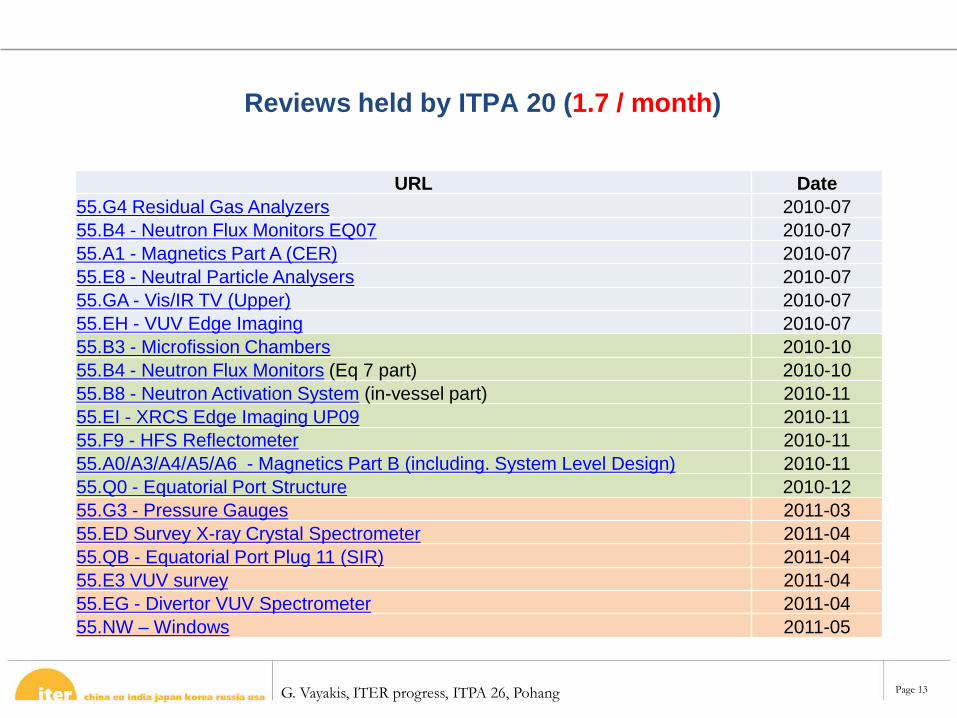
Reviews held by ITPA 20 (1.7 / month)
URL Date55.G4 Residual Gas Analyzers 2010-0755.B4 - Neutron Flux Monitors EQ07 2010-0755.A1 - Magnetics Part A (CER) 2010-0755.E8 - Neutral Particle Analysers 2010-0755.GA - Vis/IR TV (Upper) 2010-0755.EH - VUV Edge Imaging 2010-0755.B3 - Microfission Chambers 2010-1055.B4 - Neutron Flux Monitors (Eq 7 part) 2010-1055.B8 - Neutron Activation System (in-vessel part) 2010-1155.EI - XRCS Edge Imaging UP09 2010-1155.F9 - HFS Reflectometer 2010-1155.A0/A3/A4/A5/A6 - Magnetics Part B (including. System Level Design) 2010-1155.Q0 - Equatorial Port Structure 2010-1255.G3 - Pressure Gauges 2011-0355.ED Survey X-ray Crystal Spectrometer 2011-0455.QB - Equatorial Port Plug 11 (SIR) 2011-0455.E3 VUV survey 2011-0455.EG - Divertor VUV Spectrometer 2011-0455.NW – Windows 2011-05
G. Vayakis, ITER progress, ITPA 26, Pohang Page 14
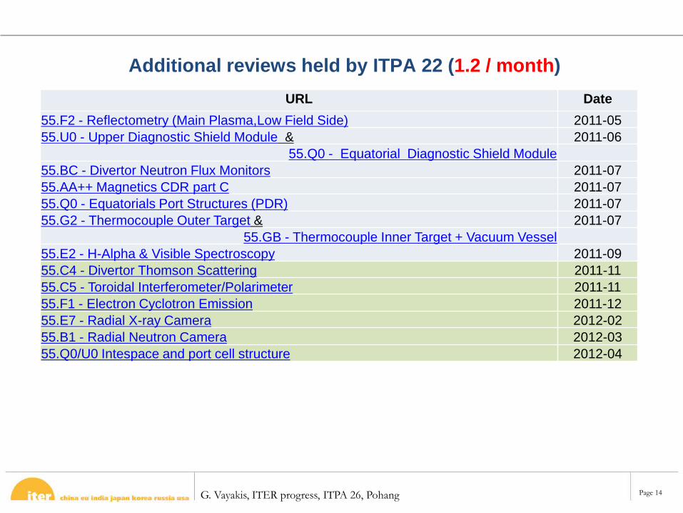
Additional reviews held by ITPA 22 (1.2 / month)URL Date
55.F2 - Reflectometry (Main Plasma,Low Field Side) 2011-0555.U0 - Upper Diagnostic Shield Module & 2011-06
55.Q0 - Equatorial Diagnostic Shield Module55.BC - Divertor Neutron Flux Monitors 2011-0755.AA++ Magnetics CDR part C 2011-0755.Q0 - Equatorials Port Structures (PDR) 2011-0755.G2 - Thermocouple Outer Target & 2011-07
55.GB - Thermocouple Inner Target + Vacuum Vessel55.E2 - H-Alpha & Visible Spectroscopy 2011-0955.C4 - Divertor Thomson Scattering 2011-1155.C5 - Toroidal Interferometer/Polarimeter 2011-1155.F1 - Electron Cyclotron Emission 2011-1255.E7 - Radial X-ray Camera 2012-0255.B1 - Radial Neutron Camera 2012-0355.Q0/U0 Intespace and port cell structure 2012-04
G. Vayakis, ITER progress, ITPA 26, Pohang Page 15
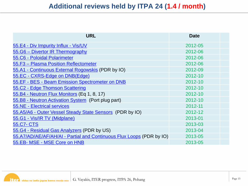
Additional reviews held by ITPA 24 (1.4 / month)
URL Date
55.E4 - Div Impurity Influx - Vis/UV 2012-0555.G6 – Divertor IR Thermography 2012-0655.C6 - Poloidal Polarimeter 2012-0655.F3 – Plasma Position Reflectometer 2012-0655.A1 - Continuous External Rogowskis (PDR by IO) 2012-0955.EC - CXRS-Edge on DNB(Edge) 2012-1055.EF - BES - Beam Emission Spectrometer on DNB 2012-1055.C2 - Edge Thomson Scattering 2012-1055.B4 - Neutron Flux Monitors (Eq 1, 8, 17) 2012-1055.B8 - Neutron Activation System (Port plug part) 2012-1055.NE - Electrical services 2012-1155.A5/A6 - Outer Vessel Steady State Sensors (PDR by IO) 2012-1255.G1 - Vis/IR TV (Midplane) 2013-0155.C7- CTS 2013-0355.G4 - Residual Gas Analyzers (PDR by US) 2013-0455.A7/AD/AE/AF/AH/AI - Partial and Continuous Flux Loops (PDR by IO) 2013-0555.EB- MSE - MSE Core on HNB 2013-05
G. Vayakis, ITER progress, ITPA 26, Pohang Page 16
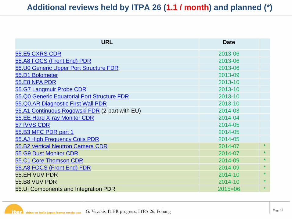
Additional reviews held by ITPA 26 (1.1 / month) and planned (*)
URL Date
55.E5 CXRS CDR 2013-0655.A8 FOCS (Front End) PDR 2013-0655.U0 Generic Upper Port Structure FDR 2013-0655.D1 Bolometer 2013-0955.E8 NPA PDR 2013-1055.G7 Langmuir Probe CDR 2013-1055.Q0 Generic Equatorial Port Structure FDR 2013-1055.Q0.AR Diagnostic First Wall PDR 2013-1055.A1 Continuous Rogowski FDR (2-part with EU) 2014-0355.EE Hard X-ray Monitor CDR 2014-0457 IVVS CDR 2014-0555.B3 MFC PDR part 1 2014-0555.AJ High Frequency Coils PDR 2014-0555.B2 Vertical Neutron Camera CDR 2014-07 *55.G9 Dust Monitor CDR 2014-07 *55.C1 Core Thomson CDR 2014-09 *55.A8 FOCS (Front End) FDR 2014-09 *55.EH VUV PDR 2014-10 *55.B8 VUV PDR 2014-10 *55.UI Components and Integration PDR 2015=06 *
G. Vayakis, ITER progress, ITPA 26, Pohang Page 17
Overview - Progress
• 47 Diagnostic Systems through Various levels of Design Review
Equates to over 80% of CDRs completed Several PDRs now complete and many coming this year 4 FDRs carried out
• 36 Diagnostic or Support Systems Annex B’s signed Significant resource now building up in all DAs
• Cost is a big driver Sharing similar work by forming joint-design teams and common
procurements This helps to manage the costs better
G. Vayakis, ITER progress, ITPA 26, Pohang Page 18
Equatorial and Upper Port Plug Design Update: post-FDR
V.S. Udintsev, P. Maquet, S. Pak, M. Portales, C. Vacas, M. Proust, T. Giacomin and all other contributors
G. Vayakis, ITER progress, ITPA 26, Pohang Page 19
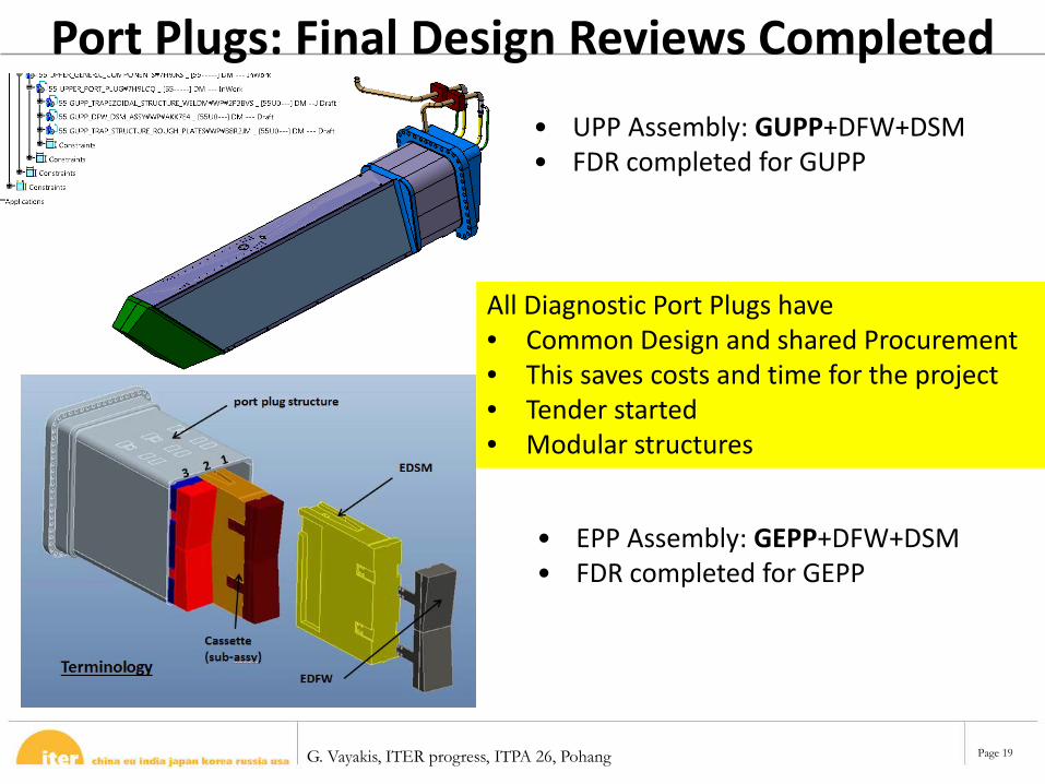
Port Plugs: Final Design Reviews Completed• UPP Assembly: GUPP+DFW+DSM• FDR completed for GUPP
• EPP Assembly: GEPP+DFW+DSM• FDR completed for GEPP
All Diagnostic Port Plugs have • Common Design and shared Procurement• This saves costs and time for the project• Tender started• Modular structures
G. Vayakis, ITER progress, ITPA 26, Pohang Page 20
Introduction / Summary
- Basic features of the Equatorial/Upper Port Plug unchanged
- Final dimensions of structure and DSM based on the gap configurations.
- Several configurations being analyzed to meet both neutronics and assembly requirements.
- Evolutions of design being incorporated before starting all the analysis (DSM rails, DSM labyrinths, sliding pads on the bottom, gripping point, DFW fixation, Shim plates, Additional hydraulic connections).
- EQ/UP Port Plug Structure FDR Schedule
- Interface specifications being updated
- Generic works (feedthrough, handling cover plate, backing jacket, thermocouples)
G. Vayakis, ITER progress, ITPA 26, Pohang Page 21
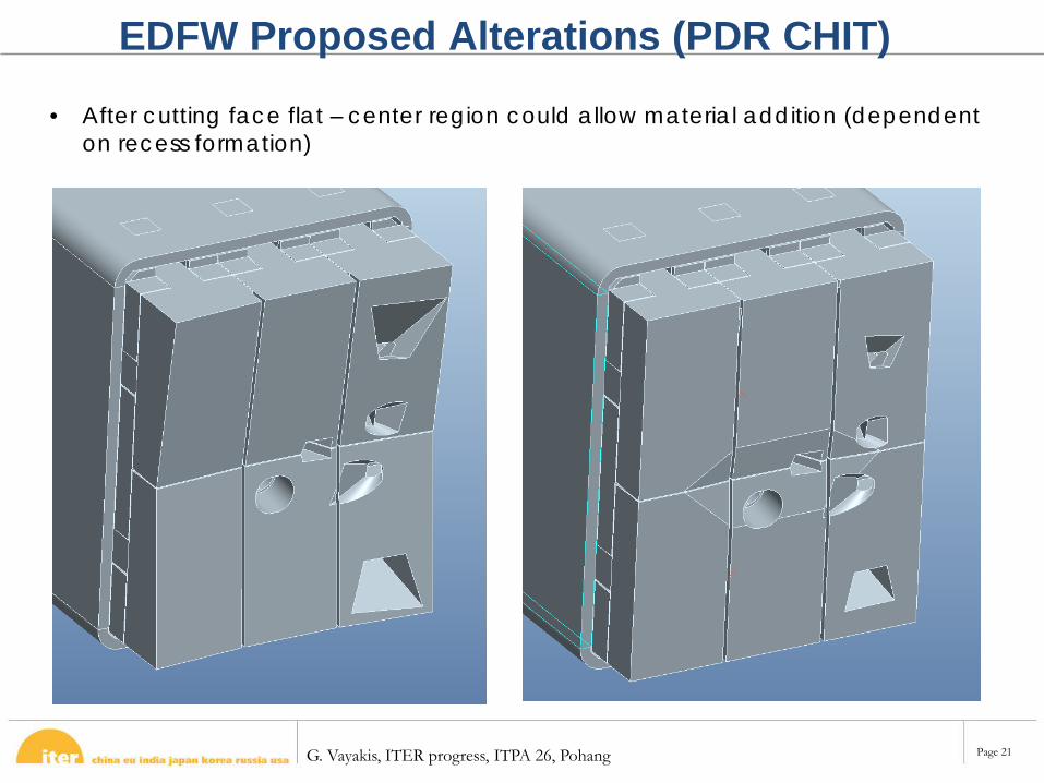
EDFW Proposed Alterations (PDR CHIT)
• After cutting face flat – center region could allow material addition (dependent on recess formation)
G. Vayakis, ITER progress, ITPA 26, Pohang Page 22
DFW PDR- Successfully passed in December 2013- Plans for Generic DFW FDR in
December 2014- Then, “light”-FDRs for each port
G. Vayakis, ITER progress, ITPA 26, Pohang Page 23
“C”
“C”
“C”
“C”
“C”
“C”
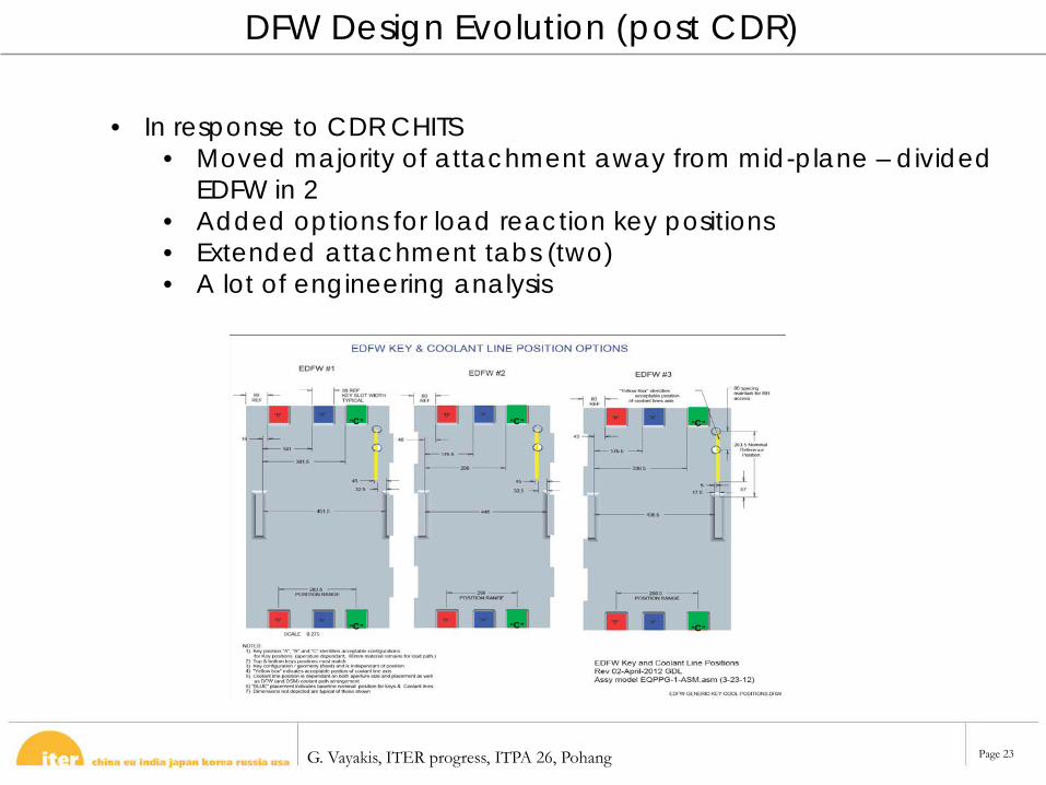
DFW Design Evolution (post CDR)
• In response to CDR CHITS • Moved majority of attachment away from mid-plane – divided
EDFW in 2 • Added options for load reaction key positions• Extended attachment tabs (two)• A lot of engineering analysis
G. Vayakis, ITER progress, ITPA 26, Pohang Page 24
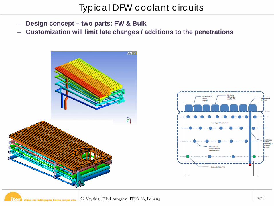
– Design concept – two parts: FW & Bulk– Customization will limit late changes / additions to the penetrations
Typical DFW coolant circuits
G. Vayakis, ITER progress, ITPA 26, Pohang Page 25
NEUTRON CALIBRATION UPDATE
G. Vayakis, ITER progress, ITPA 26, Pohang Page 26
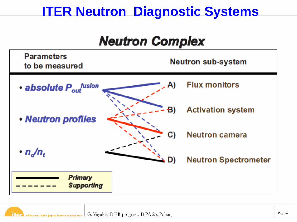
ITER Neutron Diagnostic Systems
G. Vayakis, ITER progress, ITPA 26, Pohang Page 27
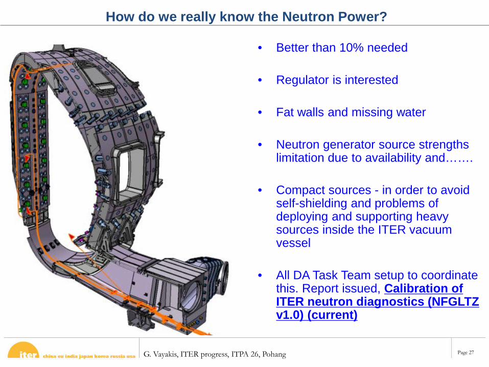
• Better than 10% needed
• Regulator is interested
• Fat walls and missing water
• Neutron generator source strengths limitation due to availability and…….
• Compact sources - in order to avoid self-shielding and problems of deploying and supporting heavy sources inside the ITER vacuum vessel
• All DA Task Team setup to coordinate this. Report issued, Calibration of ITER neutron diagnostics (NFGLTZ v1.0) (current)
How do we really know the Neutron Power?
G. Vayakis, ITER progress, ITPA 26, Pohang Page 28
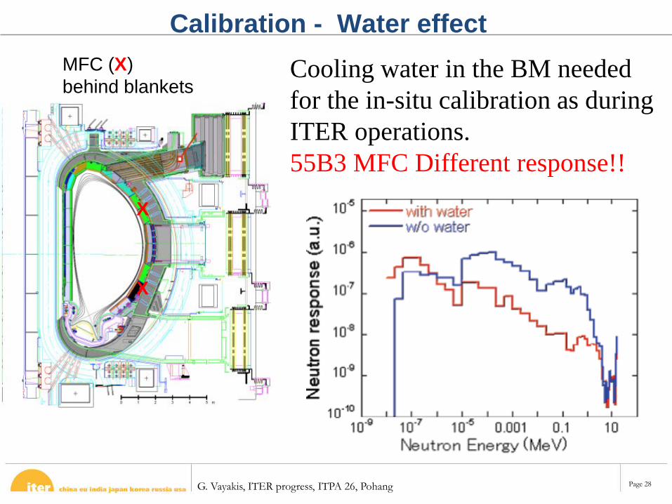
Calibration - Water effectCooling water in the BM needed for the in-situ calibration as during ITER operations. 55B3 MFC Different response!!
MFC (X)behind blankets
X
X
G. Vayakis, ITER progress, ITPA 26, Pohang Page 29
BOLOMETRY - CABLING
G. Vayakis, ITER progress, ITPA 26, Pohang Page 30
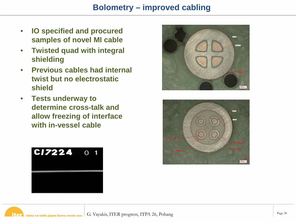
Bolometry – improved cabling
• IO specified and procured samples of novel MI cable
• Twisted quad with integral shielding
• Previous cables had internal twist but no electrostatic shield
• Tests underway to determine cross-talk and allow freezing of interface with in-vessel cable
G. Vayakis, ITER progress, ITPA 26, Pohang Page 31
LANGMUIR PROBE CDR
G. Vayakis, ITER progress, ITPA 26, Pohang Page 32
Thanks!
• … to CNDA, especially– Zhao Wei, Guangwu Zhang
• … to IO Diagnostics & POP, especially– Philip, George, Victor, Natalia (and Alex), Ciprian, Richard, Martin Kocan
• … to CEA, i.e. Jamie Gunn• … external panel members
– Albrecht Herrmann, Michael Faux, Suk-Ho Hong
G. Vayakis, ITER progress, ITPA 26, Pohang Page 33
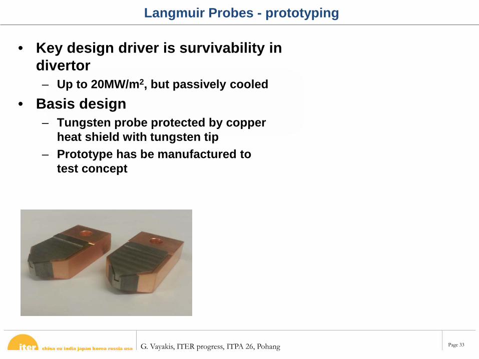
Langmuir Probes - prototyping
• Key design driver is survivability in divertor– Up to 20MW/m2, but passively cooled
• Basis design– Tungsten probe protected by copper
heat shield with tungsten tip– Prototype has be manufactured to
test concept
G. Vayakis, ITER progress, ITPA 26, Pohang Page 34
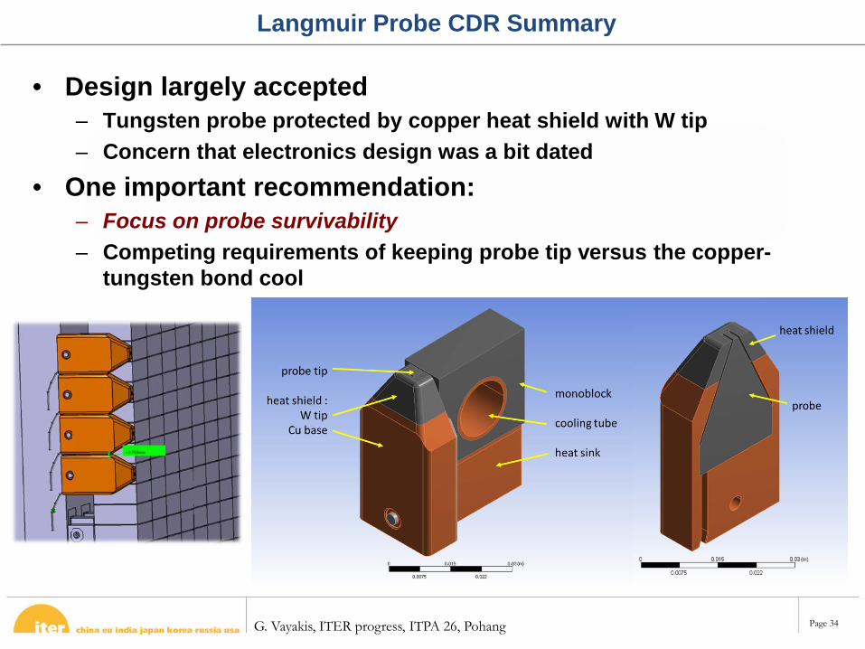
Langmuir Probe CDR Summary
• Design largely accepted– Tungsten probe protected by copper heat shield with W tip– Concern that electronics design was a bit dated
• One important recommendation:– Focus on probe survivability– Competing requirements of keeping probe tip versus the copper-
tungsten bond cool
G. Vayakis, ITER progress, ITPA 26, Pohang Page 35
PA Prognosis
• CDR is now closed, with all Cat 1 chits solved• PA is on track, with signature expected in July
G. Vayakis, ITER progress, ITPA 26, Pohang Page 36
Probe CDR Results
• Chits (nicely) grouped by topic– Time resolution, Spatial resolution, Accuracy, Thermal load,
Waste managing, Parameters and real time data analysis Electronics/CODAC, Risk and reliability, Others
• Seven Cat 1 Chits– 3 related to measurement requirements/specifications– 2 related to design issues/improvements– 1 related to loads– 1 administrative
• 20 Cat 2 and 3
G. Vayakis, ITER progress, ITPA 26, Pohang Page 37
NPA PDR outcomes
JM Drevon, R O’Connor, V Martin

G. Vayakis, ITER progress, ITPA 26, Pohang Page 38
• Organized on the 22nd and 23rd of October by the RFDA with the help of the IO. Two levels: PDR of the NPA and review of GRS Concept
• 7 “category 1” chits, 20 “category 2” chits and 8 “category 3” chits:
• 1 cat. 1 chit on the GRS design• 3 cat. 1 chits on the NPA design• 3 cat. 1 chits on the documentation:
Remote handling compatibility assessment (RHCA) missing Update DDD with final decision on aperture and pitch angle Update DR documentation taking into account the IDM reviewers comments
NPA PDR outcomes
G. Vayakis, ITER progress, ITPA 26, Pohang Page 39
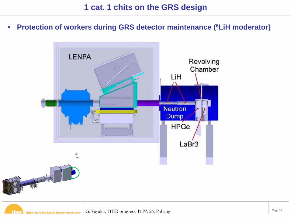
• Protection of workers during GRS detector maintenance (6LiH moderator)
1 cat. 1 chits on the GRS design
G. Vayakis, ITER progress, ITPA 26, Pohang Page 40
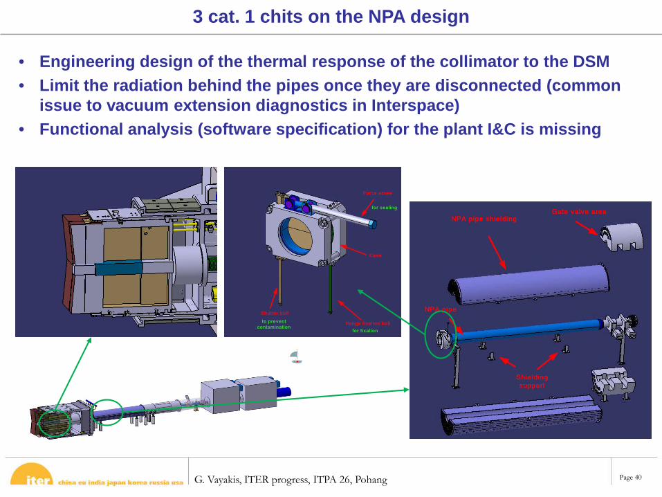
• Engineering design of the thermal response of the collimator to the DSM• Limit the radiation behind the pipes once they are disconnected (common
issue to vacuum extension diagnostics in Interspace)• Functional analysis (software specification) for the plant I&C is missing
3 cat. 1 chits on the NPA design
G. Vayakis, ITER progress, ITPA 26, Pohang Page 41
• The review panel acknowledges the effort and progress made by the DA since the CDR held in 2010
• NPA design too much in advance compare to its neighbor -> schedule to be harmonized with EP#11 tenants
• A PCR is going to be risen to include the GRS in the NPA package
• Too much documents in the input package: huge work for administration, quite impossible for the panel to read it all => advise is relying mainly on presentations. To gathered them by topics in a few merged documents?
• Many thanks to all IO people who helps during the preparation
General comments
G. Vayakis, ITER progress, ITPA 26, Pohang Page 43
ITER System Level Requirements of HF Sensors
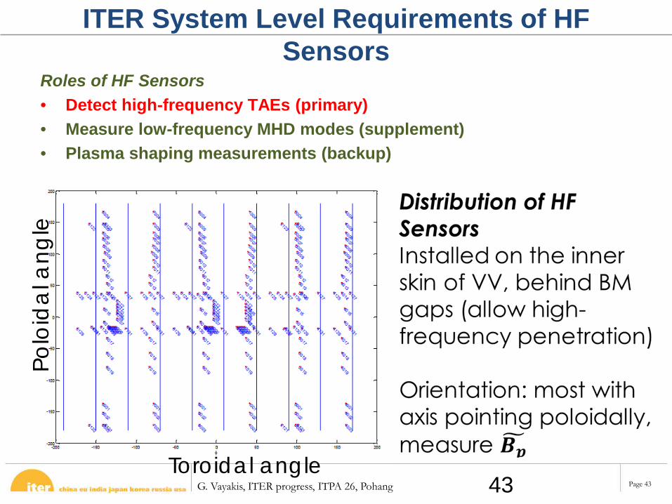
Roles of HF Sensors • Detect high-frequency TAEs (primary) • Measure low-frequency MHD modes (supplement)• Plasma shaping measurements (backup)
Toroidal angle
Polo
ida
l ang
le
43
G. Vayakis, ITER progress, ITPA 26, Pohang Page 44
ITER high-frequency magnetic sensor
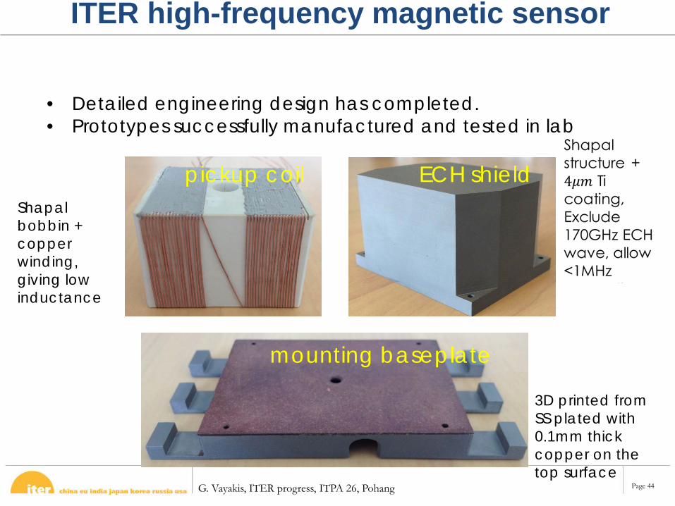
• Detailed engineering design has completed. • Prototypes successfully manufactured and tested in lab
pickup coil ECH shield
mounting baseplate
Shapal bobbin + copper winding,giving low inductance
3D printed from SS plated with 0.1mm thick copper on the top surface
G. Vayakis, ITER progress, ITPA 26, Pohang Page 45
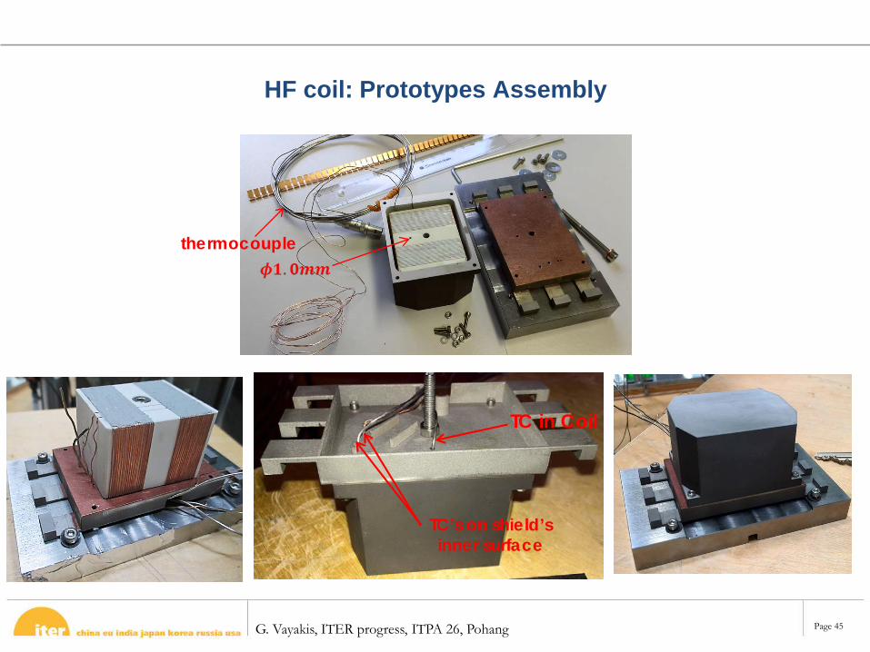
HF coil: Prototypes Assembly
TC in Coil
TC’s on shield’s inner surface
thermocouple
G. Vayakis, ITER progress, ITPA 26, Pohang Page 46
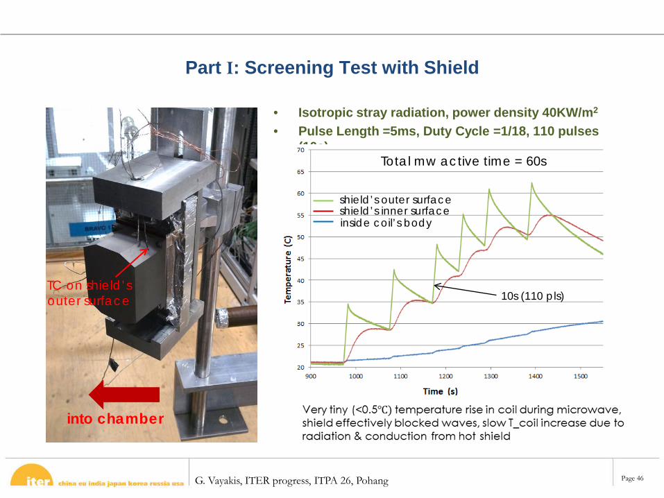
Part I: Screening Test with Shield
• Isotropic stray radiation, power density 40KW/m2
• Pulse Length =5ms, Duty Cycle =1/18, 110 pulses (10s)
into chamber
TC on shield’s outer surface 10s (110 pls)
shield’s outer surfaceshield’s inner surfaceinside coil’s body
Total mw active time = 60s
G. Vayakis, ITER progress, ITPA 26, Pohang Page 47
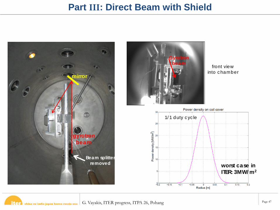
mirror
gyrotron beam
Beam splitter removed
Gyrotron beam
front view into chamber
worst case in ITER: 3MW/m2
1/1 duty cycle
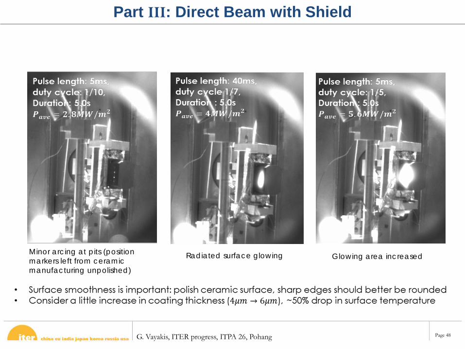
Part III: Direct Beam with Shield
G. Vayakis, ITER progress, ITPA 26, Pohang Page 48
Minor arcing at pits (position markers left from ceramic manufacturing unpolished)
Radiated surface glowing Glowing area increased
Part III: Direct Beam with Shield
G. Vayakis, ITER progress, ITPA 26, Pohang Page 49
CDR of HXRM
G. Jagannathan1, R. Barnsley1, S. Pandya2, K. Assudani2 and R. Makwana2
1ITER Organization, France2Institute for Plasma Research, India
G. Vayakis, ITER progress, ITPA 26, Pohang Page 50
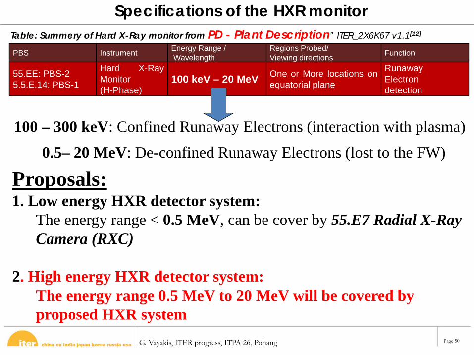
PBS Instrument Energy Range /Wavelength
Regions Probed/Viewing directions Function
55.EE: PBS-25.5.E.14: PBS-1
Hard X-RayMonitor(H-Phase)
100 keV – 20 MeV One or More locations onequatorial plane
RunawayElectrondetection
Table: Summery of Hard X-Ray monitor from PD - Plant Description” ITER_2X6K67 v1.1[12]
Specifications of the HXR monitor
100 – 300 keV: Confined Runaway Electrons (interaction with plasma)0.5– 20 MeV: De-confined Runaway Electrons (lost to the FW)
Proposals:1. Low energy HXR detector system:
The energy range < 0.5 MeV, can be cover by 55.E7 Radial X-Ray Camera (RXC)
2. High energy HXR detector system: The energy range 0.5 MeV to 20 MeV will be covered by proposed HXR system
G. Vayakis, ITER progress, ITPA 26, Pohang Page 51
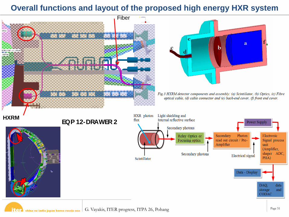
Overall functions and layout of the proposed high energy HXR system
EQP 12-DRAWER 2HXRM
Fiber
G. Vayakis, ITER progress, ITPA 26, Pohang Page 52
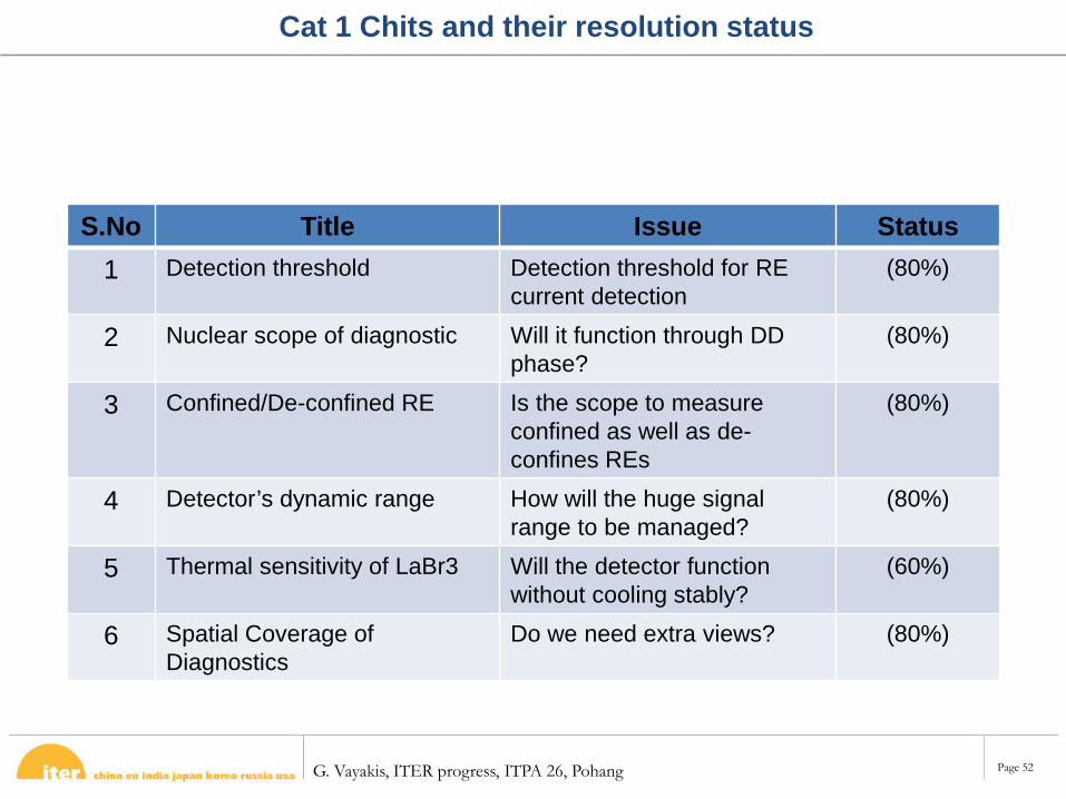
Cat 1 Chits and their resolution status
S.No Title Issue Status1 Detection threshold Detection threshold for RE
current detection(80%)
2 Nuclear scope of diagnostic Will it function through DD phase?
(80%)
3 Confined/De-confined RE Is the scope to measure confined as well as de-confines REs
(80%)
4 Detector’s dynamic range How will the huge signal range to be managed?
(80%)
5 Thermal sensitivity of LaBr3 Will the detector function without cooling stably?
(60%)
6 Spatial Coverage of Diagnostics
Do we need extra views? (80%)
G. Vayakis, ITER progress, ITPA 26, Pohang Page 53
Summary of IVVS CDR 13/14 May 2014R. Reichle
IO Diagnostics V. Martin (Secretary), A. Suarez, N. Casal, F. Leipold, G. Passedat, Ch. Walker, Ph. Morgan, M. Kocan, M. Walsh, J. Ferreol, H.P. Marti, R. Bouhamou + Diagnostics team
IO InterfacesJ. Palmer, O. Bede, S. Lisgo, R. Pitts, G. Vitupier, S. Rosanvallon, M. Shute and many others
F4E RHC. Damiani, A. Puiu, G. Dubus, Ph. Bates, R. Pampin
ENEA teamC. Neri, P. Rosso, M. Ferro de Colibus and team
OTL team
CDR Chairman: P. StottTechnical Experts: Ph. Prior, S. Vives, R. Chavan, J.S. Sabban, A. Ibarra, A. Herrmann, A. Kaye, G. DeTemmermann,
G. Vayakis, ITER progress, ITPA 26, Pohang Page 54
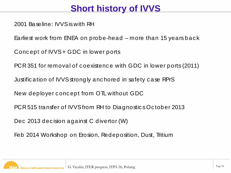
Short history of IVVS2001 Baseline: IVVS is with RH
Earliest work from ENEA on probe-head – more than 15 years back
Concept of IVVS + GDC in lower ports
PCR 351 for removal of coexistence with GDC in lower ports (2011)
Justification of IVVS strongly anchored in safety case RPrS
New deployer concept from OTL without GDC
PCR 515 transfer of IVVS from RH to Diagnostics October 2013
Dec 2013 decision against C divertor (W)
Feb 2014 Workshop on Erosion, Redeposition, Dust, Tritium
G. Vayakis, ITER progress, ITPA 26, Pohang Page 55
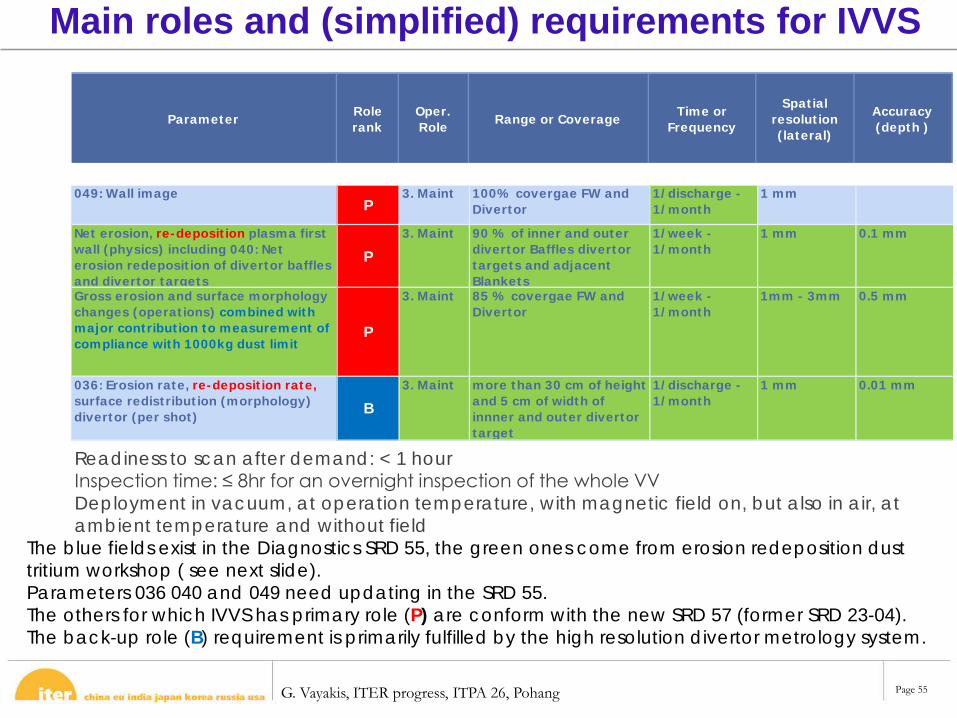
Main roles and (simplified) requirements for IVVS
Parameter Role rank
Oper. Role Range or Coverage Time or
Frequency
Spatial resolution (lateral)
Accuracy (depth )
049: Wall imageP
3. Maint 100% covergae FW and Divertor
1/discharge - 1/month
1 mm
Net erosion, re-deposition plasma first wall (physics) including 040: Net erosion redeposition of divertor baffles and divertor targets
P3. Maint 90 % of inner and outer
divertor Baffles divertor targets and adjacent Blankets
1/week - 1/month
1 mm 0.1 mm
Gross erosion and surface morphology changes (operations) combined with major contribution to measurement of compliance with 1000kg dust limit
P
3. Maint 85 % covergae FW and Divertor
1/week - 1/month
1mm - 3mm 0.5 mm
036: Erosion rate, re-deposition rate, surface redistribution (morphology) divertor (per shot) B
3. Maint more than 30 cm of height and 5 cm of width of innner and outer divertor target
1/discharge - 1/month
1 mm 0.01 mm
Readiness to scan after demand: < 1 hourInspection time: ≤ 8hr for an overnight inspection of the whole VVDeployment in vacuum, at operation temperature, with magnetic field on, but also in air, at ambient temperature and without field
The blue fields exist in the Diagnostics SRD 55, the green ones come from erosion redeposition dust tritium workshop ( see next slide).Parameters 036 040 and 049 need updating in the SRD 55.The others for which IVVS has primary role (P) are conform with the new SRD 57 (former SRD 23-04).The back-up role (B) requirement is primarily fulfilled by the high resolution divertor metrology system.
G. Vayakis, ITER progress, ITPA 26, Pohang Page 58
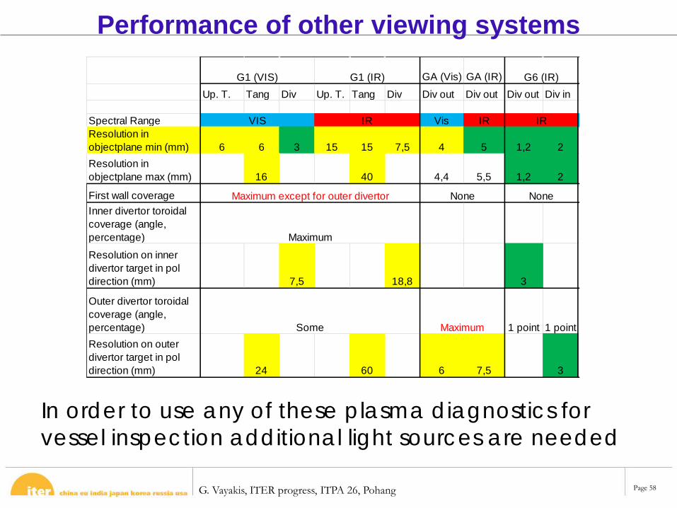
GA (Vis) GA (IR)Up. T. Tang Div Up. T. Tang Div Div out Div out Div out Div in
Spectral Range Vis IRResolution in objectplane min (mm) 6 6 3 15 15 7,5 4 5 1,2 2Resolution in objectplane max (mm) 16 40 4,4 5,5 1,2 2
First wall coverageInner divertor toroidal coverage (angle, percentage) Resolution on inner divertor target in pol direction (mm) 7,5 18,8 3
Outer divertor toroidal coverage (angle, percentage) 1 point 1 pointResolution on outer divertor target in pol direction (mm) 24 60 6 7,5 3
None
G6 (IR)
VIS IR IR
Maximum except for outer divertor
Maximum
Maximum
Some
G1 (VIS) G1 (IR)
None
Performance of other viewing systems
In order to use any of these plasma diagnostics for vessel inspection additional light sources are needed
G. Vayakis, ITER progress, ITPA 26, Pohang Page 59
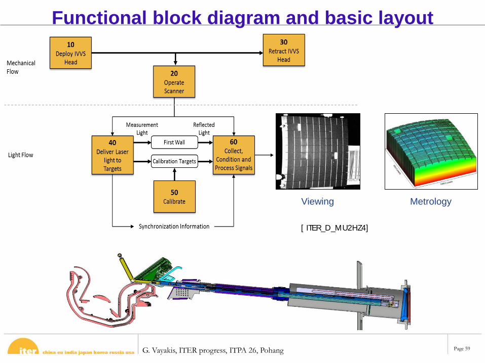
Functional block diagram and basic layout
[ ITER_D_MU2HZ4]
Viewing Metrology
G. Vayakis, ITER progress, ITPA 26, Pohang Page 60
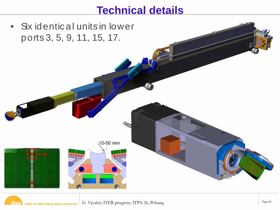
Technical details• Six identical units in lower
ports 3, 5, 9, 11, 15, 17.
G. Vayakis, ITER progress, ITPA 26, Pohang Page 61
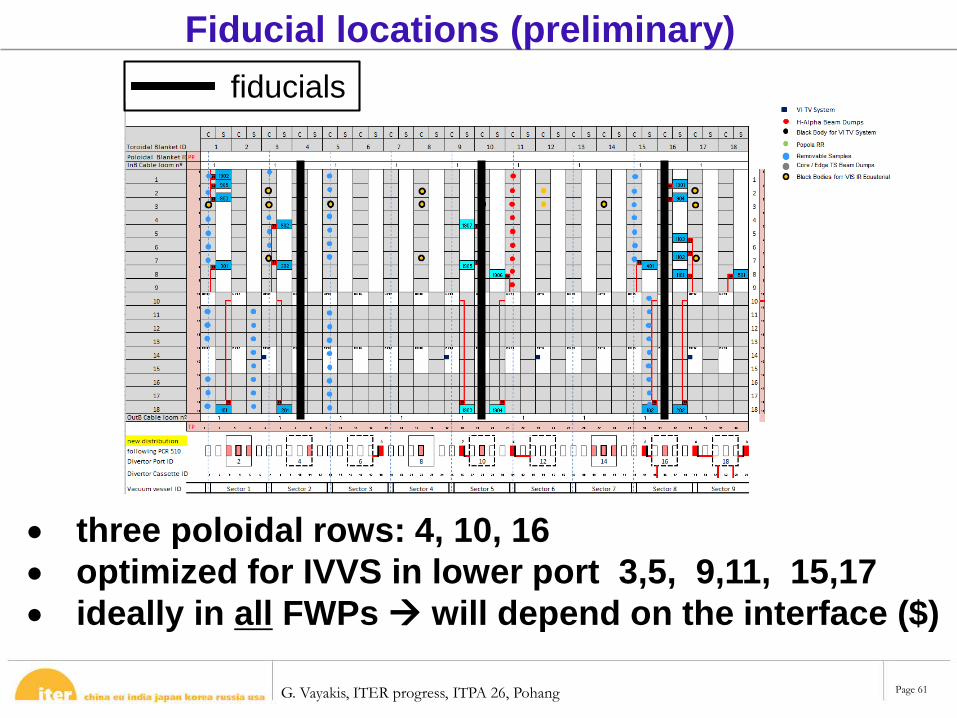
fiducials
Fiducial locations (preliminary)
• three poloidal rows: 4, 10, 16• optimized for IVVS in lower port 3,5, 9,11, 15,17• ideally in all FWPs will depend on the interface ($)
G. Vayakis, ITER progress, ITPA 26, Pohang Page 62
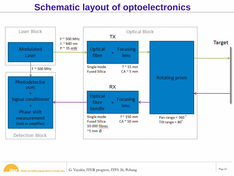
Schematic layout of optoelectronics
G. Vayakis, ITER progress, ITPA 26, Pohang Page 63
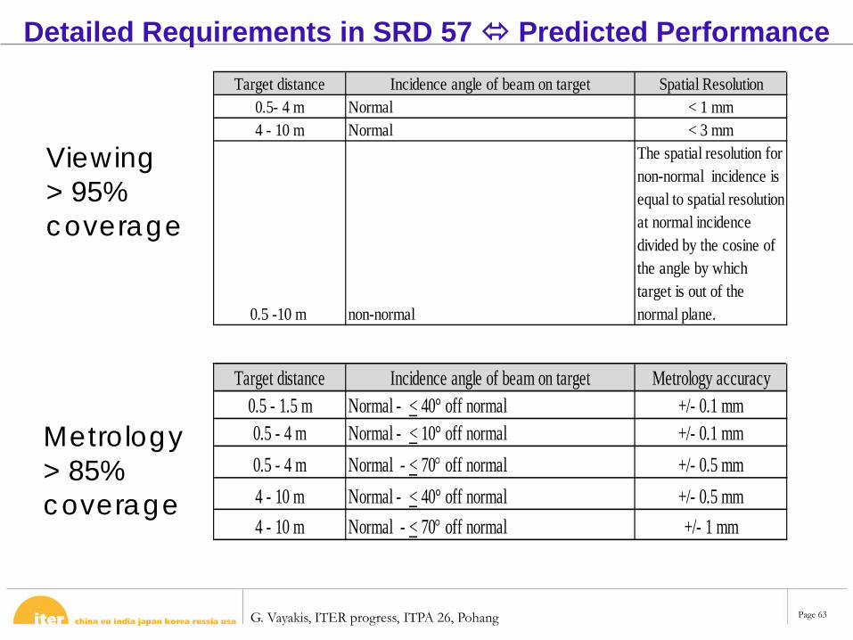
Detailed Requirements in SRD 57 Predicted Performance
Target distance Incidence angle of beam on target Metrology accuracy0.5 - 1.5 m Normal - < 40° off normal +/- 0.1 mm0.5 - 4 m Normal - < 10° off normal +/- 0.1 mm0.5 - 4 m Normal - < 70° off normal +/- 0.5 mm4 - 10 m Normal - < 40° off normal +/- 0.5 mm4 - 10 m Normal - < 70° off normal +/- 1 mm
Target distance Incidence angle of beam on target Spatial Resolution0.5- 4 m Normal < 1 mm4 - 10 m Normal < 3 mm
0.5 -10 m non-normal
The spatial resolution for non-normal incidence is equal to spatial resolution at normal incidence divided by the cosine of the angle by which target is out of the normal plane.
Viewing> 95% coverage
Metrology> 85% coverage
G. Vayakis, ITER progress, ITPA 26, Pohang Page 64
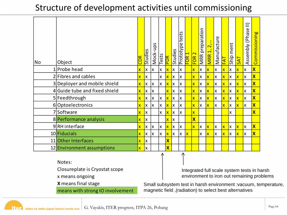
Structure of development activities until commissioning
No Object CDR
Stud
ies
Moc
k-up
sTe
sts
PDR
Stud
ies
Prot
otyp
e te
sts
FDR
1FD
R 2
MRR
pre
para
tion
MRR
1, 2
,…M
anuf
actu
reFA
TSh
ip m
ent
SAT
Asse
mbl
y (P
hase
II)
Com
miss
ioni
ng
1 Probe head x x x x x x x x x x x x x x x X2 Fibres and cables x x x x x x x x x x x x x x X3 Deployer and mobile shield x x x x x x x x x x x x x x x X4 Guide tube and fixed shield x x x x x x x x x x x x x x X5 Feedthrough x x x x x x x x x x x x x x x X6 Optoelectronics x x x x x x x x x x x x x x x X7 Software x x x x x x x x X8 Performance analysis x x x x X9 RH interface x x x x x x x x x x x x x x x X
10 Fiducials x x x x x x x x x x x x x x x X11 Other Interfaces x x X12 Environment assumptions x x X
Notes: Closureplate is Cryostat scopex means ongoingX means final stagemeans with strong IO involvement
Small subsystem test in harsh environment :vacuum, temperature, magnetic field ,(radiation) to select best alternatives
Integrated full scale system tests in harsh environment to iron out remaining problems
G. Vayakis, ITER progress, ITPA 26, Pohang Page 65
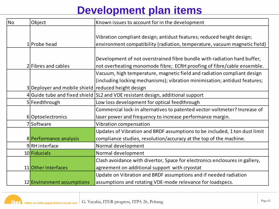
Development plan itemsNo Object Known issues to account for in the development
1 Probe headVibration compliant design; antidust features; reduced height design; environment compatibility (radiation, temperature, vacuum magnetic field)
2 Fibres and cablesDevelopment of not overstrained fibre bundle with radiation hard buffer, not overheating monomode fibre; ECRH proofing of fibre/cable ensemble.
3 Deployer and mobile shield
Vacuum, high temperature, magnetic field and radiation compliant design (including locking mechanisms); vibration minimisation; antidust features; reduced height design
4 Guide tube and fixed shield SL2 and VDE resistant design, additional support5 Feedthrough Low loss development for optical feedthrough
6 OptoelectronicsCommercial lock-in alternatives to patented vector-voltmeter? Increase of laser power and frequency to increase performance margin.
7 Software Vibration compensation
8 Performance analysisUpdates of Vibration and BRDF assumptions to be included, 1 ton dust limit compliance studies, resolution/accuracy at the top of the machine.
9 RH interface Normal development10 Fiducials Normal development
11 Other Interfaces Clash avoidance with divertor, Space for electronics enclosures in gallery, agreement on additional support with cryostat
12 Environment assumptionsUpdate on Vibration and BRDF assumptions and if needed radiation assumptions and rotating VDE-mode relevance for loadspecs.
G. Vayakis, ITER progress, ITPA 26, Pohang Page 66
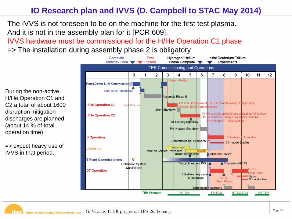
IO Research plan and IVVS (D. Campbell to STAC May 2014) The IVVS is not foreseen to be on the machine for the first test plasma. And it is not in the assembly plan for it [PCR 609].IVVS hardware must be commissioned for the H/He Operation C1 phase=> The installation during assembly phase 2 is obligatory
During the non-active H/He Operation C1 and C2 a total of about 1600 disruption mitigation discharges are planned (about 14 % of total operation time)
=> expect heavy use of IVVS in that period.
G. Vayakis, ITER progress, ITPA 26, Pohang Page 67
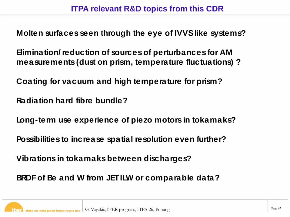
ITPA relevant R&D topics from this CDR
Molten surfaces seen through the eye of IVVS like systems?
Elimination/reduction of sources of perturbances for AM measurements (dust on prism, temperature fluctuations) ?
Coating for vacuum and high temperature for prism?
Radiation hard fibre bundle?
Long-term use experience of piezo motors in tokamaks?
Possibilities to increase spatial resolution even further?
Vibrations in tokamaks between discharges?
BRDF of Be and W from JET ILW or comparable data?
G. Vayakis, ITER progress, ITPA 26, Pohang Page 68
Document and links DDD: https://user.iter.org/?uid=P7MTX3 – leads to all other documents e.g. ICDs, 3D models
SRD: https://user.iter.org/?uid=29NC9X
DCM: ITER_D_3MANB83
Load Specs: Load Specification of PBS 57. In-Vessel Viewing System (PAXCRV v1.0) (current)
Interface meeting report: ITER_D_P8YDT6
Remote handling: https://user.iter.org/?uid=PAUCLP
Functional analysis ITER_D_MU2HZ4⇒Feasibility Risks ITER_D_MU9G2B⇒R&D plan ITER_D_PFNFKG
CDR presentations: https://user.iter.org/?uid=MU7GTX
Chitfolder: https://user.iter.org/?uid=PB5KXT