
IRJET-A Comprehensive Assessment of Racking Deformation for Seismic Response of Rectangular...
6
International Research Journal of Engineering and Technology (IRJET) e-ISSN: 2395 -0056 Volume: 02 Issue: 05 | Aug-2015 www.irjet.net p-ISSN: 2395-0072 © 2015, IRJET ISO 9001:2008 Certified Journal Page 283 A Comprehensive Assessment of Racking Deformation for Seismic Response of Rectangular Underground Structure Chethan P V 1 , Basavana Gowda G M 2 , Govindaraju L 3 , Harsha G M 4 1 Research scholar, Civil Engineering, M.S.Ramaiah Institute of Technology, Karnataka, India 2 Assistant Professor, Civil Engineering, M.S.Ramaiah Institute of Technology, Karnataka, India 3 Associate Professor, Civil Engineering, UVCE, Bangalore University, Bangalore, Karnataka, India 4 Research scholar, Civil Engineering, M.S.Ramaiah Institute of Technology, Karnataka, India ---------------------------------------------------------------------***--------------------------------------------------------------------- Abstract - Substructure facilities are the important part of the modern society constructions. For Example: Transportation facilities (subways, highways and railways), material storage, water supply and drainage etc. These substructure facilities built in earthquake prone areas must withstand both static and seismic (dynamic) loading. An effort has been made in the present study to find racking deformation of underground metro station located in Bangalore, India. Using plaxis8.2 (Finite Element method) software, racking deformation was computed and compared with the deformation obtained using analytical method. Seismic design loads for underground structures are defined in terms of the deformations and strains developed on the structure due to surrounding soil or due to the interaction between soil and the structure. The free-field analysis was carried out to find the ground deformation due to seismic (Dynamic) load, and the substructures has to designed to accommodate these deformations. Key Words: Soil-Structure Interaction, Free-field deformation, Flexibility ratio, Racking deformation. 1. INTRODUCTION 1.1 General Earthquakes are the most destructive of all natural hazards. In fact, Bangalore has experienced several minor earthquakes in the 20th century. Due to earthquake, structures may get damaged at different levels namely superstructure or sub-structural level or at the interface of two. But, the degree of damage occurred during the earthquake is strongly influenced by the response of the supporting soil. The interaction between soil and structure during an earthquake are expected to be different than the analysis of a single structure without the interaction of subsoil. The properties of soil system are often difficult to assess, Soil being a natural geological material. Thus it has been customary to assign large factors of safety to soil stresses when compared to those of superstructure. In such a situation, the soil stresses generally do not cross the elastic range except probably in the small overstressed zones. Hence, in the present analysis the soil system is assumed to be in elastic state. The process in which the response of the soil influences the motion of the structure and the motion of the structure influences the response of the soil is termed as “SOIL-STRUCTRE INTERACTION” (SSI). Soil-Structure interaction makes a structure more flexible increasing the natural period of the structure. Previous studies have shown that the bending moments and shear force values in the structure are more when the soil-structure interaction effect is considered. The seismic response of an underground structure is different from the response of a superstructure founded on the ground surface. The confining action of surrounding soil media is the main reason for this difference. In simple words, while superstructures are free vibrating systems, underground structures deform compatibly with the surrounding soil stratum. This fact encourages many of researchers and engineers to pursue deformation-based studies in the seismic design of underground structures, since none of the available force-based methods have been developed to take into account the deformation compatibility. In many of the cases, seismic effects for box culverts and buried structures will not be considered except when they are subjected to unstable ground conditions (e.g., liquefaction, landslides, and fault displacements) or large ground deformations (e.g., in very soft ground). The above statement uses significantly subjective and undefined terms such as “large ground deformations” or “very soft ground”. Most of the case studies have shown that soil profiles composed of medium dense or medium stiff layers may also experience large deformations, if they are subjected to strong ground motions having higher intensity. Also it is the engineer’s responsibility to check that the designed structure can satisfactorily resist the
description
Substructure facilities are the important part of the modern society constructions. For Example: Transportation facilities (subways, highways and railways), material storage, water supply and drainage etc. These substructure facilities built in earthquake prone areas must withstand both static and seismic (dynamic) loading. An effort has been made in the present study to find racking deformation of underground metro station located in Bangalore, India. Using plaxis8.2 (Finite Element method) software, racking deformation was computed and compared with the deformation obtained using analytical method. Seismic design loads for underground structures are defined in terms of the deformations and strains developed on the structure due to surrounding soil or due to the interaction between soil and the structure. The free-field analysis was carried out to find the ground deformation due to seismic (Dynamic) load, and the substructures has to designed to accommodate these deformations.
Transcript of IRJET-A Comprehensive Assessment of Racking Deformation for Seismic Response of Rectangular...

International Research Journal of Engineering and Technology (IRJET) e-ISSN: 2395 -0056
Volume: 02 Issue: 05 | Aug-2015 www.irjet.net p-ISSN: 2395-0072
© 2015, IRJET ISO 9001:2008 Certified Journal Page 283
A Comprehensive Assessment of Racking Deformation for Seismic
Response of Rectangular Underground Structure
Chethan P V1, Basavana Gowda G M2, Govindaraju L3, Harsha G M4
1 Research scholar, Civil Engineering, M.S.Ramaiah Institute of Technology, Karnataka, India 2 Assistant Professor, Civil Engineering, M.S.Ramaiah Institute of Technology, Karnataka, India
3 Associate Professor, Civil Engineering, UVCE, Bangalore University, Bangalore, Karnataka, India 4 Research scholar, Civil Engineering, M.S.Ramaiah Institute of Technology, Karnataka, India
---------------------------------------------------------------------***---------------------------------------------------------------------Abstract - Substructure facilities are the important
part of the modern society constructions. For Example:
Transportation facilities (subways, highways and
railways), material storage, water supply and drainage
etc. These substructure facilities built in earthquake
prone areas must withstand both static and seismic
(dynamic) loading. An effort has been made in the
present study to find racking deformation of
underground metro station located in Bangalore, India.
Using plaxis8.2 (Finite Element method) software,
racking deformation was computed and compared with
the deformation obtained using analytical method.
Seismic design loads for underground structures are
defined in terms of the deformations and strains
developed on the structure due to surrounding soil or
due to the interaction between soil and the structure.
The free-field analysis was carried out to find the
ground deformation due to seismic (Dynamic) load, and
the substructures has to designed to accommodate
these deformations.
Key Words: Soil-Structure Interaction, Free-field
deformation, Flexibility ratio, Racking deformation.
1. INTRODUCTION 1.1 General
Earthquakes are the most destructive of all natural hazards. In fact, Bangalore has experienced several minor earthquakes in the 20th century. Due to earthquake, structures may get damaged at different levels namely superstructure or sub-structural level or at the interface of two. But, the degree of damage occurred during the earthquake is strongly influenced by the response of the supporting soil. The interaction between soil and structure during an earthquake are expected to be different than the analysis of a single structure without the interaction of subsoil.
The properties of soil system are often difficult to
assess, Soil being a natural geological material. Thus it has been customary to assign large factors of safety to soil stresses when compared to those of superstructure. In such a situation, the soil stresses generally do not cross the elastic range except probably in the small overstressed zones. Hence, in the present analysis the soil system is assumed to be in elastic state.
The process in which the response of the soil influences the motion of the structure and the motion of the structure influences the response of the soil is termed as “SOIL-STRUCTRE INTERACTION” (SSI). Soil-Structure interaction makes a structure more flexible increasing the natural period of the structure. Previous studies have shown that the bending moments and shear force values in the structure are more when the soil-structure interaction effect is considered.
The seismic response of an underground structure is different from the response of a superstructure founded on the ground surface. The confining action of surrounding soil media is the main reason for this difference. In simple words, while superstructures are free vibrating systems, underground structures deform compatibly with the surrounding soil stratum. This fact encourages many of researchers and engineers to pursue deformation-based studies in the seismic design of underground structures, since none of the available force-based methods have been developed to take into account the deformation compatibility.
In many of the cases, seismic effects for box culverts and buried structures will not be considered except when they are subjected to unstable ground conditions (e.g., liquefaction, landslides, and fault displacements) or large ground deformations (e.g., in very soft ground).
The above statement uses significantly subjective and undefined terms such as “large ground deformations” or “very soft ground”. Most of the case studies have shown that soil profiles composed of medium dense or medium stiff layers may also experience large deformations, if they are subjected to strong ground motions having higher intensity. Also it is the engineer’s responsibility to check that the designed structure can satisfactorily resist the

International Research Journal of Engineering and Technology (IRJET) e-ISSN: 2395 -0056
Volume: 02 Issue: 05 | Aug-2015 www.irjet.net p-ISSN: 2395-0072
© 2015, IRJET ISO 9001:2008 Certified Journal Page 284
probable seismic excitations, as well as the service loads during its lifetime. Hence, it is strongly recommended to check seismic performances of underground structures in seismically active regions.
Many researchers have carried out the seismic performance evaluation of underground structures after a wide range of seismic events. Sharma and Judd(1991)[12] performed a comprehensive study on damage patterns in buried structures and their findings reveals that underground structures are also vulnerable to seismically-induced failures and damages. Although they are considered to be seismically safe when designed for service loads, seismic performance of the underground structures should be checked especially for scenarios including high magnitude events and small overburden levels. Shallow tunnel, i.e. when overburden is less than 15 m, are usually designed as cut and cover structures and these structures are more vulnerable to seismically-induced damages compared to deeper tunnels (Y.M.A.Hashash et al., [1]). As stated by Wang[10], as the depth of burial decreases: (i) lower confinement action results from lower overburden pressure, and (ii) higher amount of displacement is observed. Moreover, these shallow buried structures are subjected to higher levels of forces owing to their higher rigidities (Y.M.A.Hashash et al., [1]).
1.2 Local site effects and site specific response analysis
Dynamic analysis is generally believed to provide the most realistic predictions of structural response induced by earthquake ground motions. The forces on structures depend on peak ground acceleration and time period of structure. Subsoil condition is responsible for the amplification of ground motion and amplification may increase or decrease the value of spectral acceleration coefficient.
The seismic waves travel from the bedrock to the surface with certain change in its characteristics (i.e. amplitude and frequency of seismic waves) because; they pass through the different soil deposits. This process may transfer large accelerations to the structure and thus causing large deformation. Site specific ground response analysis aims to determine this effect of local soil conditions on amplification of seismic waves and hence estimating the ground response spectra for the design purposes. 1.3 Calculation of Racking Deformation
In reviewing technology advances through the centuries, it is evident that underground structures play a key role in construction industry. Hence, design of underground structures for seismic activity is very important. Finding racking deformation of underground structures using analytical method requires soil and structural parameters such as soil density, type of soil, velocity of S-wave propagations in soil medium, Peak
ground particle acceleration at surface, dimensions of the box structure (metro station box), magnitude of earthquake and epicenter distance (source to site distance). Using some of these parameters firstly the free- field deformation can be evaluated. Secondly, the flexibility ratio values can be obtained through formulas from literatures. Finally, the racking co-efficient can be arrived using the relationship between flexibility ratio and racking co-efficient for rectangular tunnel. Multiplying this racking co-efficient with the obtained free-field deformation gives the racking deformation of the structure. 1.4 Racking deformation and Structural Response due to Seismic event using PLAXIS8.2 software
The location of the metro station box considered is situated near Chinnaswammy Cricket Stadium in Bangalore (India). The structure is 3.5 m below ground level, width and height of the structure are 21m and 14m respectively. A model has been created based-on structural details obtained from CEC-SOMA-CICI JV. Soil report collected from CEC-SOMA-CICI JV contains the details of density of soil, type of soils and different layers of soil. Soil depth considered for analysis was up-to 30 m deep from ground surface. Different soil layers were encountered during the investigation. These different soil layers were modeled in PLAXIS 8.2 software. Each layer details were assigned with their respective properties. Earthquake ground motion data was collected from Pacific Earthquake Engineering Research (PEER) database to simulate the ground shaking, as it is one of the important parameters for dynamic analysis. This ground motion was given as an input in PLAXIS 8.2 software for dynamic analysis. Racking deformation obtained using software was compared with the racking deformation obtained from analytical expression.
2. SOIL AND STRUCTURE PARAMETERS 2.1 Site Description and its Seismity
The proposed Bangalore Metro UG 2 starts from Ch.6.350 km, near city railway Station and ends at Ch.11.200 km, near Chinnaswamy Cricket Stadium. The terrain is gently undulating and the existing ground level (EGL) varies from +896.638 m to +923.328 m. The UG corridor transverses through cricket stadium – General Post Office – Vidhan Soudha – KG road – City bus stand (Majestic) – City Railway Station. Bangalore falls under Zone II of Seismic Zoning Map as per IS: 1893 (part I) – 2002. Recent earthquakes that occurred close to Bangalore were in the range of 2.0 to 5.5 on Richter scale. On January 29, 2001, an earthquake with a magnitude of 4.3 on the Richter scale hit in the Mandya area, with its epicenter about 35 km south of Bangalore.

International Research Journal of Engineering and Technology (IRJET) e-ISSN: 2395 -0056
Volume: 02 Issue: 05 | Aug-2015 www.irjet.net p-ISSN: 2395-0072
© 2015, IRJET ISO 9001:2008 Certified Journal Page 285
2.1.1 Sub-soil profile Layer I: Sandy silt
This layer has been noticed as the top layer in the boreholes. The thickness of this layer was found to be 6m and recorded N-values in this layer was 7. Layer II: Silty Sand/ Highly weathered rock
This layer had a thickness of 7.5m. Silty sand was noticed below the sandy silt layer and highly weathered rock layer was noticed below the sandy silt layer. The N-values in silty sand layer vary from 12 to 23, indicating 'Medium' in-situ compactness of the soil. The N-values in highly weathered rock layer are greater than 100, indicating 'Věry Dense' in-situ compactness of soil. Layer III: Hard Rock
Hard rock was noticed below the silty sand layer. The thickness of this layer was 7.5m.
The range of Poison’s ratio, P-waves and S-waves
velocity values in various soil layers found during the soil investigation is mentioned in Table 1. Table 1: Variation in Poisson’s ratio, P and S-waves velocity in different soil layers [CEC-SOMA-CICI JV (14)]
2.2 Structural parameters Considered structure was a rectangular underground metro station box which is 3.5m below ground level having width and height of 21m and 14m respectively. The thickness of base and roof slab was found to be 1.4m. The thickness of side walls was 1m. The grade of concrete used for the construction was 35MPa.
3. MODELING AND ANALYSIS USING PLAXIS 8.2 The method adopted in software (Plaxis8.2) for modeling and analysis was Finite Element Analysis (FEM). Soil layers in finite element assessments are modeled as linear elastic. For the accuracy of the results 15-Node elements was adopted. The soil consists of three different layers with different parameters. Analyzing the above parameters in cross-section the width of the model was
taken as 51m and the depth as 30m (up-to rock bed) as show in Fig 1.
Fig-1: Dimensions and soil layers of the generated soil-structure model. (All dimensions are in mm)
Using the values of soil density [saturated (ᵞsat)
and un-saturated (ᵞunsat)], Poisson’s ratio of soil (µs), Young’s modulus of soil (Es), cohesion of soil (C), Velocities of S-waves (Vs) and P-waves (Vp) respective layers were generated and assigned. Similarly, using young’s modulus of concrete (Ec), area of cross section per meter width (A), moment of inertia of the structure (I), Self weight of individual slab per meter (W), Poison’s ratio of concrete (µc) different member properties were formed and assigned for structure. Using the upland earthquake data which is having magnitude of 5.4, and Peak Ground Acceleration (PGA) 0.24g, dynamic analysis was carried out. The Racking deformation of the structure was found to be 4.02mm.
4. ANALYTICAL METHOD TO FIND RACKING DEFORMATION Here the method developed by Hashash et al., 2001 (1) was used to find the racking deformation. Basic data required in this analytical method are stated as below.
Earthquake and soil parameters
Peak Magnitude of previous earthquakes at study site (Mw) = 5.4
Peak ground particle acceleration at surface, (amax) = 0.24g
Apparent velocity of s-wave propagation in soil (Cm) = 229.33 m/sec. [CEC-SOMA-CICI JV (14)]
Structural parameters.
International Research Journal of Engineering and Technology (IRJET) e-ISSN: 2395 -0056
Volume: 02 Issue: 05 | Aug-2015 www.irjet.net p-ISSN: 2395-0072
© 2015, IRJET ISO 9001:2008 Certified Journal Page 286
Width of the station box (L) = 21 m. Height of the station box (H) = 14 m. Depth of soil layer to the top of station box (D) =
3.5 m. Per unit Length for the rectangular cross section
was considered.
4.1 Determination of the free-field deformation (∆ free-field).
As per the collected earthquake data peak ground acceleration (amax) at the ground surface is found to be 0.24g. Since, the present scope of work is concentrated on the underground structure the peak ground acceleration at the depth of tunnel (as) was computed as 0.192g (0.8 * amax); 0.8 is the ratios of ground motion at depth to motion at ground surface obtained from Table 2. Table 2: Ratios of ground motion at depth to motion at ground surface [Y M A Hashash et al., 2001 (1)]
Assuming stiff soil medium, peak ground velocity at the depth of tunnel obtained was 0.2093 m/s (102 * as); 102 is the Ratio between peak ground velocity to peak ground acceleration at the surface in rock and soil as shown in Table 3. Table 3: Ratio between peak ground velocity to peak ground acceleration at the surface in rock and soil [Y M A Hashash et al., 2001 (1)].
Calculated peak ground velocity at the tunnel depth was divided by the velocity of S-wave propagated in the soil medium to obtain shear strain, which was 9.1266*10-4. By multiplying the obtained shear strain with the height of the structure (H), Free-field deformation of 11.955mm was arrived.
4.2 Determination of Flexibility ratio (FR) [J H Wood, 2007(7)] In assessing soil-structure interaction effects on underground structures it is usual to define flexibility ratio. Flexibility ratio is defined as the ratio between shear flexibility of free standing structure without soil interaction (fst) to shear flexibility of soil block of same overall dimensions as structure (fs).
=
Using the above relation the flexibility ratio computed was FR = 0.3055.
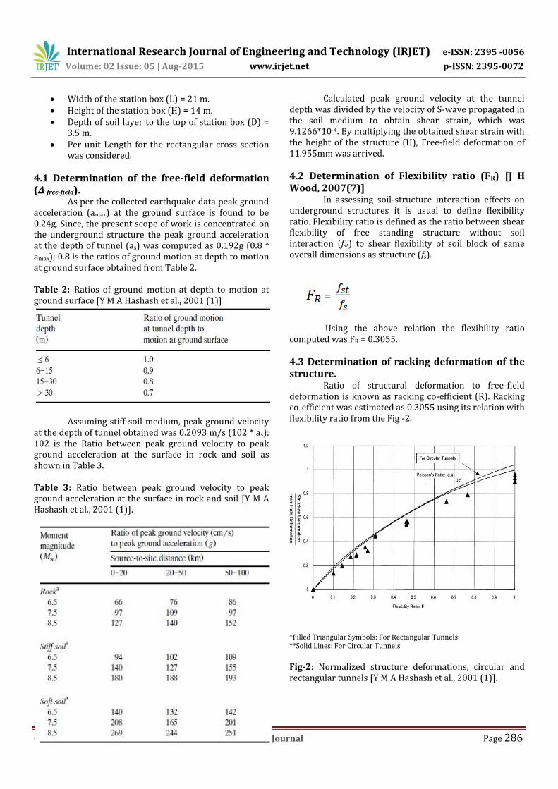
4.3 Determination of racking deformation of the structure. Ratio of structural deformation to free-field deformation is known as racking co-efficient (R). Racking co-efficient was estimated as 0.3055 using its relation with flexibility ratio from the Fig -2.
*Filled Triangular Symbols: For Rectangular Tunnels **Solid Lines: For Circular Tunnels
Fig-2: Normalized structure deformations, circular and rectangular tunnels [Y M A Hashash et al., 2001 (1)].

International Research Journal of Engineering and Technology (IRJET) e-ISSN: 2395 -0056
Volume: 02 Issue: 05 | Aug-2015 www.irjet.net p-ISSN: 2395-0072
© 2015, IRJET ISO 9001:2008 Certified Journal Page 287
Multiplying racking coefficient (R) with free-field deformation, racking deformation of the structure has found to be 3.652mm.
5. CONCLUSIONS Seismic analysis of substructure was carried out using PLAXIS 8.2 software and Analytical method to compute Racking deformation. The following conclusions were drawn based on the results:
Soil properties play an important role in all sub-structures during soil-structure Interaction.
Peak Ground Acceleration (PGA) depends on soil properties (Soil density, Young’s modulus of soil, Shear modulus, poison’s ratio, etc.,)
Racking deformation obtained using PLAXIS 8.2 software was 4.02mm.
Computed Free-field deformation and Racking deformation using Analytical method were 11.955mm and 3.652mm respectively.
Deformation of structure during soil structure interaction was dependent on Flexibility ratio of the structure.
REFERENCES [1] Youssef M.A. Hashash, Jeffrey J. Hook, Birger Schmidt,
John I-Chiang Yao. “Seismic design and analysis of underground structures”. Tunnelling and underground space technology16, USA, 2001, pages 247-293.
[2] Hamid Reza Nejati, Morteza Ahmadi and Hamid Hashemolhosseini. “An investigation on the ground motion parameters and seismic response of underground strucutres”. Earthquake science (2012) 25, 253-261.
[3] Youssef M.A. Hashash, Karina Karina, Demetrious Koutsoftas and Nick O’Riordan. “seismic design considerations for underground box structures”. 2012.
[4] Omer Aydan, Yoshimi Ohta, Melih Genis, Naohiko Tokashiki, K. Ohkubo. “Response and Stability of Underground Structures in Rock Mass during Earthquakes”. Rock Mech Rock Eng (2010) 43: 857-875.
[5] Ali guney ozcebe. “A Comparative Assessment of available Methods for Seismic performance evaluation of Buried Structures”. Middle East Technical University 2009.
[6] E.Debiasi, A.Gajo, D.Zonta. “On the Seismic Response of Shallow-Buried Rectangular Structures”. Tunnelling and underground space technology 38 (2013) 99-113.
[7] J.H.Wood. “Earthquake Design of Rectangular Underground Structures”. Bulletin of the New
Zealand Society for Earthquake Engineering, Vol.40, No.1, March 2007.
[8] J.H.Wood. “Earthquake Design Procedures for Rectangular Underground Strucutres”. Earthquake commission research foundation 2004.
[9] P.Anbazhagan ang T.G.Sitharam. “Seismic Microzonation of Bangalore, India”. J.Earth syst. Sci. 117, S2, November 2008, pp.833-852.
[10] Wang, J.N. “Seismic Design of Tunnels”, Monograph 7, Parsons Brinckerhoff Quade and Douglas, Inc, 1993.
[11] Wang W L, Wang T T, Su J J, Lin C H, Seng C R and Huang T H (2001). “Assessment of damage in mountain tunnels due to the Taiwan Chi-Chi earthquake”. Tunnelling and underground space technology 16(13): 133-150.
[12] Sharma,s., Judd, W.R., 1991. “Underground opening damage from Earthquake”. Engineering geol. 30, 263-276.
[13] BHRC (Building and Housing Research Centre) (2008). Changureh-Avaj Earthquake, June 22th 2002.
[14] CEC-SOMA-CICI JV. “Geotechnical investigation at Station and Tunnel Locations – Bangalore Metro UG 2”. SECON Private Limited. Soil report 2010.
[15] Arango, Ignacio (2008) “Earthquake engineering for tunnels and underground strucutres. A case history.,” In: David Zeng, Majid T.Manzari, and Dennis R.Hiltunen,Eds., Geotechnical Earthquake Engineering and Soil Dynamics IV.
[16] Power, M.S., Rosidi, D., Kaneshiro, J., 1996. Vol. III Strawman: screening, evaluation, and retrofit design of tunnels. Report Draft. National Center for Earthquake Engineering Research, Buffalo, New York.
[17] ASTM D 7400-08: “Standard Test Methodsfor Down Hole Seismic Testing”.
[18] IS 1498-1970:“Classification and Identification of Soils for General Engineering Purpose”, Bureau of Indián Standards, New Delhi.
[19] IS 2131-1981:“Method of Standard Penetration Test”, Bureau of Indián Standards, New Delhi.
[20] IS: 1893 (part I) – 2002.
BIOGRAPHIES
Name: CHETHAN P V Qualification: M-Tech (Structural Engg.) Research area: Earthquake Engineering. Contact number: 8553632733 Email id: [email protected]

International Research Journal of Engineering and Technology (IRJET) e-ISSN: 2395 -0056
Volume: 02 Issue: 05 | Aug-2015 www.irjet.net p-ISSN: 2395-0072
© 2015, IRJET ISO 9001:2008 Certified Journal Page 288
Name: BASAVANA GOWDA G M Designation: Assistant Professor, M S Ramaiah Institute of Technology, Bangalore, Karnataka, India. Qualification: ME, Ph.D*(Civil Engg.) Research area: Earthquake Engineering. Contact number: 9945877955 Email id: [email protected]
Name: Dr. GOVINDARAJU L Designation: Associate Professor, UVCE, Bangalore university, Bangalore, Karnataka, India. Qualification: M.tech (Geotechnical Engineering), Ph.D(Civil Engg.) Research area: Geotechnical Earthquake Engineering. Contact number: 9731336546 Email id: [email protected]
Name: HARSHA G M Qualification: M-Tech (Structural Engg.) Research area: Earthquake Engineering. Contact number: 9964137726 Email id: [email protected]