IRJET-Strength and deformation of rectangular two way simply supported SFR-HSSCC slabs
8
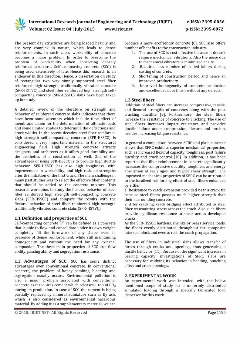
International Research Journal of Engineering and Technology (IRJET) e-ISSN: 2395-0056 Volume: 02 Issue: 04 | July-2015 www.irjet.net p-ISSN: 2395-0072 © 2015, IRJET.NET- All Rights Reserved Page 1189 Strength and deformation of rectangular two way simply supported SFR-HSSCC slabs Ramesh Patil 1 , V.Harish 2 1 Research scholar, Department of Civil Engineering, MSRIT, Bangalore, Karnataka, India 2 Assistant professor, Department of Civil Engineering, MSRIT, Bangalore, Karnataka, India ---------------------------------------------------------------------***--------------------------------------------------------------------- Abstract - A reinforced concrete slab forms an important structural element in civil engineering practice. To analyze and design these slabs earlier attempts were made on the basis of elastic analysis. With the development of ultimate load methods, yield line analysis appeared as an accepted method for the prediction of ultimate loads of slabs. However, most of the test results of earlier researches showed that, the slab could carry much more load than that predicted from yield line analysis, due the inducement of membrane forces at finite deflections. A number of investigations have been carried out in last forty years to study the effect of membrane action on ultimate loads of reinforced concrete slabs. These methods predict the ultimate loads with an assumed value of deflection of the slab at ultimate loads. The gradual development of limit state method has brought into consideration the importance of serviceability criteria regarding deflections and crack widths along with strength of the structure. This paper investigates the strength and deformation of rectangular two way simply supported steel fiber reinforced high strength self-compacting concrete slabs under simulated uniform loading. The experimental programme consisted of casting and testing of four slabs of SFR- HSTVC and four slabs of SFR-HSSCC with a grade of M70, with different percentages of crimped steel fibers as 0.25%, 0.50%, 0.75% and 1.0%. All the eight slabs were 75mm thick. These slabs were subjected to uniformly distributed loads. The uniformly distributed loading was simulated by using a sixteen point load disperser specially fabricated for the tests. During testing of the slabs quantum of load was applied and the corresponding central deflections and crack widths were recorded. The load deformation behavior, ultimate strengths and cracking behavior were studied and presented in this work. The study showed that, load enhancement is directly proportional to the percentage of steel fibers. Key Words: Two way RC slabs, HSTVC, HSSCC, steel fibers, ultimate load, deflection and cracking. 1. INTRODUCTION Reinforced concrete slabs are one of the important structural components in civil engineering construction, which constitutes 40% of the concrete used in a building project. The slab is required to carry the applied load directly and then transfer it to the supports. The supports may be in the form of load bearing walls or beams or columns. The behavior of slab is fundamentally based on its support conditions. Two way slabs span in both directions having an aspect ratio of ‘longer span/shorter span’ less than or equal to 2. Two way slabs are generally subjected to uniformly distributed loads, resisting them primarily by bending about both the axes [1]. The section of slabs are checked for shear and generally no shear reinforcement is required. The slab should have sufficient depth to limit the deflection within codal provisions [2]. Thus, strength and deflection are the requirements for design of slabs. The present day structural systems are highly complex in nature and are highly stressed due to heavy loadings. This results in larger sections for structural members to resist forces with normal strength concrete. Therefore, High strength concrete structural elements are being extensively used in the design to make sections of the structural member aesthetic with high load resisting capacity. In simply supported slabs, membrane forces develop at large deflections [3[4][5]. With large deflections at mid span, the central region of the supported edges tend to move inwards but are restrained from doing by adjacent outer regions. This creates the central area of the tensile membrane stresses within the slab together with a surrounding ring of compression. This effect enhances the load carrying capacity of the slab [6]. Self-compacting concrete (SCC) is one of the recent developments in concrete with special purpose. Initially it was published as a high performance concrete, which has all the desired properties of SCC mix. Later on many researchers started working on this new type of concrete which super workable, self-consolidating, self-place able and highly fluidized concrete. Then onwards it has been called as SCC. The development of SCC was due to the problem of durability and scarcity of skilled labors.
description
A reinforced concrete slab forms an important structural element in civil engineering practice. To analyze and design these slabs earlier attempts were made on the basis of elastic analysis. With the development of ultimate load methods, yield line analysis appeared as an accepted method for the prediction of ultimate loads of slabs. However, most of the test results of earlier researches showed that, the slab could carry much more load than that predicted from yield line analysis, due the inducement of membrane forces at finite deflections. A number of investigations have been carried out in last forty years to study the effect of membrane action on ultimate loads of reinforced concrete slabs. These methods predict the ultimate loads with an assumed value of deflection of the slab at ultimate loads. The gradual development of limit state method has brought into consideration the importance of serviceability criteria regarding deflections and crack widths along with strength of the structure. This paper investigates the strength and deformation of rectangular two way simply supported steel fiber reinforced high strength self-compacting concrete slabs under simulated uniform loading. The experimental programme consisted of casting and testing of four slabs of SFR-HSTVC and four slabs of SFR-HSSCC with a grade of M70, with different percentages of crimped steel fibers as 0.25%, 0.50%, 0.75% and 1.0%. All the eight slabs were 75mm thick. These slabs were subjected to uniformly distributed loads. The uniformly distributed loading was simulated by using a sixteen point load disperser specially fabricated for the tests. During testing of the slabs quantum of load was applied and the corresponding central deflections and crack widths were recorded. The load deformation behavior, ultimate strengths and cracking behavior were studied and presented in this work. The study showed that, load enhancement is directly proportional to the percentage of steel fibers.
Transcript of IRJET-Strength and deformation of rectangular two way simply supported SFR-HSSCC slabs
International Research Journal of Engineering and Technology (IRJET) e-ISSN: 2395-0056
Volume: 02 Issue: 04 | July-2015 www.irjet.net p-ISSN: 2395-0072
© 2015, IRJET.NET- All Rights Reserved Page 1189
Strength and deformation of rectangular two way simply supported SFR-HSSCC slabs
Ramesh Patil1, V.Harish2
1 Research scholar, Department of Civil Engineering, MSRIT, Bangalore, Karnataka, India 2 Assistant professor, Department of Civil Engineering, MSRIT, Bangalore, Karnataka, India
---------------------------------------------------------------------***---------------------------------------------------------------------Abstract - A reinforced concrete slab forms an important structural element in civil engineering practice. To analyze and design these slabs earlier attempts were made on the basis of elastic analysis. With the development of ultimate load methods, yield line analysis appeared as an accepted method for the prediction of ultimate loads of slabs. However, most of the test results of earlier researches showed that, the slab could carry much more load than that predicted from yield line analysis, due the inducement of membrane forces at finite deflections. A number of investigations have been carried out in last forty years to study the effect of membrane action on ultimate loads of reinforced concrete slabs. These methods predict the ultimate loads with an assumed value of deflection of the slab at ultimate loads. The gradual development of limit state method has brought into consideration the importance of serviceability criteria regarding deflections and crack widths along with strength of the structure. This paper investigates the strength and deformation of rectangular two way simply supported steel fiber reinforced high strength self-compacting concrete slabs under simulated uniform loading. The experimental programme consisted of casting and testing of four slabs of SFR-HSTVC and four slabs of SFR-HSSCC with a grade of M70, with different percentages of crimped steel fibers as 0.25%, 0.50%, 0.75% and 1.0%. All the eight slabs were 75mm thick. These slabs were subjected to uniformly distributed loads. The uniformly distributed loading was simulated by using a sixteen point load disperser specially fabricated for the tests. During testing of the slabs quantum of load was applied and the corresponding central deflections and crack widths were recorded. The load deformation behavior, ultimate strengths and cracking behavior were studied and presented in this work. The study showed that, load enhancement is directly proportional to the percentage of steel fibers.
Key Words: Two way RC slabs, HSTVC, HSSCC, steel fibers, ultimate load, deflection and cracking. 1. INTRODUCTION
Reinforced concrete slabs are one of the important structural components in civil engineering construction, which constitutes 40% of the concrete used in a building project. The slab is required to carry the applied load directly and then transfer it to the supports. The supports may be in the form of load bearing walls or beams or columns. The behavior of slab is fundamentally based on its support conditions.
Two way slabs span in both directions having an aspect ratio of ‘longer span/shorter span’ less than or equal to 2. Two way slabs are generally subjected to uniformly distributed loads, resisting them primarily by bending about both the axes [1]. The section of slabs are checked for shear and generally no shear reinforcement is required. The slab should have sufficient depth to limit the deflection within codal provisions [2]. Thus, strength and deflection are the requirements for design of slabs. The present day structural systems are highly complex in nature and are highly stressed due to heavy loadings. This results in larger sections for structural members to resist forces with normal strength concrete. Therefore, High strength concrete structural elements are being extensively used in the design to make sections of the structural member aesthetic with high load resisting capacity. In simply supported slabs, membrane forces develop at large deflections [3[4][5]. With large deflections at mid span, the central region of the supported edges tend to move inwards but are restrained from doing by adjacent outer regions. This creates the central area of the tensile membrane stresses within the slab together with a surrounding ring of compression. This effect enhances the load carrying capacity of the slab [6]. Self-compacting concrete (SCC) is one of the recent developments in concrete with special purpose. Initially it was published as a high performance concrete, which has all the desired properties of SCC mix. Later on many researchers started working on this new type of concrete which super workable, self-consolidating, self-place able and highly fluidized concrete. Then onwards it has been called as SCC. The development of SCC was due to the problem of durability and scarcity of skilled labors.
International Research Journal of Engineering and Technology (IRJET) e-ISSN: 2395-0056
Volume: 02 Issue: 04 | July-2015 www.irjet.net p-ISSN: 2395-0072
© 2015, IRJET.NET- All Rights Reserved Page 1190
The present day structures are being loaded heavily and are very complex in nature, which leads to dense reinforcements. In such cases workability of concrete becomes a major problem. In order to overcome the problem of workability when concreting densely reinforced structures Self compacting concrete (SCC) is being used extensively of late. Hence this research is an endeavor in this direction. Hence, a dissertation on study of rectangular two way simply supported steel fiber reinforced high strength traditionally vibrated concrete (SFR-HSTVC) and steel fiber reinforced high strength self-compacting concrete (SFR-HSSCC) slabs have been taken up for study. A detailed review of the literature on strength and behavior of reinforced concrete slabs indicates that there have been some attempts which include time effect of membrane action for the determination of ultimate loads and some limited studies to determine the deflections and crack widths. In the recent decades, steel fiber reinforced high strength self-compacting concrete (SFR-HSSCC) is considered a very important material in the structural engineering field. High strength concrete attracts designers and architects as it offers good durability and the aesthetics of a construction as well. One of the advantages of using SFR-HSSCC is to provide high ductile behavior. SFR-HSSCC has also high toughness, with improvement in workability, and high residual strengths after the initiation of the first crack. The main challenge in many past studies was to select the effective fiber contents that should be added to the concrete mixture. This research work aims to study the flexural behavior of steel fiber reinforced high strength self-compacting concrete slabs (SFR-HSSCC) and compare the results with the flexural behavior of steel fiber reinforced high strength traditionally vibrated concrete slabs (SFR-HSTVC).
1.1 Definition and properties of SCC Self-compacting concrete [7] can be defined as a concrete that is able to flow and consolidate under its own weight, completely fill the formwork of any shape, even in presence of dense reinforcement, while still maintaining homogeneity and without the need for any external compaction. The three main properties of SCC are: flow ability, passing ability and segregation resistance.
1.2 Advantages of SCC: SCC has some distinct advantages over conventional concrete. In conventional concrete, the problem of honey combing, bleeding and segregation usually occurs. Environmental pollution is also a major problem associated with conventional concrete as it requires cement which releases 1 ton of CO2
during its production. In case of SCC the cement is being partially replaced by mineral admixture such as fly ash, which is also considered as environmental hazardous material. By adding it as a supplementary material, we can
produce a more ecofriendly concrete [8]. SCC also offers number of benefits to the construction industry.
1. The use of SCC is cost effective because it doesn’t require mechanical vibrations. Also the noise due to mechanical vibrators is minimized at site.
2. Requires less number of skilled labors during casting of concrete.
3. Shortening of construction period and hence an improved productivity.
4. Improved homogeneity of concrete production and excellent surface finish without any defects.
1.3 Steel fibers Addition of steel fibers can increase compressive, tensile, and flexural strengths of concretes along with the post cracking ductility [9]. Furthermore, the steel fibers increase the resistance of concrete to cracking. The use of steel fibers increases impact resistance and provides ductile failure under compression, flexure and torsion, besides increasing fatigue resistance. In general a comparison between SFRC and plain concrete shows that SFRC exhibits superior mechanical properties, such as increased flexural capacity, toughness, post failure ductility and crack control [10]. In addition, it has been reported that fiber reinforcement in concrete significantly increases the compressive ductility, toughness and energy absorption at early ages, and higher shear strength. The improved mechanical properties of SFRC can be attributed to the localized reinforcing effect of steel fibers enhanced by either 1 .Resistance to crack extension provided near a crack tip because steel fibers possess much higher strength than their surrounding concrete. 2. After cracking, crack bridging effect attributed to steel fiber transmitting stress across the crack. Also such fibers provide significant resistance to shear across developed cracks. As the SFR-HSSCC hardens, shrinks or bears service loads, the fibers evenly distributed throughout the composite intersect block and even arrest the crack propagation. The use of fibers in industrial slabs allows transfer of forces through cracks and openings, thus generating a ductile behavior [11]. Because of the significant increase in bearing capacity, investigations of SFRC slabs are necessary for studying its behavior in bending, punching effect and crack openings.
2. EXPERIMENTAL WORK An experimental work was intended, with the below mentioned scope of study for a uniformly distributed simulated loading through a specially fabricated load disperser for this work.
International Research Journal of Engineering and Technology (IRJET) e-ISSN: 2395-0056
Volume: 02 Issue: 04 | July-2015 www.irjet.net p-ISSN: 2395-0072
© 2015, IRJET.NET- All Rights Reserved Page 1191
(a) To obtain the mix proportion for M70 HSTVC by Perumal’s method and M70 HSSCC by Nansu’s method.
(b) To study the strength and deformation behavior of high strength traditionally vibrated concrete (HSTVC) and high strength self-compacting concrete (HSSCC) rectangular simply supported slabs.
(c) To study the effect of fibers on central deflections in the slabs.
(d) To study the deflections and crack widths at various stages of loading like initial cracks, loads, working loads and ultimate loads in these slabs. To compare these with the Indian codal provisions and obtain partial safety factors for deflections and maximum crack widths for HSTVC and HSSCC slabs.
(e) To study and compute the load enhancement for different fiber content in the slabs over the crack loads and yield line loads called Johansen’s load.
2.1 constituent materials
OPC 53 was used in the present work which had a specific gravity of 3.07. M-sand with a specific gravity of 2.56 was used. Coarse aggregate of 12.5mm downsize with specific gravity of 2.655 was used. High yield strength deformed Tor-Kari steel bars of 5mm diameter were used as reinforcement for all the slabs. In the present study crimped steel fibers made from low carbon drawn flat wires with an aspect ratio of 38 were used.
Admixture: ASTM C 125 defines an admixture as a material other than water, aggregates, cements, and fiber reinforcement that is used as an ingredient of concrete or mortar and added to the batch immediately before or during mixing. ACI Committee 2121 lists 20 important purposes for which admixtures are used, for example, to increase the plasticity of concrete without increasing the water content, to reduce bleeding and segregation, to retard or accelerate the time of set, to accelerate the rates of strength development at early ages, to reduce the rate of heat evolution, and to increase the durability of concrete to specific exposure conditions. The super plasticizer used in the present work was Glenium B233, which is commercially marketed by BASF Construction Chemicals Private Limited. The VMA used in the present work was Glenium Stream-2 which is commercially marketed by BASF Construction Chemicals (India) Private Limited.
After a number of trial and error mixes, the final mix proportions arrived for HSSCC by Nansu’s method and for HSTVC by Perumal’s method and are as shown in table 2.1 and 2.2.
Table-2.1: Final Mix proportion of HSSCC
Particulars Values Units
Coarse Aggregate 768.88 kg/m3
Fine Aggregate 834.40 kg/m3
Cement 400 kg/m3
Fly-ash 142.64 kg/m3
Water 179.35 kg/m3
Superplastcizer Dosage (SP) 9.22 kg/m3
Table-2.2: Final Mix proportion of HSTVC
Particulars Values Units
Coarse Aggregate 1000 kg/m3
Fine Aggregate 705 kg/m3
Cement 450 kg/m3
Silica Fume 50 kg/m3
Water 150 kg/m3
Super Plasticizer Dosage (2.5%)
12.5 kg/m3
2.2 Test specimens
In all eight 75mm thick simply supported slabs were cast and tested. Four slabs were of high strength traditionally vibrated concrete and four slabs were of high strength self-compacting concrete .The effective short and long spans were 900mm and 1400 mm respectively, resulting in an aspect ratio of 1.55. The slabs extended by 50 mm on all four sides beyond the supports. The eight slabs were divided into two groups of four each of TVC series and SCC series to represent traditionally vibrated concrete slabs and self-compacting concrete slabs. Within each groups, the percentage of reinforcement was kept fixed as 0.21% with spacing of reinforcement as 150mm in both the directions and the percentages of crimped steel fibers were varied as 0.25%, 0.5%, 0.75% and 1.0%
International Research Journal of Engineering and Technology (IRJET) e-ISSN: 2395-0056
Volume: 02 Issue: 04 | July-2015 www.irjet.net p-ISSN: 2395-0072
© 2015, IRJET.NET- All Rights Reserved Page 1192
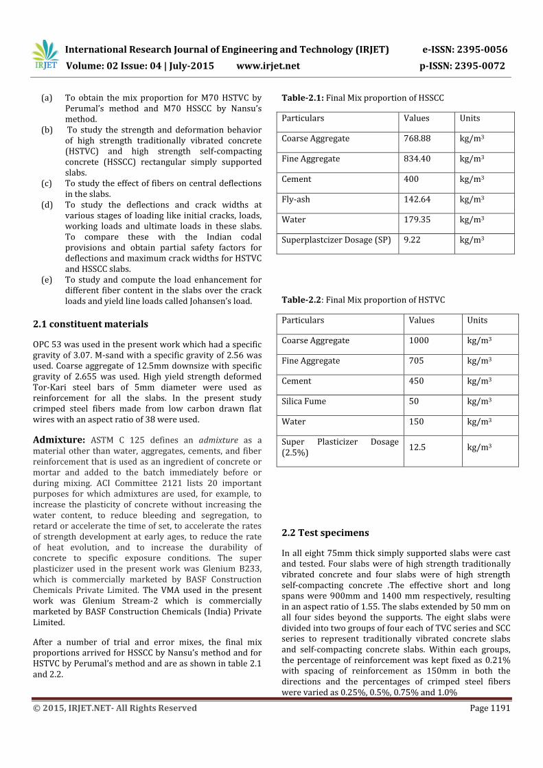
A typical layout of reinforcement for the slab is shown in fig 2.1.
Auxiliary specimens – In all three cubes of 100X100X100 mm,1 prism of size 75×75×450mm and 1 cylinder of 100 mm diameter and 200 mm height were cast along with each series of slabs to determine the compressive strength, flexural strength and the modulus of rupture.
Fig-2.1: Typical reinforcement cages of a slab
Fig -2.2: Auxiliary specimens for HSSCC and HSTVC 2.3 Instrumentation Suitable instrumentation was done to measure the following deformations of the slab. a. Vertical deflection b. Crack widths. a) Vertical deflection of the slab The vertical deflection of the slab was measured at the center, using a dial gauge having 75 mm travel and least count of 0.01 mm. The jacks were pre calibrated using suitable proving ring. Before the application of load, the position of dial gauge was checked and initial reading was taken. The load was then applied at an increment of 2 KN till first crack and then at an increment of 4 KN till failure of slab. The
deflection was recorded after allowing some time for the load to stabilize. After the development of cracks, the locations of cracks and the maximum crack widths were noted. During recording of readings the load was maintained by pumping when required. The loading process was usually stopped, when deflections became considerable and/or the reinforcement snapped with a loud noise. b) Crack width measurement As and when the cracks developed due to sustained loading on the slabs, these cracks started developing on the tension faces of slabs. The widths of the cracks developed were then measured using a microscope which had a least count of 0.1mm. These were recorded for then indicated loads at regular intervals. 2.4 Casting and curing of slabs Mix proportions: The mixes used were of high strength traditionally vibrated concrete and self-compacting concrete with a strength of M70. Mould : The slabs were cast on a ply wood surface, and only side shuttering of requisite height was made of 2 mild steel equal angle of size 50mmX 50mm X 4mm which were welded to give a dimension of 75 X 50 X 4 and was painted with metal primer and two coats of enamel paint. Making of concrete and casting: All the materials were weighed and kept ready before mixing was started. The fine aggregate and cement were mixed together, until a uniform color was achieved. Then the coarse aggregate was added to this mixture and later steel fibers were added and the dry materials were properly mixed. Water was added at this stage and mixed and finally Superplastcizer was added and the concrete was mixed thoroughly, until the resulting concrete was uniform in appearance. In the Mould of the slab, plastic cover blocks were used to give an effective cover of 10 mm. The reinforcement grid was then placed and a layer of concrete was spread just to cover the reinforcement and well compacted using needle vibrator in case of traditionally vibrated concrete. The concreting was continued in layers; till the full slab was concreted. Along with the casting of slab, auxiliary specimens were cast. The top of the slab was finished smooth with a straight edge. The auxiliary specimens were leveled with a trowel.
International Research Journal of Engineering and Technology (IRJET) e-ISSN: 2395-0056
Volume: 02 Issue: 04 | July-2015 www.irjet.net p-ISSN: 2395-0072
© 2015, IRJET.NET- All Rights Reserved Page 1193
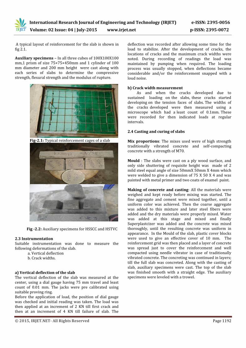
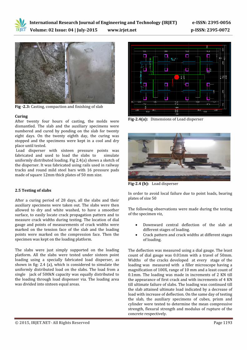
Fig -2.3: Casting, compaction and finishing of slab Curing After twenty four hours of casting, the molds were dismantled. The slab and the auxiliary specimens were numbered and cured by ponding on the slab for twenty eight days. On the twenty eighth day, the curing was stopped and the specimens were kept in a cool and dry place until tested. Load disperser with sixteen pressure points was fabricated and used to load the slabs to simulate uniformly distributed loading. Fig 2.4(a) shows a sketch of the disperser. It was fabricated using rails used in railway tracks and round mild steel bars with 16 pressure pads made of square 12mm thick plates of 50 mm size.
2.5 Testing of slabs
After a curing period of 28 days, all the slabs and their auxiliary specimens were taken out. The slabs were then allowed to dry and white washed, to have a smoother surface, to easily locate crack propagation pattern and to measure crack widths during testing. The location of dial gauge and points of measurements of crack widths were marked on the tension face of the slab and the loading points were marked on the compression face. Then the specimen was kept on the loading platform.
The slabs were just simply supported on the loading platform. All the slabs were tested under sixteen point loading using a specially fabricated load disperser, as shown in fig: 2.4 (a), which is considered to simulate the uniformly distributed load on the slabs. The load from a single jack of 500kN capacity was equally distributed to the loading through load dispenser via. The loading area was divided into sixteen equal areas.
Fig-2.4(a): Dimensions of Load disperser
Fig-2.4 (b): Load disperser In order to avoid local failure due to point loads, bearing plates of size 50
The following observations were made during the testing of the specimen viz,
Downward central deflection of the slab at different stages of loading.
Crack pattern and crack widths at different stages of loading.
The deflection was measured using a dial gauge. The least count of dial gauge was 0.01mm with a travel of 50mm. Widths of the cracks developed at every stage of the loading was measured with a filler microscope having a magnification of 100X, range of 10 mm and a least count of 0.1mm. The loading was made in increments of 2 KN till the appearance of first crack and with increments of 4 KN till ultimate failure of slabs. The loading was continued till the slab attained ultimate load indicated by a decrease of load with increase of deflection. On the same day of testing the slab, the auxiliary specimens of cubes, prism and cylinder were tested to determine the mean compressive strength, flexural strength and modulus of rupture of the concrete respectively.
International Research Journal of Engineering and Technology (IRJET) e-ISSN: 2395-0056
Volume: 02 Issue: 04 | July-2015 www.irjet.net p-ISSN: 2395-0072
© 2015, IRJET.NET- All Rights Reserved Page 1194
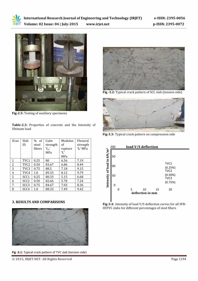
Fig-2.5: Testing of auxiliary specimens Table-2.3: Properties of concrete and the Intensity of Ultimate load Sl.no Slab
ID % of steel fibers
Cube strength ‘fcu’ MPa
Modulus of rupture ‘fr’ MPa
Flexural strength ‘fb’ MPa
1 TVC1 0.25 80 6.56 7.19 2 TVC2 0.50 83.67 6.86 8.49 3 TVC3 0.75 88.5 7.18 9.15 4 TVC4 1.0 89.33 8.12 9.79 5 SCC1 0.25 80.33 5.15 6.68 6 SCC2 0.50 82.66 5.78 7.24 7 SCC3 0.75 84.67 7.03 8.36 8 SCC4 1.0 88.33 7.49 9.42
3. RESULTS AND COMPARISONS
Fig -3.1: Typical crack pattern of TVC slab (tension side)
Fig -3.2: Typical crack pattern of SCC slab (tension side)
Fig-3.3: Typical crack pattern on compression side
0
50
100
150
200
0 5 10 15 20
Inte
nsi
ty o
f lo
ad
in
kN
/m
2
deflection in mm
load V/S deflection
TVC1(0.25%)TVC2(0.50%)TVC3(0.75%)
Fig-3.4: Intensity of load V/S deflection curves for all SFR-HSTVC slabs for different percentages of steel fibers
International Research Journal of Engineering and Technology (IRJET) e-ISSN: 2395-0056
Volume: 02 Issue: 04 | July-2015 www.irjet.net p-ISSN: 2395-0072
© 2015, IRJET.NET- All Rights Reserved Page 1195
0
50
100
150
200
250
0 5 10 15 20Inte
nsi
ty o
f lo
ad
in
kN
/m
2
deflection in mm
load V/S deflection
SCC1(0.25%)SCC2(0.50%)SCC3(0.75%)
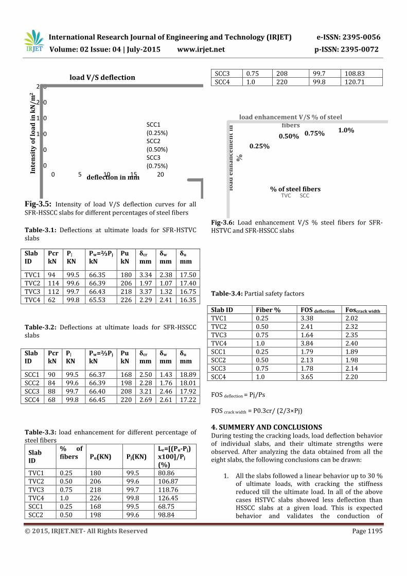
Fig-3.5: Intensity of load V/S deflection curves for all SFR-HSSCC slabs for different percentages of steel fibers
Table-3.1: Deflections at ultimate loads for SFR-HSTVC slabs
Slab ID
Pcr kN
PJ
KN Pw=⅔Pj
kN Pu kN
δcr mm
δw mm
δu mm
TVC1 94 99.5 66.35 180 3.34 2.38 17.50 TVC2 114 99.6 66.39 206 1.97 1.07 17.40 TVC3 112 99.7 66.43 218 3.37 1.32 16.75 TVC4 62 99.8 65.53 226 2.29 2.41 16.35
Table-3.2: Deflections at ultimate loads for SFR-HSSCC slabs
Slab ID
Pcr kN
PJ
KN Pw=⅔Pj
kN Pu kN
δcr mm
δw mm
δu mm
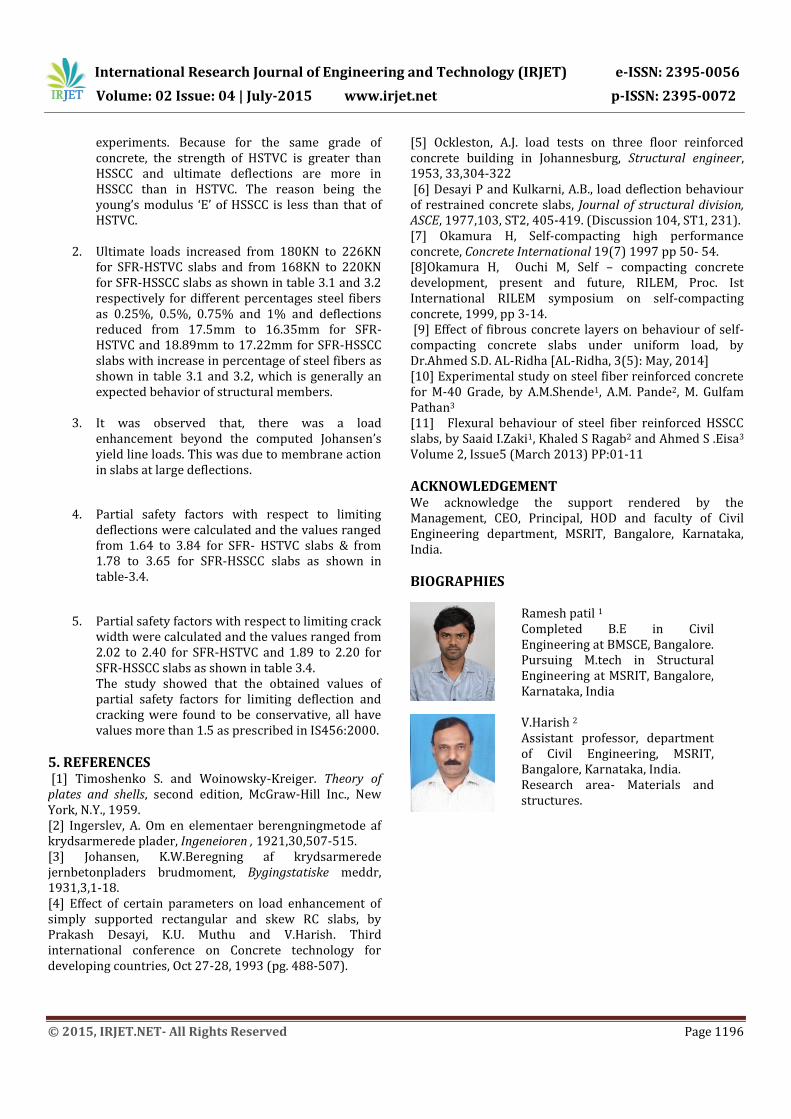
SCC1 90 99.5 66.37 168 2.50 1.43 18.89 SCC2 84 99.6 66.39 198 2.28 1.76 18.01 SCC3 88 99.7 66.40 208 3.21 2.46 17.92 SCC4 68 99.8 66.45 220 2.69 2.61 17.22 Table-3.3: load enhancement for different percentage of steel fibers
Slab ID
% of fibers Pu(KN) Pj(KN)
Le=[(Pu-Pj) x100]/Pj
(%) TVC1 0.25 180 99.5 80.86 TVC2 0.50 206 99.6 106.87 TVC3 0.75 218 99.7 118.76 TVC4 1.0 226 99.8 126.45 SCC1 0.25 168 99.5 68.75 SCC2 0.50 198 99.6 98.84
SCC3 0.75 208 99.7 108.83 SCC4 1.0 220 99.8 120.71
loa
d e
nh
an
cem
en
t in
%
load enhancement V/S % of steel fibers
TVC SCC
0.25%
0.50%1.0%0.75%
% of steel fibers
Fig-3.6: Load enhancement V/S % steel fibers for SFR-HSTVC and SFR-HSSCC slabs
Table-3.4: Partial safety factors Slab ID Fiber % FOS deflection Foscrack width
TVC1 0.25 3.38 2.02 TVC2 0.50 2.41 2.32 TVC3 0.75 1.64 2.35 TVC4 1.0 3.84 2.40 SCC1 0.25 1.79 1.89 SCC2 0.50 2.13 1.98 SCC3 0.75 1.78 2.14 SCC4 1.0 3.65 2.20
FOS deflection = Pj/Ps FOS crack width = P0.3cr/ (2/3×Pj)
4. SUMMERY AND CONCLUSIONS During testing the cracking loads, load deflection behavior of individual slabs, and their ultimate strengths were observed. After analyzing the data obtained from all the eight slabs, the following conclusions can be drawn:
1. All the slabs followed a linear behavior up to 30 % of ultimate loads, with cracking the stiffness reduced till the ultimate load. In all of the above cases HSTVC slabs showed less deflection than HSSCC slabs at a given load. This is expected behavior and validates the conduction of
International Research Journal of Engineering and Technology (IRJET) e-ISSN: 2395-0056
Volume: 02 Issue: 04 | July-2015 www.irjet.net p-ISSN: 2395-0072
© 2015, IRJET.NET- All Rights Reserved Page 1196
experiments. Because for the same grade of concrete, the strength of HSTVC is greater than HSSCC and ultimate deflections are more in HSSCC than in HSTVC. The reason being the young’s modulus ‘E’ of HSSCC is less than that of HSTVC.
2. Ultimate loads increased from 180KN to 226KN for SFR-HSTVC slabs and from 168KN to 220KN for SFR-HSSCC slabs as shown in table 3.1 and 3.2 respectively for different percentages steel fibers as 0.25%, 0.5%, 0.75% and 1% and deflections reduced from 17.5mm to 16.35mm for SFR-HSTVC and 18.89mm to 17.22mm for SFR-HSSCC slabs with increase in percentage of steel fibers as shown in table 3.1 and 3.2, which is generally an expected behavior of structural members.
3. It was observed that, there was a load
enhancement beyond the computed Johansen’s yield line loads. This was due to membrane action in slabs at large deflections.
4. Partial safety factors with respect to limiting deflections were calculated and the values ranged from 1.64 to 3.84 for SFR- HSTVC slabs & from 1.78 to 3.65 for SFR-HSSCC slabs as shown in table-3.4.
5. Partial safety factors with respect to limiting crack width were calculated and the values ranged from 2.02 to 2.40 for SFR-HSTVC and 1.89 to 2.20 for SFR-HSSCC slabs as shown in table 3.4. The study showed that the obtained values of partial safety factors for limiting deflection and cracking were found to be conservative, all have values more than 1.5 as prescribed in IS456:2000.
5. REFERENCES [1] Timoshenko S. and Woinowsky-Kreiger. Theory of plates and shells, second edition, McGraw-Hill Inc., New York, N.Y., 1959. [2] Ingerslev, A. Om en elementaer berengningmetode af krydsarmerede plader, Ingeneioren , 1921,30,507-515. [3] Johansen, K.W.Beregning af krydsarmerede jernbetonpladers brudmoment, Bygingstatiske meddr, 1931,3,1-18. [4] Effect of certain parameters on load enhancement of simply supported rectangular and skew RC slabs, by Prakash Desayi, K.U. Muthu and V.Harish. Third international conference on Concrete technology for developing countries, Oct 27-28, 1993 (pg. 488-507).
[5] Ockleston, A.J. load tests on three floor reinforced concrete building in Johannesburg, Structural engineer, 1953, 33,304-322 [6] Desayi P and Kulkarni, A.B., load deflection behaviour of restrained concrete slabs, Journal of structural division, ASCE, 1977,103, ST2, 405-419. (Discussion 104, ST1, 231). [7] Okamura H, Self-compacting high performance concrete, Concrete International 19(7) 1997 pp 50- 54. [8]Okamura H, Ouchi M, Self – compacting concrete development, present and future, RILEM, Proc. Ist International RILEM symposium on self-compacting concrete, 1999, pp 3-14. [9] Effect of fibrous concrete layers on behaviour of self-compacting concrete slabs under uniform load, by Dr.Ahmed S.D. AL-Ridha [AL-Ridha, 3(5): May, 2014] [10] Experimental study on steel fiber reinforced concrete for M-40 Grade, by A.M.Shende1, A.M. Pande2, M. Gulfam Pathan3 [11] Flexural behaviour of steel fiber reinforced HSSCC slabs, by Saaid I.Zaki1, Khaled S Ragab2 and Ahmed S .Eisa3
Volume 2, Issue5 (March 2013) PP:01-11
ACKNOWLEDGEMENT We acknowledge the support rendered by the Management, CEO, Principal, HOD and faculty of Civil Engineering department, MSRIT, Bangalore, Karnataka, India.
BIOGRAPHIES
Ramesh patil 1
Completed B.E in Civil Engineering at BMSCE, Bangalore. Pursuing M.tech in Structural Engineering at MSRIT, Bangalore, Karnataka, India
V.Harish 2
Assistant professor, department of Civil Engineering, MSRIT, Bangalore, Karnataka, India. Research area- Materials and structures.