Irfan training report 2
49
SAVERA GROUP OF INSTITUIONS MOHAMMAD IRFAN HAJAM Page 1 Sonalika Company profile Sonalika group started its journey of success during 1976 with foundation of small unit to fabricate and assemble wheat-harvesting machines .With passage of time this small initiative taken by Mittals in 1976 turns into a great success due to the continuous efforts of its promoters and thousands of employees who worked unaltered throughout. The success provided further motivation ultimately in resulting setting up new plant in the name of International Tractors Limited for the production of tractors as the demand requirement of which was growing at good pace. The plant which was setup at village Chak Gujran, Hoshiarpur and is spread over an area of 75 acres(approx.).And obtain the certificate of incorporation on 26 OCT in 1996.
-
Upload
irfanbinashraf -
Category
Engineering
-
view
83 -
download
1
Transcript of Irfan training report 2
SAVERA GROUP OF INSTITUIONS MOHAMMAD IRFAN HAJAM Page 1
Sonalika
Company profile
Sonalika group started its journey of success during 1976 with foundation of small unit to
fabricate and assemble wheat-harvesting machines .With passage of time this small initiative taken
by Mittals in 1976 turns into a great success due to the continuous efforts of its promoters and
thousands of employees who worked unaltered throughout.
The success provided further motivation ultimately in resulting setting up new plant in the
name of International Tractors Limited for the production of tractors as the demand requirement of
which was growing at good pace. The plant which was setup at village Chak Gujran, Hoshiarpur and
is spread over an area of 75 acres(approx.).And obtain the certificate of incorporation on 26 OCT in
1996.
SAVERA GROUP OF INSTITUIONS MOHAMMAD IRFAN HAJAM Page 2
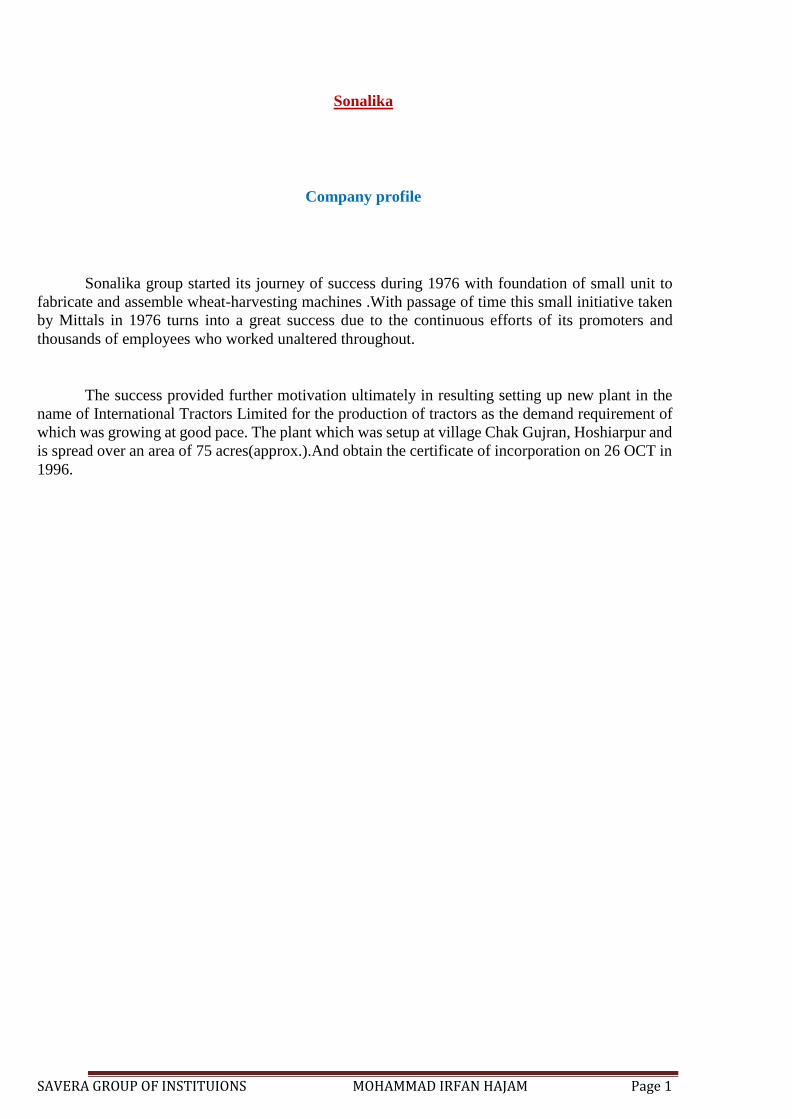
Fig No: 1 Parts Manufactured By Company
International Tractors Limited was incorporated on Oct 17, 1995.it was established on 1996-
97.now Feb.-march, the production rate of tractors 180 per day. The total no. Employees
working in ITL are more than 3000.the total no. of dealers of ITL in India and neighbouring
countries are 548. ITL was introduced 15 models of tractors .There are 5 regional office in India
which are at Delhi, Patna, Ahmadabad, Manipur and Bhopal. Company got ISO 9001- 2000
certificate in April 1999 by ICL. Company is also running its own agriculture equipment making
industry, which is producing threshers, disc harrow, wheat harvesters etc. Company also got
ISO
14001 –
1996 certificate for environmental safety and ISO TS 16949 for selfmading body parts &
plastic parts of tractor.
Group vision
SONALIKA GROUP COMPANIES
INTERNATIONAL TRACTORS LTD.
DG Sets
Cranes
Transmission
assembly
Tractor
Engines
SONALIKA AGRO INDUSTRIES
Agricultural
Machinery
Farm
Equipment
Magma
ITL .
Tractor
finance.
SAVERA GROUP OF INSTITUIONS MOHAMMAD IRFAN HAJAM Page 3
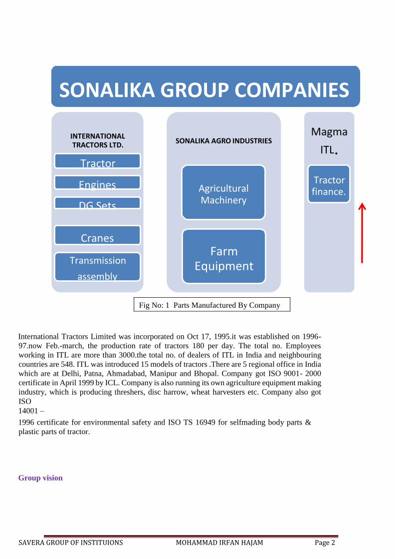
To become the world leading tractors manufacturing company and major player in automotive
products and services.
Company Mission
To translate vision into reality. Success
factor
• Quick decision making
• Innovation and strong R&D
• High degree of competency
• Resultant experience
• Fast adaptability to changes
• Product range
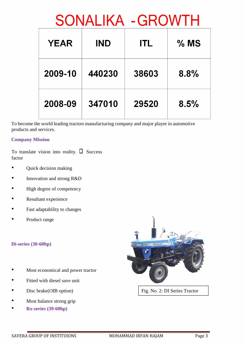
Di-series (30-60hp)
• Most economical and power tractor
• Fitted with diesel save unit
• Disc brake(OIB option)
• Most balance strong grip
• Rx-series (39-60hp)
Fig. No. 2: DI Series Tractor
SAVERA GROUP OF INSTITUIONS MOHAMMAD IRFAN HAJAM Page 4
• Modern tractor
• Available in different option of OIB ,power steering, turbo charger dual clutch DC valve
• Constant mesh gear box,
• Aerodynamic bonnet
• Mobile charger
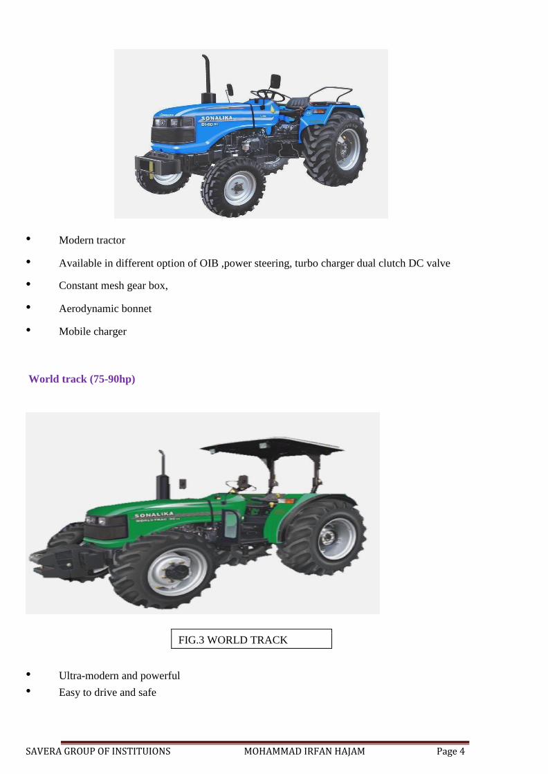
World track (75-90hp)
FIG.3 WORLD TRACK
• Ultra-modern and powerful
• Easy to drive and safe
SAVERA GROUP OF INSTITUIONS MOHAMMAD IRFAN HAJAM Page 5
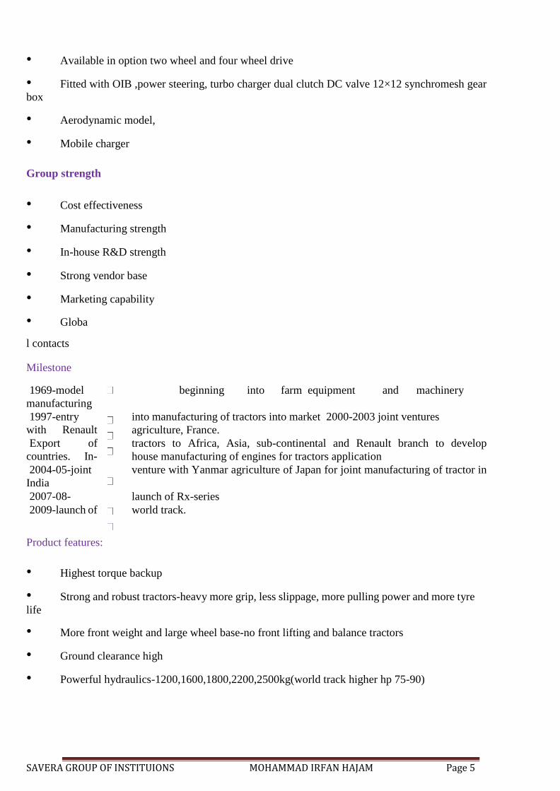
• Available in option two wheel and four wheel drive
• Fitted with OIB ,power steering, turbo charger dual clutch DC valve 12×12 synchromesh gear
box
• Aerodynamic model,
• Mobile charger
Group strength
• Cost effectiveness
• Manufacturing strength
• In-house R&D strength
• Strong vendor base
• Marketing capability
• Globa
l contacts
Milestone
1969-model beginning into farm equipment and machinery
manufacturing
1997-entry into manufacturing of tractors into market 2000-2003 joint ventures
with Renault agriculture, France.
Export of tractors to Africa, Asia, sub-continental and Renault branch to develop
countries. In- house manufacturing of engines for tractors application
2004-05-joint venture with Yanmar agriculture of Japan for joint manufacturing of tractor in
India
2007-08- launch of Rx-series
2009-launch of world track.
Product features:
• Highest torque backup
• Strong and robust tractors-heavy more grip, less slippage, more pulling power and more tyre
life
• More front weight and large wheel base-no front lifting and balance tractors
• Ground clearance high
• Powerful hydraulics-1200,1600,1800,2200,2500kg(world track higher hp 75-90)

SAVERA GROUP OF INSTITUIONS MOHAMMAD IRFAN HAJAM Page 6
PLANT VISIT
During the co-op term we were frequently taken for industrial visits with Mr.Rishiraj sir.
Each and every part of the industry was explored. During the visits the local workers told us that
thirty-three years ago we saw a dream that we have worked to fulfil relentlessly. This dream was 'to
make possible the total mechanization of Indian agriculture, so that Indian farmers can also stand on
the forefront of the world in terms of productivity and technology. Our dream has been to give them
a new future, full of new hopes and challenges. Challenges, that Sonalika will help every farmer
meet .It is this inspiration that has encouraged us to achieve a new every moment.
The lush green world of Indian agriculture is not new to Sonalika. The actuality is that
Sonalika has spent so much time on Indian farms that it understands the needs and aspirations of the
Indian farmer in there.
The saga started thirty-three years ago when Sonalika began manufacturing threshers to help
Indian farmers ensure greater productivity through qualitatively superior technology. History stands
witness that, since the day of its inception, Sonalika has never needed to look back. Today Sonalika
is a well-known name in every household. A great bond of trust has grown between the company
and farmers. Over the years, this trust grew to such an extent that the farmers soon put forth the
demand that Sonalika should also manufacture a high-technology tractor. For quite some time, the
company had also been thinking on the same lines and we took a bold step forward by beginning the
tractor production in 1995.
“Excellent Design" of Sonalika Tractor is prepared by Govt. of India's Central Mechanical
Research Institute. The design of Sonalika Tractor has been prepared by Central Mechanical
Engineering Research Institute (Durgapur), the premier design institute of the Government of India's
Research and Development department. The institute, which has also prepared the design of Swaraj
Tractor, is known for its three decades of designing experience.
The Technical Collaborators of I.T.L is with the Renault Agriculture, France. It has always
been the Sonalika's endeavour to offer Indian farmers international quality equipment, to enable
them to march in step with the developed world towards a brighter tomorrow.
World-class technology not only gives tractors greater power, but also helps in reducing the
consumption of diesel and making the tractor's engine environmentfriendly. With these aspects, and
the needs of the Indian farming community in mind, Sonalika entered into a technical collaboration
agreement with world leaders, Renault Agriculture of France. As a result of this joint effort, Sonalika
has developed the world class Euro-ii range at its fully automated plant at Hoshiarpur.
The inspiring objective has been to take Indian agriculture to the threshold of
a new beginning and empower the Indian agriculturist with the glory of a lush green new era.
Production Process
Every Sonalika tractor, manufactured at Sonalika’s ultra-modern plant at Hoshiarpur, is an
example of unmatched workmanship. At every stage of production experts keep a constant eye on
the minutest manufacturing details to ensure faultless quality control, by applying the most stringent
SAVERA GROUP OF INSTITUIONS MOHAMMAD IRFAN HAJAM Page 7
international quality-check standards to produce tractors that are unbeatable in their category. Each
part of every tractor is tested for operational excellence at the Hoshiarpur plant.
Sonalika Engine Production
This is where the top quality, smoke-free engines of Sonalika tractors are produced. The
engine is the most vital component of a tractor and therefore only the latest imported equipment is
used at the plant to ensure that the engine of every Sonalika tractor is of truly world class standard.
It is this attention to detail that enables Sonalika engine to lead the way, when it comes to
fuel-economy and power' To maintain quality levels, every engine is also thoroughly tested on
computerized machines after being manufactured.
Gear Manufacturing Process
Only the finest technology and equipment is used to manufacture international quality
gearboxes at Sonalika fully equipped gear manufacturing unit. One of the most modern units of its
kind, it uses equipment that has been especially imported from France, Germany and Russia to
provide gears extra strength and operational efficiency.
Quality Check of Gear Boxes
Every gearbox of Sonalika is intensively tested for quality during the manufacturing process
itself. Done by using the latest computerized equipment, the quality control system ensures that every
gearbox is manufactured according to internationally accepted quality standards.
Quality Check
To guarantee that Sonalika tractors match the most stringent international quality norms, the
Quality Control Unit of the plant checks the production process and every component used in
production, most intensively. No room is left for even the smallest error. The precision tests have the
capacity to do a quality scan on an area as small as a
1000th
part of 7mm. This is the reason why every Sonalika tractor is an example of world class quality'
Working in the assembling line
After all this hard work done in the workshop and the field trips, we were moved into the
assembling line where the new tractors were assembled. We spend nearly one hour in the assembly
line of I.T.L. One thing that we came to know that perfection does not come in a day
SAVERA GROUP OF INSTITUIONS MOHAMMAD IRFAN HAJAM Page 8
you will have to work and work hard for it. Seeing the workers move their hands we were astonished
as they were moving them very fast as if the position of the target was fit in their mind like a machine.
Overall I had good time assembling tractors in the assembly line.
What is a Tractor?
• The word Tractor is derived from the word Traction Motor.(tract+or=tractor). Traction is the force in the direction of travel developed by the traction medium (soil) & is transferred to the tractor.
• A Tractor is a vehicle specifically designed to deliver a high pulling force at slow speeds, for
the purpose of hauling a trailer or an implement used in agriculture.
• The power developed by the engine, finally goes to the tractor wheels, which moves the tractor
with or without load.
• Torque is more important for the functioning of Tractor.
• Speed is secondary factor.
SAVERA GROUP OF INSTITUIONS MOHAMMAD IRFAN HAJAM Page 9
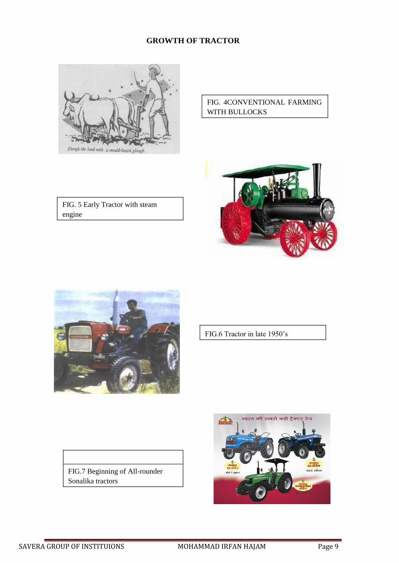
GROWTH OF TRACTOR
FIG. 4CONVENTIONAL FARMING
WITH BULLOCKS
FIG. 5 Early Tractor with steam
engine
FIG.7 Beginning of All-rounder
Sonalika tractors
FIG.6 Tractor in late 1950’s
SAVERA GROUP OF INSTITUIONS MOHAMMAD IRFAN HAJAM Page 10
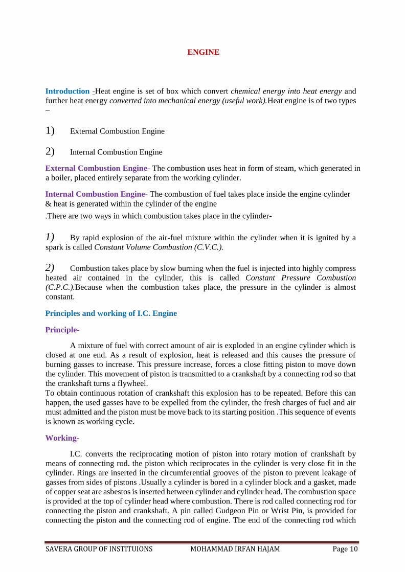
ENGINE
Introduction -Heat engine is set of box which convert chemical energy into heat energy and
further heat energy converted into mechanical energy (useful work).Heat engine is of two types
–
1) External Combustion Engine
2) Internal Combustion Engine
External Combustion Engine- The combustion uses heat in form of steam, which generated in
a boiler, placed entirely separate from the working cylinder.
Internal Combustion Engine- The combustion of fuel takes place inside the engine cylinder
& heat is generated within the cylinder of the engine
.There are two ways in which combustion takes place in the cylinder-
1) By rapid explosion of the air-fuel mixture within the cylinder when it is ignited by a
spark is called Constant Volume Combustion (C.V.C.).
2) Combustion takes place by slow burning when the fuel is injected into highly compress
heated air contained in the cylinder, this is called Constant Pressure Combustion
(C.P.C.).Because when the combustion takes place, the pressure in the cylinder is almost
constant.
Principles and working of I.C. Engine
Principle-
A mixture of fuel with correct amount of air is exploded in an engine cylinder which is
closed at one end. As a result of explosion, heat is released and this causes the pressure of
burning gasses to increase. This pressure increase, forces a close fitting piston to move down
the cylinder. This movement of piston is transmitted to a crankshaft by a connecting rod so that
the crankshaft turns a flywheel. To obtain continuous rotation of crankshaft this explosion has to be repeated. Before this can
happen, the used gasses have to be expelled from the cylinder, the fresh charges of fuel and air
must admitted and the piston must be move back to its starting position .This sequence of events
is known as working cycle.
Working-
I.C. converts the reciprocating motion of piston into rotary motion of crankshaft by
means of connecting rod. the piston which reciprocates in the cylinder is very close fit in the
cylinder. Rings are inserted in the circumferential grooves of the piston to prevent leakage of
gasses from sides of pistons .Usually a cylinder is bored in a cylinder block and a gasket, made
of copper seat are asbestos is inserted between cylinder and cylinder head. The combustion space
is provided at the top of cylinder head where combustion. There is rod called connecting rod for
connecting the piston and crankshaft. A pin called Gudgeon Pin or Wrist Pin, is provided for
connecting the piston and the connecting rod of engine. The end of the connecting rod which
SAVERA GROUP OF INSTITUIONS MOHAMMAD IRFAN HAJAM Page 11
fits over the gudgeon pin is called small end of connecting rod. The other end which fits over
the crankpin is called Big End of Connecting Rod. The crankshaft rotates in main bearing which
are fitted in the crankcase. A flywheel is provided at one end of the crankshaft for smoothening
the uneven torque, produced by a engine. There is an oil sump at the bottom of the engine which
contains lubricating oil for lubricating of different parts of the engine. Mechanical cycles of
internal combustion engine can be completed in two ways-
1) When the cycle is completed in two regulation of the crankshaft it is called four stroke
cycle engine.
2) When the cycle is completed in one regulation of the crankshaft it is called two stroke
cycle engine.
Engine Function: To provide power for functioning of all the aggregates of tractor.
SAVERA GROUP OF INSTITUIONS MOHAMMAD IRFAN HAJAM Page 12
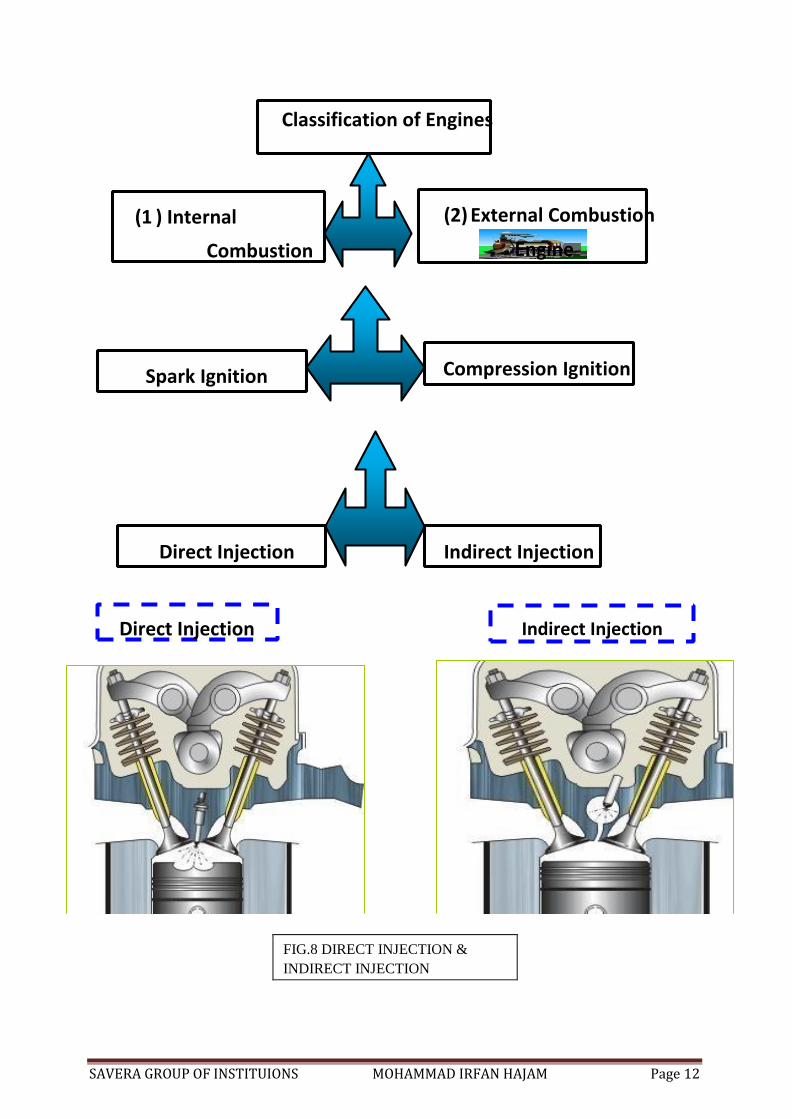
FIG.8 DIRECT INJECTION &
INDIRECT INJECTION
(1 ) Internal
Combustion
(2) External Combustion
Engine
Classification of Engines
Spark Ignition Compression Ignition
Direct Injection Indirect Injection
Direct Injection Indirect Injection
SAVERA GROUP OF INSTITUIONS MOHAMMAD IRFAN HAJAM Page 13
Advantages of DI Engine:
• Burning is more uniform
• Power developed is high
• Efficiency is high
• Low smoke value
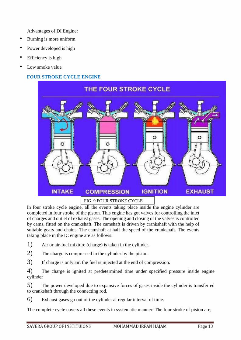
FOUR STROKE CYCLE ENGINE
FIG. 9 FOUR STROKE CYCLE
In four stroke cycle engine, all the events taking place inside the engine cylinder are
completed in four stroke of the piston. This engine has got valves for controlling the inlet
of charges and outlet of exhaust gases. The opening and closing of the valves is controlled
by cams, fitted on the crankshaft. The camshaft is driven by crankshaft with the help of
suitable gears and chains. The camshaft at half the speed of the crankshaft. The events
taking place in the IC engine are as follows:
1) Air or air-fuel mixture (charge) is taken in the cylinder.
2) The charge is compressed in the cylinder by the piston.
3) If charge is only air, the fuel is injected at the end of compression.
4) The charge is ignited at predetermined time under specified pressure inside engine
cylinder
5) The power developed due to expansive forces of gases inside the cylinder is transferred
to crankshaft through the connecting rod.
6) Exhaust gases go out of the cylinder at regular interval of time.
The complete cycle covers all these events in systematic manner. The four stroke of piston are;
SAVERA GROUP OF INSTITUIONS MOHAMMAD IRFAN HAJAM Page 14
1) Suction Stroke
2) Compression Stroke
3) Power Stroke
4) Exhaust Stroke
1)Suction Stroke- During suction stroke, only air are mixture of air & fuel are drawn inside the
cylinder. The charge enters the engine through the inlet valve which remains open during
admission of the charge. The exhaust valve remains close during this stroke. The pressure in the
engine cylinder is less then atmospheric pressure during this stroke.
2)Compression stroke- The charge taken in the cylinder is compressed by the piston during
this stroke. The entire charge of the cylinder is compressed to a small volume contained in the
clearance volume of the cylinder. If only air is compressed in the cylinder (as in case of diesel
engine), the fuel is ignited at the end compression stroke. The ignition takes place due to high
pressure and temperature. After ignition tremendous amount of heat is generated causing very
high pressure which pushes the piston backward for useful work. Both valves are closed during
this stroke.
3)Power Stroke- During power stroke, the high pressure developed due to combustion of fuel
causes the piston to be forced forward or backward at regular intervals. The connecting rods
with the help of crankshaft transmit the power to the transmission system for useful work. Both
valves are closed during this stroke.
4)Exhaust Stroke- Exhaust gases go out through exhaust valves during this stroke .All the burnt
gases go out of engine and the cylinder becomes ready to receive fresh charge. The inlet valve
is closed and exhaust valves remains open.
Thus it is found that out of four stroke, there is only one power stroke three idle strokes. The
power stroke supplies necessary momentum for useful work.
TWO STROKE CYCLE ENGINE-
In such engine, the whole sequence of events i.e. suction, compression, power &
exhaust are completed in two strokes of the piston and one complete revolution of the crankshaft.
There is no valve in this type of engine. Gas movement takes place through holes called ports
in the cylinder. The crankcase of the engine is gas tight in which crankshaft rotates.
1) First stroke (Suction + compression) – When the piston moves up the cylinder it covers to
of ports, the exhaust port and the transfer port which are normally almost opposite to each other.
This traps a charge of fresh mixture in the cylinder and further upward movement of the piston
compresses this charge. Further movement of piston also uncovers a third port in the cylinder
suction port .More fresh mixture is drawn through this port into the crankcase. Just before the
end of this stroke the mixture in the cylinder is ignited as in the four stroke cycle.
2)Second Stroke (Power + Exhaust) - The rise in pressure in the cylinder cause by the burning
gases forces the piston to move down the cylinder. When the piston goes down it covers and
closes the suction port, trapping the mixture drawn into the crankcase during previous stroke then
SAVERA GROUP OF INSTITUIONS MOHAMMAD IRFAN HAJAM Page 15
compressing it. Further downward movement of the piston uncovers first the exhaust port and
then transfer port. This allows the burnt gases to flow of through exhaust port and also fresh
mixture under pressure in the crankcase is transferred into the cylinder When the piston at the top
of its stroke, it is said to be at the top dead centre(TDC).When the piston is at the bottom of its
stroke, it is said to be at its bottom dead centre(BDC).
SCAVENGING- The process of removal of burnt or exhaust gases from the engine cylinder is
known as scavenging.
Diesel Engine (Compression Ignition Engine)-
Special Features-
1) Engine has high compression ratio ranging from 14:1 to 22:1
2) During compression stroke the engine attains high pressure ranging from 30 to 45 kg/cm2
and high temperature of about 500°c.
3) At the end of compression stroke, fuel is ignited into the cylinder through injectors
(atomisers) at a very high pressure ranging from 120 to 200 kg/cm2
.
4) Ignition takes place due to heat of compression only.
5) There is no external spark in diesel engine.
6) Diesel engine has better slogging or lugging ability i.e. its maintains high torque for a
longer duration of time at a lower speed.
Engine Components –
Internal combustion engine consist of a no of parts which are given below:
1) Cylinder – it is a part of engine which confines the expanding gases and forms the
combustion space. It is basis part of engine. Cylinder is usually made of high grade cast iron.
2) Cylinder Block – it is a solid casting which include the cylinder and water jackets
(cooling fins in the air cooled engines).
3) Cylinder Head – it is a detachable portion of an engine which covers the engine and
includes the combustion chamber, spark plugs and valves.
4) cylinder Liner Or Sleeves- it is a cylindrical lining either wet or dry which is inserted
in the cylinder block in which the piston slides. Cylinder liners are fitted in the cylinder bore
and they are easily replaceable. Liners are classified as:
i) Dry liners makes metal to metal contacts with cylinder block casting.
ii) Wet liners come in contacts with the cooling water.

SAVERA GROUP OF INSTITUIONS MOHAMMAD IRFAN HAJAM Page 16
5) Piston- it is cylindrical part closed at one end which maintains a close sliding fit in the engine cylinder. It is connected to connecting rod by a piston. Cast iron is used for making
piston.
Head (crown) of piston – it is the top of piston.
Skirt- it is that portion of the piston below the piston pin which is designed to absorb the side
movements of piston.
6) Piston Ring – it is a split expansion ring, placed in the groove of the piston. Piston ring
is fitted in the grooves, made in the piston. They are usually made of cast iron or pressed steel
alloy. The functions of the ring are as follows:
i) It forms a gas tight combustion chamber for all position of piston. ii) It reduces contact area
between cylinder wall & piston wall for preventing friction losses and excessive wear.
iii) It controls the cylinder lubrication. iv) It transmits the heat away from the piston to the
cylinder walls. Piston rings are of two types:
a) Compression Ring or Piston Ring
b) Oil Ring (Oil scraper ring)
7) Piston Pins- it is also called as wrist pins or gudgeon pin. Piston pin is used to join the
connecting rod to the piston. It is usually made of case hardened alloy steel.
8) Connecting Rod – It is a special type of rod, one end of which is attached to the piston
and the other end to the crankshaft .It transmits the power of combustion to the crankshaft and
makes it rotate continuously. It is usually made of drop forged steel.
9) Crankshaft- it is the main shaft of an engine which converts reciprocating motion of the
piston into rotary motion of flywheel. Crankshaft is made of drop forged steel or cast steel. The
space that support the crankshaft in the cylinder block is called main journal, whereas the part
to which connecting rod is attached is known as crank journal.
10) Fly wheel - It is made of cast iron. Its main function is as follows:
(a) Its stores energy during power stroke & returns back the same energy during the idle
strokes.
(b) It also carries ring gear that meshes with the pinion of the starting motor.
(c) The rear surface of the flywheel serves as one of the pressure surfaces for the clutch plate.
(d) Engine timing marks are usually stamped on the flywheel, which helps in adjusting the
timing of the engine.
SAVERA GROUP OF INSTITUIONS MOHAMMAD IRFAN HAJAM Page 17
11) Crankcase- It is that part of engine which support and encloses the crankshaft &
camshaft. It provides reservoir for the lubricating oil of the engine. It also serves as a mounting
unit for such accessories as the oil pump, oil filter, generator, starting motor, ignition components.
12) Camshaft- it is a shaft which raises and lowers the inlet and exhaust valve at proper time
.Camshaft is driven by crankshaft by means of gears ,chains or sprockets. The speed of camshaft
is exactly half the speed of crankshaft in four stroke engine.
Timing Gear- It is a common the end of the combination of gears, one gears of which is
mounted at one end of the camshaft and the other gear on the end of the crankshaft .Camshaft
gear is bigger in side than that of crankshaft gear and it has twice as many teeth as that of
crankshaft gear. Timing gear controls the timing of ignition, timing of opening and closing of
valves as well as fuel injection timing.
13) Inlet manifold- It is that part of engine through which air or air- fuel mixture enters into
the engine cylinder.
14) Exhaust manifold- It is that part of engine through which exhaust gases go out of engine
cylinder. It is capable of withstanding high temperature of burnt gases.
15) Valve- It is a small mechanical device used for opening & closing the passage leading to
the engine cylinder. Main parts are below:
Valve Head, Valve stem, Valve seat, Valve stem guide
16) Tappet- Tappet is also called as valve lifter. Tappet raises or lowers the valves.
17) Rocker arm- It is an arm used to change upward motion of push rod to downward motion
for opening an engine valve.
Basics system in An Engine :
1. Air Intake System
2. Exhaust System
3. Cooling System
4. Lubrication System
5. Fuel Injection System
1.) Air Intake System -
Function: - To provides clean & requisite quantity of air to engine for better combustion.
Types: -
1. Naturally aspirated.
2. Force Feed Intake System (Turbo charging
SAVERA GROUP OF INSTITUIONS MOHAMMAD IRFAN HAJAM Page 18
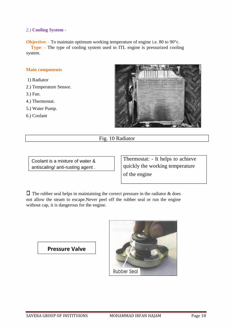
2.) Cooling System -
Objective: - To maintain optimum working temperature of engine i.e. 80 to 90°c.
Type: - The type of cooling system used in ITL engine is pressurized cooling
system.
Main components
1) Radiator
2.) Temperature Sensor.
3.) Fan.
4.) Thermostat.
5.) Water Pump.
6.) Coolant
Fig. 10 Radiator
The rubber seal helps in maintaining the correct pressure in the radiator & does
not allow the steam to escape.Never peel off the rubber seal or run the engine
without cap, it is dangerous for the engine.
Thermostat: - It helps to achieve
quickly the working temperature
of the engine
Coolant is a mixture of water &
antiscaling/ anti-rusting agent .
Pressure Valve
SAVERA GROUP OF INSTITUIONS MOHAMMAD IRFAN HAJAM Page 19
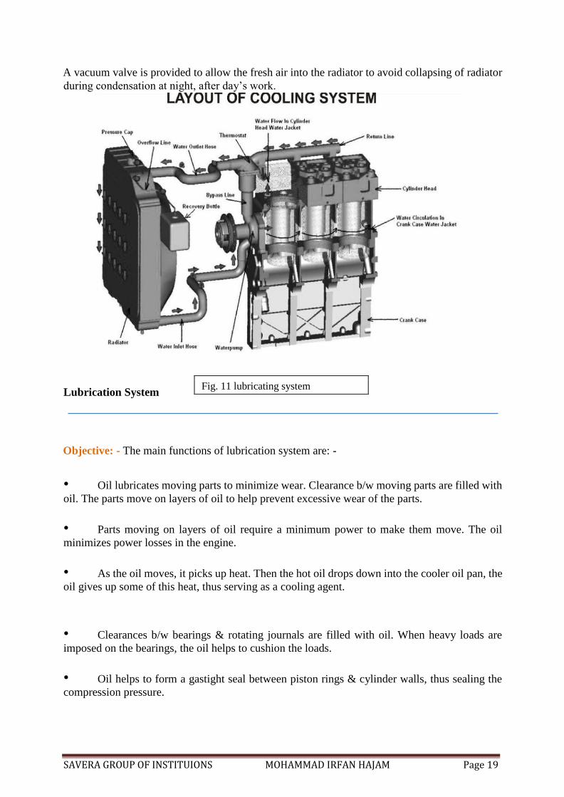
A vacuum valve is provided to allow the fresh air into the radiator to avoid collapsing of radiator
during condensation at night, after day’s work.
Lubrication System
Objective: - The main functions of lubrication system are: -
• Oil lubricates moving parts to minimize wear. Clearance b/w moving parts are filled with
oil. The parts move on layers of oil to help prevent excessive wear of the parts.
• Parts moving on layers of oil require a minimum power to make them move. The oil
minimizes power losses in the engine.
• As the oil moves, it picks up heat. Then the hot oil drops down into the cooler oil pan, the
oil gives up some of this heat, thus serving as a cooling agent.
• Clearances b/w bearings & rotating journals are filled with oil. When heavy loads are
imposed on the bearings, the oil helps to cushion the loads.
• Oil helps to form a gastight seal between piston rings & cylinder walls, thus sealing the
compression pressure.
Fig. 11 lubricating system
SAVERA GROUP OF INSTITUIONS MOHAMMAD IRFAN HAJAM Page 20
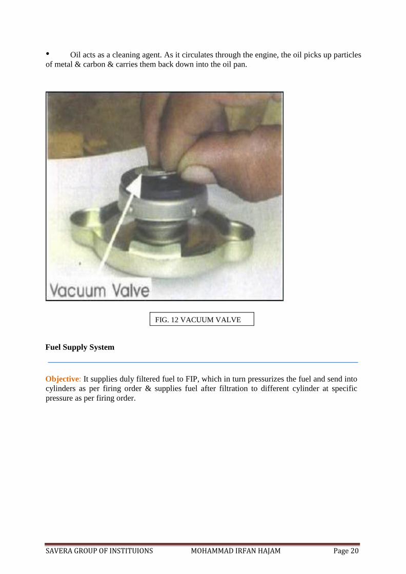
• Oil acts as a cleaning agent. As it circulates through the engine, the oil picks up particles
of metal & carbon & carries them back down into the oil pan.
FIG. 12 VACUUM VALVE
Fuel Supply System
Objective: It supplies duly filtered fuel to FIP, which in turn pressurizes the fuel and send into
cylinders as per firing order & supplies fuel after filtration to different cylinder at specific
pressure as per firing order.
SAVERA GROUP OF INSTITUIONS MOHAMMAD IRFAN HAJAM Page 21
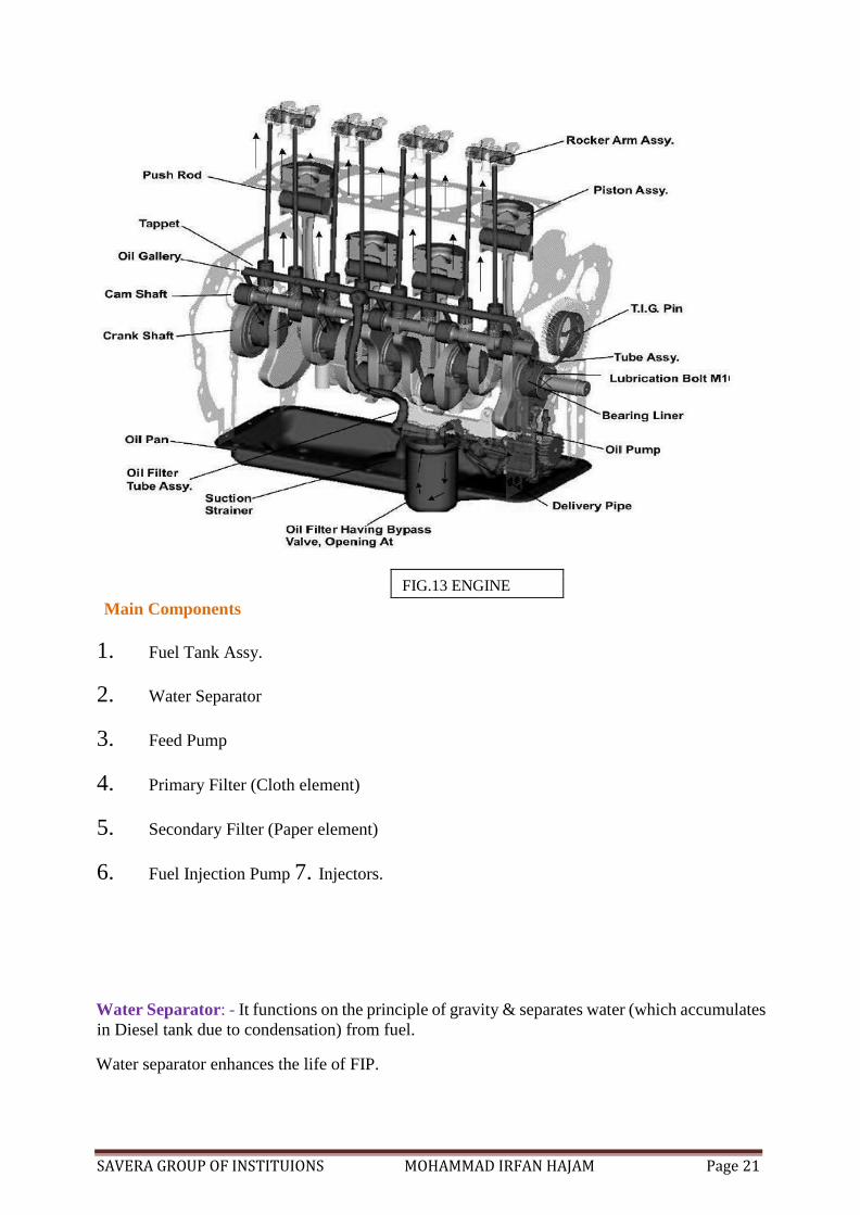
FIG.13 ENGINE
Main Components
1. Fuel Tank Assy.
2. Water Separator
3. Feed Pump
4. Primary Filter (Cloth element)
5. Secondary Filter (Paper element)
6. Fuel Injection Pump 7. Injectors.
Water Separator: - It functions on the principle of gravity & separates water (which accumulates
in Diesel tank due to condensation) from fuel.
Water separator enhances the life of FIP.
SAVERA GROUP OF INSTITUIONS MOHAMMAD IRFAN HAJAM Page 22
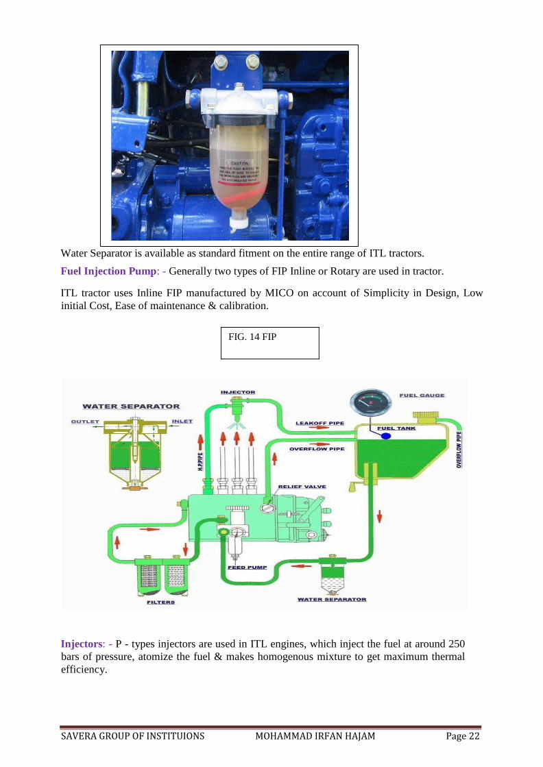
Water Separator is available as standard fitment on the entire range of ITL tractors.
Fuel Injection Pump: - Generally two types of FIP Inline or Rotary are used in tractor.
ITL tractor uses Inline FIP manufactured by MICO on account of Simplicity in Design, Low
initial Cost, Ease of maintenance & calibration.
FIG. 14 FIP
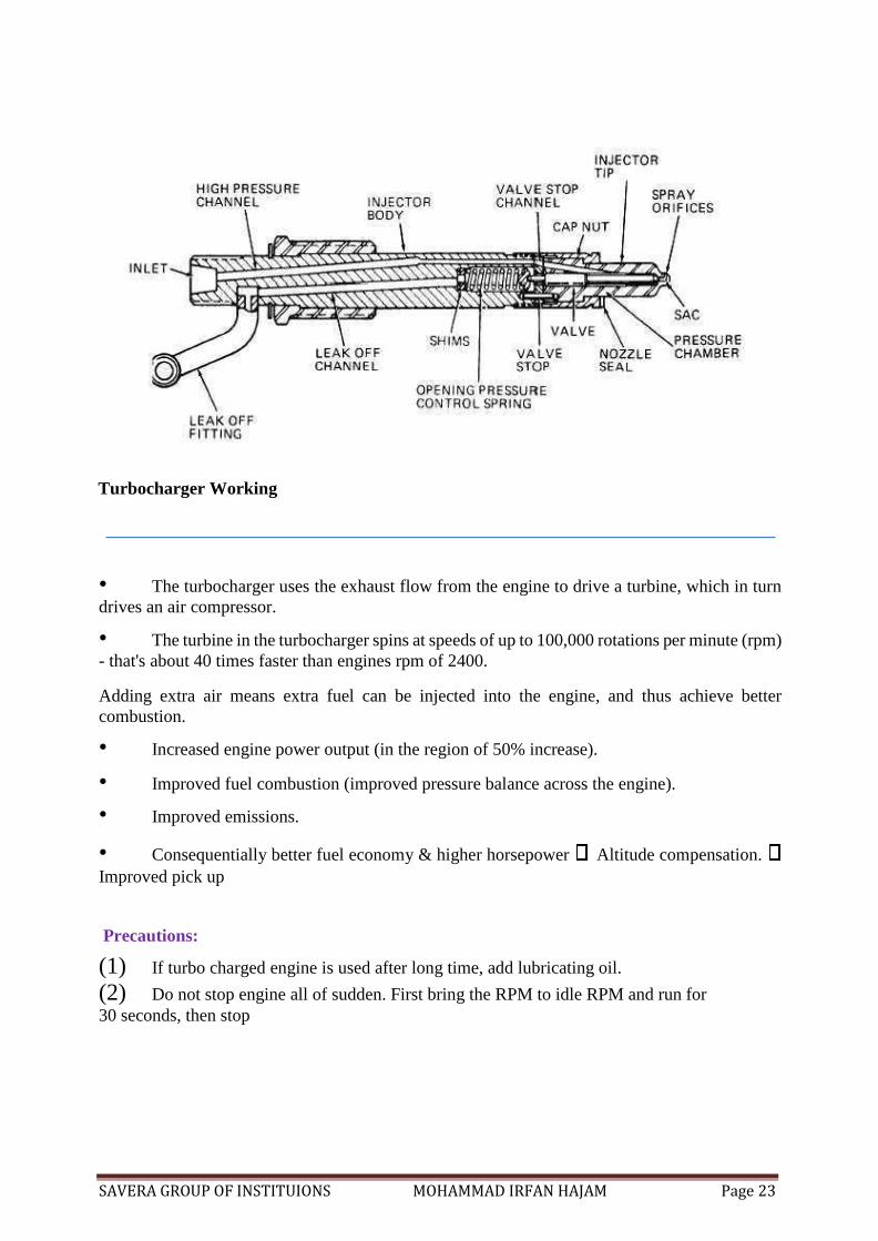
Injectors: - P - types injectors are used in ITL engines, which inject the fuel at around 250
bars of pressure, atomize the fuel & makes homogenous mixture to get maximum thermal
efficiency.
SAVERA GROUP OF INSTITUIONS MOHAMMAD IRFAN HAJAM Page 23
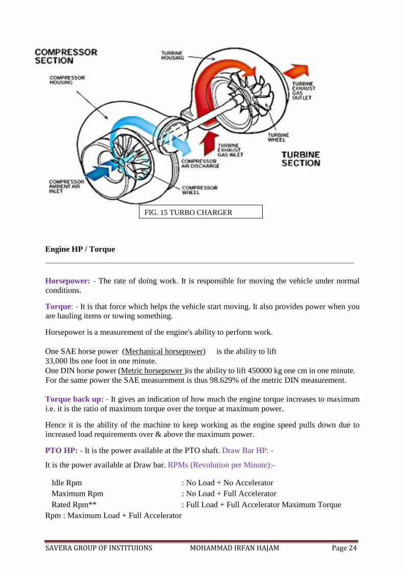
Turbocharger Working
• The turbocharger uses the exhaust flow from the engine to drive a turbine, which in turn
drives an air compressor.
• The turbine in the turbocharger spins at speeds of up to 100,000 rotations per minute (rpm)
- that's about 40 times faster than engines rpm of 2400.
Adding extra air means extra fuel can be injected into the engine, and thus achieve better
combustion.
• Increased engine power output (in the region of 50% increase).
• Improved fuel combustion (improved pressure balance across the engine).
• Improved emissions.
• Consequentially better fuel economy & higher horsepower Altitude compensation. Improved pick up
Precautions:
(1) If turbo charged engine is used after long time, add lubricating oil.
(2) Do not stop engine all of sudden. First bring the RPM to idle RPM and run for
30 seconds, then stop
SAVERA GROUP OF INSTITUIONS MOHAMMAD IRFAN HAJAM Page 24
FIG. 15 TURBO CHARGER
Engine HP / Torque
Horsepower: - The rate of doing work. It is responsible for moving the vehicle under normal
conditions.
Torque: - It is that force which helps the vehicle start moving. It also provides power when you
are hauling items or towing something.
Horsepower is a measurement of the engine's ability to perform work.
One SAE horse power (Mechanical horsepower) is the ability to lift
33,000 lbs one foot in one minute.
One DIN horse power (Metric horsepower )is the ability to lift 450000 kg one cm in one minute.
For the same power the SAE measurement is thus 98.629% of the metric DIN measurement.
Torque back up: - It gives an indication of how much the engine torque increases to maximum
i.e. it is the ratio of maximum torque over the torque at maximum power.
Hence it is the ability of the machine to keep working as the engine speed pulls down due to
increased load requirements over & above the maximum power.
PTO HP: - It is the power available at the PTO shaft. Draw Bar HP: -
It is the power available at Draw bar. RPMs (Revolution per Minute):-
Idle Rpm : No Load + No Accelerator
Maximum Rpm : No Load + Full Accelerator
Rated Rpm** : Full Load + Full Accelerator Maximum Torque
Rpm : Maximum Load + Full Accelerator
SAVERA GROUP OF INSTITUIONS MOHAMMAD IRFAN HAJAM Page 25
Rated RPM - It is the RPM at which the engine produces maximum power
Turning Radius: - The tightest turn a vehicle can make is known as turning radius.
Factors that determines the turning radius of a vehicle
• Wheel base
• Wheel track
• Axle ( Straight or Bend )
• The steering gear box
Turning radius of DI 730 III is 2.37m with brakes & 3.06m without brakes. Bore: -
The internal diameter of liner, usually measured in mm.
Stroke length: - The distance travelled by piston from TDC to BDC
Cubic Capacity: - volume of gasses swept by piston during one stroke.
C.C = π/4 X D² X L
Where,
The value of (π) is 3.14 or 22/7 D is bore size in cm.
And L is length of stroke in cm.
Specific Fuel Consumption: -It is the amount of fuel consumed in grams to produce 1 HP per
hour. It is measured in gm/bhp/hr.
• – If SFC of a Tractor is 179 gm/bhp/hr, it means it consumes 179 grams of oil to produce
1 Hp for 1 hour.
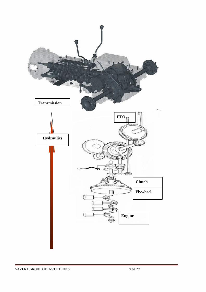
POWER TRANSMISSION SYSTEM OF TRACTOR
Transmission is a speed reducing mechanism, equipped with several gears. It may be called
sequence of gear and shaft through which engine power is transmitted to tractor wheels. The
system consists of various devices that cause forward and backward movement of tractors to
suit different field condition. The complete path of power from engine to wheel is called power
train.
Functions of power transmission system
• To transmit power from engine to rear wheel.
• To make reduce speed available to rear wheel of tractor.
• To alter ratio of wheel speed and engine speed in order to suit field condition.
• To transmit power through right angle drive, because the crank shaft and rear axle are
normally at right angle to each other.
Power transmission system consist of -
• Clutch
SAVERA GROUP OF INSTITUIONS MOHAMMAD IRFAN HAJAM Page 26
• Transmission gear
• Differential
• Final drive
• Rear axle and rear wheel It consists of Clutch, Gearbox & Differential Transmission
serves the following functions: -
• Clutch – Engages or disengages transmission from engine.
• Gear Box - Provides different torque & speed combinations.
- Provides reverse & forward motion.
• Differential - Differentiates power equally between both wheels.
o Provides speed variations between wheels while negotiating turns
SAVERA GROUP OF INSTITUIONS Page 27
Transmission
Clutch
Flywheel
PTO
Hydraulics
Engine
SAVERA GROUP OF INSTITUIONS MOHAMMAD IRFAN HAJAM Page 28
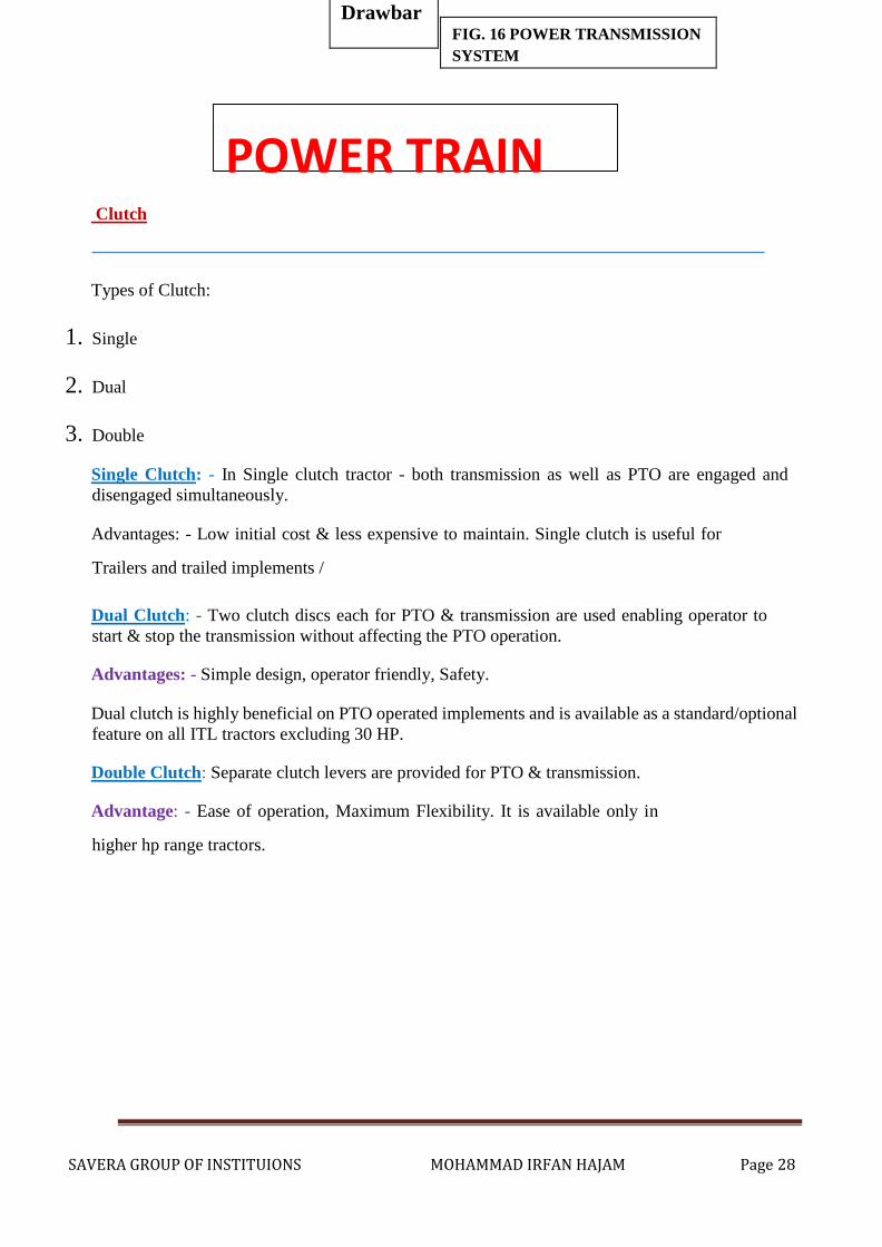
POWER TRAIN
Clutch
Types of Clutch:
1. Single
2. Dual
3. Double
Single Clutch: - In Single clutch tractor - both transmission as well as PTO are engaged and
disengaged simultaneously.
Advantages: - Low initial cost & less expensive to maintain. Single clutch is useful for
Trailers and trailed implements /
Dual Clutch: - Two clutch discs each for PTO & transmission are used enabling operator to
start & stop the transmission without affecting the PTO operation.
Advantages: - Simple design, operator friendly, Safety.
Dual clutch is highly beneficial on PTO operated implements and is available as a standard/optional
feature on all ITL tractors excluding 30 HP.
Double Clutch: Separate clutch levers are provided for PTO & transmission.
Advantage: - Ease of operation, Maximum Flexibility. It is available only in
higher hp range tractors.
FIG. 16 POWER TRANSMISSION
SYSTEM
Drawbar
SAVERA GROUP OF INSTITUIONS MOHAMMAD IRFAN HAJAM Page 29
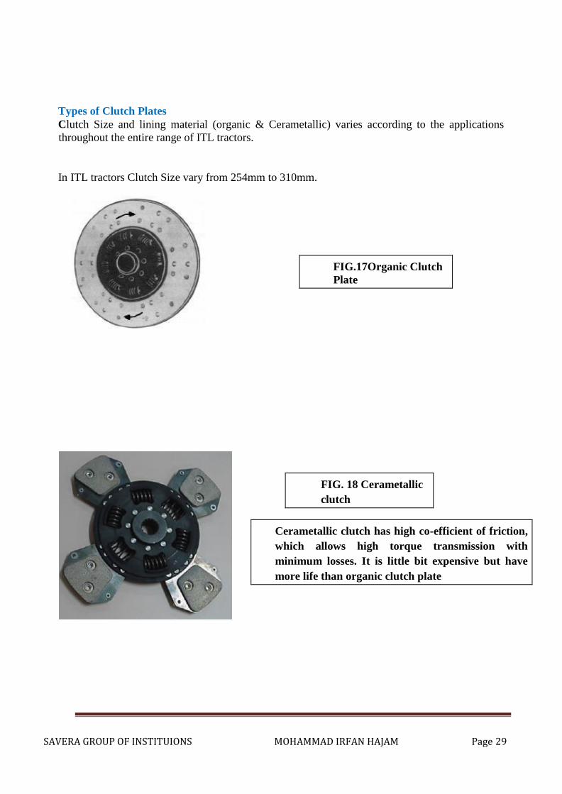
Types of Clutch Plates
Clutch Size and lining material (organic & Cerametallic) varies according to the applications
throughout the entire range of ITL tractors.
In ITL tractors Clutch Size vary from 254mm to 310mm.
FIG.17Organic Clutch
Plate
Cerametallic clutch has high co-efficient of friction,
which allows high torque transmission with
minimum losses. It is little bit expensive but have
more life than organic clutch plate
FIG. 18 Cerametallic
clutch
SAVERA GROUP OF INSTITUIONS MOHAMMAD IRFAN HAJAM Page 30
Gears
A tractor engine runs on at high speed but the rear wheel of tractors requires power at low
speed and high torque. That’s why it become essential to reduce the engine speed and increase torque
available at rear wheel of tractors because
2πnT
Power, =
60×1000
Where, T=torque in Nm,
n=speed in rpm.
Principle of gearing
Any combination of gears by means of which motion is transmitted from one shaft to another shaft
, is called gear train.
Speed of driving gear(Na) No.of teeth on driven gear(Tb)
Speed of driven gear(Nb) =
No.of teeth on driving gear(Ta)
Types of gear box
There are three types of gear boxes available on tractor
• Sliding mesh gear box
• Constant mesh gear box
• Synchromesh gear box
1) Sliding mesh gear box
Most of the indigenous tractors are fitted with is sliding mesh or sliding cum constant mesh
type gear box. The housing of cast iron. It is rigid in construction and serves the purpose of the
tractor frame.
Usually, the main and counter shaft is parallel to clutch shaft, but there are certain cases where
the shaft are transverse. The gear on lay shaft is fixed, where as those on the main shaft slide
to mesh with a suitable gear on the counter shaft.

SAVERA GROUP OF INSTITUIONS MOHAMMAD IRFAN HAJAM Page 31
In this type, lay shaft gears are fixed & movement is provided in main shaft gears during shifting.
1) Constant mesh gear box
The constant mesh transmission has parallel shaft one over the other with gears in constant
mesh. The gears on the main shaft are mounted on bushing and are free to rotate along with
the counter shaft gear without affecting the main shaft when in neutral.
In this type, lay shaft gears are always meshed with main shaft gears, which are free to rotate on main shaft. Hub sleeves are fixed on main shaft & during gear shifting, shifter sleeve
moves toward respective gear for engagement & transfer the same to lay shaft gear.
FIG.19 CONSTANT MESH GEAR
BOX
Advantages:
Ease of gear shifting, reduces noise, wear/breakage & leads to better life.
Standard Feature in Rx & DI Series (above 34 Hp Series Tractors)
Advantages:
Bit noisy operation but Consistent
performance.
SAVERA GROUP OF INSTITUIONS MOHAMMAD IRFAN HAJAM Page 32
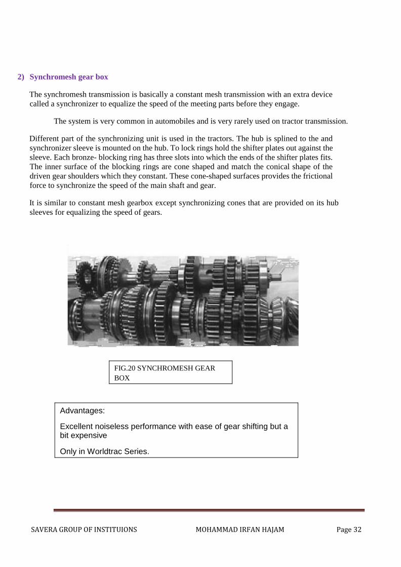
2) Synchromesh gear box
The synchromesh transmission is basically a constant mesh transmission with an extra device
called a synchronizer to equalize the speed of the meeting parts before they engage.
The system is very common in automobiles and is very rarely used on tractor transmission.
Different part of the synchronizing unit is used in the tractors. The hub is splined to the and
synchronizer sleeve is mounted on the hub. To lock rings hold the shifter plates out against the
sleeve. Each bronze- blocking ring has three slots into which the ends of the shifter plates fits.
The inner surface of the blocking rings are cone shaped and match the conical shape of the
driven gear shoulders which they constant. These cone-shaped surfaces provides the frictional
force to synchronize the speed of the main shaft and gear.
It is similar to constant mesh gearbox except synchronizing cones that are provided on its hub
sleeves for equalizing the speed of gears.
FIG.20 SYNCHROMESH GEAR
BOX
Advantages:
Excellent noiseless performance with ease of gear shifting but a bit expensive
Only in Worldtrac Series.
SAVERA GROUP OF INSTITUIONS MOHAMMAD IRFAN HAJAM Page 33
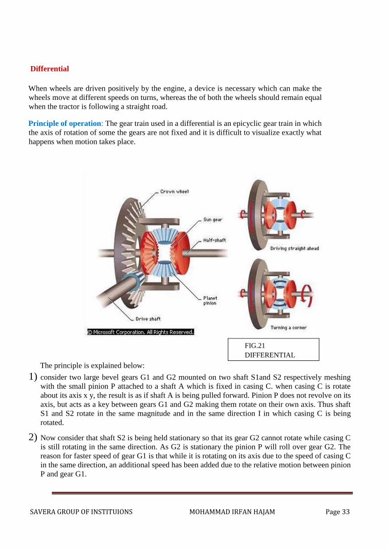
Differential
When wheels are driven positively by the engine, a device is necessary which can make the
wheels move at different speeds on turns, whereas the of both the wheels should remain equal
when the tractor is following a straight road.
Principle of operation: The gear train used in a differential is an epicyclic gear train in which
the axis of rotation of some the gears are not fixed and it is difficult to visualize exactly what
happens when motion takes place.
FIG.21
DIFFERENTIAL
The principle is explained below:
1) consider two large bevel gears G1 and G2 mounted on two shaft S1and S2 respectively meshing
with the small pinion P attached to a shaft A which is fixed in casing C. when casing C is rotate
about its axis x y, the result is as if shaft A is being pulled forward. Pinion P does not revolve on its
axis, but acts as a key between gears G1 and G2 making them rotate on their own axis. Thus shaft
S1 and S2 rotate in the same magnitude and in the same direction I in which casing C is being
rotated.
2) Now consider that shaft S2 is being held stationary so that its gear G2 cannot rotate while casing C
is still rotating in the same direction. As G2 is stationary the pinion P will roll over gear G2. The
reason for faster speed of gear G1 is that while it is rotating on its axis due to the speed of casing C
in the same direction, an additional speed has been added due to the relative motion between pinion
P and gear G1.
SAVERA GROUP OF INSTITUIONS MOHAMMAD IRFAN HAJAM Page 34
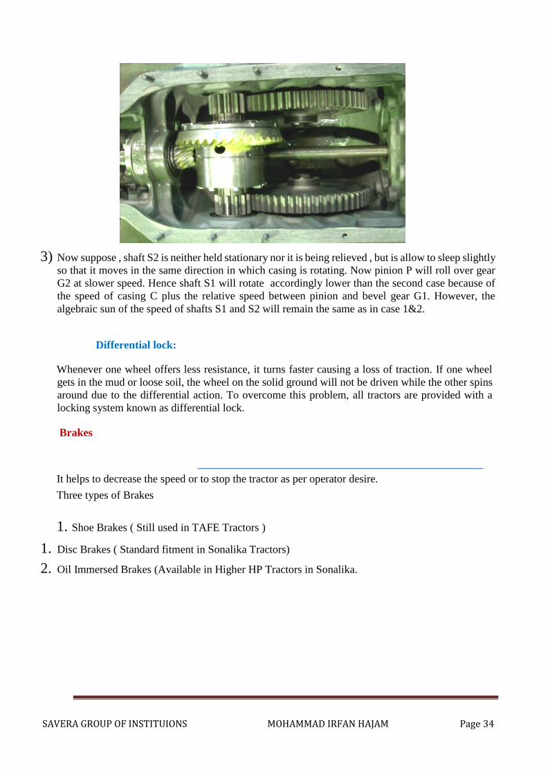
3) Now suppose , shaft S2 is neither held stationary nor it is being relieved , but is allow to sleep slightly
so that it moves in the same direction in which casing is rotating. Now pinion P will roll over gear
G2 at slower speed. Hence shaft S1 will rotate accordingly lower than the second case because of
the speed of casing C plus the relative speed between pinion and bevel gear G1. However, the
algebraic sun of the speed of shafts S1 and S2 will remain the same as in case 1&2.
Differential lock:
Whenever one wheel offers less resistance, it turns faster causing a loss of traction. If one wheel
gets in the mud or loose soil, the wheel on the solid ground will not be driven while the other spins
around due to the differential action. To overcome this problem, all tractors are provided with a
locking system known as differential lock.
Brakes
It helps to decrease the speed or to stop the tractor as per operator desire.
Three types of Brakes
1. Shoe Brakes ( Still used in TAFE Tractors )
1. Disc Brakes ( Standard fitment in Sonalika Tractors)
2. Oil Immersed Brakes (Available in Higher HP Tractors in Sonalika.
SAVERA GROUP OF INSTITUIONS MOHAMMAD IRFAN HAJAM Page 35
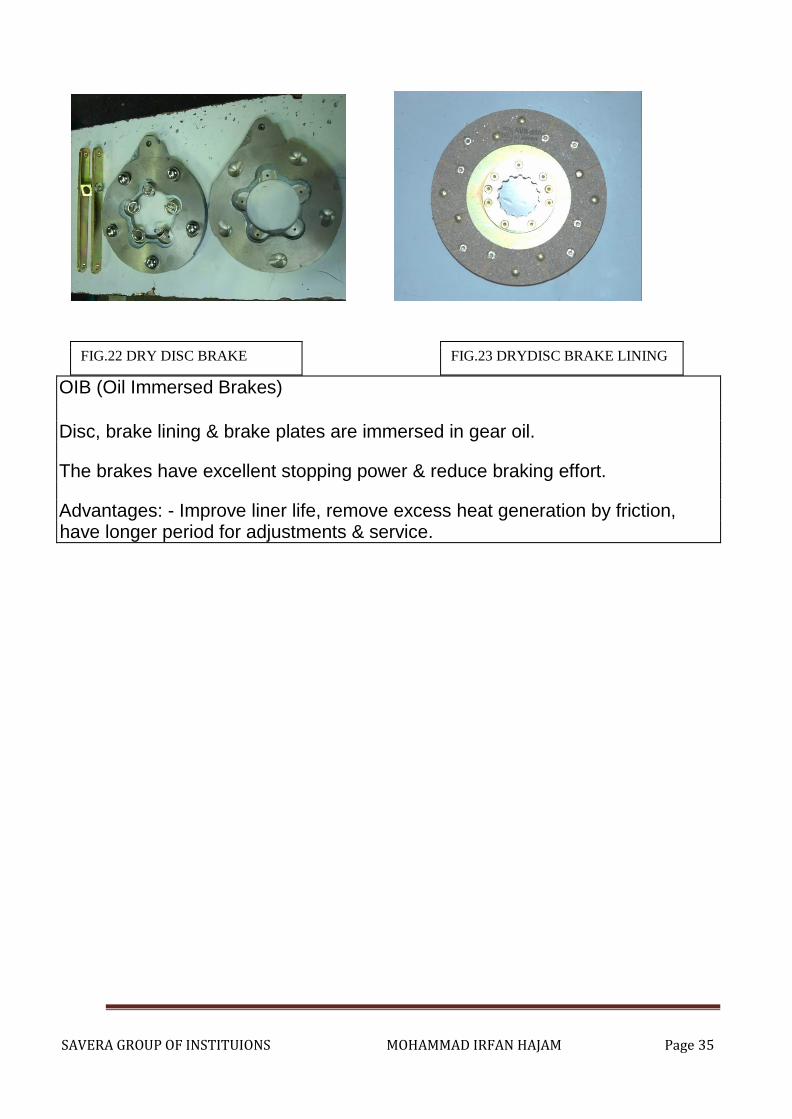
FIG.22 DRY DISC BRAKE FIG.23 DRYDISC BRAKE LINING
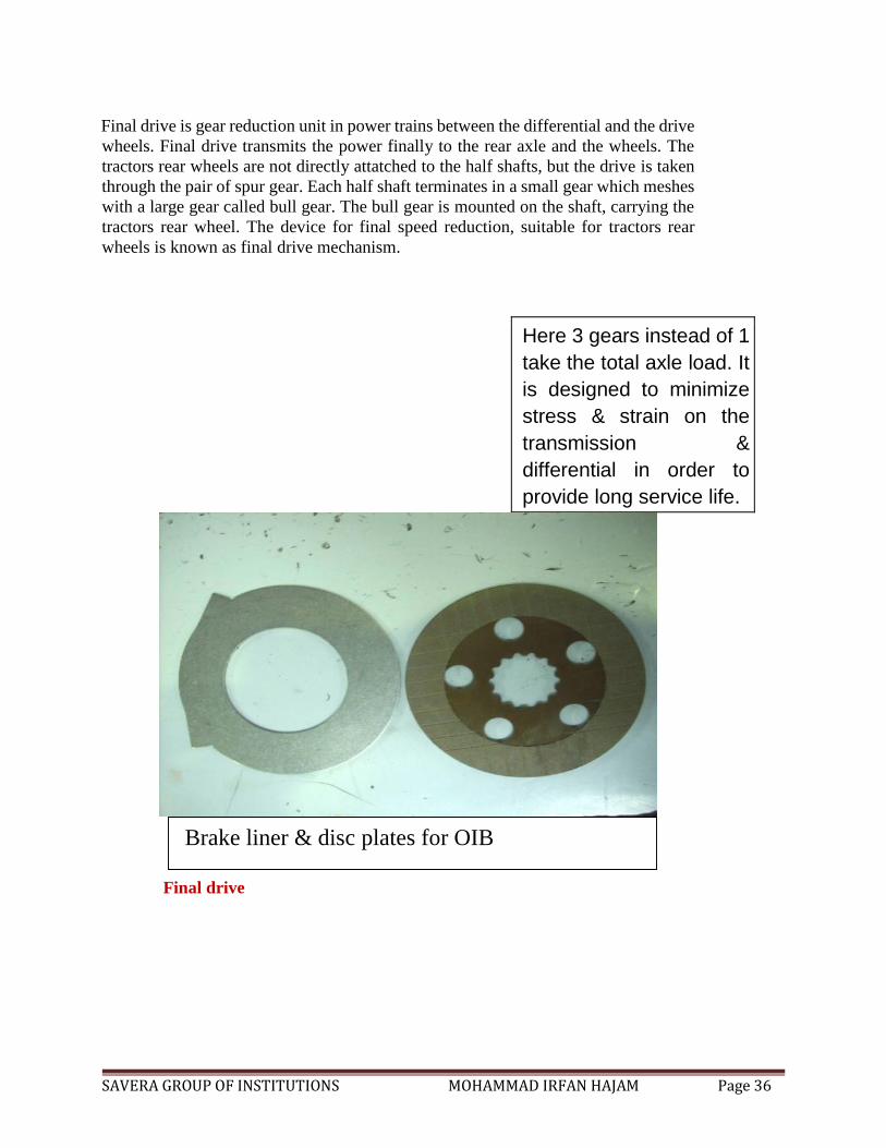
OIB (Oil Immersed Brakes)
Disc, brake lining & brake plates are immersed in gear oil. The brakes have excellent stopping power & reduce braking effort. Advantages: - Improve liner life, remove excess heat generation by friction, have longer period for adjustments & service.
SAVERA GROUP OF INSTITUTIONS MOHAMMAD IRFAN HAJAM Page 36
Final drive is gear reduction unit in power trains between the differential and the drive
wheels. Final drive transmits the power finally to the rear axle and the wheels. The
tractors rear wheels are not directly attatched to the half shafts, but the drive is taken
through the pair of spur gear. Each half shaft terminates in a small gear which meshes
with a large gear called bull gear. The bull gear is mounted on the shaft, carrying the
tractors rear wheel. The device for final speed reduction, suitable for tractors rear
wheels is known as final drive mechanism.
Here 3 gears instead of 1
take the total axle load. It
is designed to minimize
stress & strain on the
transmission &
differential in order to
provide long service life.
Final drive
Brake liner & disc plates for OIB
SAVERA GROUP OF INSTITUTIONS MOHAMMAD IRFAN HAJAM Page 37
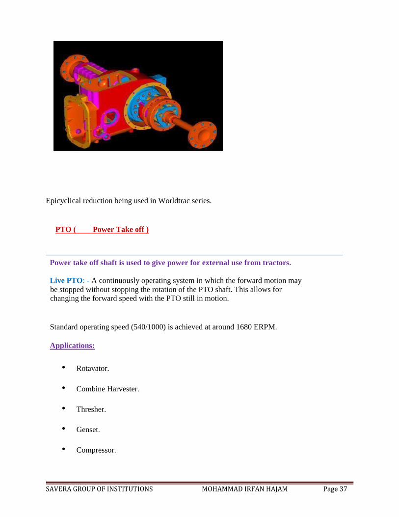
Epicyclical reduction being used in Worldtrac series.
PTO ( Power Take off )
Power take off shaft is used to give power for external use from tractors.
Live PTO: - A continuously operating system in which the forward motion may
be stopped without stopping the rotation of the PTO shaft. This allows for changing the forward speed with the PTO still in motion.
Standard operating speed (540/1000) is achieved at around 1680 ERPM.
Applications:
• Rotavator.
• Combine Harvester.
• Thresher.
• Genset.
• Compressor.
SAVERA GROUP OF INSTITUTIONS MOHAMMAD IRFAN HAJAM Page 38
• Water pump.
• Post Hole Digger.
Ground PTO: - Here the PTO speed is governed by the ground speed of the tractor.
Applications:
• Grass mowers
• Seed Drills
• Baler
• Sprayers
• Planters
PTO standards:
• 6 Spline – 540 RPM
• 21 Spline – 1000RPM
TRACTOR HYDRAULIC SYSTEM
• It is a mechanism in a tractor to raise, hold or lower the mounted or semi-mounted
equipment by hydraulic means.
• A system where fluid is used as a media to transfer power is calledhydraulic system.
• Hydraulic system with reference to tractor is considered to be a unit responsible for
raising, holding & lowering the implement.
• Hydraulic system consists of following components:
• Hydraulic Pump
• Rear Cover Assembly
SAVERA GROUP OF INSTITUTIONS MOHAMMAD IRFAN HAJAM Page 39
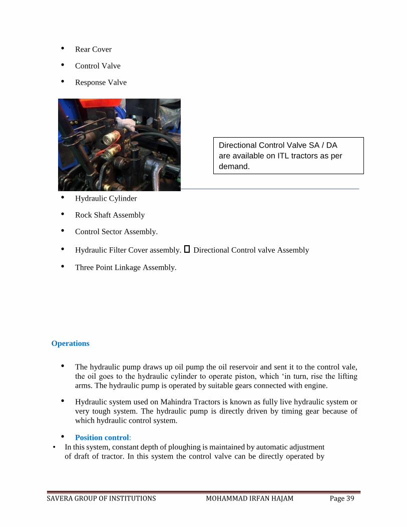
• Rear Cover
• Control Valve
• Response Valve
• Hydraulic Cylinder
• Rock Shaft Assembly
• Control Sector Assembly.
• Hydraulic Filter Cover assembly. Directional Control valve Assembly
• Three Point Linkage Assembly.
Operations
• The hydraulic pump draws up oil pump the oil reservoir and sent it to the control vale,
the oil goes to the hydraulic cylinder to operate piston, which ‘in turn, rise the lifting
arms. The hydraulic pump is operated by suitable gears connected with engine.
• Hydraulic system used on Mahindra Tractors is known as fully live hydraulic system or
very tough system. The hydraulic pump is directly driven by timing gear because of
which hydraulic control system.
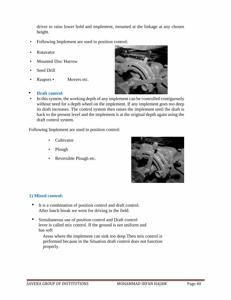
• Position control:
• In this system, constant depth of ploughing is maintained by automatic adjustment
of draft of tractor. In this system the control valve can be directly operated by
Directional Control Valve SA / DA
are available on ITL tractors as per
demand.
SAVERA GROUP OF INSTITUTIONS MOHAMMAD IRFAN HAJAM Page 40
driver to raise lower hold and implement, mounted at the linkage at any chosen
height.
• Following Implement are used in position control:
• Rotavator
• Mounted Disc Harrow
• Seed Drill
• Reapers • Movers etc.
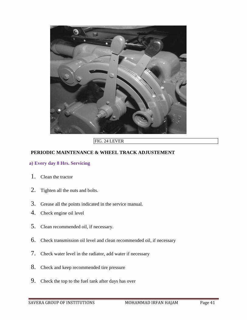
• Draft control:
• In this system, the working depth of any implement can be controlled contiguously
without need for a depth wheel on the implement. If any implement goes too deep
its draft increases. The control system then raises the implement until the draft is
back to the present level and the implement is at the original depth again using the
draft control system.
Following Implement are used in position control:
• Cultivator
• Plough
• Reversible Plough etc.
1) Mixed control:
• It is a combination of position control and draft control.
After lunch break we went for driving in the field.
• Simultaneous use of position control and Draft control
lever is called mix control. If the ground is not uniform and has soft
Areas where the implement can sink too deep Then mix control is
performed because in the Situation draft control does not function properly.
SAVERA GROUP OF INSTITUTIONS MOHAMMAD IRFAN HAJAM Page 41
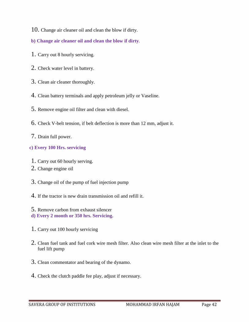
FIG. 24 LEVER
PERIODIC MAINTENANCE & WHEEL TRACK ADJUSTEMENT
a) Every day 8 Hrs. Servicing
1. Clean the tractor
2. Tighten all the nuts and bolts.
3. Grease all the points indicated in the service manual.
4. Check engine oil level
5. Clean recommended oil, if necessary.
6. Check transmission oil level and clean recommended oil, if necessary
7. Check water level in the radiator, add water if necessary
8. Check and keep recommended tire pressure
9. Check the top to the fuel tank after days has over
SAVERA GROUP OF INSTITUTIONS MOHAMMAD IRFAN HAJAM Page 42
10. Change air cleaner oil and clean the blow if dirty.
b) Change air cleaner oil and clean the blow if dirty.
1. Carry out 8 hourly servicing.
2. Check water level in battery.
3. Clean air cleaner thoroughly.
4. Clean battery terminals and apply petroleum jelly or Vaseline.
5. Remove engine oil filter and clean with diesel.
6. Check V-belt tension, if belt deflection is more than 12 mm, adjust it.
7. Drain full power.
c) Every 100 Hrs. servicing
1. Carry out 60 hourly serving.
2. Change engine oil
3. Change oil of the pump of fuel injection pump
4. If the tractor is new drain transmission oil and refill it.
5. Remove carbon from exhaust silencer
d) Every 2 month or 350 hrs. Servicing.
1. Carry out 100 hourly servicing
2. Clean fuel tank and fuel cork wire mesh filter. Also clean wire mesh filter at the inlet to the
fuel lift pump
3. Clean commentator and bearing of the dynamo.
4. Check the clutch paddle fee play, adjust if necessary.
SAVERA GROUP OF INSTITUTIONS MOHAMMAD IRFAN HAJAM Page 43
5. Clean suction tube wire mesh after opening the pump.
6. Change pre-filter insert of the fuel system.
7. Check spray of the injectors.
e) Every one year or 1000 Hrs. Servicing
1. Carry out 350 hourly servicing.
2. Decarbonise cylinder head piston.
3. Check valve sheet.
4. Check water pump bearing.
5. Check dynamo and starter bushes.
6. Wash front wheel bearing with diesel, repack with grease.
7. Tappet clearance, adjust if necessary.
8. Change transmission oil clean drain plough.
9. Reset injectors to correct pressure.
f) Every two yearly servicing
1. Wash all the lubricating oil pipe and passages.
2. Examine main end connecting rod bearing.
3. Recalibrate fuel injection pump.
MAINTENANCE WHEELTRACK ADJUSTMENT
Objectives:
1. While travelling in hilly area.
SAVERA GROUP OF INSTITUTIONS MOHAMMAD IRFAN HAJAM Page 44
2. While inter culturing in field. Track setting
1. Front wheel:
It is adjustable in four inch steps from 48 inch to 80 inch (1219mm to 203mm).
These setting are obtained as follows:
Jack up the tractor and remove to bolts screwing each front axle arm to central and spread axle
arm to obtained desired track width. No change in steering axle connection is necessary. Replace
bolts leaving at least one bolt between two bolts to give additional support to obtained reversed
wheeled discs on 72 tread. Avoid using this wide setting with front end loaded.
2. Rear wheel:
The rear wheel track is adjustable by assembling rings in different positions. At the same time
interchanging wheels may be necessary in order to maintain minimum traction. When changing
setting 52” to 60” to or from setting 68”, 72”, 76”, interchanging wheels confirm that the wheels
are not their correct side by checking that the arrow on the side of the tire pits. In the direction
of forward rotation.
STUDY OF TILLAGE IMPLEMENTS
A) Plough
The main implement for primary tillage is plough it is used for ploughing operation. Ploughing
operation which is as primary tillage operation, preformed to cut, break and invert the soil
partially or completely. Ploughing essentially means opening the upper crust of the soil, breaking
the clods and making the soil suitable for sowing seeds. The purpose of Ploughing can be
summarized as follows.
1. To obtain a deep seed bed of good texture
2. To increase the water holding capacity of the soil
3. To improve soil aeration
4. To destroy weeds and grasses.
5. To destroy insects and pests
6. To prevent soil erosion
SAVERA GROUP OF INSTITUTIONS MOHAMMAD IRFAN HAJAM Page 45
7. To add fertility to the soil by covering it with
TYPES OF PLOUGH
Different types Of Plough are used at different places. They may be classified as
1. Indigenous plough
2. Mould board plough
3. Disc plough Chisel plough
4. Sub soiler
5. Rotary plough
6. Chisel plough
Mould board plough
A mould board plough is very common implement used for primary tillage operations. This
plough perform several function
Functions
1. Cutting the furrow slice
2. Lifting the soil
3. Turing the furrow slice and
4. Pulverizing the soil
Components
M.B, plough consists of
a) Share b) M.B plough c) Land side d) Land side e) Frog f) Tail piece
Types of share -
Share is of different type such as
1. Slip share
SAVERA GROUP OF INSTITUTIONS MOHAMMAD IRFAN HAJAM Page 46
2. Slip nose share
3. Shin share
4. Bar point share
Mouldboard: It is the curved part which lifts and turn the furrow slice
Land side: It is the flat plate which is bear against and transmit the rear side lateral thrust of the
plough bottom to the furrow wall.
Frog: it is the part to which other components of the plough bottom are attached.
Tail piece: It is adjustable extension which can be fastened to the rear of a mould board to help
in trying.
Plough Accessories
There are few accessories necessary for plough such as
1. Jointer 2. Counter 3. Gauge wheel 4. Land wheel and 5. Furrow wheel
Adjustment of mouldboard Plough
1. Vertical suction: It is maximum clearance under the land side and the horizontal surface
when the plough is resting on horizontal surface in the working position. It helps the plough
penetrate in to soil to a proper depth.
2. Horizontal suction: It is the maximum clearance between the land side and a horizontal
plane touching point of share at its gunnels side and heel of land side. It helps the plough to cut
the proper width of furrow slice. It is also known as side clearance.
3. Vertical clevis: It is a vertical plate with a number of holes, at the end of the beam to
control the depth of operation.
4. Horizontal clevis: it is a device to make lateral adjustment of this plough related to line of
pull.
B) HARROW
A harrow is an implement that cuts the soil to a shallow depth for smoothening and
pulverizing, the soil as to cut weds and to mix materials with soil. It is an Implement used to
break the clods after Ploughing, to collect trash from the ploughed land and to level the seed bed
HARROWING
It is a secondary tillage operation which pulverizes, smoothens and packs

SAVERA GROUP OF INSTITUTIONS MOHAMMAD IRFAN HAJAM Page 47
the soil in seeded preparation and or control weeds.
1) Disk harrow 2) Spraying tooth harrow 3) Pike tooth harrow 4) Blade harrow 5) Guntaka 6)
Triangular harrow 7) Bodela 8) Zig-zag harrow 9) Bindha 10) Patella harrow 11) Acme harrow
12) Reciprocating power harrow.
Disk harrow
It is harrow which perform harrowing operation by means
of a set
Rotating steel disc. Each set being mounted on a common shaft. Dish harrow are of two types
depending upon the sources of power.
A) Tractor drawn
B) Animal drawn
A) Tractor drawn disc harrow
Depending upon disc arrangement disc harrow are divided into two classes, a)
Single acting disc harrow
b) Double action disc harrow
Component of disc harrow:
A disc harrow mainly consist of 1)Disc 2)gang frame 3)Beam 4)gang angle mechanism
5)scrapper 6)spacer axle 7)middle tyne 8)baring 9)spacer 10)clevis
Disc harrow is used for breaking clods while preparing seed beds. The disc mainly consist of
1)Disc 2)Gang frame 3)Beam 4)Gang angle mechanism 5)Scrapper 6)Baring 7)Spacer 8)Clevis
B) Cultivator:
It is an implement for Inter Cultivation with laterally adjustable tines or disc to work between
crop rows. This can be used for seed bed preparation and for sowing with seeding attachment.
The lines may have provision for vertical adjustments also. The cultivator can be
i) Disc Cultivator ii) Rotary Cultivator iii) Tine Cultivator
i) Disc Cultivator:-It is a cultivator fitted with discs ii)
Rotary Cultivator:-It is a cultivator with lines.
SAVERA GROUP OF INSTITUTIONS MOHAMMAD IRFAN HAJAM Page 48
iii) Tine Cultivator: - It is a cultivator fitted with lines having shovels. The cultivator shovels.
The cultivator stirs the soil, and breaks the clods.
The following are a few important functions performed by a cultivator.
I. Intercultural the field.
II. Destroy the weeds fields.
III. Aerate the soil for proper growth of crops.
Classification of Cultivator:-
i) Tractor drawn ii) Animal drawn
i) Tractor drawn cultivator
It may be i) Trailed ii) Mounted
Trailed Type Cultivator:-
It is consists of a main frame which carries a number of cross members of which lines are
fitted. On the front side of the cultivator, there is hitch arrangement for hitching purpose.
Mounted Cultivator
Tractors fitted which hydraulic lift an operate the mounted type cultivators. A rectangular
frame of angle iron is mounted on three point hydraulic linkage of the tractor. The cross members
carry the lines in two staggered lines.
Usually tractor drawn cultivators are of two types
i) Cultivator with spring loaded tines.
ii) Cultivator with rigid tines.
iii) Cultivator with spring loaded tines:-
A tine hinged to the frame and loaded with a spring so that it swings back when an
obstacle is encrusted is called spring loaded tine.
ii) Cultivator with rigid tines:-
Rigid tine of the cultivators are these lines which do not deflate during the work in the
field.
SAVERA GROUP OF INSTITUTIONS MOHAMMAD IRFAN HAJAM Page 49
References
1) Farm Tractor Maintenance & Repair by- S. C. Jain & C. R. Rai
2) Elements of Agricultural Engineering by- Dr. Jagdishwar Sahay
3) www.google.com for much of the information and linked sites.
4) www.sonalika.com for the company profile.
5) I.T.L. for giving handouts to write the report.
6) www.wikipedia.com for the photos and other useful information.