
Investigations of the Geometrical Accuracy of Handheld 3D ... · PFG 2016 / 5 – 6 , 271– 283...
13
PFG 2016 / 5 – 6, 271 – 283 Article Stuttgart, December 2016 © 2016 E. Schweizerbart'sche Verlagsbuchhandlung, Stuttgart, Germany www.schweizerbart.de DOI: 10.1127/pfg/2016/0305 1432-8364/16/0305 $ 3.25 a few metres. Due to the current technological variety within the area of 3D scanning, it is a challenge to select a suitable scanning system for a specific application. Geometric accura- cy investigations of terrestrial laser scanning systems were already published by KERSTEN et al. (2009), while an accuracy analysis of a handheld mobile laser scanning system for cultural heritage documentation was recently published by CHAN et al. (2016). 1 Introduction In recent years the market of optical 3D sen- sors has been significantly expanded in the lower (500 Euro to 4,900 Euro), middle (5,000 Euro to 20,000 Euro) and high-end (more than 20,000 Euro) price segment through the devel- opment of handheld 3D scanners. The typi- cal application fields of these 3D scanners are mostly limited to close range, i.e. for measur- ing tasks with distances under one metre up to Investigations of the Geometrical Accuracy of Handheld 3D Scanning Systems T HOMAS P. KERSTEN, Hamburg, HEINZ-JÜRGEN PRZYBILLA, Bochum & MAREN LINDSTAEDT , Hamburg Keywords: 3D comparison, point cloud, structured light, VDI/VDE 2634 Summary: An increasing number of handheld scanning systems by different manufacturers is be- coming available on the market. However, their geometrical performance is little-known to many users. Therefore, the Laboratory for Photogramme- try & Laser Scanning of the HafenCity University Hamburg has carried out geometrical accuracy tests with the following systems in co-operation with the Bochum University of Applied Sciences (Laboratory for Photogrammetry): DOTProduct DPI-7/DPI-8, Artec Spider, Mantis Vision F5 SR, and Creaform HandySCAN 700. In the framework of these comparative investigations geometrically stable reference bodies were used. The appropriate reference data was acquired by measurements with two structured light projection systems (AICON smartSCAN and GOM ATOS I 2M). The compre- hensive test results of the different test scenarios are presented and critically discussed in this contri- bution. Zusammenfassung: Untersuchungen zur geomet- rischen Genauigkeit von handgeführten 3D-Scan- ningsystemen. Handgeführte Scannersysteme ver- schiedener Hersteller sind in zunehmendem Maße am Markt verfügbar, jedoch ist über ihre geometri- sche Leistungsfähigkeit bei vielen Anwendern we- nig bekannt. Daher hat das Labor für Photogram- metrie & Laserscanning der HafenCity Universität Hamburg in Zusammenarbeit mit der Hochschule Bochum (Labor für Photogrammetrie) geometri- sche Genauigkeitsuntersuchungen mit folgenden Systemen durchgeführt: DOTProduct DPI-7/DPI- 8, Artec Spider, Mantis Vision F5 SR und Creaform HandySCAN 700. Im Rahmen dieser vergleichen- den Untersuchungen wurden geometrisch stabile Referenzkörper eingesetzt. Die zugehörigen Refe- renzdaten wurden durch Messung mit zwei Strei- fenprojektionssystemen (AICON smartSCAN und GOM ATOS I 2M) erfasst. Die umfassenden Un- tersuchungsergebnisse der verschiedenen Testsze- narien werden in diesem Beitrag vorgestellt und kritisch diskutiert.
Transcript of Investigations of the Geometrical Accuracy of Handheld 3D ... · PFG 2016 / 5 – 6 , 271– 283...

PFG 2016 / 5 – 6, 271 – 283 ArticleStuttgart, December 2016
© 2016 E. Schweizerbart'sche Verlagsbuchhandlung, Stuttgart, Germany www.schweizerbart.deDOI: 10.1127/pfg/2016/0305 1432-8364/16/0305 $ 3.25
a few metres. Due to the current technological variety within the area of 3D scanning, it is a challenge to select a suitable scanning system for a specific application. Geometric accura-cy investigations of terrestrial laser scanning systems were already published by Kersten et al. (2009), while an accuracy analysis of a handheld mobile laser scanning system for cultural heritage documentation was recently published by cHan et al. (2016).
1 Introduction
In recent years the market of optical 3D sen-sors has been significantly expanded in the lower (500 Euro to 4,900 Euro), middle (5,000 Euro to 20,000 Euro) and high-end (more than 20,000 Euro) price segment through the devel-opment of handheld 3D scanners. The typi-cal application fields of these 3D scanners are mostly limited to close range, i.e. for measur-ing tasks with distances under one metre up to
Investigations of the Geometrical Accuracy of Handheld 3D Scanning Systems
Thomas P. KersTen, Hamburg, heinz-Jürgen Przybilla, Bochum & maren lindsTaedT, Hamburg
Keywords: 3D comparison, point cloud, structured light, VDI/VDE 2634
Summary: An increasing number of handheld scanning systems by different manufacturers is be-coming available on the market. However, their geometrical performance is little-known to many users. Therefore, the Laboratory for Photogramme-try & Laser Scanning of the HafenCity University Hamburg has carried out geometrical accuracy tests with the following systems in co-operation with the Bochum University of Applied Sciences (Laboratory for Photogrammetry): DOTProduct DPI-7/DPI-8, Artec Spider, Mantis Vision F5 SR, and Creaform HandySCAN 700. In the framework of these comparative investigations geometrically stable reference bodies were used. The appropriate reference data was acquired by measurements with two structured light projection systems (AICON smartSCAN and GOM ATOS I 2M). The compre-hensive test results of the different test scenarios are presented and critically discussed in this contri-bution.
Zusammenfassung: Untersuchungen zur geomet-rischen Genauigkeit von handgeführten 3D-Scan-ningsystemen. Handgeführte Scannersysteme ver-schiedener Hersteller sind in zunehmendem Maße am Markt verfügbar, jedoch ist über ihre geometri-sche Leistungsfähigkeit bei vielen Anwendern we-nig bekannt. Daher hat das Labor für Photogram-metrie & Laserscanning der HafenCity Universität Hamburg in Zusammenarbeit mit der Hochschule Bochum (Labor für Photogrammetrie) geometri-sche Genauigkeitsuntersuchungen mit folgenden Systemen durchgeführt: DOTProduct DPI-7/DPI-8, Artec Spider, Mantis Vision F5 SR und Creaform HandySCAN 700. Im Rahmen dieser vergleichen-den Untersuchungen wurden geometrisch stabile Referenzkörper eingesetzt. Die zugehörigen Refe-renzdaten wurden durch Messung mit zwei Strei-fenprojektionssystemen (AICON smartSCAN und GOM ATOS I 2M) erfasst. Die umfassenden Un-tersuchungsergebnisse der verschiedenen Testsze-narien werden in diesem Beitrag vorgestellt und kritisch diskutiert.

272 Photogrammetrie • Fernerkundung • Geoinformation 5 – 6/2016
Handheld 3D scanners are an optimal sup-plement to terrestrial laser scanning. However, due to their favourable price and their simple handling these handheld scanners also poten-tially represent significant competition to the expensive and precise structured light projec-tion systems (also known as fringe projection). Therefore, the question arises, how accurate these 3D scanners are compared to classical structured light systems, e.g. from the man-ufacturers GOM (2016), steinbicHler (Zeiss 2016) or AICON (AICON3D 2016), and what metric quality the user can expect for the ac-quired 3D data as a price-to-performance ra-tio. In this area, some results are already avail-able in the literature, e.g. for systems from the gaming industry as well as so-called low-cost systems (structured light system David SLS-1 and Kinect v1/ReconstructMe) for the 3D reconstruction of small objects (HieronyMus et al. 2011, WuJanz et al. 2011, KHosHelHaM 2011, boeHM 2014, Kersten et al. 2016a). As expected, these investigations demonstrate that the stability and the metric quality of these systems cannot at present compete with high-end systems.
In the following contribution, geometrical accuracy tests using different handheld 3D scanners (middle price class) will be present-ed as a continuation of the first tests includ-ing low-cost systems such as Structure Sen-sor, Kinect v1 and v2, and Google s Project Tango (Kersten et al. 2016b). For these inves-tigations reference datasets that were derived from measurements with high-end structured light systems (AICON smartSCAN and GOM ATOS I 2M) for different stable bodies were used.
2 Reference Bodies
For the benchmarking test the following refer-ence objects were used (Fig. 1): a gypsum bust of Einstein (height of 160 mm), a wheel hub from cast irons with the dimensions 232 × 120 × 232 mm3 and four so-called “Testys” (height of 380 mm) from the Institute for Computer Science of the Humboldt University in Berlin (reulKe & MisgaisKi 2012). Further examina-tions took place using the following geomet-rically-stable reference bodies from the Bo-chum University of Applied Sciences (HSBO): a cross-shaped body with steel spheres (max. distance 450 mm of five spheres with a diam-eter of 65 mm) and a planar granite slab (size 300 × 300 mm2).
3 Tested Handheld 3D Scanning Systems
The following handheld 3D scanning systems (Fig. 2), with selected technical data summa-rized in Tab. 1, were available for the tests: two DotProduct DPI-7 (State Office of Crim-inal Investigations Hamburg (LKA), and Dr. Hesse and Partner Engineers, dhp:i), Dot-Product DPI-8 (AllTerra Deutschland GmbH, Schenefeld), Artec Spider (LKA, Hamburg), Mantis Vision F5 Short Range (MexCon-sult, Bredstedt), Creaform HandySCAN 700 (Hanack und Partner, Hamburg).
Fig. 1: Reference bodies for the investigations of the handheld scanning systems – from left. Ein-stein bust, wheel hub, Testy, cross-shaped body HSBO (Bochum) with spheres and granite slab.

Thomas P. Kersten et al., Handheld 3D Scanning Systems 273
3.1 DotProduct DPI-7/DPI-8
A substantial component of the hardware of the DPI-7 (dotProduct 2016) and DPI-8 scan-ner (DotProduct, USA) is a PrimeSense sen-sor (Carmine 1.08/Carmine 1.09), as it is also mounted in the Kinect v1 (NIR projector as well as NIR and RGB cameras). After a cold boot the system needs approximately 20 min-utes preheating time. The control of the sensor is carried out by a connected Android tablet us-ing the software Phi.3D. For the registration of the point clouds the sensor data of the internal accelerometers and gyroscopes of the tablet are used. If sufficient overlap is available for the scans (control via visual colour information at the tablet), an ICP algorithm (besl & McKay 1992) performs a pre-registration of scans. Af-ter scanning, the registration will be optimized by also eliminating incorrect points, e.g. mixed pixels. The measuring range of the DPI-7 scan-ner is between 0.6 m and 3.3 m (0.6 m and 5.0 m for DPI-8 according Trimble’s specifica-
tion), whereby a short range version with up to 1.2 m range (system of dhp:i) and a long range version with up to 3.3 m (systems of the LKA) are available. The instrument has the dimen-sions of 20 × 24 × 6 cm3. Investigations of the DPI-7 are presented by JaHraus et al. (2015), applications by aHern & sPring (2015).
3.2 Artec Spider
Artec Spider (artec3D 2016, Luxembourg) is a handheld 3D scanner, which was devel-oped particularly for CAD users, to scan small items with complex surface structure, sharp edges and thin ribs with 7.5 photos or with 1 million points per second. The system needs a preheating time of approximately 30 minutes and works with a linear field of view between 90 × 70 mm2 and 180 × 140 mm2. The meas-uring range is between 0.17 m – 0.35 m. The Artec Spider uses structured light technolo-
Fig. 2: Examined handheld scanner systems (from left): DPI-7, DPI-8, Artec Spider, Mantis Vision F5 SR, and Creaform HandySCAN 700.
Tab. 1: Selected technical data of the examined 3D scanners (manufacturer’s data).
System Measuring procedure(SL = Structured Light)
Range(m)
Precision(mm)
Weight (kg)
Cost(Euro)
DPI-7 (dhp:i) SL – speckle pattern 0.60 – 1.20 2 (@ 1m) < 1.00 5,000DPI-7 (LKA) SL – speckle pattern 0.60 – 3.30 2 (@ 1m) < 1.00 5,000
DPI-8 SL – speckle pattern 0.60 – 5.00 2 (@ 1m) < 1.00 4,700Artec Spider SL – speckle pattern 0.17 – 0.35 0.05 < 1.00 15,700Mantis F5 SR SL – speckle pattern 0.30 – 0.80 0.05 (@
50cm)0.60 15,000
HandySCAN 700
Stereo-Photogrammetry 0.10 – 4.00 up to 0.03 0.85 49,000
ATOS I 2M SL – Gray code 0.16 – 1.28 0.02 3.50 50,000smartSCAN SL – Gray code 0.03 – 1.50 0.009 (plane) 4.00 80,000

274 Photogrammetrie • Fernerkundung • Geoinformation 5 – 6/2016
gy (speckle pattern) with blue LED as a light source and a colour camera with 1.3 megapix-els (24-bit radiometry) for the texture map-ping of the objects. For the generation of 3D models the software Artec studio can be used in combination with the measuring system. Sample applications of this system have been published by adaMs et al. (2015), FriedMan et al. (2015) as well as inzerillo et al. (2015).
3.3 Mantis Vision F5 Short Range
The Mantis Vision F5 (Israel) is a struc-tured-light handheld scanner with a measur-ing range of 0.5 m – 4.5 m (MVC F5) respec-tively 0.3 m – 0.8 m (MV F5 Short Range) (OR3D 2016). The sensor hardware consists of two modules: a video camera and a projector, which is integrated in a grab handle. The pro-jector emits infrared light on the object (pro-prietary pattern), which is captured as coded light by a video camera. The triangulation al-gorithm calculates a point cloud with 500,000 points/sec. The point density in XY is 1.6 mm @ 0.5 m distance for each image. The depth of field of the sensor-system is about 0.3 m – 0.8 m. Because of the low sensitivity to the ambient light, the system is usable both in darkness and in daylight. Wrona (2014) and zHang et al. (2015) describe diverse applica-tions of the scanner.
3.4 Creaform HandySCAN 700
The HandySCAN 700 (creaForM 2016) has been introduced as the newest generation of handheld 3D scanning systems from Creaform in May 2014 as “portable 3D measuring solu-tions and 3D engineering services” (aMeteK 2016). Creaform was founded in Lévis, Québec, Canada in May 2002 and is now a part of AM-ETEK Ultra Precision Technologies. The port-able 3D scanner is equipped with power sup-ply, USB 3.0 cable, calibration board, USB stick, positioning targets and a notebook com-puter with the software VXelements. The re-solution of the sensor is 0.050 mm, while the scanning area is 275 mm × 250 mm with a depth of field of 250 mm. Two principal cam-eras, integrated at the front of the sensor on top
of each other, acquire 60 images per second. Using seven laser crosses (plus one extra line for difficult accessible areas) as a light source, the system is able to provide 480,000 measure-ments per second to generate the point cloud for 3D meshing. The sensor position is deter-mined in real-time by spatial resection using retro-reflective targets in object space. ouiMet et al. (2015) present the use of the former sys-tem HandySCAN 3D for the documentation of masonry sculptural elements of the Canadian Parliament Buildings. starosta (2016) investi-gated the operational capability of the 3D scan-ner HandySCAN 700.
3.5 Reference systems – ATOS I 2M and AICON smartSCAN 3D
The GOM (Company for Optical Measuring Technology) ATOS (Advanced Topometric Sensor) I 2M, Braunschweig, Germany, is a structured light projection system (Gray code/phase shift) consisting of two CCD cameras having 1624 × 1236 pixels each and a struc-tured light projector. Depending on the lenses used the field of view varies between 500 × 400 mm2 and 250 × 200 mm2. The ATOS I 2M had been employed as a measuring and refer-ence system in different applications (Ker-sten et al. 2012, rau & yeH 2012, Kersten & lindstaedt 2012, Kersten et al. 2016a).
The smartSCAN 3D from AICON 3D Sys-tems GmbH, Braunschweig, Germany, is a structured light projection system (white light scanner), which operates with the combined gray-code/phase-shift technology. The cam-eras (in this case delivering 5 Megapixel) re-cord the structured-light pattern (light source: white LED, alternatively green, blue or red) under a predefined triangulation angle, with a measuring sequence of one second. The scan-ner works in a measuring range from 30 mm to 1500 mm. Examples of use are presented by slizeWsKi et al. (2010) and batHoW & breucK-Mann (2011).
4 Data Acquisition
The measurements took place on the 5th and 6th of January and 6th of July 2016 in the Geomat-
Thomas P. Kersten et al., Handheld 3D Scanning Systems 275
ics lab at the HafenCity University Hamburg. At various stations data of the reference bod-ies had been derived from handheld 3D scan-ners, cameras and the two reference systems. For the wheel hub and the cross-shaped HSBO test body a coating spray was used to convert the shiny surface into a matt and bright sur-face.
For data acquisition all handheld scanners have to be moved manually, in a slow and uniform movement, around the whole object in a distance between 20 cm and 50 cm. The collected data is transferred to the connected tablet (DPI-7/DPI-8, Mantis F5) or computer (Artec Spider, HandySCAN 700) in real time and displayed in the software. Normally the instruments are used in one go, after hav-ing passed through the usual warm-up phase. No turning off occurred during the measure-ments of a specified reference body, although some of the sensors, e.g. DotProduct DPI, take a short break (less than 1 minute for an ad-ditional warm-up of the camera) when begin-ning a new imaging session. Fast or abrupt movements should be avoided because they will lead to a loss of the continuous automatic registration. Should such an interruption oc-cur, it can be handled in the software in dif-ferent ways. For instance, the DPI-7 and the DPI-8 have to be moved again over a part of the object that has already been captured for re-orientation. The Mantis Vision F5 control unit only shows the current video image and not the captured data, so a possible loss of sig-nal can only be repaired by registration of seg-ments in post processing. The experience of the operator influences the speed and quality of data collection significantly. The manual movements of the sensor have to be coordi-nated with the live-view on the display. The acquisition time is a few minutes for all scan-ners, depending on the object complexity; two of the systems need a preheating time first (Artec Spider and DPI-7/DPI-8).
For the measurements with the structured light projection systems ATOS I 2M and smart-SCAN the objects were placed on turntables. The systems were calibrated before the re-cording started. The data collection is done in a number of single scans, which are registered to each other by using small targets stuck onto the object (ATOS) or matching aids (small, ex-
plicit geometrically structured objects), which are placed in object space (smartSCAN). For the ATOS system the number of scans per ob-ject lay between 24 and 120 with the registra-tion accuracy differing between 0.023 mm and 0.041 mm. Generally, the number of scans differs, depending on the size, shape and over-all complexity of the object. To measure the HSBO cross-shaped body, 70 scans had to be acquired using the smartSCAN, while the ac-quisition of the granite slab could be complet-ed with only 10 scans.
5 Evaluation and Results
To evaluate the data from the diverse measure-ment systems multiple formats had to be pro-cessed. Some systems delivered point clouds (DPI-7/DPI-8), some others already generated 3D models on the fly by triangulating mesh-es using the system software (Mantis F5, Ar-tec Spider, HandySCAN 700, ATOS, smart-SCAN).
Three reference bodies (Testy, wheel hub and a bust of Einstein) were measured in detail and at high precision with the fringe projec-tion systems and afterwards the meshing was carried out using Geomagic Studio 2012 (geo-Magic 2016). The ATOS system generated the reference datasets for Testy 1, 2 and 3, while Testy 4, the wheel hub and the bust of Einstein were measured with the smartSCAN.
The guideline VDI/VDE 2634, part 2 and 3, is an accredited standard for acceptance tests (verifying the specified accuracy) and rever-ification (to ensure long-term compliance) of optical measurement systems based on area scanning (VDI/VDE 2002, 2006). Using the framework of well-defined test scenarios, suitable test objects (artefacts) are employed to determine quality parameters. Following the guidelines, tests were executed using the cross-shaped body HSBO with spheres and the granite slab. The derivable quality param-eters are:
• Probing error PS (size): This quality pa-rameter arises from the difference be-tween the measured diameter and the di-ameter of the calibrated sphere.
• Probing error PF (shape): This quality parameter is the range of the radial dis-

276 Photogrammetrie • Fernerkundung • Geoinformation 5 – 6/2016
tance between the measured points and a best-fit sphere. The best-fit sphere is de-termined according to the least-squares method with free radius.
• The sphere-spacing error SD is deter-mined from the difference between the measured and calibrated values of the distance between the centres of two spheres. The measured distance is de-rived from the measured values obtained from multiple area-based probings. The limit, SD, for the permissible three-di-mensional sphere-spacing error is the quality parameter sphere-spacing error. It is determined as a length-independent quantity and shall be observed within the entire measuring volume specified.
• The quality parameter flatness measure-ment error, RE, is the range of the signed distances of the measurement point from the best-fit plane calculated according to the least-squares method.
To evaluate the datasets and calculate the quality parameters Geomagic Studio was used.
5.1 Cross-shaped Reference Body HSBO with Spheres
Fig. 3 shows the probing errors (PS and PF) determined for the HSBO reference body. The characteristic curves of the reference system smartSCAN refer to a comparative measure-
ment with a laser tracker API T3 (interfero-metric measurement accuracy: > ±15 μm or 1.5 ppm), while the other graphs are refer-enced to the smartSCAN system. Related to the probing error PS (Fig. 3 left) it is remark-able that some sensors (DPI-7, DPI-8, Mantis F5) point out systematic deviations: measure-ments are too large or too small. Therefore, it can be assumed that the systems have scale problems from the sensor calibration. Com-pared to the reference system the probing er-ror PS of these systems is larger by a factor of about 5 – 35. The best results in this test have been achieved by the HandySCAN 700, reaching almost the accuracy of the reference system.
The probing error PF (Fig. 3 right) shows the noise behaviour of the sensors. The results of the two DPI-7 handheld scanners are homo-geneous and oscillate around 10 mm, while the DPI-8 as the follow-up system shows a sig-nificant improvement possibly due to data fil-tering. With the Mantis F5 scanner this val-ue is below 2 mm on average. The Creaform HandySCAN 700 shows again the best results, compared to the reference system.
The sphere-spacing errors (Fig. 4) show systematic positive or negative deviations for almost all sensors. These effects are particu-larly pronounced with the Mantis F5 as well as with the DPI-7 (on the average approx. 1% of the distance). The afore-mentioned scale er-ror is to be assumed as the main reason for this behaviour. The DPI-8 shows a slight im-
Fig. 3: Quality parameter probing error (PS / PF) equivalent to VDI/VDE 2634, part 3.

Thomas P. Kersten et al., Handheld 3D Scanning Systems 277
jectors. The natural texture of the granite slab here surely meets the requirements of stereo-photogrammetry. Systems with active projec-tion are disadvantaged in this case. An inter-esting effect also can be seen with the DPI-7 and DPI-8 scanners: obviously there is no di-rect dependance between the number of points in the cloud and the surface quality.
5.3 Reference Body Testy
The results of the 3D comparisons between the systems tested and reference system (ATOS) are summarized in Tab. 2 and illustrated in Fig. 6. The 3D comparison of the two refer-ence systems (ATOS and smartSCAN) shows very small average deviations of less than 10 μm, and even the span, which is calculated from the difference between the average nega-tive and positive deviations, is very low (ap-proximately 30 µm). Thus, the good quality of this two structured light projection systems is confirmed as a reference system with superi-or accuracy. However, the best result has been achieved with the HandySCAN 700, since the deviation to the reference is in the range of the smartSCAN. No other handheld 3D scanner could achieve these accuracies. Furthermore, some other systems (DPI-7, DPI-8 and Artec Spider) could not completely capture the Testy
provement compared to the DPI-7. This test procedure also shows the high quality of the Creaform sensor HandySCAN 700, the results of which are absolute comparable to those achieved by the fringe projection system.
5.2 Reference Body Granite Slab
The charts of Fig. 5 show the results of the flat-ness measurement error RE for the reference body “granite slab”. A dependence between the arrangement of the object surface (granite slab with a coincidental pattern, consisting of bright and dark areas) and the measurement principle of the particular sensor is also visible here. It is recognizable from the data of the structured light projectors (smartSCAN and ATOS) that both systems are able to measure the surface with a similar quality, although the number of acquired points differs significant-ly. It might be assumed that one reason for this lies in the different principles of the scanners’ projector units, a current LED lighting with the smartSCAN respectively halogen light with the ATOS, while another reason might be the different resolutions of the cameras.
The granite slabs measured by photo trian-gulation with the HandySCAN 700 shows a flatness measurement error which is compa-rable to the results of the structured-light pro-
Fig. 4: Quality parameter sphere-spacing error (SD) equivalent to VDI/VDE 2634, part 3 for the distances between the spheres (x-axis).

278 Photogrammetrie • Fernerkundung • Geoinformation 5 – 6/2016
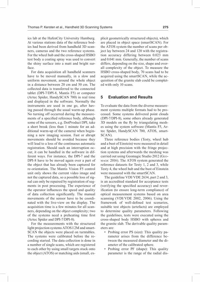
5.5 Reference Body Wheel Hub
The most complex and difficult reference body concerning this investigation is the wheel hub. Due to its symmetry, it can only be aligned clearly using a few small parts of the object, a grooved profile on the back and some elevat-ed letters inside. If these parts were not vis-ible in the data (e.g. of the DPI-7 LKA) due to low scan resolution, the object could not be aligned and compared to the reference object. With the exception of the HandySCAN 700 none of the investigated systems could gen-erate a complete model if the wheel hub was taken only from one position and not rotated. The 3D models from DPI-7/DPI-8 and from Artec Spider were not useful, since visually unacceptable models were generated. The fi-nal 3D models and the colour-coded differ-ences between test data and reference mod-
due to the complex geometry and all handheld structure light systems showed obvious sys-tematic scale differences (Fig. 6).
5.4 Reference Body Einstein Bust
The results of the 3D comparisons with the Einstein bust are summarized in Tab. 3 and presented in Fig. 7 in colour. The best numeri-cal and visual result is reached by the Handy-SCAN 700. From the DPI 7/DPI-8 and the Ar-tec Spider data, only models containing big holes could be created. The high deviations in the DPI-7/DPI-8 data show that they cannot cope with the homogeneous white surface of the Einstein bust. For this object the two high-er-assessed systems, Mantis F5 and Artec Spi-der, could not achieve the specifications quot-ed by the manufacturer in these tests.
Fig. 5: Quality parameter flatness measurement error (RE) equivalent to VDI/VDE 2634, part 2. Right fig.: BLUE – flatness measurement error, ORANGE: standard deviation (mm).
Tab. 2: Average deviations (Ø dev.) (mm) of the Testys – 3D comparison in Geomagic between reference (ATOS, # of triangles ca. 250.000) and test system, T = Testy, Sp = span.

Thomas P. Kersten et al., Handheld 3D Scanning Systems 279
6 Conclusion and Outlook
In this contribution the results of the compar-ative geometrical accuracy tests for different handheld 3D scanners were presented. The tests demonstrated that the evaluated middle class scanning systems currently do not reach the accuracies and the quality of the reference data produced by high-end structured light systems. The Creaform HandySCAN 700 is an exception, since the results of this high-end system are very close to the reference systems, i.e. it is a portable and flexible 3D scanner with almost the same accuracy as static structure light systems. However, it should be noted that not all of the selected reference bodies corre-sponded optimally to the typical range of ap-plications of the tested 3D scanners. In prin-ciple, the handling of these systems is simple.
el are shown in Fig. 8. This shows that the HandySCAN 700 delivered the best numerical and optical results. The visual impression is also confirmed by the results in Tab. 4, i.e. the HandySCAN 700 and the structured light pro-jection system ATOS (here used for compari-son) have the smallest average deviations. By contrast to this, the Mantis F5 shows signifi-cant systematic effects which might be caused by false scaling from system calibration. Man-tis F5 and Artec Spider could not achieve the manufacturer's accuracy specifications. The other systems achieve the specified accuracy, but they are rather unsuitable for this techni-cal application due to the optical quality of the generated model.
Fig. 6: Deviations (m) of the different Testys (3D comparison in Geomagic test data vs. reference) (from left to right) – DPI-7 dhp:i T2 (A), DPI-7 LKA T1 (B), DPI-8 T2 (D), Artec Spider T1 (E), Mantis F5 T3 (F) and HandySCAN 700 T2 (G).
Tab. 3: Average deviations (Ø dev.) (mm) of the Einstein bust – 3D comparison in Geomagic be-tween reference (smartSCAN, # of triangles 1,110,302) and test system, Sp = span.

280 Photogrammetrie • Fernerkundung • Geoinformation 5 – 6/2016
tems by a factor of 8-50. It can be concluded that the signal to noise ratio of the active scan-ning systems needs significant improvements. Comparing the latest DotProduct systems, the DPI-8 provides an improvement with respect to the DPI-7 only in the tests concerning the guideline VDI/VDE 2634.
The two systems Mantis F5 and Artec Spi-der settled in the middle price segment could not satisfy the accuracy specifications of their manufacturers in the investigations using the reference bodies Testy, wheel hub and Ein-stein bust. However, beside the pure accuracy values (average deviation and span), the visual quality and the completeness of the scanned test objects must also be considered as a cri-terion for the evaluation of the entire quality of an examined system. The visual quality of the models was better with the Mantis F5 than with the other handheld scanners. Using the data of the DPI-7/DPI-8 and the Artec Spider, no satisfying models of the reference bodies could be generated due to many holes in the dataset and noise of the point clouds.
However, the scanning by slow, homogeneous movements – around and over the object to be recorded – requires appropriate user experi-ence for keeping a permanent matching be-tween the scanned point clouds. The acquisi-tion speed of a few minutes for each object is quite high for all presented systems.
Following the guideline of VDI/VDE 2634, part 2 and 3, the determined quality param-eters (probing error and sphere-spacing er-ror) gave a clear indication that the instru-ment scale was not precisely determined for some handheld scanners and/or that the sen-sor is possibly not stable due to a mechanical-ly unstable structure. Procedures for the field check and/or simple self-calibration achieva-ble by any user are therefore both meaningful and necessary. The result of the flatness meas-urement error tests document that the image-based acquisition procedure with the Handy-SCAN 700 has very small deviations compared to the structured light systems, while the sys-tems with active projection show deviations that are larger than those of the reference sys-
Fig. 7: Deviations (m) of the different Einstein busts (3D comparison in Geomagic test data vs. reference) (from left to right) – DPI-7 dhp:I (A), DPI-7 LKA (B), DPI-8 (C), Artec Spider (D), Mantis F5 (E) and HandySCAN 700 (F). Scale identical to Fig. 6: green 0.1 mm, red +5 mm, blue -5 mm.
Tab. 4: Average deviations (Ø dev.) (mm) of the wheel hub – 3D comparison in Geomagic between reference (smartSCAN, # of triangles 6,352,367) and test system, Sp = span.
Thomas P. Kersten et al., Handheld 3D Scanning Systems 281
Although it is not documented in these in-vestigations, it was also noticed that the qual-ity of a model generated with a specific system has a strong dependence on the experience of the operator. Future investigations should be carried out in the context of alternative test scenarios, e.g. with larger reference bodies. Moreover, using those reference bodies and a test field a comparison with laser scanner measurements seems to also be meaningful, as generally the handheld systems will be able to fill a gap between high precision structured light systems (in comparison to high-end and middle class handheld 3D scanners) and ter-restrial laser scanners (in comparison to low-cost handheld 3D scanners).
Acknowledgements
The authors acknowledge the deployment of the 3D scanning systems by the State Office of Criminal Investigations Hamburg, Dr. Hesse and Partner Engineers (Hamburg), Hanack und Partner (Hamburg), AllTerra Deutschland GmbH (Schenefeld), and MexConsult (Bred-stedt). In particular, the energetic support dur-ing the data acquisition by the students of the master study program Geomatics of HCU Hamburg, the students of the Bochum Univer-sity of Applied Sciences and the staff of the State Office of Criminal Investigations Ham-burg is gratefully acknowledged. Further-more, the authors thank Martin MisgaisKi-Hass (Humboldt University Berlin) for pro-viding the four test bodies Testy.
References
adaMs, J.W., olaH, a., Mccurry, M.r. & Potze, s., 2015: Surface Model and Tomographic Ar-chive of Fossil Primate and Other Mammal Hol-otype and Paratype Specimens of the Ditsong National Museum of Natural History, Pretoria, South Africa. – PloS one 10 (10): e0139800.
aHern, c. & sPring, R., 2015: Handheld 3D Cap-ture. – GeoInformatics 18 (2): 18–19.
AICON3D, 2016: http://aicon3d.com/products/aicon-scanner.html (5.11.2016).
aMeteK, 2016: Creaform announces major design and performance upgrade for its new Metra-SCAN 3D laser scanner. – http://www.ametek.com/pressreleases/news/2016/april/creaformannouncesmajordesignandperformanceupgrade?news_lang=en (31.10.2016).
artec3D, 2016: https://www.artec3d.com/3d-scanner/artec-spider#specifications (2.11.2016).
batHoW, c. & breucKMann, b., 2011: High-defini-tion 3D acquisition of archaeological objects: An overview of various challenging projects all over the world. – 23rd CIPA Symposium: 12–16.
besl, P.J. & McKay, n.d., 1992: Method for regis-tration of 3-D shapes. – Robotics-DL tentative, International Society for Optics and Photonics: 586–606.
boeHM, J., 2014 Accuracy Investigation for Struc-tured-light Based Consumer 3D Sensors. – PFG – Photogrammetrie, Fernerkundung, Geoinfor-mation 2014 (2): 117–127.
cHan, t.o., licHti, d.d., belton, d., Klingeisen, b. & HelMHoltz, P., 2016: Survey Accuracy Analysis of a Hand-held Mobile LiDAR Device for Cultural Heritage Documentation. – PFG – Photogrammetrie, Fernerkundung, Geoinforma-tion 2016 (3): 153–165.
creaForM, 2016: http://www.creaform3d.com/en/metrology-solutions/portable-3d-scanner-handyscan-3d (2.11.2016).
dotProduct, 2016: https://www.dotproduct3d.com/assets/pdf/dotproduct-brochure_WEB.pdf (2.11.2016).
Fig. 8: Deviations (m) of different wheel hubs (3D comparison in Geomagic test data vs. refer-ence) (from left to right) – DPI-7 dhp:i (A), DPI-8 (B), Artec Spider (C), Mantis F5 (D) and Handy-SCAN 700 (E). Scale identical to Fig. 6: green 0.1 mm, red +5 mm, blue -5 mm.

282 Photogrammetrie • Fernerkundung • Geoinformation 5 – 6/2016
Comparative Geometrical Investigations of Handheld Scanning Systems. – International Archives of the Photogrammetry, Remote Sens-ing, and Spatial Information Sciences XLI-B5: 507–514.
KHosHelHaM, K., 2011: Accuracy Analysis of Ki-nect Depth Data. – The International Archives of the Photogrammetry, Remote Sensing and Spa-tial Information Sciences 38 (5/W12): 133–138.
OR3D, 2016: http://www.or3d.co.uk/wp-content/uploads/2016/09/F5-Short.pdf (5.11.2016).
ouiMet, c., gregg, J., Kretz, s., cHandler, c. & Hayes, J., 2015: Documentation and dissemina-tion of the sculptural elements of Canada’s Par-liamentary Buildings: Methodology develop-ment and evolution, a case study. – The Interna-tional Archives of the Photogrammetry, Remote Sensing and Spatial Information Sciences 40 (5): 347–352.
rau, J.y. & yeH, P.c., 2012: A semi-automatic im-age-based close range 3D modeling pipeline us-ing a multi-camera configuration. – Sensors 12 (8): 11271–11293.
reulKe, r. & MisgaisKi, M., 2012: Test body “Tes-ty” for Laser Scanning and Optical Systems. – PFG – Photogrammetrie, Fernerkundung, Geo-information 2012 (6): zum Titelbild.
slizeWsKi, a., Friess, M. & seMal, P., 2010: Sur-face scanning of anthropological specimens: nominal-actual comparison with low cost laser scanner and high end fringe light projection sur-face scanning systems. – Quartär 57: 179–187.
starosta, d., 2016: Untersuchung der Einsatzfähig-keit des 3D-Scanners „HandySCAN 700“. Bache-lor thesis, study program Geomatics, HafenCity University Hamburg, March.
VDI/VDE, 2002: Optical 3-D Measuring Systems – Optical Systems based on Area Scanning. VDI/VDE Guideline 2634, Part 2, Beuth Verlag, Berlin.
VDI/VDE, 2006: Optical 3-D Measuring Systems – Multiple View Systems based on Area Scan-ning. VDI/VDE Guideline 2634, Part 3, Beuth Verlag, Berlin.
Wrona, M., 2014: Using Optical NIR Handheld Scanner for Close Range 3D Mapping. – The 9th
International Conference on Environmental En-gineering 2014, Proceddia Engineering, Vilnius, Lithuania.
WuJanz, d., WeisbricH, s. & neitzel, F., 2011: 3D-Mapping mit dem Microsoft® Kinect Sensor – erste Untersuchungsergebnisse. – luHMann, T. & Müller, C. (eds.): Photogrammetrie, Laser-scanning, Optische 3D-Messtechnik, Beiträge der Oldenburger 3D-Tage 2011: 274–283, Wich-mann Verlag, Heidelberg.
zeiss, 2016: http://optotechnik.zeiss.com/ (2.11.2016).
FriedMan, c., Joel, b.W., scHult, a.r. & leFtWicH, M.c., 2015: Noninvasive 3D Geometry Extrac-tion of a Sea Lion Foreflipper. – Journal of Aero Aqua Bio-Mechanisms 4 (1): 25–31.
geoMagic, 2016: http://www.geomagic.com/en/ (2.11.2016).GOM, 2016: http://www.gom.com/de/messsysteme/
atos.html (2.11.2016).HieronyMus, J., MisgaisKi, M. & reulKe, r., 2011:
Genauigkeitsvergleich von 3D-Sensoren aus dem Freizeit- und Spielemarkt. – luHMann, t. & Müller, C. (eds.): Photogrammetrie, Laserscan-ning, Optische 3D-Messtechnik, Beiträge der Oldenburger 3D-Tage 2011: 232–241, Wichmann Verlag, Heidelberg.
inzerillo, l., di Mino, g., di Paola, F. & noto, s., 2015: The Diagnostics of Road Surface Distress-es Through Image-Based Modeling Techniques. – Experimental Survey on Laboratory-Rutted Samples. Life Safety and Security 3 (8): 31–35.
JaHraus, a., licHti, d. & daWson, P., 2015: Self-Calibration of a Structured Light Based Scanner for Use in Archeological Applications. – SPIE 9528, Videometrics, Range Imaging, and Appli-cations XIII: 95280E; doi: 10.1117/12.2184607.
Kersten, t., MecHelKe, K., lindstaedt, M. & sternberg, H., 2009: Methods for Geometric Ac-curacy Investigations of Terrestrial Laser Scan-ning Systems. – PFG – Photogrammetrie, Fern-erkundung, Geoinformation 2009 (4): 301–316.
Kersten, t., Keller, F., saenger, J. & scHieWe, J., 2012. Automated Generation of an Historic 4D City Model of Hamburg and its Visualisation with the GE Engine. – ioannides, M., FritscH, d., lleissner, J., daVies, r., reMondino, F. & caFFo, r. (eds.): EuroMed 2012 – International Conference on Cultural Heritage, Lecture Notes in Computer Science 7616: 55–65, Springer, Berlin und Heidelberg.
Kersten, t. & lindstaedt, M., 2012: Image-Based Low Cost Systems for Automatic 3D Recording and Modelling of Archaeological Finds and Ob-jects. – ioannides, M., FritscH, d., lleissner, J., daVies, r., reMondino, F. & caFFo, r. (eds.): EuroMed 2012 – International Conference on Cultural Heritage, Lecture Notes in Computer Science 7616: 1–10, Springer, Berlin und Heidel-berg.
Kersten, t., oMelanoWsKy, d. & lindstaedt, M., 2016a: Investigations of Low-Cost Systems for 3D Reconstruction of Small Objects. – ioan-nides, M., FinK, e., MoroPoulou, a., Hagedorn-sauPe, M., Fresa, a., liestøl, g., raJcic, V. & grussenMeyer, P. (eds.): EuroMed 2016, Part I, Lecture Notes in Computer Science 10058: 1–12, Springer International Publishing AG.
Kersten, t., Przybilla, H.-J., lindstaedt, M., tscHirscHWitz, F. & MisgaisKi-Hass, M., 2016b:

Thomas P. Kersten et al., Handheld 3D Scanning Systems 283
Addresses of the Authors:tHoMas P. Kersten, Maren lindstaedt, HafenCity
Universität Hamburg, Labor für Photogram-metrie & Laserscanning, Überseeallee 16, D-20457 Hamburg, Tel.: +49-40-42827-5343, e-mail: thomas.Kersten, [email protected]
Heinz-Jürgen Przybilla, Hochschule Bochum, Fachbereich Geodäsie, Labor für Photogram-metrie, Lennershofstraße 140, D-44801 Bochum, e-mail: [email protected]
Manuskript eingereicht: Oktober 2016Angenommen: Oktober 2016
zHang, W., Wang, c. & Xi, X., 2015: 3D Scan of Ornamental Column (huabiao) Using Terrestrial LiDAR and Handheld Imager. – The Interna-tional Archives of the Photogrammetry, Remote Sensing and Spatial Information Sciences 40 (5/W7): 491–494.


![An Overview on Homomorphic Encryption Algorithmsreltech/PFG/2018/PFG-18-28.pdfnew ideas [17], [21]. In parallel, some applications were developed to operate on data encrypted by those](https://static.fdocuments.in/doc/165x107/5f49432cc8cab04d5164b934/an-overview-on-homomorphic-encryption-algorithms-reltechpfg2018pfg-18-28pdf.jpg)


