Investigation of Options for Damping Trapped IVU Resonances
4
INVESTIGATION OF OPTIONS FOR DAMPING TRAPPED IVU RESONANCES R. T. Dowd * , Australian Synchrotron - ASNTO, Melbourne, Australia J. Chi, D. Pelz, Radio Frequency Systems (RFS), Melbourne, Australia Abstract Trapped resonances have been observed within the three In-Vacuum Undulators (IVUs) insertion devices at the Aus- tralian Synchrotron. These resonances can create vertical beam instability if not controlled through transverse feed- back systems. Similar resonances have been observed at other synchrotron light sources around the world. Under certain conditions of undulator gap, these resonances can couple quite strongly to the beam, requiring high feedback gain. An investigation of the resonances has been carried out using 3D eigenmode and wakefield simulations to un- derstand the resonances and determine the effectiveness of various schemes for modifying the damping the resonances. INTRODUCTION As shown in previous studies at the Australian Syn- chrotron [1], we have observed sharp vertical resonances within our in-vacuum undulators (IVUs) when set to spe- cific gaps. These resonances cause beam instability unless damped. Other Light sources have also observed similar phenomena [2] [3]. Further investigation of the beam resonances in the undu- lators using grow-damp measurements at gap intervals of 0.005 mm is shown in figure 1. The progression of the in- stability mode number and the decreasing strength with in- creasing gap can be seen clearly, which indicates a loaded waveguide type resonance is present (with the resonant fre- quency determined by the undulator gap). The presence of more than one resonances is also indicated by the various gap intervals of different instability mode series’. While we are currently using transverse feedback to damp the resonances, we will be installing more IVU de- vices in the future and it is not certain that the feedback would be able to stabilise multiple strong resonances simul- taneously. We would therefore like to understand and, if possible, devise a way of eliminating these resonances from our current and future undulator devices. RESONANCE STUDY Previous attempts to model the IVUs ran into were hin- dered because we did not have the local computing re- sources to simulate the full device. We partnered with the local branch of Radio Frequency Systems (RFS), who have expertise in RF simulations and the computing resources necessary. * [email protected] Figure 1: Instability mode growth rate vs IVU gap for the 2 metre IVU (left) and 3 metre IVU (right). Intensity scale has not been normalised. IVU Model An accurate 3D model of the IVU chamber for the 2 me- tre (IVU05) and 3 metre (IVU03, IVU13) devices was used in both the eigenmode and wakefield simulations in order to get the most accurate possible results. A cutaway view of the IVU05 model is shown in Figure 2. The only major approximation in the model is the curve of the taper transi- tion pieces at each end, with straight line segments approx- imating the curve, based on photos taken of the taper in op- eration. The model allows for the magnet array gap to be moved between 6mm and 10mm so that we can study the effect of the changing gap. Figure 2: Geometry of the model for IVU05 used in simu- lations. Observed Resonances The results of the eigenmode simulations for each device are shown in table 1. The main problematic resonance in the 2 metre device has a tuning gradient of about 4.6 MHz/mm at 8mm gap, which corresponds well to simulated mode 3. For the 3 metre device, modes 4 and 5 correspond well to the tuning gradient of the two main observed instability modes. The spacial field distributions of the resonances are quite similar, with both the E and H fields largely concentrated in the magnet array gap. Typical field distribution is shown in Fig. 3 and 4. 9th International Particle Accelerator Conference IPAC2018, Vancouver, BC, Canada JACoW Publishing ISBN: 978-3-95450-184-7 doi:10.18429/JACoW-IPAC2018-TUPMF021 TUPMF021 1296 Content from this work may be used under the terms of the CC BY 3.0 licence (© 2018). Any distribution of this work must maintain attribution to the author(s), title of the work, publisher, and DOI. 02 Photon Sources and Electron Accelerators T15 Undulators and Wigglers
Transcript of Investigation of Options for Damping Trapped IVU Resonances
INVESTIGATION OF OPTIONS FOR DAMPING TRAPPED IVU
RESONANCES
R. T. Dowd∗, Australian Synchrotron - ASNTO, Melbourne, Australia
J. Chi, D. Pelz, Radio Frequency Systems (RFS), Melbourne, Australia
Abstract
Trapped resonances have been observed within the three
In-Vacuum Undulators (IVUs) insertion devices at the Aus-
tralian Synchrotron. These resonances can create vertical
beam instability if not controlled through transverse feed-
back systems. Similar resonances have been observed at
other synchrotron light sources around the world. Under
certain conditions of undulator gap, these resonances can
couple quite strongly to the beam, requiring high feedback
gain. An investigation of the resonances has been carried
out using 3D eigenmode and wakefield simulations to un-
derstand the resonances and determine the effectiveness of
various schemes for modifying the damping the resonances.
INTRODUCTION
As shown in previous studies at the Australian Syn-
chrotron [1], we have observed sharp vertical resonances
within our in-vacuum undulators (IVUs) when set to spe-
cific gaps. These resonances cause beam instability unless
damped. Other Light sources have also observed similar
phenomena [2] [3].
Further investigation of the beam resonances in the undu-
lators using grow-damp measurements at gap intervals of
0.005 mm is shown in figure 1. The progression of the in-
stability mode number and the decreasing strength with in-
creasing gap can be seen clearly, which indicates a loaded
waveguide type resonance is present (with the resonant fre-
quency determined by the undulator gap). The presence of
more than one resonances is also indicated by the various
gap intervals of different instability mode series’.
While we are currently using transverse feedback to
damp the resonances, we will be installing more IVU de-
vices in the future and it is not certain that the feedback
would be able to stabilise multiple strong resonances simul-
taneously. We would therefore like to understand and, if
possible, devise a way of eliminating these resonances from
our current and future undulator devices.
RESONANCE STUDY
Previous attempts to model the IVUs ran into were hin-
dered because we did not have the local computing re-
sources to simulate the full device. We partnered with the
local branch of Radio Frequency Systems (RFS), who have
expertise in RF simulations and the computing resources
necessary.
Figure 1: Instability mode growth rate vs IVU gap for the
2 metre IVU (left) and 3 metre IVU (right). Intensity scale
has not been normalised.
IVU Model
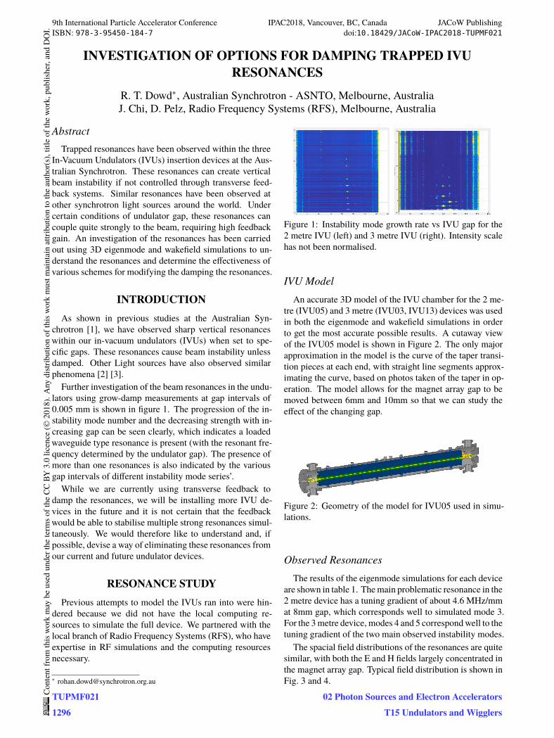
An accurate 3D model of the IVU chamber for the 2 me-
tre (IVU05) and 3 metre (IVU03, IVU13) devices was used
in both the eigenmode and wakefield simulations in order
to get the most accurate possible results. A cutaway view
of the IVU05 model is shown in Figure 2. The only major
approximation in the model is the curve of the taper transi-
tion pieces at each end, with straight line segments approx-
imating the curve, based on photos taken of the taper in op-
eration. The model allows for the magnet array gap to be
moved between 6mm and 10mm so that we can study the
effect of the changing gap.
Figure 2: Geometry of the model for IVU05 used in simu-
lations.
Observed Resonances
The results of the eigenmode simulations for each device
are shown in table 1. The main problematic resonance in the
2 metre device has a tuning gradient of about 4.6 MHz/mm
at 8mm gap, which corresponds well to simulated mode 3.
For the 3 metre device, modes 4 and 5 correspond well to the
tuning gradient of the two main observed instability modes.
The spacial field distributions of the resonances are quite
similar, with both the E and H fields largely concentrated in
the magnet array gap. Typical field distribution is shown in
Fig. 3 and 4.
9th International Particle Accelerator Conference IPAC2018, Vancouver, BC, Canada JACoW PublishingISBN: 978-3-95450-184-7 doi:10.18429/JACoW-IPAC2018-TUPMF021
TUPMF0211296
Cont
entf
rom
this
wor
km
aybe
used
unde
rthe
term
soft
heCC
BY3.
0lic
ence
(©20
18).
Any
distr
ibut
ion
ofth
isw
ork
mus
tmai
ntai
nat
tribu
tion
toth
eau
thor
(s),
title
ofth
ew
ork,
publ
isher
,and
DO
I.
02 Photon Sources and Electron AcceleratorsT15 Undulators and Wigglers
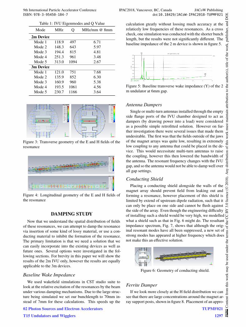
Table 1: IVU Eigenmodes and Q Value
Mode MHz Q MHz/mm @ 8mm
2m Device
Mode 1 118.9 497 6.71
Mode 2 148.3 643 5.97
Mode 3 194.4 815 4.81
Mode 4 251.3 961 3.48
Mode 5 313.0 1094 2.67
3m Device
Mode 1 121.0 751 7.68
Mode 2 135.9 852 6.30
Mode 3 160.9 960 5.38
Mode 4 193.5 1061 4.56
Mode 5 230.7 1166 3.64
Figure 3: Transverse geometry of the E and H fields of the
resonance
Figure 4: Longitudinal geometry of the E and H fields of
the resonance
DAMPING STUDY
Now that we understand the spatial distribution of fields
of these resonances, we can attempt to damp the resonance
via insertion of some kind of lossy material, or use a con-
ducting material to inhibit the formation of the resonance.
The primary limitation is that we need a solution that we
can easily incorporate into the existing devices as well as
future ones. Several options were investigated in the fol-
lowing sections. For brevity in this paper we will show the
results of the 2m IVU only, however the results are equally
applicable to the 3m devices.
Baseline Wake Impedance
We used wakefield simulations in CST studio suite to
look at the relative excitation of the resonances by the beam
under various damping mechanisms. Due to the large struc-
ture being simulated we set our bunchlength to 70mm in-
stead of 7mm for these calculations. This speeds up the
calculation gteatly without loosing much accuracy at the
relaticely low frequencies of these resonances. As a cross
check, one simulation was conducted with the shorter bunch
length, but the results were not significantly different. The
baseline impedance of the 2 m device is shown in figure 5.
Figure 5: Baseline transverse wake impedance (Y) of the 2 m undulator at 6mm gap.
Antenna Dampers
Single or multi-turn antennas installed through the empty side flange ports of the IVU chamber designed to act as dampers (by drawing power into a load) were considered as a possible simple retrofitted solution. However on fur-
ther investigation there were several issues that made them undesirable. The first was that the fields outside of the jaws of the magnet arrays was quite low, resulting in extremely low coupling to any antenna that could be placed in the de-
vice. This would necessitate multi-turn antennas to raise the coupling, however this then lowered the bandwidth of the antenna. The resonant frequency changes with the IVU gap, and so the antenna would not be able to damp well over all gap settings.
Conducting Shield
Placing a conducting shield alongside the walls of the magnet array should prevent field from leaking out and forming a resonance, however placement of this shield is limited by extend of upstream dipole radiation, such that it can only be place on one side and cannot be flush against the side of the array. Even though the engineering difficulty of installing such a shield would be very high, we modelled what a shield such as that in Fig. 6 might do. The resultant impedance spectrum, Fig. 7, shows that although the orig-
inal resonant modes have all been suppressed, a new set of strong modes has appeared at higher frequency which does not make this an effective solution.
Figure 6: Geometry of conducting shield.
Ferrite Damper
If we look more closely at the H field distribution we can
see that there are large concentrations around the magnet ar-
ray support posts, shown in figure 8. Placement of an appro-
9th International Particle Accelerator Conference IPAC2018, Vancouver, BC, Canada JACoW PublishingISBN: 978-3-95450-184-7 doi:10.18429/JACoW-IPAC2018-TUPMF021
02 Photon Sources and Electron AcceleratorsT15 Undulators and Wigglers
TUPMF0211297
Cont
entf
rom
this
wor
km
aybe
used
unde
rthe
term
soft
heCC
BY3.
0lic
ence
(©20
18).
Any
distr
ibut
ion
ofth
isw
ork
mus
tmai
ntai
nat
tribu
tion
toth
eau
thor
(s),
title
ofth
ew
ork,
publ
isher
,and
DO
I.
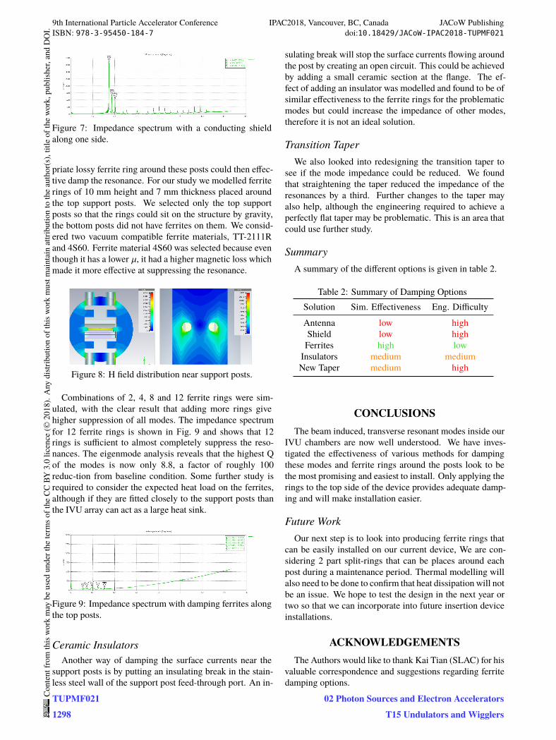
Figure 7: Impedance spectrum with a conducting shield
along one side.
priate lossy ferrite ring around these posts could then effec-
tive damp the resonance. For our study we modelled ferrite
rings of 10 mm height and 7 mm thickness placed around
the top support posts. We selected only the top support
posts so that the rings could sit on the structure by gravity,
the bottom posts did not have ferrites on them. We consid-
ered two vacuum compatible ferrite materials, TT-2111R
and 4S60. Ferrite material 4S60 was selected because even
though it has a lower µ, it had a higher magnetic loss which
made it more effective at suppressing the resonance.
Figure 8: H field distribution near support posts.
Combinations of 2, 4, 8 and 12 ferrite rings were sim-
ulated, with the clear result that adding more rings give higher suppression of all modes. The impedance spectrum for 12 ferrite rings is shown in Fig. 9 and shows that 12 rings is sufficient to almost completely suppress the reso-
nances. The eigenmode analysis reveals that the highest Q of the modes is now only 8.8, a factor of roughly 100 reduc-tion from baseline condition. Some further study is required to consider the expected heat load on the ferrites, although if they are fitted closely to the support posts than the IVU array can act as a large heat sink.
Figure 9: Impedance spectrum with damping ferrites along
the top posts.
Ceramic Insulators
Another way of damping the surface currents near the
support posts is by putting an insulating break in the stain-
less steel wall of the support post feed-through port. An in-
sulating break will stop the surface currents flowing around
the post by creating an open circuit. This could be achieved
by adding a small ceramic section at the flange. The ef-
fect of adding an insulator was modelled and found to be of
similar effectiveness to the ferrite rings for the problematic
modes but could increase the impedance of other modes,
therefore it is not an ideal solution.
Transition Taper
We also looked into redesigning the transition taper to
see if the mode impedance could be reduced. We found
that straightening the taper reduced the impedance of the
resonances by a third. Further changes to the taper may
also help, although the engineering required to achieve a
perfectly flat taper may be problematic. This is an area that
could use further study.
Summary
A summary of the different options is given in table 2.
Table 2: Summary of Damping Options
Solution Sim. Effectiveness Eng. Difficulty
Antenna low high
Shield low high
Ferrites high low
Insulators medium medium
New Taper medium high
CONCLUSIONS
The beam induced, transverse resonant modes inside our
IVU chambers are now well understood. We have inves-
tigated the effectiveness of various methods for damping
these modes and ferrite rings around the posts look to be
the most promising and easiest to install. Only applying the
rings to the top side of the device provides adequate damp-
ing and will make installation easier.
Future Work
Our next step is to look into producing ferrite rings that
can be easily installed on our current device, We are con-
sidering 2 part split-rings that can be places around each
post during a maintenance period. Thermal modelling will
also need to be done to confirm that heat dissipation will not
be an issue. We hope to test the design in the next year or
two so that we can incorporate into future insertion device
installations.
ACKNOWLEDGEMENTS
The Authors would like to thank Kai Tian (SLAC) for his
valuable correspondence and suggestions regarding ferrite
damping options.
9th International Particle Accelerator Conference IPAC2018, Vancouver, BC, Canada JACoW PublishingISBN: 978-3-95450-184-7 doi:10.18429/JACoW-IPAC2018-TUPMF021
TUPMF0211298
Cont
entf
rom
this
wor
km
aybe
used
unde
rthe
term
soft
heCC
BY3.
0lic
ence
(©20
18).
Any
distr
ibut
ion
ofth
isw
ork
mus
tmai
ntai
nat
tribu
tion
toth
eau
thor
(s),
title
ofth
ew
ork,
publ
isher
,and
DO
I.
02 Photon Sources and Electron AcceleratorsT15 Undulators and Wigglers
REFERENCES
[1] R.Dowd et. al Investigation of Trapped Resonant Modes in
Insertion Devices at the Australian Synchrotron, Proceedings
IPAC’16, TUPOR023 May 2016, Busan, South Korea.
[2] R. Bartolini et. al Analysis of Milti-Bunch Instabilities at the
Diamond Storage Ring, Proceedings IPAC’16, TUPOR013
May 2016, Busan, South Korea.
[3] K. Tian et. al Investigation of Transverse Beam Instabiltiy by
an In-Vacuum Undulator at SPEAR3, SLAC-PUB-16824.
9th International Particle Accelerator Conference IPAC2018, Vancouver, BC, Canada JACoW PublishingISBN: 978-3-95450-184-7 doi:10.18429/JACoW-IPAC2018-TUPMF021
02 Photon Sources and Electron AcceleratorsT15 Undulators and Wigglers
TUPMF0211299
Cont
entf
rom
this
wor
km
aybe
used
unde
rthe
term
soft
heCC
BY3.
0lic
ence
(©20
18).
Any
distr
ibut
ion
ofth
isw
ork
mus
tmai
ntai
nat
tribu
tion
toth
eau
thor
(s),
title
ofth
ew
ork,
publ
isher
,and
DO
I.