
Investigation of Freeze Linings in Copper … of Freeze Linings in Copper Containing Slag Systems...
14
Investigation of Freeze Linings in Copper Containing Slag Systems Ata FALLAH MEHRJARDI, Peter C. HAYES, Evgueni JAK Pyrometallurgy Research Centre, The University of Queensland, Brisbane, Australia Abstract: Slag freeze linings are increasingly used in industrial pyrometallurgical processes to ensure furnace integrity is maintained in aggressive high temperature environments. Most previous studies of freeze linings have analysed the formation of slag deposits based on heat transfer models. The focus of the present research is to determine the impact of chemistry on the microstructures, thickness, stability and heat transfer characteristics of the frozen deposit. The formation of the freeze linings is studied under controlled laboratory conditions using an air-cooled “cold finger” that is immersed into a synthetic slag bath heated in an induction furnace. The temperature profile across the deposit is also been measured. A Cu-Fe-Si-Al-O slag has been selected for study; the primary phase for the slag has been shown to be delafossite and liquidus temperature of the slag has been determined. The phase assemblages and microstructures of the deposits formed in the cold finger experiments differ significantly from those anticipated from equilibrium cooling of the slag. The freeze lining deposits have been found in general to consist of several different layers. Starting from the cold wall these layers consist of glass; glass with microcrystalline precipitates; multiphase sub-liquidus material containing delafossite and cuprite crystal phase assemblages and high-silica metastable liquid that was separated from the bulk liquid (closed layers); phase assemblages containing delafossite and cuprite crystals and a high-silica liquid phase that is connected to the bulk liquid (open layers), and the outer layer containing a complex mixture of liquid and solid phases. The findings have significant practical implications, and potential for the improved design and operation of industrial metallurgical furnaces. Key words: Freeze lining, copper smelting, deposit, copper containing slag system 1. Introduction Methods of increasing productivity have always been challenging issues for pyrometallurgical processes. Increasing the throughput of the reactor through the use of higher process temperature and vigorous agitation in the bath are possible options for enhancing the kinetics of reactions in multi-phase systems [1-3]. On the other hand, these measures also lead to rapid degradation of the refractory and premature shutdown of the reactor for relining, imposing additional costs on processes in the form of planned and unplanned maintenance. An alternative solution to this problem is the formation of a slag freeze lining rather than direct contact of refractory layers with the hot bath. A freeze lining is a solidified layer of slag bath, as material formed on the cooled wall of a furnace due to the removal of heat from the bath side, as depicted in Figure 1. This steady-state layer then protects the water or air-cooled jackets or refractory of the furnace from mechanical, chemical and thermal attack [3, 4].
Transcript of Investigation of Freeze Linings in Copper … of Freeze Linings in Copper Containing Slag Systems...

Investigation of Freeze Linings in Copper Containing Slag Systems
Ata FALLAH MEHRJARDI, Peter C. HAYES, Evgueni JAK Pyrometallurgy Research Centre, The University of Queensland, Brisbane, Australia
Abstract: Slag freeze linings are increasingly used in industrial pyrometallurgical processes to ensure furnace integrity
is maintained in aggressive high temperature environments. Most previous studies of freeze linings have analysed the
formation of slag deposits based on heat transfer models. The focus of the present research is to determine the impact of
chemistry on the microstructures, thickness, stability and heat transfer characteristics of the frozen deposit. The
formation of the freeze linings is studied under controlled laboratory conditions using an air-cooled “cold finger” that is
immersed into a synthetic slag bath heated in an induction furnace. The temperature profile across the deposit is also
been measured.
A Cu-Fe-Si-Al-O slag has been selected for study; the primary phase for the slag has been shown to be delafossite
and liquidus temperature of the slag has been determined. The phase assemblages and microstructures of the deposits
formed in the cold finger experiments differ significantly from those anticipated from equilibrium cooling of the slag.
The freeze lining deposits have been found in general to consist of several different layers. Starting from the cold wall
these layers consist of glass; glass with microcrystalline precipitates; multiphase sub-liquidus material containing
delafossite and cuprite crystal phase assemblages and high-silica metastable liquid that was separated from the bulk
liquid (closed layers); phase assemblages containing delafossite and cuprite crystals and a high-silica liquid phase that is
connected to the bulk liquid (open layers), and the outer layer containing a complex mixture of liquid and solid phases.
The findings have significant practical implications, and potential for the improved design and operation of industrial
metallurgical furnaces.
Key words: Freeze lining, copper smelting, deposit, copper containing slag system
1. Introduction
Methods of increasing productivity have always been challenging issues for pyrometallurgical processes. Increasing
the throughput of the reactor through the use of higher process temperature and vigorous agitation in the bath are
possible options for enhancing the kinetics of reactions in multi-phase systems [1-3]. On the other hand, these measures
also lead to rapid degradation of the refractory and premature shutdown of the reactor for relining, imposing additional
costs on processes in the form of planned and unplanned maintenance. An alternative solution to this problem is the
formation of a slag freeze lining rather than direct contact of refractory layers with the hot bath. A freeze lining is a
solidified layer of slag bath, as material formed on the cooled wall of a furnace due to the removal of heat from the bath
side, as depicted in Figure 1. This steady-state layer then protects the water or air-cooled jackets or refractory of the
furnace from mechanical, chemical and thermal attack [3, 4].

Figure 1: Schematic representation of heat transfer through the freeze lining [2]
The challenge in using freeze linings for stable operation of the furnace consists of maintaining a stable frozen layer
of an acceptable thickness inside the furnace wall. Thick layers may result in a drastic decrease of the reactor volume.
Thin layers may lead to increased heat losses through the wall, frequent detachment of the freeze lining from the
furnace shell, and increased risk to the furnace integrity.
A review of heat transfer models of freeze linings has revealed that thermal parameters, such as, bath convection,
superheat and the heat-removing capacity of the coolant from the interface of the deposit and bath are the main
parameters determining the thickness of the freeze lining in the steady-state conditions. These models presuppose that
the liquidus temperature defines the interface between stable freeze lining and the bath [2, 5].
Freeze linings are already in use in a number of important industrial applications such as, zinc slag fuming system,
Hall- Héroult (aluminium production), ilmenite smelting processes, copper flash and electric furnace - Olympic Dam
Operation [1, 6-8]. Laboratory-scale deposit and industrial samples have been studied [9, 10]; the thickness,
microstructure and composition of the deposit were the focus of those studies. There are, however, only a few published
papers that discuss the effect of chemistry on deposit formation [1, 6, 7, 11, 12].
2. Experimental Methodology
To gain a better understanding of freeze lining formation and the effects of process variables on the stability,
thickness and heat transfer characteristics of the frozen deposit, experimental laboratory studies of freeze lining
formation using cold finger tests have been used in conjunction with supporting complementary experiments. A 1-D
heat transfer model in cylindrical coordinates was used to predict the thickness and temperature distribution in the
freeze lining as a function of key process variables, such as, coolant flowrate, thermal conductivity, bath convection,
bath temperature and bath-deposit interface temperature.
2.1 Cold Finger Experiments
The air-cooled probe or “cold finger” technique has been selected to investigate the formation of freeze linings in the
present study [1, 3, 12], this involves melting the slag in the induction furnace, freeze lining formation on immersing the
cold finger in the liquid slag, quench and microstructural analysis of the deposit.
Synthetic slags were prepared from high purity (99.9%) oxide powders of Cu2O (75 wt pct), SiO2 (12 wt pct) and
Fe2O3 (13 wt pct) to have a liquidus temperature approximately 1150oC [13]. Figure 2.a shows schematically the
apparatus used for the investigation of freeze lining formation. Heating of the synthesized slag is achieved using an
electrical induction furnace. To provide the heat to the slag, an alumina crucible was placed in the graphite susceptor. A
type-R thermocouple (100%Pt and Pt.13% Rd) was used to measure the temperature in the bath. This thermocouple was
connected to the induction furnace through a temperature process controller to keep the temperature of the liquid bath
constant during the experiment.
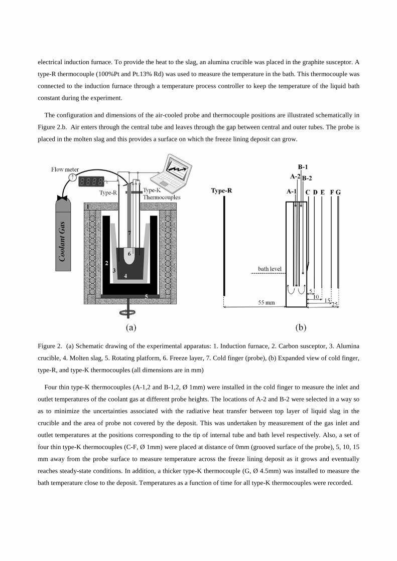
The configuration and dimensions of the air-cooled probe and thermocouple positions are illustrated schematically in
Figure 2.b. Air enters through the central tube and leaves through the gap between central and outer tubes. The probe is
placed in the molten slag and this provides a surface on which the freeze lining deposit can grow.
Figure 2. (a) Schematic drawing of the experimental apparatus: 1. Induction furnace, 2. Carbon susceptor, 3. Alumina
crucible, 4. Molten slag, 5. Rotating platform, 6. Freeze layer, 7. Cold finger (probe), (b) Expanded view of cold finger,
type-R, and type-K thermocouples (all dimensions are in mm)
Four thin type-K thermocouples (A-1,2 and B-1,2, Ø 1mm) were installed in the cold finger to measure the inlet and
outlet temperatures of the coolant gas at different probe heights. The locations of A-2 and B-2 were selected in a way so
as to minimize the uncertainties associated with the radiative heat transfer between top layer of liquid slag in the
crucible and the area of probe not covered by the deposit. This was undertaken by measurement of the gas inlet and
outlet temperatures at the positions corresponding to the tip of internal tube and bath level respectively. Also, a set of
four thin type-K thermocouples (C-F, Ø 1mm) were placed at distance of 0mm (grooved surface of the probe), 5, 10, 15
mm away from the probe surface to measure temperature across the freeze lining deposit as it grows and eventually
reaches steady-state conditions. In addition, a thicker type-K thermocouple (G, Ø 4.5mm) was installed to measure the
bath temperature close to the deposit. Temperatures as a function of time for all type-K thermocouples were recorded.
The air-cooled probe is rapidly dipped into the molten slag. After a selected period of immersion, the probe was pulled
out of the bath and quenched into water. The rate of freeze lining growth was found to be dependent on the air flow rate,
immersion time and rotation speed of the crucible.
2.2 Supporting Experiments
Initial experiments have indicated that significant quantities of Al2O3 dissolve in the molten slag from the alumina
crucible. Analysis of phase equilibria in the “Cu2O”-“Fe2O3”-SiO2-Al2O3 system is, therefore, important. In addition
preliminary results indicated that the kinetics of crystallisation can play a crucial role in the formation of the phases.
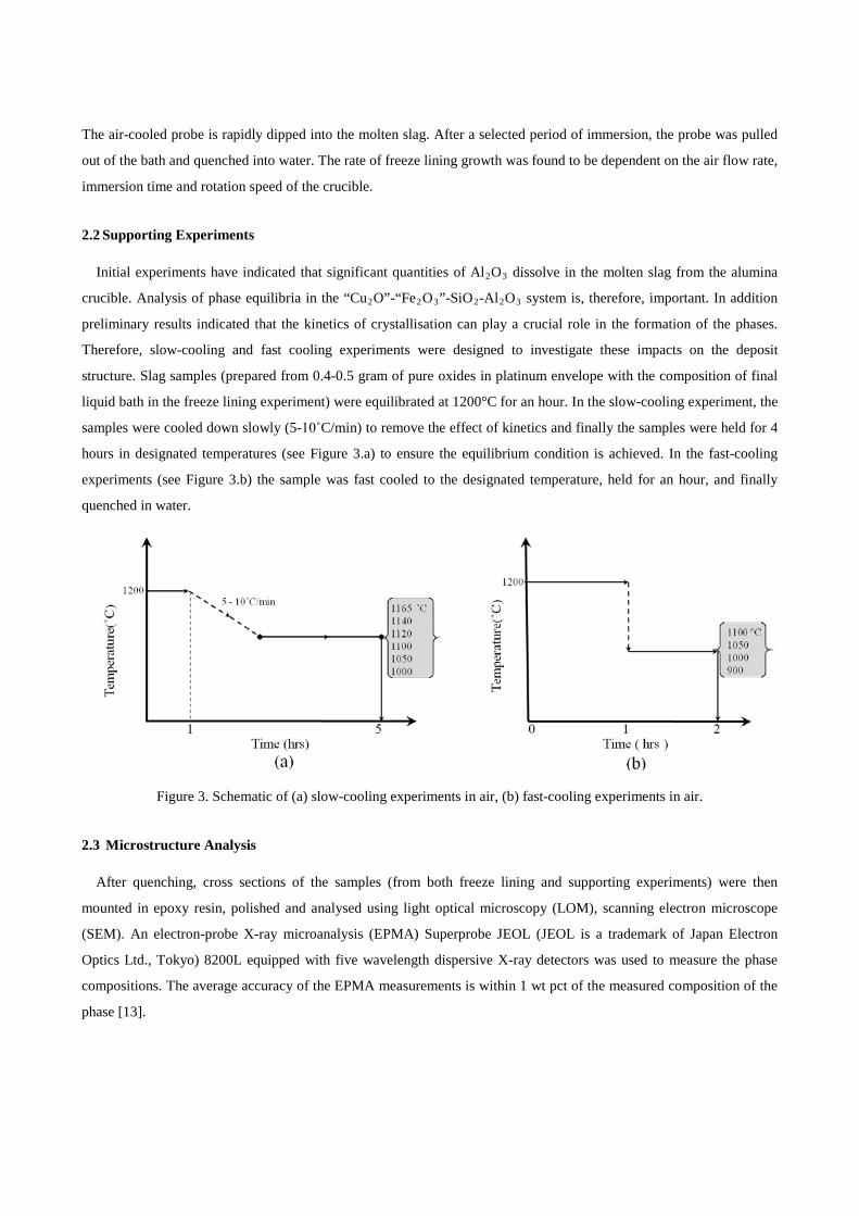
Therefore, slow-cooling and fast cooling experiments were designed to investigate these impacts on the deposit
structure. Slag samples (prepared from 0.4-0.5 gram of pure oxides in platinum envelope with the composition of final
liquid bath in the freeze lining experiment) were equilibrated at 1200°C for an hour. In the slow-cooling experiment, the
samples were cooled down slowly (5-10˚C/min) to remove the effect of kinetics and finally the samples were held for 4
hours in designated temperatures (see Figure 3.a) to ensure the equilibrium condition is achieved. In the fast-cooling
experiments (see Figure 3.b) the sample was fast cooled to the designated temperature, held for an hour, and finally
quenched in water.
Figure 3. Schematic of (a) slow-cooling experiments in air, (b) fast-cooling experiments in air.
2.3 Microstructure Analysis
After quenching, cross sections of the samples (from both freeze lining and supporting experiments) were then
mounted in epoxy resin, polished and analysed using light optical microscopy (LOM), scanning electron microscope
(SEM). An electron-probe X-ray microanalysis (EPMA) Superprobe JEOL (JEOL is a trademark of Japan Electron
Optics Ltd., Tokyo) 8200L equipped with five wavelength dispersive X-ray detectors was used to measure the phase
compositions. The average accuracy of the EPMA measurements is within 1 wt pct of the measured composition of the
phase [13].

3. Results
3.1 Slow-Cooling Equilibrium Experiment
Slow-cooling equilibrium experiments were carried out in air (see Figure 3.a). The primary phase is found to be
spinel and this phase first appears at temperatures between 1165 and 1140˚C (see Figure 4.a and b). Other phases
including delafossite, tridymite and copper (II) oxide were found to precipitate out at temperatures between 1050 and
1000˚C (Figure 4.d, e). Spinel compositions measured with EPMA indicate the presence of extensive solid solution with
concentrations of CuO, Fe2O3 and Al2O3 corresponding to the chemical formula of (Cu+2,Fe+2)O.(Fe+3,Al+3)2O3.
Figure 4. Microstructures of slags treated in slow-cooling experiments in air, 4 hours equilibration time (see Table 1 for the bulk liquid composition).
3.2 Fast-Cooling Kinetic Experiments
Fast-cooling experiments (see Figure 3.b) were undertaken to investigate the role of kinetics on the stability and
structure of crystalline phases. Figure 5.a, b show that spinel forms as a primary phase crystal from 1100 to 1050˚C only
on the surface of the sample, that is, where the slag is in a good contact with air and the oxygen concentration is high.
Approximately 200 µm underneath of the sample surface, delafossite is observed. Delafossite, cuprite and silicate slag
were observed (see Figure 5.c) in the fast-cooling experiments undertaken down to 1000˚C. EPMA measurements
indicate that a solid solution contained iron and aluminium exists in the delafossite corresponding to the chemical
formula of Cu2O.(Al+3, Fe+3)2O3.
Figure 5. Microstructures of slags treated in fast-cooling experiments in air(see Table 1 for the bulk liquid composition).

3.3 Heat Flow Model of Freeze Lining
Figure 6 shows an example of the deposit formed on the surface of the cold finger; the cross section of the deposit is
used to determine the thickness of the freeze lining after a given immersion time. For the deposit obtained with bulk
slag temperature 1165˚C, air flow rate 100 l/min, speed of rotation 20 RPM the recorded temperatures across the section
remain constant after 70 minutes of probe immersion (see Figure 7.a) suggesting that the freeze lining reaches a steady-
state thickness at this time.
Figure 6. Macro images of the deposit formed at bath temperature: 1165˚C, air flow rate: 150 l/min, speed of rotation:
20 RPM and immersion time: 1.5 hours.
Figure 7.a shows air inlet and outlet temperatures inside the cold finger as a function of submergence time. The inlet
temperature measured by the thermocouple A-2 is greater than that of outlet (B-2), most likely due to the radiation from
the probe inner surface and does not correspond to the air temperature. There is approximately 10 to 15˚C difference
between B-1 and B-2 in the steady-state conditions, which could be the result of radiative heat transfer to the body of
cold finger.
Figure 7. Temperature vs. immersion time at bath temperature: 1165˚C, air flow rate: 150 l/min, speed of rotation: 20
RPM and immersion times: 1.5 hours (a) air inlet and outlet temperatures at different thermocouple positions (b) across
the width of the deposit and bath.

The temperature distribution in the deposit as a function of distance from the probe surface at steady-state conditions
(see Figure 8) was derived through interpolation of measured temperatures, detected by the thermocouples (see Figure
7.b). This information is needed to explain trends of composition and temperature of the observed phases across the
deposit with reference to the phase equilibria study of the “Cu2O”-“Fe2O3”-SiO2-Al2O3 in air and equilibrium with
metallic copper. The bath temperature during the experiment was constant and yet a thermal gradient across the bath
from deposit-bath interface to 6 mm away into the bath was observed, recorded by a type-K thermocouple in the
position of 25 mm away probe surface (see Figure 7.b).
Figure 8. Temperature distribution across the deposit and bath at steady-state conditions (bath temperature: 1165˚C, air
flow rate: 150 l/min, speed of rotation: 20 RPM and immersion time: 1.5 hours)
Obtaining detailed measurements of the temperatures across the deposit thickness enables estimation of thermal-
related parameters, such as, the effective thermal conductivity of the freeze lining for the given bulk bath composition
and the convection heat transfer coefficients at the bath/deposit interface at steady-state conditions. The one-
dimensional heat transfer model of the freeze lining in cylindrical coordinates consists of three physical parts; coolant,
deposit and rotational bath. It is assumed that the thermal conductivity of the freeze lining is constant regardless of
temperature and composition variation. The heat transfer equation was solved for steady-state conditions. Heat output
was measured through the difference between coolant inlet and outlet temperatures.
𝑄𝑄 = �̇�𝑚𝑐𝑐𝑝𝑝 ,𝑎𝑎𝑎𝑎𝑎𝑎 (𝑇𝑇𝑜𝑜𝑜𝑜𝑜𝑜𝑜𝑜𝑜𝑜𝑜𝑜 ,𝑎𝑎𝑎𝑎𝑎𝑎 − 𝑇𝑇𝑎𝑎𝑖𝑖𝑜𝑜𝑜𝑜𝑜𝑜 ,𝑎𝑎𝑎𝑎𝑎𝑎 ) (1)
where Q, �̇�𝑚, cp, air, T outlet, air (B-2) and Tinlet, air (A-1) are total heat flow (J/s), air flow rate (kg/s), heat capacity of
air (J/kg.K), air outlet temperature and air inlet temperature respectively at steady-state conditions.
Equation 2 was developed by using Fourier’s law in cylindrical coordinates in steady-state conditions to relate total
heat flow (Q) and temperature distribution across the deposit. Since Q can be calculated using equation 1) and the only
unknown is heat conductivity of freeze lining; this was estimated to be 4.1-4.4 J/K.m
𝑄𝑄 = 𝐴𝐴𝑘𝑘𝑓𝑓 .𝑜𝑜 (𝑇𝑇2 − 𝑇𝑇1)/𝑜𝑜𝑖𝑖𝑎𝑎2
𝑎𝑎1 (2)

where A, kf.l, T and r are cross-sectional area of heat transfer (m2), thermal conductivity of freeze lining (J/K.m),
temperature (K) and radius (m) of each point respectively.
The effective bath convection heat transfer coefficient was estimated using equations (1) and (3)) to be 800 J/K.m2
𝑄𝑄 = 𝐴𝐴ℎ𝑏𝑏𝑎𝑎𝑜𝑜 ℎ�𝑇𝑇𝑏𝑏𝑎𝑎𝑜𝑜 ℎ − 𝑇𝑇𝑜𝑜𝑎𝑎𝑙𝑙𝑜𝑜𝑎𝑎𝑙𝑙𝑜𝑜𝑙𝑙 � (3)
where hbath , Tbath and Tliquidus are the convection heat transfer coefficient of the bath (J/K.m2), bath temperature (K)
and interface temperature (which is assumed to be the liquidus temperature of the bulk bath) respectively.
3.4 Microstructure of Deposit
The deposit consists of a number of different microstructures depending on experimental variables, such as,
immersion time, bath agitation, and coolant flow rate during formation. Bulk bath compositions were quite constant
during the experiment (see Table 1). Analysis of the microstructures in the deposits in the present and previous studies
[1, 7, 11] reveals that a number of distinct layers form progressively on the cooled surface
Table 1. Bulk bath composition (wt percent) for deposit before and after undertaking experiment at air flowrate: 150 l/min, bath temperature: 1165˚C, speed of rotation: 20 RPM, immersion time : 1.5 hours
Al2O3 wt% SiO2 wt% Fe2O3 wt% Cu2O wt%
before 6.5 15.4 15.8 62.3
after 7.3 15 14.8 62.9
3.4.1 Glassy Layer (1)
In contact with, and close to, the cold finger is a layer of homogeneous glass (see Figure 9.a). This is the first phase
formed on contact of the probe with the melt and as such experiences a high initial cooling rate. The composition of the
material is uniform and is identical to that of the bulk liquid. Since the material remains in contact with the cold probe
throughout the experiment it is retained below the glass transition temperature.
3.4.2 Glass-with-Fine-Microcrystalline Layer (2)
Immediately adjacent to the fully glassy layer is material that consists of predominantly glassy or highly viscous
liquid material and fine micro-crystals (Figure 9.b). This layer appears to have formed initially as a glass or highly
viscous liquid. The crystalline phases were formed at later times, possibly as the overall frozen deposit thickness
increased and the material in this layer is heated. The bulk composition of this layer is the same as the bulk bath
composition. In the deposits investigated acicular precipitates of delafossite are surrounded by cuprite crystals and the
remaining matrix consists of glassy or highly viscous liquid phase material.
3.4.3 Closed Crystalline Layer (3)
The crystals in this layer formed from the liquid phase are above the glass transition temperature, however, there
appears to be no exchange of material in this liquid with the bulk bath liquid following the solids precipitation. The

solid precipitates in this layer are generally larger (over 10μm) with the shape and overall morphology consistent with
to relatively slow crystallization rates. The direction of the crystal growth is usually not regular (see Figure 9-e). The
bulk composition of this layer is close to the bath bulk composition. This layer in the deposit investigated in the present
study contains large delafossite precipitates (100μm) and cuprite crystals of dendritic form; the residual high-silicate
liquid occupies the inter-crystalline regions. The crystal dimensions increase with increasing distance from the cold
probe (see Figure 9.c-e).
3.4.4 Open Crystalline Layer (4)
The next layer of the deposit consist of the widely-spaced relatively large (100 μm) crystals with a regular direction
determined by the combination of the direction of heat flow and liquid bath convection. It appears that the inter-
crystalline liquid channels are open to the liquid bath. The bulk composition in this layer is different from the bath bulk
composition. Figure 10.a and b show measurements of the liquid compositions in the closed and open layers of the
deposit and the corresponding temperatures across the section of the deposit. The probe referred to in the figure is the
“cold probe or finger”. It can be seen that there is a progressive decrease in silica concentration and increase in copper
oxide concentration in the liquid moving from the colder region to the hot face of the deposit. In some frozen deposits
formed under specific combinations of chemical system properties and formation conditions (such as heat transfer rate,
convention, superheat etc) this open crystalline layer forms the boundary of the stagnant material facing the liquid bath
(see Figure 9.f). This layer in the deposits investigated to date in the present study consists of the primary delafossite
crystals, cuprite, metallic copper precipitates and the liquid matrix.
Figure 9. Microstructures of deposit sample at bath temperature: 1165˚C, air flow rate: 150 l/min, speed of rotation: 20
RPM and 1.5-h-immersion time, High magnification SEM images show (a) glass layer (b) glass-with-fine-
microcrystalline layer, (c-e) closed layer at different distances from the probe and (f) open layer.

Figure 10. Compositions of the liquid (a) across the deposit thickness demonstrating the compositional gradients across
the closed and open layers, (b) on the pseudo-ternary section.
3.4.5 Residual Bath Layer (5)
On removing the probe from the melt some liquid phase is extracted on the surface of the deposit as the result of
wetting of the surface by bulk liquid; this bath material is retained on the surface of the deposit on cooling.
4. Discussion
In the preliminary slow-cooling experiments in air, the primary phase was observed to be spinel. Repeated
experiments using the same starting melt composition but fast-cooled resulted in the formation of spinel on the outer
layers of the sample (in contact with air) but the delafossite and cuprite phases were observed, and no spinel was
detected, within the core of the sample (with limited contact with air).
In the deposit formed on the cold finger the only crystalline phases observed were delafossite, cuprite and solid
copper. The cold finger experiments were carried out in air, however, a graphite susceptor was used to assist in the
heating of the melt even though it was not in direct contact with it. It could be argued that the delafossite, cuprite and
solid copper phase assemblage (without spinel) in freeze lining may be explained by either a) the introduction of the
reduction conditions due to presence of the graphite susceptor by diffusion through the alumina crucible that is in
contact with the susceptor or through the reduction gas above the melt, or b) that there was insufficient time for the
oxygen to diffuse from the air into the melt, similar to the fast-cooled experiment. The presence of copper metal in the
deposit clearly indicates that the effective oxygen partial pressure in this material is well below that with air. In these
iron-containing slags the effective partial pressures is reflected in the Fe3+/Fe2+ ratio; if the slag cooled rapidly it can
behave as a closed system and a lower effective oxygen partial pressure can be generated in the condensed system (e.g.
see FeO-Fe2O3 diagram [14]).

Preliminary results of the phase equilibria study of “Cu2O”-“Fe2O3”-SiO2-Al2O3 in equilibrium with copper
undertaken as a part of this research have shown that delafossite is the primary phase crystals for the given composition.
Thermodynamic calculations were undertaken using the FactSage program [15] and FACT53 and FACToxid
databases to predict the phase assemblages across the thickness of the deposit. The calculations assume that the
effective oxygen partial pressures in the deposit material are determined by reactions with the condensed phases rather
than air, i.e., this is assumed to be effectively a closed system for the designated melt composition. The results suggest
that under equilibrium conditions, the liquidus temperature is 1150˚C and delafossite is the primary phase crystal for the
selected composition. At lower temperatures cuprite (Cu2O) is predicted to be a stable phase with delafossite and liquid.
Between 1000 and 1050˚C, the tridymite is formed from remaining liquid, the solidus is predicted to be at 1000oC.
Therefore, the final microstructure should be made up of delafossite, tridymite and cuprite; no CuO is formed under
these conditions.
In the present experiments, however, tridymite has not been observed in any of the freeze linings and fast-cooling
microstructures. To simulate the system thermodynamic information on all silica-containing crystalline compounds was
excluded from the calculations. Under these non-equilibrium, or metastable, conditions the formation of three phases,
delafossite (as primary phase crystal), cuprite and a liquid slag that is high in silica, is predicted (see Figure 11.a).
Figure 11. FactSage predictions for a fixed bulk composition (see Table 1) in non-equilibrium conditions in the closed system (a) solidification path, (b) compositional change of liquid as a function of the temperature.
Although the predicted phase assemblage for non-equilibrium case for the closed system is close to that observed in
the freeze lining, some important differences remain. The FactSage calculations (see Figure 11.b), for instance at 900 ˚C,
predict the equilibrium composition of silicate slag is 98.8% silica and 1.2% Cu2O; the EPMA measurements show the
resulting “glassy-silica-rich phase” contains 60-70 wt% SiO2.
To investigate the effect of residence time on the microstructure of the sample at fixed temperature a slag sample was
equilibrated in air at 1200˚C, above the liquidus temperature; then, the sample was fast cooled to 900˚C and held for 1
hour. The experiment was then repeated with the same starting composition and the fast-cooled material held at 900˚C
for five days and finally quenched in water. It can be seen from Figure 12 that after 1 hour the sample consists of glassy
phase (rich in silica), delafossite and cuprite. After 5 days there is measurable precipitation of cuprite and delafossite
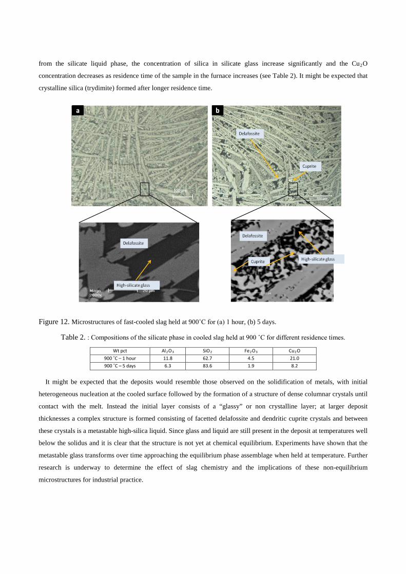
from the silicate liquid phase, the concentration of silica in silicate glass increase significantly and the Cu2O
concentration decreases as residence time of the sample in the furnace increases (see Table 2). It might be expected that
crystalline silica (trydimite) formed after longer residence time.
Figure 12. Microstructures of fast-cooled slag held at 900˚C for (a) 1 hour, (b) 5 days.
Table 2. : Compositions of the silicate phase in cooled slag held at 900 ˚C for different residence times.
Wt pct Al2O3 SiO2 Fe2O3 Cu2O
900 ˚C – 1 hour 11.8 62.7 4.5 21.0
900 ˚C – 5 days 6.3 83.6 1.9 8.2
It might be expected that the deposits would resemble those observed on the solidification of metals, with initial
heterogeneous nucleation at the cooled surface followed by the formation of a structure of dense columnar crystals until
contact with the melt. Instead the initial layer consists of a “glassy” or non crystalline layer; at larger deposit
thicknesses a complex structure is formed consisting of facetted delafossite and dendritic cuprite crystals and between
these crystals is a metastable high-silica liquid. Since glass and liquid are still present in the deposit at temperatures well
below the solidus and it is clear that the structure is not yet at chemical equilibrium. Experiments have shown that the
metastable glass transforms over time approaching the equilibrium phase assemblage when held at temperature. Further
research is underway to determine the effect of slag chemistry and the implications of these non-equilibrium
microstructures for industrial practice.

5. Conclusions
To date, the designs of freeze linings for pyrometallurgical furnaces have been based solely on heat transfer
considerations. There is increasing evidence from the present and previous studies to show, however, that optimum
practice should also take into account the effects of bath chemistry and the kinetics of formation of the deposits. It has
been demonstrated that deposit formation can be studied under laboratory conditions through the use of the “air-cooled
finger” technique. This approach and the experimental design that has been developed enables the mechanisms of freeze
lining formation to be systematically investigated, and the effects of chemically-relevant parameters on the
microstructure, stability, thickness and overall heat transfer of freeze lining in steady-state conditions under well-
characterised thermal and mass transfer conditions to be determined.
The phases found in deposits on the air-cooled substrates, formed from liquid slags in the system“Cu2O”-“Fe2O3”-
SiO2-Al2O3 in equilibrium with copper, are not those expected from equilibrium considerations. The microstructures
present in the freeze lining are shown to vary with deposit thickness and are complex in structure. Further work on
these systems and these interesting phenomena is currently underway, the aim being to provide not only understanding
of the fundamental phenomena taking place in the system but also inform improved design of metallurgical reaction
systems.
Acknowledgements
The authors would like to thank the Australian Research Council Linkage program, Rio Tinto Kennecott Utah
Copper Corp., Xstrata Technology, Xstrata Copper, BHP Billiton Olympic Dam Operation and Outotec Finland Oy for
their financial support.
References
[1] M. Campforts, E. Jak, B. Blanpain and P. Wollants. Freeze-lining formation of a synthetic lead slag: Part I.microstructure formation. Metall.Mater.Trans.B, 2009, 40B, p 619-631.
[2] K. Verscheure, M.V. Camp, B. Blanpain, P. Wollants and P. Hayes. Continuous fuming of zinc-bearing residues: Part I. model development. Metall.Mater.Trans.B, 2007, 38B, p 13-20.
[3] K. Verscheure, M. Campforts, F. Verhaeghe, E. Boydens and M.V. Camp. Water-cooled probe technique for the study of freeze lining formation. Metall.Mater.Trans.B, 2006, 37B, p 929-940.
[4] K. Verscheure, M.V. Camp, B. Blanpain, P. Wollants and P. Hayes. Continuous fuming of zinc-bearing residues: Part II. The submerged-plasma zinc-fuming process. Metall.Mater.Trans.B, 2007, 38B, p 21-33.
[5] J.H. Zietsman and C. Pistorius. Modelling of an ilmenite-smelting DC arc furnace process. Minerals Engineering, 2005, 19(3), p 262- 279.
[6] M. Campforts, E. Jak, B. Blanpain and P. Wollants. Freeze-lining formation of a synthetic lead slag: Part II. thermal history. Metall.Mater.Trans.B, 2009, 40B, p 632-642.
[7] M. Campforts, K. Verscheure, E. Boydens, T.V. Rompaey and B. Blanpain. On the microstructure of a freeze lining of an industrial nonferrous slag. Metall.Mater.Trans.B, 2007, 38B, p 841-851.
[8] A.K. Kyllo and N.B. Gray. Composite furnace module cooling systems in the electric slag cleaning furnace. European Metallurgical Conference, 2005, p 1027-1034.
[9] A. Solheim and L.I.R. Støen. On the composition of solid deposit frozen out from cryolitic melts Light Metals, 1997, p 352-32.
[10] J.Thonstad and S.Rolseth. Equilibrium between bath and side ledge in aluminium cells. Light Metals, 1983, p 415-424
[11] M. Campforts, B. Blanpain and P. Wollants. The Importance of slag engineering in freeze-fining applications. Metall.Mater.Trans.B, 2009, 40B, p 643-655.
[12] M. Campforts, K. Verscheure, E. Boydens, T.V. Rompaey and B. Blanpain. On the mass transport and the crystal growth in a freeze lining of an industrial nonferrous slag. Metall.Mater.Trans.B, 2008, 39B, p 408-417.
[13] T. Hidayat, H.M. Henao, P.C. Hayes and E. Jak. Experimental study of phase equilibria of silicate slag systems. Copper 2010, 2010, p 761-778.
[14] A. Muan and E.F. Osborn, Phase Equilibria Among Oxides in Steelmaking Reading Mass., Addison-Wesley, 1965. [15] FactSage Ver. 6.2. 2010, CRCT-Thermfact Inc & GTT-Technologies: Montreal, Canada.