Intuitive Transcritical CO2 Plant Controller Installation ... Transcritical CO... · Intuitive...
40
!!!"#$%&'#($)*"(&* ` Intuitive Transcritical CO2 Plant Controller Installation & User Guide ,$%&'#($ -./. 0.1.2$*$1/ 3/) 45 6&71%/&1$ 89$1'$: ;<==<12/&1 >1)'%/#<.= ?%/./$: @=.%2&!: A(&/=.1) @BC DEF GH IDDJ5KLDL 4L5 C4C4 A!</(7M&.#) %'NN&#/O#$%&'#($)*"(&* P$(71<(.= A'NN&#/ %.=$%O#$%&'#($)*"(&* A.=$% ?1Q'<#<$% For Products: - PR0710, PR0711, PR0720, PR0721 PR0651-STEP PR0651-STEP OIL
Transcript of Intuitive Transcritical CO2 Plant Controller Installation ... Transcritical CO... · Intuitive...

!!!"#$%&'#($)*"(&*+
`
Intuitive Transcritical CO2 Plant Controller Installation & User Guide
,$%&'#($+-./.+0.1.2$*$1/+3/)++45+6&71%/&1$+89$1'$:+;<==<12/&1+>1)'%/#<.=+?%/./$:+
@=.%2&!:+A(&/=.1)+@BC+DEF+GH++IDDJ5KLDL+4L5+C4C4+ + A!</(7M&.#)++%'NN&#/O#$%&'#($)*"(&*+ P$(71<(.=+A'NN&#/++%.=$%O#$%&'#($)*"(&*++ A.=$%+?1Q'<#<$%+
++
!
For Products: - PR0710, PR0711, PR0720, PR0721
PR0651-STEP PR0651-STEP OIL

Revision 1.0 Page 2 of 40
Warning Please Note The specifications of the product detailed on this Set-Up Guide may change without notice. RDM Ltd. shall not be liable for errors or for incidental or consequential damages, directly and indirectly, in connection with the furnishing, performance or misuse of this product or document.
Ensure that all power is switched off before installing or maintaining this product www.resourcedm.com
Intuitive Transcritical CO2 Plant Controller
Table of Contents:
THE INTUITIVE RANGE ..................................................................................................................................... 4!
Description ......................................................................................................................................................... 4!Configuration ..................................................................................................................................................... 4!Plant Controller Colour Touch Display (PR0615) ........................................................................................... 5!Plant Controller Panel Mount Display (PR0620) ............................................................................................. 6!Top connectors .................................................................................................................................................. 8!Bottom Connectors ........................................................................................................................................... 8!Section of controller showing Universal IO (Inputs and Outputs) ............................................................... 9!Inputs and Outputs: ........................................................................................................................................... 9!Setting up the controller ................................................................................................................................... 9!
Set-up Mode ..................................................................................................................................................... 9!Set-up through front display buttons ................................................................................................................ 9!
Recommended set-up method ....................................................................................................................... 10!Universal IO ................................................................................................................................................... 10!Status Input Type ........................................................................................................................................... 10!rtc. Real time clock (This will automatically synchronise on network systems) ............................................. 11!type. Set/view controller type ......................................................................................................................... 11!Broadcast ....................................................................................................................................................... 11!Set/View Probe Types & Units ....................................................................................................................... 11!Set/View Offset .............................................................................................................................................. 12!
Network Configuration .................................................................................................................................... 12!IP-L ................................................................................................................................................................. 12!IP-r .................................................................................................................................................................. 12!
PArA. Set/view parameters ............................................................................................................................. 13!Parameter Description: ................................................................................................................................... 18!HT/LT Interlock ................................................................................................................................................. 20!Gas Dump ......................................................................................................................................................... 20!Run-Proof ......................................................................................................................................................... 20!Standby Mode .................................................................................................................................................. 21!
Gas Cooler states with pressure rising and falling ......................................................................................... 21!Pack Fault ......................................................................................................................................................... 22!Gas Cooler Valve (HT VALVE) ........................................................................................................................ 22!
Gas Cooler Pressure Setpoint ....................................................................................................................... 22!Gas Cooler Calculated Temperature ............................................................................................................. 22!Extra Refrigeration Capacity .......................................................................................................................... 22!Cooler Interlock .............................................................................................................................................. 22!
Receiver/Separator Bypass Valve (MT Valve) .............................................................................................. 23!Receiver Interlock .......................................................................................................................................... 23!Auxiliary Compressor ..................................................................................................................................... 23!
Gas Cooler Fans Control ................................................................................................................................ 23!Fixed............................................................................................................................................................... 23!Floating........................................................................................................................................................... 23!
Setup via a PC .................................................................................................................................................. 23!Plant Controller home page ........................................................................................................................... 24!Change Configuration (PC) ............................................................................................................................ 25!
Status Inputs: ................................................................................................................................................... 26!Ext Target ......................................................................................................................................................... 27!Section Stages ................................................................................................................................................. 27!Alarm Relay ...................................................................................................................................................... 27!Stage Sizes ....................................................................................................................................................... 27!Operation (Fuzzy) ............................................................................................................................................ 27!Operation (Staged) .......................................................................................................................................... 27!Other operational features .............................................................................................................................. 28!
Invert Relays .................................................................................................................................................. 28!USB Operation ............................................................................................................................................... 28!
Viewing ............................................................................................................................................................. 28!

Revision 1.0 Page 3 of 40
Warning Please Note The specifications of the product detailed on this Set-Up Guide may change without notice. RDM Ltd. shall not be liable for errors or for incidental or consequential damages, directly and indirectly, in connection with the furnishing, performance or misuse of this product or document.
Ensure that all power is switched off before installing or maintaining this product www.resourcedm.com
Intuitive Transcritical CO2 Plant Controller
Inputs and Outputs ......................................................................................................................................... 28!Input and Output Configuration ...................................................................................................................... 28!Plant Controller Board .................................................................................................................................... 28!Stepper Expansion Board .............................................................................................................................. 29!IO Expansion Board (For Oil Monitoring ........................................................................................................ 29!
Input/Output Tables ......................................................................................................................................... 30!Quickview ......................................................................................................................................................... 31!Override ............................................................................................................................................................ 31!Info Button ........................................................................................................................................................ 32!Probe Offsets ................................................................................................................................................... 32!Display Messages ............................................................................................................................................ 32!Network Alarms ............................................................................................................................................... 32!Specification .................................................................................................................................................... 33!
Power requirements: ...................................................................................................................................... 33!Inputs.............................................................................................................................................................. 33!Analogue Outputs .......................................................................................................................................... 33!
Installation: ....................................................................................................................................................... 35!Mounting on to a DIN rail ............................................................................................................................... 35!Clearances: .................................................................................................................................................... 35!
CO2 CIRCUIT DIAGRAM.................................................................................................................................. 36!
CO2 Pressure to Temperature Curve ............................................................................................................ 37!
APPENDIX 1 TYPICAL TRANSDUCER CONNECTION ................................................................................. 38!
PART NUMBERS .............................................................................................................................................. 39!
REVISION HISTORY ......................................................................................................................................... 40!

Revision 1.0 Page 4 of 40
Warning Please Note The specifications of the product detailed on this Set-Up Guide may change without notice. RDM Ltd. shall not be liable for errors or for incidental or consequential damages, directly and indirectly, in connection with the furnishing, performance or misuse of this product or document.
Ensure that all power is switched off before installing or maintaining this product www.resourcedm.com
Intuitive Transcritical CO2 Plant Controller
!"#$%&'()')*#$+,&-#$
From Resource Data Management
This documentation refers to the Intuitive Transcritical CO2 Plant Controller
Description The Intuitive Transcritical CO2 Plant Controller is a versatile controller intended for HT/LT CO2 Pack and Gas Cooler control. Comprising of a Intuitive Plant controller and Plant Expansion board/s. There are 12 relay outputs that are configurable for compressors, loaders, trim compressors or gas dump relays. 12 digital inputs can be assigned for Pack section inputs or general alarms, 2 for receiver liquid level detectors and one to select extra capacity. There are seven (4-20mA or 0-10Vdc) inputs for pressure transducers; 2 for HT and LT control purposes 1 for gas cooler pressure, 1 for Receiver pressure, 1 for liquid level detector and 2 for pressure monitoring. There are 3 probe inputs to measure gas cooler temperature and cooler air on and air off temperatures and 8 temperature probe inputs for temperature monitoring. There are 4 relay outputs that are used for a gas fan output enable, a receiver valve output enable, an Auxiliary Compressor Output enable and a transcritical relay. There are 5 analogue outputs (these can be set to either 0-10V dc or 4-20mA or 0-20mA) 2 to control variable speed drives on HT and LT compressors, 1 each to control variable speed devices on a gas cooler valve(HT VALVE), a gas cooler fan output, auxiliary compressor and a receiver/separator bypass valve (MT VALVE) (Receiver/Separator also has option for Stepper Valve output to drive the Bypass Valve (MT VALVE) instead of Variable speed drive. There are 8 Status Inputs that can be used for Oil Faults. Note : The HT, LT and one of the monitor pressures (input 3 on Plant Controller Board) are also available to be broadcast over the DM network for use by RDM Mercury Switch (PR0018-PHI). The "Fuzzy" based algorithm, will give enhanced control whilst maintaining the starts/hr requirement. The algorithm also reduces the number of input parameters required for control; only a target pressure is needed.
The Intuitive Plant controller has an embedded Ethernet port to allow for connection to a Data Manager system without the need for a communications module. A USB port allows for a direct PC connection. There are two part numbers available: PR0651-STEP and PR0651-STEP OIL. See: Part Numbers PR0651-STEP For HT/LT Pack and Cooler Operation PR0651-STEP OIL For HT/LT Pack, Cooler and Oil operation Configuration The controller has four configuration options: -
Display value Type Control Type 1 Dual Pack with Gas Cooler Fuzzy 2 Dual Pack with Gas Cooler Staged 3 Dual Pack with Gas Cooler and Oil Fuzzy 4 Dual Pack with Gas Cooler and Oil Staged
The controller is delivered pre-configured as a Dual Pack with Gas Cooler Controller (Type 1) See Type Change A PC program is available to pre-configure the Pack controller for downloading into the Plant hardware. Contact RDM for further details. See: Set-up to change the controller type.

Revision 1.0 Page 5 of 40
Warning Please Note The specifications of the product detailed on this Set-Up Guide may change without notice. RDM Ltd. shall not be liable for errors or for incidental or consequential damages, directly and indirectly, in connection with the furnishing, performance or misuse of this product or document.
Ensure that all power is switched off before installing or maintaining this product www.resourcedm.com
Intuitive Transcritical CO2 Plant Controller
Plant Controller Colour Touch Display (PR0615) The Plant Controller Colour Touch Display comes as part of kit (PR0601-IO) and (PR0601-STEP) and is the primary interface for viewing inputs, outputs, parameters and alarm information. This display also allows the user to view the current control state and make changes to parameters. Included in the kits is a Plant Controller Panel Mount Display which is a secondary display and can be used as a backup and for the initial installation. The custom screen, shown below, can be used to show any Input, output or the control state using a selection of graphic interfaces. This allows the user to highlight the key values or processes to quickly and easily view the desired information. The Display has a built in alarm sounder and a status indicator bar. The status indicator bar is blue with no alarms and changes to red when in an alarm condition. When an alarm condition occurs the alarm description is listed on the display, the status bar changes to flashing red and the sounder will be activated. When the accept button is pressed on the display the sounder will be muted and the status indicator bar at the top of the display will become static red. When the alarm condition clears the status indicator bar will return to static blue Individual alarms can also be disabled at the touchscreen display so that specific alarms will not sound or be displayed on the display, in this situation alarms will still be sent to the Data Manager.
Opposite is a typical screen showing a list of Inputs, the touch display allows you to scroll up and down the list by placing your finger on the display and sliding it upward or downward motion.
setting up of display i.e. Parameters, Alarms and what is displayed on Custom page for example Bar Graphs, Gauges and Values.
Revision 1.0 Page 6 of 40
Warning Please Note The specifications of the product detailed on this Set-Up Guide may change without notice. RDM Ltd. shall not be liable for errors or for incidental or consequential damages, directly and indirectly, in connection with the furnishing, performance or misuse of this product or document.
Ensure that all power is switched off before installing or maintaining this product www.resourcedm.com
Intuitive Transcritical CO2 Plant Controller
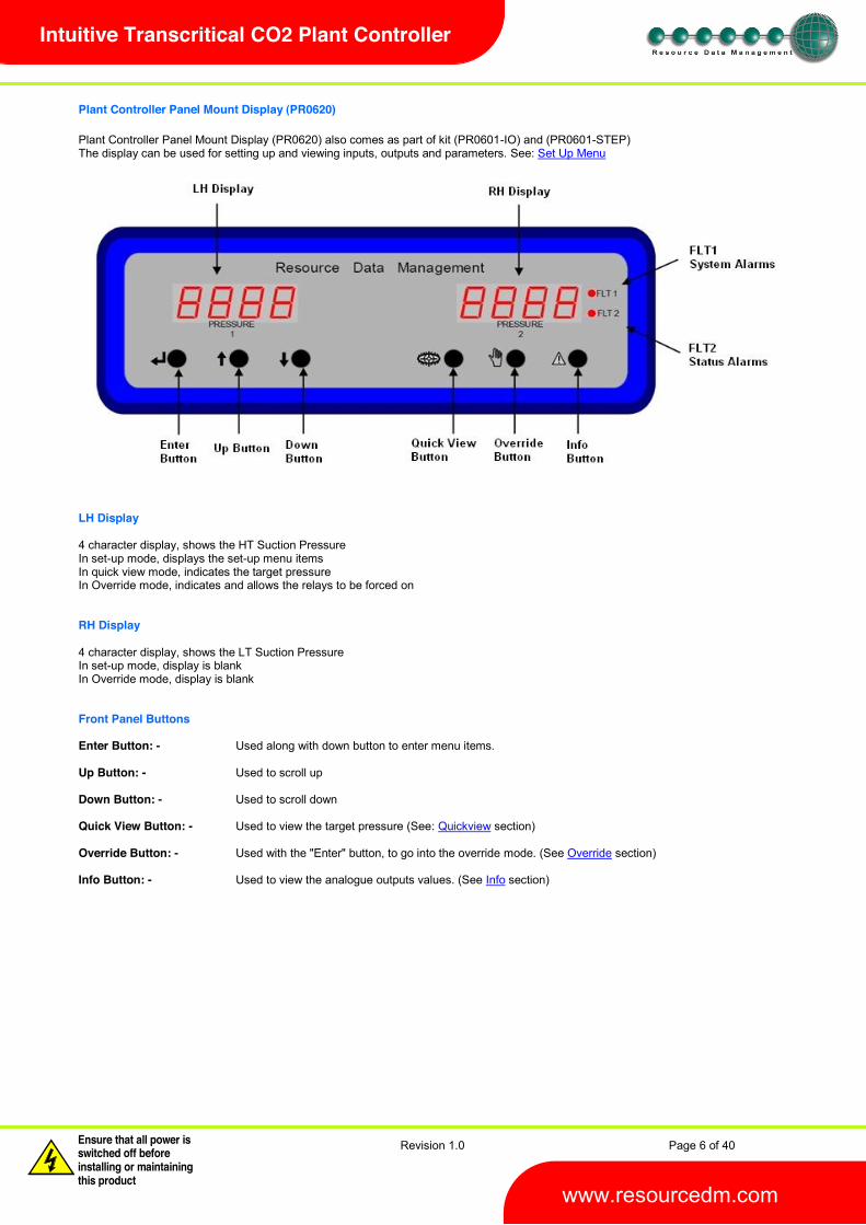
Plant Controller Panel Mount Display (PR0620) Plant Controller Panel Mount Display (PR0620) also comes as part of kit (PR0601-IO) and (PR0601-STEP) The display can be used for setting up and viewing inputs, outputs and parameters. See: Set Up Menu LH Display 4 character display, shows the HT Suction Pressure In set-up mode, displays the set-up menu items In quick view mode, indicates the target pressure In Override mode, indicates and allows the relays to be forced on RH Display 4 character display, shows the LT Suction Pressure In set-up mode, display is blank In Override mode, display is blank Front Panel Buttons Enter Button: - Used along with down button to enter menu items. Up Button: - Used to scroll up Down Button: - Used to scroll down Quick View Button: - Used to view the target pressure (See: Quickview section) Override Button: - Used with the "Enter" button, to go into the override mode. (See Override section) Info Button: - Used to view the analogue outputs values. (See Info section)

Revision 1.0 Page 7 of 40
Warning Please Note The specifications of the product detailed on this Set-Up Guide may change without notice. RDM Ltd. shall not be liable for errors or for incidental or consequential damages, directly and indirectly, in connection with the furnishing, performance or misuse of this product or document.
Ensure that all power is switched off before installing or maintaining this product www.resourcedm.com
Intuitive Transcritical CO2 Plant Controller
Main Controller I/O Connections (PR0650-TCO2) These show the controller without the integral display Top connectors Bottom connectors

Revision 1.0 Page 8 of 40
Warning Please Note The specifications of the product detailed on this Set-Up Guide may change without notice. RDM Ltd. shall not be liable for errors or for incidental or consequential damages, directly and indirectly, in connection with the furnishing, performance or misuse of this product or document.
Ensure that all power is switched off before installing or maintaining this product www.resourcedm.com
Intuitive Transcritical CO2 Plant Controller
Intuitive Stepper Expansion Module (PR0660) Top connectors Bottom Connectors

Revision 1.0 Page 9 of 40
Warning Please Note The specifications of the product detailed on this Set-Up Guide may change without notice. RDM Ltd. shall not be liable for errors or for incidental or consequential damages, directly and indirectly, in connection with the furnishing, performance or misuse of this product or document.
Ensure that all power is switched off before installing or maintaining this product www.resourcedm.com
Intuitive Transcritical CO2 Plant Controller
Universal I/O Inputs and outputs Universal I/O (Inputs) Universal I/O (Outputs) Section of controller showing Universal IO (Inputs and Outputs) Inputs and Outputs:
All Types Description Comments Digital Input 1 - 12 0V return or 24 Vac Note 1 Analogue Input 1 - 8 Probe input Note 2 Universal IO 1 - 8 Analogue input/output See: Universal IO Relay 1 - 12 N/O, N/C and Common Volt Free Status LED Healthy LED When powered up the LED will flash off/on every 0.5
seconds. Note 1: 24 Vac must have the same 24 Vac return as the supply Voltage. If using the Plant controller 24V power supply only the 24Vac signal from the supply is required for the digital input. If using an external 24V power supply to signal a status change then both a common (0V) and status input signal (24V) is required for the appropriate digital input. Note 2: Several probe types are available, See: Probe Type Setting up the controller Set-up access to the controller can be achieved several ways
Through the front mounted buttons on the remote display Direct access by PC via a USB connection Direct access by a PC via an Ethernet Connection Through the RDM Data Manager.
Set-up Mode Set-up through front display buttons To enter set-display. Now press the Enter button again to enter the function menu. IO will be displayed. Scroll up or down to go through the list. Alternatively use either a PC connection for configurations or load a configuration from a memory-stick
Revision 1.0 Page 10 of 40
Warning Please Note The specifications of the product detailed on this Set-Up Guide may change without notice. RDM Ltd. shall not be liable for errors or for incidental or consequential damages, directly and indirectly, in connection with the furnishing, performance or misuse of this product or document.
Ensure that all power is switched off before installing or maintaining this product www.resourcedm.com
Intuitive Transcritical CO2 Plant Controller
Set-up Menu
LH Display LH Display Option Menu Item seen in type: Explained in Paragraph
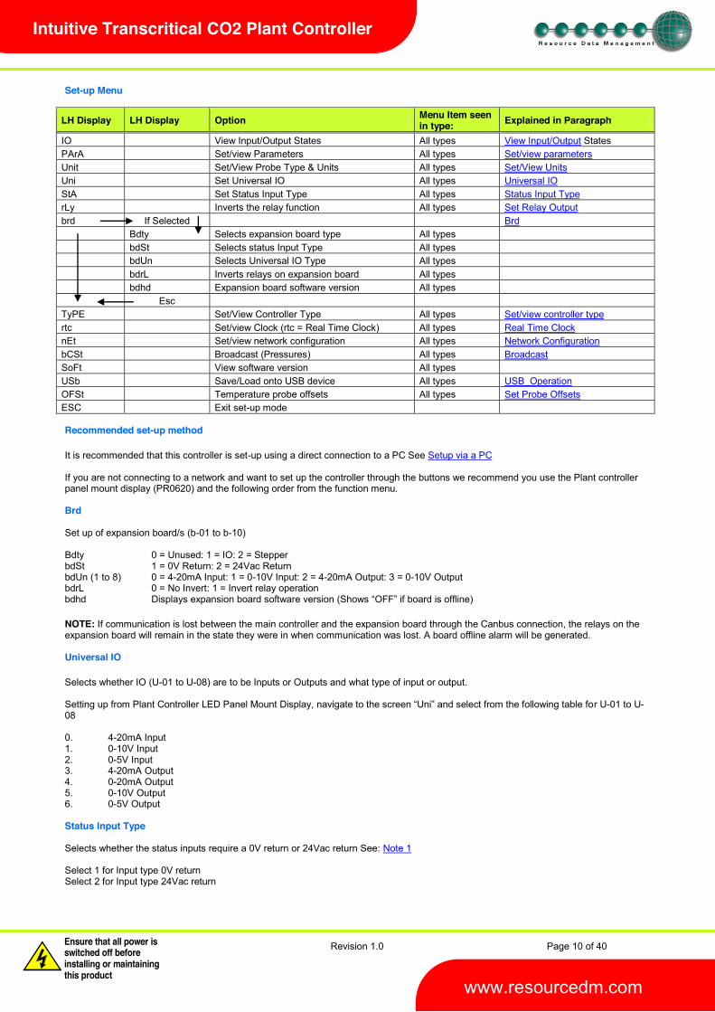
IO View Input/Output States All types View Input/Output States PArA Set/view Parameters All types Set/view parameters Unit Set/View Probe Type & Units All types Set/View Units Uni Set Universal IO All types Universal IO StA Set Status Input Type All types Status Input Type rLy Inverts the relay function All types Set Relay Output brd If Selected Brd Bdty Selects expansion board type All types bdSt Selects status Input Type All types bdUn Selects Universal IO Type All types bdrL Inverts relays on expansion board All types bdhd Expansion board software version All types Esc TyPE Set/View Controller Type All types Set/view controller type rtc Set/view Clock (rtc = Real Time Clock) All types Real Time Clock nEt Set/view network configuration All types Network Configuration bCSt Broadcast (Pressures) All types Broadcast SoFt View software version All types USb Save/Load onto USB device All types USB_Operation OFSt Temperature probe offsets All types Set Probe Offsets ESC Exit set-up mode Recommended set-up method It is recommended that this controller is set-up using a direct connection to a PC See Setup via a PC If you are not connecting to a network and want to set up the controller through the buttons we recommend you use the Plant controller panel mount display (PR0620) and the following order from the function menu. Brd Set up of expansion board/s (b-01 to b-10) Bdty 0 = Unused: 1 = IO: 2 = Stepper bdSt 1 = 0V Return: 2 = 24Vac Return bdUn (1 to 8) 0 = 4-20mA Input: 1 = 0-10V Input: 2 = 4-20mA Output: 3 = 0-10V Output bdrL 0 = No Invert: 1 = Invert relay operation bdhd NOTE: If communication is lost between the main controller and the expansion board through the Canbus connection, the relays on the expansion board will remain in the state they were in when communication was lost. A board offline alarm will be generated. Universal IO Selects whether IO (U-01 to U-08) are to be Inputs or Outputs and what type of input or output.
r U-01 to U-08 0. 4-20mA Input 1. 0-10V Input 2. 0-5V Input 3. 4-20mA Output 4. 0-20mA Output 5. 0-10V Output 6. 0-5V Output Status Input Type Selects whether the status inputs require a 0V return or 24Vac return See: Note 1 Select 1 for Input type 0V return Select 2 for Input type 24Vac return

Revision 1.0 Page 11 of 40
Warning Please Note The specifications of the product detailed on this Set-Up Guide may change without notice. RDM Ltd. shall not be liable for errors or for incidental or consequential damages, directly and indirectly, in connection with the furnishing, performance or misuse of this product or document.
Ensure that all power is switched off before installing or maintaining this product www.resourcedm.com
Intuitive Transcritical CO2 Plant Controller
rtc. Real time clock (This will automatically synchronise on network systems)
1. 2. - 3. Scroll hours up or down (0 23) press enter 4. - 5. Scroll minutes up or down (0 59) press enter 6. Repeat for t-3 (seconds 0 59) 7. Repeat for t-4 (Days up to 31) 8. Repeat for t-5 (months up to 12) 9. Repeat for t-6 (Year up to 99) 10. Use up button to disp
Time clock is now set
type. Set/view controller type
1. From the function menu scroll to "type", press enter 2. Use the up/down buttons to scroll through the type values. (See configuration on page 4) 3. Press enter.
The controller will reset with the selected type now programmed. Type Change NOTE : When changing controller types from one type to another always check the parameters and the controller configuration to ensure they are appropriate for the application selected. Broadcast Allows pressure readings on Variable Inputs on the plant controller to be broadcast over the DM network to be used up by a Mercury Switch to calculate evaporator temperature which is in turn broadcast over the network to be used by any EEV Case Controllers logged on through that Switch to calculate Superheat 0 = Feature Disabled 1 = Feature Enabled See RDM Mercury Switch User Guide (PR0018-PHI) for further information. Set/View Probe Types & Units This operation is only available at the controller display or via a PC connection to the plant controller. It cannot be set remotely via the Data manager front end system. Probe type changes affect all probes. They cannot be set individually to different types. This option allows the user to set the probe types and units. Note: If the units are set to OC, pressure will be displayed in Bar, if units are set to OF, pressure will be displayed in psi.
Unit Number Probe Type Units 0 Probes not used 1 PT1000 OC 2 PT1000 OF 3 NTC2K OC 4 NTC2K OF 5 NTC470R OC 6 NTC470R OF 7 NTC700R OC 8 NTC700R OF 9 NTC3K OC
10 NTC3K OF 11 NTC2K25 OC 12 NTC2K25 OF 13 NTC100K OC 14 NTC100K OF 15 NTC5K OC 16 NTC5K OF 17 NTC6K OC 18 NTC6K OF 19 NTC10K OC 20 NTC10K OF 21 NTC10K (2) OC 22 NTC10K (2) OF
Temperature Probe Range -80 Degree Celsius to +128 Degree Celsius.

Revision 1.0 Page 12 of 40
Warning Please Note The specifications of the product detailed on this Set-Up Guide may change without notice. RDM Ltd. shall not be liable for errors or for incidental or consequential damages, directly and indirectly, in connection with the furnishing, performance or misuse of this product or document.
Ensure that all power is switched off before installing or maintaining this product www.resourcedm.com
Intuitive Transcritical CO2 Plant Controller
Set/View Offset This feature allows the probe display temperature to be offset by the value selected: Each of the 8 probes has an individual offset, see the table below: - C-01 = Probe 1 etc. Note: This can only be set at the plant controller panel mount display and cannot be set remotely by a Data Manager front-end or touch display.
OFSt (Display) Range Step Default C-01 to C-08 ±20O 0.1 0
Network Configuration There are two network connection options
IP- IP-
IP-L allows you to fix an IP address into the controller, which you would use when you are local area network. This would allow the customer to view each controller using Internet Explorer IP-r (normally used mode) allows you to give each controller on the system a unique network ID. This ID is then allocated a dynamic IP address by the system DHCP server (such as the RDM Data Director) IP-L To configure the Plant Controller for IP-L, set all three rotary switches to zero. The unit should then be connected to the network.
1. nEt. From the function menu you can now select nEt - You can now set the address using the table below
Display Option IP-1 IP Address byte 1
IP-2 IP Address byte 2
IP-3 IP Address byte 3
IP-4 IP Address byte 4
nL Network Mask Length
gt-1 Gateway Address byte 1
gt-2 Gateway Address byte 2
gt-3 Gateway Address byte 3
gt-4 Gateway Address byte 4
ESC Exit network menu. N.B. this option must be selected to save any changes made in this menu
IP-r To configure the communication module for IP-r, set the three rotary switches to give each controller a unique identifier (other than 000). The module should then be connected to the controller and the network via the Ethernet port. The Data Manager will use DHCP to allocate the controller an IP address.
From the function menu select nEt - You can now view the address given by the DHCP server
IP1: Shows the first IP address value (10 in the example below) IP2: Shows the second IP address value (1 in the example below) IP3: Shows the third IP address value (2 in the example below) IP4: Shows the forth IP address value (86 in the example below) Example: 10.1.2.86

Revision 1.0 Page 13 of 40
Warning Please Note The specifications of the product detailed on this Set-Up Guide may change without notice. RDM Ltd. shall not be liable for errors or for incidental or consequential damages, directly and indirectly, in connection with the furnishing, performance or misuse of this product or document.
Ensure that all power is switched off before installing or maintaining this product www.resourcedm.com
Intuitive Transcritical CO2 Plant Controller
PArA. Set/view parameters
1. From the function menu scroll to PArA 2. Pressing Enter while PArA is displayed will enter the parameter menu.
The first parameter option will be displayed as P-01. Pressing the Up or Down button will present the other parameter options P-02, P-03 etc. See the parameter list below to find what parameter number corresponds to which actual parameter. Pressing the Enter button will show the current value of the selected parameter. Press Up or Down to modify the value and press Enter again to save the value. The parameter list number will be displayed again. Two other options are present in the parameter menu dFLt and ESC. Selecting ESC will exit the parameter set-up mode. Selecting dFLt will reset all parameters back to the default values for the current controller type.
Dual
Pac
k +
Gas
Coo
ler
(Fuz
zy T
ype
1)
Dual
Pac
k +
Gas
Coo
ler
(Sta
ged
Type
2)
Dual
Pac
k +
Gas
Coo
ler
+ O
il (F
uzzy
Typ
e 3)
Dual
Pac
k +
Gas
Coo
ler
+ O
il (S
tage
d Ty
pe 4
)
No. Parameter Range Step Units Default P-01 Transducer 1 Span * -3.4 - 180 0.1 Bar 60.0 60.0 60.0 60.0 P-02 Transducer 1 Offset -3.4 - 180 0.1 Bar -1.0 -1.0 -1.0 -1.0 P-03 Transducer 2 Span * -3.4 - 180 0.1 Bar 60.0 60.0 60.0 60.0 P-04 Transducer 2 Offset -3.4 - 180 0.1 Bar -1.0 -1.0 -1.0 -1.0 P-05 Transducer 3 Span * -3.4 - 180 0.1 Bar 60.0 60.0 60.0 60.0 P-06 Transducer 3 Offset -3.4 - 180 0.1 Bar -1.0 -1.0 -1.0 -1.0 P-07 Transducer 4 Span * -3.4 - 180 0.1 Bar 160.0 160.0 160.0 160.0 P-08 Transducer 4 Offset -3.4 - 180 0.1 Bar -1.0 -1.0 -1.0 -1.0 P-09 Transducer 5 Span * -3.4 - 180 0.1 Bar 60.0 60.0 60.0 60.0 P-10 Transducer 5 Offset -3.4 - 180 0.1 Bar -1.0 -1.0 -1.0 -1.0 P-11 Transducer 6 Span * -3.4 - 180 0.1 Bar 60.0 60.0 60.0 60.0 P-12 Transducer 6 Offset -3.4 - 180 0.1 Bar -1.0 -1.0 -1.0 -1.0 P-13 Transducer 7 Span * -3.4 - 180 0.1 Bar 60.0 60.0 60.0 60.0 P-14 Transducer 7 Offset -3.4 - 180 0.1 Bar -1.0 -1.0 -1.0 -1.0 P-20 HT Target Pressure -3.4 - 180 0.1 Bar 27.0 27.0 27.0 27.0 P473 HT External Target Pressure -3.4 - 180 0.1 Bar 31.0 31.0 31.0 31.0 P-21 HT Target Pressure Above P-20 -3.4 - 180 0.1 Bar 0.5 0.5 0.5 0.5 P-22 HT Target Pressure Below P-20 -3.4 - 180 0.1 Bar 0.5 0.5 0.5 0.5 P-23
Fuzzy HT Starts/Hour 0 - 60 1 - 10 10
P-23 Staged
HT Number of Stages 0 -12 1 - 0 0
P-24 Fuzzy
HT Run Smallest ** 0 = Off, 1 = On 1 - 0 0
P-24 Staged
HT Stage-on Delay 00:00 60:00 00:01 mins/sec 00:10 00:10
P-25 HT Stage-off Delay 00:00 99:00 00:01 mins/sec 00:10 00:10 P-26 HT Inverter 0 = Off, 1 = On 1 - 0 0 0 0 P444 HT INV Minimum 0 - 100 1 % 0 0 0 0 P446 HT INV Maximum 0 - 100 1 % 100 100 100 100 P490 HT Gas Dump 0 = Off, 1 = On 1 - 0 0 0 0 P492 HT Gas Diff -3.4 - 180 0.1 Bar 0.5 0.5 0.5 0.5 P470 HT Always Run last 0 = Off, 1 = On 1 - 0 0 0 0 P-27 HT Response On Speed 1 - 60 1 - 5 5 5 5 P-28 HT Response Off Speed 1 - 60 1 - 5 5 5 5 P-29 HT Optimise Limit -3.4 - 180 0.1 Bar 2.0 2.0 2.0 2.0 P-30 HT Alarm Delay 00:00 99:00 01:00 mins/sec 05:00 05:00 05:00 05:00 P-31 HT HP Alarm -3.4 - 180 0.1 Bar 38.0 38.0 38.0 38.0 P-32 HT LP Alarm -3.4 - 180 0.1 Bar 24.0 24.0 24.0 24.0 P-33 HT LP Shut-down -3.4 - 180 0.1 Bar 21.0 21.0 21.0 21.0
Revision 1.0 Page 14 of 40
Warning Please Note The specifications of the product detailed on this Set-Up Guide may change without notice. RDM Ltd. shall not be liable for errors or for incidental or consequential damages, directly and indirectly, in connection with the furnishing, performance or misuse of this product or document.
Ensure that all power is switched off before installing or maintaining this product www.resourcedm.com
Intuitive Transcritical CO2 Plant Controller
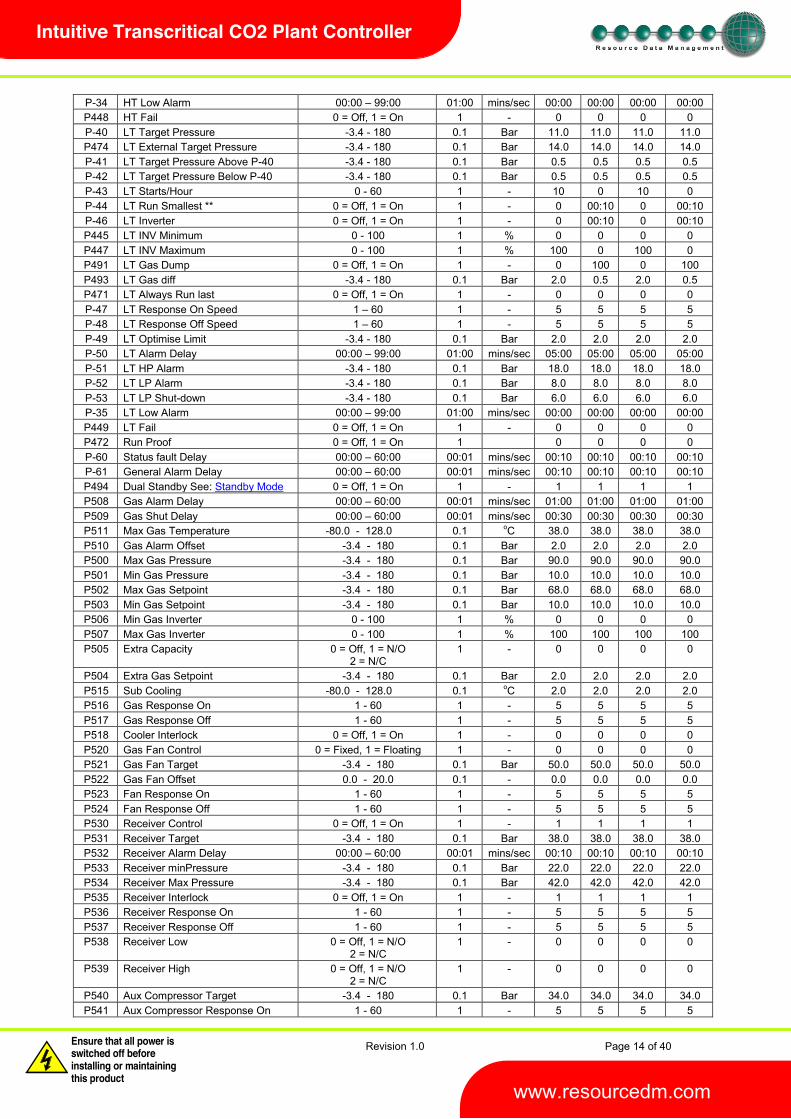
P-34 HT Low Alarm 00:00 99:00 01:00 mins/sec 00:00 00:00 00:00 00:00 P448 HT Fail 0 = Off, 1 = On 1 - 0 0 0 0 P-40 LT Target Pressure -3.4 - 180 0.1 Bar 11.0 11.0 11.0 11.0 P474 LT External Target Pressure -3.4 - 180 0.1 Bar 14.0 14.0 14.0 14.0 P-41 LT Target Pressure Above P-40 -3.4 - 180 0.1 Bar 0.5 0.5 0.5 0.5 P-42 LT Target Pressure Below P-40 -3.4 - 180 0.1 Bar 0.5 0.5 0.5 0.5 P-43 LT Starts/Hour 0 - 60 1 - 10 0 10 0 P-44 LT Run Smallest ** 0 = Off, 1 = On 1 - 0 00:10 0 00:10 P-46 LT Inverter 0 = Off, 1 = On 1 - 0 00:10 0 00:10 P445 LT INV Minimum 0 - 100 1 % 0 0 0 0 P447 LT INV Maximum 0 - 100 1 % 100 0 100 0 P491 LT Gas Dump 0 = Off, 1 = On 1 - 0 100 0 100 P493 LT Gas diff -3.4 - 180 0.1 Bar 2.0 0.5 2.0 0.5 P471 LT Always Run last 0 = Off, 1 = On 1 - 0 0 0 0 P-47 LT Response On Speed 1 60 1 - 5 5 5 5 P-48 LT Response Off Speed 1 60 1 - 5 5 5 5 P-49 LT Optimise Limit -3.4 - 180 0.1 Bar 2.0 2.0 2.0 2.0 P-50 LT Alarm Delay 00:00 99:00 01:00 mins/sec 05:00 05:00 05:00 05:00 P-51 LT HP Alarm -3.4 - 180 0.1 Bar 18.0 18.0 18.0 18.0 P-52 LT LP Alarm -3.4 - 180 0.1 Bar 8.0 8.0 8.0 8.0 P-53 LT LP Shut-down -3.4 - 180 0.1 Bar 6.0 6.0 6.0 6.0 P-35 LT Low Alarm 00:00 99:00 01:00 mins/sec 00:00 00:00 00:00 00:00 P449 LT Fail 0 = Off, 1 = On 1 - 0 0 0 0 P472 Run Proof 0 = Off, 1 = On 1 0 0 0 0 P-60 Status fault Delay 00:00 60:00 00:01 mins/sec 00:10 00:10 00:10 00:10 P-61 General Alarm Delay 00:00 60:00 00:01 mins/sec 00:10 00:10 00:10 00:10 P494 Dual Standby See: Standby Mode 0 = Off, 1 = On 1 - 1 1 1 1 P508 Gas Alarm Delay 00:00 60:00 00:01 mins/sec 01:00 01:00 01:00 01:00 P509 Gas Shut Delay 00:00 60:00 00:01 mins/sec 00:30 00:30 00:30 00:30 P511 Max Gas Temperature -80.0 - 128.0 0.1 oC 38.0 38.0 38.0 38.0 P510 Gas Alarm Offset -3.4 - 180 0.1 Bar 2.0 2.0 2.0 2.0 P500 Max Gas Pressure -3.4 - 180 0.1 Bar 90.0 90.0 90.0 90.0 P501 Min Gas Pressure -3.4 - 180 0.1 Bar 10.0 10.0 10.0 10.0 P502 Max Gas Setpoint -3.4 - 180 0.1 Bar 68.0 68.0 68.0 68.0 P503 Min Gas Setpoint -3.4 - 180 0.1 Bar 10.0 10.0 10.0 10.0 P506 Min Gas Inverter 0 - 100 1 % 0 0 0 0 P507 Max Gas Inverter 0 - 100 1 % 100 100 100 100 P505 Extra Capacity 0 = Off, 1 = N/O
2 = N/C 1 - 0 0 0 0
P504 Extra Gas Setpoint -3.4 - 180 0.1 Bar 2.0 2.0 2.0 2.0 P515 Sub Cooling -80.0 - 128.0 0.1 oC 2.0 2.0 2.0 2.0 P516 Gas Response On 1 - 60 1 - 5 5 5 5 P517 Gas Response Off 1 - 60 1 - 5 5 5 5 P518 Cooler Interlock 0 = Off, 1 = On 1 - 0 0 0 0 P520 Gas Fan Control 0 = Fixed, 1 = Floating 1 - 0 0 0 0 P521 Gas Fan Target -3.4 - 180 0.1 Bar 50.0 50.0 50.0 50.0 P522 Gas Fan Offset 0.0 - 20.0 0.1 - 0.0 0.0 0.0 0.0 P523 Fan Response On 1 - 60 1 - 5 5 5 5 P524 Fan Response Off 1 - 60 1 - 5 5 5 5 P530 Receiver Control 0 = Off, 1 = On 1 - 1 1 1 1 P531 Receiver Target -3.4 - 180 0.1 Bar 38.0 38.0 38.0 38.0 P532 Receiver Alarm Delay 00:00 60:00 00:01 mins/sec 00:10 00:10 00:10 00:10 P533 Receiver minPressure -3.4 - 180 0.1 Bar 22.0 22.0 22.0 22.0 P534 Receiver Max Pressure -3.4 - 180 0.1 Bar 42.0 42.0 42.0 42.0 P535 Receiver Interlock 0 = Off, 1 = On 1 - 1 1 1 1 P536 Receiver Response On 1 - 60 1 - 5 5 5 5 P537 Receiver Response Off 1 - 60 1 - 5 5 5 5 P538 Receiver Low 0 = Off, 1 = N/O
2 = N/C 1 - 0 0 0 0
P539 Receiver High 0 = Off, 1 = N/O 2 = N/C
1 - 0 0 0 0
P540 Aux Compressor Target -3.4 - 180 0.1 Bar 34.0 34.0 34.0 34.0 P541 Aux Compressor Response On 1 - 60 1 - 5 5 5 5

Revision 1.0 Page 15 of 40
Warning Please Note The specifications of the product detailed on this Set-Up Guide may change without notice. RDM Ltd. shall not be liable for errors or for incidental or consequential damages, directly and indirectly, in connection with the furnishing, performance or misuse of this product or document.
Ensure that all power is switched off before installing or maintaining this product www.resourcedm.com
Intuitive Transcritical CO2 Plant Controller
P542 Aux Compressor Response Off 1 - 60 1 - 5 5 5 5 P480 Liquid Level 0 = Off, 1 = On 1 - 0 0 0 0 P481 High Liquid Level 0 - 100 1 % 80 80 80 80 P482 Low Liquid Level 0 - 100 1 % 20 20 20 20 P483 Liquid Level Alarm Delay 00:00 99:00 01:00 mins:sec 05:00 05:00 05:00 05:00 P600
P608
Oil 1 Enable Oil 8 Enable
0 = Off 1 = N/O 2 = N/C
1 - 0 0
P-80
P-91
Status Fault 1 Status Fault 12
(0) Unused (1) Comp N/O (2) Comp N/C (5) Gen N/O (6) Gen N/C (7) Standby 1 N/O (8) Standby 1 N/C (9) Standby 2 N/O (10) Standby 2 N/C (11) Run 1 N/O (12) Run 1 N/C (13) Run 2 N/O (14) Run 2 N/C
1 - 0
0
0
0
P100 Fuzzy
P111
HT Stage 1 HT Stage 12
(0) None, (1) Unused, (2) Compressor, (3) Loader, (5) Inverter (6) Trim (7) Comp Run
1 - 0 0
P120 Fuzzy
P131
HT Stage 1 Size HT Stage 12 Size
0.0 60.0 0.1 - 0.0 0.0
P140 Fuzzy
P151
LT Stage 1 LT Stage 12
(0) None, (1) Unused, (2) Compressor, (3) Loader, (5) Inverter (6) Trim (7) Comp Run
1 - 0 0
P160 Fuzzy
P171
LT Stage 1 Size LT Stage 12 Size
0.0 60.0 0.1 - 0.0
0.0
P100 Staged
P111
HT Stage 1 Relay 1 HT Stage 1 Relay 12
0 = off 1 = on
1 - 0 0
P112 Staged
P123
HT Stage 2 Relay 1 HT Stage 2 Relay 12
0 = off 1 = on
1 0 0
P124 Staged
P135
HT Stage 3 Relay 1 HT Stage 3 Relay 12
0 = off 1 = on
1 0 0
Revision 1.0 Page 16 of 40
Warning Please Note The specifications of the product detailed on this Set-Up Guide may change without notice. RDM Ltd. shall not be liable for errors or for incidental or consequential damages, directly and indirectly, in connection with the furnishing, performance or misuse of this product or document.
Ensure that all power is switched off before installing or maintaining this product www.resourcedm.com
Intuitive Transcritical CO2 Plant Controller
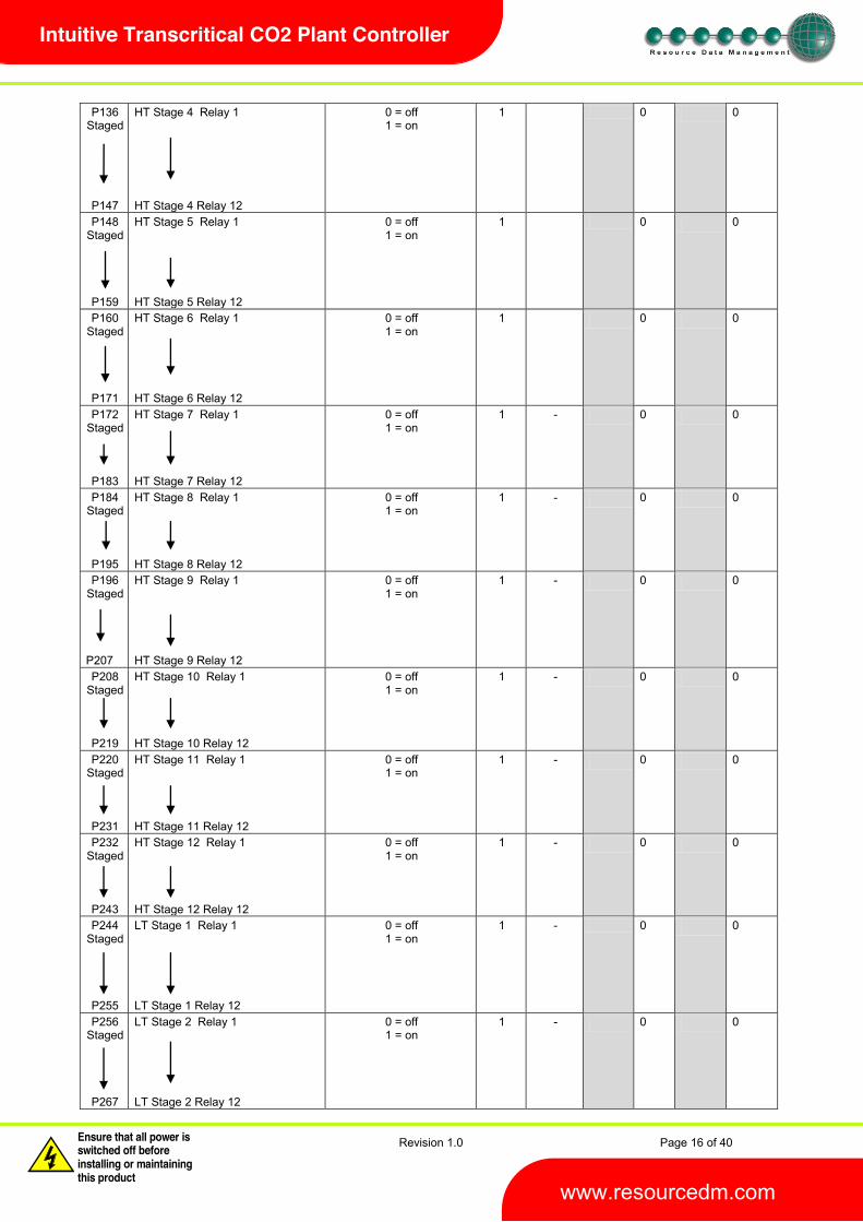
P136 Staged
P147
HT Stage 4 Relay 1 HT Stage 4 Relay 12
0 = off 1 = on
1 0 0
P148 Staged
P159
HT Stage 5 Relay 1 HT Stage 5 Relay 12
0 = off 1 = on
1 0 0
P160 Staged
P171
HT Stage 6 Relay 1 HT Stage 6 Relay 12
0 = off 1 = on
1 0 0
P172 Staged
P183
HT Stage 7 Relay 1 HT Stage 7 Relay 12
0 = off 1 = on
1 - 0 0
P184 Staged
P195
HT Stage 8 Relay 1 HT Stage 8 Relay 12
0 = off 1 = on
1 - 0 0
P196 Staged
P207
HT Stage 9 Relay 1 HT Stage 9 Relay 12
0 = off 1 = on
1 - 0 0
P208 Staged
P219
HT Stage 10 Relay 1 HT Stage 10 Relay 12
0 = off 1 = on
1 - 0 0
P220 Staged
P231
HT Stage 11 Relay 1 HT Stage 11 Relay 12
0 = off 1 = on
1 - 0 0
P232 Staged
P243
HT Stage 12 Relay 1 HT Stage 12 Relay 12
0 = off 1 = on
1 - 0 0
P244 Staged
P255
LT Stage 1 Relay 1 LT Stage 1 Relay 12
0 = off 1 = on
1 - 0 0
P256 Staged
P267
LT Stage 2 Relay 1 LT Stage 2 Relay 12
0 = off 1 = on
1 - 0 0

Revision 1.0 Page 17 of 40
Warning Please Note The specifications of the product detailed on this Set-Up Guide may change without notice. RDM Ltd. shall not be liable for errors or for incidental or consequential damages, directly and indirectly, in connection with the furnishing, performance or misuse of this product or document.
Ensure that all power is switched off before installing or maintaining this product www.resourcedm.com
Intuitive Transcritical CO2 Plant Controller
P268 Staged
P279
LT Stage 3 Relay 1 LT Stage 3 Relay 12
0 = off 1 = on
1 - 0 0
P280 Staged
P291
LT Stage 4 Relay 1 LT Stage 4 Relay 12
0 = off 1 = on
1 - 0 0
P292 Staged
P303
LT Stage 5 Relay 1 LT Stage 5 Relay 12
0 = off 1 = on
1 - 0 0
P-304 Staged
P315
LT Stage 6 Relay 1 LT Stage 6 Relay 12
0 = off 1 = on
1 - 0 0
P316 Staged
P327
LT Stage 7 Relay 1 LT Stage 7 Relay 12
0 = off 1 = on
1 - 0 0
P328 Staged
P339
LT Stage 8 Relay 1 LT Stage 8 Relay 12
0 = off 1 = on
1 - 0 0
P340 Staged
P351
LT Stage 9 Relay 1 LT Stage 9 Relay 12
0 = off 1 = on
1 - 0 0
P352 Staged
P363
LT Stage 10 Relay 1 LT Stage 10 Relay 12
0 = off 1 = on
1 - 0 0
P364 Staged
P375
LT Stage 11 Relay 1 LT Stage 11 Relay 12
0 = off 1 = on
1 - 0 0
P376 Staged
P387
LT Stage 12 Relay 1 LT Stage 12 Relay 12
0 = off 1 = on
1 - 0 0
dFLt Restore Default Settings (Front panel Only)
* Span and Offset allows for the full range of the transducer to be used by the controller. Span is the full range of the transducer Offset is the value below zero.

Revision 1.0 Page 18 of 40
Warning Please Note The specifications of the product detailed on this Set-Up Guide may change without notice. RDM Ltd. shall not be liable for errors or for incidental or consequential damages, directly and indirectly, in connection with the furnishing, performance or misuse of this product or document.
Ensure that all power is switched off before installing or maintaining this product www.resourcedm.com
Intuitive Transcritical CO2 Plant Controller
Note. The controller uses absolute pressure; if gauge pressure is required, add +1 Bar to the offset value. Example Transducer : -1 bar to 59 bar Span would be 60 bar Offset would be -1 bar Transducer would read -1 Bar to 59 Bar **Run smallest = on: - When all compressors are off (because the target pressure has been satisfied) the controller, when the pressure rises, will always turn on the smallest compressor after the variable output has reached 100%. If the ASC timer is running for the smallest compressor, the controller will NOT bring on any other available compressors, the variable output will remain at 100% and the controller will wait until the ASC timer has elapsed and then turn on the smallest. Please note that this is true for any pressure condition. Parameter Description:
Number Parameter Description P-01/03/05/ 07/09/11/13
Transducer 1/2/3/4/5/6/7 Span Range of the transducers
P-02/04/06/ 08/10/12/14
Transducer 1/2/3/4/5/6/7 Offset Transducer value below zero.
P-20/40 Target Pressure Pressure target, control will try to maintain this pressure P-20 = HT Target : P-40 = LT Target See : HT/LT Interlock
P473/474 External Target Pressure Pressure target when Sect1 Run/Sect2 Run is off. Control will try to maintain this pressure until Sect1 Run/Sect2 Run is on. At this point P-20/40 used. Please see Status Inputs
P-21/41 Target Pressure Above P-20/40 Set- - P-22/42 Target Pressure Below P-20/40 Set-po - P-23/43Stg Number of Stages Number of stages in the system P-23/43Fzy Starts per hour Limits a compressor to this many starts per hour P-24/44Fzy Run smallest See explanation under the parameter tables for this parameter Run Smallest P-24/44Stg Stage-on Delay Delay time between stages on (Staged types only) P-25/45Stg Stage-off Delay Delay time between stages off (Staged types only) P-26/46 Inverter Enables the inverter analogue output and associated relay. P444/445 Inverter Min The minimum percentage the inverter will operate to P446/447 Inverter Max The maximum percentage the inverter will operate to P490/491 HT/LT Gas Dump Enables Gas Dump feature. P492/493 HT/LT Gas Diff Diff below the set point that the Gas Dump valve is opened.
See Gas Dump P470/471 Always run last Keeps the last stage running except for a Low Shutdown condition. If the last
stage is an inverter, the inverter enable will stay energised, but the inverter analogue output may well decrease to 0% if pressure is below the set-point.
P-27/47 Response On Speed Allows the user to speed up/slow down the stage on speed (Option: - 1 to 60 with 60 being fastest response) Note: This parameter applies to the inverter output only when using any of the Staged types.
P-28/48 Response Off Speed Allows the user to speed up/slow down the stage off speed (Option: - 1 to 60 with 60 being fastest response) Note: This parameter applies to the inverter output only when using any of the Staged types.
P-29/49 Optimise Limit This is an offset that is added to the target pressure when using the Data Manager Energy feature Pack Optimisation. For example if target pressure is 2.1 Bar and Optimise Limit set to 0.5 Bar. The remote optimise command will only be able to optimise the current suction setpoint up to a maximum of 2.6 Bar
P-30/50 Alarm Delay Delay before HP and LP alarms are signalled P-31/51 HP Alarm HP alarm set-point P-32/52 LP Alarm LP alarm set-point, stage off when reached P-33/53 LP Shut-down LP shut-down set-point, all stages go off when this is reached P-34/35 Low Alarm Delay applied before LP Shutdown alarm is generated. Note as soon as the
LP Shutdown setpoint is reached any Compressor stages, for the associated section, still operating will go off immediately and does not wait for the LP Shutdown alarm to be generated.
P448/449 HT / LT Fail The following will occur in the event of pressure transducer fault on HT or LT : If set to On then all Compressors will turn On in the event of a transducer failure. If set to Off then all Compressors will turn Off in the event of a transducer failure.
P472 Run Proof See section Run-Proof

Revision 1.0 Page 19 of 40
Warning Please Note The specifications of the product detailed on this Set-Up Guide may change without notice. RDM Ltd. shall not be liable for errors or for incidental or consequential damages, directly and indirectly, in connection with the furnishing, performance or misuse of this product or document.
Ensure that all power is switched off before installing or maintaining this product www.resourcedm.com
Intuitive Transcritical CO2 Plant Controller
P-60 Status fault Delay Time delay before status faults are activated P-61 General Alarm Delay Time delay before general faults are activated P494 Dual Standby Used to place two sections into Standby from one Standby status input. (Note
ust be utilised when using this feature) See Note Standby Mode
P508 Gas Alarm Delay Delay applied before Gas Cooler OT/Gas Cooler LP Open/Gas Cooler HP Open alarms are generated
P509 Gas Shut Delay Delay applied before Gas Cooler LP Shutdown/Gas Cooler HP Shutdown alarms are generated
P511 Max Gas Temperature Set point at which Gas Cooler OT alarm is generated, after delay P508 P510 Gas Alarm Offset Offset below Min Gas Pressure P501 that Gas Cooler LP Shutdown alarm is
generated P500 Max Gas Pressure Set point at which Gas Cooler HP Open alarm is generated after delay P508 P501 Min Gas Pressure Set point at which Gas Cooler LP Open alarm is generated after delay P508 P502 Max Gas Setpoint Upper limit of the calculated Gas cooler Set point P503 Min Gas Setpoint Lower limit of the calculated Gas cooler Set point P506 Min Gas Inverter Minimum value that the Gas Cooler Output will go to P507 Max Gas Inverter Maximum value that the Gas Cooler Output will go to P505 Extra Capacity Enables the Cooler Set Point to be raised by amount P504
See : Extra Refrigeration Capacity P504 Extra Gas Setpoint Amount Gas Cooler Set Point is raised by if P505 is enabled P515 Subcooling The amount of subcooling trying to be maintained
P516 Gas Response On Allows the user to speed up/slow down the Gas Cooler output (Option: - 1 to
60 with 60 being fastest response) P517 Gas Response Off Allows the user to speed up/slow down the Gas Cooler output (Option: - 1 to
60 with 60 being fastest response) P518 Cooler Interlock Enables interlock between Pack and Gas Cooler Output
See : Cooler Interlock P520 Gas Fan Control Selects between Fixed or Floating
Fixed uses the set point parameter P521 as its target Floating uses the Gas Cooler Temperature Probe converted to a pressure as the set-point See : Floating
P521 Gas Fan Target elected at P520 P522 Gas Fan Offset Offset added to the value of Gas Cooler Temperature used to calculate the
P523 Fan Response On Allows the user to speed up/slow down the Gas Fans (Option: - 1 to 60 with
60 being fastest response) P524 Fan Response Off Allows the user to speed up/slow down the Gas Fans (Option: - 1 to 60 with
60 being fastest response) P530 Receiver Control Enables/Disables the Receiver Bypass Valve (MT VALVE) operation P531 Receiver Target Set Point at which the Receiver Bypass Valve (MT VALVE) will open and
close (Fixed 0.5 Bar diff above and below with dead band) P532 Receiver Alarm Delay Delay applied before the Receiver Low or High Pressure alarm is generated. P533 Receiver minPressure Setting at which Receiver Low Pressure alarm is generated P534 Receiver Max Pressure Setting at which Receiver High Pressure alarm is generated P535 Receiver Interlock If enabled :
If Receiver Pressure drops below Receiver Minimum Pressure set point Gas Cooler Output Valve (HT VALVE) opens to 100%
P536 Receiver Response On Allows the user to speed up/slow down the Receiver Bypass Valve (MT VALVE) (Option: - 1 to 60 with 60 being fastest response)
P537 Receiver Response Off Allows the user to speed up/slow down the Receiver Bypass Valve (MT VALVE) (Option: - 1 to 60 with 60 being fastest response)
P538 Receiver Low Enables/Disables Receiver Low Level Detector P539 Receiver High Enables/Disables Receiver High Level Detector P540 Aux Compressor Target Pressure at which the Auxiliary Compressor will turn on
See : Auxiliary Compressor P541 Aux Compressor Response On Allows the user to speed up/slow down the Auxiliary Compressor
(Option: - 1 to 60 with 60 being fastest response) P542 Aux Compressor Response Off Allows the user to speed up/slow down the Auxiliary Compressor
(Option: - 1 to 60 with 60 being fastest response) P480 Liquid Level Enable for Liquid Level feature
See Note : Liquid Level P481/482 Liquid Level Alarm Settings at which High and Low Liquid Level alarms are generated P483 Liquid Level Alarm Delay Delay applied before the Low or High liquid alarm is generated.

Revision 1.0 Page 20 of 40
Warning Please Note The specifications of the product detailed on this Set-Up Guide may change without notice. RDM Ltd. shall not be liable for errors or for incidental or consequential damages, directly and indirectly, in connection with the furnishing, performance or misuse of this product or document.
Ensure that all power is switched off before installing or maintaining this product www.resourcedm.com
Intuitive Transcritical CO2 Plant Controller
P600 P607
Oil 1 Enable Oil 8 Enable
Used to enable Oil Fault Inputs N/C or N/O (On second expansion board)
P-80
P-91
Status Fault 1 Status Fault 12
Used to select the type of input required See : Status Inputs
P100/140 Fuzzy
P111/151
Stage 1 Stage 12
Select the output device for this stage See : Section Stages
P120/160 Fuzzy
P131/171
Stage 1 Size Stage 12 Size
Sets the relative size for each compressor
P100 Parameters for Staged type P387
Stage 1 Relay 1 to 12 Stage 12 Relay 1 to 12
Maps compressor relays to stages
HT/LT Interlock The LT Pack cannot run unless there is an HT Compressor running or HT Variable Speed Drive enabled and at some percentage open. Therefore if the last HT compressor goes off due to HT pressure being maintained, then any LT compressors running at that time will go off with the last HT compressor or when the HT Variable speed drive goes to 0% HT Pack Fail If the HT Pack Transducer fails. Both Hshut down. Gas Dump HT/LT Gas Dump Enable (P-490/491). In Fuzzy pack control the Gas dump relay will come on when the HT/LT Suction Pressure drops below the Set Point (P-20/40) minus the Gas Diff (P-492/493) and all but the last compressor has turned off. When an Inverter output is configured using Fuzzy pack control the Gas dump relay will come on only when the Inverter is active, i.e. above 0% and all other Compressors configured in that section are off. With Staged pack control the Gas Dump relay will come on only when last compressor is running. The Gas dump relay will go off again when: - The pressure rises above the Set Point (P-20/40) Or When the last stage compressor goes off, or Inverter Enable is turned off. Run-Proof
he status inputs, using either Compressor Normally Closed or Compressor Normally Open, that correspond with each relay output. When the relay
go off and be taken out of the control strategy until the run proof has been reset. The run-proof feature uses the status fault delay (P-60) and all run proof signals must be returned within this delay period. Run proofs are used with compressor (Comp) stages only. This feature can be used in both Fuzzy and Staged applications. To reset the run proof for any stage, after maintenance, and return a compressor back into the control strategy use the menu item Override. The override option is used to manually turn on the compressor output. If the proof signal is returned within the allotted time
f and remain out of the control strategy.

Revision 1.0 Page 21 of 40
Warning Please Note The specifications of the product detailed on this Set-Up Guide may change without notice. RDM Ltd. shall not be liable for errors or for incidental or consequential damages, directly and indirectly, in connection with the furnishing, performance or misuse of this product or document.
Ensure that all power is switched off before installing or maintaining this product www.resourcedm.com
Intuitive Transcritical CO2 Plant Controller
Alternatively the alarm can be cleared remotely by changing parameter P472 from 1 to 0 (On to Off). This clears all run proof alarms on all compressors which are currently out of the control logic due to run proof feature. Now change P472 from 0 to 1 (Off to On). The compressor(s) will then be available for selection by the control logic. If the compressor is selected by the control strategy and the run proof signal is then not returned within the allotted time delay then it will fail and will be removed from the control logic again. Standby Mode Once in standby all configured stages are turned off and a standby alarm is generated for the given section. The delay applied before a section enters standby is determined by the General Alarm Delay (P-61). Once this delay expires the controller enters standby and a standby alarm is also generated for the relevant section. HT and LT can be placed into standby independently from two separate status inputs or both sections can be placed into standby at the same time from a single status input. P494 determines the Standby configuration. P494 set to 1 = On Controller uses one status input to place both HT and LT into standby. Parameters P-80 to P-91 (Option 7 Std 1 N/O or Option 8 Std 1 N/C) are used to place both Ht and LT into standby from a single status input P494 set 0 = Off Controller uses two independent status inputs to place HT and LT into standby independently. Controller uses P-80 to P-91 (Option 7 Std 1 N/O or 8 Std 1 N/C) to put HT into standby. Controller uses P-80 to P-91 (Option 9 Std 2 N/O or 10 Std 2 N/C) to put LT into standby Liquid Level Liquid Level Detector uses 4-20mA Universal Input 3 on the Plant controller Expansion Board. Where 4mA will give a reading of 0% and 20mA will give a reading of 100%. The Span and Offset parameters for Transducer input 3 do not require adjustment and can be left at
- -481) can be generated. The alarm has a settable delay. Gas Cooler states with pressure rising and falling
High HP Shutdown : Gas cooler Pressure above 115 Bar (Fixed setting)
Supercritical : Gas Cooler Pressure above P500 (Maximum Gas Pressure) (110 Bar)
Transcritical : Gas Cooler Pressure above 73 Bar (Fixed setting) Subcritical : Gas Cooler Pressure Normal (Uses P521 or floating to control fans)
Triple : Gas Cooler Pressure below P501 (Minimum Gas Pressure) (15 Bar)
Low LP Shutdown : Gas Cooler Pressure below 10 Bar (Fixed setting)
Shutdown (HP) As the
Gas Cooler Output Valve (HT VALVE) will close. Gas Cooler Fans will go Off. Transcritical Relay will be On
Note: Once normal pressure has been maintained the controller needs a power reset to regain control. Supercritical As the Gas Cooler Pressure rises above Max Gas Press (P500) for Gas Alarm Delay (P508)
HT and LT Packs will operate as normal. Gas Cooler output (HT VALVE) will be Open. Gas Cooler Fan will be On. Transcritical Relay will be On
arm will be generated. Receiver Output and Aux Comp operate as normal Transcritical If the Gas Cooler Pressure goes above 73 Bar The Transcritical Relay will come on.
HT and LT Packs and Gas Cooler Fans operate as normal Gas Cooler output (HT VALVE) will be Open. Gas Cooler Fan will be On. Receiver Output and Aux Comp operate as normal

Revision 1.0 Page 22 of 40
Warning Please Note The specifications of the product detailed on this Set-Up Guide may change without notice. RDM Ltd. shall not be liable for errors or for incidental or consequential damages, directly and indirectly, in connection with the furnishing, performance or misuse of this product or document.
Ensure that all power is switched off before installing or maintaining this product www.resourcedm.com
Intuitive Transcritical CO2 Plant Controller
Subcritical As the Gas Cooler pressure (Which gives the Gas cooler Calculated Temperature) is between the parameter Min Gas Press setting P501 and 73 Bar. The Transcritical Relay will be Off.
HT and LT Packs and Gas Cooler Fans operate as normal Packs, with compressors going on and off with suction pressures and Gas Cooler Fan going On and Off with Gas Cooler pressure going above and below Gas Fan SP (P521 Fixed) or (Calculated from Gas Cooler Temp. Floating). Gas Cooler Output Valve (HT VALVE) goes on and off as Gas Cooler pressure rises above Gas Cooler SP Receiver Output and Aux Comp operate as normal Triple
HT and LT Packs will operate as normal. The Gas Cooler Fan will be Off The Transcritical relay will be Off
Note : The Gas Cooler Output (HT VALVE) will Open. Receiver Output and Aux Comp operate as normal Shutdown (LP)
r Gas Shut Delay
The Gas Cooler Fan will be Off Gas Cooler (HT Valve) will close.
generated. Receiver Output and Aux Comp go off Note : The Transcritical relay will come On Note : Once normal pressure has been maintained the controller needs a power reset to regain control Pack Fault If the HT Pack Transducer fails the following occurs: All compressors will go off All Gas Cooler Outputs that are on will go off and any that are off will stay off Gas Cooler Valve (HT VALVE) The HT Valve is used to feed liquid into the Liquid Receiver. The temperature of the gas cooler output is used to determine whether the system is in subcritical or transcritical state. Gas Cooler Pressure Setpoint The Gas Cooler Temperature is measured in the Liquid Line and converted to a pressure. A combination of this pressure along with the Gas Cooler Pressure (Measured in the Liquid Line) is used to calculate the setpoint for the Gas Cooler Output Valve (HT VALVE) If the Gas Cooler Pressure rises above this setpoint the Gas Cooler Valve (HT VALVE) will open Gas Cooler Calculated Temperature The Gas Cooler Pressure is measured in the liquid line and converted to a temperature. The difference between the temperature measured in the suction line and the temperature converted from the liquid line pressure gives the Subcooling Value. See: Subcooling Extra Refrigeration Capacity
tatus input.
The Gas Cooler Pressure Setpoint is increased by the amount set in parameter (P504) See : Gas Cooler Pressure Setpoint Cooler Interlock With Cooler Interlock (P518) set to On If all compressors go off the Gas Cooler Valve (HT VALVE) goes off with the last compressor.
Revision 1.0 Page 23 of 40
Warning Please Note The specifications of the product detailed on this Set-Up Guide may change without notice. RDM Ltd. shall not be liable for errors or for incidental or consequential damages, directly and indirectly, in connection with the furnishing, performance or misuse of this product or document.
Ensure that all power is switched off before installing or maintaining this product www.resourcedm.com
Intuitive Transcritical CO2 Plant Controller
Receiver/Separator Bypass Valve (MT Valve) Receiver/Separator Bypass Valve (MT VALVE) can be either a Stepper Valve or a Variable Speed Drive Receiver Control (P530): To enable or disable Receiver Control.
Receiver Pressure Input is disabled and the Receiver Output and Auxiliary Outputs are disabled and will not come on
As the Receiver Pressure r The MT Valve is used to regulate the receiver pressure by bypassing the flash gas to the HT pack suction line. Receiver Interlock
(P535) set to on
(P-533) If Receiver Pressure drops below this set point the Gas Cooler Output Valve (HT VALVE) will open. Auxiliary Compressor The Auxiliary Compressor is used to try to reduce the pressure in the Liquid Receiver before it reaches a point where it will open the Receiver Bypass Valve (MT VALVE)
Enable Relay will come on and the Aux Compressor Variable Output will ramp up The auxiliary Compressor does this by removing any vapour in the top of the Receiver and discharging it into the HT Discharge line. Gas Cooler Fans Control Fixed If P520 is set for Fixed, the Gas Fans will come on when the Gas Cooler pressure rises above the target P521 and go off when the Gas Cooler Pressure falls below the target P521 (Using fuzzy logic and response on and off speed using parameters P523/524) Note : Parameter P522 (Gas Fan Offset) has no effect when Fixed is selected Floating If P520 is set for Floating. The Target for the Gas Fan SP is calculated using the Gas Cooler Temperature Probe plus any offset set in parameter P522 (Gas Fan Offset) converted to a pressure as the set point. Note : If the Gas calculated Temperature (Calculated from the Gas Cooler Pressure) rises above 33 degrees the Gas Cooler Fans will come on regardless of the Gas Cooler Pressure. Note that the calculation for 33 degrees is using pressure measured in gauge. If using absolute the temperature at which the fans would come on would be 31 degrees. Setup via a PC Log on to the RDM web site and go to Support -> Software. Download the following folder: - Plant Controller USB drivers for Windows XP/2000. Contained within this folder are installation instructions and the drivers required to connect to the Intuitive Plant controller. A USB cable is required which connects to a Type A USB connector (PC) at one end and a Type B USB connector at the other end (Plant USB Device port).

Revision 1.0 Page 24 of 40
Warning Please Note The specifications of the product detailed on this Set-Up Guide may change without notice. RDM Ltd. shall not be liable for errors or for incidental or consequential damages, directly and indirectly, in connection with the furnishing, performance or misuse of this product or document.
Ensure that all power is switched off before installing or maintaining this product www.resourcedm.com
Intuitive Transcritical CO2 Plant Controller
Plant Controller home page Setup Log in using an appropriate username and password; setup operations can then be used via the PC by clicking on the appropriate link: - Link Operation
Control Values Shows the values being returned on the controllers inputs and outputs Settings Shows the controllers parameter settings Alarm Log Shows the controllers alarm history; up to 1000 alarms are stored Graph Shows the controller values in graphical format Set Parameters Allows the user to change parameter values; see Set Parameters
System System Log Shows the changes made to the controller in chronological order Network Allows the user to setup: -
IP Address Netmask Gateway
Time Allows the user to set the Time or synchronise with the PC Reset Allows the user to reset the controller Export Log Creates a log file of the controllers data for downloading onto a PC Clear Alarm Log Clears the controller alarm log completely (Yes/No choice) Version Shows the controllers software version Upgrade Allows software to be upgraded
Configuration Main Allows the user to change the controller configuration on the main controller ;
See : changing configuration Board 1 Allows the user to change the controller configuration on Expansion Board 1 ;
See : changing configuration Save Configuration Saves the current Configuration Load Configuration Allows the user to upload a pre-configuration (a stand-alone PC program is available to create Plant controller
configuration files. Contact RDM for details

Revision 1.0 Page 25 of 40
Warning Please Note The specifications of the product detailed on this Set-Up Guide may change without notice. RDM Ltd. shall not be liable for errors or for incidental or consequential damages, directly and indirectly, in connection with the furnishing, performance or misuse of this product or document.
Ensure that all power is switched off before installing or maintaining this product www.resourcedm.com
Intuitive Transcritical CO2 Plant Controller
Change Configuration (PC) This page allows the user to change the configuration of the Main Pack Controller: - 1 example as follows :-
Revision 1.0 Page 26 of 40
Warning Please Note The specifications of the product detailed on this Set-Up Guide may change without notice. RDM Ltd. shall not be liable for errors or for incidental or consequential damages, directly and indirectly, in connection with the furnishing, performance or misuse of this product or document.
Ensure that all power is switched off before installing or maintaining this product www.resourcedm.com
Intuitive Transcritical CO2 Plant Controller
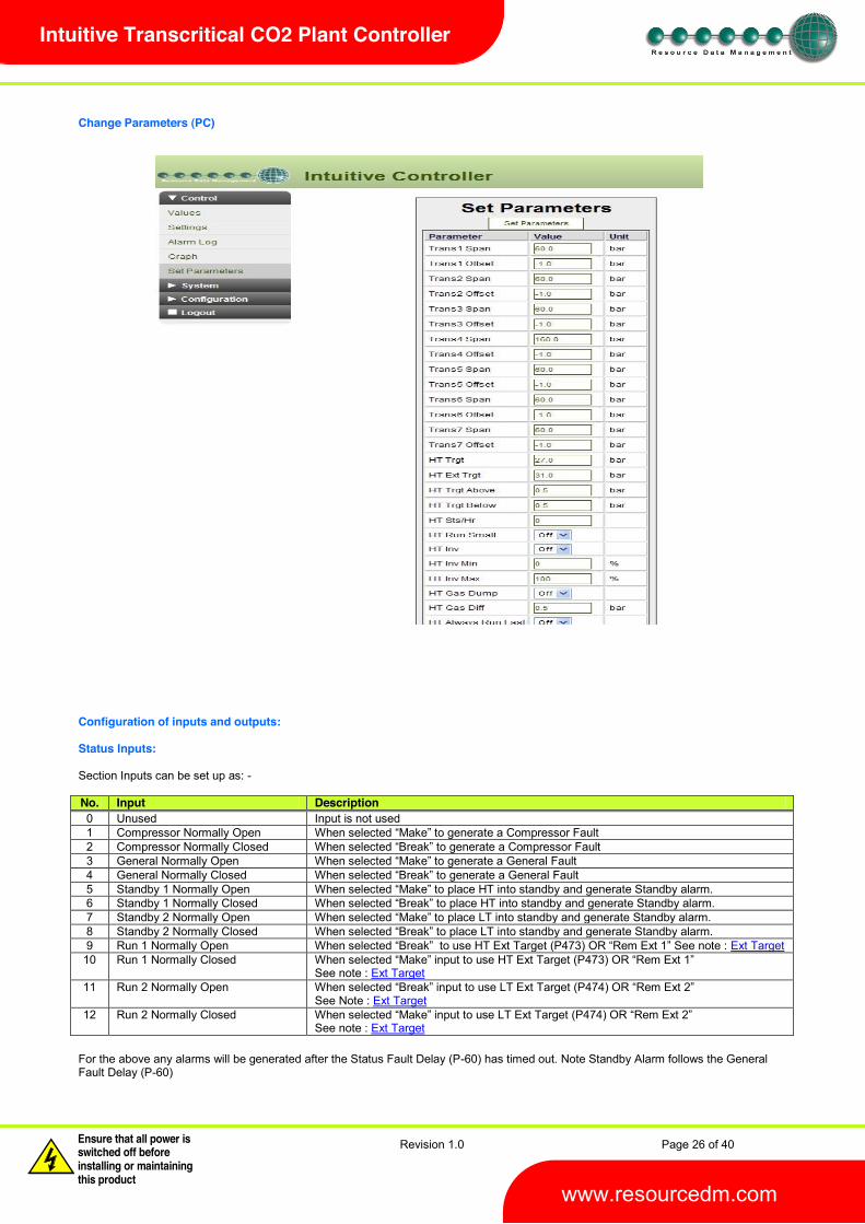
Change Parameters (PC) Configuration of inputs and outputs: Status Inputs: Section Inputs can be set up as: - No. Input Description 0 Unused Input is not used 1 Compressor Normally Open te a Compressor Fault 2 Compressor Normally Closed 3 General Normally Open 4 General Normally Closed 5 Standby 1 Normally Open 6 Standby 1 Normally Closed 7 Standby 2 Normally Open place LT into standby and generate Standby alarm. 8 Standby 2 Normally Closed 9 Run 1 Normally Open Ext Target
10 Run 1 Normally Closed See note : Ext Target
11 Run 2 Normally Open See Note : Ext Target
12 Run 2 Normally Closed See note : Ext Target
For the above any alarms will be generated after the Status Fault Delay (P-60) has timed out. Note Standby Alarm follows the General Fault Delay (P-60)
Revision 1.0 Page 27 of 40
Warning Please Note The specifications of the product detailed on this Set-Up Guide may change without notice. RDM Ltd. shall not be liable for errors or for incidental or consequential damages, directly and indirectly, in connection with the furnishing, performance or misuse of this product or document.
Ensure that all power is switched off before installing or maintaining this product www.resourcedm.com
Intuitive Transcritical CO2 Plant Controller
Ext Target HT/LT Pack Controller To use HT/LT Ext Target (P473/474) instead of HT/LT Target Pressure (P-20/40) A Stat
When input is activated the Target Pressure will change from (P-20/40) to (P473/474) When input is de-activated the Target Pressure will revert back to (P-20/40) Section Stages Stage Description Notes None Use this option to end the number of stages in the controller See note 7 Unused Use this option to skip a relay output within a stage Comp Use this option to assign a relay output to a compressor See note 5 Loader Use this option to assign a relay output to a compressor loader Inverter Use this option to assign a relay to an Inverter Trim Use this option to set a relay to a trim compressor See note 6 Comp Run Use this option to set a relay as a separate compressor used only when other
compressors are running See note 8
Note 5: In the configuration, at least 1 output must be assigned to a compressor. Loader outputs will not energise without a compressor being on. When assigning stages a Loader should follow the Compressor on which it is mounted. Note 6. This option can be used to delay the onset of the output energises. Once all the trim stages are on the inverter enable relay would be energised and the inverter analogue output would begin to ramp up. The trim stages would remain on until all other stages and the inverter are turned off. Note 8: This option is used to bring on a separate compressor. This output is active when any of the other defined compressors (Comp stages) are running. This output is off when the last compressor in its section is turned off. Note if only the inverter output is configured and no other Comp stages then the Comp Run is active when the inverter output is active. Alarm Relay Note 7. The alarm relay is assigned automatically to the first free power on this is likely to be relay 1, until programming of the output stage is complete. The relay is energised with no alarm and de-energised when in alarm. Stage Sizes Stage sizes will determine the order in which compressors or loaders are switched on and off. This is a relative number between 0 and 60, reflecting the size of the compressor (usually horse power) The default stage size is 0; stage sizes must be entered for correct operation. Operation (Fuzzy) Once the controller has been set-up and configured, normal operation will resume. If the appropriate Type has been selected the
ine the stages to bring on and off using the fuzzy logic rules and adhering to the starts/hr criteria. The response time for devices switching on and off can be varied by adjusting the response on and response off parameters (1 is the slowest response, 60 is the quickest). The fuzzy logic will attempt to optimise the compressor starts and keep them at a minimum. Before a compressor is switched on, Relay 1 will energise and the variable output will ramp to 100%, when it reaches this point, the fixed device (compressor or loader) ; will switch on and the variable output will begin its cycle again starting from 0%. When demand is satisfied, and all compressor relays are off, the variable output ramps down 0%, if demand is still satisfied, the enable relay de-energises. Operation (Staged)
e at least 1 relay assigned for the controller to operate correctly. More than one relay can be assigned to stages in a given section and the same relay can be used in multiple stages. Note a relay cannot be assigned in both HT and LT. As the pressure rises above the target setpoint, plus the target above value, the controller will enter Stage 1 after the stage on delay has expired. At this point any relay assigned in Stage 1 will come on and the stage on delay timer will be reset. If the pressure remains above the setpoint, plus the target above value, and the stage on delay has expired for a second time the controller will enter stage 2. At this point any relay assigned in Stage 2 will come on. Note if a relay has been assigned in Stage 1 but not used in Stage 2 then it will go off at this point. The reverse occurs when the pressure falls below the setpoint plus the target below value. The controller will step down the stages using the stage off delay (P-08) until all stages are off. When using a variable output as the pressure rises above target setpoint, plus target above, the variable speed output will ramp up from 0% to 100% without following the stage on delay. If the pressure stays above the target setpoint and the variable output is at 100% and the stage on delay has timed out then the controller will enter Stage 1. At this point the variable output will reset to 0% and start ramping up again towards 100%. If the pressure stays above the target setpoint and the variable output is at 100% and the stage on delay has

Revision 1.0 Page 28 of 40
Warning Please Note The specifications of the product detailed on this Set-Up Guide may change without notice. RDM Ltd. shall not be liable for errors or for incidental or consequential damages, directly and indirectly, in connection with the furnishing, performance or misuse of this product or document.
Ensure that all power is switched off before installing or maintaining this product www.resourcedm.com
Intuitive Transcritical CO2 Plant Controller
timed out then the controller will enter Stage 2. As the pressure drops below the setpoint, minus the target below, the variable output will ramp from 100% down to 0%, once the stage off delay expires the controller will stage down. Note if the variable output reaches 100% and the stage on delay has not expired the output will remain at 100% until the stage on delay has expired. For example : HT Pack has 4 Compressors the following could be set: - HT Stg1 : Rly 1 =On, HT Stg2 : Rly 1 and Rly 2 = On, HT Stg 3 : Rly 1 ,Rly 2 and Rly 3 = On. HT Stg 4 : Rly 1, Rly 2, Rly 3 and Rly 4 = On. This would stage relay 1 through to four on after the appropriate stage delay if the pressure is above the target setpoint and differentials. LT Pack would start as follows:- LT stg1: Rly 5 = On (Note: Starting at Relay 5 as the first 4 relays have already been allocated to Pack 1) Other operational features Invert Relays The operation of the relays can be inverted so that N/C contacts can be used for energisation. This can be done from the configure screen on web page. Choose the relay(s) you wish to invert and set them to on. This process can also be completed from the controller display. Navigate to the menu option rly and select the relay output you wish to invert for example r-05
t the N/C contact is in use. Please note: This operation does not invert the Alarm relay. The alarm relay is energised when there are no alarms present. USB Operation The following operations can be performed using a memory-stick plugged into the USB port: -
1. Export event log U-01 2. Export logged data U-02 3. Save configuration U-03 4. Load configuration U-04 5. Upgrade the software U-05
The above requires the user to enter the USB menu via the display and press enter at the appropriate display option. For example to save the current configuration insert a USB Memory stick into one of the USB Host ports, go to the USB software menu option, press enter, then the use the up key to scroll to U- completed. The file is transferred to the memory-stick in .zip format. The USB memory stick must be formatted as FAT32. Viewing Inputs and Outputs Apart from setting up the controller, you can also view the status of the inputs and outputs.
1. From the 2. You can now scroll through the IO tables as set out below. The tables you view will depend on the controller type configuration.
Input and Output Configuration Combined System (Plant Controller Board plus Expansion Board/s) Using a Plant Controller for controlling HT/LT Pack and an Expansion Board for controlling the Gas Cooler and Receiver Plant Controller Board
Inputs HT/LT Pack Controller Universal I/O 1 HT Suction Pressure Universal I/O 2 LT Suction Pressure Universal I/O 3 Pressure Monitor only Universal I/O 6 to 8 Unused Probes 1 to 8 Temperature Monitor only Status Input s 1 to 12 Compressor Faults, General Faults, Standby and Ext Target
Outputs HT/LT Pack Controller Relays 1 to 12 HT and LT Compressor Stages, Gas Dump Relays and Alarm Relay Universal I/O 4 HT Pack VSD Universal I/O 5 LT Pack VSD

Revision 1.0 Page 29 of 40
Warning Please Note The specifications of the product detailed on this Set-Up Guide may change without notice. RDM Ltd. shall not be liable for errors or for incidental or consequential damages, directly and indirectly, in connection with the furnishing, performance or misuse of this product or document.
Ensure that all power is switched off before installing or maintaining this product www.resourcedm.com
Intuitive Transcritical CO2 Plant Controller
Stepper Expansion Board See Intuitive Plant Controller Stepper & IO Expansion Module User Guide on RDM web site for more Information on Expansion Boards
Inputs Gas Cooler and Receiver Controller with stepper Valve Universal I/O 1 Gas Cooler Pressure Universal I/O 2 Receiver/Separator Pressure Universal I/O 3 Liquid Level sensor , or (Pressure Monitor if Liquid Level not being used) Universal I/O 4 Monitor Pressure only Temperature Probe 1 Gas Cooler Temperature Temperature Probe 2 Air On Cooler Temperature Temperature Probe 3 Air Off Cooler Temperature Temperature Probe 4 to 8 Unused Status Input 1 Extra Capacity Input Status Input 2 Receiver Low Level Status Input 3 Receiver High Level Status Input 4 to 12 Unused
Outputs Gas Cooler and Receiver Controller with stepper Valve Universal I/O 5 Gas Cooler Valve (HT VALVE) VSD Universal I/O 6 Gas Cooler Fan VSD Universal I/O 7 Receiver/Separator Bypass Valve (MT VALVE) VSD (If used) See : Note 3 Universal I/O 8 Auxiliary Compressor VSD Stepper Output 1 Receiver/Separator Bypass Stepper Valve (MT VALVE) (If used) See : Note 3 Stepper Output 2 to 6 Not Used Relay 1 Gas Cooler Fan Enable Relay 2 Transcritical Relay Relay 3 Receiver/Separator Bypass Valve (MT VALVE) Enable Relay 4 Auxiliary Compressor enable Note 3 : Receiver/Separator Bypass Valve (MT VALVE) can be either a Stepper Valve or a Variable Speed Drive IO Expansion Board (For Oil Monitoring)
Inputs Oil Monitoring Universal I/O 1 to 8 Unused Temperature Probe 1 to 8 Unused Status Input 1 to 8 Oil Fault 1 to 8
Outputs Oil Monitoring Relays / Stepper Outputs Unused (May be used in future development)

Revision 1.0 Page 30 of 40
Warning Please Note The specifications of the product detailed on this Set-Up Guide may change without notice. RDM Ltd. shall not be liable for errors or for incidental or consequential damages, directly and indirectly, in connection with the furnishing, performance or misuse of this product or document.
Ensure that all power is switched off before installing or maintaining this product www.resourcedm.com
Intuitive Transcritical CO2 Plant Controller
Input/Output Tables
Dual
Pac
k +
Gas
Coo
ler
(Fuz
zy T
ype
1)
Dual
Pac
k +
Gas
Coo
ler
(Sta
ged
Type
2)
Dual
Pac
k +
Gas
Coo
ler
+ O
il (F
uzzy
Typ
e 3)
Dual
Pac
k +
Gas
Coo
ler
+ O
il (S
tage
d Ty
pe 4
)
No. IO Range Units Comments I-01 HT Suction Pressure -3.4 to 180 Bar I-02 LT Suction Pressure -3.4 to 180 Bar I-03 Pressure 3 -3.4 to 180 Bar Monitor Pressure only I-04 Gas Cooler Pressure -3.4 to 180 Bar Used to ca
See : Gas Calculated Temperature
I-05 Receiver Pressure -3.4 to 180 Bar I-06 Pressure Input 6 -3.4 to 180 Bar Monitor Pressure (If not being used
for Liquid Level Detector)
I-07 Pressure Input 7 -3.4 to 180 Bar Monitor Pressure only I-10
I-17
Analogue Input 1 Analogue Input 8
-80 to +128 OC
I-18 Gas Cooler Temperature
-80 to +128 OC See : Gas Cooler Set Point
I-19 Gas Calculated Temperature
-80 to +128 OC
See : Gas Calculated Temperature
I-30
I-41
Digital Input 1 Digital Input 12
0 = OK 1 = Alarm
2 = Unused
I-50 HT Run 0 = Off, 1 = On 2 = Unused
I-51 LT Run 0 = Off, 1 = On 2 = Unused
I-54 Liquid Level 0 100 % I-60 Capacity Input 0 = Off, 1 = On
2 = Unused
I-61 Receiver Low Level
0 = OK 1 = Alarm
2 = Unused
I-62 Receiver High Level 0 = OK 1 = Alarm
2 = Unused
I-63 Cooler Air On -80 to +128 OC I-64 Cooler Air Off -80 to +128 OC I-70 I-77
Oil 1 Oil 8
0 = OK 1 = Alarm
2 = Unused
O-01
O-12
Relay 1
Relay 12
0 = Off 1 = On

Revision 1.0 Page 31 of 40
Warning Please Note The specifications of the product detailed on this Set-Up Guide may change without notice. RDM Ltd. shall not be liable for errors or for incidental or consequential damages, directly and indirectly, in connection with the furnishing, performance or misuse of this product or document.
Ensure that all power is switched off before installing or maintaining this product www.resourcedm.com
Intuitive Transcritical CO2 Plant Controller
O-15 Transcritical 0 = Off, 1 = On O-20 HT Stage 0 - 12 O-21 LT Stage 0 - 12 O-31 HT Variable Output 0 100 % O-32 LT Variable Output 0 100 % O-41 Optimisation Level
Pack 1 -3.4 to 180 Bar
O-42 Optimisation Level Pack 2
-3.4 to 180 Bar
O-72 HT Gas Dump 0 = Off, 1 = On O-73 LT Gas Dump 0 = Off, 1 = On O-74 Gas Cooler Setpoint -3.4 to 180 Bar
See : Gas Cooler Set Point
O-75 Gas Cooler Output 0 100 % O-76 Gas Fan Setpoint -3.4 to 180 Bar O-77 Gas Fan Output 0 100 % O-78 Receiver Output 0 100 % O-79 Aux Comp Output 0 100 % O-80 Gas Fan Output Enable 0 = Off, 1 = On O-81 Receiver Output Enable 0 = Off, 1 = On O-82 Aux Comp Output
Enable 0 = Off, 1 = On
S-01 HT Control States (0) Stabilise (1) Off (2) Initial (3) Cooler Fault (4) Normal (5) High Pressure (6) Low Pressure (7) Low Shut-down (8) Transducer Fail (9) Stand-by
S-02 LT Control States (0) Stabilise (1) Off (2) Initial (3) Cooler Fault (4) Normal (5) High Pressure (6) Low Pressure (7) Low Shut-down (8) Transducer Fail (9) Stand-by
S-03 Gas Cooler State (0) Stabilise (1) Initial (2) Pack Fault (3) Triple (4) SubCrit (5) TransCri (6) SuperCrit (7) Transducer Fail (8) Shutdown
Quickview
-out period to elapse.
Override The override function allows the user to switch output stages on or off. Press the override and enter button together for approx 3 seconds
-
-01 to r-12) and 4 20mA outputs (A-01 and A-02) For (r-01 to r- For (A-01 and A- -20mA outputs 1 and 2 0% to 100% Override will last for 30 seconds then the output will return to normal operation.

Revision 1.0 Page 32 of 40
Warning Please Note The specifications of the product detailed on this Set-Up Guide may change without notice. RDM Ltd. shall not be liable for errors or for incidental or consequential damages, directly and indirectly, in connection with the furnishing, performance or misuse of this product or document.
Ensure that all power is switched off before installing or maintaining this product www.resourcedm.com
Intuitive Transcritical CO2 Plant Controller
Info Button When this button is used, HT and LT analogue output values can be displayed. Probe Offsets Each probe input, displayed as C-01 to C-08 from the controller display menu, can have an offset applied; Up to ± 20O C in increments of 0.1O C. Display Messages The following messages can appear on the display during normal operation.
Display System status HP High Pressure alarm LP Low Pressure alarm Ft TrAn Pressure Transducer Fault Ft Fault Sd Low Pressure Shut-down CP (1 to 12) Compressor Fault
Compressor Run Fault Gn (1 to 12) General Fault Stby Controller in Standby Conf Configuration / Set up error
Network Alarms The table below shows the text and associated typrovide different alarm actions.
Alarm text Type # High Pressure Alarms 8 Low Pressure Alarms 9 Low Pressure Shutdown 10 Transducer Faults 6 General Faults 20 Compressor faults 3 Configuration Error 20 Controller in standby 20 Liquid Level Fault 6 Liquid Level High 4 Liquid Level Low 5 Gas Probe Fault 6 Gas Sensor Fault 6 Gas Cooler HP Shut Down 8 Gas Cooler LP Shut Down 9 Gas Cooler HP Open 8 Gas Cooler LP Open 9 Gas Cooler OT 4 Receiver Sensor Fault 6 Receiver High Pressure 8 Receiver Low Pressure 9 Receiver Low Level 13 Receiver High Level 13 Oil Fault 18 Board Offline 7

Revision 1.0 Page 33 of 40
Warning Please Note The specifications of the product detailed on this Set-Up Guide may change without notice. RDM Ltd. shall not be liable for errors or for incidental or consequential damages, directly and indirectly, in connection with the furnishing, performance or misuse of this product or document.
Ensure that all power is switched off before installing or maintaining this product www.resourcedm.com
Intuitive Transcritical CO2 Plant Controller
Specification Power requirements: Supply Voltage Range: 24 Vac ±10% or 24 Vdc ±10% Supply Frequency: 50 60 Hz ±10% Maximum supply current: <1 Amp Typical supply current: <1.0 Amp Class 2 Insulation: No protective Earth is required. A functional earth can be connected if the equipment is located
in an electrically noisy environment. Note : The use of centre tapped to earth transformers is not allowed. This is to prevent damage to the transformer and/or controller. The host equipment must provide adequate protection against contact to hazardous live parts. RDM advise the use of a suitable external over-current protection device. Warranty may be invalidated due to excess current being unlimited if there are no fuses/circuit breakers installed General Operating temperature range: +50C to +500C Operating Humidity: 80% maximum Storage temperature range: -200C to +650C Environmental: Indoor use at altitudes up to 2000m, Pollution Degree 1, Installation Category II. Voltage fluctuations not to exceed ±10% of nominal Voltage Size: 280mm (L) x 122mm (W) x 67mm (H) Weight: 750 Grams Safety: EN61010 EMC: EN61326; 1997 +Amdt. A1; 1998 Ventilation: There is no requirement for forced cooling ventilation Inputs Probe Input type See Set/change Units for probe types Digital Input type The preferred option is a 0 Volt return through a Volt free relay or 24 Vac referenced to the
supply Voltage. If a 24Vac signal is being sourced from the Plant controller power supply then do not ground the Digital Input common rail, this is grounded internally.
Comms: Ethernet 4-20mA 4-20mA current loop, use the 12 Vdc output to feed the device. Analogue Outputs
0 to 10 Volts DC or 0/4-20mA, Selected in the Front Panel Menu. A 50mA fuse is recommended for each Analogue output.
The 4-20mA output will not operate correctly if the target device input impedance is > 75 The 0-10V output will not operate correctly if the target device input impedance is < 10K
Relay Ratings All Relays 5A/250 Vac/AC1 (Resistive load) 5A/30 Vdc (Resistive) 2A/250 Vac cos 0.3 on N/O contact (Inductive Load) Interboard Comms CANBUS
Note end of line termination resistors must be fitted on the CANBUS network. One resistor should be fitted at the Intuitive Plant controller CANBUS network connector across the CAN High pin and the CAN Low pin. The second should be fitted to the last Expansion board on the CANBUS network and must be fitted across the CAN High pin and the CAN Low pin. The termination resistor value required is a 120Ohm and must have a tolerance of +/- 1% or better. The network should be wired in a daisy chain configuration. Only one Plant controller should be connected to a single CANBUS network. The maximum allowable network cable length is 500M in total from one end of the network to the other providing a suitable CANBUS network cable is utilised.

Revision 1.0 Page 34 of 40
Warning Please Note The specifications of the product detailed on this Set-Up Guide may change without notice. RDM Ltd. shall not be liable for errors or for incidental or consequential damages, directly and indirectly, in connection with the furnishing, performance or misuse of this product or document.
Ensure that all power is switched off before installing or maintaining this product www.resourcedm.com
Intuitive Transcritical CO2 Plant Controller
When connecting an expansion board to either the Intuitive Plant controller or another Expansion board the following should be observed. CANBus cable specification : CANBus communication cable should be of a standard to meet ISO11898 or equivalent CANbus Termination Link
Plant Controller/Expansion Board Expansion Board CAN High Connects to CAN High Screen Connects to Screen CAN Low Connects to CAN Low Ground Connects to Ground
Please note all the Intuitive Plant Controller and Expansion boards have a built-in termination resistor. A link is provided to allow the end user to enable or disable the end of line termination resistor..
Top
EnabledDisabled

Revision 1.0 Page 35 of 40
Warning Please Note The specifications of the product detailed on this Set-Up Guide may change without notice. RDM Ltd. shall not be liable for errors or for incidental or consequential damages, directly and indirectly, in connection with the furnishing, performance or misuse of this product or document.
Ensure that all power is switched off before installing or maintaining this product www.resourcedm.com
Intuitive Transcritical CO2 Plant Controller
Installation: Mounting on to a DIN rail Rear view. Clearances: The controller must have 10mm clearance above the top and 15mm clearance from the sides. Clearance at the front and rear is dependent on the site wiring. There is no requirement for forced cooling ventilation Cleaning: Do not wet the controller when cleaning. Clean the front by wiping with a slightly damped lint free cloth. Please note: The specifications of the product detailed on this set up guide may change without notice. RDM Ltd shall not be liable for errors or for incidental or consequential damages, directly or indirectly, in connection with the furnishing, performance or misuse of this product or document.

Revision 1.0 Page 36 of 40
Warning Please Note The specifications of the product detailed on this Set-Up Guide may change without notice. RDM Ltd. shall not be liable for errors or for incidental or consequential damages, directly and indirectly, in connection with the furnishing, performance or misuse of this product or document.
Ensure that all power is switched off before installing or maintaining this product www.resourcedm.com
Intuitive Transcritical CO2 Plant Controller
$./0$.)12()'$3),-1,4$

Revision 1.0 Page 37 of 40
Warning Please Note The specifications of the product detailed on this Set-Up Guide may change without notice. RDM Ltd. shall not be liable for errors or for incidental or consequential damages, directly and indirectly, in connection with the furnishing, performance or misuse of this product or document.
Ensure that all power is switched off before installing or maintaining this product www.resourcedm.com
Intuitive Transcritical CO2 Plant Controller
CO2 Pressure to Temperature Curve
$$$$$
$$$
$

Revision 1.0 Page 38 of 40
Warning Please Note The specifications of the product detailed on this Set-Up Guide may change without notice. RDM Ltd. shall not be liable for errors or for incidental or consequential damages, directly and indirectly, in connection with the furnishing, performance or misuse of this product or document.
Ensure that all power is switched off before installing or maintaining this product www.resourcedm.com
Intuitive Transcritical CO2 Plant Controller
566#&7)8$9$!:6)2,;$!1,&<7(2#1$.=&')=&$$
For 4-20mA type transducers the diagram below shows the connections to the Intuitive Controller: - Note: The Earth connection on transducer is not necessary unless in an electrically noisy environment.
$$$$$$$$$

Revision 1.0 Page 39 of 40
Warning Please Note The specifications of the product detailed on this Set-Up Guide may change without notice. RDM Ltd. shall not be liable for errors or for incidental or consequential damages, directly and indirectly, in connection with the furnishing, performance or misuse of this product or document.
Ensure that all power is switched off before installing or maintaining this product www.resourcedm.com
Intuitive Transcritical CO2 Plant Controller
$
>,1'$&(4?#1<$ PR0651-STEP: Kit comes with PR0650-TCO2 Intuitive Transcritical CO2 Plant Controller PR0660 Intuitive Plant Stepper Module PR0620 Plant Controller LED Panel Mount Display PR0615 Plant Controller Colour Touch Display PR0625 2 x 24V 2A Din Mountable Power Supply PR0170 2 x PT1000 Air Probe PR0180 5 x PT1000 Pipe Probe PR0651-STEP OIL: Kit comes with PR0650-TCO2 Intuitive Transcritical CO2 Plant Controller PR0660 Intuitive Plant Stepper Module PR0661 Intuitive Plant I/O Module PR0620 Plant Controller LED Panel Mount Display PR0615 Plant Controller Colour Touch Display PR0625 2 x 24V 2A Din Mountable Power Supply PR0170 2 x PT1000 Air Probe PR0180 5 x PT1000 Pipe Probe
$$$$$$$$$$$$$$$$$$$$$$$$

Revision 1.0 Page 40 of 40
Warning Please Note The specifications of the product detailed on this Set-Up Guide may change without notice. RDM Ltd. shall not be liable for errors or for incidental or consequential damages, directly and indirectly, in connection with the furnishing, performance or misuse of this product or document.
Ensure that all power is switched off before installing or maintaining this product www.resourcedm.com
Intuitive Transcritical CO2 Plant Controller
$
+#*)<)=&$@)<'=1:$ Revision Date Changes
1.0 20/04/2011 1st issue