
Transcritical R744 (CO2) heat pumps - Technician Manual - Cetiat
62
CENTRE TECHNIQUE DES INDUSTRIES AÉRAULIQUES ET THERMIQUES Domaine Scientifique de la Doua - 25, avenue des Arts - BP 2042 - 69603 Villeurbanne Cedex - France Tél. +33 (0)4 72 44 49 00 - Fax. +33 (0)4 72 44 49 49 - www.cetiat.fr - E. Mail : [email protected] Livraisons : Domaine Scientifique de la Doua - 54, avenue Niels Bohr - 69100 Villeurbanne Siret 775 686 967 00024 - Ape 731 Z Auteur : Ahmed BENSAFI - Bernard THONON Diffusion : Confidential Date : October 2007 Rapport 2414173 Transcritical R744 (CO 2 ) heat pumps Technician's Manual
Transcript of Transcritical R744 (CO2) heat pumps - Technician Manual - Cetiat
CENTRE TECHNIQUE DES INDUSTRIES AÉRAULIQUES ET THERMIQUES
Domaine Scientifique de la Doua - 25, avenue des Arts - BP 2042 - 69603 Villeurbanne Cedex - FranceTél. +33 (0)4 72 44 49 00 - Fax. +33 (0)4 72 44 49 49 - www.cetiat.fr - E. Mail : [email protected]
Livraisons : Domaine Scientifique de la Doua - 54, avenue Niels Bohr - 69100 VilleurbanneSiret 775 686 967 00024 - Ape 731 Z
Auteur : Ahmed BENSAFI - Bernard THONON
Diffusion : Confidential
Date : October 2007
Rapport 2414173
Transcritical R744 (CO2) heat pumpsTechnician's Manual

Rapport 2414173 - October 2007__________________________________________________________________
__________________________________________________________________________________________
SHERPHA PROJECT - Transcritical R744 Heat Pumps – Technician's Manual 2/62
TABLE OF CONTENTS
1. NATURAL REFRIGERANTS.......................................................................................4
1.1. Refrigeration and heat pumping .................................................................................4
1.2. A brief history of refrigerants.....................................................................................5
1.3. Natural refrigerants applications ................................................................................6
1.3.1. Isobutane (R600a) ...............................................................................................8
1.3.2.Propane (R290)....................................................................................................8
1.3.3.Ammonia (R717).................................................................................................8
2. CARBON DIOXIDE ......................................................................................................9
2.1. Properties....................................................................................................................9
2.2. Comparison of subcritical and transcritical cycles...................................................13
2.2.1.Characteristics of subcritical cycles ..................................................................13
2.2.2.Heat pumping with R744 : the transcritical cycle .............................................14
2.3. Optimum pressure with the transcritical cycle .........................................................15
2.4. Transcritical cycle vs. Traditional cycle...................................................................17
3. R744 HEAT PUMPS TECHNOLOGY........................................................................17
3.1. The Ecocute system for tap water and heating.........................................................18
3.2. Green and Cool Chiller Systems ..............................................................................22
3.3. Vending machines and bottle coolers.......................................................................23
4. COMPONENTS FOR R744 HEAT PUMPS ...............................................................25
4.1. Compressors .............................................................................................................25
4.2. Evaporators...............................................................................................................31
4.3. Gas coolers ...............................................................................................................32
4.4. Expansion devices and controls................................................................................34
5. SAFETY GUIDELINES WHEN USING R744 IN HEAT PUMPS............................37
5.1. R744 effects on health ..............................................................................................37

Rapport 2414173 - October 2007__________________________________________________________________
__________________________________________________________________________________________
SHERPHA PROJECT - Transcritical R744 Heat Pumps – Technician's Manual 3/62
5.2. R744 in heat pumps..................................................................................................38
5.2.1.Pressure at standstill ..........................................................................................38
5.2.2.Operating temperatures and pressures...............................................................39
5.2.3.Material compatibility .......................................................................................39
5.2.4.Water and R744.................................................................................................40
6. SERVICING AND MAINTENANCE ASPECTS .......................................................43
6.1.1.Evacuating R744 : the expansion process .........................................................43
6.1.2.Recharging R744 heat pumps............................................................................44
6.1.3.R744 containers and recharge system ...............................................................46
ANNEX 1 : INFORMATION ON MARKETED DOMESTIC HEAT PUMPS.................48
ANNEX 2 : CHILLERS.......................................................................................................56
ANNEX 3 : SAFETY DATA SHEET .................................................................................58
SELECTED REFERENCES................................................................................................62
Rapport 2414173 - October 2007__________________________________________________________________
__________________________________________________________________________________________
SHERPHA PROJECT - Transcritical R744 Heat Pumps – Technician's Manual 4/62
1. NATURAL REFRIGERANTS
1.1. Refrigeration and heat pumping
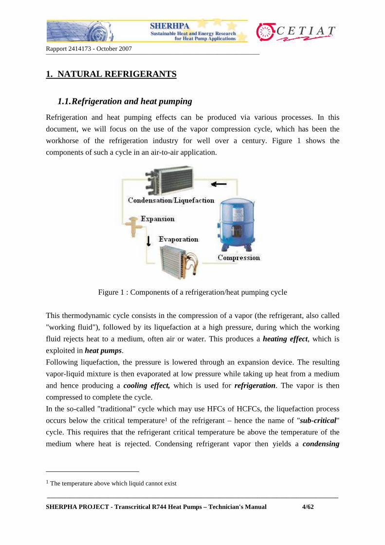
Refrigeration and heat pumping effects can be produced via various processes. In this
document, we will focus on the use of the vapor compression cycle, which has been the
workhorse of the refrigeration industry for well over a century. Figure 1 shows the
components of such a cycle in an air-to-air application.
Figure 1 : Components of a refrigeration/heat pumping cycle
This thermodynamic cycle consists in the compression of a vapor (the refrigerant, also called
"working fluid"), followed by its liquefaction at a high pressure, during which the working
fluid rejects heat to a medium, often air or water. This produces a heating effect, which is
exploited in heat pumps.
Following liquefaction, the pressure is lowered through an expansion device. The resulting
vapor-liquid mixture is then evaporated at low pressure while taking up heat from a medium
and hence producing a cooling effect, which is used for refrigeration. The vapor is then
compressed to complete the cycle.
In the so-called "traditional" cycle which may use HFCs of HCFCs, the liquefaction process
occurs below the critical temperature1 of the refrigerant – hence the name of "sub-critical"
cycle. This requires that the refrigerant critical temperature be above the temperature of the
medium where heat is rejected. Condensing refrigerant vapor then yields a condensing
1 The temperature above which liquid cannot exist
Rapport 2414173 - October 2007__________________________________________________________________
__________________________________________________________________________________________
SHERPHA PROJECT - Transcritical R744 Heat Pumps – Technician's Manual 5/62
pressure that is below the refrigerant critical pressure. In this cycle, condensing pressure and
temperature are linked by a unique relationship that depends on the nature of the refrigerant.
In a "transcritical" cycle, the liquefaction process (or gas cooling) occurs above the critical
pressure, while evaporation occurs at a pressure below the critical pressure. With a few
exceptions, all cycles use working fluids below their critical pressure.
1.2. A brief history of refrigerants
Briefly stated, the history of refrigerants can be divided into three periods :
- A first era which started roughly around 1830 and lasted up to
about 1930, where any available substance that produced
refrigeration was used. This era was qualified as the "whatever
worked" period, since the main selection criterion for a refrigerant
was its ability to be used in practical systems, regardless of its
toxicity, flammability and compatibility with the environment.
Although most of them were toxic and/or flammable, solvents and volatile fluids were
then used. With the development of comfort air conditioning and refrigeration to a very
large scale and to the public at large, new and safer refrigerants became necessary.
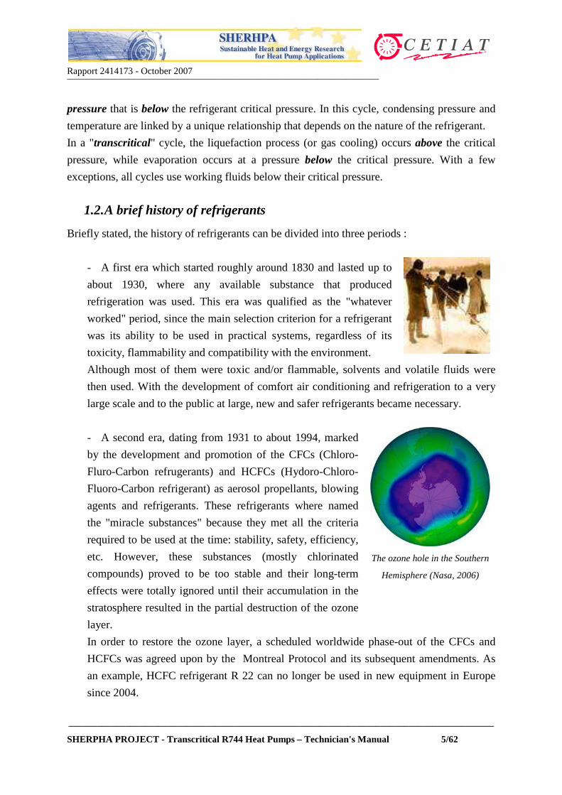
- A second era, dating from 1931 to about 1994, marked
by the development and promotion of the CFCs (Chloro-
Fluro-Carbon refrugerants) and HCFCs (Hydoro-Chloro-
Fluoro-Carbon refrigerant) as aerosol propellants, blowing
agents and refrigerants. These refrigerants where named
the "miracle substances" because they met all the criteria
required to be used at the time: stability, safety, efficiency,
etc. However, these substances (mostly chlorinated
compounds) proved to be too stable and their long-term
effects were totally ignored until their accumulation in the
stratosphere resulted in the partial destruction of the ozone
layer.
The ozone hole in the Southern
Hemisphere (Nasa, 2006)
In order to restore the ozone layer, a scheduled worldwide phase-out of the CFCs and
HCFCs was agreed upon by the Montreal Protocol and its subsequent amendments. As
an example, HCFC refrigerant R 22 can no longer be used in new equipment in Europe
since 2004.

Rapport 2414173 - October 2007__________________________________________________________________
__________________________________________________________________________________________
SHERPHA PROJECT - Transcritical R744 Heat Pumps – Technician's Manual 6/62
- A third era, dating from 19942, during which HFCs
(Hydro-Fluoro-Carbon refrigerants) have been massively
introduced in the AC&R industry. Because of their nil
contribution to ozone depletion, these substances were
promoted as the new "miracle" solution to the global
environmental problems. Kyoto 1999 : HFCs are put in
a "basket" of GHG substances
However, the HFCs have been listed amongst the substances contributing to global
warming (Greenhouse Gases – GHG) in the Kyoto Protocol in 1999, and the widespread
use of these refrigerants is not expected to last.
This brief look at history shows that as refrigerants evolved, no global approach has been
adopted to simultaneously address the various issues, mainly due to the lack of knowledge
(the effect of chlorine in the ozone layer was only discovered in 1975), but also because
scientific evidence of the effects of refrigerants was not acknowledged.
So far, mainly synthetic, man-made substances, have been used as refrigerants, and their
environmental effects could only be identified on the long term.
Table 1 summarizes the properties and environmental impacts of some refrigerants. This
Table shows that no progress has been made in terms of global warming potential when
switching from HCFCs to the HFC family. With climate change becoming a major concern
worldwide, the use of HFCs will be regulated.
It is noteworthy that for automotive air conditioning applications, the EC has already
scheduled a progressive phase-out of R134a as of year 2011, while limiting the GWP value of
refrigerants to be used in new car models to a value of 150. In September 2007, the German
automakers association (VDK) selected carbon dioxide as its preferred R134a alternative for
automobile air conditioning.
1.3. Natural refrigerants applications
Some European countries, such as Denmark, have already locally enforced
rules to limit the use of HFCs. This trend is spreading to other European
countries. With increasing environmental awareness, it is therefore
expected that many refrigeration applications presently using HFCs will
require other refrigerants.
2 This date marks the introduction of refrigerant R134a in automobile air conditioning

Rapport 2414173 - October 2007__________________________________________________________________
__________________________________________________________________________________________
SHERPHA PROJECT - Transcritical R744 Heat Pumps – Technician's Manual 7/62
Table 1 : Environmental impacts and properties of some refrigerants
Fluid
Boiling
point
(°°°°C)
Critical
temperature
(°°°°C)
Critical
pressure
(bar)
ODP 1GWP
(100 yrs)Oil Flam.
R12 -29 100.9 40.6 0.9 8100 mineral no
R22 -40.8 96.2 49.8 0.055 1500 mineral no
Pure HFCs
R23 -82.1 25.6 48.2 0 12000 ester no
R32 -51.6 78.4 58.3 0 650 ester yes
R125 -48.5 68.0 36.3 0 2500 ester no
R143a -47.6 73.1 37.6 0 4300 ester yes
R134a -26.5 101.1 40.7 0 1200 ester no
R152a -25.0 113.5 45.2 0 140 ester yes
HFC mixtures
R407C3 -44.0 86.8 46.0 0 1600 ester no
R410A2 -50.5 72.5 49.6 0 1900 ester no
R404A2 -46.4 72.1 37.4 0 3300 ester no
Natural refrigerants
R290
(propane)
-42.1 96.8 42.5 0 < 20 mineral yes
R600a(isobutane)
-11.7 135.0 36.5 0 < 20 mineral yes
CO2
(R744)-56.6 @5.2 bars
31.0 73.8 0 1 PAG no
R717(ammonia)
-33.3 132.2 113.5 0 0 mineral yes
1: reference R112 : azeotrope or quasi-azeotrope 3: average of dew and bubble point temperatures
However, as of year 2007, there is virtually no ideal alternative to the current HFC
refrigerants and, provided all the technological challenges are dealt with (in terms of safety,
equipment mechanical resistance to working pressures, flammability, etc), natural refrigerants
seem to be the most viable options, particularly in heat pumping equipment. The applications
of some natural fluids are discussed below, while a specific section will be devoted to carbon
dioxide.

Rapport 2414173 - October 2007__________________________________________________________________
__________________________________________________________________________________________
SHERPHA PROJECT - Transcritical R744 Heat Pumps – Technician's Manual 8/62
1.3.1. Isobutane (R600a)
Isobutane is a hydrocarbon, and hence is flammable. With thermodynamic properties that are
very similar to those of R134a, isobutane was used in Germany as early as 1992 to replace
R12. It is nowadays used in the great majority of domestic refrigerators. These appliances
require small refrigerant charges (typically 70 to 150 g) and are hermetic. Hence, no accident
has been reported so far in these household applications. Isobutane presents other advantages,
such as its compatibility with mineral oil and better energy efficiency than that of R134a. As a
by-product of the oil industry, isobutane is cheaper than R134a. The use of isobutane requires
minimal design changes, such as the relocation of potential ignition sources outside of the
refrigerated compartment. Isobutane is used worldwide, except in the USA, where legal
liability fears over the long-term inhibit manufacturers to market hydrocarbon systems.
1.3.2. Propane (R290)
With a boiling point of –42°C, propane is an excellent alternative to R22 as it requires similar
working pressures. An added advantage is that except for added safety measures because if its
flammability, virtually no design change is required in systems when switching from R22 to
propane. The combination of its good thermodynamic and thermophysical properties yields
systems that are at least as energy efficient as those working with R22. The use of propane is
increasing in countries where regulations allow it.
When used on the high temperature side of a cascade refrigeration system, propane provides
cooling to condense a lower temperature fluid. Hence, propane can be combined with carbon
dioxide in cascade systems that are used in large food processing or refrigeration plants with
both high energy efficiency and minimum environmental impact. Propane can also be used
for heat pump applications, particularly in systems using secondary fluids (water or glycols)
to absorb and reject heat. In this case, a compact sealed unit can be designed, thus reducing
both flammability risks and refrigerant charge.
1.3.3. Ammonia (R717)
Ammonia has been continuously used throughout modern refrigeration history, i.e. more than
130 years, despite its numerous drawbacks. It is toxic and flammable in concentrations
between 15.5 and 28% in air. It is not compatible with copper, thus requiring other materials
of construction.
With its small molecular weight and high latent heat, ammonia systems require much smaller
refrigerant flow rates than those using HFCs. Its thermodynamic and thermophysical
properties also yield very efficient refrigeration systems. Because of its acute toxicity,
Rapport 2414173 - October 2007__________________________________________________________________
__________________________________________________________________________________________
SHERPHA PROJECT - Transcritical R744 Heat Pumps – Technician's Manual 9/62
stringent regulations apply for ammonia systems, which require close monitoring and highly
skilled engineers and technicians. Ammonia is often used in large stores and in process
refrigeration. With the development of small-charge equipment, ammonia may be used in
smaller capacity units.
2. CARBON DIOXIDE
Carbon dioxide (CO2) is not a new refrigerant. Rather, it was "rediscovered" in the early 90's
at the Norwegian University of Science and Technology (NTNU). The use of carbon dioxide
as a refrigerant lasted for well over a century. Its application has been progressively
discontinued, until it was abandoned in the mid-50s, with the widespread use of the CFC
refrigerants, which were more efficient, more stable and safer. This section will summarize its
physical properties and examine its particularities when applied as a refrigerant. CO2
refrigerant will be referred to as "R744" in the following.
2.1. Properties
R744 is a versatile material, being used in many processes and applications - each of which
takes advantage of one or more these characteristics: reactivity, inertness and coldness
(mostly when used in direct-contact refrigeration). Common uses include consumption as a
raw material for production of various chemicals; a working material in fire extinguishing
systems; carbonation of soft drinks; freezing of food products, chilling of meats prior to
grinding; refrigeration and maintenance of ideal atmospheric conditions during transportation
of food products to market, etc.
R744 is present in the atmosphere at concentration3 levels of about 380 ppm. Exhaled air
contains about 4% carbon dioxide. At normal conditions, it is gaseous. R744 is odorless at
low concentrations and slightly toxic with a slightly pungent, acid taste.
It is widely available as it occurs naturally and it is a by-product of fossil fuel combustion and
other industrial processes. It combines with water in air to form carbonic acid which corrodes
metals, limestone and marble.
R744 will not burn or support combustion. Air with a carbon dioxide content of more than
10% will extinguish an open flame. Breathing air that contains more than 10% R744 can be
life-threatening. This corresponds to spreading uniformly about 24 kg of R744 in a
workshop that is 4 m wide, 10 m long and 3 m in height.
3 one ppm is equivalent to one cubic centimeter per cubic meter

Rapport 2414173 - October 2007__________________________________________________________________
__________________________________________________________________________________________
SHERPHA PROJECT - Transcritical R744 Heat Pumps – Technician's Manual 10/62
Gaseous R744 is 1.5 times heavier as air. Therefore, when released to the air it will
concentrate at low elevations.
R744 will form "dry ice" at -78.4ºC. One kg of dry ice has the cooling capacity of 2 kg of
ordinary ice. Gaseous or liquid carbon dioxide, stored under pressure, will form dry ice
through an auto-refrigeration process if rapidly depressurized.
Figures 2 and 3 show the thermodynamic properties of R744. Compared to other fluids
traditionally used as refrigerants, its critical point at 31°C is very low and its critical pressure
at about 74 bars is high. These differences have, as shall be discussed, important
consequences on heat pumping cycles using R744.
Figure 2 : Pressure-Temperature phase diagram of R744 (Danfoss)

Rapport 2414173 - October 2007__________________________________________________________________
__________________________________________________________________________________________
SHERPHA PROJECT - Transcritical R744 Heat Pumps – Technician's Manual 11/62
Figure 3 : Comparison of evaporating pressures
Note that below a pressure of 5.2 bar, solid and gaseous R744 phases may co-exist at low
temperature. This behavior is totally different from that observed with traditional refrigerants,
and will have important consequences on the operation, servicing and maintenance of a
system working with R744. Figure 3 compares the evaporating operating pressures of R744 to
those encountered with R410A and R404A. It can be observed that R744 systems will require
to operate a much higher pressures than conventional systems.

Rapport 2414173 - October 2007__________________________________________________________________
__________________________________________________________________________________________
SHERPHA PROJECT - Transcritical R744 Heat Pumps – Technician's Manual 12/62
Figure 4 : R744 Mollier Diagram
Rapport 2414173 - October 2007__________________________________________________________________
__________________________________________________________________________________________
SHERPHA PROJECT - Transcritical R744 Heat Pumps – Technician's Manual 13/62
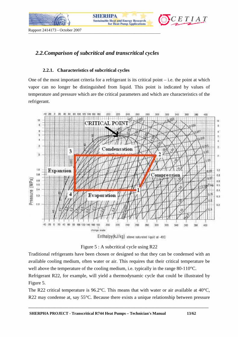
2.2. Comparison of subcritical and transcritical cycles
2.2.1. Characteristics of subcritical cycles
One of the most important criteria for a refrigerant is its critical point – i.e. the point at which
vapor can no longer be distinguished from liquid. This point is indicated by values of
temperature and pressure which are the critical parameters and which are characteristics of the
refrigerant.
Figure 5 : A subcritical cycle using R22
Traditional refrigerants have been chosen or designed so that they can be condensed with an
available cooling medium, often water or air. This requires that their critical temperature be
well above the temperature of the cooling medium, i.e. typically in the range 80-110°C.
Refrigerant R22, for example, will yield a thermodynamic cycle that could be illustrated by
Figure 5.
The R22 critical temperature is 96.2°C. This means that with water or air available at 40°C,
R22 may condense at, say 55°C. Because there exists a unique relationship between pressure

Rapport 2414173 - October 2007__________________________________________________________________
__________________________________________________________________________________________
SHERPHA PROJECT - Transcritical R744 Heat Pumps – Technician's Manual 14/62
and saturation temperature for a condensing pure substance, its pressure will be 21.8 bars
(abs).
Note that, for a given installation, this condensing pressure will in practice depend mainly
upon the following parameters :
• The water (or air) flow rate and available temperature;
• The charge of refrigerant into the system and the condenser size.
In this installation, the refrigerant flow rate is controlled by the expansion device (e.g.
capillary tube, thermostatic expansion valve, electronic expansion valve). This device controls
the amount of superheat at the suction of the compressor and ensures that no liquid droplets
are carried out from the evaporator.
Put shortly, heat pumps using "traditional" fluids such as HFCs and HCFCs operate with :
• condensing pressures that depend only on cooling medium conditions and on the
refrigerant charge. The condensing pressure is much lower than the refrigerant critical
pressure. So far, R410A is the refrigerant that required the highest operating pressure – its
upper limit being roughly 40 bars.
• Refrigerant flow rates that are controlled via an expansion device in order to avoid carry-
over of liquid droplets to the compressor suction. The expansion device set point is a
value of superheat at compressor suction.
2.2.2. Heat pumping with R744 : the transcritical cycle
As mentioned previously, the critical temperature of R744 is around 31°C. If ambient air is
used to cool on the high pressure side and is available at 35°C for example, it will not be
possible to condense the refrigerant. Rather, the refrigerant discharged from the compressor
will be cooled as a "supercritical" fluid because this process occurs at a pressure higher than
the critical pressure (74 bars). Such a cycle is illustrated in a Mollier Diagram in Figure 6.
In this illustrative cycle, R744 evaporates at 30 bars and is then compressed to 120 bars. Upon
compression, it reaches a temperature of 120°C. It is then cooled in a "gas cooler", expanded
and is evaporated to complete the cycle.
The main features of the transcritical cycle are then as follows:
• The cycle operates at much high pressures than the traditional cycle – typically between
30 bars (evaporator side) and 130 bars (gas cooler side);

Rapport 2414173 - October 2007__________________________________________________________________
__________________________________________________________________________________________
SHERPHA PROJECT - Transcritical R744 Heat Pumps – Technician's Manual 15/62
• The high pressure is no longer fixed by the cooling fluid temperature or flow rate;
therefore, there is a need to control this parameter;
• The high pressure refrigerant is not "condensed" – it is cooled as a supercritical fluid;
• In most cases, the refrigerant flow rate is not fixed based on the value of superheat at
compressor suction.
• The more refrigerant charge there is in the high pressure side, the higher the pressure will
be.
Figure 6 : A transcritical cycle using R744
2.3. Optimum pressure with the transcritical cycle
It was seen that for the subcritical cycle, the condenser pressure was fixed by the condensing
temperature, which in turn is a function of the condenser size and the cooling fluid flow rate
and temperature.
For the transcritical cycle, the gas cooler pressure is not a function of the R744 temperature,
because there is no unique relationship between temperature and pressure above the critical
point. This means that the system can operate at different values of high pressure, which can
be set by the control scheme.
Gas cooling above thecritical point

Rapport 2414173 - October 2007__________________________________________________________________
__________________________________________________________________________________________
SHERPHA PROJECT - Transcritical R744 Heat Pumps – Technician's Manual 16/62
In such a system, the pressure is therefore fixed by a control device so that the cycle operates
under optimum conditions, yielding the best energy efficiency.
Energy efficiency is defined as the amount of useful energy divided by the amount of input
energy. Hence, in heating mode, the energy efficiency, or Coefficient of Performance is
defined as :
)(
)(
kWPowerElectric
kWyHeatingDutCOP =
Figure 7a : Duty vs. Electric power Figure 7b : Performance vs. Discharge pressure
Figure 7a shows a cycle operated at a given value of high pressure. At this value, the system
requires a heat input q at the evaporator and a work input w to the compressor. The delivered
heat duty at the gas cooler is therefore q+w.
Under these conditions, the R744 refrigerant at exit of the gas cooler reaches a temperature T.
If the cycle is operated at a different values of high pressures and a constant value of
temperature T, both q and w will vary, and so will the value of COP.
Figure 7b shows the variation of COP when the high pressure is allowed to vary. It can
observed that there exists a value of pressure (called "optimal pressure") for which the COP is
highest.
Thus, the most efficient heat pumps will use control schemes that enable high pressure control
during operation. However, some systems also use simpler methods such as expansion
through a capillary tube, or some simple control scheme that enables operation at fixed high
pressure. As a rule of thumb, the optimal pressure is approximately given by the following
equation :86.2 += exitopt TP

Rapport 2414173 - October 2007__________________________________________________________________
__________________________________________________________________________________________
SHERPHA PROJECT - Transcritical R744 Heat Pumps – Technician's Manual 17/62
where Popt is expressed in bars and Texit is the R744 temperature in °C at exit of the gas cooler.
Thus, a gas cooler exit temperature of 45°C requires a high pressure of about 125 bars. This
equation is valid for temperatures between about 38 and 53°C.
2.4. Transcritical cycle vs. Traditional cycle
Table 2 summarizes the main design differences between the subcritical (traditional) cycle
and the R744 transcritical cycle.
As mentioned in the previous sections, the main differences lie in the pressure levels (both
during operation and at standstill) and the methods implemented to ensure the control of high
pressure and refrigerant flow rate.
Table 2 : Main differences between transcritical R744 cycle and subcritical cycle
Cycle parameters Subcritical Transcritical CO2
High pressure cooling – heat rejection device
Condenser – Vapor condenses at constant temperature
Gas cooler – CO2 undergoes large temperature change
Discharge pressure HFCs : from 10 to 40 bars from 90 to 130 bars
Suction pressure HFCs : from 2 to 9 bars from 25 to 50 bars
Refrigerant discharge temperature
Usually less than 95°C Up to 140°C
Expansion device controlsBy superheat set point or fixed flow expansion device
Usually used to control high pressure of CO2
High pressure controls (excluding safety shut-down controls)
Not controlled - Pressure is set by condensation temperature – usually 40 bars max
Required - Up to 130 bars
Refrigerant state @ standstill Partly liquid and partly vapor
Gas (supercritical) above 31°C ambient; vapor –liquid mixture below 31°C. Can become solid upon cooling below P<6 bars !
System pressure @ standstill (T ambient >31°C)
Refrigerant vapor pressure at ambient air temperature
At least 74 bars – can be higher, depending on charge and temperature.
3. R744 HEAT PUMPS TECHNOLOGY
In Section 2, the basics of the transcritical cycle were examined. In this section, some R744
applications (both for cooling and/or heating) will be surveyed, with a focus on the

Rapport 2414173 - October 2007__________________________________________________________________
__________________________________________________________________________________________
SHERPHA PROJECT - Transcritical R744 Heat Pumps – Technician's Manual 18/62
technology of the components. Only applications which are marketed or are at a noteworthy
stage of development as of year 2007 will be included herein. Industrial applications, air
conditioning and mobile air conditioning systems will not be covered.
Marketed applications cover :
• Tap water heating;
• Space heating;
• Chilled water for air conditioning;
• Commercial refrigeration (positive and negative temperature levels).
While the water heating applications have been marketed only in Japan, some commercial
refrigeration and air conditioning applications have been commercialized in Europe. During
2007, a few Japanese heat pumps have been installed in Europe (mainly in Sweden) for tap
water heating and residential heating.
3.1. The Ecocute system for tap water and heating
EcoCute is a brand name that applies to a system
which is made by 6 Japanese manufacturers (Denso,
Daikin, Sanyo, Matsushita Electric Industrial,
Hitachi Appliances, Mitsubishi Electric and
Sanden) and marketed under about 14 names. The
brand name is derived from the Japanese word
"kyuto" which means "hot water". The development
of the Ecocute was motivated by the need to
produce hot water at a cheaper cost, while operating
at reduced electricity tariffs. Sanyo is one of the
main manufacturers, releasing an Ecocute unit that
produces hot water and heating water. Figure 8
shows the heat pump and associated water tank.
Figure 8 : Sanyo Ecocute(www.sanyoaircon.com)
It is noteworthy the heat pump looks just like any other traditional air outdoor unit or
minichiller on the market. This outdoor unit has neither an integrated water tank, nor a water
pump. In addition to the electrical connections, only the water connections are required. The
water distribution system inside the house remains the same as with other heating systems.
Figure 9 shows the flow diagram of such a unit. The water circulates inside the tank and is
heated by the heat pump unit, as required. Water is withdrawn from the tank to feed the
radiators or space heating system and then returns to the tank. The tap water from the main

Rapport 2414173 - October 2007__________________________________________________________________
__________________________________________________________________________________________
SHERPHA PROJECT - Transcritical R744 Heat Pumps – Technician's Manual 19/62
water supply is fed to a coil inside the tank. It is then heated and routed to the different taps
(kitchen, shower, etc.). Supplemental electrical heaters inside the tank allow for an increase in
water temperature if the heat pump does not provide sufficient heating.
Figure 9 : Flow diagram of the Sanyo Ecocute (www.sanyoaircon.com)
Table 3 shows the claimed performance of this product, depending on the water tank model
electrical input (3-phase and single-phase).
Note that this unit is claimed to work down to
outdoors temperatures of –15°C without loss
in heating duty. Various Ecocute models from
other manufacturers are shown in Figure 10.
A Hitachi model shown in Figure 10 is made
up of two units connected in series. This heat
pump does not have a large tank. It produces
instant hot water, and is not intended for
space heating. It is designed to be installed
outdoors, thus saving indoors space. Figure 10 : Various Ecocute models(www.heatpumpcentre.org)

Rapport 2414173 - October 2007__________________________________________________________________
__________________________________________________________________________________________
SHERPHA PROJECT - Transcritical R744 Heat Pumps – Technician's Manual 20/62
Table 3 : Sanyo Ecocute Performance (www.sanyoaircon.com)
SHP-TH22DDN SHP-TH22DHN
kWW/WkW
W/WkW
W/W
Power supply Heat pump unit V Tank unit V 400 / 3+N 230 / 3+N
A 20 30
lkg/cm2
kW 9.0 7.05Dimensions Net H/W/D mm Shipment H/W/D mmWeight Net/Shipping kg
(kg)dB-A
Dimensions Net H/W/D mm Shipment H/W/D mmWeight Net/Shipping kg
Heat pump Unit SHP-C45DENTank unit
*1 Heating capacity / input 4.5 / 1.20C.O.P. (Outdoor temp. 20°C) 3.75*2 Heating capacity / input 4.5 / 1.45C.O.P. (Outdoor temp. 7°C) 3.10*3 Heating capacity / input 4.5 / 2.48C.O.P. (Outdoor temp. -15°C) 1.81
Tank capacity 223
220-230-240
Maximum current
Maximum working pressure 2.5Auxiliary electric heater capacity
1547 x 597 x 609
CO2 (0.86)Pressure sound level 45.0
1736 x 700 x 737170.0 / 180.0
65.0 / 72.0
Performance
Electrical Rating
Tank unit
Heat pump unit
Compressor DC Rotary two stage compression690 x 840 x 290765 x 943 x 433
Refrigerant (amount)
Figure 11 (Hitachi catalogues) shows the installation configuration for this model. Note that
Hitachi also sells "classical" Ecocute models with a separate water tank.
Figure 11: A Hitachi Ecocute model

Rapport 2414173 - October 2007__________________________________________________________________
__________________________________________________________________________________________
SHERPHA PROJECT - Transcritical R744 Heat Pumps – Technician's Manual 21/62
To avoid water freezing between the tank and the heat pump, the water temperature in the
pipe connections is controlled via an outdoor temperature sensor. This sensor will activate
heat pump operation if needed. In order to avoid water pipe freezing in very cold climate
areas, a manufacturers has marketed an Ecocute version with a water-to-R744 heat exchanger
(the gas cooler) located just below the water tank. This tank is then installed indoors, while
the heat pump is installed outdoors. Since only hot R744 circulates in the pipes between the
heat pump and the water tank, there is no risk of water freezing.
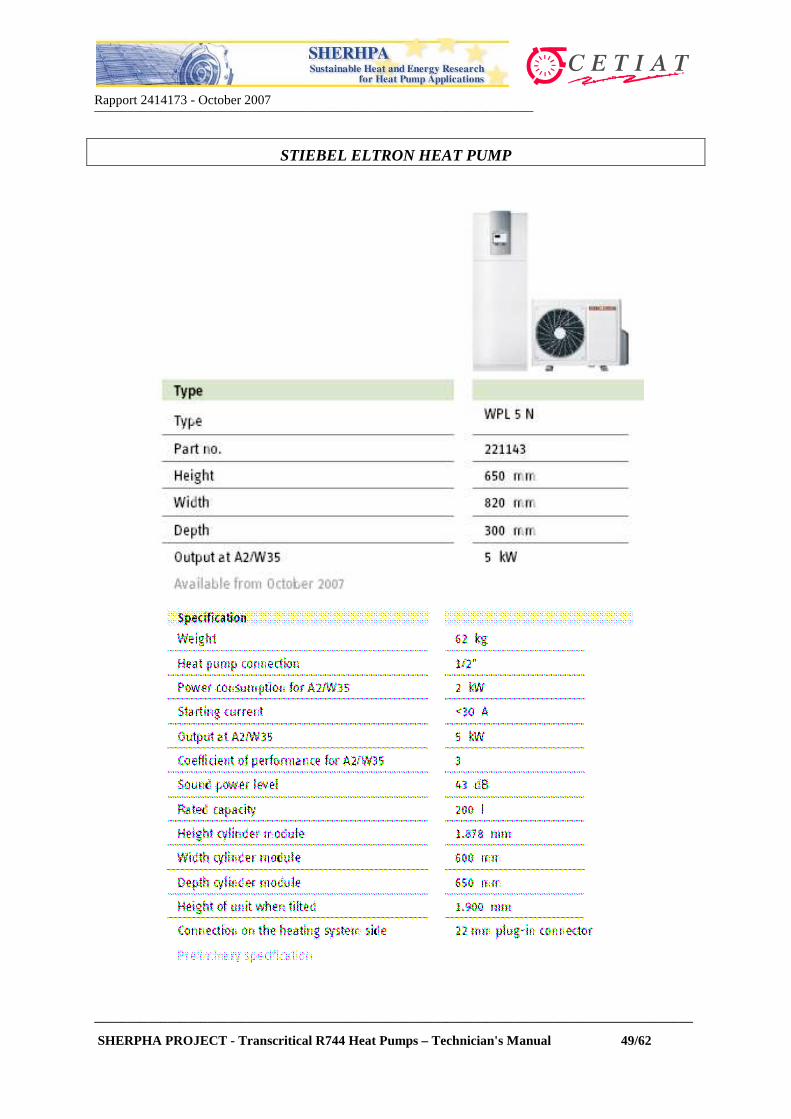
In Europe, a 5 kW heat pump with features similar to that of the Ecocute unit is marketed by
Stiebel Eltron. Annex 1 shows a brochure relevant to the "Compact series 5 kW" from this
manufacturer and from CTC, a Sweden-based manufacturer which proposes similar heat
pumps.
Annex 1 also shows excerpts of Instruction Manuals from Ecocute manufacturers. Residential
Ecocute units yield heating duties of the order of 4.5 kW. Japanese manufacturers claim to
have produced a million Ecocute units up to year 2007 (cumulated).
Some larger capacity R744 heat pumps are under development, targeting the commercial
market. The simplest models use two small domestic Ecocute units in series for water and
space heating (see example in Figure 11). Some Japanese manufacturers also market larger
units aiming industrial and large residential applications (hotels, hospitals, cafeterias etc).
Figure 12 shows an Itomic system installed on a building roof. It uses a large water capacity
(6 times 500 l). Figure 13 shows the water and R744 circuits.
Figure 12 : Large Ecocute systems from Itomic (www.itomic.co.jp)

Rapport 2414173 - October 2007__________________________________________________________________
__________________________________________________________________________________________
SHERPHA PROJECT - Transcritical R744 Heat Pumps – Technician's Manual 22/62
Figure 13 : Flow diagram of Ecocute from Itomic (www.itomic.co.jp)
3.2. Green and Cool Chiller Systems
Green and Cool are Swedish manufactured refrigeration and air conditioning units using
R744, for high, medium and low temperatures applications.
Figure 14 : Atlantic chiller front view Figure 15 : Side view 1

Rapport 2414173 - October 2007__________________________________________________________________
__________________________________________________________________________________________
SHERPHA PROJECT - Transcritical R744 Heat Pumps – Technician's Manual 23/62
These chillers can be operated either under sub-critical or transcritical conditions. Figures 12
to 15 show pictures of an "Atlantic" chiller.
Figures 12 and 13 show the control panel, the compressor rack (3 black units) and the R744
high pressure tanks (in green).
Figure 16 : Atlantic chiller back view Figure 17 : Side view 2
Annex 2 shows the Green and Cool "Atlantic" product range with a performance table. The
Atlantic product range is normally equipped with air-cooled gas cooler (not shown in Figures
12 to 15), and can handle duties up to 200 kW, depending on the evaporating temperature.
Green and Cool sources finned coils (gas coolers) from other manufacturers.
The Green and Cool Atlantic is a liquid chiller unit that is available as an air conditioning
unit (HT), a chiller unit (MT) and a freezer unit (LT) with a partially indirect system.
On the cold side the HT uses water for air conditioning, the MT uses 37% Propylene glycol
solution for chilling applications and and the LT uses R744 as the heat transfer medium for
freeze units.
3.3. Vending machines and bottle coolers
Transcritical R744 cycles are also used for small commercial refrigeration systems. The Coca
Cola Company (TCCC) has pledged to reduce to the lowest possible its uses of synthetic
refrigerants. As of year 2007, they operate 6000 transcritical vending machines with duties
ranging from 300 W to a few kW.

Rapport 2414173 - October 2007__________________________________________________________________
__________________________________________________________________________________________
SHERPHA PROJECT - Transcritical R744 Heat Pumps – Technician's Manual 24/62
Figures 18 and 19 show the cassette type refrigeration system working with R744. Figure 20
shows the product range potentially covered by transcritical cycles.
Figure 18 : R744 cycle components Figure 19 : R744 Cooling cassette
Figure 20 : Coca-Coal vending machines range of products
Rapport 2414173 - October 2007__________________________________________________________________
__________________________________________________________________________________________
SHERPHA PROJECT - Transcritical R744 Heat Pumps – Technician's Manual 25/62
4. COMPONENTS FOR R744 HEAT PUMPS
Components for R744 systems have to withstand much higher pressures than their HFC and
HCFC counterparts. Pressure differentials are higher by one order of magnitude. Other issues
are introduced by the particularity of R744, e.g. high discharge temperatures, compatibility
with lubricating oils, potential degradation of seals after decompression, etc. These issues
hinder the fast development of a "component chain".
In Japan, the mostly available components for transcritical cycles are those used in the
Ecocute systems, viz. air coils (evaporators), compressors, electronic expansion valves
(EEVs) and water-to-R744 heat exchangers ("gas coolers"). In Europe, few manufacturers
have an offer for R744 components, except Danfoss, which mainly markets compressors, and
valves.
In this section, we will examine the marketed items (or to-be-marketed as claimed by
component manufacturers), and describe their respective technologies.
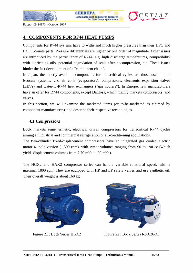
4.1. Compressors
Bock markets semi-hermetic, electrical driven compressors for transcritical R744 cycles
aiming at industrial and commercial refrigeration or air-conditioning applications.
The two-cylinder fixed-displacement compressors have an integrated gas cooled electric
motor 4- pole version (1,500 rpm), with swept volumes ranging from 90 to 190 cc (which
yields displacement volumes from 7.70 m³/h to 20 m³/h).
The HGX2 and HAX2 compressor series can handle variable rotational speed, with a
maximal 1800 rpm. They are equipped with HP and LP safety valves and use synthetic oil.
Their overall weight is about 160 kg.
Figure 21 : Bock Series HGX2 Figure 22 : Bock Series RKX26/31

Rapport 2414173 - October 2007__________________________________________________________________
__________________________________________________________________________________________
SHERPHA PROJECT - Transcritical R744 Heat Pumps – Technician's Manual 26/62
The RKX26/31 semihermetic compressor takes advantage of a new design with 6 radial
pistons. This enable a slimmer version than the HGX2 series. The motor is gas cooled in 2 or
4- pole version (3000/1500 rpm – maximum speed of 3600 rpm). With a swept volume of 31
cc, it enables a displacement volume of 2.60 m³/hr to 6.70 m³/h. This compressor can be
mounted both in horizontal and vertical positions. It uses Bock C120E (Synthetic Oil), has an
integrated oil separator and HP/LP safety valves.
Danfoss offers small displacement volume
compressors (see Figure 23), with capacity
ranging from about 500 W to 2 kW. Figure 24
shows the claimed performance for the product
range. The size is about the same as those used
in domestic refrigerators, i.e. from 1 to 3 cc
displacement volume. These compressors are
used in some of the Coca Cola vending
machines refrigeration cassettes.
Figure 23 : Danfoss R744 compressor
(www.danfoss.com)
Figure 24 : Danfoss compressors characteristics

Rapport 2414173 - October 2007__________________________________________________________________
__________________________________________________________________________________________
SHERPHA PROJECT - Transcritical R744 Heat Pumps – Technician's Manual 27/62
The Brazilian manufacturer Embraco makes
reciprocating compressors (see Figure 25)
with displacement volumes that are within the
same range as the Danfoss series (1 to 3 cc).
Figure 26 shows the claimed (refrigeration)
performance for these compressors. For heat
pumps, the Embraco range of compressors
enable a maximum heating duty of about 2.7
kW at 50 Hz.
Figure 25 : Embraco R744 compressor
Figure 26 : Embraco R744 compressor product line
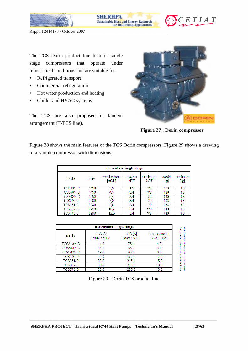
The Italian manufacturer Dorin markets a range of compressors for transcritical operation.
With displacement volumes from 3.5 to 12.6 m3/hr, Dorin covers the largest range of duties
available on the market.
Rapport 2414173 - October 2007__________________________________________________________________
__________________________________________________________________________________________
SHERPHA PROJECT - Transcritical R744 Heat Pumps – Technician's Manual 28/62
The TCS Dorin product line features single
stage compressors that operate under
transcritical conditions and are suitable for :
• Refrigerated transport
• Commercial refrigeration
• Hot water production and heating
• Chiller and HVAC systems
The TCS are also proposed in tandem
arrangement (T-TCS line).
Figure 27 : Dorin compressor
Figure 28 shows the main features of the TCS Dorin compressors. Figure 29 shows a drawing
of a sample compressor with dimensions.
Figure 29 : Dorin TCS product line

Rapport 2414173 - October 2007__________________________________________________________________
__________________________________________________________________________________________
SHERPHA PROJECT - Transcritical R744 Heat Pumps – Technician's Manual 29/62
Figure 30 : Compressor dimensions
Standard compressors from Dorin are PED certified and equipped with:
• electric motors with thermistor protection
• oil pump and oil cooler : the oil temperature is controlled so as to remain within the 30 to
65°C range in order to reduce oil carry-over and R744 solubility.
• low and high pressure relief valve with relieving set point of respectively 100 bar (Pss)
and 163 bar (PS)
• crankcase heater
• special lubricant for R744 transcritical application.
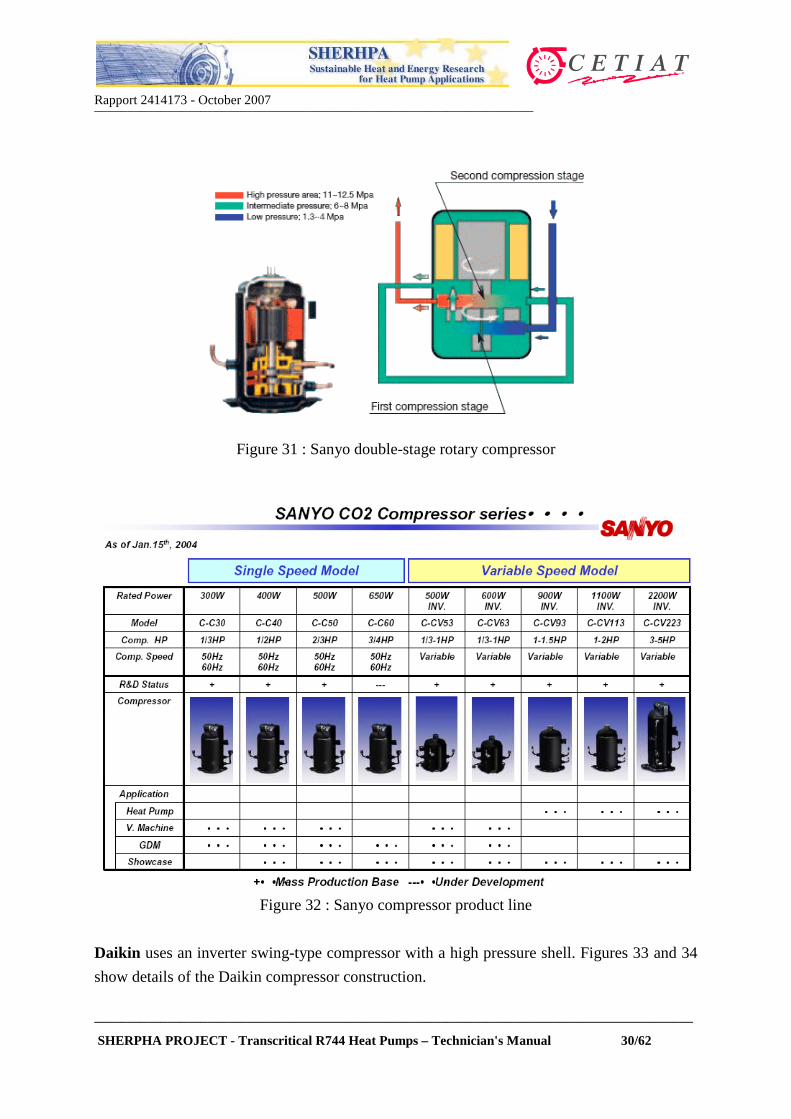
In Japan, all Ecocute manufacturers use their own, proprietary transcritical compressor, but
only Sanyo has a complete product line that is marketed independently of their Ecocute
model. These rotary, double-stage compressors are used in some of the Coca Cola vending
machines. The compressor shell is at the intermediate pressure, as shown by Figure 31.
Rapport 2414173 - October 2007__________________________________________________________________
__________________________________________________________________________________________
SHERPHA PROJECT - Transcritical R744 Heat Pumps – Technician's Manual 30/62
Figure 31 : Sanyo double-stage rotary compressor
Figure 32 : Sanyo compressor product line
Daikin uses an inverter swing-type compressor with a high pressure shell. Figures 33 and 34
show details of the Daikin compressor construction.

Rapport 2414173 - October 2007__________________________________________________________________
__________________________________________________________________________________________
SHERPHA PROJECT - Transcritical R744 Heat Pumps – Technician's Manual 31/62
Figure 33 : Daikin compressor Figure 34 : View of Daikin swing compressor
4.2. Evaporators
Heat pump evaporator technologies use either finned coils, plate-and-tube (air source), or
plate heat exchangers and shell-and-tube (for liquids).
Figure 35 : Daikin air-to-refrigerant evaporator with fan on Ecocute chassis
Rapport 2414173 - October 2007__________________________________________________________________
__________________________________________________________________________________________
SHERPHA PROJECT - Transcritical R744 Heat Pumps – Technician's Manual 32/62
Refrigerant-to-liquid plate heat exchangers are not available for pressures higher than about
40 bars, except for very costly, customized, industrial applications. Plate heat exchangers are
therefore not used in transcritical cycle because of the pressure constraints (as of 2007).
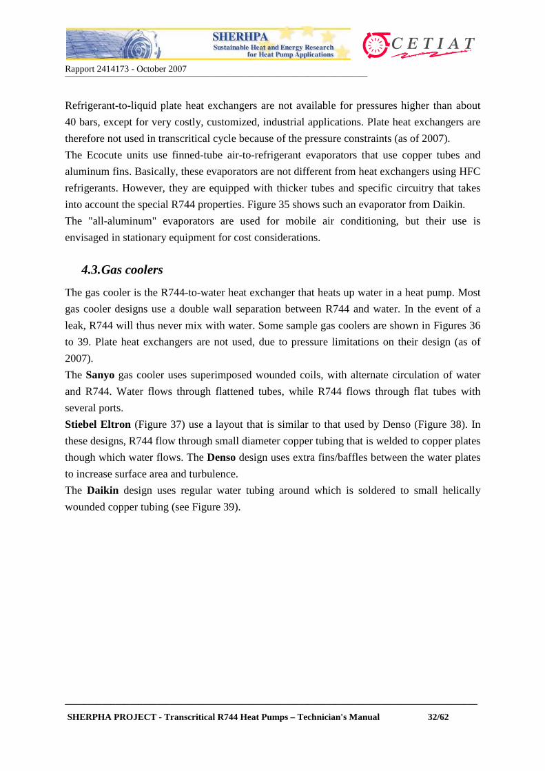
The Ecocute units use finned-tube air-to-refrigerant evaporators that use copper tubes and
aluminum fins. Basically, these evaporators are not different from heat exchangers using HFC
refrigerants. However, they are equipped with thicker tubes and specific circuitry that takes
into account the special R744 properties. Figure 35 shows such an evaporator from Daikin.
The "all-aluminum" evaporators are used for mobile air conditioning, but their use is
envisaged in stationary equipment for cost considerations.
4.3. Gas coolers
The gas cooler is the R744-to-water heat exchanger that heats up water in a heat pump. Most
gas cooler designs use a double wall separation between R744 and water. In the event of a
leak, R744 will thus never mix with water. Some sample gas coolers are shown in Figures 36
to 39. Plate heat exchangers are not used, due to pressure limitations on their design (as of
2007).
The Sanyo gas cooler uses superimposed wounded coils, with alternate circulation of water
and R744. Water flows through flattened tubes, while R744 flows through flat tubes with
several ports.
Stiebel Eltron (Figure 37) use a layout that is similar to that used by Denso (Figure 38). In
these designs, R744 flow through small diameter copper tubing that is welded to copper plates
though which water flows. The Denso design uses extra fins/baffles between the water plates
to increase surface area and turbulence.
The Daikin design uses regular water tubing around which is soldered to small helically
wounded copper tubing (see Figure 39).

Rapport 2414173 - October 2007__________________________________________________________________
__________________________________________________________________________________________
SHERPHA PROJECT - Transcritical R744 Heat Pumps – Technician's Manual 33/62
Figure 36 : Sanyo gas cooler Figure 37 : Stiebel Eltron gas cooler
Figure 38 : Denso gas cooler
Figure 39 : Daikin gas cooler

Rapport 2414173 - October 2007__________________________________________________________________
__________________________________________________________________________________________
SHERPHA PROJECT - Transcritical R744 Heat Pumps – Technician's Manual 34/62
4.4. Expansion devices and controls
Transcritical heat pumps require high pressure control to minimize power consumption, as
covered in Section 2.3. This optimal pressure is a function of evaporating pressure (or
temperature) and R744 gas cooler outlet temperature. Figure 40 shows the location of a
motorized control expansion valve, a solenoid valve (for defrost) and of a pressure sensor in a
typical Ecocute unit for hot water supply.
Figure 40 : Control valves and pressure sensor in an Ecocute unit
Figure 41 : Control valves and sensor from Saginomiya
The Ecocute units use electronic valves from Saginomiya, as shown in Figure 41. Electronic
expansion valves that use information from operating parameters (water or R744 outlet

Rapport 2414173 - October 2007__________________________________________________________________
__________________________________________________________________________________________
SHERPHA PROJECT - Transcritical R744 Heat Pumps – Technician's Manual 35/62
temperature from the gas cooler, evaporating temperature or air outdoors temperature)
provide the best control system. These controls are implemented in the Ecocute unit and the
Stiebel Eltron heat pump.
If transcritical operation at fixed pressure is possible, Danfoss proposes two pressure
regulators:
• A manual pressure regulator – the pressure can be set manually on the valve (MBR);
• An automatic back pressure regulator, which uses the gas cooler outlet temperature to
control high pressure (BPR)
Figure 42 : Danfoss MBR regulator for transcritical R744 systems
These two valves are shown in Figures 442 and 43.

Rapport 2414173 - October 2007__________________________________________________________________
__________________________________________________________________________________________
SHERPHA PROJECT - Transcritical R744 Heat Pumps – Technician's Manual 36/62
Figure 43 : Danfoss TBR regulator for transcritical R744 systems
For large transcritical refrigeration duties, Danfoss markets an expansion valve for pressure
control (see Figure 44).
Figure 44 : Danfoss pressure control/expansion valve for larger duty transcritical systems

Rapport 2414173 - October 2007__________________________________________________________________
__________________________________________________________________________________________
SHERPHA PROJECT - Transcritical R744 Heat Pumps – Technician's Manual 37/62
5. SAFETY GUIDELINES WHEN USING R744 IN HEAT PUMPS
Section 2.1 provided some basic physical and thermodynamic data of R744 that were used as
background information to understand the transcritical cycle operation. This Section will
provide more information and safety guidelines regarding the practical use of this refrigerant.
Annex 3 contains a Safety Data Sheet from a main R744 producer which should consulted
for safety precautions for this refrigerant.
Transcritical heat pumps are not fundamentally different from subcritical heat pumps. Hence
all usual, basic safety precautions taken for the operation of conventional heat pumps
equally apply to R744 heat pumps. Some additional rules will be introduced by the
transcritical cycle distinct features, which are the higher operating pressures and temperatures,
the specific control schemes and the use of R744 as a refrigerant.
5.1. R744 effects on health
Gaseous R744 is colorless and odorless at low concentrations.
It is not flammable. It is stable under normal conditions but
can become dangerous if inhaled at concentrations roughly
around 2%. Due to the fact that it is odorless, it is not self-
alarming in case of leaks from systems.
Table 4 summarizes the effects and symptoms related to R744
inhalation depending on its concentration in the air.
Table 4 : Effects of R744 on human health
Conc. in air Effects and Symptoms2% 50% increase in breathing rate3% 10 Minutes short term exposure limit; 100% increase in breathing rate
5%300% increase in breathing rate, headache and sweating may begin after about an hour (Com.: this will tolerated by most persons, but it is physical burdening)
8% Short time exposure limit
8-10% Headache after 10 or 15 minutes. Dizziness, buzzing in the ears, blood pressure increase, high pulse rate, excitation, and nausea.
10-18% After a few minutes, cramps similar to epileptic fits, loss of consciousness, and shock (i.e.; a sharp drop in blood pressure) The victims recover very quickly in fresh air.
18-20% Symptoms similar those of a stroke
Note that with a relative density of 1.53, R744 is heavier than air; thus, it tends to concentrate
near the ground level when spilled.

Rapport 2414173 - October 2007__________________________________________________________________
__________________________________________________________________________________________
SHERPHA PROJECT - Transcritical R744 Heat Pumps – Technician's Manual 38/62
Air-source heat pumps are always installed outdoors – that is where they pick up heat. Since
connecting pipework between the heat pump and the hydraulic system contains only water,
and because of the double-wall separating water and R744 in the water heater, there is no
possibility of leakage of R744 in the water circuit.
A water-source heat pump can be installed indoors. Installation should be carried out
correctly to avoid accumulation of R744 in specific locations should a leak occur:
• Ventilation must be provided. Avoid working with R744 where it can be collect in low or
confined areas.
• Do not remain near the heat pump in the event of a large carbon dioxide release. Before
returning to the premises, make sure that the R744-concentration is low enough. The
R744 concentration can be analyzed with specific sensors.
• R744 containers must stand upright when gas is being withdrawn. Cold R744 can form a
very thick mist with moist air.
• Persons who succumb to R744 poisoning must be taken into the open air quickly.
Artificial respiration should be administered if the victims stop breathing
5.2. R744 in heat pumps
5.2.1. Pressure at standstill
Because of their high value of critical temperature, the pressure at standstill (i.e. when the
system is shut-down) for conventional refrigerants is a function of ambient temperature
(assuming the system temperature has reached that value). Even under severe ambient
temperatures, most HFC/HCFC refrigerants systems exhibit pressures lower than 40 bars at
standstill.
For R744, the standstill pressure evolves as follows :
• For ambient temperatures under 31°C, the pressure is equal to that above the vapor phase,
i.e. the standstill pressure is equal to the saturation pressure of R744. At a temperature of
31°C, this pressure reaches about 75 bars.
• For ambient temperatures above 31°C, all the R744 contained in the system is under
"supercritical" conditions. Thus, the standstill pressure is above 75 bars, but depends on
the ambient temperature, the mass of R744 charged into the system and the internal
volume of the system.
Rapport 2414173 - October 2007__________________________________________________________________
__________________________________________________________________________________________
SHERPHA PROJECT - Transcritical R744 Heat Pumps – Technician's Manual 39/62
5.2.2. Operating temperatures and pressures
For ambient temperatures of about 7°C, typical pressures for air source heat pumps under
operation are as follows :
• Low pressure side : pressures between 25 and 50 bars and evaporating temperature
between –12°C and 20°C. Under lower ambient temperatures, these values may be lower.
• High pressure side : pressures between 90 and 130 bars, temperatures between 90 and
130°C.
Refrigerant piping on the high pressure side will be therefore very hot and will cause burning.
Direct contact must be avoided when the unit is operating or has just been shut down.
5.2.3. Material compatibility
The information contained in Table 5 has been compiled from Air Liquide (sources :
International Standards: Compatibility of cylinder and valve materials with gas content; Part
1: ISO 11114-1 (Jul 1998), Part 2: ISO 11114-2 (Mar 2001)), and must be used with extreme
caution.
No raw data such as this can cover all conditions of concentration, temperature, humidity,
impurities and aeration. It is therefore recommended that this table be used to choose possible
materials and then more extensive investigation and testing is carried out under the specific
conditions of use. The collected data mainly concern high pressure applications at ambient
temperature and the safety aspect of material compatibility rather than the quality aspect.

Rapport 2414173 - October 2007__________________________________________________________________
__________________________________________________________________________________________
SHERPHA PROJECT - Transcritical R744 Heat Pumps – Technician's Manual 40/62
Table 5 : R744 compatibility with materialsMaterial Compatibility
Aluminium SatisfactoryBrass SatisfactoryCopper Satisfactory
Ferritic Steels (e.g. Carbon steels)Satisfactory but risk of corrosion in presence of CO and/or moisture, Cold brittleness.
Stainless Steel Satisfactory
Polytetrafluoroethylene (PTFE) SatisfactoryPolychlorotrifluoroethylene (PCTFE) SatisfactoryVinylidene polyfluoride(PVDF) (KYNAR™) SatisfactoryPolyamide(PA) (NYLON™) SatisfactoryPolypropylene(PP) Satisfactory
Buthyl (isobutene - isoprene) rubber (IIR) Non recommended, significant swelling.
Nitrile rubber (NBR)Non recommended, significant swelling and significant loss of mass by extraction or chemical reaction.
Chloroprene (CR)Non recommended, significant swelling and significant loss of mass by extraction or chemical reaction.
Chlorofluorocarbons (FKM) (VITON™)Non recommended, significant swelling and significant loss of mass by extraction or chemical reaction.
Silicon (Q) Acceptable but strong rate of permeation.
Ethylene-Propylene (EPDM)Acceptable but important swelling and significant loss of mass by extraction or chemical reaction.
Hydrocarbon based lubricant SatisfactoryFluorocarbon based lubricant Satisfactory
Metals
Plastics
Elastomers
Lubricants
5.2.4. Water and R744
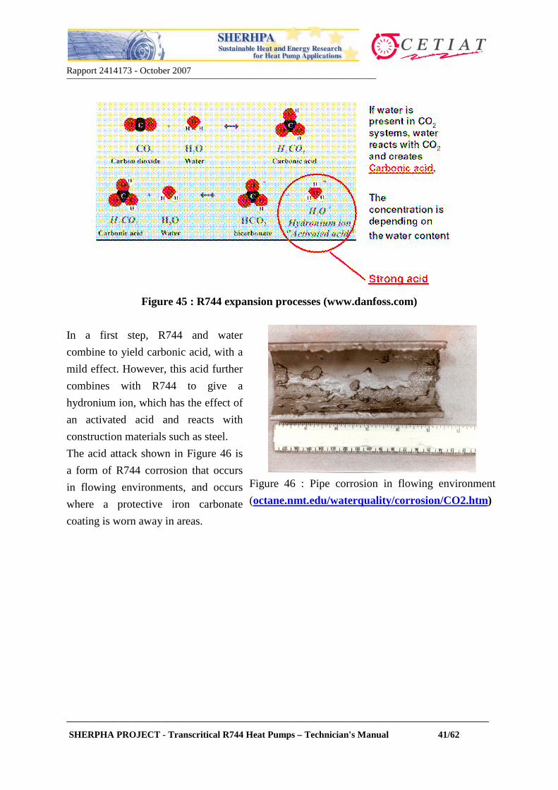
Figure 45 (from Danfoss technical literature) shows what the combination of water and R744
leads to.
Rapport 2414173 - October 2007__________________________________________________________________
__________________________________________________________________________________________
SHERPHA PROJECT - Transcritical R744 Heat Pumps – Technician's Manual 41/62
Figure 45 : R744 expansion processes (www.danfoss.com)
In a first step, R744 and water
combine to yield carbonic acid, with a
mild effect. However, this acid further
combines with R744 to give a
hydronium ion, which has the effect of
an activated acid and reacts with
construction materials such as steel.
The acid attack shown in Figure 46 is
a form of R744 corrosion that occurs
in flowing environments, and occurs
where a protective iron carbonate
coating is worn away in areas.
Figure 46 : Pipe corrosion in flowing environment
(octane.nmt.edu/waterquality/corrosion/CO2.htm)

Rapport 2414173 - October 2007__________________________________________________________________
__________________________________________________________________________________________
SHERPHA PROJECT - Transcritical R744 Heat Pumps – Technician's Manual 42/62
With very high concentration of water
in R744 systems, the R744 gas hydrate
can be formed. The R744 gas hydrate
(see Figure 47) looks like ice, but
exists also at higher temperatures than
0°C. The CO2 gas hydrate can create
problem, e.g. plugging filters and
pipes.
Figure 47 : R744 gas hydrates (www.danfoss.com)
Water can also enter the system via the lubricant oil. With synthetic mineral oil such as Poly-
Alpha-Olefin lubricant oil, oxygen (generated by corrosion for example) reacts and yields
water and a strong organic acid. This acid in turn reacts on construction materials.
Figure 48 : Effect of oxygen on mineral oil (www.danfoss.com)
With ester oil, free water combines to form an alcohol and a relatively weak acid (see Figure
48). However, when these reaction products are carried around in the refrigeration system,
high temperatures will be encountered, with an amplification of the acidic effects.
Figure 49 : Effect of water on ester oil (www.danfoss.com)

Rapport 2414173 - October 2007__________________________________________________________________
__________________________________________________________________________________________
SHERPHA PROJECT - Transcritical R744 Heat Pumps – Technician's Manual 43/62
Water can enter the system mainly because of the following reasons :
• Incomplete water removal during installation / commissioning;
• Water-contaminated lubricant charged into the system;
• Water-contaminated CO2 charged into the system.
It is therefore very important to avoid water contamination through good service practices :
• Thoroughly vacuum systems (same procedure and duration as HCFC/HFC refrigerants;
• Avoid letting oil cans open – always put the cap back to avoid water contamination of oil;
• Avoid letting the circuit open to the air during servicing when not required – always
remove caps or bolts just before welding/tightening;
• Change filter/dryer cartridge upon servicing.
6. SERVICING AND MAINTENANCE ASPECTS
This Section attempts to explain the fundamentals of R744 behavior and its consequences on
the Servicing and Maintenance aspects of R744 heat pumps.
R744 heat pumps must be treated as "hot water heaters". In particular, the refrigerant circuit is
tuned in the factory and should therefore not be tampered with, except by fully authorized
personnel. Note that Annex 1 contains information material from an Ecocute manufacturer.
Consult this Annex for further advice on how to handle such heat pumps.
6.1.1. Evacuating R744 : the expansion process
Upon expansion, refrigerants tend to cool. R744 possesses a high triple point around –56°C
and 5.2 bars. Therefore, care must be taken to avoid sudden pressure release that would bring
it to solid state, or any expansion process which could lead to such a state. Figure 50
illustrates the R744 expansion processes from different pressure levels:
• Expanding vapor from point C (35 bars) to the triple point pressure will result first in the
partial vaporization of R744, and will then lead to gaseous state.
• Expanding vapor from point B (50 bars) will lead to a 5% of the refrigerant in solid state
("dry ice") at the triple point pressure.
• Expanding liquid from any pressure (e.g. point A at 20 bars) will lead to a substantial
amount of R744 dry ice in the equipment. This also occurs when the expansion process
starts from other higher pressures, e.g. higher saturation temperatures.

Rapport 2414173 - October 2007__________________________________________________________________
__________________________________________________________________________________________
SHERPHA PROJECT - Transcritical R744 Heat Pumps – Technician's Manual 44/62
A
B C
Figure 50 : R744 expansion processes
As a rule of thumb, the expansion of liquid R744 from any pressure level, and the
expansion of gaseous R744 from a pressure higher than 35 bars will lead to the formation
of dry ice if the final pressure is lower than about 5.2 bars. This specific behavior should be
borne in mind, for example when discharging R744 from systems.
As of year 2007, there is no obligation to recover R744 from refrigeration/heat pump systems.
Hence, R744 can be discharged to the atmosphere.
In the event of a R744 release from the heat pump via a safety valve or when discharging
R744 from a system, care must be taken not to deteriorate equipment by dry ice. In particular,
when evacuating R744, avoid pipe lengths that could be plugged by dry ice formation due to
pressure expansion.
6.1.2. Recharging R744 heat pumps
When servicing heat pumps, refrigerant recharging for conventional refrigerants (HFCs and
HCFCs) is carried out using the value of nominal charge and the following information:
• the values of high pressure and subcooling after the condenser and/or superheat at
compressor suction;
• the refrigerant state before expansion (view through a liquid line sight glass, when
available).
Rapport 2414173 - October 2007__________________________________________________________________
__________________________________________________________________________________________
SHERPHA PROJECT - Transcritical R744 Heat Pumps – Technician's Manual 45/62
Transcritical R744 heat pumps are fundamentally different because:
• there is no distinction between liquid and vapor phase before expansion;
• there is no value of "subcooling" after the gas cooling process – because subcooling does
not exist as such;
• the relationship between high pressure and refrigerant charge in the system is more
complex than for conventional refrigerants.
Transcritical R744 domestic systems are normally factory-charged. The refrigerant charge has
numerous effects, particularly on the value of the compressor discharge pressure.
Inappropriate refrigerant charge could thus lead to improper heat pump operation and/or
equipment damage. This explains why most residential heat pumps are only serviced in the
manufacturer workshop or at an authorized service station.
Thus, any attempt to recharge R744 heat pumps should not be made, unless it is authorized
by the manufacturer. Recharging a R744 system can only by carried out if full and explicit
instructions are provided by the heat pump manufacturer.
Annex 1, which shows excerpts from an Ecocute Service Manual issues important warnings
against attempts to recharge the unit.
Systems using R744 must be thoroughly evacuated like conventional refrigeration systems.
Before any servicing, make sure that all the following is available to carry out refrigerant
recharging :
• Instructions from the manufacturer, including required information, e.g. the total amount
of refrigerant for recharge.
• Components required, e.g. filter/driers for R744 and suitable for the required design
operating pressures should be used.
• Appropriate recharging station if specified by manufacturer.
Recharging R744 systems like conventional systems is not readily possible. With HFC
refrigerants and other systems it is common practice to recharge liquid via the liquid line upon
completion of the evacuation i.e. when the plant is still under vacuum. This is not possible
with an R744 system because dry ice would form internally at the charging point when the
system pressure is less than around 6 bar, because of expansion (see Section 6.1.1).
Before charging liquid R744 into the system on the high pressure side, it is therefore
necessary to increase the system pressure to a level of about 6 bar using gaseous R744.

Rapport 2414173 - October 2007__________________________________________________________________
__________________________________________________________________________________________
SHERPHA PROJECT - Transcritical R744 Heat Pumps – Technician's Manual 46/62
Once this value is reached, recharging may proceed with liquid R744. The correct system
charge must be known from the Service Manual. Do not attempt to charge an R744 system
when the amount of refrigerant charge is unknown. This may lead to system overcharge and
to high pressure increase.
6.1.3. R744 containers and recharge system
Refrigerant R744 is available in pressurized cylinders with contents ranging from about 3 to
35 kg. R744 is produced by chemical companies such as Linde Gas, Air Liquide and Praxair.
Cylinders are made of steel or aluminum, with a service pressure between 125 and 200 bars.
Linde Gas available cylinders are listed in Table 6. The first column indicates the cylinder
reference and the second column the R744 net content. The equivalent volume in gaseous
form at 1 atm and ambient conditions is shown in the third column.
Assuming a workshop with a width of 4 m, a length of 10 m and a height of 3 m, the last
column shows the air R744 concentration in the air (in percent), should the entire cylinder
spill into the room.
Table 6 : Linde Gas R744 pressurized cylinders
Cylinder R744 (kg) m3 @ 1 atm/20°C % in air in 120 m3 workshopMini 3.7 1.88 1.6B20 15 7.64 6.4B30 22 11.20 9.3B33 25 12.73 10.6B40 30 15.27 12.7B47 34.5 17.56 14.6
Table 6 shows that cylinder B30 reaches the lethal limit of 9%. However, the calculation
shown in Table 6 assumes a uniform spread throughout the workshop. Since R744 is heavier
than air (relative density of 1.52), it will stagnate in lower parts. Thus, even spills from
cylinders B20 and B30 can be dangerous. Spills from the "mini" cylinder can cause health
problems (see Table 4). It is therefore recommended to store R744 cylinders in ventilated
areas.
If R744 is charged directly from the cylinder into the system (with compressor being shut-
down), the following will happen :

Rapport 2414173 - October 2007__________________________________________________________________
__________________________________________________________________________________________
SHERPHA PROJECT - Transcritical R744 Heat Pumps – Technician's Manual 47/62
• the cylinder pressure will progressively decrease. After a small number of recharges, the
cylinder pressure decreases. It will not be sufficient to charge refrigerant when the system
pressure reaches the R744 vapor pressure; the cylinder will not be fully exploited and part
of refrigerant will be left in the cylinder and wasted.
• the efficiency of charging operation depends on the pressure in the cylinder, and thus on
the ambient temperature.
In a workshop, it is recommended to use a charging station that is suitable for R744
refrigerant. This station (see Figure 51 and 52) will enable fine charge tuning and full cylinder
exploitation.
Figure 51 : Charging station for R744 refrigerant
Figure 52 : R744 charging system (www.agramkow.dk)

Rapport 2414173 - October 2007__________________________________________________________________
__________________________________________________________________________________________
SHERPHA PROJECT - Transcritical R744 Heat Pumps – Technician's Manual 48/62
ANNEX 1 : INFORMATION ON MARKETEDDOMESTIC HEAT PUMPS
STIEBEL ELTRON HEAT PUMP
Rapport 2414173 - October 2007__________________________________________________________________
__________________________________________________________________________________________
SHERPHA PROJECT - Transcritical R744 Heat Pumps – Technician's Manual 49/62
STIEBEL ELTRON HEAT PUMP

Rapport 2414173 - October 2007__________________________________________________________________
__________________________________________________________________________________________
SHERPHA PROJECT - Transcritical R744 Heat Pumps – Technician's Manual 50/62
CTC AIR-TO-WATER HEAT PUMPS
Air-to-water R744 heat pumps from CTC (http://www.ctc-heating.com)

Rapport 2414173 - October 2007__________________________________________________________________
__________________________________________________________________________________________
SHERPHA PROJECT - Transcritical R744 Heat Pumps – Technician's Manual 51/62
EXCERPTS FROM SANYO ECOCUTE SERVICE MANUAL

Rapport 2414173 - October 2007__________________________________________________________________
__________________________________________________________________________________________
SHERPHA PROJECT - Transcritical R744 Heat Pumps – Technician's Manual 52/62
EXCERPTS FROM SANYO ECOCUTE SERVICE MANUAL

Rapport 2414173 - October 2007__________________________________________________________________
__________________________________________________________________________________________
SHERPHA PROJECT - Transcritical R744 Heat Pumps – Technician's Manual 53/62
EXCERPTS FROM SANYO ECOCUTE SERVICE MANUAL

Rapport 2414173 - October 2007__________________________________________________________________
__________________________________________________________________________________________
SHERPHA PROJECT - Transcritical R744 Heat Pumps – Technician's Manual 54/62
EXCERPTS FROM SANYO ECOCUTE SERVICE MANUAL

Rapport 2414173 - October 2007__________________________________________________________________
__________________________________________________________________________________________
SHERPHA PROJECT - Transcritical R744 Heat Pumps – Technician's Manual 55/62
EXCERPTS FROM SANYO ECOCUTE SERVICE MANUAL

Rapport 2414173 - October 2007__________________________________________________________________
__________________________________________________________________________________________
SHERPHA PROJECT - Transcritical R744 Heat Pumps – Technician's Manual 56/62
ANNEX 2 : CHILLERS
GREEN AND COOL PRODUCTS

Rapport 2414173 - October 2007__________________________________________________________________
__________________________________________________________________________________________
SHERPHA PROJECT - Transcritical R744 Heat Pumps – Technician's Manual 57/62
GREEN AND COOL PRODUCTS

Rapport 2414173 - October 2007__________________________________________________________________
__________________________________________________________________________________________
SHERPHA PROJECT - Transcritical R744 Heat Pumps – Technician's Manual 58/62
ANNEX 3 : SAFETY DATA SHEET

Rapport 2414173 - October 2007__________________________________________________________________
__________________________________________________________________________________________
SHERPHA PROJECT - Transcritical R744 Heat Pumps – Technician's Manual 59/62

Rapport 2414173 - October 2007__________________________________________________________________
__________________________________________________________________________________________
SHERPHA PROJECT - Transcritical R744 Heat Pumps – Technician's Manual 60/62

Rapport 2414173 - October 2007__________________________________________________________________
__________________________________________________________________________________________
SHERPHA PROJECT - Transcritical R744 Heat Pumps – Technician's Manual 61/62

Rapport 2414173 - October 2007__________________________________________________________________
__________________________________________________________________________________________
SHERPHA PROJECT - Transcritical R744 Heat Pumps – Technician's Manual 62/62
SELECTED REFERENCES
Further documents and information can be found from the following Internet web sites :
www.sherhpa.com
www.r744.com
www.danfoss.com
www.itomic.co.jp
www.sanyoaircon.com
www.heatpumpcentre.org
www.agramkow.dk
www.greenandcool.se
http://www.ctc-heating.com