Introduction to Receivers - TU Delftqtwork.tudelft.nl/~schouten/linkload/rfreceivers2.pdf · In a...
24
Introduction to Receivers • Purpose: translate RF signals to baseband – Shift frequency – Amplify – Filter – Demodulate • Why is this a challenge? – Interference (selectivity, images and distortion) – Large dynamic range required (SFDR) Many receivers must be capable of handling a very wide range of signal powers at the input while still producing the correct output. This must be done in the presence of noise and interference which occasionally can be much stronger than the desired signal. Noise sets the threshold for minimum detectable signal power - MDS Distortion sets the maximum signal power level. The third order input intercept (IIP3) is a figure of merit that is directly related to the intermodulation distortion produced by a particular design.
Transcript of Introduction to Receivers - TU Delftqtwork.tudelft.nl/~schouten/linkload/rfreceivers2.pdf · In a...

1
Introduction to Receivers
• Purpose: translate RF signals to baseband– Shift frequency– Amplify– Filter– Demodulate
• Why is this a challenge?– Interference (selectivity, images and distortion)– Large dynamic range required (SFDR)
Many receivers must be capable of handling a very wide range of signal powers at the input while still producing the correct output. This must be done in the presence of noise and interference which occasionally can be much stronger than the desired signal.
Noise sets the threshold for minimum detectable signal power - MDSDistortion sets the maximum signal power level. The third order input intercept (IIP3) is a figure of merit that is directly related to the intermodulation distortion produced by a particular design.

2
Power -174 dBm -130 dBm -80 dBm +10 dBm
4x10-21W 10-16W 10-11W 10-2W
Volts(rms)in 50Ω
0.6 nV 0.1µV 32µV 1V
Thermal noiseof resistor in1 Hz bandwidth
MDS forgood commreceiver in3 kHz BW
MDS forCell phone
Strong localsignal at inputof receiver
3
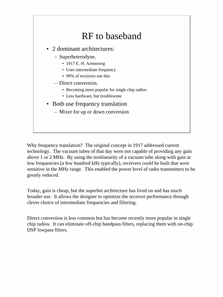
RF to baseband• 2 dominant architectures:
– Superheterodyne. • 1917 E. H. Armstrong• Uses intermediate frequency• 99% of receivers use this
– Direct conversion. • Becoming more popular for single chip radios• Less hardware, but troublesome
• Both use frequency translation– Mixer for up or down conversion
Why frequency translation? The original concept in 1917 addressed current technology. The vacuum tubes of that day were not capable of providing any gain above 1 or 2 MHz. By using the nonlinearity of a vacuum tube along with gain at low frequencies (a few hundred kHz typically), receivers could be built that were sensitive in the MHz range. This enabled the power level of radio transmitters to be greatly reduced.
Today, gain is cheap, but the superhet architecture has lived on and has much broader use. It allows the designer to optimize the receiver performance through clever choice of intermediate frequencies and filtering.
Direct conversion is less common but has become recently more popular in single chip radios. It can eliminate off-chip bandpass filters, replacing them with on-chip DSP lowpass filters.

4
Receiver block diagram
Front End Demodulation
antenna
fRF
fIF orfbaseband
Frequency translationAmplificationSelectivity
Audio, video, digital data,AM, FM, SSB, PSK, etc.
The front end of the receiver performs the frequency translation, channel selection and amplification of the signal.
5
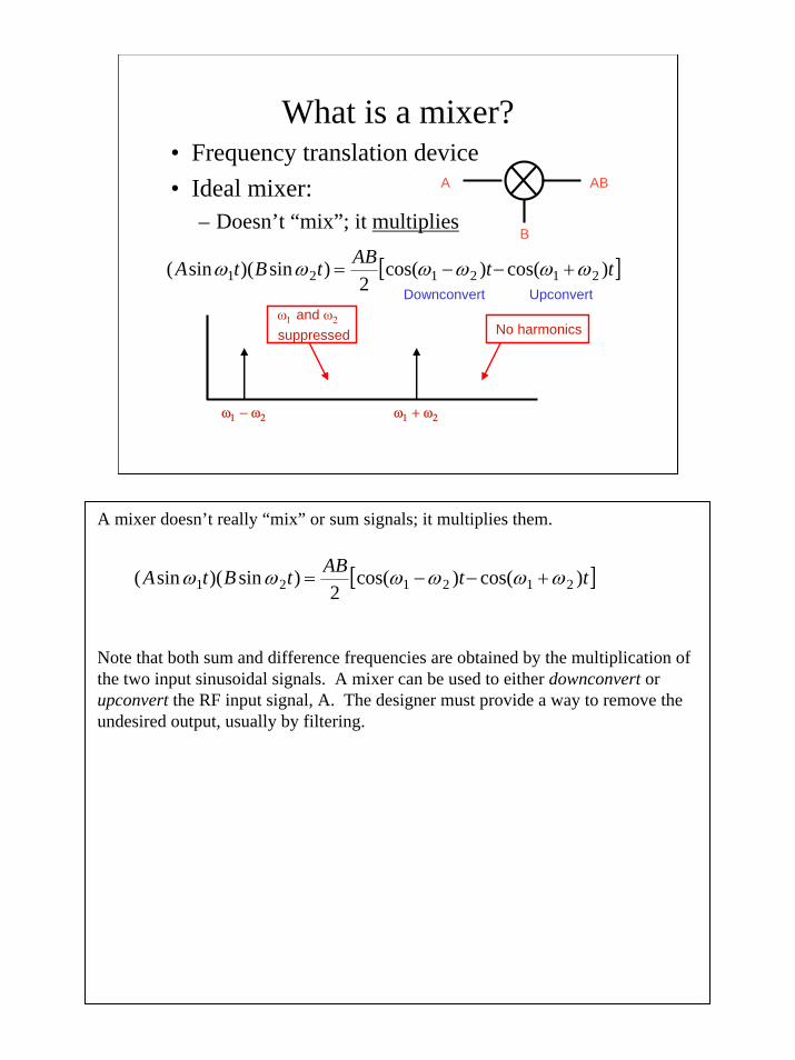
What is a mixer?• Frequency translation device• Ideal mixer:
– Doesn’t “mix”; it multiplies
A
B
AB
[ ]ttABtBtA )cos()cos(2
)sin)(sin( 212121 ωωωωωω +−−=Downconvert Upconvert
ω1 − ω2 ω1 + ω2
ω1 and ω2
suppressed No harmonics
A mixer doesn’t really “mix” or sum signals; it multiplies them.
Note that both sum and difference frequencies are obtained by the multiplication of the two input sinusoidal signals. A mixer can be used to either downconvert or upconvert the RF input signal, A. The designer must provide a way to remove the undesired output, usually by filtering.
[ ]ttABtBtA )cos()cos(2
)sin)(sin( 212121 ωωωωωω +−−=
6
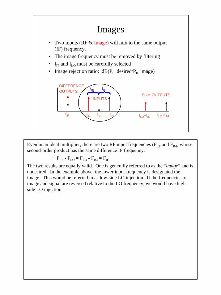
Images• Two inputs (RF & Image) will mix to the same output
(IF) frequency.• The image frequency must be removed by filtering• fIF and fLO must be carefully selected• Image rejection ratio: dB(PIF desired/PIF image)
fIF fRFfLOfIM
fIF fIF
fLO+fIM fLO+fRF
INPUTSSUM OUTPUTS
DIFFERENCEOUTPUTS
Even in an ideal multiplier, there are two RF input frequencies (FRF and FIM) whose second-order product has the same difference IF frequency.
FRF - FLO = FLO - FIM = FIF
The two results are equally valid. One is generally referred to as the “image” and is undesired. In the example above, the lower input frequency is designated the image. This would be referred to as low-side LO injection. If the frequencies of image and signal are reversed relative to the LO frequency, we would have high-side LO injection.
7
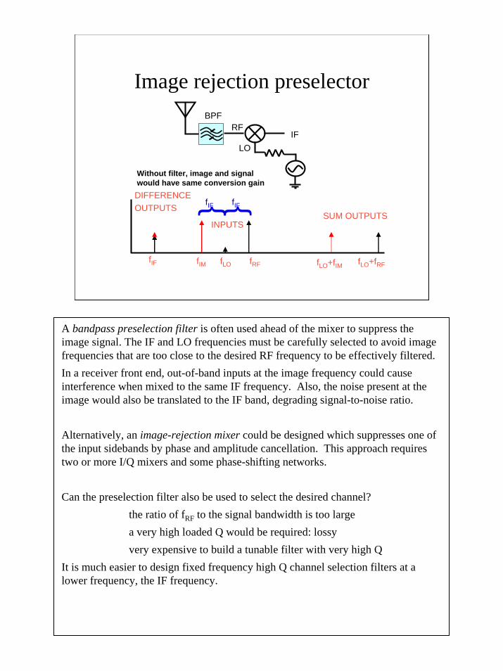
Image rejection preselector
fIF fRFfLOfIM
fIF fIF
fLO+fIM fLO+fRF
INPUTSSUM OUTPUTS
DIFFERENCEOUTPUTS
IFRF
LO
BPF
Without filter, image and signal would have same conversion gain
A bandpass preselection filter is often used ahead of the mixer to suppress the image signal. The IF and LO frequencies must be carefully selected to avoid image frequencies that are too close to the desired RF frequency to be effectively filtered. In a receiver front end, out-of-band inputs at the image frequency could cause interference when mixed to the same IF frequency. Also, the noise present at the image would also be translated to the IF band, degrading signal-to-noise ratio.
Alternatively, an image-rejection mixer could be designed which suppresses one of the input sidebands by phase and amplitude cancellation. This approach requires two or more I/Q mixers and some phase-shifting networks.
Can the preselection filter also be used to select the desired channel?the ratio of fRF to the signal bandwidth is too largea very high loaded Q would be required: lossyvery expensive to build a tunable filter with very high Q
It is much easier to design fixed frequency high Q channel selection filters at a lower frequency, the IF frequency.
8
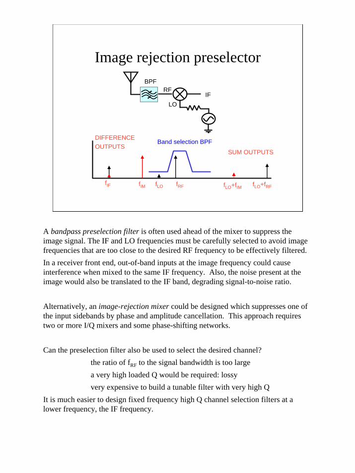
Image rejection preselector
fIF fRFfLOfIM
Band selection BPF
fLO+fIM fLO+fRF
SUM OUTPUTS
DIFFERENCEOUTPUTS
IFRF
LO
BPF
A bandpass preselection filter is often used ahead of the mixer to suppress the image signal. The IF and LO frequencies must be carefully selected to avoid image frequencies that are too close to the desired RF frequency to be effectively filtered. In a receiver front end, out-of-band inputs at the image frequency could cause interference when mixed to the same IF frequency. Also, the noise present at the image would also be translated to the IF band, degrading signal-to-noise ratio.
Alternatively, an image-rejection mixer could be designed which suppresses one of the input sidebands by phase and amplitude cancellation. This approach requires two or more I/Q mixers and some phase-shifting networks.
Can the preselection filter also be used to select the desired channel?the ratio of fRF to the signal bandwidth is too largea very high loaded Q would be required: lossyvery expensive to build a tunable filter with very high Q
It is much easier to design fixed frequency high Q channel selection filters at a lower frequency, the IF frequency.

9
Upconversion images
IFRF
LO
BPF
fLOfRF fIFfIM
In this case, even if there is only one signal at the input, fRF, there will be outputs from the mixer at:
FIF = FRF + FLO
FIM = FLO - FRF
The image is also frequency-reversed from the IF output.
Additional filtering or an image-rejecting mixer is needed to reduce this image frequency.
10
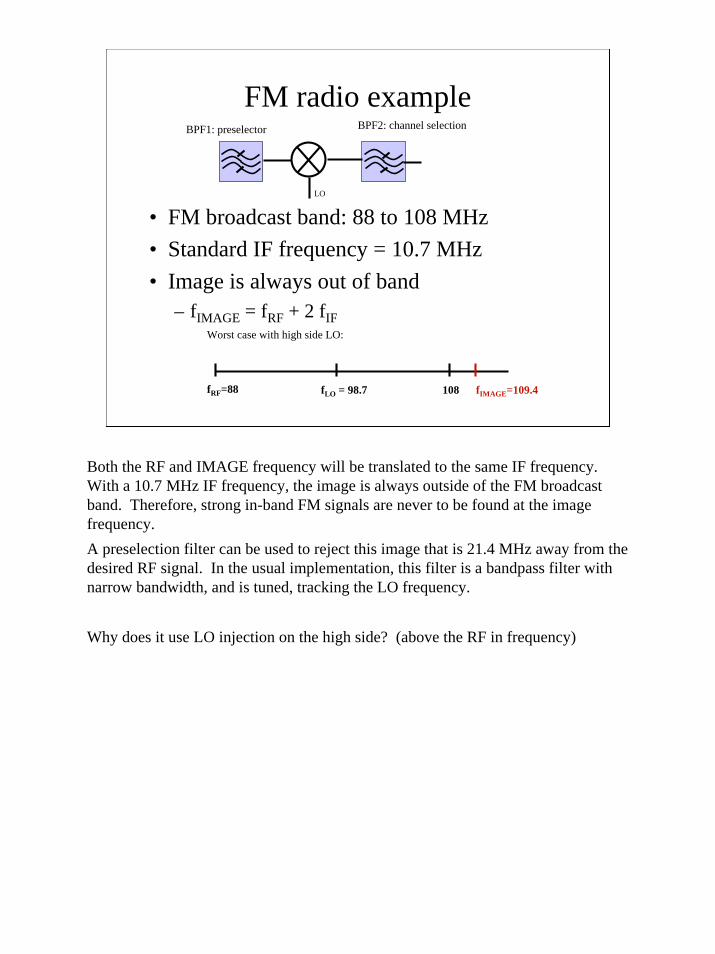
FM radio example
• FM broadcast band: 88 to 108 MHz• Standard IF frequency = 10.7 MHz• Image is always out of band
– fIMAGE = fRF + 2 fIF
fRF=88 108fLO = 98.7 fIMAGE=109.4
Worst case with high side LO:
LO
BPF1: preselector BPF2: channel selection
Both the RF and IMAGE frequency will be translated to the same IF frequency. With a 10.7 MHz IF frequency, the image is always outside of the FM broadcast band. Therefore, strong in-band FM signals are never to be found at the image frequency.A preselection filter can be used to reject this image that is 21.4 MHz away from the desired RF signal. In the usual implementation, this filter is a bandpass filter with narrow bandwidth, and is tuned, tracking the LO frequency.
Why does it use LO injection on the high side? (above the RF in frequency)
11
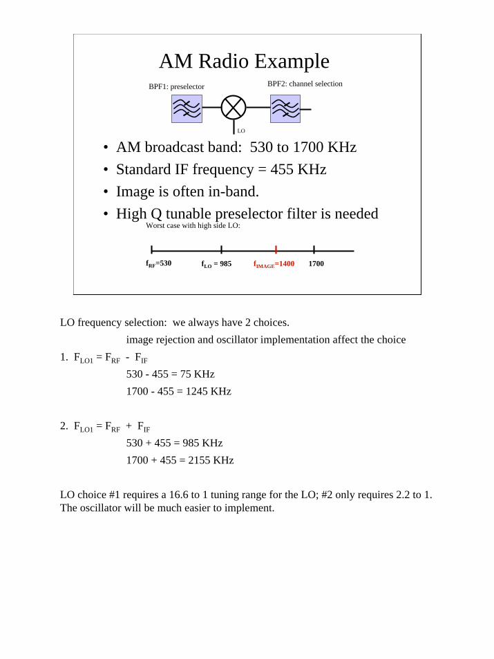
AM Radio Example
• AM broadcast band: 530 to 1700 KHz• Standard IF frequency = 455 KHz• Image is often in-band.• High Q tunable preselector filter is needed
fRF=530 1700fLO = 985 fIMAGE=1400
Worst case with high side LO:
LO
BPF1: preselector BPF2: channel selection
LO frequency selection: we always have 2 choices. image rejection and oscillator implementation affect the choice
1. FLO1 = FRF - FIF
530 - 455 = 75 KHz1700 - 455 = 1245 KHz
2. FLO1 = FRF + FIF
530 + 455 = 985 KHz1700 + 455 = 2155 KHz
LO choice #1 requires a 16.6 to 1 tuning range for the LO; #2 only requires 2.2 to 1. The oscillator will be much easier to implement.

12
What about image rejection?• With 455 KHz IF, image can be in-band.
– Potential interference problem– First BPF must be very selective and tunable
• Can we redesign the receiver to use fixed low-pass preselector?– Use higher FIF >> FRF.– Preselector admits entire AM band– No tuning allowed

13
LO
LPF1: preselector;Band selection
BPF2: channel selection
1700 KHz fIMAGE
Insertion loss
Image rejection
- X dB/decade slope
dB
log f
Let’s make the preselection filter simple and cheap: 2 poles give - 40 dB/decade. We will design according to two requirements:
minimum of 40 dB image rejection ratioinexpensive IF filter: try 10.7 MHz IF frequency
Let: fRF, min = 530 KHz. fIMAGE = fRF,min + 2 fIF = 21.93 MHz
LPF filter cutoff frequency must be at 1700 KHz to cover entire AM band, so check image rejection to see if meet spec. With -40 dB/decade, we will beat the spec. The filter will be 40 dB down at 17 MHz.
So, at 21.93 MHz: log(21.93/17) = 0.11 attenuation = 40 + 0.11 * 40 = 44.4 dB

14
Determine LO frequency
• fRF + fLO = fIF (low LO)– fLO,530 = 10.17 MHz– fLO,1700 = 9.0 MHz
• fLO - fRF = fIF (high LO)– fLO,530 = 11.23 MHz– fLO,1700 = 12.4 MHz
fRF=0.53 1.7 fIF = 10.7 fIMAGE=21.93
Again, 2 choices of LO frequency. Either one would work well for either image rejection or oscillator implementation.

15
Dual conversion receiver• Used for good image rejection with
– high first IF frequency: lowpass preselector– First BPF is for image rejection– Second BPF for channel selection
fLO1 fLO2PreselectorLowpass
BPF1Image rejection
BPF2Channel Selection
fIF1fIF2
A high first IF frequency, as shown in the previous example, places the image frequency well away from the desired signal. Then, a simple lowpass filter can be used for preselection in some cases.But, this high first IF may present problems for channel selection. If a narrow modulation bandwidth is used, the filter bandwidth of BPF1 will be small. Then, a high loaded Q is required, with the associated high losses. In order to gain added flexibility in managing images and spurs, as well as providing for a lower Q channel selection filter, a second mixer is often used to downconvert to a much lower second IF frequency. With this architecture, we avoid having to trade off selectivity for sensitivity.
16
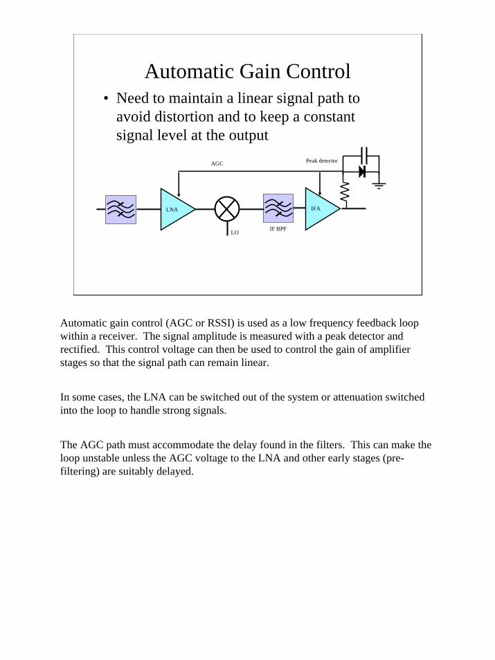
Automatic Gain Control• Need to maintain a linear signal path to
avoid distortion and to keep a constant signal level at the output
LO
LNA IFA
IF BPF
AGC Peak detector
Automatic gain control (AGC or RSSI) is used as a low frequency feedback loop within a receiver. The signal amplitude is measured with a peak detector and rectified. This control voltage can then be used to control the gain of amplifier stages so that the signal path can remain linear.
In some cases, the LNA can be switched out of the system or attenuation switched into the loop to handle strong signals.
The AGC path must accommodate the delay found in the filters. This can make the loop unstable unless the AGC voltage to the LNA and other early stages (pre-filtering) are suitably delayed.

17
Compare Superhet with Direct Conversion
• Superhet:– Benefits:
1. Low cost, high quality fixed frequency IF bandpass filters are available
2. 1/f noise at IF is negligible 3. Good dynamic range with AGC
– Challenges:1. Image and spurious signal control2. Off-chip filters consume power, area3. Power dissipation4. Simple image control solutions (LPF for example) may create a
strong signal overload problem

18
LO
Superheterodyne:
Direct conversion:
fRF
fIF
fbaseband
Channel selection
BPF
LPF
The superheterodyne or superhet architecture uses an intermediate (IF) frequency following the mixer. This is selected such that amplifiers and channel selection filters are available with suitable performance. Image rejection also plays a role as will be seen later.
The direct conversion mixes down to DC. The advantage is that filters can be integrated on chip using active or digital filter design approaches. But, LO leakage causes a DC offset. Also, the mixer in most cases must be a more complex image rejecting design because the signal and image fold over onto the same frequency.
19
Compare Superhet with Direct Conversion
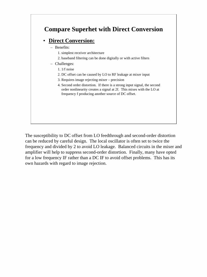
• Direct Conversion:– Benefits:
1. simplest receiver architecture2. baseband filtering can be done digitally or with active filters
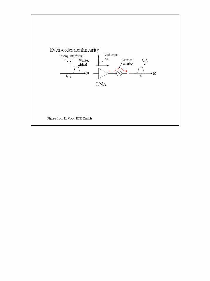
– Challenges:1. 1/f noise2. DC offset can be caused by LO to RF leakage at mixer input3. Requires image rejecting mixer – precision4. Second order distortion. If there is a strong input signal, the second
order nonlinearity creates a signal at 2f. This mixes with the LO at frequency f producing another source of DC offset.
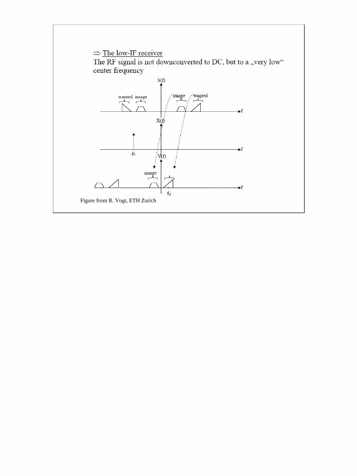
The susceptibility to DC offset from LO feedthrough and second-order distortion can be reduced by careful design. The local oscillator is often set to twice the frequency and divided by 2 to avoid LO leakage. Balanced circuits in the mixer and amplifier will help to suppress second-order distortion. Finally, many have opted for a low frequency IF rather than a DC IF to avoid offset problems. This has its own hazards with regard to image rejection.
20
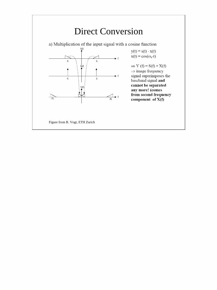
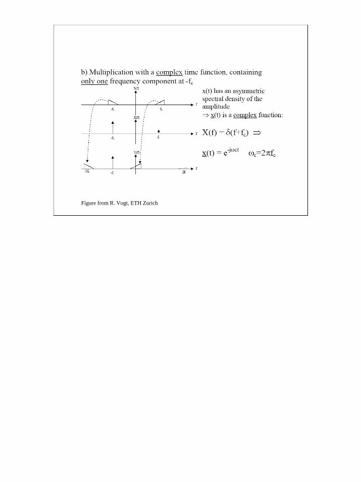
Direct Conversion
Figure from R. Vogt, ETH Zurich
21
Figure from R. Vogt, ETH Zurich
22
Figure from R. Vogt, ETH Zurich
23
Figure from R. Vogt, ETH Zurich
24
Additional reading
• See Razavi, RF Microelectronics, Chap. 5, Prentice-Hall, 1998. (on eres web)