Interfacing with other chips - The College of Engineering...
30
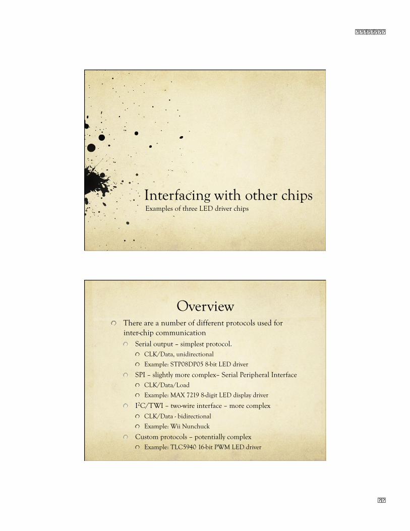
Interfacing with other chips Examples of three LED driver chips Overview There are a number of different protocols used for inter-chip communication Serial output – simplest protocol. CLK/Data, unidirectional Example: STP08DP05 8-bit LED driver SPI – slightly more complex– Serial Peripheral Interface CLK/Data/Load Example: MAX 7219 8-digit LED display driver I 2 C/TWI – two-wire interface – more complex CLK/Data - bidirectional Example: Wii Nunchuck Custom protocols – potentially complex Example: TLC5940 16-bit PWM LED driver
Transcript of Interfacing with other chips - The College of Engineering...
� � � � � � � �
� �
Interfacing with other chips Examples of three LED driver chips
Overview There are a number of different protocols used for
inter-chip communication Serial output – simplest protocol.
CLK/Data, unidirectional
Example: STP08DP05 8-bit LED driver
SPI – slightly more complex– Serial Peripheral Interface CLK/Data/Load
Example: MAX 7219 8-digit LED display driver
I2C/TWI – two-wire interface – more complex CLK/Data - bidirectional
Example: Wii Nunchuck
Custom protocols – potentially complex Example: TLC5940 16-bit PWM LED driver
� � � � � � � �
� �
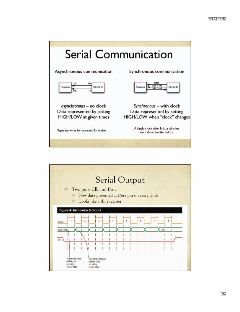
Serial Output Two pins: Clk and Data
New data presented at Data pin on every clock Looks like a shift register
� � � � � � � �
� �
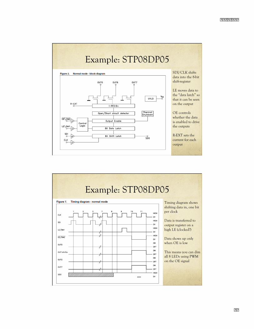
Example: STP08DP05 SDI/CLK shifts data into the 8-bit shift-register
LE moves data to the “data latch” so that it can be seen on the output
OE controls whether the data is enabled to drive the outputs
R-EXT sets the current for each output
Example: STP08DP05 Timing diagram shows shifting data in, one bit per clock
Data is transferred to output register on a high LE (clocked?)
Data shows up only when OE is low
This means you can dim all 8 LEDs using PWM on the OE signal
� � � � � � � �
�
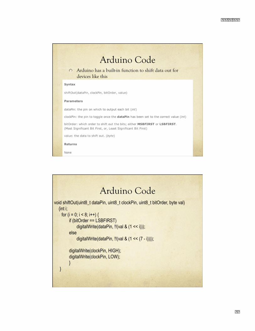
Arduino Code Arduino has a built-in function to shift data out for
devices like this
Arduino Code void shiftOut(uint8_t dataPin, uint8_t clockPin, uint8_t bitOrder, byte val) {int i;
for (i = 0; i < 8; i++) { if (bitOrder == LSBFIRST) digitalWrite(dataPin, !!(val & (1 << i))); else digitalWrite(dataPin, !!(val & (1 << (7 - i))));
digitalWrite(clockPin, HIGH); digitalWrite(clockPin, LOW); }
}
10/6/09
5
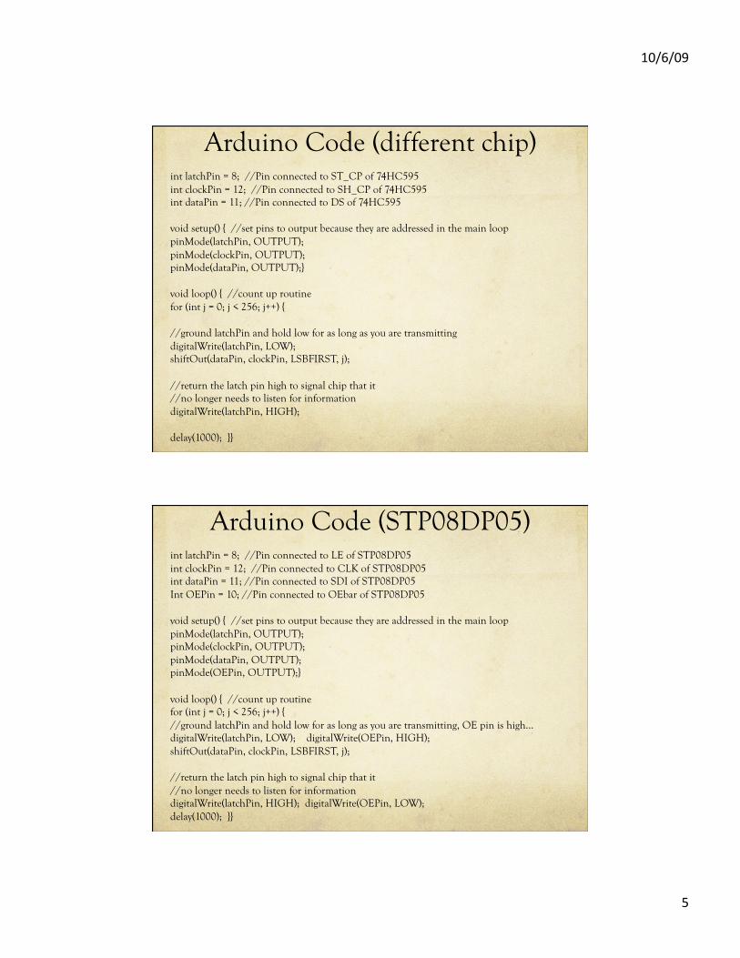
Arduino Code (different chip) int latchPin = 8; //Pin connected to ST_CP of 74HC595 int clockPin = 12; //Pin connected to SH_CP of 74HC595 int dataPin = 11; //Pin connected to DS of 74HC595
void setup() { //set pins to output because they are addressed in the main loop pinMode(latchPin, OUTPUT); pinMode(clockPin, OUTPUT); pinMode(dataPin, OUTPUT);}
void loop() { //count up routine for (int j = 0; j < 256; j++) {
//ground latchPin and hold low for as long as you are transmitting digitalWrite(latchPin, LOW); shiftOut(dataPin, clockPin, LSBFIRST, j);
//return the latch pin high to signal chip that it //no longer needs to listen for information digitalWrite(latchPin, HIGH);
delay(1000); }}
Arduino Code (STP08DP05) int latchPin = 8; //Pin connected to LE of STP08DP05 int clockPin = 12; //Pin connected to CLK of STP08DP05 int dataPin = 11; //Pin connected to SDI of STP08DP05 Int OEPin = 10; //Pin connected to OEbar of STP08DP05
void setup() { //set pins to output because they are addressed in the main loop pinMode(latchPin, OUTPUT); pinMode(clockPin, OUTPUT); pinMode(dataPin, OUTPUT); pinMode(OEPin, OUTPUT);}
void loop() { //count up routine for (int j = 0; j < 256; j++) { //ground latchPin and hold low for as long as you are transmitting, OE pin is high… digitalWrite(latchPin, LOW); digitalWrite(OEPin, HIGH); shiftOut(dataPin, clockPin, LSBFIRST, j);
//return the latch pin high to signal chip that it //no longer needs to listen for information digitalWrite(latchPin, HIGH); digitalWrite(OEPin, LOW); delay(1000); }}
� � � � � � � �
� �
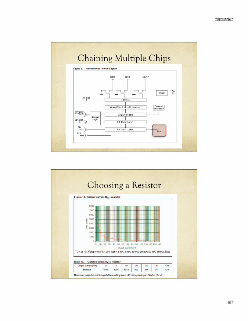
Chaining Multiple Chips
Choosing a Resistor
� � � � � � � �
� �
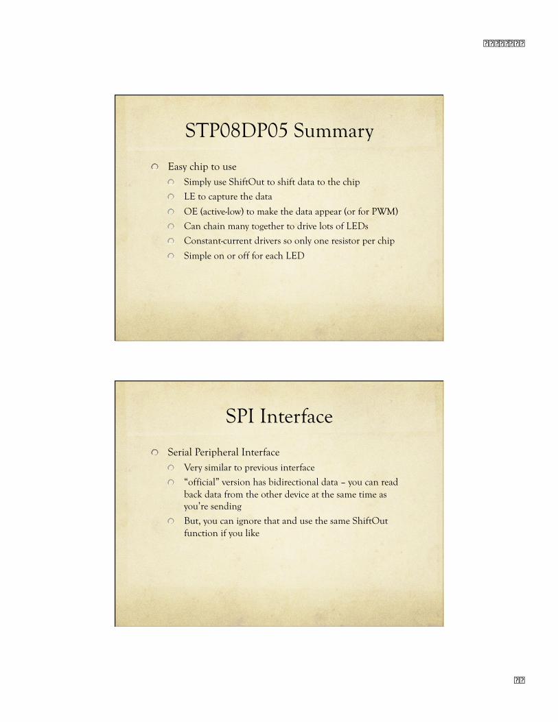
STP08DP05 Summary
Easy chip to use Simply use ShiftOut to shift data to the chip
LE to capture the data
OE (active-low) to make the data appear (or for PWM)
Can chain many together to drive lots of LEDs
Constant-current drivers so only one resistor per chip
Simple on or off for each LED
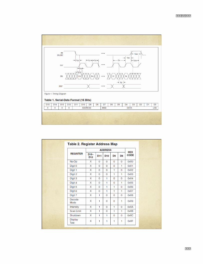
SPI Interface
Serial Peripheral Interface Very similar to previous interface
“official” version has bidirectional data – you can read back data from the other device at the same time as you’re sending
But, you can ignore that and use the same ShiftOut function if you like
� � � � � � � �
�
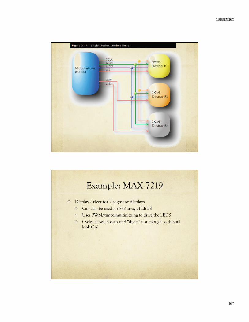
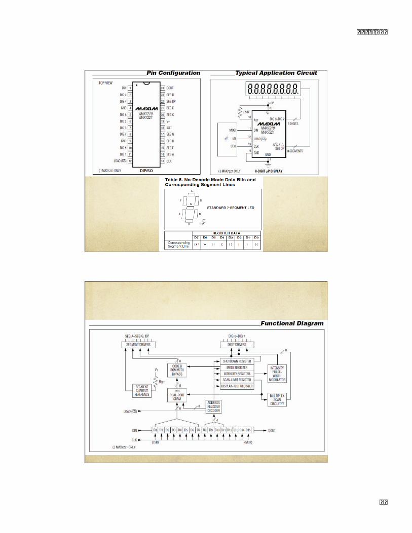
Example: MAX 7219
Display driver for 7-segment displays Can also be used for 8x8 array of LEDS
Uses PWM/timed-multiplexing to drive the LEDS
Cycles between each of 8 “digits” fast enough so they all look ON
� � � � � � � �
� �
� � � � � � � �
� � �
� � � � � � � �
� � �
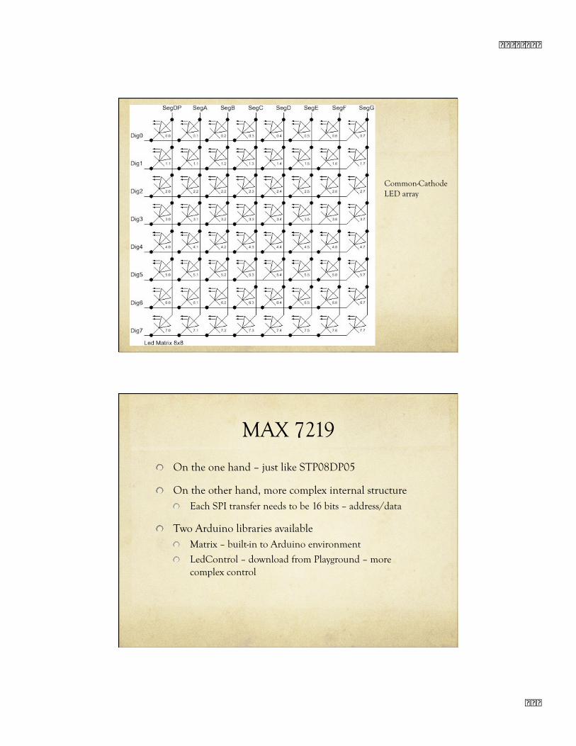
Common-Cathode LED array
MAX 7219
On the one hand – just like STP08DP05
On the other hand, more complex internal structure Each SPI transfer needs to be 16 bits – address/data
Two Arduino libraries available Matrix – built-in to Arduino environment
LedControl – download from Playground – more complex control
� � � � � � � �
� � �
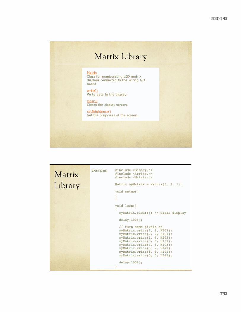
Matrix Library
Matrix Library
� � � � � � � �
� � �
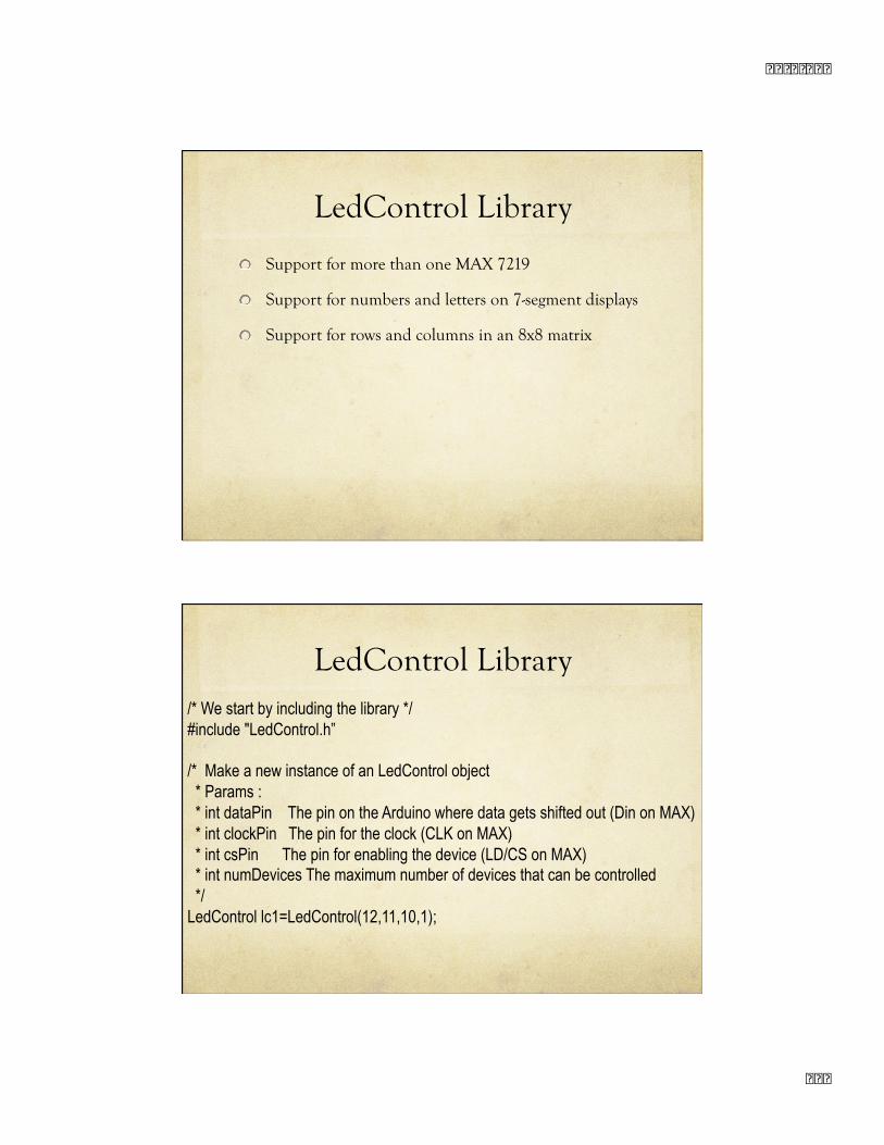
LedControl Library
Support for more than one MAX 7219
Support for numbers and letters on 7-segment displays
Support for rows and columns in an 8x8 matrix
LedControl Library /* We start by including the library */ #include "LedControl.h”
/* Make a new instance of an LedControl object * Params : * int dataPin The pin on the Arduino where data gets shifted out (Din on MAX) * int clockPin The pin for the clock (CLK on MAX) * int csPin The pin for enabling the device (LD/CS on MAX) * int numDevices The maximum number of devices that can be controlled */ LedControl lc1=LedControl(12,11,10,1);
10/6/09
14
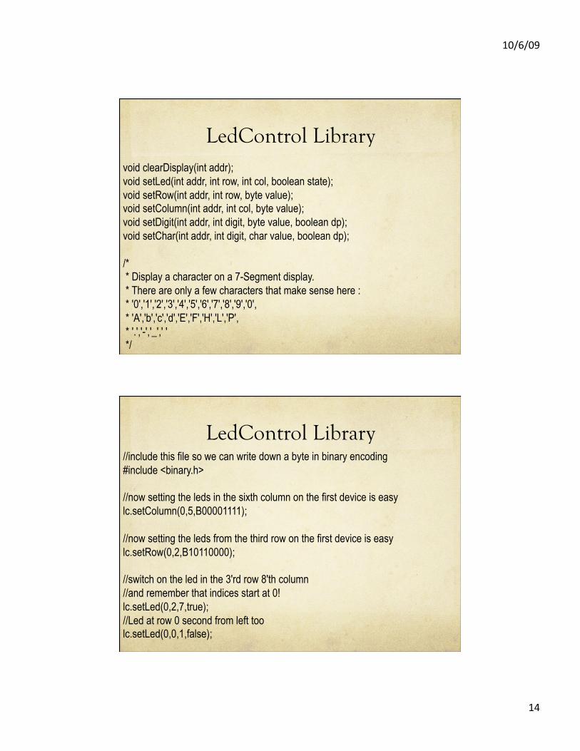
LedControl Library void clearDisplay(int addr); void setLed(int addr, int row, int col, boolean state); void setRow(int addr, int row, byte value); void setColumn(int addr, int col, byte value); void setDigit(int addr, int digit, byte value, boolean dp); void setChar(int addr, int digit, char value, boolean dp);
/* * Display a character on a 7-Segment display. * There are only a few characters that make sense here : * '0','1','2','3','4','5','6','7','8','9','0', * 'A','b','c','d','E','F','H','L','P', * '.','-','_',' ' */
LedControl Library //include this file so we can write down a byte in binary encoding #include <binary.h>
//now setting the leds in the sixth column on the first device is easy lc.setColumn(0,5,B00001111);
//now setting the leds from the third row on the first device is easy lc.setRow(0,2,B10110000);
//switch on the led in the 3'rd row 8'th column //and remember that indices start at 0! lc.setLed(0,2,7,true); //Led at row 0 second from left too lc.setLed(0,0,1,false);
� � � � � � � �
� �
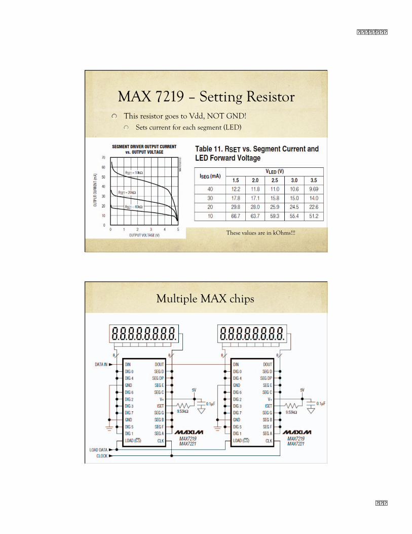
MAX 7219 – Setting Resistor This resistor goes to Vdd, NOT GND!
Sets current for each segment (LED)
These values are in kOhms!!!
Multiple MAX chips
� � � � � � � �
� � �
Multiple MAX Chips
There is an important difference between the way the setRow() and the setColumn() methods update the Leds: setRow() only needs to send a single int-value to the
MAX72XX in order to update all 8 Leds in a row. setColumn() uses the setLed()-method internally to
update the Leds. The library has to send 8 ints to the driver, so there is a performance penalty when using setColumn().
You won't notice that visually when using only 1 or 2 cascaded Led-boards, but if you have a long queue of devices (6..8) which all have to be updated at the same time, that could lead to some delay that is actually visible.
MAX 7219 Summary
Drives more LEDs than the STP08DP05 Designed for common-cathode LED arrays
Set the anodes to true and false
Pull down the cathodes in sequence
Uses time-multiplexing to drive them all
Also supports 7-segment displays
Slightly more complex interface
� � � � � � � �
� � �
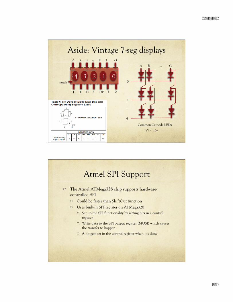
Aside: Vintage 7-seg displays A B
4 3 2 1 0
3 nc F 1 G
4 E C 2 DP D 0
notch
A B G …
0
1
…
4
Common-Cathode LEDs
Vf = 1.6v
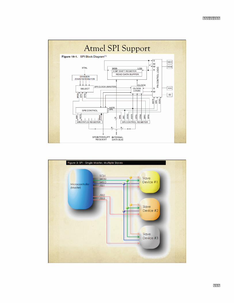
Atmel SPI Support
The Atmel ATMega328 chip supports hardware-controlled SPI Could be faster than ShiftOut function
Uses built-in SPI register on ATMega328 Set up the SPI functionality by setting bits in a control
register
Write data to the SPI output register (MOSI) which causes the transfer to happen
A bit gets set in the control register when it’s done
� � � � � � � �
� �
Atmel SPI Support
� � � � � � � �
� � �
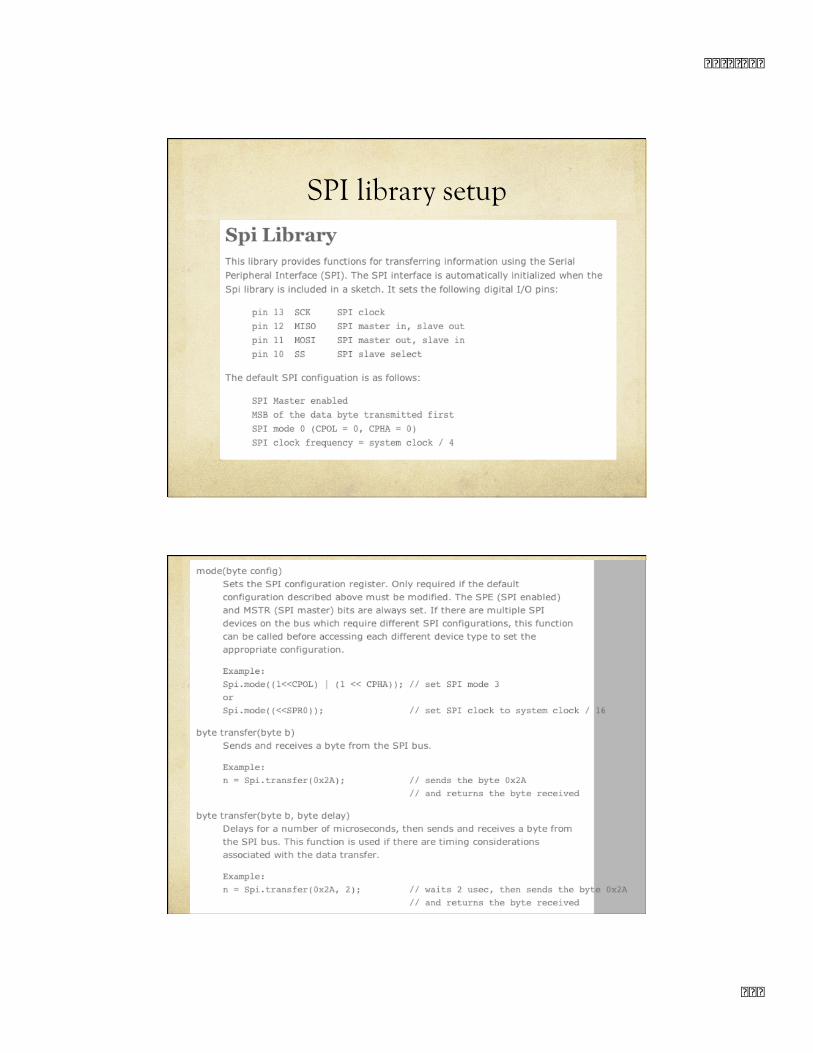
SPI library setup
� � � � � � � �
� � �
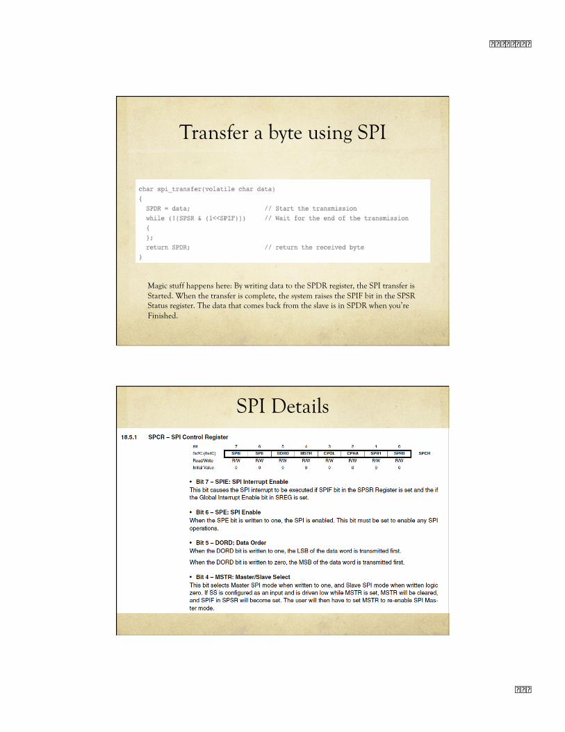
Transfer a byte using SPI
Magic stuff happens here: By writing data to the SPDR register, the SPI transfer is Started. When the transfer is complete, the system raises the SPIF bit in the SPSR Status register. The data that comes back from the slave is in SPDR when you’re Finished.
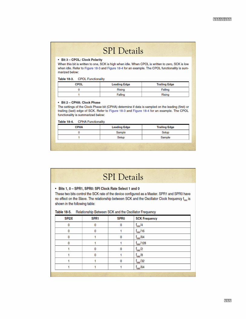
SPI Details
� � � � � � � �
� � �
SPI Details
SPI Details
� � � � � � � �
� � �
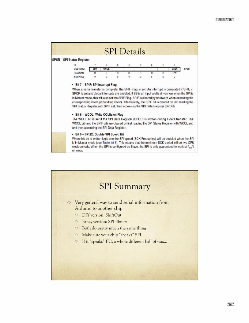
SPI Details
SPI Summary
Very general way to send serial information from Arduino to another chip DIY version: ShiftOut
Fancy version: SPI library
Both do pretty much the same thing
Make sure your chip “speaks” SPI
If it “speaks” I2C, a whole different ball of wax…
� � � � � � � �
� � �
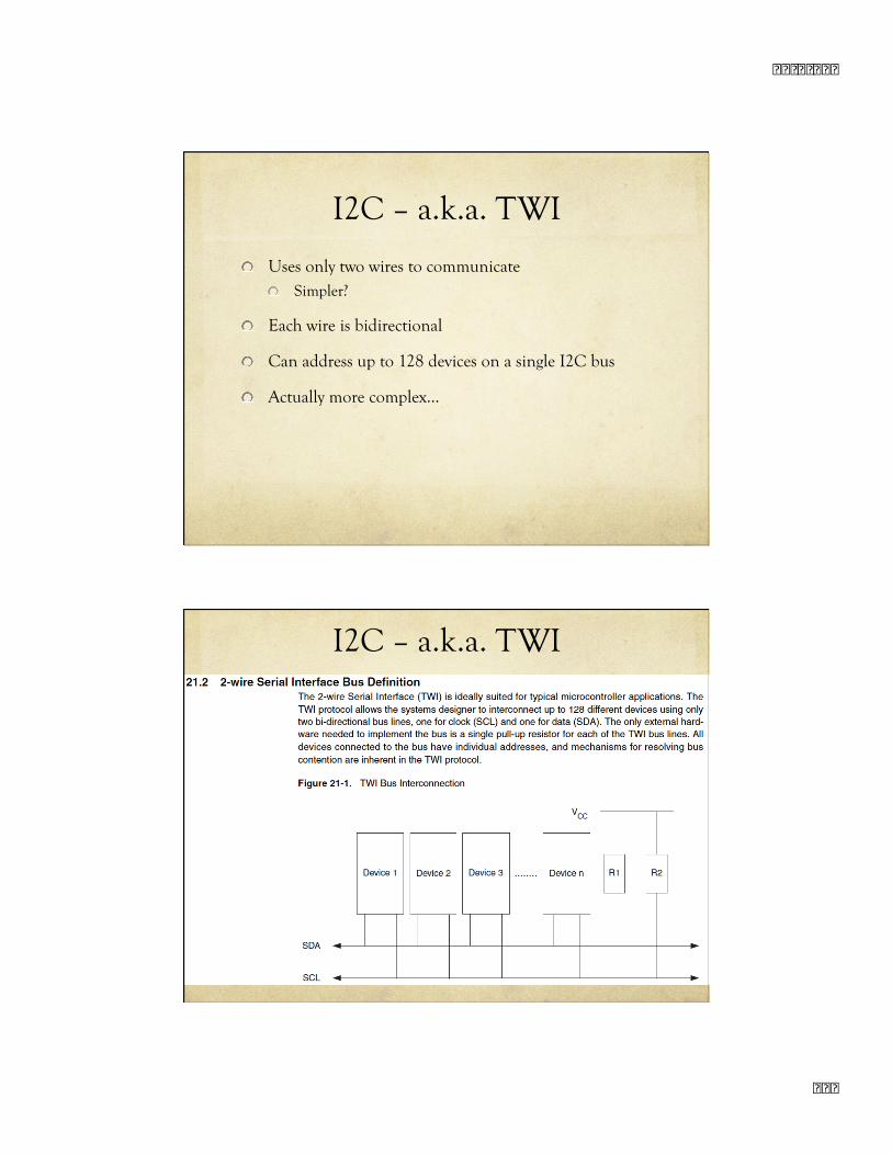
I2C – a.k.a. TWI
Uses only two wires to communicate Simpler?
Each wire is bidirectional
Can address up to 128 devices on a single I2C bus
Actually more complex…
I2C – a.k.a. TWI
� � � � � � � �
� �
I2C – a.k.a. TWI I2C – a.k.a. TWI
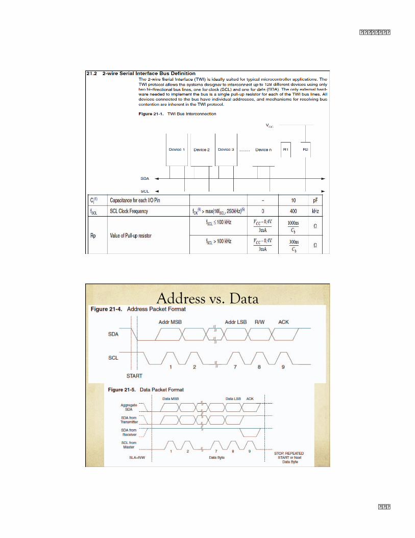
Address vs. Data
� � � � � � � �
� �
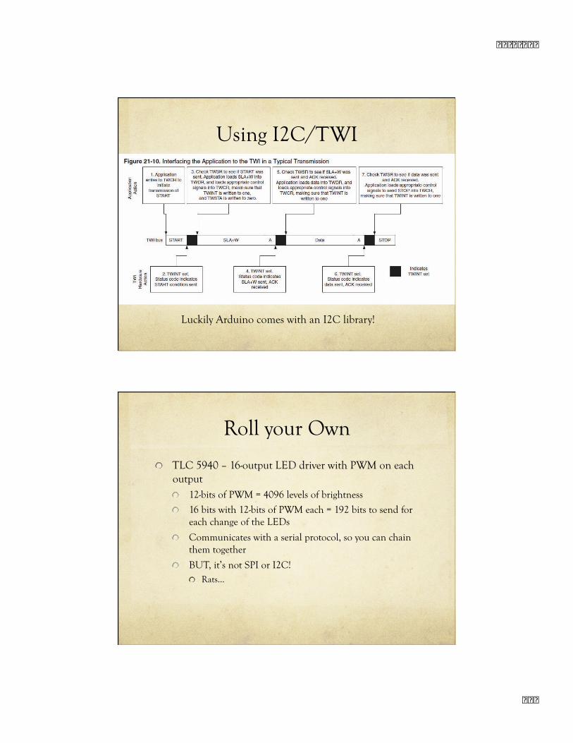
Using I2C/TWI
Luckily Arduino comes with an I2C library!
Roll your Own
TLC 5940 – 16-output LED driver with PWM on each output 12-bits of PWM = 4096 levels of brightness
16 bits with 12-bits of PWM each = 192 bits to send for each change of the LEDs
Communicates with a serial protocol, so you can chain them together
BUT, it’s not SPI or I2C! Rats…
� � � � � � � �
� � �
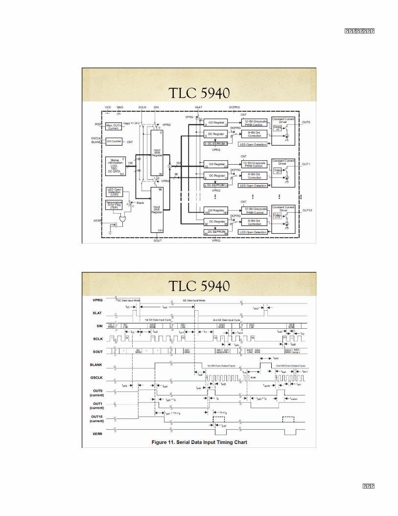
TLC 5940
TLC 5940
� � � � � � � �
� � �
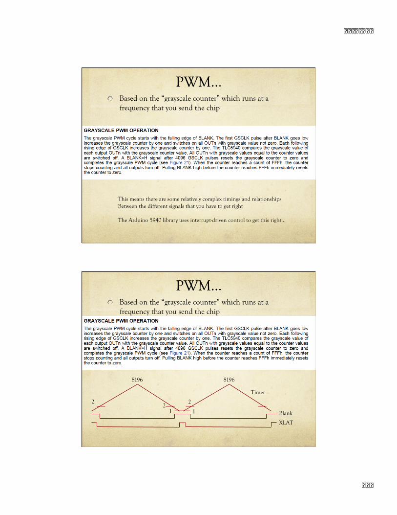
PWM… Based on the “grayscale counter” which runs at a
frequency that you send the chip
This means there are some relatively complex timings and relationships Between the different signals that you have to get right
The Arduino 5940 library uses interrupt-driven control to get this right…
PWM… Based on the “grayscale counter” which runs at a
frequency that you send the chip
2 2
8196 8196
2
1 1
XLAT
Blank
Timer
� � � � � � � �
� �
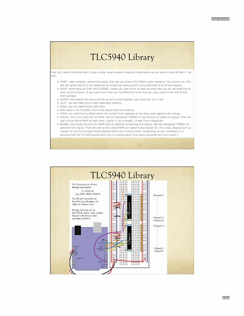
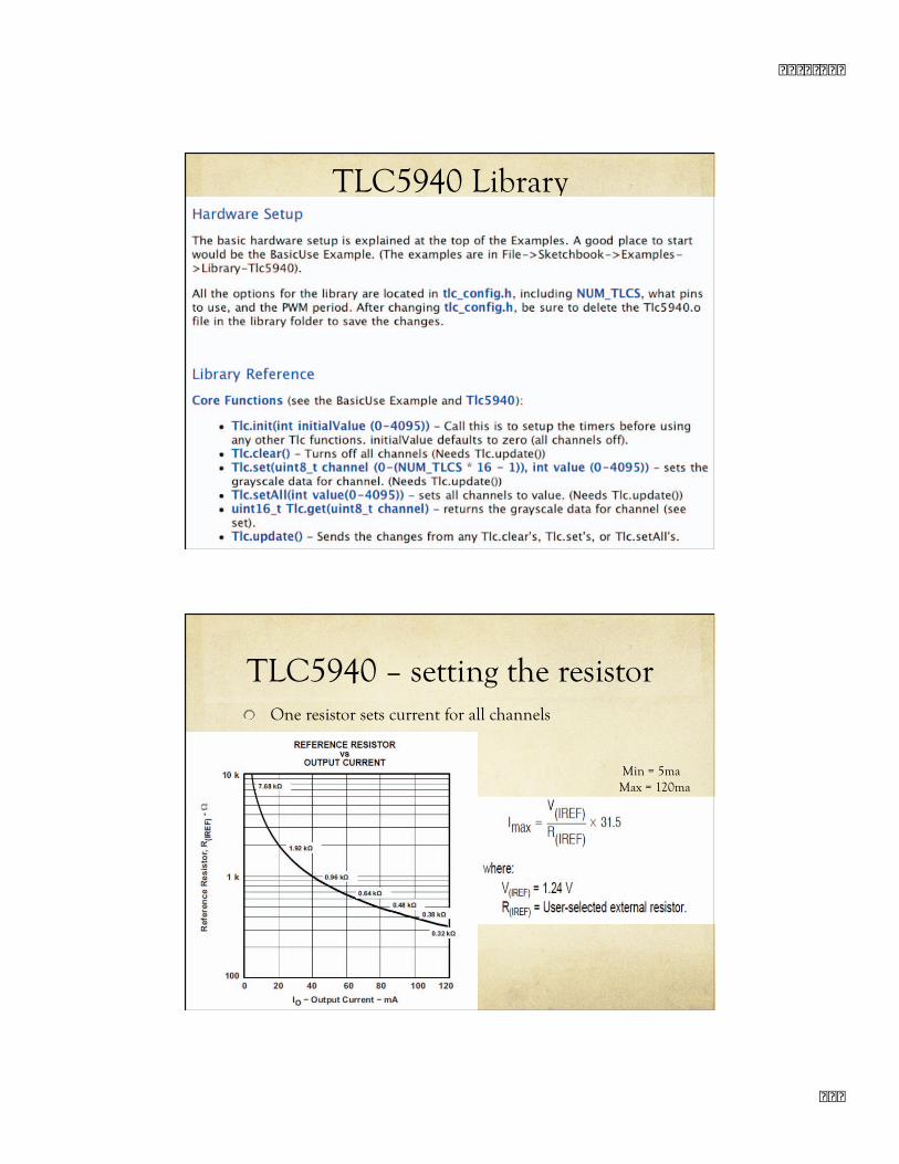
TLC5940 Library
TLC5940 Library
� � � � � � � �
� � �
TLC5940 Library TLC5940 Library
TLC5940 – setting the resistor One resistor sets current for all channels
Min = 5ma Max = 120ma
� � � � � � � �
� � �
TLC5940 Summary
Easy to use – if you use the tlc5940 library!
Can also use for servo control Use the PWM channels to drive servos
Remember about power issues!
Summary
There are lots of ways to interface with other chips shiftOut() – simple serial
Output only
SPI – standard serial protocol – three wires CLK, DATA, En Can be bi-directional
I2C / TWI – two wire protocol – requires a little more complex addressing and protocol, and pullup resistors Can also be bidirectional
Non-standard serial – read the data sheet carefully!