INTERFACING WITH OTHER CHIPS - The College of ...cs5789/Slides/LEDsx2.pdfINTERFACING WITH OTHER...
63
1/20/14 1 INTERFACING WITH OTHER CHIPS Examples of three LED driver chips Why Add Other Chips? Lots of cool chips out there that add functionality beyond a basic Arduino
Transcript of INTERFACING WITH OTHER CHIPS - The College of ...cs5789/Slides/LEDsx2.pdfINTERFACING WITH OTHER...
1/20/14
1
INTERFACING WITH OTHER CHIPS Examples of three LED driver chips
Why Add Other Chips?
¨ Lots of cool chips out there that add functionality beyond a basic Arduino

1/20/14
2
Why Add Other Chips?
¨ Lots of cool chips out there that add functionality beyond a basic Arduino ¤ Accelerometers / gyros
Why Add Other Chips?
¨ Lots of cool chips out there that add functionality beyond a basic Arduino ¤ Accelerometers / gyros ¤ GPS

1/20/14
3
Why Add Other Chips?
¨ Lots of cool chips out there that add functionality beyond a basic Arduino ¤ Accelerometers / gyros ¤ GPS ¤ audio – amps, external ADC/DAC, etc.
Why Add Other Chips?
¨ Lots of cool chips out there that add functionality beyond a basic Arduino ¤ Accelerometers / gyros ¤ GPS ¤ audio – amps, external ADC/DAC, etc. ¤ displays – FVD, TFT, etc.

1/20/14
4
Why Add Other Chips?
¨ Lots of cool chips out there that add functionality beyond a basic Arduino ¤ Accelerometers / gyros ¤ GPS ¤ audio – amps, external ADC/DAC, etc. ¤ displays – FVD, TFT, etc. ¤ Environmental sensors – temp, humidity, barometer, etc.
Why Add Other Chips?
¨ Lots of cool chips out there that add functionality beyond a basic Arduino ¤ LEDs – lots of ‘em

1/20/14
5
Why Add Other Chips?
¨ Driving External LEDs ¤ From an Arduino you can drive 14 LEDs directly from
the digital outs – what if you want more? ¤ Use external LED-driver chip ¤ Send data on which LEDs to turn on and of to that chip ¤ Let it keep track of the LEDs while you do other things
Leo Villareal
National Gallery of Art

1/20/14
6
Leo Villareal
National Gallery of Art
Leo Villareal

1/20/14
7
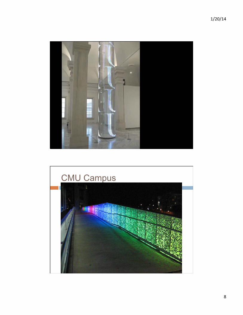
Jenny Holzer
Smithsonian
Cylinder of LED strips 28 feet tall 4 feet in diameter
University of Utah • CS/EE 3710
1/20/14
8
University of Utah • CS/EE 3710 Smithsonian
Cylinder of LED strips 28 feet tall 4 feet in diameter
CMU Campus
University of Utah • CS/EE 3710

1/20/14
9
Aristarkh Chernyshev
Jim Campbell (1956 - )

1/20/14
10
Jim Campbell (1956 - )
Jim Campbell (1956 - )

1/20/14
11
Communication Styles
¨ Parallel = multiple wires in parallel
¨ Serial = send data one at a time on one wire ¤ In practice you usually need two
wires: one for the data, and one to say when to look at the data (usually called Clock)
¨ So, serial communication takes more time, but uses fewer wires
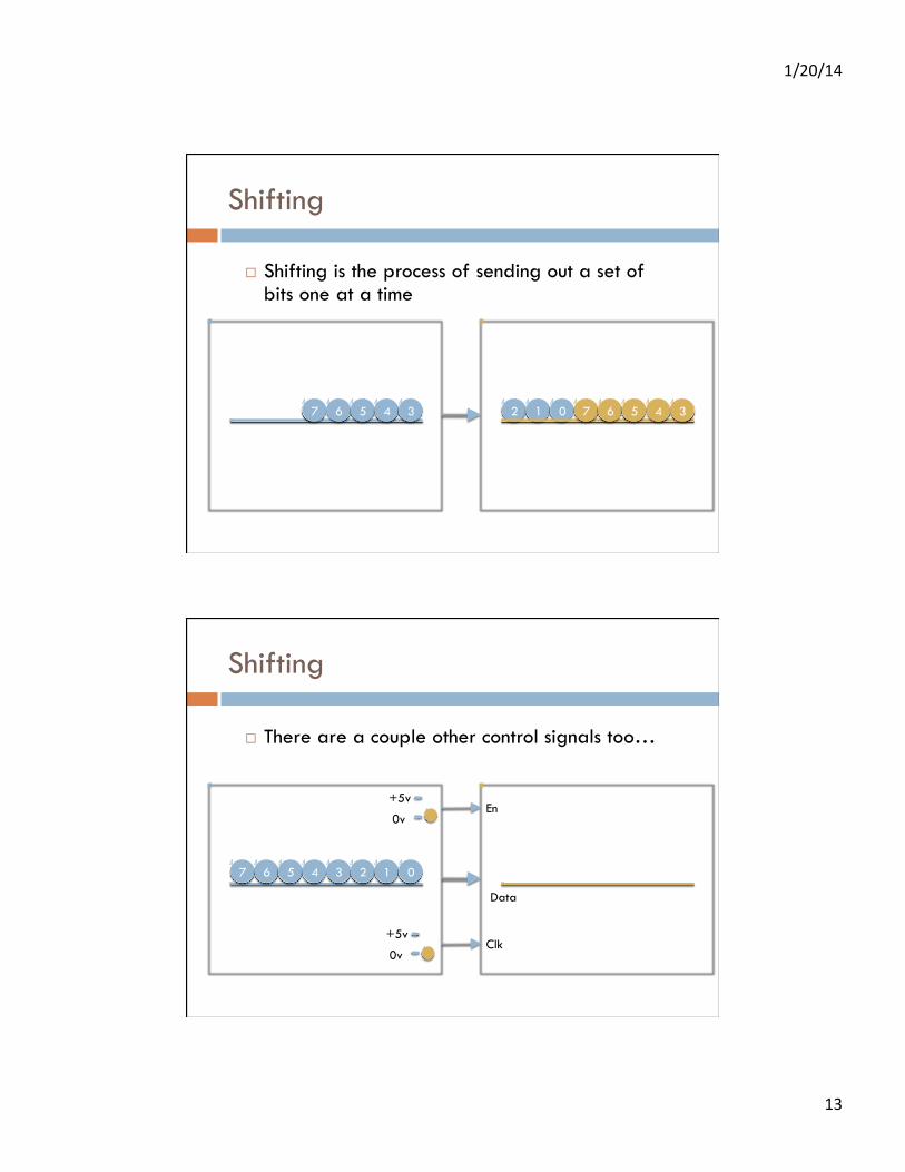
Shifting
¨ Shifting is the process of sending out a set of bits one at a time
7 6 5 4 3 2 1 0 7 6 5 4 3 2 1 0

1/20/14
12
Shifting
¨ Shifting is the process of sending out a set of bits one at a time
7 6 5 4 3 2 1 0 7 6 5 4 3 2 1
Shifting
¨ Shifting is the process of sending out a set of bits one at a time
7 6 5 4 3 2 1 0 7 6 5 4 3 2
1/20/14
13
Shifting
¨ Shifting is the process of sending out a set of bits one at a time
7 6 5 4 3 2 1 0 7 6 5 4 3
Shifting
¨ There are a couple other control signals too…
7 6 5 4 3 2 1 0
En
Clk
Data
0v
+5v
0v
+5v

1/20/14
14
Overview
¨ There are a number of different protocols used for inter-chip communication (Arduino to external chip…) ¤ Serial output – simplest protocol
n Also called SPI – Serial Peripheral Interface n CLK/Data/En, unidirectional n Example: STP08DP05 8-bit LED driver
Overview
¨ There are a number of different protocols used for inter-chip communication (Arduino to external chip…) ¤ Serial output – SPI
n Example: STP08DP05 8-bit LED driver
¤ SPI with more complex operation n Send data with SPI, both commands and data n Example: MAX 7219 8-digit LED display driver n Also LED strips

1/20/14
15
Overview
¨ There are a number of different protocols used for inter-chip communication (Arduino to external chip…) ¤ Serial output – SPI
n Example: STP08DP05 8-bit LED driver
¤ SPI with more complex operation n Example: MAX 7219 8-digit LED display driver n LED strips
¤ I2C/TWI – two-wire interface – more complex n CLK/Data - bidirectional n Example: Wii Nunchuck
Overview
¨ There are a number of different protocols used for inter-chip communication (Arduino to external chip…) ¤ Serial output – SPI
n Example: STP08DP05 8-bit LED driver
¤ SPI with more complex operation n Example: MAX 7219 8-digit LED display driver
¤ I2C/TWI – two-wire interface – more complex n Example: Wii Nunchuck
¤ Custom protocols – potentially complex n Example: TLC5940 16-bit PWM LED driver

1/20/14
16
SPI Serial Output
¨ Two pins: Clk and Data ¤ New data presented at Data pin on every clock ¤ Looks like a shift register
Example: Shift Register
¨ Simply connect LEDs to the outputs of the shift register ¨ The only problem is that the LED pattern changes while
you’re shifting it in…
7 6 5 4 3 2 1 0 7 6 5 4 3
GND
Arduino External shift register

1/20/14
17
Shifter with Output Latch
¨ One solution is to save the current outputs while you’re shifting in the new ones ¤ This is an “output latch” ¤ Shift in new stuff “underneath” the bits that are being
displayed ¤ Then, all at once, swap the new bits for the old bits
Shifting w/Latch
¨ latch when LE goes high ¨ Outputs enabled when OE is low
7 6 5 4 3 2 1 0
OE
LE (Latch Enable)
Data
0v
+5v
0v
+5v
7 6 5 4 3 2 1 0
Arduino External Chip

1/20/14
18
Shifting w/Latch
¨ latch when LE goes high ¨ Outputs enabled when OE is low
7 6 5 4 3 2 1 0
OE
LE (Latch Enable)
Data
0v
+5v
0v
+5v
7 6 5 4 3 2 1 0
7 6 5 4 3 2 1 0
Arduino External Chip
Example: 74HC595 ¨ This is a shift register
with an output latch ¤ You can save the previous values
while shifting in new ones ¤ BUT – need separate current-
limiting resistor for each LED!

1/20/14
19
Example: STP08DP05
¨ Just like the 74HC595 – a shift register with a separate output latch
¨ ALSO – constant-current outputs for the LEDs ¤ That means the outputs limit the current for you ¤ You set the output current with a single resistor for all 8
outputs ¤ Only one resistor for 8 LEDs!
Example: STP08DP05
SDI/CLK shifts data into the 8-bit shift-register LE moves data to the “data latch” so that it can be seen on the output OE controls whether the data is enabled to drive the outputs R-EXT sets the current limit for all outputs

1/20/14
20
Constant Current Source
¨ Note that the constant current source only pulls to ground ¤ So – LEDs connect to vdd…
+5v
Constant Current Source
¨ Note that the constant current source only pulls to ground ¤ So – LEDs connect to vdd…
+5v
Resistor to GND to set current limit

1/20/14
21
Example: STP08DP05
Timing diagram shows shifting data in, one bit per clock Data is transferred to output register on a high LE Data shows up only when OE is low This means you can dim all 8 LEDs using PWM on the OE signal
Arduino Code
¨ Arduino has a built-in function to shift data out for devices like this

1/20/14
22
Internal Arduino Code for shiftOut()
void shiftOut(uint8_t dataPin, uint8_t clockPin, uint8_t bitOrder, byte val) {int i;
for (i = 0; i < 8; i++) { if (bitOrder == LSBFIRST) digitalWrite(dataPin, !!(val & (1 << i))); else digitalWrite(dataPin, !!(val & (1 << (7 - i))));
digitalWrite(clockPin, HIGH); digitalWrite(clockPin, LOW); }
}
User Arduino Code (STP08DP05) const int latchPin = 8; //Pin connected to LE of STP08DP05 const int clockPin = 12; //Pin connected to CLK of STP08DP05 const int dataPin = 11; //Pin connected to SDI of STP08DP05 const int OEPin = 10; //Pin connected to OEbar of STP08DP05 void setup() { //set pins to output because they are addressed in the main loop pinMode(latchPin, OUTPUT); pinMode(clockPin, OUTPUT); pinMode(dataPin, OUTPUT); pinMode(OEPin, OUTPUT);} void loop() { //count up routine
for (int j = 0; j < 256; j++) { // count i from 0 to 255 (00000000 to 11111111)
//ground latchPin and hold low for as long as you are transmitting, OE pin is high… digitalWrite(latchPin, LOW); digitalWrite(OEPin, HIGH);
shiftOut(dataPin, clockPin, LSBFIRST, j); // shift out the value of j
//return the latch pin high to transfer data to output latch, OE low to light the LEDs digitalWrite(latchPin, HIGH); digitalWrite(OEPin, LOW);
delay(1000); }}

1/20/14
23
Chaining Multiple Chips
Choosing a Resistor
¨ I chose a 2k ohm resistor for around 10ma

1/20/14
24
STP08DP05 Summary
¨ Easy chip to use ¤ Use ShiftOut(…) to shift data to the chip ¤ Can chain many together to drive lots of LEDs
¨ Just four wires from Arduino to external chip drives 8 LEDs (per chip – you can also chain) ¤ Clk and Data used to shiftOut() the data ¤ LE goes high to capture the data ¤ OE goes low to make the data appear (or for PWM)
¨ Constant-current drivers so only one resistor per chip ¤ Simple on or off for each LED
SPI Interface
¨ Serial Peripheral Interface ¤ Generalized version of previous example ¤ “official” version has bidirectional data – you can read
back data from the other device at the same time as you’re sending
¤ But, you can ignore that and use the same ShiftOut function if you like

1/20/14
25
Example: MAX 7219
¨ Display driver for 8-digits of 7-segment numbers ¤ Can also be used for 8x8 array of LEDS
n (i.e. 64 individual LEDs)
¨ Drives common-cathode LED digits or LED matrix ¤ Cycles between each of 8 digits (or matrix rows)
fast enough so they all look ON ¨ SPI interface
¤ Slightly complicated command/data interface ¤ Send address of internal register followed by data ¤ Each SPI communication is 16 bits ¤ Luckily, there’s an Arduino library for the chip

1/20/14
26

1/20/14
27

1/20/14
28
Common-Cathode LED array
MAX 7219
¨ On the one hand – just like STP08DP05 ¨ On the other hand, more complex internal structure
¤ Each SPI transfer needs to be 16 bits – address/data
¨ (at least) Two Arduino libraries available ¤ Matrix – built-in to Arduino environment ¤ LedControl – download from Playground – more
complex control
1/20/14
29
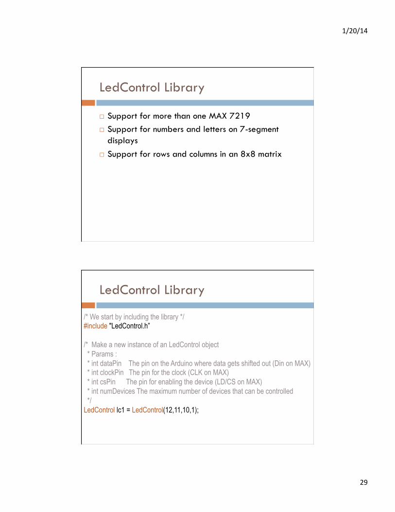
LedControl Library
¨ Support for more than one MAX 7219 ¨ Support for numbers and letters on 7-segment
displays ¨ Support for rows and columns in an 8x8 matrix
LedControl Library
/* We start by including the library */ #include "LedControl.h” /* Make a new instance of an LedControl object * Params : * int dataPin The pin on the Arduino where data gets shifted out (Din on MAX) * int clockPin The pin for the clock (CLK on MAX) * int csPin The pin for enabling the device (LD/CS on MAX) * int numDevices The maximum number of devices that can be controlled */ LedControl lc1 = LedControl(12,11,10,1);

1/20/14
30
LedControl Library
void clearDisplay(int addr); void setLed(int addr, int row, int col, boolean state); void setRow(int addr, int row, byte value); void setColumn(int addr, int col, byte value); void setDigit(int addr, int digit, byte value, boolean dp); void setChar(int addr, int digit, char value, boolean dp); /* * Display a character on a 7-Segment display. * There are only a few characters that make sense here : * '0','1','2','3','4','5','6','7','8','9','0', * 'A','b','c','d','E','F','H','L','P', * '.','-','_',' ' */
LedControl Library //include this file so we can write down a byte in binary encoding #include <binary.h> //now setting the leds in the sixth column on the first device is easy lc.setColumn(0,5,B00001111); //now setting the leds from the third row on the first device is easy lc.setRow(0,2,B10110000); //switch on the led in the 3'rd row 8'th column //and remember that indices start at 0! lc.setLed(0,2,7,true); //Led at row 0 second from left too lc.setLed(0,0,1,false);

1/20/14
31
LedControl Library
void writeArduinoOnMatrix() { /* here is the data for the characters */ byte a[5]={B01111110,B10001000,B10001000,B10001000,B01111110}; byte r[5]={B00111110,B00010000,B00100000,B00100000,B00010000}; byte d[5]={B00011100,B00100010,B00100010,B00010010,B11111110}; byte u[5]={B00111100,B00000010,B00000010,B00000100,B00111110}; byte i[5]={B00000000,B00100010,B10111110,B00000010,B00000000}; byte n[5]={B00111110,B00010000,B00100000,B00100000,B00011110}; byte o[5]={B00011100,B00100010,B00100010,B00100010,B00011100}; /* now display them one by one with a small delay */ lc.setRow(0,0,a[0]); lc.setRow(0,1,a[1]); lc.setRow(0,2,a[2]); lc.setRow(0,3,a[3]); lc.setRow(0,4,a[4]); delay(delaytime);
lc.setRow(0,0,r[0]); lc.setRow(0,1,r[1]); lc.setRow(0,2,r[2]); lc.setRow(0,3,r[3]); lc.setRow(0,4,r[4]); delay(delaytime);
MAX 7219 – Current Setting Resistor
¨ This resistor goes to Vdd, NOT GND! ¤ Sets current for each segment (LED)
These values are in kOhms!!!

1/20/14
32
Multiple MAX chips
Multiple MAX chips

1/20/14
33
Multiple MAX Chips
¨ There is an important difference between the way the setRow() and the setColumn() methods update the Leds: ¤ setRow() only needs to send a single int-value to the
MAX72XX in order to update all 8 Leds in a row. ¤ setColumn() uses the setLed()-method internally to
update the Leds. The library has to send 8 ints to the driver, so there is a performance penalty when using setColumn().
¤ You won't notice that visually when using only 1 or 2 cascaded Led-boards, but if you have a long queue of devices (6..8) which all have to be updated at the same time, that could lead to some delay that is actually visible.
MAX 7219 Summary
¨ Drives lots more LEDs than the STP08DP05 ¤ 64 LEDs total ¤ Designed for common-cathode LED arrays
n Set the anodes to true and false n Pull down the cathodes in sequence
¤ Uses time-multiplexing to drive them all
¨ Also supports 7-segment displays ¤ Slightly more complex interface

1/20/14
34
MAX7219 demo
MAX7219 demo

1/20/14
35
MAX7219 demo
MAX7219 demo

1/20/14
36
Activity
¨ Write some Arduino code to make a pattern on an 8x8 LED array ¤ You can wire one up if you like
n We have LED matrics and Max7219 chips n Around 20 wires to add…
¤ Or you can use one of mine n Pre-wired n Get practice writing code that drives the display
Atmel SPI Support
¨ The Atmel ATMega328 chip supports hardware-controlled SPI ¤ Could be faster than shiftOut() function ¤ Uses built-in SPI register on ATMega328
n Set up the SPI functionality by setting bits in a control register n Write data to the SPI output register (MOSI) which causes the
transfer to happen n A bit gets set in the control register when it’s done n Fixed pin assignments (shiftOut() can use any pins)

1/20/14
37
Atmel SPI Support

1/20/14
38
SPI library setup
SPI Library Usage
#include <SPI.h> // include library int SS = 10; // define Slave Select pin In setup: pinMode(SS, OUTPUT); // SS must be output
SPI.begin(); // init the library SPI.setBitOrder(MSBFIRST); // modify bit order
To use: SPI.transfer(byte); // transfer one byte
n = SPI.transfer(byte) // returns bytes from slave

1/20/14
39
Transfer a byte using SPI
char spi_transfer(volatile char data) { SPDR = data ; // start transmission while (!(SPSR & (1<<SPIF))) // wait for transmission
{ } ; // to finish (SPIF bit flag) return SPDR; // return received byte
} Magic stuff happens here: By writing data to the SPDR register, the SPI transfer is started. When the transfer is complete, the system raises the SPIF bit in the SPSR status register. The data that comes back from the slave is in SPDR when you’re finished.
SPI Details

1/20/14
40
SPI Details
SPI Details

1/20/14
41
SPI Details
SPI Summary
¨ Very general way to send serial information from Arduino to another chip ¤ DIY version: ShiftOut
n use any pins
¤ Fancy version: SPI library n uses fixed pins
¤ Both do pretty much the same thing

1/20/14
42
Example LED “tape”
¨ RGB LEDs on a long tape ¤ individually addressable and writable using SPI ¤ 32 RGB LEDs per Meter ($35/meter at Adafruit)
Example LED “tape”

1/20/14
43
Example LED “tape”
Example LED “tape”

1/20/14
44
SPI Summary
¨ Very general way to send serial information from Arduino to another chip ¤ DIY version: ShiftOut
n use any pins
¤ Fancy version: SPI library n uses fixed pins
¤ Both do pretty much the same thing
¨ Make sure your chip “speaks” SPI ¤ If it “speaks” I2C, a whole different ball of wax…
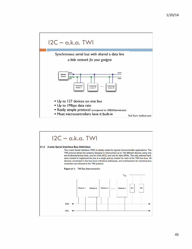
I2C – a.k.a. TWI
¨ Uses only two wires to communicate ¤ Simpler?
¨ Each wire is bidirectional ¨ Can address up to 128 devices on a single I2C bus
¤ Actually more complex…
1/20/14
45
I2C – a.k.a. TWI
Tod Kurt: todbot.com
I2C – a.k.a. TWI

1/20/14
46
I2C – a.k.a. TWI
1.8k, 4.7k. 10k are commonly used pullup resistor values The wire library for Arduino can even use the built-in resistors on the AVR
Address vs. Data

1/20/14
47
Using I2C/TWI
Luckily Arduino comes with an I2C library!
Wire Library

1/20/14
48
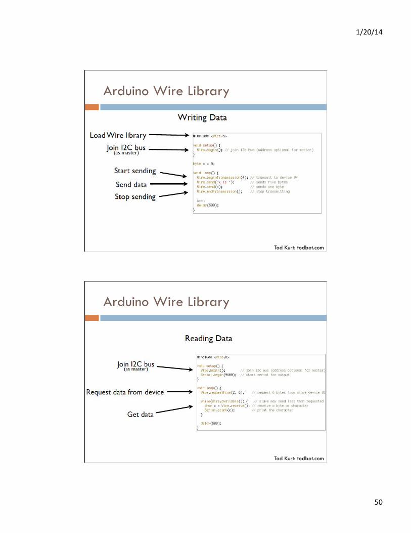
#include <Wire.h> // TWI (I2C) sketch to communicate with the LIS3LV02DQ accelerometer // Using the Wire library (created by Nicholas Zambetti) // On the Arduino board, Analog In 4 is SDA, Analog In 5 is SCL // The Wire class handles the TWI transactions, abstracting the nitty-gritty to make // prototyping easy. void setup(){ pinMode(9, OUTPUT); digitalWrite(9, HIGH); Serial.begin(9600); Wire.begin(); // join i2c bus (address optional for master) Wire.beginTransmission(0x1D); Wire.send(0x20); // CTRL_REG1 (20h) Wire.send(0x87); // Device on, 40hz, normal mode, all axis's enabled Wire.endTransmission(); }
// Switch to Wii Nunchuck Slides!
Wii Nunchuck Controller
Tod Kurt: todbot.com

1/20/14
49
Wii Nunchuck Controller
Tod Kurt: todbot.com
I2C on Arduino
328
Tod Kurt: todbot.com
1/20/14
50
Arduino Wire Library
Tod Kurt: todbot.com
Arduino Wire Library
Tod Kurt: todbot.com
1/20/14
51
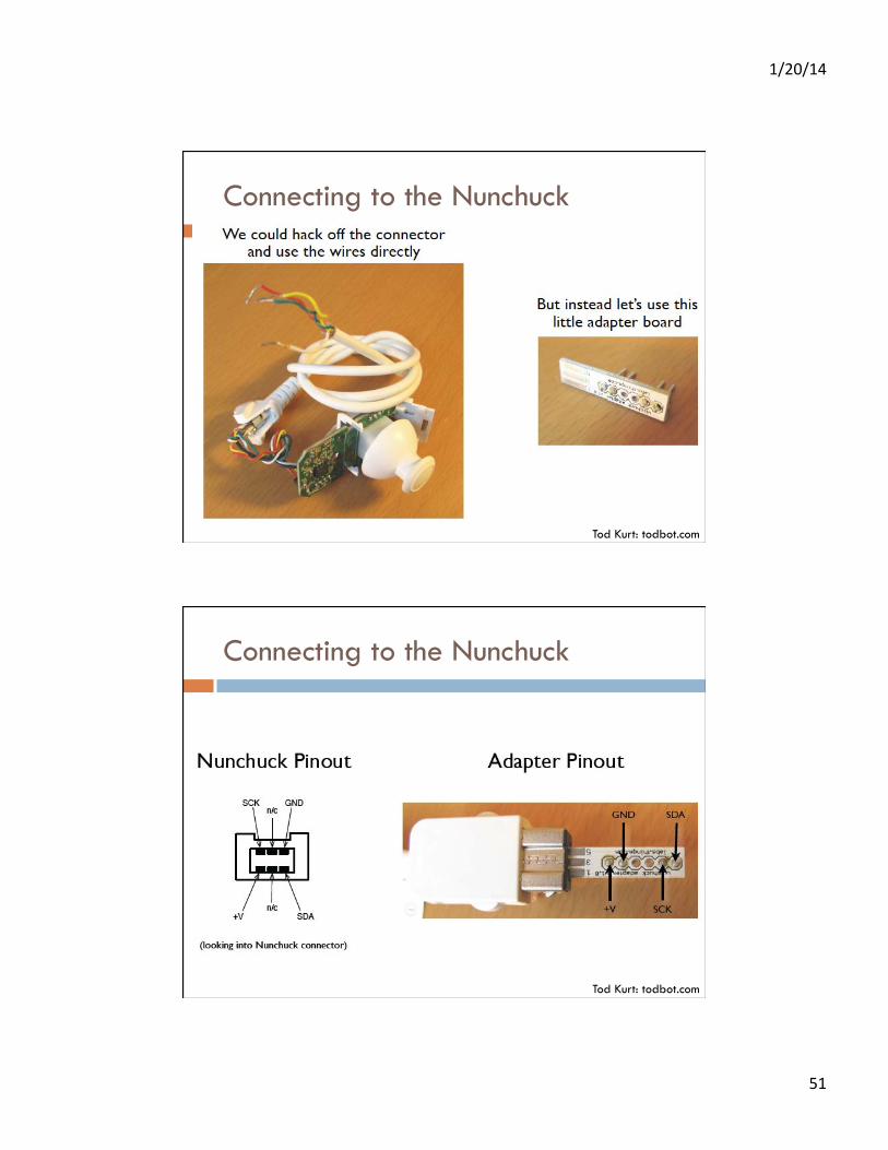
Connecting to the Nunchuck
Tod Kurt: todbot.com
Connecting to the Nunchuck
Tod Kurt: todbot.com

1/20/14
52
Connecting to the Nunchuck
Tod Kurt: todbot.com
Connecting to the Nunchuck
Tod Kurt: todbot.com

1/20/14
53
Connecting to the Nunchuck
¨ Use Tod Kurt’s library http://todbot.com/blog/2008/02/18/wiichuck-wii-nunchuck-adapter-available/
¨ or WiiChuck library from Arduino playground ¨ or info at
http://www.windmeadow.com/index.php?q=node/42 ¨ or library at
http://www.gabrielbianconi.com/projects/arduinonunchuk
Tod Kurt: todbot.com
Connecting to the Nunchuck
Tod Kurt: todbot.com

1/20/14
54
Back to LEDs: Roll your Own Interface
¨ TLC 5940 – 16-output LED driver with PWM on each output ¤ 12-bits of PWM = 4096 levels of brightness ¤ 16 bits with 12-bits of PWM each = 192 bits to send
for each change of the LEDs ¤ Communicates with a serial protocol, so you can chain
them together ¤ BUT, it’s not SPI or I2C!
n Rats…
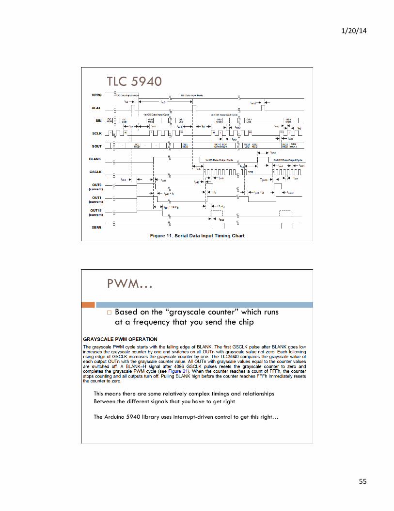
TLC 5940
1/20/14
55
TLC 5940
PWM…
¨ Based on the “grayscale counter” which runs at a frequency that you send the chip
This means there are some relatively complex timings and relationships Between the different signals that you have to get right The Arduino 5940 library uses interrupt-driven control to get this right…

1/20/14
56
PWM…
22
8196 8196
2
1 1
XLAT
Blank
Timer
TLC5940 Library

1/20/14
57
TLC5940 Library
TLC5940 Library

1/20/14
58
TLC5940 – setting the resistor
¨ One resistor (to GND) sets current for all channels
Min = 5ma Max = 120ma
TLC5940 Summary
¨ Easy to use – if you use the tlc5940 library!
Breakout board from Sparkfun $13

1/20/14
59
TLC5940 Examples
TLC5940 Examples

1/20/14
60
TLC5940 Summary
¨ Easy to use – if you use the tlc5940 library! ¨ Can also use for servo control
¤ Use the PWM channels to drive servos ¤ Remember power issues! ¤ Separate tlc5940 servo library ¤ Resets some timing to get
the servo timing right…
Breakout board from Sparkfun $13

1/20/14
61
TLC5940 Servo Example
1/20/14
62
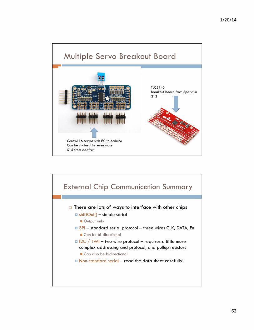
Multiple Servo Breakout Board
Control 16 servos with I2C to Arduino Can be chained for even more $15 from Adafruit
TLC5940 Breakout board from Sparkfun $13
External Chip Communication Summary
¨ There are lots of ways to interface with other chips ¤ shiftOut() – simple serial
n Output only
¤ SPI – standard serial protocol – three wires CLK, DATA, En n Can be bi-directional
¤ I2C / TWI – two wire protocol – requires a little more complex addressing and protocol, and pullup resistors n Can also be bidirectional
¤ Non-standard serial – read the data sheet carefully!

1/20/14
63
LED Driver Chips Summary
¨ STP08DP05 ¤ Drives 8 LEDs with constant-current sources ($1.82) ¤ SPI interface
¨ MAX 7219/7221 ¤ drives 8 digits of 7-segment display or 64 LEDs (8x8 array)
($9.95) ¤ Common-cathode LED arrays or digits – SPI interface
¨ TLC5940/5941 ¤ Drives 16 LEDs with each LED having 12 bits of PWM
brightness ($5.95) ¤ Complicated communication protocol ¤ Can also be used for multiple servos