Alphanumeric LCD infrared control via computer's parallel port

Interfacing Mobile Phone LCD to Parallel PortThe availability of high resolution LCD as a spare part of mobile phone has opened a new world of colourful display for electronics and computer interfacing hobbyists. You will be surprised to know that 16x2 character LCD is not available in the place I live whereas high resolution LCD of mobile phones can be found easily at very low prices.
Understanding the protocol for communicating with such LCD and writing programs to drive them can prove to be a very time consuming and frustrating job. Fortunately an open source project, serdisplib[1], exists that does the job for us.
Serdisplib is a project maintained by Wolfgang Astleitner and hosted at sourceforge.net. Started in July 2003 with support for only one LCD, this project has grown to add support for 25+ different LCD. It supports several mobile phone LCD, USB based LCD and OLED displays.
In this article, we will focus on setting up Nokia 6100 (S1D15G10 controller green connector) LCD to work with serdisplib. Then with some python scripting and 'multidisplay' (a tool shipped with serdisplib package), we will use our setup to create an application that will show alert message in the LCD screen when a new email arrives into a specified Gmail mailbox.
The discussion in this article only applies to Nokia 6100 LCD (S1D15G10 controller with green connector). However, other LCDs can easily be used for this purpose using the techniques discussed below with some minor changes. Support for Nokia 6100 LCD was added in serdisplib1.97.6 release[2].
Generating the voltages required by LCDThe LCD required two voltages – 7 V and 3.3 V (as given in LCD datasheet). We can use LM317 voltage regulator IC to generate these voltages. The circuit for generating desired voltage using LM317 is given in Fig. 1
Fig. 1: Circuit connection for LM317 to generate desired voltages
To obtain Vout = 6.8 V

R1 = 330 Ohm, R2 = 1.5 Kohm, Vin = 9V or 12 V
To obtain Vout = 2.8 V R1 = 330 Ohm, R2 = 470 Ohm, Vin = 5V
NOTE:
• R1 must be greater than 240 Ohm in all cases • You can calculate other combinations of R1 & R2 using Vout = 1.25 x ( 1 + R2 / R1 )
• The Vlogic (Pin 10) can be left unconnected. Connect some (I used two) 0.1uF ceramic capacitors between the Vout and GND (ground line) of the power supply, created using LM317, to prevent flickering of LCD display.
• Do not exceed the 3.3V limit for Vlcd as the LCD can be damaged above this voltage.
Preparing the LCD for connection to Parallel Port
Fig. 2: LCD connector
Fig. 3: LCD connected to X302 10 pin female connector mounted on PCB
The pin separation of LCD connector (X302 10 pin male connector) is very small making it impossible to solder wires directly to the pins. Hence, we can use the corresponding female connector (easily found in mobile repair shops) to connect wires from parallel port to the LCD. This male connector can be soldered to a PCB having tracks to match the pin separation (this is quite difficult to find. I used a 32pin uSOP IC tracks, see Fig. 2, to solder this connector). The pin numbers (printed on the green PCB of LCD connector) can be seen in Fig 2.

Connecting LCD to the Parallel Port
Fig. 4: Pin Diagram for LCD connector
Fig. 5: Circuit connection for connecting LCD to parallel port
NOTE:
• Be careful when connecting the lines. You can cause permanent damage to your parallel port or the LCD by wrong connection.
• Switch off your computer before connecting the LCD to the parallel port.
Connect the wires from LCD to parallel port as shown in Fig. 5. The power supply circuit created before should be used to supply required voltages to LCD [ Vlcd (Pin 5) = 2.8V, Vled+ (Pin 1) = 6.8V ]. You can test your LCD backlight by switching ON the power supply for 6.8V. Check the connections if the LCD backlight does not glow. Make sure that the ground of Parallel port is connected to the LCD ground and the power supply ground (ie: all of them have a common ground).
Display some test patternsDownload the package “serdisplib1.97.6” (Note that earlier versions do not support Nokia 6100 LCD) from http://serdisplib.sourceforge.net and extract the package. Build the package using:
[root@tlm serdisplib1.97.6]# ./configure
[root@tlm serdisplib1.97.6]# make
[root@tlm serdisplib1.97.6]# make install
Now you are ready to test your LCD. We will use the testserdisp tool provided by this library to test our LCD.
[root@tlm serdisplib1.97.6]# cd src
[root@tlm src]# ./testserdisp n N6100
enter 'help' to get help

>
Fig. 6: start of 'testserdisp'
Fig. 7: pattern 2
Fig. 8: pattern 0
At this point you should see something like Fig. 6
If you see the welcome screen (with the LCD pixel size ie: 130x130 as shown in Fig. 6), then you have successfully setup your LCD. You can test other patterns issuing “p 0....9” (pattern command) in the command prompt displayed by testserdisp.
If you don't see any output in your LCD, you can follow the Debugging steps discussed below.
DebuggingI had spent 3 weeks debugging my circuit (and the serdisplib code which did not support Nokia 6100 LCD at that time) and at last I found that I had connected the LCD just the other way. Yes, this is possible with the connector that these LCD have. Fortunately, this did not damage my LCD.
You can follow some of these debugging tips to find out the problem in your circuit.
1. Make sure that the pins of LCD connector are identified correctly. If you connect it the other way, Pin1 will get connected to the line for Pin 6 and Pin 10 will get connected to the line for Pin 4. The pin numbering given in the Fig. 4 is for Nokia 6100 LCD with green connector. Other connectors can have different pin assignments.
2. Attach two LED to the SDATA line (Pin 8) and SCLK line (Pin 7). Make sure that these LEDs blink (very fast) when you invoke the command “./testserdisp n N6100” in your computer. If these do not blink at all, check the connection of wires to your parallel port. Check that these lines are connected to correct pins of parallel port [ie: SDATA > D0 (Pin 2 of Parallel Port), SCLK > D1 (Pin 3 of Parallel Port), and so on. ]. Verify your connection with the circuit shown in Fig 5.
3. Using a Voltmeter, check that you are applying correct voltages to the Vlcd pin (2.8V to 3.3V) and Vled(+) pin (6.5V to 7V). Vlcd pin voltage should never exceed 3.3V limit as it might permanently damage the LCD.

4. Make sure that the ground of Parallel port is connected to the LCD ground and the power supply ground (ie: all of them have a common ground).
5. Verify the connection between parallel port connector and the LCD pins using a continuity tester (switch off your circuit and disconnect the parallel port connection).
Assuming that you have successfully setup the LCD and 'testserdisp' is working, we are ready to do something useful with this setup.
Gmail To LCD applicationWith some python scripting and 'multidisplay' (shipped with serdisplib package), we will use our setup to create an application that will show alert message in the LCD screen when a new email arrives into any specified Gmail mailbox. See Fig. 9 to have a glimpse of the final application.
NOTE: You will require to enable “POP Download” feature for your GMAIL inbox (disabled by default).
Login into your GMAIL and goto 'Settings' > 'Forwarding and POP' and then select the radio button for “Enable POP only for mail that arrives from now on” option. Save you mailbox settings. Now you can access new emails arriving into you mailbox using a POP client.
Fig. 9: Notification in LCD when new email arrives
Now, let us discuss about the block diagram of our application shown in Fig. 10.
Fig. 10: Block diagram of GmailToLCD application
The python script 'gmailtolcd.py' queries the Gmail POP server to check if any new email has arrived in the mailbox. When new mail(s) arrive, it uses the template image to create a new image (gmailbox.png)

which contains the information about new email(s). The message details (From and Subject) are displayed only for the newest email. 'multidisplay' tool is then used to display the image (gmailbox.png) on the LCD screen.
NOTE:
'multidisplay' is a tool shipped with serdisplib1.97.6 package (in serdisplib1.97.6/tools/multidisplay). It is used to display images and text using serdisplib. You must install libgd[3] >= 2 ( GD is an open source code library for the dynamic creation of images by programmers. GD creates PNG, JPEG and GIF images, among other formats.) before compiling serdisplib. Multidisplay tool will NOT work if serdisplib is compiled without installing libgd.
To verify that, serdisplib is compiled with libgd support, check that configure script produces the result as shown below:
[root@tlm serdisplib1.97.6]# ./configure
checking build system type... i686pclinuxgnu
................
................
supported features
==================
* libgd >= 2 support ... yes
................
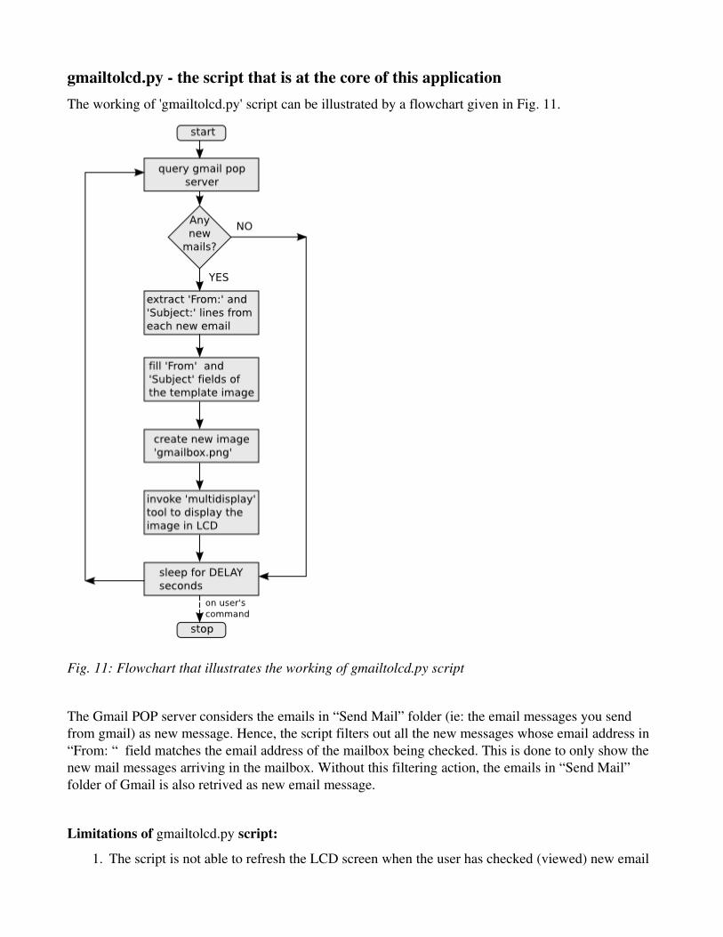
gmailtolcd.py the script that is at the core of this applicationThe working of 'gmailtolcd.py' script can be illustrated by a flowchart given in Fig. 11.
Fig. 11: Flowchart that illustrates the working of gmailtolcd.py script
The Gmail POP server considers the emails in “Send Mail” folder (ie: the email messages you send from gmail) as new message. Hence, the script filters out all the new messages whose email address in “From: “ field matches the email address of the mailbox being checked. This is done to only show the new mail messages arriving in the mailbox. Without this filtering action, the emails in “Send Mail” folder of Gmail is also retrived as new email message.
Limitations of gmailtolcd.py script:
1. The script is not able to refresh the LCD screen when the user has checked (viewed) new email

from the web interface of Gmail. It keeps on showing the new message alert on LCD screen until another new message arrives.
When new emails are retrieved from the Gmail POP server, they are marked as read by the server (but appears as NEW email in the gmail web interface). I did not find any technique to inform the script when the user reads new messages from the web interface.
2. There should be some mechanism to turn off the power of LCD backlight when no new messages are present in the mailbox. The LCD backlight should blink, in order to attract the attention of user, when new email arrives in the mailbox. This can be done by using one additional pin of parallel port to switch the supply of LCD backlight using a BC547 transistor.
Installation of GmailToLCD1. Install libgd[3] >= 2 library (skip this step if you already have this library). Download tar.gz
archive of libgd (version greater than 2.0) .
Extract the archive.
[root@tlm mydir]# tar zxvf gd2.0.35.tar.gz
[root@tlm mydir]# cd gd2.0.35
[root@tlm gd2.0.35]# ./configure && make && make install
2. Install serdisplib[1](version greater or equal to 1.97.6) library from the project's download site. Extract the archive.
[root@tlm mydir]# tar zxvf serdisplib1.97.6.tar.gz
[root@tlm mydir]# cd serdisplib1.97.6
[root@tlm serdisplib1.97.6]# ./configure && make && make install
NOTE: Ensure that ./configure script produces the following output libgd >= 2 support ... yes
3. Copy the GmailToLCD archives (tar.gz format, zip format), to "serdisplib1.97.6/tools/multidisplay" directory. Extract the contents of this archive there.
[root@tlm mydir]# cp gmailtolcdv1.tar.gz serdisplib1.97.6/tools/
[root@tlm mydir]# cd serdisplib1.97.6/tools/
[root@tlm tools]# tar zxvf gmailtolcdv1.tar.gz
app_template.png
gmailtolcd.py
LiberationMonoRegular.ttf
README
4. Switch on the power supply to LCD.
5. Verify that you have python >= 2.4.0 installed in your system. Execute the python script 'gmailtolcd.py'

[root@tlm tools]# python
Python 2.4.3 (#1, Oct 1 2006, 18:00:19)
[GCC 4.1.1 20060928 (Red Hat 4.1.128)] on linux2
Type "help", "copyright", "credits" or "license" for more information.
>>> {{ Press Ctrl + D to exit }}
[root@tlm tools]# python gmailtolcd.py [email protected] YOUR_GMAIL_PASSWORD
Fig. 12: LCD screen when gmailtolcd.py script is executed
You should see a welcome screen as shown in Fig. 12. The LCD screen will be updated automatically when a new email arrives in your Gmail mailbox.[A]
Press Ctrl + C key to terminate the gmailtolcd.py script.
[A] NOTE: see Limitations of gmailtolcd.py in previous section.
Installation Notes:
The gmailtolcd application was successfully tested in PCQLinux 2006 (Desktop Installation) and Fedora Core 7.
● PCQLinux 2006 does not contain the libgd[3]>= 2 library. So you will require to manually install this library, as descibed in previous section, before installing “serdisplib1.97.6” library.
● Fedora Core 7 comes bundled with libgd[3]>= 2 library. So you will only require to install “serdisplib1.97.6” library.

GmailToLCD in Action (Photos)
Photographs that capture GmailToLCD in action

Miscellaneous photographs taken during testing of multidisplay tool. My electronics workbench setup
References
• Python Online Documentation • Python Imaging Library Handbook – Online Version • Python Online Documentation POP3 example • serdisplib Nokia 6100 page
Permissions
• Permission to use Gmail logo for illustration purpose obtained from Google Permissions[4] Site • Font used in GmailToLCD is Liberation Mono True Type Font[5](GPL Font released by Redhat)
URL References:[1] serdisplib project page
http://serdisplib.sourceforge.net
[2] serdisplib page for “s1d15g10 series” lcd http://serdisplib.sourceforge.net/ser/nokcol_15g10.html
[3] libgd project page
http://www.libgd.org/
[4] Google Permissions
http://www.google.com.np/permissions/index.html
[5] GPL Liberation Fonts
http://www.kdelook.org/content/show.php/Redhat+Liberation+Fonts?content=58724


![C parallel port [Compatibility Mode].pdf](https://static.fdocuments.in/doc/165x107/577cd7071a28ab9e789ddef2/c-parallel-port-compatibility-modepdf.jpg)