
Interfacing diagram with SUN DR2 rev 02 - SunSDR.eu · Interfacing diagram with SUN DR2 CW Skimmer...
54
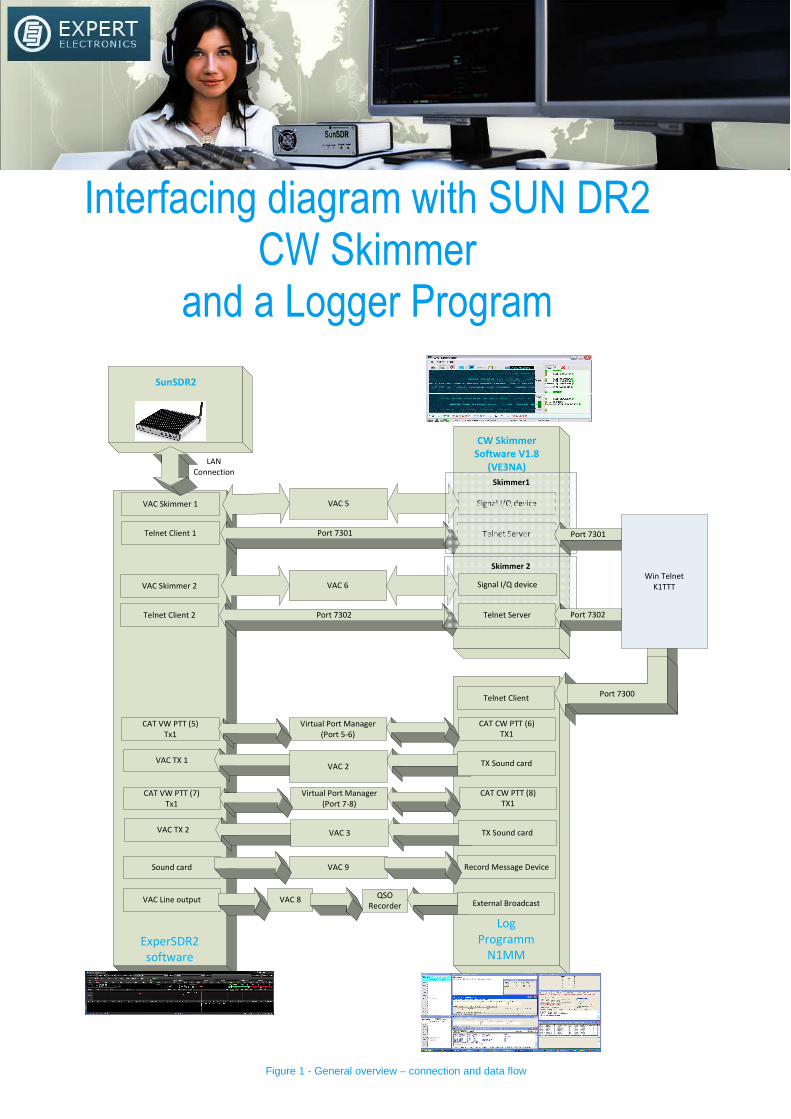
Interfacing diagram with SUN DR2 CW Skimmer and a Logger Program VAC Skimmer 1 Telnet Client 1 CAT VW PTT (5) Tx1 SunSDR2 VAC 5 CW Skimmer Software V1.8 (VE3NA) Signal I/Q device Telnet Server Log Programm N1MM Telnet Client CAT CW PTT (6) TX1 Virtual Port Manager (Port 5-6) Port 7300 Port 7301 LAN Connection ExperSDR2 software Record Message Device VAC TX 1 Sound card VAC Line output VAC 9 VAC 8 QSO Recorder VAC Skimmer 2 Telnet Client 2 VAC 6 Port 7302 Skimmer 2 Signal I/Q device Telnet Server Port 7302 Skimmer1 Port 7301 Win Telnet K1TTT VAC 2 TX Sound card CAT VW PTT (7) Tx1 CAT CW PTT (8) TX1 Virtual Port Manager (Port 7-8) VAC TX 2 VAC 3 TX Sound card External Broadcast Figure 1 - General overview – connection and data flow
Transcript of Interfacing diagram with SUN DR2 rev 02 - SunSDR.eu · Interfacing diagram with SUN DR2 CW Skimmer...
Interfacing diagram with SUN DR2
CW Skimmer and a Logger Program
VAC Skimmer 1
Telnet Client 1
CAT VW PTT (5)
Tx1
SunSDR2
VAC 5
CW Skimmer
Software V1.8
(VE3NA)
Signal I/Q device
Telnet Server
Log
Programm
N1MM
Telnet Client
CAT CW PTT (6)
TX1
Virtual Port Manager
(Port 5-6)
Port 7300
Port 7301
LAN
Connection
ExperSDR2
software
Record Message Device
VAC TX 1
Sound card
VAC Line output
VAC 9
VAC 8QSO
Recorder
VAC Skimmer 2
Telnet Client 2
VAC 6
Port 7302
Skimmer 2
Signal I/Q device
Telnet Server Port 7302
Skimmer1
Port 7301
Win Telnet
K1TTT
VAC 2 TX Sound card
CAT VW PTT (7)
Tx1
CAT CW PTT (8)
TX1
Virtual Port Manager
(Port 7-8)
VAC TX 2 VAC 3 TX Sound card
External Broadcast
Figure 1 - General overview – connection and data flow
2
Table of Contents
1 Introduction .......................................................................................................... 5
2 Installation procedure CW Skimmer and Expert SDR2 ........................................ 6
2.1 Virtual Audio cable VAC .......................................................................................................... 6
2.1.1 Installation ................................................................................................................................ 6
2.1.2 Configuration ............................................................................................................................ 8
2.1.3 Virtual cable creation ............................................................................................................... 9
2.2 VSP Manager .......................................................................................................................... 10
2.2.1 Installation .............................................................................................................................. 10
2.2.2 Configuration .......................................................................................................................... 15
2.3 CW skimmer ........................................................................................................................... 18
2.3.1 Installation .............................................................................................................................. 18
2.3.2 Configuration .......................................................................................................................... 21
2.4 Win TelnetX ............................................................................................................................. 25
2.4.1 Introduction ............................................................................................................................ 25
2.4.2 Installation .............................................................................................................................. 25
2.4.3 Configuration .......................................................................................................................... 25
2.5 Expert SDR2 ........................................................................................................................... 33
2.5.1 Installation .............................................................................................................................. 33
2.5.2 Configurations ........................................................................................................................ 37
3 Contest Logger configuration ............................................................................. 44
3.1 Introduction ............................................................................................................................ 44
3.2 N1MM Software ...................................................................................................................... 44
3.3 SO1V configuration ................................................................................................................ 45
3.4 SO2R configuration ............................................................................................................... 46
3.5 TR4W ....................................................................................................................................... 49
3.5.1 Installation .............................................................................................................................. 49
3.5.2 Configuration .......................................................................................................................... 50
3.6 LogHX ...................................................................................................................................... 51
3.6.1 Installation .............................................................................................................................. 51
3.6.2 Configuration .......................................................................................................................... 54
3
Table of Figures
Figure 1 - General overview – connection and data flow .............................................................................. 1 Figure 2 - Installer .......................................................................................................................................... 6 Figure 3 - Virtual Audio Cable Installation ..................................................................................................... 6 Figure 4 - License Agreement ....................................................................................................................... 7 Figure 5 - VAC Path Location ........................................................................................................................ 7 Figure 6 - VAC Process Installation............................................................................................................... 7 Figure 7 - VAC - Installation Completed ........................................................................................................ 8 Figure 8 - Starting VAC Software .................................................................................................................. 8 Figure 9 - VAC Window ................................................................................................................................. 8 Figure 10 - VAC Cable Creation .................................................................................................................... 9 Figure 11 – VSPM Installer .......................................................................................................................... 10 Figure 12 - VSPM Setup .............................................................................................................................. 10 Figure 13 - VSPM License Agreement ........................................................................................................ 11 Figure 14 - VSPM Path Installation ............................................................................................................. 11 Figure 15 - VSPM Folder Creation .............................................................................................................. 12 Figure 16 - VSPM Icon Creation .................................................................................................................. 12 Figure 17 - VSPM Resume Installation ....................................................................................................... 13 Figure 18 - VSPM Installation Process ........................................................................................................ 13 Figure 19 - VSPM Installation Completed ................................................................................................... 14 Figure 20 - Starting VSP Mgr ...................................................................................................................... 15 Figure 21 - VSP Mgr - Port Creation ........................................................................................................... 15 Figure 22 - VSP Mgr - Virtual Port displayed .............................................................................................. 16 Figure 23 - CW Skimmer Installer ............................................................................................................... 18 Figure 24 - CW Skimmer Setup ................................................................................................................... 18 Figure 25 - CW Skimmer License Agreement ............................................................................................. 19 Figure 26 - CW Skimmer Destination .......................................................................................................... 19 Figure 27 - CW Skimmer Installation Process ............................................................................................. 20 Figure 28 - CW Skimmer Installation Completed ........................................................................................ 20 Figure 29 - CW Skimmer Main Window ...................................................................................................... 21 Figure 30 - CW Skimmer View Tab Sheet - Setting .................................................................................... 21 Figure 31 - CW Skimmer Setting - Radio Tab Sheet .................................................................................. 22 Figure 32 - CW Skimmer Setting - Audio Tab Sheet................................................................................... 23 Figure 33 - CW Skimmer Setting - Telnet Tab Sheet .................................................................................. 24 Figure 35 – Win TelnetX general windows .................................................................................................. 25 Figure 35 – Win TelnetX Setup Rx connect ................................................................................................ 25 Figure 35 – Win TelnetX Rx Net connection Setup ..................................................................................... 26 Figure 35 – Win TelnetX RX net connect script .......................................................................................... 27 Figure 35 – Win TelnetX general windows Port 7300 created .................................................................... 27 Figure 35 – Win TelnetX Setup Network connect ....................................................................................... 28 Figure 35 – Win TelnetX Setup Network connection setup ......................................................................... 28 Figure 35 – Win TelnetX Setup Network connection script setup ............................................................... 29 Figure 35 – Win TelnetX Port created ......................................................................................................... 29 Figure 35 – Win TelnetX Route declaration ................................................................................................ 30 Figure 35 – Win TelnetX Route display ....................................................................................................... 30 Figure 35 – Win TelnetX routing 7301 to 7300 ............................................................................................ 31 • Figure 35 – Win TelnetX routing 7301& 7302 to 7300 ............................................................ 31 Figure 35 – Win TelnetX connections ......................................................................................................... 32 Figure 35 – Win TelnetX routing 7301 to 7300 result .................................................................................. 32 Figure 34 - ExpertSDR2 Installer ................................................................................................................. 33 Figure 35 - ExpertSDR2 - Setup .................................................................................................................. 33 Figure 36 - ExpertSDR2 - Setup Installation ............................................................................................... 34 Figure 37 - ExpertSDR2 Path Install ........................................................................................................... 34
4
Figure 38 - ExpertSDR2 - Short Cut Creation ............................................................................................. 35 Figure 39 - ExpertSDR2 - Resume Install ................................................................................................... 35 Figure 40 - ExpertSDR2 - Install Process ................................................................................................... 36 Figure 41 - ExpertSDR2 – Install Completed .............................................................................................. 36 Figure 42 - ExpertSDR2 - Main Window ..................................................................................................... 37 Figure 43 - ExpertSDR2 – Option Folder .................................................................................................... 37 Figure 44 - ExpertSDR2 - Option – Device Folder - Sample Rate Configuration ....................................... 38 Figure 45 - ExperSDR2 – Receiver 1CAT Configuration ............................................................................ 39 Figure 45 - ExperSDR2 – Receiver 2CAT Configuration ............................................................................ 39 Figure 46 - ExpertSDR2 - Option – CW Skimmer Folder – Port Configuration........................................... 40 Figure 47 - ExpertSDR2 - Option – CW Skimmer Folder – RX IQ Driver Configuration ............................. 40 Figure 48 - ExpertSDR2 - Option – CW Skimmer Folder – RX IQ Output Configuration ........................... 41 Figure 49 - ExpertSDR2 - Option – CW Skimmer Folder – RX IQ Validation ............................................. 41 Figure 50 - ExpertSDR2 - Option – CW Skimmer Folder – Receiver 1 Parameters Validation .................. 41 Figure 50 - ExpertSDR2 - Option – CW Skimmer Folder – Receiver 2 Parameters Validation .................. 42 Figure 51 - ExpertSDR2 - Option – Futures folder - Started Programs ...................................................... 43 Figure 52 - ExpertSDR2 - Option – Main window - Skimmer Declaration................................................... 43 Figure 53 - N1MM Software - Config Ports, Mode, Audio ........................................................................... 44 Figure 54 - N1MM Com Configuration......................................................................................................... 45 .Figure 55 - N1MM Software - Config - Telnet Cluster Windows Location .................................................. 47 Figure 56 - N1MM Software - Telnet Window - Skimmer Declaration ........................................................ 48 Figure 57 - Hardware Window - Skimmer Declaration ................................................................................ 48 Figure 58 - Telnet Data Flow ....................................................................................................................... 49
5
1 Introduction
The data flow I/Q from the Expert SDR program is transmitted through a virtual audio cable interface to the CW Skimmer software for decoding the signal in the bandwidth. In parallel, The Sun SDR2 is connected via a telnet connection on the telnet server located on CW Skimmer software. CW Skimmer software manage also a telnet connection bridge to the logger program. The CAT connection between the SUN SDR2 and the logger program are managed through a virtual Port manager. Software used for this task are available to the links below.
Expert Electronic software
VAC (Virtual Audio Cable)
CW Skimmer
VSPM (Virtual Serial Port Manager) by Steve Nance K5FR
Win TelnetX by David Robbins K1TTT
Logger software
- N1MM software
- TR4W
- LogHX And others…

6
2 Installation procedure CW Skimmer and Expert
SDR2
It’s necessary to install VAC (Virtual Audio cable) on your computer for managing the Data flow.
2.1 Virtual Audio cable VAC
2.1.1 Installation
After downloading the VAC software click on install icon
Figure 2 - Installer
� Continue by a click on Yes
Figure 3 - Virtual Audio Cable Installation
7
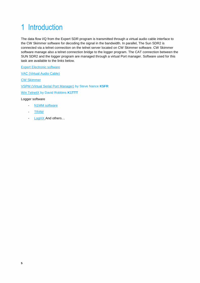
� Then click on I accept
Figure 4 - License Agreement
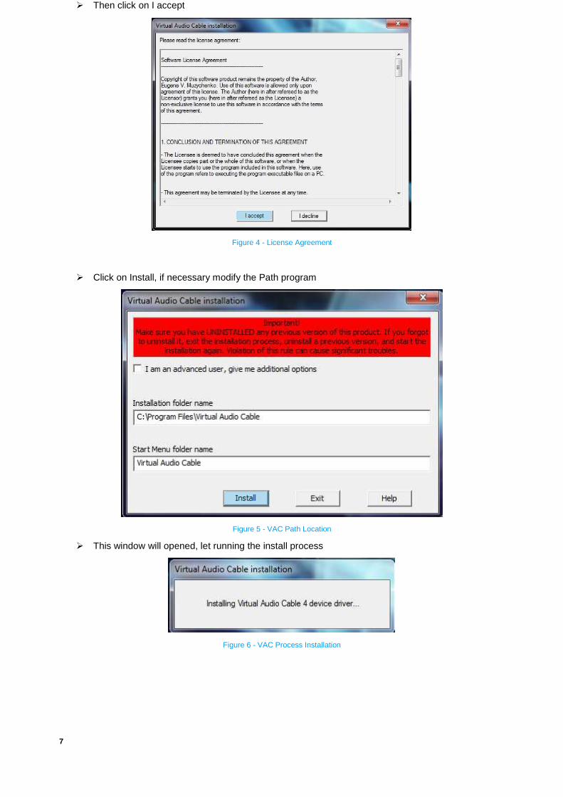
� Click on Install, if necessary modify the Path program
Figure 5 - VAC Path Location
� This window will opened, let running the install process
Figure 6 - VAC Process Installation
8
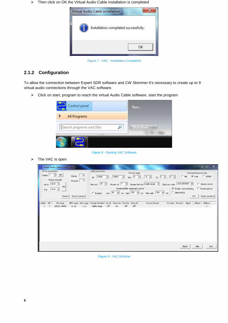
� Then click on OK the Virtual Audio Cable installation is completed
Figure 7 - VAC - Installation Completed
2.1.2 Configuration
To allow the connection between Expert SDR software and CW Skimmer it’s necessary to create up to 9 virtual audio connections through the VAC software.
� Click on start, program to reach the virtual Audio Cable software, start the program
Figure 8 - Starting VAC Software
� The VAC is open
Figure 9 - VAC Window
9
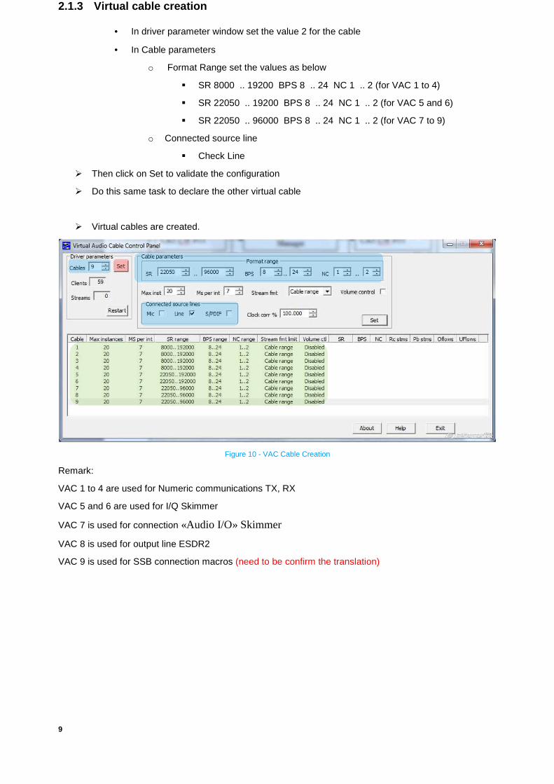
2.1.3 Virtual cable creation
• In driver parameter window set the value 2 for the cable
• In Cable parameters
o Format Range set the values as below
� SR 8000 .. 19200 BPS 8 .. 24 NC 1 .. 2 (for VAC 1 to 4)
� SR 22050 .. 19200 BPS 8 .. 24 NC 1 .. 2 (for VAC 5 and 6)
� SR 22050 .. 96000 BPS 8 .. 24 NC 1 .. 2 (for VAC 7 to 9)
o Connected source line
� Check Line
� Then click on Set to validate the configuration
� Do this same task to declare the other virtual cable
� Virtual cables are created.
Figure 10 - VAC Cable Creation
Remark:
VAC 1 to 4 are used for Numeric communications TX, RX
VAC 5 and 6 are used for I/Q Skimmer
VAC 7 is used for connection «Audio I/O» Skimmer
VAC 8 is used for output line ESDR2
VAC 9 is used for SSB connection macros (need to be confirm the translation)
10
2.2 VSP Manager
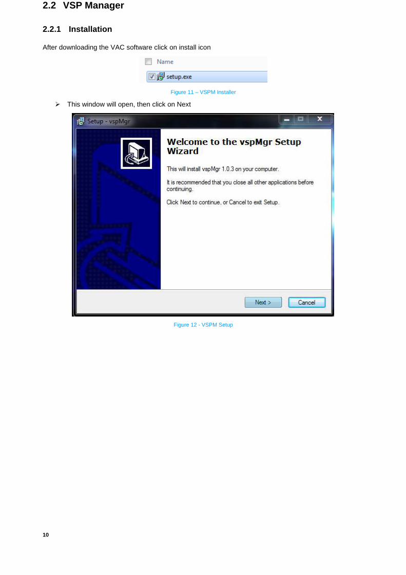
2.2.1 Installation
After downloading the VAC software click on install icon
Figure 11 – VSPM Installer
� This window will open, then click on Next
Figure 12 - VSPM Setup
11
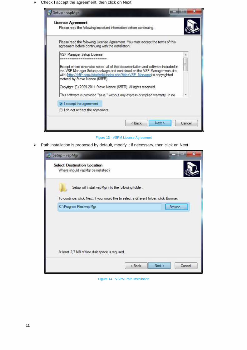
� Check I accept the agreement, then click on Next
Figure 13 - VSPM License Agreement
� Path installation is proposed by default, modify it if necessary, then click on Next
Figure 14 - VSPM Path Installation
12
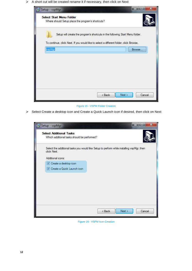
� A short cut will be created rename it if necessary, then click on Next
Figure 15 - VSPM Folder Creation
� Select Create a desktop icon and Create a Quick Launch icon if desired, then click on Next
Figure 16 - VSPM Icon Creation

13
� Setting information’s are displayed before installation, Click on install
Figure 17 - VSPM Resume Installation
� Let running the installation process
Figure 18 - VSPM Installation Process
14
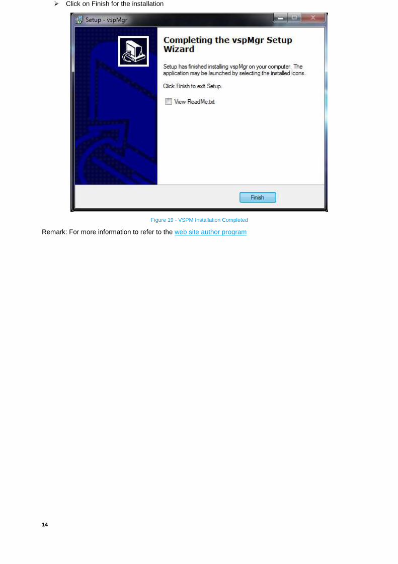
� Click on Finish for the installation
Figure 19 - VSPM Installation Completed
Remark: For more information to refer to the web site author program
15
2.2.2 Configuration
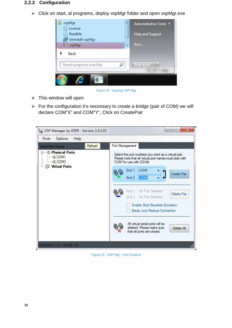
� Click on start, al programs, deploy vspMgr folder and open vspMgr.exe
Figure 20 - Starting VSP Mgr
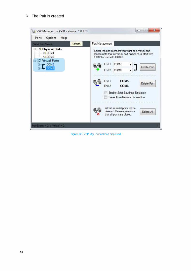
� This window will open
� For the configuration it’s necessary to create a bridge (pair of COM) we will declare COM”X” and COM”Y”, Click on CreatePair
Figure 21 - VSP Mgr - Port Creation
16
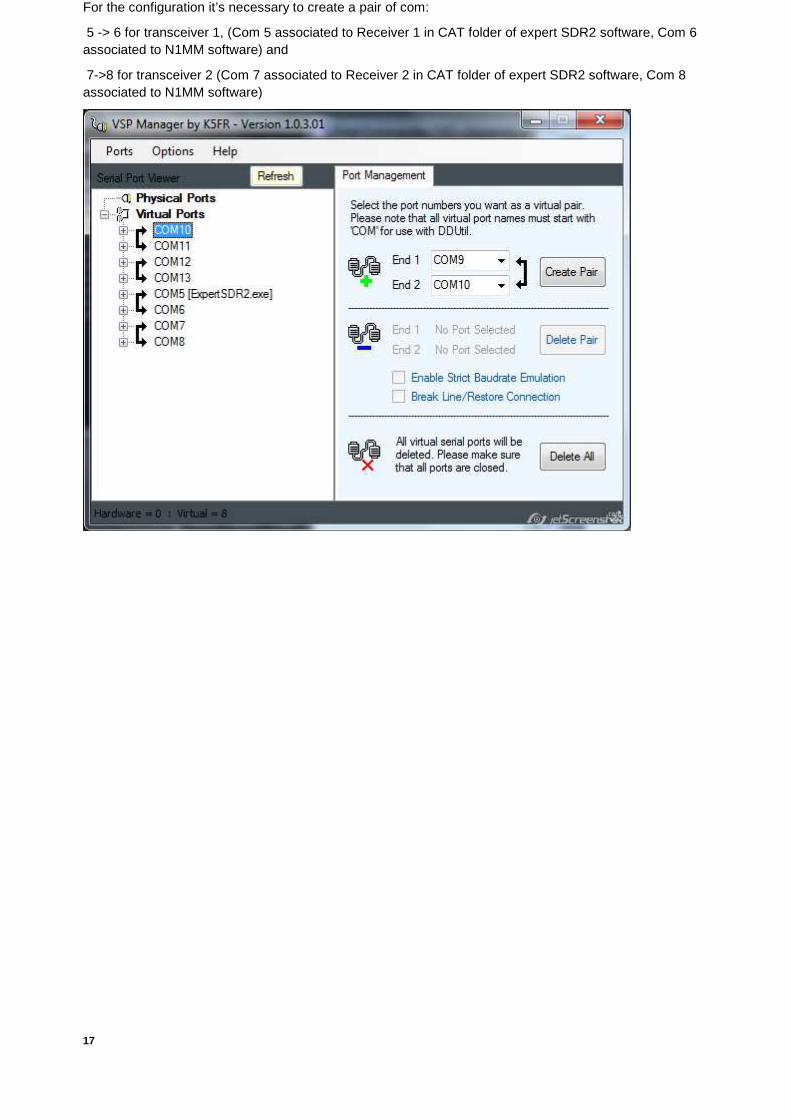
� The Pair is created
Figure 22 - VSP Mgr - Virtual Port displayed
17
For the configuration it’s necessary to create a pair of com:
5 -> 6 for transceiver 1, (Com 5 associated to Receiver 1 in CAT folder of expert SDR2 software, Com 6 associated to N1MM software) and
7->8 for transceiver 2 (Com 7 associated to Receiver 2 in CAT folder of expert SDR2 software, Com 8 associated to N1MM software)
18
2.3 CW skimmer
2.3.1 Installation
� After downloading the CW Skimmer software click on Setup.exe
Figure 23 - CW Skimmer Installer
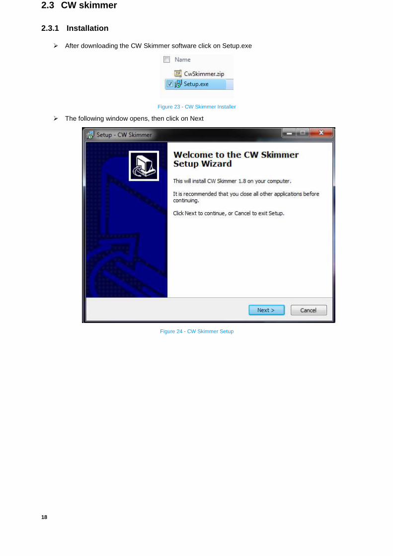
� The following window opens, then click on Next
Figure 24 - CW Skimmer Setup
19
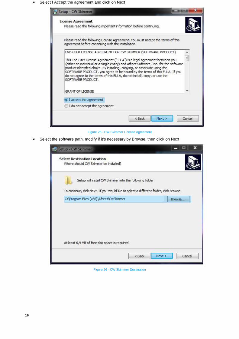
� Select I Accept the agreement and click on Next
Figure 25 - CW Skimmer License Agreement
� Select the software path, modify if it’s necessary by Browse, then click on Next
Figure 26 - CW Skimmer Destination
20
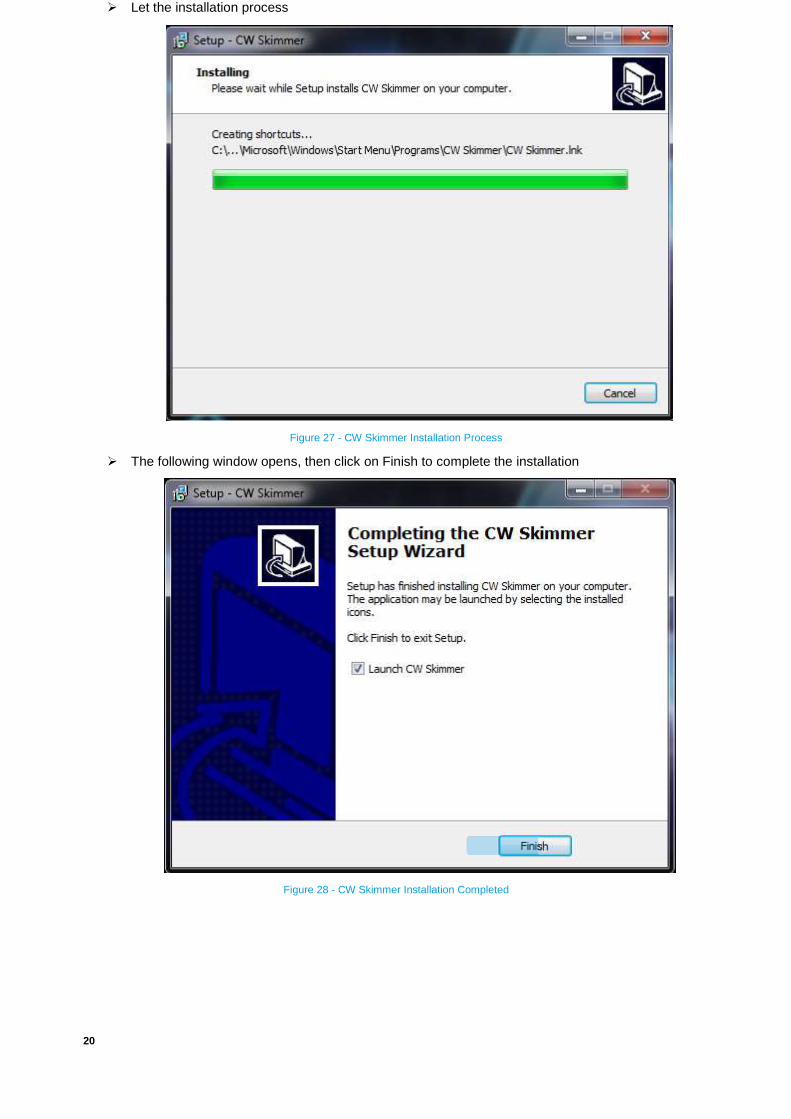
� Let the installation process
Figure 27 - CW Skimmer Installation Process
� The following window opens, then click on Finish to complete the installation
Figure 28 - CW Skimmer Installation Completed
21
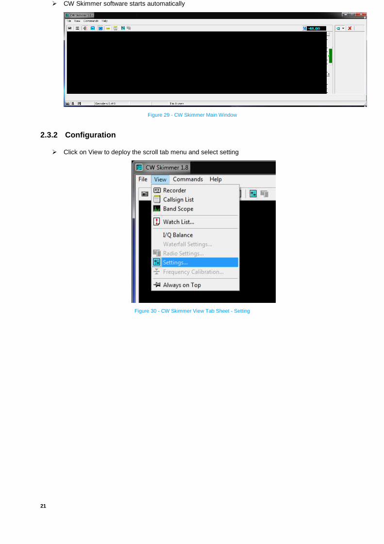
� CW Skimmer software starts automatically
Figure 29 - CW Skimmer Main Window
2.3.2 Configuration
� Click on View to deploy the scroll tab menu and select setting
Figure 30 - CW Skimmer View Tab Sheet - Setting
22
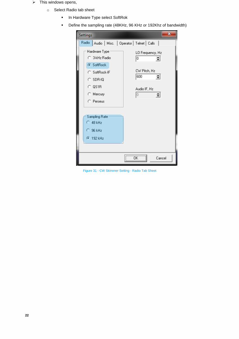
� This windows opens,
o Select Radio tab sheet
� In Hardware Type select SoftRok
� Define the sampling rate (48KHz, 96 KHz or 192Khz of bandwidth)
Figure 31 - CW Skimmer Setting - Radio Tab Sheet
23
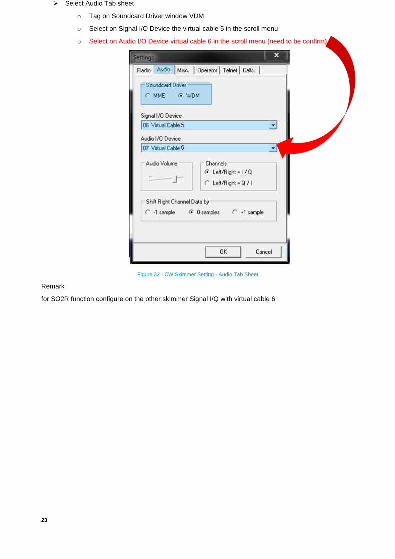
� Select Audio Tab sheet
o Tag on Soundcard Driver window VDM
o Select on Signal I/O Device the virtual cable 5 in the scroll menu
o Select on Audio I/O Device virtual cable 6 in the scroll menu (need to be confirm)
Figure 32 - CW Skimmer Setting - Audio Tab Sheet
Remark
for SO2R function configure on the other skimmer Signal I/Q with virtual cable 6
24
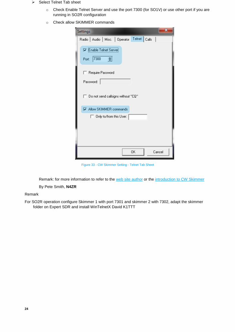
� Select Telnet Tab sheet
o Check Enable Telnet Server and use the port 7300 (for SO1V) or use other port if you are running in SO2R configuration
o Check allow SKIMMER commands
Figure 33 - CW Skimmer Setting - Telnet Tab Sheet
Remark: for more information to refer to the web site author or the introduction to CW Skimmer
By Pete Smith, N4ZR
Remark
For SO2R operation configure Skimmer 1 with port 7301 and skimmer 2 with 7302, adapt the skimmer folder on Expert SDR and install WinTelnetX David K1TTT

25
2.4 Win TelnetX
2.4.1 Introduction
This software is only used 2 skimmer for SO2R operation
2.4.2 Installation
Download the WinTelenetX from the K1TTT website (http://www.k1ttt.net/software.html) and unzip the folder
2.4.3 Configuration
The aim of this software is to combine 2 ports in another port. This software is able to root the 2 skimmers port in a general port for a general telnet
• Start the software
Figure 34 – Win TelnetX general windows
• Create a new connection (port 7300)
o Click on setup
o Select Add new
o Select Rx Network Connect
Figure 35 – Win TelnetX Setup Rx connect

26
• This windows will open
• Change Host Name or IP by 127.0.0.1
• Change the port to assign the port 7300
• Change the Name to 7300
• In Port data type deploy to select Direct
• Click on OK
Figure 36 – Win TelnetX Rx Net connection Setup
27
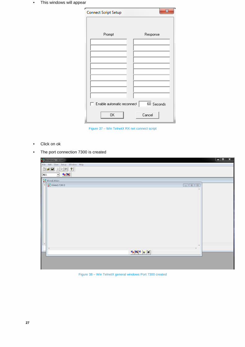
• This windows will appear
Figure 37 – Win TelnetX RX net connect script
• Click on ok
• The port connection 7300 is created
Figure 38 – Win TelnetX general windows Port 7300 created
28
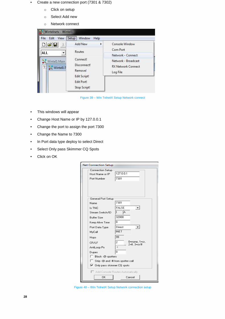
• Create a new connection port (7301 & 7302)
o Click on setup
o Select Add new
o Network connect
Figure 39 – Win TelnetX Setup Network connect
• This windows will appear
• Change Host Name or IP by 127.0.0.1
• Change the port to assign the port 7300
• Change the Name to 7300
• In Port data type deploy to select Direct
• Select Only pass Skimmer CQ Spots
• Click on OK
Figure 40 – Win TelnetX Setup Network connection setup

29
• Tag Enable automatic reconnect
Figure 41 – Win TelnetX Setup Network connection script setup
• Then click on OK
• The 7301 connection is created
• Do one more time the procedure to create the port 7302
Remark:
After reorganization windows the result is shown below with port 7300, 7301 and 7302 created
Figure 42 – Win TelnetX Port created
30
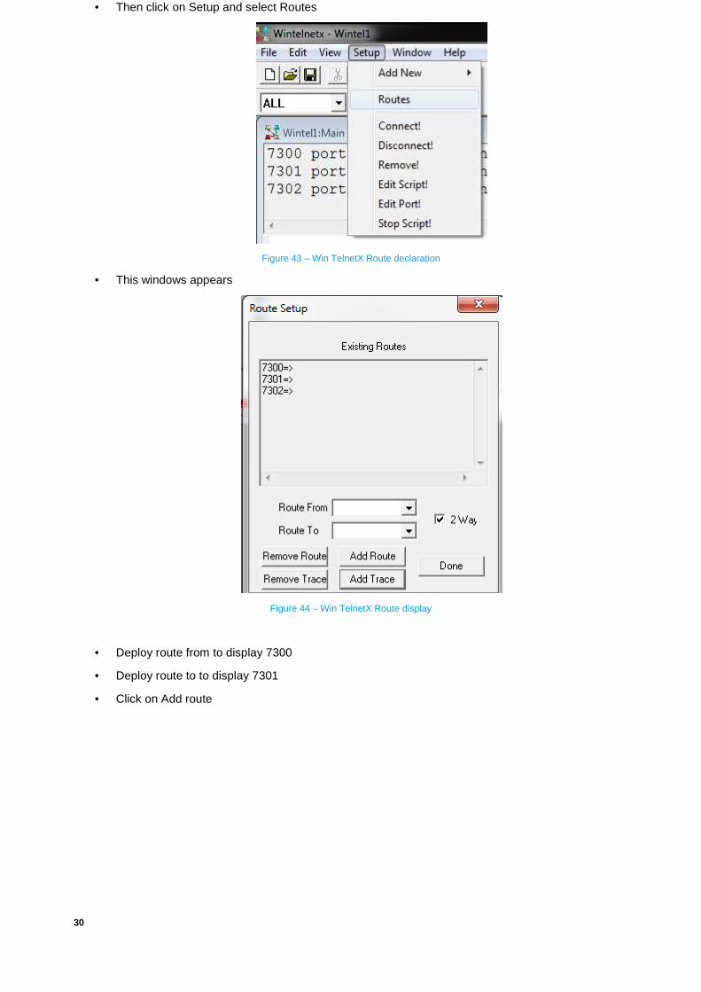
• Then click on Setup and select Routes
Figure 43 – Win TelnetX Route declaration
• This windows appears
Figure 44 – Win TelnetX Route display
• Deploy route from to display 7300
• Deploy route to to display 7301
• Click on Add route
31
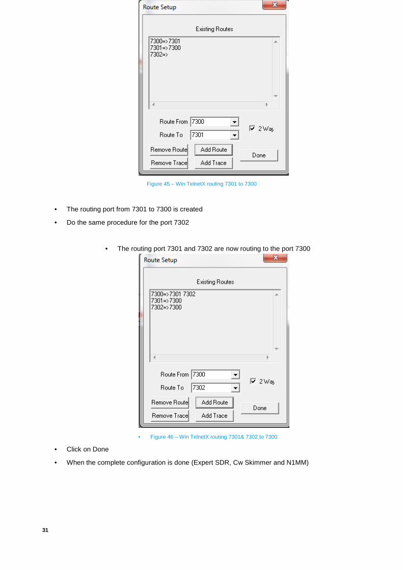
Figure 45 – Win TelnetX routing 7301 to 7300
• The routing port from 7301 to 7300 is created
• Do the same procedure for the port 7302
• The routing port 7301 and 7302 are now routing to the port 7300
• Figure 46 – Win TelnetX routing 7301& 7302 to 7300
• Click on Done
• When the complete configuration is done (Expert SDR, Cw Skimmer and N1MM)
32
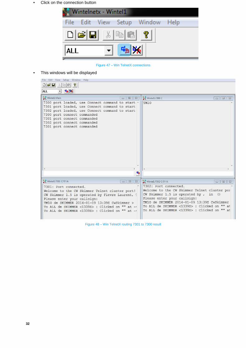
• Click on the connection button
Figure 47 – Win TelnetX connections
• This windows will be displayed
Figure 48 – Win TelnetX routing 7301 to 7300 result

33
2.5 Expert SDR2
2.5.1 Installation
� After downloading the Expert SDR2 software click on the installer.exe
Figure 49 - ExpertSDR2 Installer
� The following window opens, Select the language and then click on Next
Figure 50 - ExpertSDR2 - Setup
34
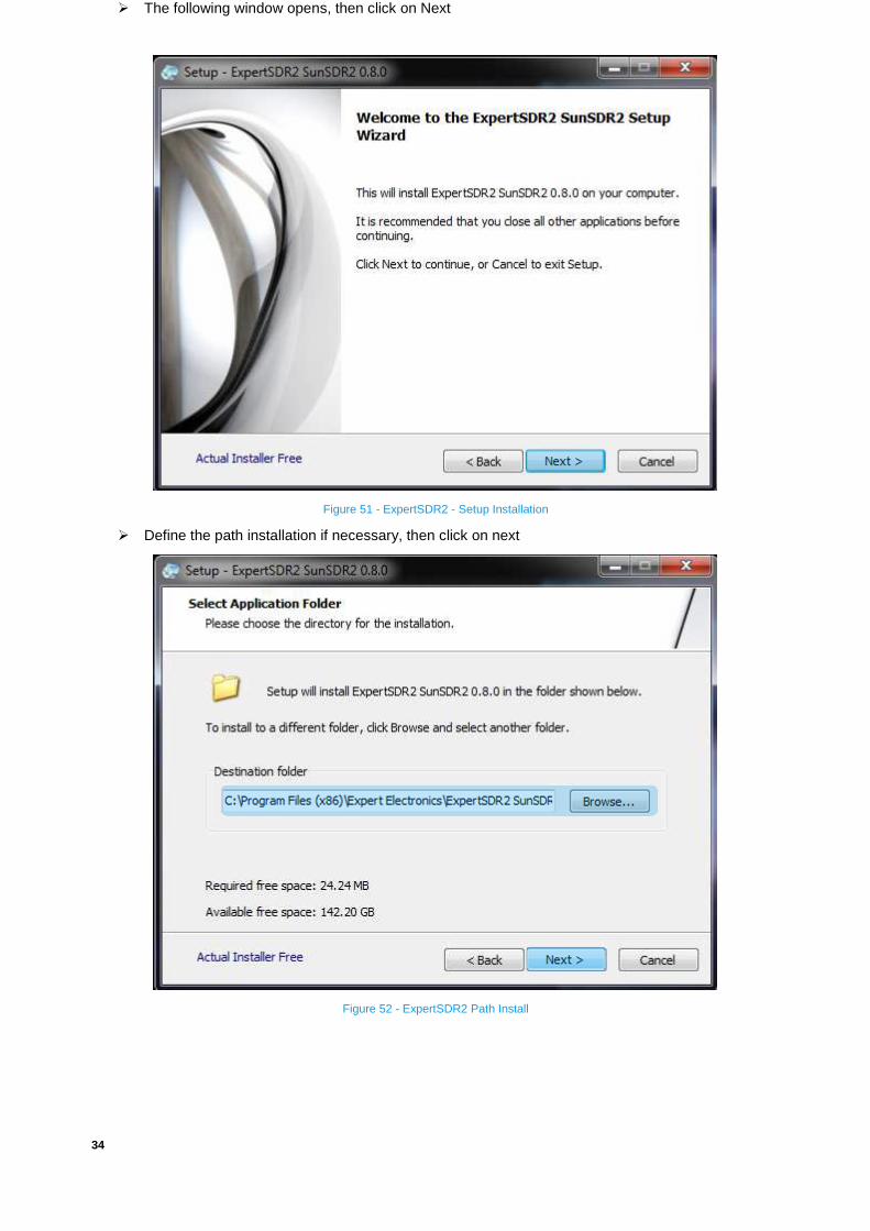
� The following window opens, then click on Next
Figure 51 - ExpertSDR2 - Setup Installation
� Define the path installation if necessary, then click on next
Figure 52 - ExpertSDR2 Path Install
35
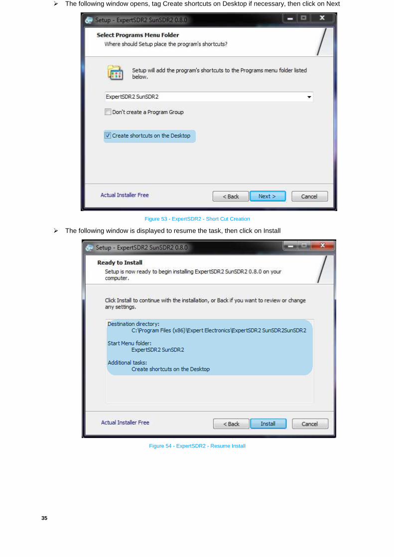
� The following window opens, tag Create shortcuts on Desktop if necessary, then click on Next
Figure 53 - ExpertSDR2 - Short Cut Creation
� The following window is displayed to resume the task, then click on Install
Figure 54 - ExpertSDR2 - Resume Install
36
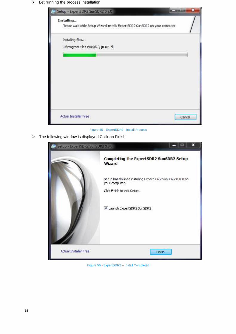
� Let running the process installation
Figure 55 - ExpertSDR2 - Install Process
� The following window is displayed Click on Finish
Figure 56 - ExpertSDR2 – Install Completed
37
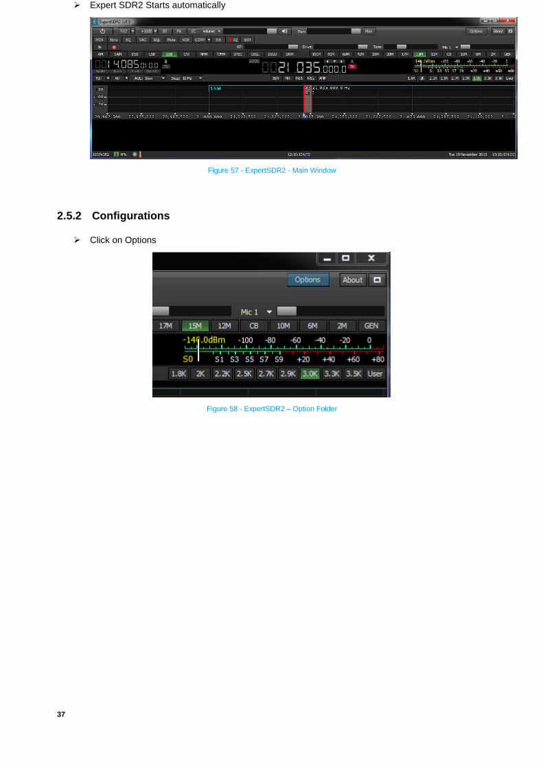
� Expert SDR2 Starts automatically
Figure 57 - ExpertSDR2 - Main Window
2.5.2 Configurations
� Click on Options
Figure 58 - ExpertSDR2 – Option Folder
38
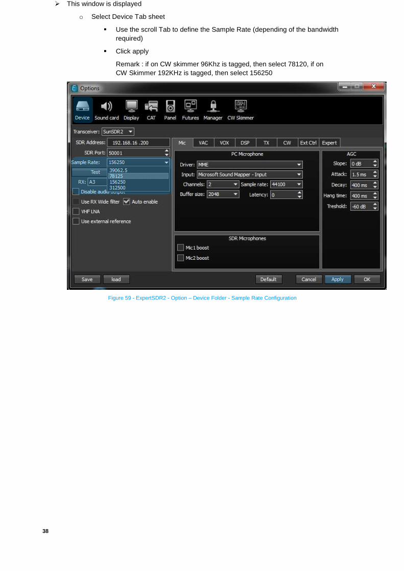
� This window is displayed
o Select Device Tab sheet
� Use the scroll Tab to define the Sample Rate (depending of the bandwidth required)
� Click apply
Remark : if on CW skimmer 96Khz is tagged, then select 78120, if on CW Skimmer 192KHz is tagged, then select 156250
Figure 59 - ExpertSDR2 - Option – Device Folder - Sample Rate Configuration
39
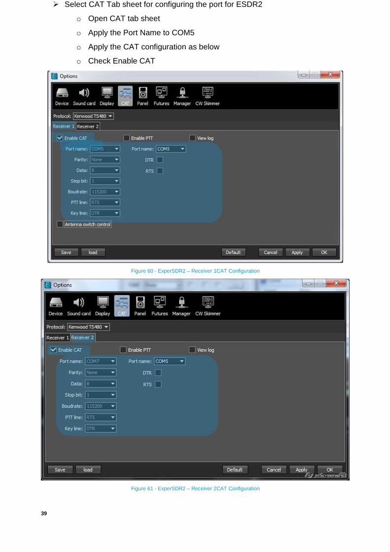
� Select CAT Tab sheet for configuring the port for ESDR2
o Open CAT tab sheet
o Apply the Port Name to COM5
o Apply the CAT configuration as below
o Check Enable CAT
Figure 60 - ExperSDR2 – Receiver 1CAT Configuration
Figure 61 - ExperSDR2 – Receiver 2CAT Configuration
40
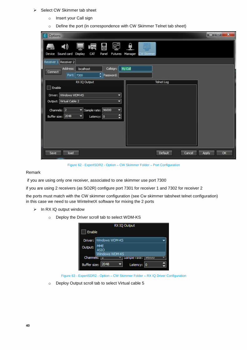
� Select CW Skimmer tab sheet
o Insert your Call sign
o Define the port (in correspondence with CW Skimmer Telnet tab sheet)
Figure 62 - ExpertSDR2 - Option – CW Skimmer Folder – Port Configuration
Remark
if you are using only one receiver, associated to one skimmer use port 7300
if you are using 2 receivers (as SO2R) configure port 7301 for receiver 1 and 7302 for receiver 2
the ports must match with the CW skimmer configuration (see Cw skimmer tabsheet telnet configuration) in this case we need to use WintelnetX software for mixing the 2 ports
� In RX IQ output window
o Deploy the Driver scroll tab to select WDM-KS
Figure 63 - ExpertSDR2 - Option – CW Skimmer Folder – RX IQ Driver Configuration
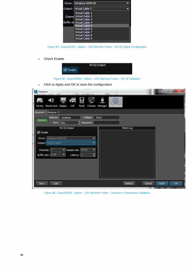
o Deploy Output scroll tab to select Virtual cable 5
41
Figure 64 - ExpertSDR2 - Option – CW Skimmer Folder – RX IQ Output Configuration
o Check Enable
Figure 65 - ExpertSDR2 - Option – CW Skimmer Folder – RX IQ Validation
o Click to Apply and OK to save the configuration
Figure 66 - ExpertSDR2 - Option – CW Skimmer Folder – Receiver 1 Parameters Validation

42
If the second receiver is used it’s necessary to declare the Virtual cable 6
Figure 67 - ExpertSDR2 - Option – CW Skimmer Folder – Receiver 2 Parameters Validation

43
� Select Futures tab sheet
o Define the path software’s who need to run with Expert SDR2
o Check them if necessary, these software’s will start automatically with Expert SDR2
Figure 68 - ExpertSDR2 - Option – Futures folder - Started Programs
� On the main window, select SKM to run in this mode manually
Figure 69 - ExpertSDR2 - Option – Main window - Skimmer Declaration
44
3 Contest Logger configuration
3.1 Introduction
This is a non-exhaustive list we can’t explain a configuration for each logger software. This list could be updated by the feed-back of all users.
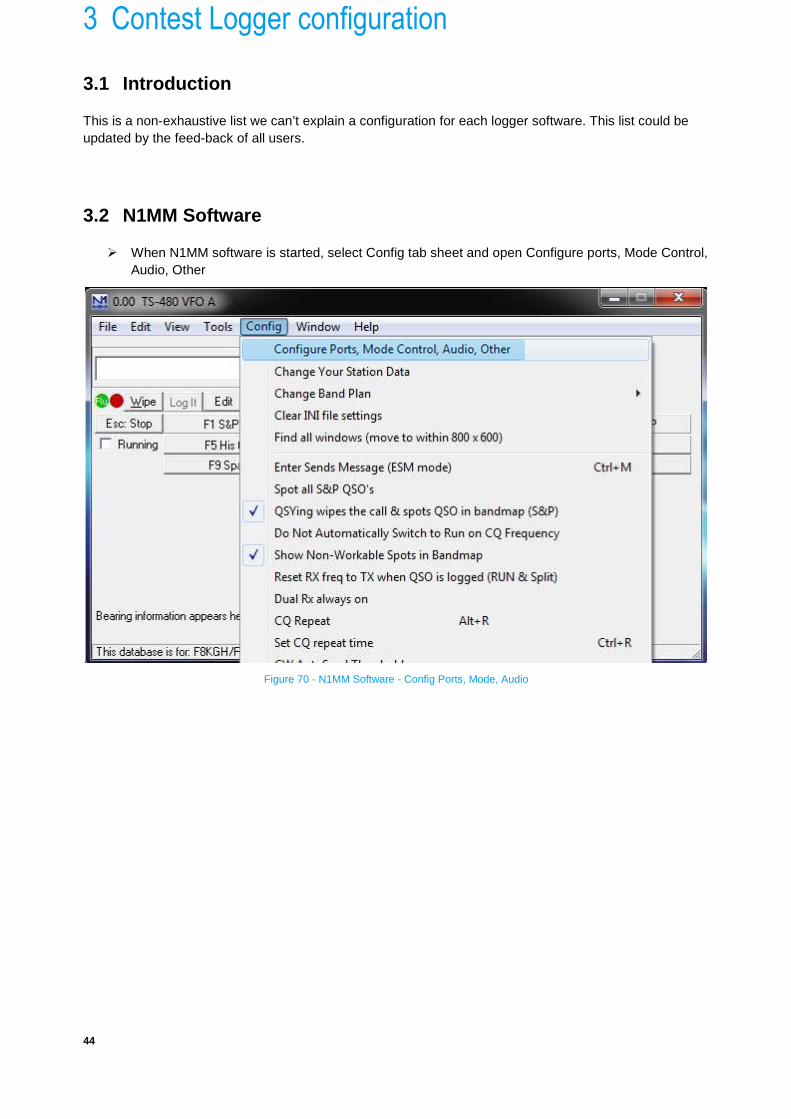
3.2 N1MM Software
� When N1MM software is started, select Config tab sheet and open Configure ports, Mode Control, Audio, Other
Figure 70 - N1MM Software - Config Ports, Mode, Audio
45
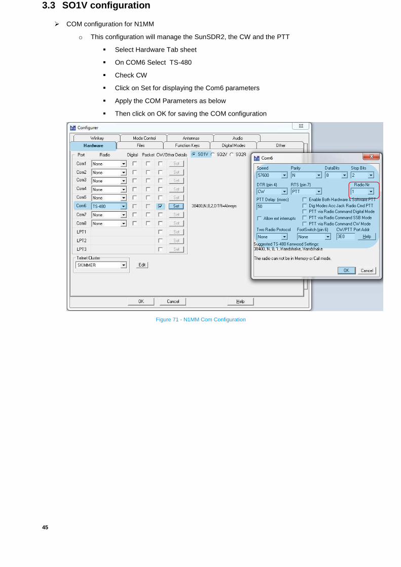
3.3 SO1V configuration
� COM configuration for N1MM
o This configuration will manage the SunSDR2, the CW and the PTT
� Select Hardware Tab sheet
� On COM6 Select TS-480
� Check CW
� Click on Set for displaying the Com6 parameters
� Apply the COM Parameters as below
� Then click on OK for saving the COM configuration
Figure 71 - N1MM Com Configuration

46
3.4 SO2R configuration
� COM configuration for N1MM
o This configuration will manage the SunSDR2, the CW and the PTT
� Select Hardware Tab sheet
� On COM8 Select TS-480
� Check CW
� Click on Set for displaying the Com8 parameters
� Apply the COM Parameters as below
� Then click on OK for saving the COM configuration

47
� This window will open
o In the Telnet Cluster click on Edit
.Figure 72 - N1MM Software - Config - Telnet Cluster Windows Location
48
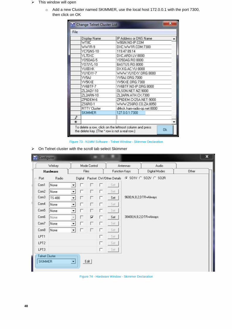
� This window will open
o Add a new Cluster named SKIMMER, use the local host 172.0.0.1 with the port 7300, then click on OK
Figure 73 - N1MM Software - Telnet Window - Skimmer Declaration
� On Telnet cluster with the scroll tab select Skimmer
Figure 74 - Hardware Window - Skimmer Declaration
49
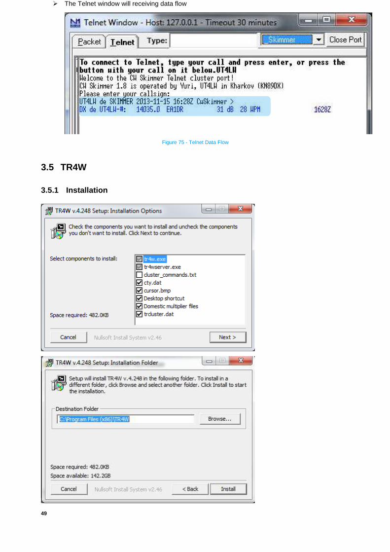
� The Telnet window will receiving data flow
Figure 75 - Telnet Data Flow
3.5 TR4W
3.5.1 Installation
50
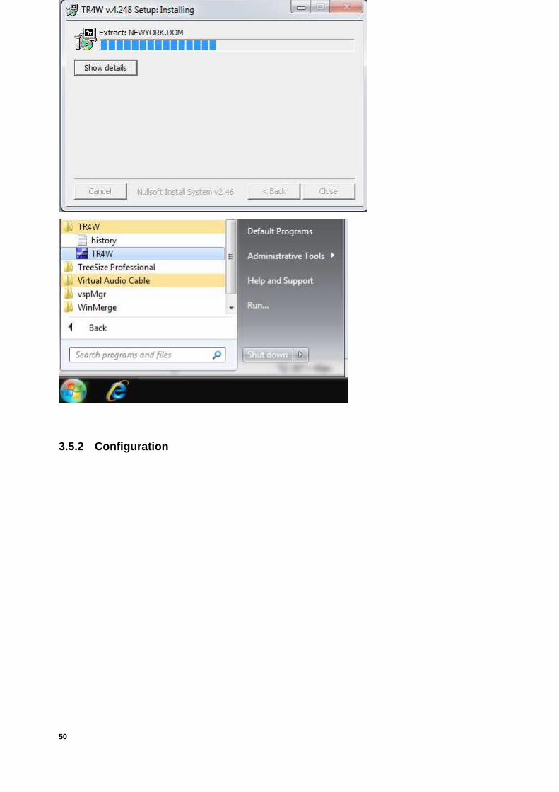
3.5.2 Configuration
51
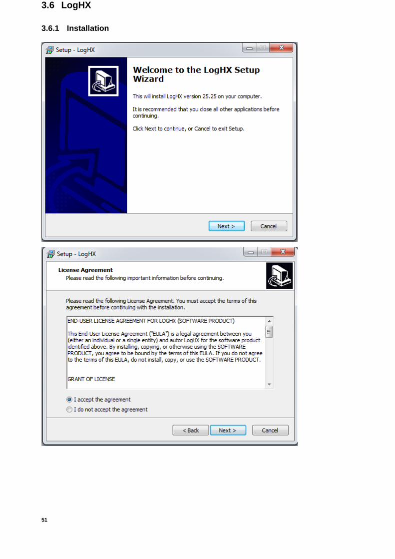
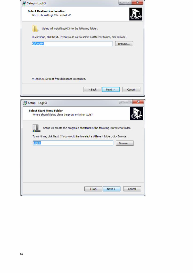
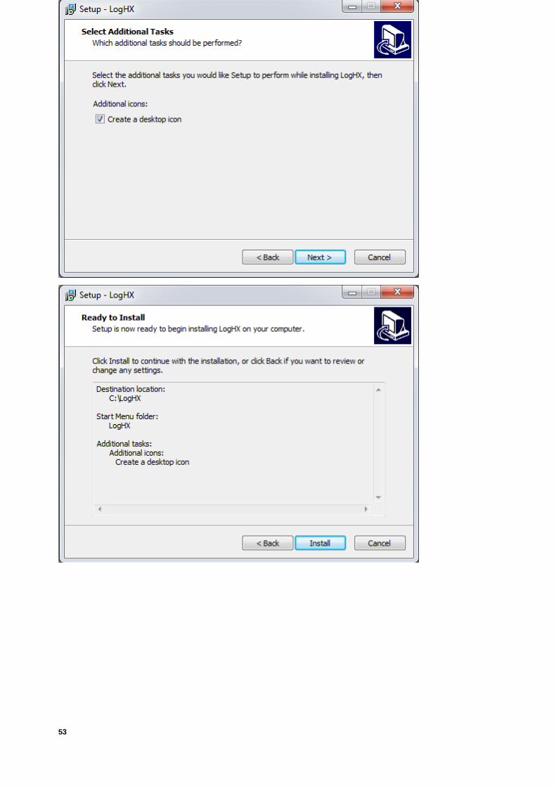
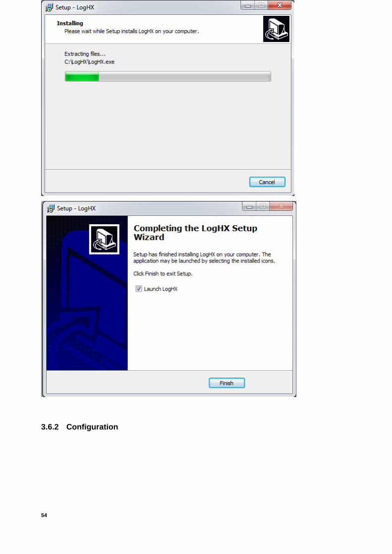
3.6 LogHX
3.6.1 Installation
52
53
54
3.6.2 Configuration